

Page 1
Instructions manual
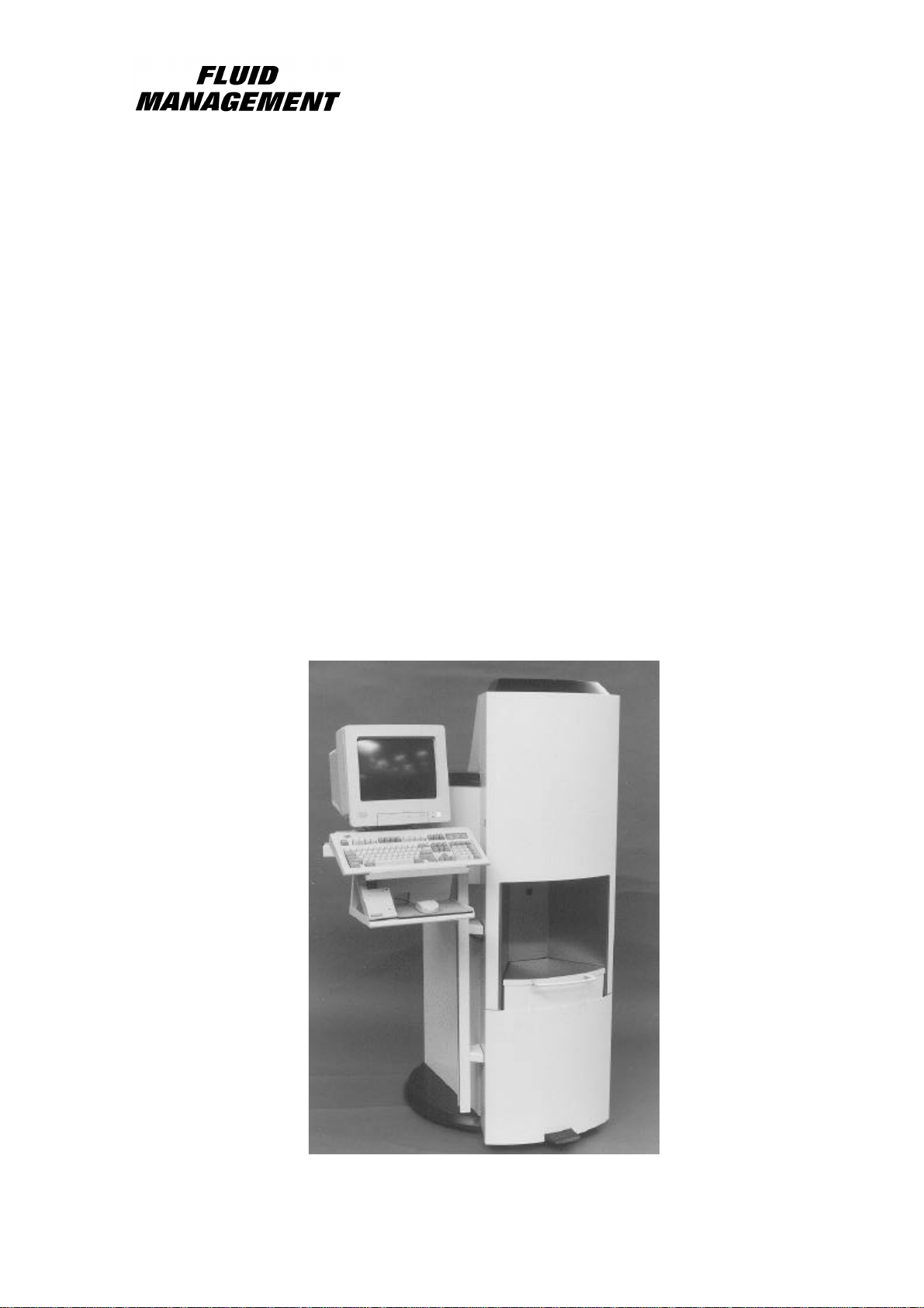
for the Dispenser
Type:
BT-Tintmaster
Illustrated model:
BT-16
1860330-eng
Page 2

Page 3

EU-declaration of conformity 1
We, Fluid Management Europe B.V.
A Unit of IDEX Corporation
Hub van Doorneweg 31
2171 KZ SASSENHEIM
herewith declare, on our own responsibility, that the products
HA-xs/s/m/l
BT-Tintmaster
which this declaration refers to, are in conformity with the following standard(s) or other such
specifications
NEN-EN 292-1, 1994
NEN-EN 292-2, 1996
NEN-EN 418
prNEN-EN 1050, 1993
NEN 2446, December 1976
NEN 3544, May 1984
EN 50081-1, 1992
EN 50082-1, 1992
EN 55024-2
EN 55024-4
NEN-EN 60204-1, 1995
EN 61000-3-2, 1995
according to the conditions of the Machinery-, Low Voltage- and the EMC-directive.
The Netherlands W. Van Westerop
Sassenheim, 5-5-1999 Vice President Manufacturing
Fluid Management Europe B.V.
A Unit of IDEX Corporation
Page 4

Table of contents
1. General page 3
2. Guarantee conditions page 4
3. Safety instructions and warnings page 5
4. Positioning/Installing the machine
4.1 Conditions for correct positioning page 6
4.2 Installing the machine
4.2.1 Preparation
4.2.2 Removing the floor model from the pallet page 7
4.3 Mounting the monitor stand and installing the computer system page 8
4.3.1 Mounting the monitor stand
4.3.2 Mounting the mouse and printer stand
4.3.3 Installing the computer system page 9
2
5. Operation page 10
5.1 Brief overview and function of the operating elements
5.2 Starting the machine page 11
5.2.1 Preparing the machine for use for the first time
5.2.2 Preparing the machine at the start of the day
6. Maintenance page 12
6.1 Maintenance instructions
6.2 Maintenance to be carried out by the operator
6.3 Troubleshooting page 13
6.4 Service/Service department page 14
7. Machine identification data page 15
7.1 Machine plate data
7.2 Pictures of the machine parts
7.2.1 Canister and dispensing pump page 16
7.2.2 Mains connection page 17
7.2.3 Power unit and sensor position page 18
8. Specifications page 19
Page 5

1 General
By selecting a Fluid Management Color Dispenser you have opted for a product which is the result of
intensive research in the field of high-tech color dispensing equipment. Top quality components,
craftsmanship and modern ergonomic design all serve to guarantee a long service life and a high
degree of user friendliness.
The equipment complies with Council Directives 89/392/EEC on machines, 89/336/EEC on
electromagnetic compatibility and 73/32/EEC on electrical material intended for use within given
voltage limits, as enacted by the Council of Ministers of the European Community. The equipment is
furnished with a CE mark.
Keep this manual in a safe place.
3
Page 6

2 Guarantee conditions 4
In these guarantee conditions, 'FM' is understood to mean Fluid Management Europe.
The guarantee conditions incorporated into FM's general conditions of sale are summarized as
follows (for free general conditions you can apply to FM):
1. FM guarantees the proper operation of any goods which it supplies, for a period of one year,
except where a breakdown is the result of normal wear and tear. The cost of any inspection
activities carried out by FM, with the aim of establishing whether or not a breakdown is covered
by the guarantee, will be reimbursed by the other party if it transpires that the breakdown is not
covered by the guarantee. If it transpires that a breakdown is covered by the guarantee, then FM
will supply identical or equivalent goods under the conditions referred to in point 6 of the general
conditions of sale. The guarantee obligation described in this article only applies if the goods
supplied by FM have been used in accordance with the manual. Time spent on guaranteerelated activities, including travel time, travel costs and accommodation costs, are charged at
current rates.
2. In contrast to the above, FM will not be held to any guarantee obligation if
a) repairs have been carried out, or attempted, by the other party or a third party, unless FM
had previously declined to repair the goods for a fair price;
b) FM demonstrates that the defect did not emerge during testing;
c) the other party fails to inform FM of the defect immediately, if possible either by letter
and/or by fax, providing full, accurate details and/or has failed to comply fully with FM's
instructions;
d) the other party has failed to use or treat the goods properly or in accordance with FM's
instructions;
e) the damage has been caused by incidents, beyond FM's supervision, which have occurred
either during transport or installation.
3. In the following text, the expression "Software" will be understood to mean the standard
computer software supplied by FM to the other party, recorded on a computer-readable storage
medium, plus the accompanying documentation (Software Manual) and including any improved
and/or new versions supplied. The expression "processing unit" (PU) is understood to mean the
machine for which and with which the Software is supplied, and which is the sole machine on
which the Software may be used.
4. The other party is authorized to copy the Software either in its entirety, or in part, (up to a
maximum of 2 copies) for purposes of internal security. These copies will be furnished with the
same marks, designations relating to copyright and other registration numbers as the original
version of the Software.
5. The other party will neither amend, translate, decompile nor adapt the Software, nor convert it
into source code, without express written permission from FM. If the other party so requests, FM
will provide that party with the information required to render the Software interoperable with
other software.
6. In the event that the PU experiences a breakdown, the other party may use the software on
another processing unit until the PU is again operational. The other party will inform FM of this
within 5 days.
7. If it is a requirement that the Software be definitively transferred from the PU to another
processing unit then the other party shall request permission from FM, which will not withhold
such permission on unreasonable grounds.
Page 7

3 Safety instructions and warnings 5
Before installing the equipment and setting it in operation, read the instructions for use
carefully. This is safer for you and it prevents needless damage to the machine.
The manufacturer accepts no liability if the instructions below are not followed:
• If a machine has been damaged (during transport, for example), do not attempt to set it in
operation. When in doubt, first contact either the Service department (see section 6.4) or your
supplier.
• The equipment should be positioned and connected up in strict accordance with the installation
instructions.
• All local safety regulations and ordinances should be observed.
• The machine may be connected only to a 230 V / 50 Hz / 60 Hz earthed wall socket installed in
accordance with the regulations.
• Users should see to it that the machine is kept in good condition. Defective components should
be replaced.
• In order to prevent physical injury, the doors should be closed and the panelling fitted during
normal use.
• Keep the keys of the machine in a special, safe place.
• All service activities (other than routine adjustments) may only be carried out by qualified
technicians. See to it that the mains lead is always kept unplugged while repairs are being
carried out.
• The standard equipment is only suitable for dispensing water-based color pastes into tins of basic
paint. The use of other solvents may damage the sealing rings and cause the equipment to leak.
The equipment can, however, be adapted for use with other solvents.
• Because of the design of the valve, a nozzle drill may never be used. Cleaning is done by
running the cleaning program.
Page 8

4 Positioning/Installing the machine 6
4.1 Conditions for correct positioning
Make sure that the following requirements are met when positioning the machine:
• Place the machine on a stable, flat surface, and make sure that it is level.
• Any dry, well ventilated place is suitable. The machine should preferably not be placed in the
sun or near a radiator or other source of heat, since this can cause the pastes to dry out.
• Maintain a constant ambient temperature of approximately 18oC to prevent viscosity changes in
the pastes.
• Make sure that the machine is connected only to a 230 V / 50 Hz / 60 Hz earthed wall socket.
4.2 Installing the machine
4.2.1 Preparation
Note: Tools and fastenings are supplied with the machine. They include spanners, cable connectors,
bolts, washers etc.
• Remove the plastic bag of lids and the installation kit from the lift table. Take the spanner out of the
installation kit and remove the side panel on the left side of the machine.
• Remove the fastening bolts attaching the machine to the pallet (see figure 1, number 1).
• Turn the adjustable feet at the front of the machine(see figure 1, number 2) all the way up.
• Remove the wooden slat from under the machine.
figure 1
3 2
1
Page 9

4 Positioning/Installing the machine 7
4.2.2 Removing the machine from the pallet
• Lift the machine slightly with the handles on the back of the machine and, with two people behind the
machine, pull the machine backwards (see figure 2).
• Carefully lower the back to the floor (figure 3).
• Carefully tip the machine slightly further so that the front is clear of the pallet.
• Slide the pallet away from under the machine and lower the machine carefully (figure 4).
• You can now wheel the machine to where you want it by lifting it by the handles on the back.
• Lastly, unscrew the adjustment feet at the front and back so that the machine is no longer resting on
the wheels, and is stable and level. (There are also adjustment feet at the back).
figure 2 figure 3 figure 4
Page 10

4 Positioning/Installing the machine 8
4.3 Mounting the monitor stand and installing the computer system
4.3.1 Mounting the monitor stand (optional on the BT) which can be mounted on the left or right of
the machine.
• Turn the four fastening bolts with washers and spring washers two turns in the fastening holes in the
base, as shown in figure 6.
• Drop the brackets of the monitor support over the bolts on the machine and tighten the bolts (spanner
10).
• Adjust the monitor brackets (see figure 7) to the correct size and tighten them.
• Remove the cover plates.
4.3.2 Mounting the mouse and printer stand (optional on the BT)
Attach the mouse and printer stand under the monitor stand with the bolts supplied (see figure 6/7).
monitor brackets
fastening bolts
figure 7figure 6
cover plate
(2x)
mouse /
printer stand
monitor /
keyboard arm
Page 11

4 Positioning/Installing the machine 9
Before proceeding any further :
Take the installation manual out of the computer packaging and look up the connection
information. This provides a clear description of all computer cables and plugs and the correct
way to connect them.
4.3.3 Installing the computer system (BT with optional monitor stand & mouse/printer stand where
applicable)
• Position the keyboard (2), the monitor (3) and the computer (4), (and the mouse (5) and label printer
(6) where applicable) as shown in figure 8.
• Feed the keyboard and monitor cables through the monitor stand into the machine (and the mouse
and label printer cables where applicable). See figure 9. Make sure they are running the right way!
• Connect the 9-pin serial connector from the powerunit to COM B of the computer.
• Attach the cover plates to the monitor stand.
• Bundle any loose pieces of cable with the cable ties supplied.
• Plug the computer and monitor plugs into the internal socket and switch them on with their on/off
switches
6 (option)
3
2
figure 8
5 (option)
figure 9
4
Page 12

5 Operation 10
3
10117
9
5.1 Brief overview and function of the operating elements
See figure 10 (elements shown with a dotted outline are located inside the machine).
1. Main switch (red)
2. Keyboard (various versions)
3. Monitor / Flat screen
4. Computer
5. Mouse 
6. Printer 
7. Cleaning brush/Brush tray
8. Lift table unlocking pedal
9. Can sensor
10. Flap (left and right)
11. Thermostat 
12. Computer switch (green)
¶ = Optional
⇒ Switching the machine on and off
⇒ Controlling the process
⇒ Monitoring and coordinating the process
⇒ Input and output control unit
⇒ Controlling the process
⇒ Printing label for dispensed paint colour
⇒ Cleaning the nozzles
⇒ Unlocking the lift table
⇒ Positioning cans at correct filling height
⇒ Closing the access opening to the canisters
⇒ Adjusting temperature of heating element
⇒ Switching the computer on and off
1
12
1
2
5
6
4
8
figuur 10
Page 13

5 Operation 11
5.2 Starting the machine
5.2.1 Preparing the machine for use for the first time
1. Turn the red main switch (see figure 10, number 1) to position <I> .
You are advised to leave this switch turned on at all times. This is necessary for the automatic
stirring system. It also reduces wear on the machine and the computer system.
Then turn also the green switch (see figure 10, number 12) to position <I>. Now the computer is
turned on. Switch the computer off at the end of the day.
2. Open the door of the machine and remove the brush tray. Fill the brush tray with water or a
diluted detergent (under no circumstances use a solvent!) up to the level mark. Replace the tray
in the correct position and close the door.
3. Use the software to set the stirring interval*.
4. Adjust the thermostat if installed (see the instructions for use supplied with the thermostat).
5. Fill the canisters with paste up to the indicated maximum level* by opening the flap and removing the
lid of the canister. The canister can now be filled to the top of the upper stirrer. Make sure that the
piston rod remains at the same height.
6. Ask your paste supplier for the stirring data for the pastes. It may be necessary to stir the pastes.
Stirring can be started with the aid of the software*.
7. Now you can start the morning program*.
5.2.2 Preparing the machine at the start of the day
1. Open the door of the machine and remove the brush tray. Fill the brush tray with water or a
diluted detergent (under no circumstances use a solvent!) up to the level mark. Replace the tray
in the correct position and close the door.
2. If necessary, top up the canisters to the maximum level. When you do this it may be necessary
to stir the pastes (ask your paste supplier).
3. Start the morning program*.
The machine is now ready for the day.
* see software manual
Page 14

6 Maintenance 12
6.1 Maintenance instructions
Always remove the power cord from the mains socket before commencing any maintenance
work on the machine.
1. Servicing and repairs may only be carried out by qualified personnel
2. Use good quality, appropriate tools only.
3. Use original Fluid Management parts only.
4. Before the machine is made available for use after service, all settings must be checked to
ensure that they are correct and the operating and safety systems must be checked to ensure
that they are functioning properly.
6.2 Maintenance to be carried out by the operator
Daily :
1. Clean the cleaning brush and replace the cleaning fluid in the brush tray (see 5.2.1, point 2).
2. Check nozzles for blockage by means of the morning program*. If there is a blockage, contact
the Service Department (see 6.4).
Weekly :
1. Remove spilt paste from the turntable and lift table.
2. Check the content of the canisters and top up to the indicated level. Update the content data
stored in the computer*.
Monthly :
1. Clean the computer cavity, the computer can be affected by dust.
2. Check the valves, valve housings and pumps for leaks..
3. Check that the valve handle is still in the correct position.
* see software manual
Page 15

6 Maintenance 13
ð
ð
ð
ð
ррррр
ð
6.3 Troubleshooting
Before calling in the Service Department, check whether you can solve the problem yourself. If you
cannot, call the Service Department for advice (see 6.4). Have the model number and serial number
to hand. They can be found on the nameplate on the machine (see 7.1).
Use the chart of Problem, Cause and Action below to judge whether you can solve a problem yourself
or whether you will need to call in the Service Department. The symbol means that the Service
Department must be called.
This chart does not include any of the malfunctions which are reported in an error message by the
software. In the event of a malfunction, these messages and possible solutions are displayed on the
monitor.
Problem Cause Action
Valve leaks through the outlet
opening
Canister connection leaks around
the suction point
Air is being fed together with the
paste
(New) software is not working
Sensors are not working
No power from power unit
Valve is defective
Worn O-ring(s)
6. Air in the pump
7. Canister is empty
8. Piston is defective
9. Valve handle spring broken
1. Diskette is damaged
2. Wrong data
3. Program not loaded correctly
5. Main switch is off
6. Cables to power unit are loose
7. No mains power
8. Fuse has blown
1. Main switch is off
2. Cables to power unit are loose
3. Fuse has blown
Replace valve
ð
Replace O-ring(s)
ð
1. Bleed the pump
2. Add paste
ð
3.
4.
1. Request new diskette
2.
ð
3. Reload programm
1. Turn main switch to position <I>
2. Remove plugs from socket, check
ð
ð
cables
3. Check if there is mains power
4. Remove plug from socket,
replace fuse
1. Turn main switch to position <I>
2. Remove plugs from socket, check
cables
3. Remove plug from socket,
replace fuse
There is no 230 V 5. Main switch is off
6. No power to (internal) socket
7. Fuse has blown
Colours are difficult to reproduce
Poor monitor picture, or no picture
1. Mechanisms are dirty
2. Quality fluctuations in paste supplied
3. One or more pastes have thickened
4. Leaks around piston(s)
5. Turntable in wrong position
6. Valve handle spring is broken
6. Monitor is switched off
7. Loose cable(s)
8. Picture set too dark
9. Monitor malfunctioning
1. Turn main switch to position <I>
2. Check electrical wiring
3. Remove plug from socket,
replace fuse
1. Clean and oil
2. Contact paste supplier
3. Replace paste(s)
4. Replace piston(s)
ð
5. Press reset and test (see fig. 11)
6.
1. Switch monitor on
2. Check cables
ð
3. Adjust picture correctly
4.
Page 16

6 Maintenance 14
ð
ð
ð
Keyboard is not working
Stirrer is not rotating
Turntable is not turning
Lamp
1. Loose cable(s)
2. Defective cable(s)
3. Keyboard is defective
4. Keyboard setting is incorrect
5. Loose cable
6. Timer setting incorrect
7. Defective cable
8. Defective motor
1. Piston rod positioned too high
2. Valve mechanism open
3. Cable(s) loose
4. Cable or motor defective
1. Check cables
2.
ð
3.
4.
1. Check cable
2. Use the software to set timer
ð
ð
correctly
3.
4.
6. Set piston in lowest position
7. Press ‘reset’ and ‘test’ (see fig.
11)
8. Check cables
9.
Reset
Test (press in and hold for 3 sec.)
figure 11
Press the reset button if your machine is not working properly and a red light comes on just above the
reset button. A green lamp will then light up.
Now press the test button and hold it in for at least 3 seconds. The machine will test all components
and can then be used again.
Contact the manufacturer if this procedure does not give the desired result.
6.4 Service/Service department
If necessary, you can get in touch with your supplier or the local service department, or contact the
manufacturer directly. If you contact the manufacturer, make sure that you have the model number
and serial number to hand. They can be found on the nameplate on the machine (see 7.1).
Fluid Management Europe
P.O. Box 220
2170 AE Sassenheim, Netherlands
Hub van Doorneweg 31
2171 KZ Sassenheim, Netherlands
Tel. : 0031 252 240800
Fax : 0031 252 240882 (service)
0031 252 240880 (general)
Page 17

7 Machine identification data 15
7.1 Machine plate data
To reach the machine plate, first open the front door of the machine. The plate is situated on the left
side of the machine in the upper left corner.
P.O.Box 220
2170 AE Sassenheim, Holland
Weight
V~ Hz
kg
W
A
Model
Serial
nr.:
nr.:
Page 18

7 Machine identification data 16
stirrer
7.2 Pictures of the machine parts
7.2.1 Canister and dispensing pump
lid
canister
valve handle
spring
piston rod
piston
figure 12
nozzle
nozzlecloser
valve lever
Page 19

7 Machine identification data 17
7.2.2 Mains connection
figure 13
Mains
connection
6A fuse
Page 20

7 Machine identification data 18
7.2.3 Power unit and sensor position
2A fuses (2x)
Powerunit
Sensor 2
Sensor 5
Sensor 6
Sensor 4
figure 14
Page 21

8 Specifications 19
BT
Polymeric canisters, contents: 1,75 liter
Teflon pistons
Stainless steel pumps
Number of canisters 12, 14 of 16
Height 1675 mm
Width
Weight ± 130 kg
Mains voltage 230 V ~ 50 Hz
Amperage
Computer system
A-weighted equivalent continuous sound pressure
• IBM-keyboard
• without keyboard
ü
ü
1175
790mm
1,5 Ampère
ü
< 70 dB(A)
 Loading...