

Page 1

FAST & FLUID MANAGEMENT
AT550
ENGLISH
User manual
Page 2

© Fast & Fluid Management, AT550
p2
Page 3

© Fast & Fluid Management, AT550
AT550 Manual
4
EU Declaration of conformity
4
Introduction & Warranty
5
Explanation of picture
6
Safety Instructions
7
Installation
8
Operation
10
Maintenance
14
Troubleshooting
16
Technical specifications
17
Contributing to the Protection of the Environment
18
Table of Contents
p3
Page 4

© Fast & Fluid Management, AT550
Produkt:
Automatic dispensers
Model:
Accutinter
Types:
AT550
AT550 Manual
EU Declaration of conformity
Fast & Fluid Management, the Netherlands
A Unit of IDEX Corporation
Hub van Doorneweg 31
2171 KZ Sassenheim, the Netherlands
declare that:
are in compliance with the following directives:
Machinery Directive 98/37/EC
Low Voltage Directive 73/23/EEC
Electromagnetic Compatibility Directive 89/336/EEC
according to the following harmonized standards:
EN 292-1, EN 292-2, EN 418 & EN 1050
EN 60204-1
EN 61000-6-2, EN 61000-6-3, EN 61000-3-2 & EN 61000-3- 3
Sassenheim, 01-06- 2005
ir. F. Puijman
Vice President Manufacturing
Fast & Fluid Management, the Netherlands
A Unit of IDEX Corporation
p4
Page 5

© Fast & Fluid Management, AT550
Introduction & Warranty
Introduction
By selecting a Fast & Fluid Management Color Dispenser you have opted for a product which is the result of
intensive research. Top-quality components, craftsmanship and a modern ergonomic design all serve to
guarantee a long service life and a high degree of user friendliness. The m achine c omplies with Council
Directives 89/392/EEC on machines, 89/336/EEC on electromagnetic c ompatibility, and 73/32/EEC on electrical
equipment intended for use within given voltage limits, as enacted by the Counc il of Ministers of the European
Community. The machine is furnished with a CE m ark.
Warranty conditions
In these warranty conditions, 'F&FM' is understood to mean Fast & Fluid Managem ent. The warranty conditions
incorporated into F&FM's general c onditions of sale are summarized as follows (for free general conditions you
can contact F&FM):
F&FM guarantees the proper operation of any goods which it supplies, for a period of one year, exc ept where a
breakdown is the result of normal wear and tear. The cost of any inspection activities carried out by F&FM, with
the aim of establishing whether or not a breakdown is covered by the warranty will be reim bursed by the other
party if it transpires that the breakdown is not covered by the warranty. If it transpires that a breakdown is
covered by the warranty then F&FM will supply identical or equivalent goods under the c onditions referred to in
point 6 of the general conditions of sale. The warranty obligation described in this article only applies if the
goods supplied by F&FM have been used in accordance with the manual. Time spent on warranty-related
activities, including travel time, travel costs and accommodation costs, are charged at current rates.
In contrast to the above, F&FM will not be held to any warranty obligation if:
Repairs have been carried out, or attempted, by the other party or a third party, unless F&FM had
1.
previously declined to repair the goods for a fair price;
F&FM demonstrates that the defect did not emerge during testing;
2.
The other party fails to inform F&FM of the defect immediately, if possible either by letter and/or by fax,
3.
providing full, accurate details and/or has failed to comply fully with F&FM's instructions;
The other party has failed to use or treat the goods properly or in accordance with F&FM's instructions;
4.
The damage has been caused by incidents, beyond F&FM's supervision, which have occurred either during
5.
transport or installation.
In the following text, the expression "Software" will be understood to mean the standard computer software
supplied by F&FM to the other party, recorded on a computer-readable storage medium, plus the accompanying
documentation (Software Manual) and including any improved and/or new versions supplied. The expression
"processing unit" (PU) is understood to mean the mac hine for which and with whic h the Software is supplied,
and which is the sole machine on which the Software may be used.
The other party is authorized to copy the Software either in its entirety, or in part, (up to a m aximum of 2
copies) for purposes of internal security. These copies will be furnished with the same marks, designations
relating to copyright and other registration numbers as the original version of the Software.
The other party will neither amend, translate, decompile nor adapt the Software, nor convert it into source
code, without express written permission from F&FM. If the other party so requests, F&FM will provide that
party with the information required to render the Software interoperable with other software.
In the event that the PU experiences a breakdown, the other party may use the software on another processing
unit until the PU is again operational. The other party will inform F&FM of this within 5 days.
If it is a requirement that the Software be definitively transferred from the PU to another processing unit then
the other party shall request permission from F&FM, which will not withhold such permission on unreasonable
grounds.
p5
Page 6
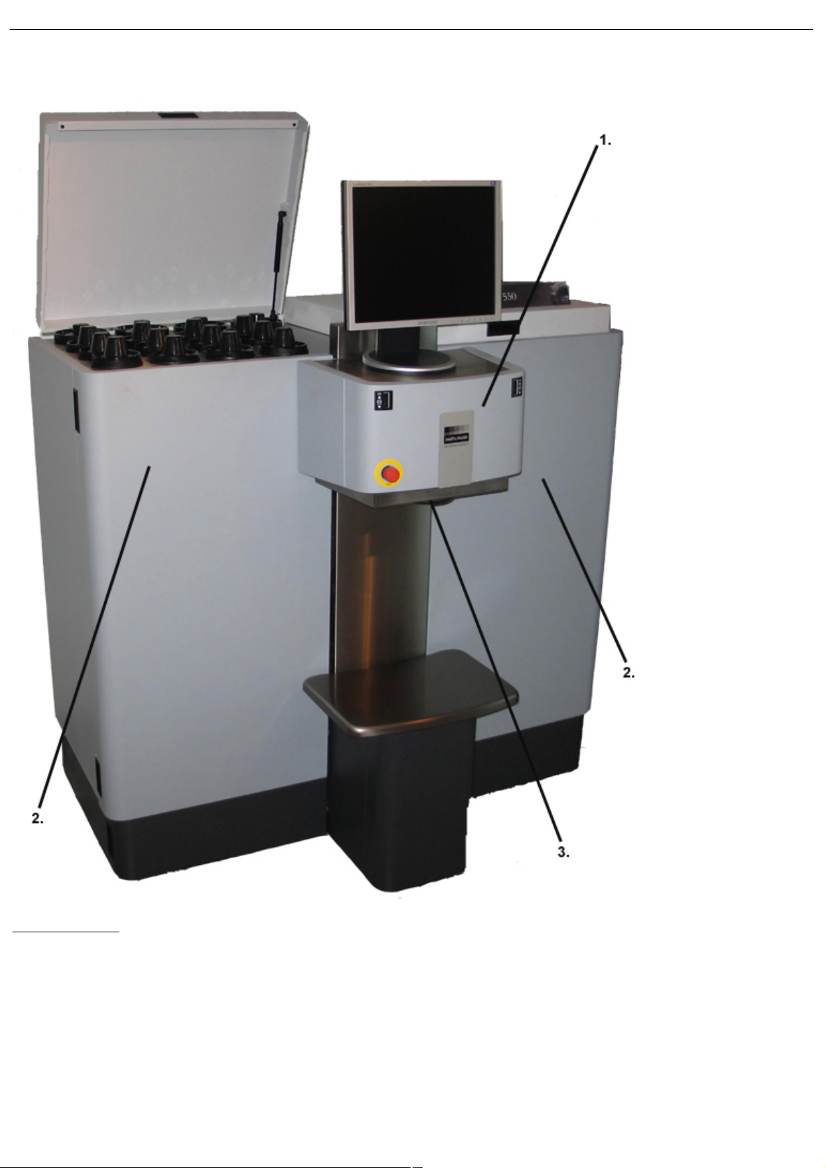
Explanation of picture
Dispenser
1.
Dispenser module
2.
Canister module
Service panels
3.
Electrical parts
Nozzle closure
Nozzle guard
© Fast & Fluid Management, AT550
p6
Page 7

© Fast & Fluid Management, AT550
Attention! Before installing the equipment and setting it in operation,
please read the instructions for use carefully. This is safer for yourself and
prevents unnecessary damage to the machine.
Attention! MOVING PARTS CAN CAUSE INJURY. Always turn off power
before accessing moving parts.
Safety Instructions
General safety instructions
The manufacturer accepts no liability if the instructions below are not followed:
If a machine has been damaged (during transport, for example), do not attempt to set it in operation. When
1.
in doubt, first contact either your supplier or the F&FM service department.
The equipment should be positioned and connected up in strict accordance with the installation instruc tions.
2.
All local safety regulations and ordinances should be observed.
3.
The machine may be connected only to a 230V/16A/50Hz or 100-110V/25A/50-60HZ earthed wall socket
4.
installed in accordance with the regulations.
Users should see to it that the machine is kept in good condition. Defective components should be replaced.
5.
In order to prevent physical injury, the doors should be closed and the paneling fitted during normal use.
6.
All service activities (other than routine maintenance and adjustments) may only be carried out by qualified
7.
technicians. See to it that the mains lead is always kept unplugged while repairs are being carried out.
Because of the design of the valve, a nozzle drill may never be used. Cleaning is done by running the
8.
cleaning program.
Specific warnings in this manual
p7
Page 8

Installation
Step 1 - Unpack the machine
>
>
Place the crate near the place
of installation.
Remove the cardboard box
and remove the plastic foil
around the machine.
Remove the two bottom
panels to access the screws
that are connected to the
crate.
Be careful not to damage the body and surfaces of your AT550 with any
tools while unpacking it.
>
>
Remove the bolt's on both
sides.
Carefully lift the machine
from the skid with a fork lifter
and roll the machine to its
final operational position.
Lower the 3 adjustable feet
far enough to lift the m ac hine
off its wheels. Lock it with the
locknut.
A - Installing the dispenser
© Fast & Fluid Management, AT550
p8
Page 9

© Fast & Fluid Management, AT550
Step 1 - Place and connect computer to dispenser
>
>
Remove the bottom panel.
Computer can be plac ed in
lower compartment.
Monitor and keyboard can be
placed on top of the
dispenser
Step 2 - Install dispenser software on computer
>
>
Connect dispenser USB cable
and mouse, keyboard and
other appliances to
design-nated computer ports.
Install all necessary software
provided by software
supplier. Check software
manual for details.
Use software to test basic
functions of dispenser before
filling.
Check software manual for
testing procedure.
B - Installing the computer and software
p9
Page 10

Operation
Step 1 - Switching ON the dispenser & computer
>
>
The machine is
automatically switched on
when the power connector
at the back of the
dispenser is plugged into a
220V or 100V-110V wall
socket.
* We recommend to keep
the machine on at all
times.
The dispense abort switch
must be released.
The green button only
swithces internal wall soc ket.
Step 2 - Setting the stirring time
>
The stirring time and interval can be altered from its default
settings*. This can be done through the dispenser software, check
your software manual for instructions.
Please ask your paint supplier for optimal agitation settings for
your specific colorant products.
* Default value is 180 seconds of agitation every 3 hours.
A - First time operation
© Fast & Fluid Management, AT550
p10
Page 11

© Fast & Fluid Management, AT550
Step 3 - Fill the nozzle closure.
>
>
Lift the switch plate and
move it towards the mac hine.
Lower the switch plate under
the dispense head.
Use the appropriate
comm and from the dispenser
software to open the nozzle
closure. Remove the c up
holder.
Moisturise the cup with water
or cleaning fluid until the pad
is soaked.
Replace the cup holder in its
original position. Replace the
switch plate.
Use only cleaning fluids recommended by your paint supplier.
Wrong materials can result in nozzle blockage and reduced accuracy.
p11
Page 12

© Fast & Fluid Management, AT550
Step 4 - Fill the canisters with colourant
>
Check your software manual
for filling sequence.
Run software purge program
until the air is removed from
system.
p12
Page 13

B - Dispensing
Step 1 - Bring can to correct position
>
>
Place the can at the right
place of the can table.
Hold the can table and unlock
the index pin with the foot
pedal.
Lift the can table until the
can is in reach of the can
sensor. The can should be
just below the switch plate.
Release the index pin. Gently
release the can table.
Step 2 - Dispense colorant into base material
>
>
Ensure can opening is
under the dispenser
nozzlehead and at its
optimal height
Choose desired formula as
shown in software m anual.
The dispenser will
sub-sequently dispense the
colorants.
Lower can table if applicable.
© Fast & Fluid Management, AT550
p13
Page 14

Maintenance
Clean the nozzle closure, refill canisters and run morning program
>
>
Replace the pad. Refill the
cup with water or cleaning
fluid until the pad is soaked.
Fill canisters if level is low
and update levels in software.
Stir colorant beforehand.
Start software m orning
program to purge valves and
clean nozzles. Chec k your
software manual for details.
Use only cleaning fluids recommended by your paint supplier. Wrong
materials can result in nozzle blockage and reduced accuracy.
Remove spilt paint & colorant and refill canisters
>
>
Clean can table and outside
parts with diluted detergent.
Clean outside parts with
diluted detergent.
Check canister content and
refill if necessary.
A - Daily maintenance
© Fast & Fluid Management, AT550
B - Weekly maintenance
p14
Page 15

C - Monthly maintenance
>
Remove back panel.
Check pump for possible
malfunctions
(e.g. leakage or blockage).
Attention! MOVING PARTS CAN CAUSE INJURY. Always turn off power
before accessing moving parts.
© Fast & Fluid Management, AT550
p15
Page 16

© Fast & Fluid Management, AT550
Attention! MOVING PARTS CAN CAUSE INJURY. Always turn off power
before accessing moving parts.
>
Spare fuse Defect
Troubleshooting
A - Introduction
Before calling your machine supplier or Service Department, please chec k whether you can solve the problem
yourself. If you cannot, then call the Service Department for advice. Have the model number and serial number
at hand (these can be found on the silver CE sticker at the service panel at the back of the m achine).
Use the Problem Solving chart below to judge whether you can solve a problem yourself or not. The tool symbol
( ) means you cannot solve the problem yourself and the Service Department must be called. On no occasion
remove side panels yourself, this may only be done by trained service personnel. This chart does not inc lude
any of the malfunctions which are reported in an error message by the software. In the event of a m alfunction,
these messages and possible solutions are displayed on the monitor.
B - Service Department
If necessary, you can get in touch with your supplier or the local service department, or contact the
manufacturer directly. If you contact the manufacturer, m ake sure that you have the model number and serial
number to hand. They can be found on the name plate on the back of the mac hine.
Fast & Fluid Management
P.O. Box 220
2170 AE Sassenheim, the Netherlands
Hub van Doorneweg 31
2171 KZ Sassenheim, the Netherlands
Tel: + 31 (0)252 240 800
Fax: +31 (0)252 240 882 (service)
+ 31 (0)252 240 880 (general)
C - Replace fuses
p16
Page 17

Technical specifications
© Fast & Fluid Management, AT550
p17
Page 18

© Fast & Fluid Management, AT550
All red-coloured components
are made of ABS. These
components can be recycled.
Inside the red square
pictured above (on the front
of the dispenser) are
electrical components that
can be recycled.
Contributing to the Protection of the Environment
Packaging Material
The packaging protects the machine against damage during transport. The packaging material was chosen
based on its limited impact on the environm ent and its inherent possibilities for waste- disposal.
The reuse of packaging material saves raw materials and produces less waste m aterial. Generally speaking,
your supplier will take the packaging off your hands.
Discarding the Machine
Discarded equipment usually still c onsists of valuable materials. For this reason, do not simply throw your
machine out with the oversized refuse, but ask your supplier whether he will take the m achine back.
If he will not, then enquire at your local government offices or ask a trader of raw materials what options there
are for recycling the material (e.g. scrap processing, electrical components and plastic (see below for additional
information).
p18
Page 19

© Fast & Fluid Management, 2007
ww w .Fast-Fluid.com
 Loading...