

Page 1
HARBIL 5G High Speed Paint Mixer
with Enhanced Clamping Circuitry
End User Guide
Part No: 24018
Rev. G 06.14
Page 2

Page 3

Your
customers have a vision,
you want to make it happen, and
Fluid Management can give you the answer.
Fluid Management is a global leader in dispensing
and mixing equipment used in the paint industry, as
well as, specialized equipment for the food and beverage,
chemical, health and beauty, and home improvement industries.
Located in the suburbs of Chicago, Illinois, Fluid Management is
a United States owned and operated company with historical roots
to the paint industry dating back to 1927. In 1996, IDEX Corporation
purchased Fluid Management giving the organization the financial
wherewithal and global footprint of a large organization while still maintaining
its deep values and history.
As industry leaders, Fluid Management provides trend-setting creativity in the
design, products, and services it offers. United with FMDirect, our nationwide
service team, we provide after-sales support around the clock—when you need
them. Being factory-direct employees, FMDirect technicians are experts on Fluid
Management equipment and understand customer needs from start to finish.
The combination of leading edge technology, excellent service and support, and
a company prepared for the future’s ever-changing business environment makes
Fluid Management an ideal partner to assist in providing solutions to your business
needs. Thank you for putting your trust in Fluid Management products and making
us part of your customer’s vision.
Page 4

©2014 Fluid Management as published work all rights reserved.
Under the copyright laws, this material may not be copied, in whole or in part, without
the written consent of Fluid Management.
Your rights to the software are governed by the accompanying software license
agreement.
Use of Fluid Management trademarks, service marks, or logos for commercial purposes without
the prior written consent of Fluid Management may constitute trademark infringement and unfair
competition in violation of federal and state laws. Fluid Management, FMDirect, ColorPro,
DVX, Harbil, Blendorama, Accutinter, Duraow, Fast & Fluid Management, GyroDispenser, Inna,
MicroTint, TintMaster, V1, and VR1 are trademarks of Fluid Management, registered in the U.S.
and/or other countries.
Every effort has been made to ensure that the information in this guide is accurate.
Fluid Management is not responsible for printing or clerical errors.
Fluid Management
1023 Wheeling Road
Wheeling, Illinois 60090-5776 USA
800-462-2466
http://www.fluidman.com
Published in the United States.
Mention of third-party products is for informational purposes only and constitutes
neither an endorsement nor a recommendation. Fluid Management assumes no
responsibility with regard to the performance or use of these products.
2 | Harbil 5G Mixer
Fluid Management Customer Ser vi ce 1 . 800 . 462 . 2 466
Page 5

Contents
Safety Information
4 Mixer Warning Labels
4 Safety Notice Information
Introduction
6 Product Descriptions
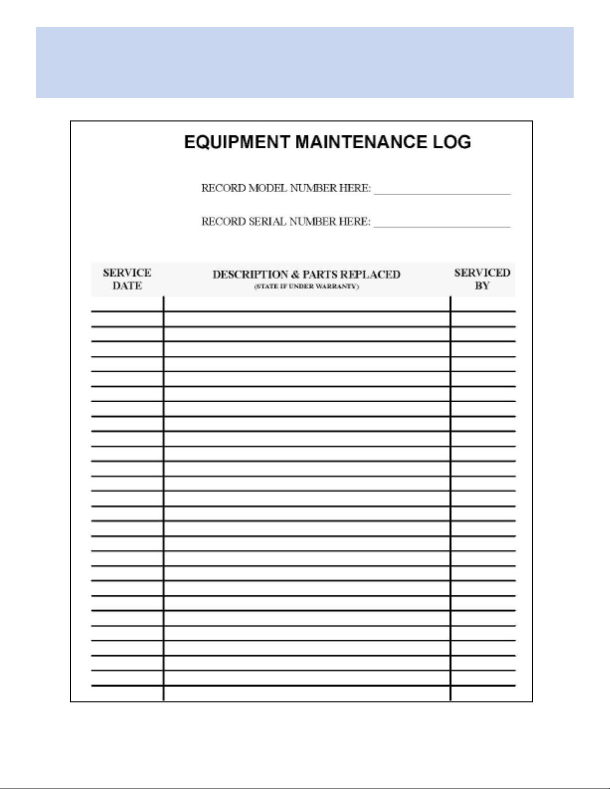
7 Equipment Maintenance Log
8 Spare Parts Order
Unpacking Directions
9 Inspect the Crate for Damage
9 Unpacking and Setup
Electrical Conditions
10 Grounding
10 Danger
Aligning and Leveling Mixer
11 Aligning the Struts
11 Level i ng
12 Remove Shipping Inserts
Getting to Know Your Paint Mixer
13 General Locations
14 Control Panel
14 Revisable Door
Important Information
15 Warnings
15 Cautions
Basic Operation
16 Basic Operation Procedure
Operational Test
19 Operational Test Procedure
Maintenance Procedures
20 General Lubrication
21 Super-Struts Lubrication
Troubleshooting
22 Troubleshooting Tables
Servicing and Repair
26 General Information
26 Safety Procedure
Opening Mixer
27 Remove the Exterior Panels
Removing Shake Frame
28 Removing Shake Frame Procedure
30 Remove the Counterweights
Testing Shake Motor
32 Testing Shake Motor Procedure
Changing Shake Motor
33 Changing Shake Motor Procedure
Changing the V-Belt
34 Changing the V-Belt Procedure
Removing Circuit Board
35 Removing Circuit Board Procedure
Installing Rubber Pads
36 Installing Rubber Pads Procedure
Replacing/Adjusting DC Motor
38 DC Clamping Motor Replacement/Adjustment
Adjusting Clamping Force
39 Clamping Force Adjustment Procedure
Reversing Door
42 Reversing Door Procedure
Replacing Super-Struts
44 Removing the External Panels
44 Removing the Super-Struts
47 Installing the Super-Struts
Replacing Crankshaft
50 Access the Crankshaft
50 Remove the Crankshaft
51 Install New Crankshaft
Reassembling Mixer
53 Reassembling Mixer Procedure
54 Test Procedure
Parts Section
56 Sheet and Metal Outer Frame
60 Control Box Assembly
62 Inner Frame
64 Shake Frame
70 Clamping Motor Assembly
72 Top Plate Assembly
74 Crankshaft Assembly
Fluid Management Customer Ser vi ce 1 . 800 . 462 . 2 466
Fluid Management Customer Ser vi ce 1 . 800 . 462 . 2 466
Warranty
76 Paint Equipment Limited Warranty
Harbil 5G Mixer | 3
Page 6

Safety Information
Safety
Information
Mixer Warning Labels
You should become familiar with important warning labels which are afxed to the
mixer, as well as the symbols which appear throughout this manual. These warnings
have been included to help you safely perform your job.
Please read all warning labels that are on the mixer. Keep them clean so they are
easy to read. If the warning labels become damaged or unreadable, new labels can
be purchased from Fluid Management. See the parts list in the back of the manual
for ordering information.
Safety Notice Information
The two main safety notices used in this manual are Warning and Caution. Notices in
this manual will look like the example below.
Warning Notice
ELECTRICAL HAZARD
Do not operate the mixer with the door
open. Disconnect power before servicing.
WARNING
A Warning notice tells you about a hazard that could cause serious injury to you or
extensive damage to the mixer. This information is placed at the beginning of the
manual to emphasize the importance of safety to your well being.
When you see a Warning notice in this manual, read it carefully. Before continuing
with the operation of the mixer, take all necessary precautions to avoid potential
injury.
Caution Notice
ELECTRICAL HAZARD
All electrical components must be kept
CAUTION
A Caution notice tells you about a danger that could cause injury to you or minor
damage to the mixer. When you see a Caution notice in this manual, read it carefully
and be sure you understand it before continuing.
dry. Never place containers of liquid on
or near the control box.
4 | Harbil 5G Mixer
Fluid Management Customer Ser vi ce 1 . 800 . 462 . 2 466
Page 7

Safety Information
Information Notice
Note: If the cabinet vibrates, loosen the locking nuts on the right
front leveling foot and slightly adjust the length.
An Information notice gives details that will assist you in efciently using the mixer.
When you see an Information notice in this manual, know that it is there to save you
time and energy.
Compliance Information
See the afxed labeling on the machine for safety and regulatory compliance
information. ETL Listed, conforms to UL STD 1450. Certied to CAN/CSA STD
C22.2 No.68 (120 V model only).
Fluid Management Customer Ser vi ce 1 . 800 . 462 . 2 466
Harbil 5G Mixer | 5
Page 8

Introduction
Introduction
The Harbil 5G High Speed Paint Mixer is a versatile, automatic mixer designed with
concern for safety, reliability and ease of use. Its features include:
• Heavy-duty, high-capacity components and a durable finish for long wear.
• Vibration-free mixing for blending and conditioning paint.
• Versatile mixing times from 30 seconds to 3 minutes
• Handles pint, quart, gallon, and 5-gallon containers.
Important safety features are:
• Automatic shut off if the door is opened during the shaking operation.
• Fully visible red STOP switch for emergency shut off.
Product Description
Specications
Height 45.5” (115.6 cm)
Width 28” (71.0 cm)
Depth 28” (71.0 cm)
Weight 470 lb (213.2 kg)
Contain Capacity
Maximum height 17.5” (44.5 cm.)
Minimum height 0.5” (1.3 cm)
Diameter 13.5” (34.3 cm)
6 | Harbil 5G Mixer
Typical Electrical Supply
See name plate for specic information.
120 V ± 10%, 60 Hz, 11.8 A
220 V ± 10%, 50 Hz, 6.0 A
Fluid Management Customer Ser vi ce 1 . 800 . 462 . 2 466
Page 9
Introduction
Fluid Management Customer Ser vi ce 1 . 800 . 462 . 2 466
Harbil 5G Mixer | 7
Page 10

8 | Harbil 5G Mixer
Fluid Management Customer Ser vi ce 1 . 800 . 462 . 2 466
Page 11

Unpacking Directions
Inspect the Crate for Damage
IMPORTANT
Unpacking and Setup
Refer to the Unpacking and Setup Instructions afxed to the shipping carton in a
mailing pouch.
If any damage is found, notify the carrier at once
and arrange for inspection in order to claim
recovery. Claims for damage must be made by
the consignee (You). The carrier assumes full
responsibility upon acceptance of shipment and
will not entertain any claims by the consignor
(Fluid Management).
Unpacking
Fluid Management Customer Ser vi ce 1 . 800 . 462 . 2 466
Harbil 5G Mixer | 9
Page 12

Electrical Connections
Electrical
Connections
The unit must be plugged into a dedicated electrical line
with no other equipment using the same circuit. DO NOT
CAUTION
use an adapter or extension cord with this product.
Improper use of the grounding plug can result in a risk
of electric shock.
WARNING
Grounding
This product must be grounded. In the event of an electrical short circuit, grounding
reduces the risk of electrical shock by providing an escape for the electric current.
This product is equipped with a cord that has a grounding wire and an appropriate
grounding plug. The plug must be inserted into an outlet that is properly installed and
grounded in accordance with all local codes and ordinances.
Check with a qualied electrician or service person if
grounding instructions are not completely understood or
if in doubt as to whether product is properly grounded.
WARNING
10 | Harbil 5G Mixer
Danger
Improper installation of the grounding plug can result in a risk of electric shock. If
repair or replacement of the cord or plug is necessary, do not connect the grounding
wire to either at blade terminal. The insulation wire with green or green and yellow
stripes on the outer surface is the grounding wire. Check with a qualied electrician
if the grounding instructions are not completely understood, or if in doubt about
whether the product is properly grounded. DO NOT modify the plug provided. If it will
not t into the outlet, have the proper outlet installed by a qualied electrician.
Fluid Management Customer Ser vi ce 1 . 800 . 462 . 2 466
Page 13

Aligning and Leveling Mixer
Aligning the Struts
1. Make sure that the power is removed from the mixer.
2. Remove the top cover of the unit. Save the screws.
3. Check the inner frame and struts by grasping the frame at the top.
Vigorously rock the frame back and forth to see that all struts move freely on
their supports. No kinking in the springs should occur at the bottom of the
struts. The shake frame will return to the center position and appear level
when it comes to rest.
4. If one or more of the struts is not seated properly, it (they) can be realigned
as follows:
• Remove the upper rear cabinet (sheet metal covering). See Figure 5,
“Removing the Mixer Covers” on page 27.
• Raise the inner frame closest to the unseated strut. The frame should be
high enough for the strut pin to clear the strut body.
• Carefully lower the frame while guiding the pin into the strut body. Take care
not to raise the frame so high that the other struts become unseated.
Aligning and
Leveling
Mixer
• Repeat this procedure for each misaligned strut.
5. Move the mixer to its permanent, leveled area. Leave ample room around
the paint mixer to facilitate maintenance and safe operation.
Leveling
Although the mixer is leveled by the manufacturer, variations in oor surfaces may
necessitate further adjustment.
Improper leveling may cause severe damage to the
paint mixer when in mixing operation.
WARNING
1. Level the mixer by adjusting the 4 feet as necessary.
2. Lock the feet into place by tightening the lock nut to the frame insert.
Fluid Management Customer Ser vi ce 1 . 800 . 462 . 2 466
Harbil 5G Mixer | 11
Page 14

Aligning and Leveling Mixer
Remove Shipping Inserts
After you have plugged the mixer into a dedicated power line and leveled it, inspect
to be sure that you have removed the shipping materials inside the mixer.
1. Make sure the front door of the paint mixer is closed. A safety switch
prevents the operation of the paint mixer while the door is open.
2. Apply power to the paint mixer by placing the POWER switch in the ON
position.
3. Turn the button labeled EMERGENCY STOP clockwise until the button pops
out to the ON position. If the button does not turn, then it is already in
the ON position. To stop or turn off the paint mixer, push the button to
the OFF position.
4. Push the UP button. Wait several seconds until the top plate raises high
enough for you to remove the shipping inserts.
5. Open the front door of the paint mixer. Remove the shipping inserts and the
wooden disc insert. If there is not enough room to remove the inserts,
then push the UP button again.
6. Be sure that you save the plywood and the foam rubber discs. These will be
used with 5-gallon pails.
7. Before performing an operational test, read the following information Getting
To Know Your Mixer.
12 | Harbil 5G Mixer
Fluid Management Customer Ser vi ce 1 . 800 . 462 . 2 466
Page 15
Getting to Know Your Paint Mixer
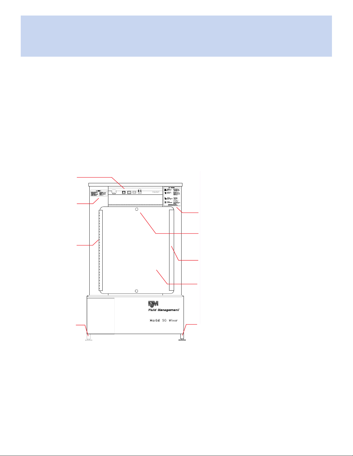
General Locations
• CONTROL PANEL – All controls are in one location.
• DOOR SAFETY SWITCH – The Door must be closed continuously to operate
the paint mixer.
• WARNING STICKERS – Read these important messages for YOUR safety.
• ADJUSTABLE FEET – The leveling feet adjust in order to level the mixer.
Control Panel
Safety Label
Safety Label
Door Safety Switch
Getting to
Know Your
Paint Mixer
Hinge
Door Handle
Adjustable Foot
Figure 1. General Locations
Door
Adjustable Foot
Fluid Management Customer Ser vi ce 1 . 800 . 462 . 2 466
Harbil 5G Mixer | 13
Page 16
Getting to Know Your Paint Mixer
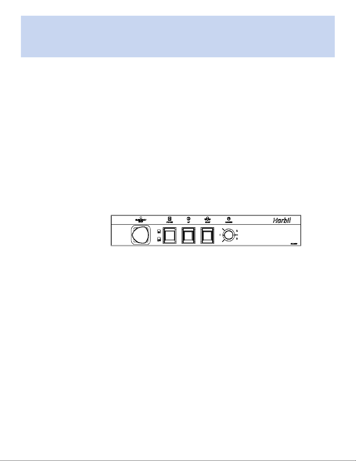
Control Panel
• EMERGENCY STOP button for quickly stopping the mixer.
• POWER rocker switch for applying power to the machine.
• UP button for raising the top pressure plate.
• START button for activating the mixer.
• TIMER for setting the desired mix time from 30 seconds to 3 minutes.
The POWER switch must be in the ON position and the
EMERGENCY STOP must be turned clockwise until it
Note
pops up for the machine to function.
Figure 2. Control Panel
Reversible Door
The door on the mixer can be easily reversed using a slotted screwdriver.
Instructions for reversing the door are found in the maintenance section of this
documentation.
14 | Harbil 5G Mixer
Fluid Management Customer Ser vi ce 1 . 800 . 462 . 2 466
Page 17

Important Information
Before operating the mixer, carefully read the following important information.
Warnings
• Verify that your paint mixer is properly levelled. Improper leveling may cause
severe damage to the machine during the mixing operation.
• Always shut off the master POWER switch and unplug the mixer from the AC
power outlet before servicing the paint mixer.
• THIS MACHINE IS NOT EXPLOSION-PROOF AND MUST NOT BE USED IN
A FLAMMABLE ATMOSPHERE.
Cautions
• Do not run the paint mixer without a container in place.
• Do not mix more than one full case (four 1-gallon cans) of paint at one time.
The maximum weight limit is 80 pounds for paint and 60 pounds for
stucco mixture. See BASIC OPERATION, Figure 3, “Gallon Can
Placement” on page 16.
• On 5-gallon metal containers, use the flake-board disc for recessed bottoms
that do not have a center support. Use the discs for recessed tops.
See BASIC OPERATION, Figure 4, “5-Gallon Container Cut-Away
View” on page 17.
Important
Information
• On 5-gallon plastic containers, use the foam discs for the recessed tops
around the bung hole. Do not use the flake board disc on plastic
containers.
Fluid Management Customer Ser vi ce 1 . 800 . 462 . 2 466
Harbil 5G Mixer | 15
Page 18
Basic Operation
Basic
Operation
Open the door. If you need to raise the top plate to accommodate the container to
be mixed, turn on the POWER switch and push the UP button. Wait a few seconds
until the UP light goes out. This will raise the top plate about two inches. Repeat if
necessary.
To quickly stop the machine, push the EMERGENCY
STOP button. If you open the door during the operation,
Note
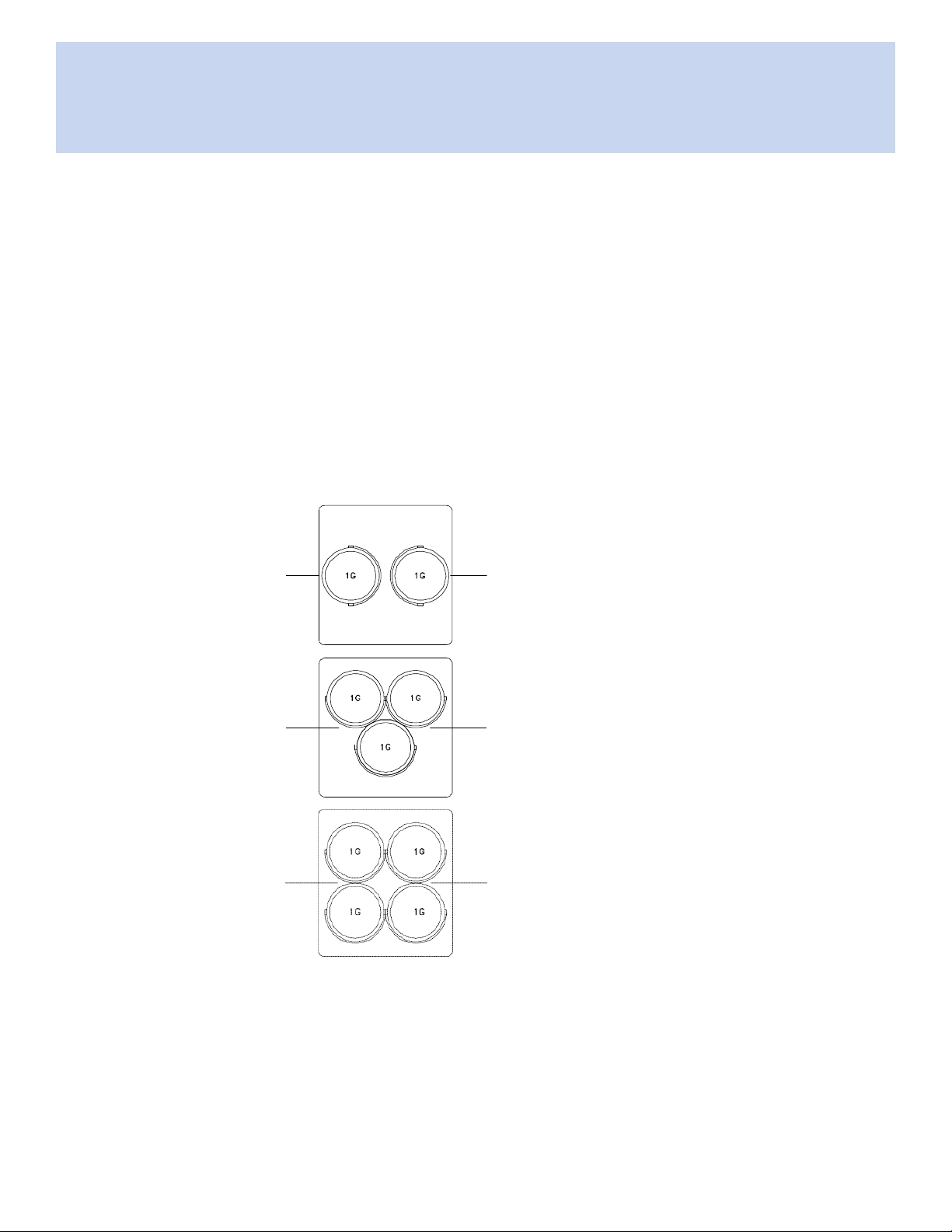
1. After opening the front door, place the container(s) near the center of the
table. The diagram below illustrates the proper gallon can placement.
Cans must be removed from cardboard case before mixing.
the paint mixer will stop.
2 Gallon Cans
Lead Screw Centerline
3 Gallon Cans
Lead Screw Centerline
4 Gallon Cans
Lead Screw Centerline
Figure 3. Gallon Can Placement
16 | Harbil 5G Mixer
Fluid Management Customer Ser vi ce 1 . 800 . 462 . 2 466
Page 19
Basic Operation
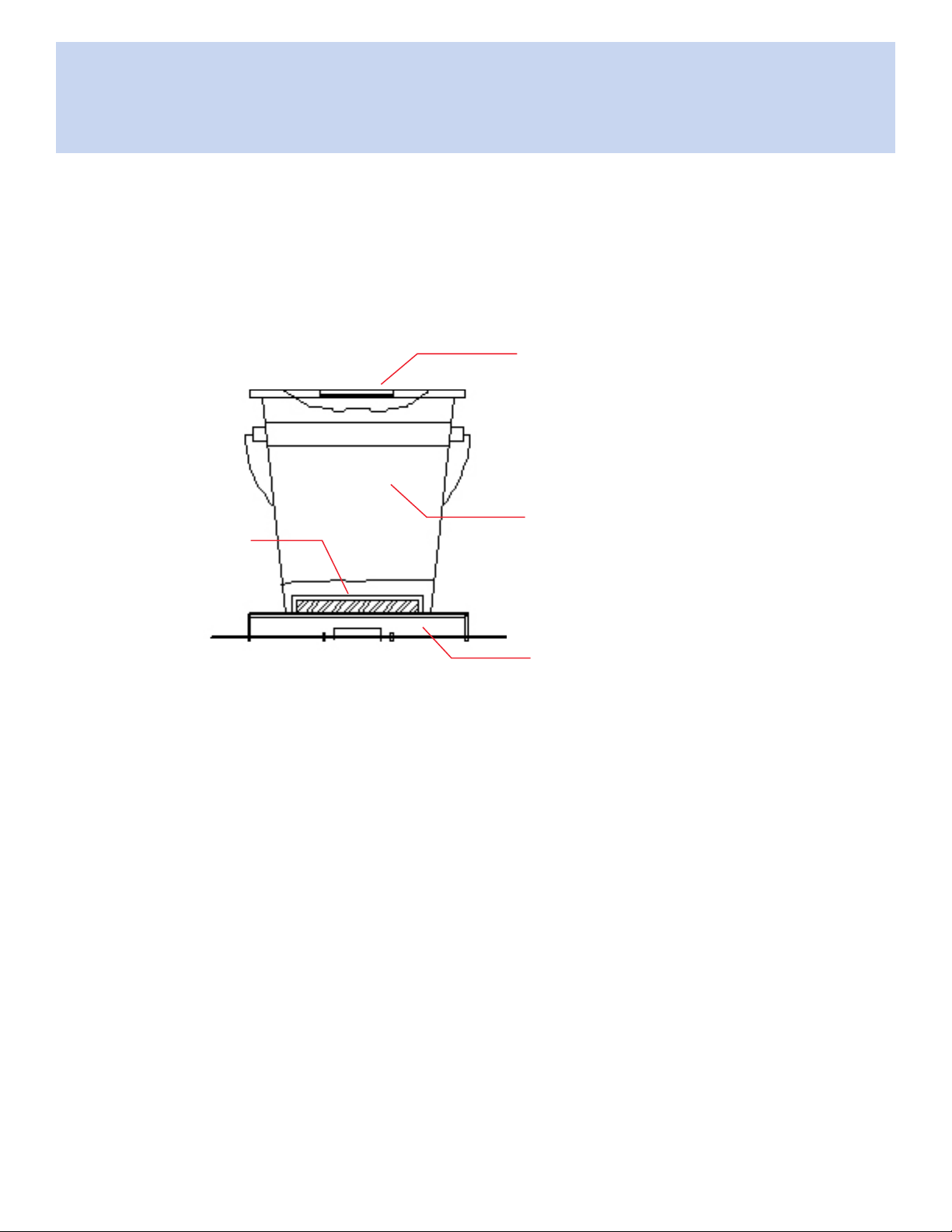
2. When using 5-gallon plastic or metal containers with recessed lids, place the
foam disc on top of the container even with the rim.
Note: Both thick and thin discs come with the mixers. Foam discs
eliminate exing of the container. On metal containers with
recessed bottoms and no center support, place the ake
board disc underneath the container.
Foam Rubber Pad
Used with plastic or metal container.
5 Gallon Container
Flake Board Disk for
metal containers only
Table
Figure 4. 5-Gallon Container Cut-Away View
3. Close the door firmly. The paint mixer will not operate with the door
open.
4. Set the timer on the control panel to the desired shaking time.
5. Apply power to the mixer by pressing the POWER rocker switch to the ON
position and turning the EMERGENCY STOP button clockwise until it pops
out to the ON position. If the button does not turn, then it is already in the
ON position. To stop the paint mixer, depress the EMERGENCY STOP
button.
Fluid Management Customer Ser vi ce 1 . 800 . 462 . 2 466
Harbil 5G Mixer | 17
Page 20

Basic Operation
6. Push the START button. The paint mixer will go through the following
sequence:
• The paint mixer will automatically move the top plate down and hold the
• The paint mixer will shake the container for the set amount of time.
• The paint mixer will raise the top plate about 2 inches. Allow a few
7. Remove the paint container when the mixer is completely stopped.
container in place.
seconds for the top plate to raise.
18 | Harbil 5G Mixer
Fluid Management Customer Ser vi ce 1 . 800 . 462 . 2 466
Page 21

Operational Test
Operational Test Procedure
1. Plug in the mixer.
2. Using two one-gallon containers followed by a five-gallon container, perform
these steps:
• With the one-gallon containers in position on the table, set the TIMER to
its minimum value.
• Twist the EMERGENCY STOP to release it.
• Depress the POWER switch.
• With one hand on the EMERGENCY STOP, depress the START switch.
The unit should cycle automatically—clamping down and starting the
shake cycle with a smooth, vibration-free movement.
3. If vibrations are noticed, immediately press down the EMERGENCY STOP
switch.
• Mildvibrations may occur because the unit is not properly leveled. Try
slipping a piece of paper under each of the four (4) adjustable feet. If
the paper easily slides under a foot (feet), then the mixer is not solidly
contacting the floor. Level as necessary.
Operational
Test
• Severeorpersistentvibrations may be caused by a variety of problems.
Check to make sure that the struts are moving freely. If they are, then
contact a qualified service technician or Customer Service at Fluid
Management for assistance before continuing to operate the mixer.
4. Repeat the above steps using a 5-gallon container.
5. When the unit is operating smoothly, replace and secure the top cover and
upper rear cabinet with the screws.
6. Your high speed paint mixer is now ready for operation. Please read the next
two sections to familiarize yourself with the machine and how to operate it
safely.
Fluid Management Customer Ser vi ce 1 . 800 . 462 . 2 466
Harbil 5G Mixer | 19
Page 22

Maintenance Procedures
Maintenance
Procedures
General Lubrication
To ensure safe, dependable operation of the paint mixer, follow the maintenance
schedule detailed below.
WEEKLY
Lubricate the following items with SAE 20 oil:
• Top pressure plate nut (accessed through the right and left side doors)
• Threaded lead screw (accessed through the front door)
EVERY 3 MONTHS
Lubricate the Super-Struts with SAE 20 oil:
• Apply oil to the Super-Strut pins so that the oil will ow down the bushing.
• Lubricate the struts on the both sides of the mixer.
Grease ange bearings.
EVERY 6 MONTHS
20 | Harbil 5G Mixer
Fluid Management Customer Ser vi ce 1 . 800 . 462 . 2 466
Page 23

Maintenance Procedures
Super-Struts Lubrication
Use the table below to record your maintenance on the Super-Struts every three
months.
LUBRICATION RECORD
Date
Fluid Management Customer Ser vi ce 1 . 800 . 462 . 2 466
Harbil 5G Mixer | 21
Page 24

Troubleshooting
Troubleshooting
PROBLEM CHECK ACTION
The paint mixer does not start.
Using the chart below, locate the problem in the rst column, then select the
probable cause to check and action to take from the next two columns. The
problems are arranged from the simplest to the most complex.
Where appropriate, refer to the Servicing and Repair section to correct the
problem.
if mixer attached to receptacle.
receptacle for voltage.
if front door is not closed.
POWER switch is in the ON
position and operating properly. The
EMERGENCY STOP button should
not be depressed.
6.3 amp fuse.
5 amp Slow-Blow fuse.
• Connect to power source.
• Contact electrician.
• Close the front door.
• Turn on POWER switch. Put the
EMERGENCY STOP button in the
ON position.
• Replace fuse.
• Replace fuse.
The top plate does not move in a
downward direction.
PCB connector.
may be a problem with printed circuit
board.
loose/broken wire in the DC motor
cable.
START switch mechanism on the
control panel for a loose connection.
DC motor.
may be a problem with printed circuit
board.
• Reestablish PCB connector.
• Call Customer Service.
• Replace printed circuit board.
• Reconnect loose wire or replace
broken wire.
• Tighten connections at the START
switch.
• Replace START switch mechanism.
• Using voltmeter, measure voltage at
DC motor or call Customer Service.
• Replace DC motor.
• Call Customer Service.
• Replace printed circuit board.
22 | Harbil 5G Mixer
Fluid Management Customer Ser vi ce 1 . 800 . 462 . 2 466
Page 25

Troubleshooting
PROBLEM CHECK ACTION
The top plate does not move in an
upward direction.
Paint mixer runs before the top plate
clamps on the container.
Paint mixer will not shut off.
voltage at the DC motor.
broken wire in the DC motor cabling.
problem with the DC motor.
problem with the UP switch
mechanism on the control panel.
may be a problem with printed circuit
board.
binding of the top plate.
may be a problem with printed circuit
board.
timer control on the front control
panel.
if relay is stuck in the closed
position.
bad timer.
may be a problem with printed circuit
board.
• Use voltage meter or contact
Customer Service for assistance.
• Replace broken DC motor cabling.
• Contact Customer Service.
• Replace DC motor.
• See wiring schematic and test with
voltmeter.
• Replace the UP switch mechanism.
• Call Customer Service.
• Replace printed circuit board.
• Clean and oil lead screws.
• Call Customer Service.
• Replace printed circuit board.
• Replace if necessary.
• Replace relay.
• Replace timer.
• Call Customer Service.
• Replace printed circuit board.
The shake motor has voltage and
hums, but it will not run.
Fluid Management Customer Ser vi ce 1 . 800 . 462 . 2 466
low line voltage.
V-belt tension.
motor capacitor.
shake motor.
• Confirm that the mixer is on a
dedicated line.
• Correct tension.
• Replace motor capacitor.
• Replace shake motor.
Harbil 5G Mixer | 23
Page 26

Troubleshooting
PROBLEM CHECK ACTION
An excessive amount of vibration
occurs.
START light is on and nothing
happens.
START light is on and the top plate
clamps on the container, but mixer
will not run.
mixer is out of balance.
adjustable leg is broken or
damaged.
broken strut.
DC motor coupling set screw is
loose.
broken wire in the DC motor cabling.
problem with the DC motor.
may be a problem with printed circuit
board.
make sure that the mixer is on a
dedicated line.
if front door closed.
problem is a loose motor coupling
set screw.
• Level by adjusting the legs.
• Replace adjustable leg.
• Replace broken strut.
• Tighten the DC motor coupling set
screw.
• Replace DC motor cable.
• Replace DC motor.
• Call Customer Service.
• Replace printed circuit board.
• Connect to dedicated line.
• Close the door.
• Tighten DC motor coupling set
screw.
The mixer starts slowly and then
increases to normal speed in a few
seconds.
reset button.
loose or broken wire in the shake
motor cabling.
shake motor.
shake motor V-belt tension. • Adjust the shake motor V-belt
• Press blue reset button located on
overload relay.
• Tighten or replace wire.
• Replace shake motor cabling if
necessary.
• Replace wire.
• Contact Customer Service for
assistance.
• Replace the shake motor.
tension.
24 | Harbil 5G Mixer
Fluid Management Customer Ser vi ce 1 . 800 . 462 . 2 466
Page 27

Troubleshooting
PROBLEM CHECK ACTION
The DC motor runs, but the top plate
does not move.
The mixer stops before completing
shake cycle.
The mixer speeds up and slows
down. The START light is blinking.
The mixer crushes or throws cans.
for loose set screw in one of the
DC motor couplings.
key and set screw on timing
gears.
for broken or loose wire in the DC
motor cabling.
if front door is making contact with
the safety switch in the control box.
broken wire in DC motor cabling.
clamping force may be out of
adjustment.
• Tighten set screw(s).
• Tighten key and set screw.
• Replace DC motor cable.
• Adjust safety switch.
• Replace DC motor cable.
• Adjust clamping force as required
Fluid Management Customer Ser vi ce 1 . 800 . 462 . 2 466
Harbil 5G Mixer | 25
Page 28

Servicing and Repair
Servicing and
Repair
General Information
If you do not feel condent about disassembling the paint mixer or replacing a part,
DO NOT ATTEMPT THE PROCEDURE. Should problems or questions arise,
contact Customer Service at Fluid Management.
Carefully read all of the instructions before you begin. For component identication
and location, refer to the Parts Section of this manual.
Safety Procedure
ELECTRICAL HAZARD
Always shut off the POWER switch and unplug the
WARNING
mixer before servicing.
Wear your safety glasses to prevent possible injury.
CAUTION
26 | Harbil 5G Mixer
.
Fluid Management Customer Ser vi ce 1 . 800 . 462 . 2 466
Page 29

Opening the Mixer
Remove Exterior Panels
1. Using a medium-size screwdriver or 1/4” nut driver, remove the sheet metal
screws securing the top cover. Lift it off the mixer.
Top Cover
Control Box Assembly
sheet metal screw
Front Door
Upper Rear Cabinet
Lower Rear Cabinet
(not shown)
Front Cover
(stainless steel)
Right / Left Side Panel
Front Panel
Opening the
Mixer
Figure 5. Removing the Mixer Covers
2. In the same manner, take off the upper rear cabinet (3-sided piece) covering
the sides and back, and set to the side of the work area.
3. If your machine has a 4-sided skirt, remove it now.
4. At the back of the mixer, squeeze the power supply strain relief with a pair of
pliers, and pull it off the cord. Move the back panel away from the machine
(the cord will still be attached).
5. Remove the right and left side panels, and the lower front panel.
6. To prevent damage, remove the mixer door by lifting the door off its pins.
7. Cut the upper wire tie wrap securing the 3 cables to the outer frame at the
left side of the machine.
8. Remove the remaining front sheet metal covering. Carefully prop the front
piece (two front columns with control box assembly) to the side of the
machine, being careful to not damage the cords.
Fluid Management Customer Ser vi ce 1 . 800 . 462 . 2 466
Harbil 5G Mixer | 27
Page 30

Removing Shake Frame
Removing
Shake Frame
Some service procedures involve removing the shake frame. Read all of the
following instructions. If you have any doubt about performing these procedures,
please contact Customer Service at Fluid Management. For component identication
and location, refer to the Parts Section of this manual.
Removing Shake Frame Procedure
1. Remove the sheet metal covers (see OPENING THE MIXER, page 27).
2. To facilitate the reassembly process, mark or prepare a drawing of the
2 wires running from the left side of the terminal block to the control box.
3. Using a small blade screwdriver, disconnect the 2 wires.
4. Pull the cable containing the 2 wires through 2 tie wraps, or snip and remove
the tie wraps with side cutters.
black
black
28 | Harbil 5G Mixer
red
Figure 6. Disconnecting the 4 Wires at the Terminal Block
Fluid Management Customer Ser vi ce 1 . 800 . 462 . 2 466
red
Page 31

Removing Shake Frame
5. Follow the cable to the strain relief, located on the inside of the hole where
the cable goes through the shake frame. Unscrew the strain relief and pull
the cable through the hole into the enclosure.
Inner Frame
to Shake Frame
DC Motor Cable
to Power Box
to Power Box
Shake Motor Cable
Inner Frame
Counter Weights
Figure 7. Removing the Shake Frame
Fluid Management Customer Ser vi ce 1 . 800 . 462 . 2 466
Harbil 5G Mixer | 29
Page 32

Removing Shake Frame
Remove the
Counterweights
The inner frames weigh 21 pounds each!
CAUTION
Remove the Counterweights Procedure
1. Remove the 2 lower inner frame counterweights to access the nuts on the
flange bearings and the rear screws and nuts on the pillow block bearings.
Note: DO NOT REMOVE the 2 upper inner frame counterweights.
Use two 1/2” wrenches, or a ratchet and a 1/2” wrench
to remove the 2 lower nuts and screws holding the lower
weights to the inner frame to allow access to the crankshaft.
2. With two 1/2” wrenches or a ratchet and a 1/2” wrench, loosen BUT DO NOT
REMOVE the 4 screws securing the flange bearings to the shake frame.
Remove the 4 nuts.
30 | Harbil 5G Mixer
Flange Bearing Screw
Figure 8. Flange Bearings
Fluid Management Customer Ser vi ce 1 . 800 . 462 . 2 466
Flange Bearing
washer
Flange Bearing Nut
Page 33

Removing Shake Frame
3. With a 1/8” hex wrench, loosen the 2 set screws holding the crankshaft to
the flange bearings. Remove the flange bearings. If necessary, use a wheel
puller to pry the flange bearing from the crankshaft.
Be careful when removing the shake frame. It may swivel
CAUTION
or fall forward while working on the next step.
Be careful when lifting. The shake frame weighs over 200
pounds.
CAUTION
4. Position one person at the back of the mixer to hold the shake frame. Using
a 1/2” socket or open-end wrench, remove the 2 nuts and screws holding the
swivel rods to the inner frame.
Swivel Rod
hex nuts
athead
cap screws
Shake Frame
Figure 9. Nuts and Screws Holding Swivel Rods
5. Repeat steps 2 – 4 on the other side.
6. With the assistance of another person, lift up and pull out the complete
shake frame.
Fluid Management Customer Ser vi ce 1 . 800 . 462 . 2 466
Harbil 5G Mixer | 31
Page 34

Testing Shake Motor
Testing Shake
Motor
Read all of the following instructions. If you have any doubt about performing these
procedures, please contact Fluid Management.
For component location and identication, refer to the Parts Section of this manual.
ELECTRICAL HAZARD
To carry out this test you will need 120 volts which
WARNING
Testing Shake Motor Procedure
1. Place an empty pail on the table and close the door firmly. Turn on the paint
mixer and push the START button. Give the paint mixer enough time to lower
the top plate onto the pail.
2. Turn off the paint mixer and unplug the electrical cord.
3. Remove the lower front and right side panels.
could cause electrical shock.
4. Remove the motor cover.
5. Take a 3-conductor jumper cable, which has a plug at one end and stripped
wires on the other end, and connect the wires to the shake motor.
6. Plug the jumper cord into a wall outlet (120 volts or appropriate voltage).
• If the shake motor starts to run, then the cable or the relay is bad.
• If the shake motor does not run, it has to be replaced.
7. Unplug and remove the jumper cord from the shake motor.
8. Reassemble the mixer by returning the motor cover and lower panel to their
correct positions.
32 | Harbil 5G Mixer
Fluid Management Customer Ser vi ce 1 . 800 . 462 . 2 466
Page 35

Changing Shake Motor
Read all of the following instructions. If you have any doubt about performing these
procedures, please contact Customer Service at Fluid Management.
Turn to the Parts Section of this manual for component identication and location.
Changing Shake Motor Procedure
1. Unplug the electrical cord.
2. Remove lower front and right/left side panels.
3. Make a drawing of the wire to the terminal connections, then disconnect the
wires from the shake motor.
4. Remove the 4 hold-down screws on the motor.
5. Remove the V-belt from the pulley on the motor.
6. Remove and replace the motor.
7. Remove the pulley from the old motor by loosening the set screw.
Changing
Shake Motor
8. Reposition the wires on the new shake motor by following the drawing made
in Step 3.
9. Reinstall the pulley on the new motor.
10. Put the V-belt on the balance groove pulley, then on the motor pulley.
11. Align the motor pulley with the groove pulley on the crankshaft.
12. Install and tighten down the 4 motor hold-down screws while keeping tension
on the belt.
13. Be sure to adjust the shake motor for proper tension on the V-belt. The
deflection should be approximately 3/16” at 5 pounds of pressure.
14. Reassemble the paint mixer by reversing these instructions.
15. With a paint container in position, perform a test run of the mixer to be sure
that it is operating correctly.
Fluid Management Customer Ser vi ce 1 . 800 . 462 . 2 466
Harbil 5G Mixer | 33
Page 36

Changing the V-Belt
Changing
the V-Belt
Read all of the following instructions. If you have any doubt about performing these
procedures, please contact Customer Service at Fluid Management.
Refer to the Parts Section for component identication and location.
Changing the V-Belt Procedure
1. Unplug the electrical cord.
2. Remove all the sheet metal covers (see OPENING THE MIXER, page 27).
3. Loosen the screws and nuts on the flange bearings.
4. Slide the shake frame away from the right side of the crankshaft.
5. Remove the flange bearing on the right side of the machine.
6. Loosen the shake motor mounting screws and slide the motor toward the
crankshaft, thereby loosening the V-belt. Remove the V-belt.
7. Put the new V-belt on the balance groove pulley, then on the motor pulley.
8. Install and tighten down the 4 motor hold-down screws while keeping tension
on the belt.
9. Be sure to adjust the shake motor for proper tension on the V-belt. The
deflection should be approximately 3/16” at 5 pounds of pressure.
10. Reassemble the paint mixer by reversing these instructions.
34 | Harbil 5G Mixer
Fluid Management Customer Ser vi ce 1 . 800 . 462 . 2 466
Page 37

Removing Circuit Board
Read all of the following instructions. If you have any doubt about performing these
procedures, please contact Customer Service at Fluid Management.
Turn to the Parts Section for component identication and location.
ELECTRICAL HAZARD
The mixer must be unplugged before attempting this
WARNING
Removing Circuit Board Procedure
1. Unplug the electrical cord.
2. Remove the sheet metal screws on the control panel and slowly swing it
down.
3. Remove the push-on type connector at the bottom of the printed circuit
board.
procedure. There is a chance of electrical shock.
Removing
Circuit Board
Pull the connector with alternating left and right force away from the circuit
board. It is not necessary to loosen the screws on the connector.
4. Remove the 4 nuts from the screws that attach the circuit board to the
control panel.
5. Install the new board with the push-on connector.
6. Reinstall the control panel and the top cover.
7. Connect the electrical cord.
Fluid Management Customer Ser vi ce 1 . 800 . 462 . 2 466
Harbil 5G Mixer | 35
Page 38

Installing Rubber Pads
Installing
Rubber Pads
Read all of the following instructions. If you have any doubt about performing these
procedures, please contact Customer Service at Fluid Management.
For component identication and location, consult the Parts Section of this manual.
A special rubber pad is fastened to the top plate to hold cans in place during
operation. When attaching the rubber pad to the upper plate, use P/N 4000327,
Loctite Super Bonder #416 Instant Adhesive. Follow the instructions on the
adhesive for the drying time. Use protective gloves when applying the adhesive.
Installing Rubber Pads Procedure
1. Apply a non-flammable solvent to remove the old adhesive.
2. Apply the permanent adhesive to the pad. Follow the glue pattern shown in
the diagram.
Top Plate Assembly
glue pattern
Figure 10. Glue Pattern
36 | Harbil 5G Mixer
Fluid Management Customer Ser vi ce 1 . 800 . 462 . 2 466
Page 39

Installing Rubber Pads
3. Making sure the pad is positioned properly, attach the pad to the plate and
hold in position for about 2 minutes.
4. Remove the backing from the tape on the replacement lower table and press
into position.
5. After attaching the pads, place four 1-gallon cans on the table.
6. Turn on the mixer. Allow the top plate to lower onto the cans and Turn off the
mixer before it goes into the shaking cycle.
This step is only to press the pads in place during drying of the glue.
DO NOT ALLOW THE MIXER TO SHAKE THE CANS OF PAINT.
7. Unplug the electrical cord as a safety precaution.
8. Allow the adhesive to dry overnight.
9. After the adhesive has dried, open the mixer, remove the cans and test as
appropriate.
At this point, the mixer should be ready for normal operation.
Fluid Management Customer Ser vi ce 1 . 800 . 462 . 2 466
Harbil 5G Mixer | 37
Page 40

Replacing / Adjusting DC Motor
Replacing
/ Adjusting
DC Motor
The DC motor needs adjusting if it is making excessive noise while the top plate is
moving. Adjustments are also required when reinstalling or replacing the motor.
Read all of the following instructions. If you have any doubt about performing these
procedures, please contact Customer Service at Fluid Management.
DC Clamping Motor Replacement/Adjustment
1. Make sure that the power is off.
2. Remove the top cover.
3. If you only need to readjust the DC motor, execute the following steps:
• Loosen the 4 mounting screws that connect the DC motor to the frame.
• Assure that the DC motor is properly aligned and fully tighten the 4
mounting screws.
If you need to replace the motor, go to the next step.
4. Disconnect the red and black motor leads from the terminal block.
5. Remove the 4 screws that connect the DC motor to the shake frame.
6. Loosen the Allen set screw and remove the coupling half from the old motor
and save for later use.
7. Place the coupling half onto the new motor and tighten the set screw.
8. Place the new DC motor in the shake frame while easing the coupling over
the lead screw. DO NOT STRESS THE COUPLING.
9. Insert and tighten the 4 mounting screws.
10. Mount the DC motor coupling onto the lead screw by tightening the set
screw.
11. Connect the red and black motor leads to the terminal block.
12. Replace the top cover.
13. Connect power to the mixer.
14. Execute the operational test.
38 | Harbil 5G Mixer
Fluid Management Customer Ser vi ce 1 . 800 . 462 . 2 466
Page 41

Adjusting Clamping Force
The clamping force needs adjusting if cans are being crushed or thrown from the
shake frame. Adjustments may also be required after changing the control board or
other components in the shake mechanism. The clamping force is specied in the
instructions (P/N 24040) that come with the replacement board. The adjustment kit
(P/N 24041) also comes with the same instructions.
Read all of the following instructions. If you have any doubt about performing these
procedures, please contact Customer Service at Fluid Management.
Refer to the Parts Section for component identication and location.
The optimum clamping force is specied in the instructions (P/N 24040) shipped with
the board. This process should be used to adjust the clamping force to a range within
that target. The range is expressed in terms of an “upper limit” and a “lower” limit.
Both the positioning spacer (P/N 24069) and the gauge (P/N 24124) are required in
executing this process.
Clamping Force Adjustment Procedure
1. Unplug the power cord from the electrical outlet.
2. Remove the 2 screws at the top of the control box and open, exposing the
control circuit board.
Clamping
Force
Adjustment
screws
Shake Relay
Control Board
Control Box
Adjustment
Switch
wire (removed in Step 3
and connected in Step 17
Figure 11. Control Board Location
Fluid Management Customer Ser vi ce 1 . 800 . 462 . 2 466
Harbil 5G Mixer | 39
Page 42

Adjusting Clamping Force
3. Remove the wire from the upper left terminal of the shake relay.
4. On the control board, set the adjustment switch to position number 2.
5. Plug the power cord back into the electrical outlet.
6. Assure that the E-Stop button is released and press the power ON switch.
7. Press the UP button on the control box.
8. Open the door and place the positioning spacer (P/N 24096) and gauge
(P/N 24124) on the bottom plate against the back lip as shown.
Back Lip
4-5/8”
Figure 12. Gauge Position
Note: Position is critical. Use the positioning spacer. Be sure the
gauge is centered and 4-5/8” from the back lip.
9. Press the START button. The top plate will clamp the gauge without going
into the shaking cycle.
Positioning
Spacer
Gauge
Bottom Plate
40 | Harbil 5G Mixer
WARNING
If wire was not removed in step #3, the mixer will
shake, possibly causing damage or injury.
Fluid Management Customer Ser vi ce 1 . 800 . 462 . 2 466
Page 43

Adjusting Clamping Force
10. After clamping, read and record the force on the gauge.
11. Place the power switch in the OFF position, wait about 5 seconds and return
it to the ON position.
12. Press the UP button.
13. If the force is at the lower limit or less, change the adjustment switch to the
next lowest number and go to step #9.
Note: If the force is at the “upper limit” or greater, change the
adjustment switch to the next highest number and go to
step #9. If the force falls within the target, go to the next
step.
14. Press the power OFF switch.
15. Remove the gauge and spacer.
16. Unplug the power cord from the electrical outlet.
17. Place the wire back on the upper left terminal on the shake relay.
18. Close the control box and insert the screws.
19. Plug the power cord into the electrical outlet.
At this point, the mixer is ready for normal operation.
Fluid Management Customer Ser vi ce 1 . 800 . 462 . 2 466
Harbil 5G Mixer | 41
Page 44
Reversing Door
Reversing Door
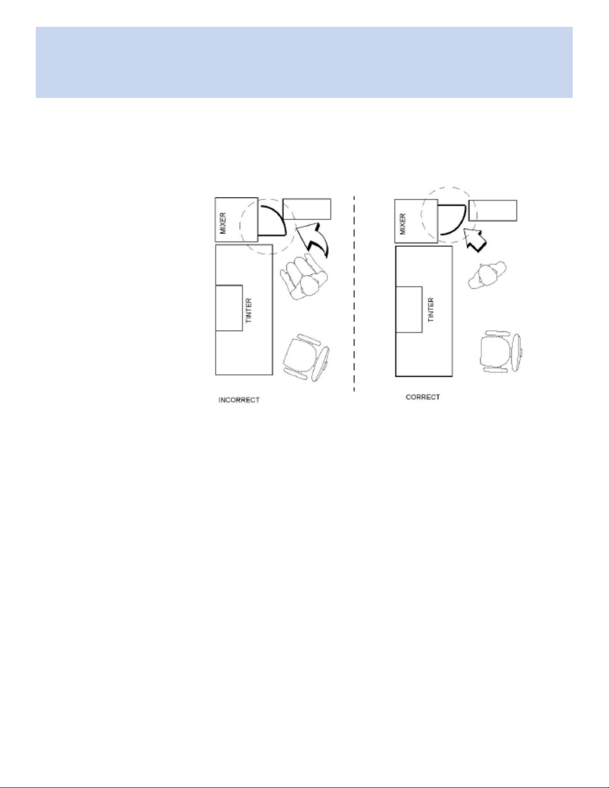
The front door can be reversed to accommodate any space plan. Some layouts lend
themselves to a front door that opens with the handle on the left. Others require that
the door open in the reverse of this. The mixer is shipped with the door handle on the
right side.
Figure 13. Floor Plans
The following steps represent the process by which the front door is reversed.
Reversing Door Procedure
1. Unplug the power cord from the electrical outlet.
2. Open the door.
3. Using two 3/8” wrenches, relocate the stud at the top of the door to the hole
at the bottom of the door.
Note: If the stud is not relocated properly, the mixer will not
operate.
42 | Harbil 5G Mixer
Fluid Management Customer Ser vi ce 1 . 800 . 462 . 2 466
Page 45

Reversing Door
Figure 14. Reversing Door
4. Using a slotted screw driver, remove the 4 screws that mount the door to the
mixer. Save for later use.
5. Reach behind the door post and remove the 2 magnets by pressing the tabs.
6. Insert these magnets in the slots on the opposite door post.
7. Position the door with the stud at the top and mount on the door post using
the screws that were removed earlier.
8. Close the door.
9. It may be necessary to adjust the safety switch at the top of the door near
the stud. You should hear a clicking sound as the door is opened and closed.
Side- to-side adjustments are done with a slotted screw driver.
Figure 15. Safety Switch Adjustment
Fluid Management Customer Ser vi ce 1 . 800 . 462 . 2 466
Harbil 5G Mixer | 43
Page 46

Replacing Super-Struts
Replacing
Super-Struts
Read all the directions carefully. If you do not feel comfortable disassembling the
mixer or replacing a part, do not attempt the procedure. Refer to the Parts Section
for component identication and location.
Removing the External Panels
1. Unplug the electrical cord.
2. Remove the top cover and lift it off the mixer.
3. Remove the upper rear cabinet (3-sided piece), front cover, and right and left
side panels (see Figure 5, “Removing the Mixer Covers” page 27).
4. Set the covers to the side of the work area.
Removing the Super-Struts
1. Locate the 4 Super-Struts to be replaced. You will be replacing the struts
on one side at a time.
44 | Harbil 5G Mixer
Strut
Strut
Figure 16. Locating the Struts
Fluid Management Customer Ser vi ce 1 . 800 . 462 . 2 466
Page 47

Replacing Super-Struts
2. Locate the hole in the strut pin. Insert the end of the 1/8” hex key into the
hole to prevent the pin from rotating while loosening the bolt. If no hole is
observed, grasp the pin with vice grips and loosen the nut.
hex wrench
Figure 17. Keeping the Strut Pin from Rotating
3. Beginning on the right side, use a box end or adjustable wrench to remove
the top nuts, washers, and rubber grommets on both struts. Remove the hex
wrench from the hole in the strut pin.
Fluid Management Customer Ser vi ce 1 . 800 . 462 . 2 466
Harbil 5G Mixer | 45
Page 48

Replacing Super-Struts
4. Using the 2” x 4’ wooden board for leverage, lift the shake frame in the center
until the 2 strut pins are raised high enough to clear the strut bodies.
46 | Harbil 5G Mixer
Figure 18. Lifting the Inner Frame
5. Have a second person place three 2” x 4” blocks under the front and rear
inner frame for support as shown below.
6. Remove both strut pins, bodies, and springs from the frame.
Fluid Management Customer Ser vi ce 1 . 800 . 462 . 2 466
Page 49

Replacing Super-Struts
Installing the Super-Struts
Refer to the Super-Strut assembly drawing for parts locations.
Figure 19. Super-Strut Assembly
1. Beginning with the REAR strut install the new strut body, washers, rubber
grommets, and bottom screw on the outer frame.
Note: When installing the rubber grommets, the two shouldered
ends must face each other with the mounting bracket
between them as shown in Figure 21, “Replacing the Front
Strut” on page 49.
2. Hand tighten until snug.
Fluid Management Customer Ser vi ce 1 . 800 . 462 . 2 466
Harbil 5G Mixer | 47
Page 50

Replacing Super-Struts
3. Repeat Step 1 for the FRONT strut. Install the new strut pins, washers,
rubber grommets, and top nuts on the inner frame as shown in the gure
below. Hand tighten until snug.
48 | Harbil 5G Mixer
Figure 20. Replacing the Front Strut
4. Using the 2” x 4’ board, lift the inner frame and install both springs on the
strut bodies, then remove the blocks from under the inner frame.
5. Lift the inner frame again with the 2” x 4’ board as a lever. This will allow you
to align and insert the strut pins into the strut bodies.
Note: Use care when installing the pins in order to prevent damage
to the inner bushing.
Fluid Management Customer Ser vi ce 1 . 800 . 462 . 2 466
Page 51

Replacing Super-Struts
6. Make sure that the springs are centered. Push with your thumb to click them
into place.
Strut Grommet
Strut Pin
Figure 21. Replacing the Strut Shafts
7. Beginning with the FRONT strut, tighten the top nut until the bottom rubber
grommet is compressed 1/2”.
8. Tighten the BOTTOM screw until the top rubber grommet is also
compressed to 1/2”.
9. Moving to the REAR strut, tighten the TOP nut until the bottom rubber
grommet is compressed 1/2”.
10. Insert the 1/8” hex wrench into the strut pin and tighten the BOTTOM screw
until the top rubber grommet is compressed to 1/2”. Remove the hex wrench
from the strut pin.
11. To change the struts on the other side of the mixer, repeat these steps
beginning with Step 1 under “Removing the Super-Struts”, page 44.
Fluid Management Customer Ser vi ce 1 . 800 . 462 . 2 466
Harbil 5G Mixer | 49
Page 52

Replacing Crankshaft
Replacing
Crankshaft
Please read all the directions before attempting this procedure. If you do not feel
comfortable about disassembling the mixer or replacing a part, please do not attempt
it. Should questions arise, contact Customer Service at Fluid Management.
Turn to the Parts Section for component identication and location.
Access the Crankshaft
1. Unplug the electrical cord.
2. Remove the sheet metal covers. Refer to “OPENING THE MIXER”, page 27.
3. Remove the shake frame and counterweights. Refer “REMOVING SHAKE
FRAME” on page 27.
Remove the Crankshaft
1. Using two 1/2” wrenches, loosen the 4 nuts and screws holding the motor to
the inner frame.
Pillow Block
Bearing Screws
Motor Mounting
Screws and Nuts (4)
Figure 22. Removing the Crankshaft
50 | Harbil 5G Mixer
Fluid Management Customer Ser vi ce 1 . 800 . 462 . 2 466
Page 53

Replacing Crankshaft
2. Remove the old V-belt.
3. Remove and discard the 4 pillow-block screws holding the crankshaft.
4. Remove and discard the old crankshaft assembly.
Install the New Crankshaft
1. The mounting surfaces must be flat before installing the new
assembly.
2. Set the new crankshaft assembly onto the pillow-block mounting pads.
Facing the back of the machine, look at the V-groove balance-plate pulley. It
should be on your left. Adjust, if necessary.
3. Install the new crankshaft assembly with new washers, nuts and 7/16-14” hex
screws. Drop these into position, but do not tighten at this time.
4. Align the pillow blocks over the crankshaft mount. It may be necessary
to remove the motor in order to align, then tighten, the screws on the
crankshaft. If so, follow these steps:
• Lift the front of the machine with the 2” x 4’ wooden board and place the
blocks under the board.
• Remove the 4 hold-down screws on the motor.
• Move the motor out of the way.
5. Align the crankshaft assembly assuring that it is parallel to the rear surface
of the inner frame. Measure the distance between the inner frame weights
and the rear edge of the crankshaft. The measurement on each side of the
crankshaft should be the same.
6. First tighten the front nuts and screws; then tighten the others.
7. Remove the old motor pulley with a hex wrench and a wheel puller.
8. Install the new pulley using the old square key. Do not tighten the pulley set
screw at this time.
9. Reinstall the motor, if it was moved.
Fluid Management Customer Ser vi ce 1 . 800 . 462 . 2 466
Harbil 5G Mixer | 51
Page 54

Replacing Crankshaft
10. Inspect the V-belt and replace if necessary. Check the alignment of the belt
and the pulleys. Now tighten the pulley set screw on the motor pulley.
IMPORTANT Adjust the belt tension to approximately 3/16”
deection at 5 pounds of pressure before tightening
the motor screws.
3/16” deection
Figure 23. Measuring 3/16” Deection
11. Tighten the 4 mounting screws on the motor while applying tension to the
V-belt.
52 | Harbil 5G Mixer
Fluid Management Customer Ser vi ce 1 . 800 . 462 . 2 466
Page 55

Reassembling Mixer
Two people are required to lift the shake frame into the mixer.
Reassembling Mixer Procedure
1. With one person on each side of the shake frame, lift the shake frame into
the mixer and rest it on the crankshaft.
Note: The 4 screw holes in the swivel rods must be properly
aligned with the holes in the inner frame. The second person
supports the top of the shake frame so it will no fall forward.
2. Place the washers on the screws and insert them into the swivel rods. Guide
the screws into the holes in the inner frame.
Note: The screws are inserted from the inside of the swivel rods.
3. Place the nuts on the screws, but do not tighten them all the way. Repeat
steps #2 and #3 on the other side of the mixer.
4. Before mounting the flange bearings, lubricate them with lithium-based
grease.
• Rotate the collar of the flange bearing so that the 2 set screws are facing
up, then place the flange bearing on the end of the crankshaft.
Reassembling
Mixer
• Tighten the set screws holding the crankshaft to the flange bearing.
• Use the 2” x 4’ board to lift the shake frame in order to tighten the 4 nuts
securing the flange bearing to the shake frame.
• Insert the screws from the inside of the shake frame, then place the
washers and nuts on the outside of the flange bearing and hand tighten.
5. Standing in front of the mixer, verify that the shake frame is centered inside
the inner frame. There must be equal clearance between the shake frame
and the inner frame on both sides of the mixer. Adjust if necessary.
6. Tighten the 4 nuts and screws holding the swivel rods to the inner frame.
Insert the wrench on the inner side of the shake frame and tighten one screw
on the right and left sides. Again verify that the shake frame is properly
centered before tightening the other 3 nuts all the way on each side of the
mi xer.
7. Reinstall the inner frame weights.
Fluid Management Customer Ser vi ce 1 . 800 . 462 . 2 466
Harbil 5G Mixer | 53
Page 56

Reassembling Mixer
8. Thread the grey control box cable through the hole in the shake frame and
through the tie wraps. If the tie wraps were removed, install new ones.
9. Tighten the strain relief.
10. Using your wiring diagram, connect the 4 wires leading from the grey cable
to the shake frame terminal block.
11. Reposition the sheet metal covering and secure with the sheet metal screws.
If using a ratchet, do not apply too much pressure to the self-drilling sheet
metal screws.
12. Place the door in its proper position.
13. Secure the top cover.
Test Procedure
1. Push the shake frame vertically and horizontally back and forth to verify
freedom of motion.
2. Plug in the mixer.
3. Place a gallon can of paint in the mixer.
4. Turn on the mixer to verify that it is working properly. Make any necessary
adjustments.
5. Dispose of remaining used parts.
54 | Harbil 5G Mixer
Fluid Management Customer Ser vi ce 1 . 800 . 462 . 2 466
Page 57

Parts
This section is designed to assist you in:
• Performing service functions
• Identifying parts.
ALL REPAIRS MUST BE PERFORMED BY FMDIRECT OR AUTHORIZED FLUID
MANAGEMENT SERVICE TECHNICIAN.
IMPORTANT
Part numbers change from time to time; therefore, call Fluid Management Customer
Service at 1-800-462-2466 to verify part numbers before placing an order. This is
particularly important for machines built prior to 6/95. Some parts are shipped with
installation instructions when appropriate.
Parts Section
Fluid Management Customer Ser vi ce 1 . 800 . 462 . 2 466
Harbil 5G Mixer | 55
Page 58

Parts
Sheet Metal and Outer Frame
Sheet Metal
and Outer
Frame
56 | Harbil 5G Mixer
Fluid Management Customer Ser vi ce 1 . 800 . 462 . 2 466
Page 59

Parts
Sheet Metal and Outer Frame
PARTS NO DESCRIPTION NO REG
A 17221 FRONT DOOR MAGNET, 5G 2
B 17475 STUD 1
C 36586 CONTROL BOX ASSEMBLY, 5G COMPLETE 1
D 24024 RIGHT COLUMN, 5G 1
E 24026 LEFT COLUMN, 5G 1
F 24029 DOOR, 5G 1
G 24030 HINGE 1
H 24031 HANDLE 1
I 4000027 NUT, HEX (NO. 10-32 W/ NYLON PATCH, PACKAGE OF 12) P/N 4000419 8
J 4000047 SCREW, SOCKET HEAD CAP (NO. 10-32 X 1/2") 8
K 4000199 NUT, 10-24 1
L 4000214 SCREW, SELF DRILLING HEX SHEET METAL (NO. 8 X 1/2") 53
M 4980007 DECAL, NOTICE - “OPERATING INSTRUCTIONS” 1
N 4980010 DECAL, WARNING - “WARNING AND CAUTION” 1
O 5101000 OUTER FRAME (ONLY), 5G 1
P 5105104 CABINET (UPPER REAR), 5G 1
Q 5105105 LOWER REAR PANEL, 5G 1
R 5105106 SIDE PANEL (RIGHT AND LEFT), 5G 2
S 5105134 FRONT COVER (STAINLESS STEEL), 5G 1
T 5105135 TOP COVER, 5G 1
30910 TOP COVER, 5G (CUSTOMER SPECIFIC) 1
U 5105105 FRONT PANEL, (REAR) 5G 1
V 5105139 FRONT PANEL, (LOWER) 5G 1
W 5108334 INCOMING CORD, 16 FEET 1
24032 DOOR ASSEMBLY, COMPLETE 1
5308214 DOOR SAFETY LIMIT SWITCH (NOT SHOWN) 1
4700510 5G INSTRUCTION MANUAL (NOT SHOWN) 1
Fluid Management Customer Ser vi ce 1 . 800 . 462 . 2 466
Harbil 5G Mixer | 57
Page 60

Parts
Sheet Metal and Outer Frame
58 | Harbil 5G Mixer
Fluid Management Customer Ser vi ce 1 . 800 . 462 . 2 466
Page 61

Parts
Sheet Metal and Outer Frame
PARTS NO DESCRIPTION NO REG
A 4000126 NUT, HEX (5/16-18, W/ NYLON PATCH, PACKAGE OF 12) P/N 4000441) 20
B 4000127 SCREW, HEX HEAD CAP (5/16-18 X 1-1/4"PACKAGE OF 12) P/N 4000442) 8
C 4000182 PLAIN WASHER, 11/32" ID X 5/8" OD 16
D 5106023 FLANGE BEARING ASSEMBLY, COMPLETE, 5G 2
CRANKSHAFT ASSEMBLY, COMPLETE, 5G (INCLUDES CRANKSHAFT,
E 5106300
F 5102110 INNER FRAME (ONLY), 5G 1
5103182 SHAKE FRAME, 5G COMPLETE 1
G 5107009 SWIVEL ROD ASSEMBLY 2
H 5109006 LEVELING FOOT ASSEMBLY, 5G 4
I 5109220 SUPER-STRUT SHOCK ASSEMBLY 4
COUNTERWEIGHTS, BALANCE PLATE, COUNTERWEIGHT BALANCE PULLEY
AND PILLOW BLOCK BEARINGS)
1
Fluid Management Customer Ser vi ce 1 . 800 . 462 . 2 466
Harbil 5G Mixer | 59
Page 62

Parts
Control Box Assembly
Control Box
Assembly
60 | Harbil 5G Mixer
Fluid Management Customer Ser vi ce 1 . 800 . 462 . 2 466
Page 63

Parts
Control Box Assembly
PARTS NO DESCRIPTION NO REG
A 87140035RH PCB ASSEMBLY 1
B 36586 CONTROL BOX ASSEMBLY 1
C 4000012 SCREW, PAN HEAD CAP (6-32 X 5/16, SLOT) 2
D 4000093 SCREW, PAN HEAD CAP, (6-32 X 1.25, SLOT) 2
E 21320 HEX NUT (6-32 KEPS) 8
F 4000017 LOCK WASHER (#6 EXT. TOOTH) 4
G 81501028RH CIRCUIT BREAKER (10 AMP) 1
H 4000287 FUSE HOLDER 1
I 4000094 HEX NUT (6-32 NYLOCK) 2
J 02331 PLAIN WASHER (#6 SAE) 6
K 4000111 NUT (#8 SPEED) 2
L F005006012 TINNERMAN NUT (6-32 U-TYPE) 2
M 21321 HEX NUT (#8 KEPS) 10
N 87635001RH WIRING HARNESS, LOW VOLTAGE 1
O 5108199 PCB SUPPORT SPACER 4
P 5108210 TRANSFORMER 2
Q 00058 LOCK WASHER (EXT. TOOTH) 4
R 00042 SCREW, PAN HEAD CAP (8-32 X 3/8, PHILLIPS) 4
S 5608204 POWER RELAY 1
T 5608205 SHAKE MOTOR RELAY 1
U 80307412RH TERMINAL BLOCK 1
V 01004 SHEET SCREW (#10 X 3/4, HEX, SLOT) 2
W 00071 SCREW, ROUND HEAD CAP (6-32 X 3/8, SLOT 4
X 80600022RH E-STOP MOUNTING ASSEMBLY 1
Y 80700022RH E-STOP BUTTON 1
Z 83220149RH ON/OFF SWITCH 1
AA 83220019RH UP SWITCH 1
BB 83220049RH START SWITCH 1
CC 87300648RH CAPACITOR 1
DD 82710106RH POTENTIOMETER 1
EE 36589 LABEL 1
FF 1007234 FUSE, 5 AMP, FAST BLOW 1
GG 87635002RH WIRING HARNESS, AC VOLTAGE 1
HH 83200022RH E-STOP SWITCH 1
II 80225022RH POTENTIOMETER KNOB 1
JJ F0116C0603 SET SCREW (6-32 X 3/16) 1
Fluid Management Customer Ser vi ce 1 . 800 . 462 . 2 466
Harbil 5G Mixer | 61
Page 64

Parts
Inner Frame
Inner Frame
62 | Harbil 5G Mixer
Fluid Management Customer Ser vi ce 1 . 800 . 462 . 2 466
Page 65

Parts
Inner Frame
PARTS NO DESCRIPTION NO REG
A 4000126 NUT, HEX (5/16-18, W/ NYLON PATCH, PACKAGE OF 12, P/N 4000441) 8
4000127
B 4000179 PLAIN WASHER, 5/16" ID X 5/8" OD 8
C 4000207 SCREW, HEX HEAD CAP (1/2-13 X 1-3/4") 4
D 4000208 NUT, HEX (1/2-13, WITH NYLON PATCH) 4
E 4000212 PLAIN WASHER, 17/32" ID X 1-1/8" OD 4
F 4000215 SCREW, HEX HEAD CAP (5/16-18 X 3-1/2") 4
G 5102015 INNER FRAME COUNTERWEIGHT (1" X 3-1/2" X 2-11/16" LONG) 4
H 5102110 INNER FRAME (ONLY), 5G 1
I 5106300
J 5108332 DC MOTOR CABLE (4 CONDUCTOR, 48-1/2" LONG) 1
SCREW, HEX HEAD CAP (5/16-18 X 1-1/4",PACKAGE 12, P/N 4000442) (NOT
SHOWN)
CRANKSHAFT ASSEMBLY, COMPLETE, 5G (INCLUDES CRANKSHAFT,
COUNTERWEIGHTS, BALANCE PLATE, COUNTERWEIGHT BALANCE PULLEY
AND PILLOW BLOCK BEARINGS - 5G)
4
1
K 5108405 SHAKE MOTOR V-BELT, 5G (4L330) 1
L 5108406 SHAKE MOTOR SUPPORT BRACKET, 5G 2
M 5108415 SHAKE MOTOR CABLE (3 CONDUCTOR, 66" LONG) 1
N 5108416
O 5108504 SHAKE MOTOR PULLEY, 5G (2.6” OD) 1
SHAKE MOTOR ASSEMBLY, 5G (3/4 HP - 1725 RPM) INCLUDES SHAKE MOTOR
PULLEY AND SHAKE MOTOR CABLE
1
Fluid Management Customer Ser vi ce 1 . 800 . 462 . 2 466
Harbil 5G Mixer | 63
Page 66

Parts
Shake Frame
Shake Frame
64 | Harbil 5G Mixer
Fluid Management Customer Ser vi ce 1 . 800 . 462 . 2 466
Page 67

Parts
Shake Frame
PARTS NO DESCRIPTION NO REG
A 4000077 NUT, HEX (3/8-16, WITH NYLON PATCH (TABLE MOUNTING SCREWS) 12
B 4000087
C 4000096
4000170 SCREW, 5/16”-18 X 3/4”, NYLOC (NOT SHOWN)
D 4000175 SCREW, 1/4-20 X 1/2”, FLAT HEAD 2
E 5103113 TOP PLATE CHANNEL 1
F 5103114 LEAD SCREW BEARING MOUNTING PLATE
G 5103116 TOP BOX (12/31/96 OR LATER) 1
H 5103123 SWIVEL ROD BRACKET 2
I 5103141 SHAKE FRAME SIDE (LEFT & RIGHT) 1(2)
J 5103142 DC MOTOR/GEARBOX ASSEMBLY (1/17/97 OR LATER) 1
SCREW, PAN HEAD (3/8-16, WITH NYLON PATCH (4 - DC MOTOR MOUNTING
SCREWS AND 4 - SWIVEL ROD MOUNTING PACKAGE OF 12, P/N 4000435
NUT, HEX (1/4-20, WITH NYLON PATCH, 4-LEAD SCREW BEARING, 4 SWIVEL
ROD, AND 4-TOP PLATE MOUNTING SCREWS, PACKAGE OF 12, P/N 4000438
4
8
5103147 SHAKE FRAME SIDE, RIGHT (NOT SHOWN) 1
K 23783 SHAKE FRAME TABLE PLATE
L 5103158 PLAIN WASHER, 13/32" ID X 3/4" OD (TABLE MOUNTING SCREWS) 12
M 5103175 TABLE PLATE 1
N 5107009 SWIVEL ROD ASSEMBLY, 5G 2
O 5107123 TOP PLATE RUBBER PAD, 5G (REQUIRES ADHESIVE, P/N 4000327) 1
P 4000370 SCREW
Q 23896 BRACKET
4000327 LOCKTITE SUPER BONDER NO. 416 INSTANT ADHESIVE (1-OZ BOTTLE 1
Fluid Management Customer Ser vi ce 1 . 800 . 462 . 2 466
Harbil 5G Mixer | 65
Page 68

Parts
Shake Frame
66 | Harbil 5G Mixer
Fluid Management Customer Ser vi ce 1 . 800 . 462 . 2 466
Page 69

Parts
Shake Frame
PARTS NO DESCRIPTION NO REG
A 4000002
B 4000087
C 4000096
D 4000128 PLAIN WASHER, 1/4” (2-DC MOTOR COUPLING HALF & 4-LEAD SCREW 6
E 4000145 SCREW, SOCKET HEAD CAP, NO. 10-32 X 1-1/2" (DC MOTOR COUPLING 2
F 4000204
G 4000370
H 5103104 THRUST BEARING 2
LOCK WASHER, 1/4", SPLIT (4 DC MOTOR MOUNTING SCREWS AND 4 TOP PLAT
ASSEMBLY MOUNTING SCREWS)
SCREW, PAN HEAD (3/8-16, WITH NYLON PATCH (4 DC MOTOR MOUNTING
SCREWS AND 4 SWIVEL ROD MOUNTING) AVAILABLE ONLY IN PACKAGE OF 12,
P/N 4000435
NUT, HEX 1/4-20, WITH NYLON PATCH, (4-LEAD SCREW BEARING, 4 SWIVEL
ROD, AND 4-TOP PLATE MOUNTING SCREWS) AVAILABLE ONLY IN PACKAGE OF
12 P/N 4000438
SCREW, SET, NO. 10-32 X 1/2", CUP POINT SOCKET (TIMING BELT PULLEY SET
SCREW)
SCREW, HEX HEAD CAP, 5/16-18 X 3/4", WITH NYLON PATCH (SHAKE FRAME
ASSEMBLY SCREWS)
8
8
12
2
20
I 5103106 FLANGED BUSHING 2
J 5103109 TIMING GEAR 2
K 5103111 LEAD SCREW PILLOW BLOCK BEARING 2
L 5103125 WASHER, LOWER LEAD SCREW 2
M 5103131 SCREW, CARRIAGE (1/4-20 X 1") 4
N 23364 DC MOTOR ASSEMBLY 1
O 5103145 LEAD SCREW TOP PLATE NUT 2
P 5101003 COUPLING SPIDER 1
Q 5103160 LEAD SCREW ASSEMBLY (12/31/96) 2
R 5107004 COUPLING, GEAR BOX 1
S 5107005 COUPLING, LEAD SCREW 2
T 5107014 KEY, TIMING GEAR (LEFT TIMING GEAR - 1/8" X 1/8" X 3/4" LONG) 1
U 5107015 KEY, TIMING GEAR (RIGHT TIMING GEAR - 1/8" X 1/8" X 1-1/4" LONG) 1
V 5107016 TIMING GEAR BELT, 5G 1
W F0131A06B10 SET SCREW, M6 X 1 X 10 1
5107001 COMPLETE COUPLER ASSEMBLY
Fluid Management Customer Ser vi ce 1 . 800 . 462 . 2 466
Harbil 5G Mixer | 67
Page 70

Parts
Shake Frame
68 | Harbil 5G Mixer
Fluid Management Customer Ser vi ce 1 . 800 . 462 . 2 466
Page 71

Parts
Shake Frame
PARTS NO DESCRIPTION NO REG
23784 BOTTOM PAD ASSEMBLY, COMPLETE, 5G 1
A 4000126
B 4000182 PLAIN WASHER (11/32" ID X 5/8" OD) 8
C 5103126
D 5103161 SCREW, CARRIAGE (5/16-18 X 1) 8
E 5103156 TABLE ASSEMBLY, COMPLETE, 5G (INCLUDES STAINLESS STEEL TABLE COVER) 1
F 5106023
G 5106017 BEARING
NUT, HEX (5/16-18, WITH NYLON PATCH) SHAKE FRAME ASSEMBLY SCREWS,
PACKAGE OF 12, P/N s4000441
SCREW, ROUND HEAD RIBBED NECK, 3/8-16 X 7/8" (TABLE MOUNTING
SCREWS)
FLANGE BEARING ASSEMBLY (INCLUDES PLATE, BEARING AND MOUNTING
HARDWARE
8
12
2
Fluid Management Customer Ser vi ce 1 . 800 . 462 . 2 466
Harbil 5G Mixer | 69
Page 72

Parts
Clamping Motor Assembly
Clamping
Motor
Assembly
70 | Harbil 5G Mixer
Fluid Management Customer Ser vi ce 1 . 800 . 462 . 2 466
Page 73

Parts
Clamping Motor Assembly
PARTS NO DESCRIPTION NO REG
A 4000117 SCREW, 4-40 X 3/4” 2
B 4000118 NUT, 4-40 X 3/4”, NYLOC 2
4000096 NUT, HEX (1/4-20, WITH NYLON PATCH PACKAGE OF 12, P/N 4000438) 8
C 5108311 3-POSITION TERMINAL BLOCK 1
D 5103116 TOP BOX
E 5103142 DC CLAMPING MOTOR 1
Fluid Management Customer Ser vi ce 1 . 800 . 462 . 2 466
Harbil 5G Mixer | 71
Page 74

Parts
Top Plate Assembly
Top Plate
Assembly
72 | Harbil 5G Mixer
Fluid Management Customer Ser vi ce 1 . 800 . 462 . 2 466
Page 75

Parts
Top Plate Assembly
PARTS NO DESCRIPTION NO REG
A 4000002 LOCK WASHER, 1/4”, SPLIT 4
B 4000096 NUT, HEX (1/4-20, WITH NYLON PATCH, PACKAGE OF 12, P/N 4000438) 4
C 4000203 SCREW, FLAT HEAD CAP (1/4-20 X 1", SOCKET) 4
D 5103113 TOP PLATE CHANNEL, 5G 1
E 5107123 TOP PLATE RUBBER PAD, 5G 1
F 5103175
4000327
TOP PLATE ASSEMBLY, COMPLETE, 5G (INCLUDES TOP PLATE AND RUBBER
PAD
LOCKTITE SUPER BONDER NO. 416 INSTANT ADHESIVE (1 OZ. FOR RUBBER
PAD) (NOT SHOWN)
1
1
Fluid Management Customer Ser vi ce 1 . 800 . 462 . 2 466
Harbil 5G Mixer | 73
Page 76

Parts
Crankshaft Assembly
Crankshaft
Assembly
74 | Harbil 5G Mixer
Fluid Management Customer Ser vi ce 1 . 800 . 462 . 2 466
Page 77

Parts
Crankshaft Assembly
PARTS NO DESCRIPTION NO REG
A 4000209 SCREW, SET (1/4 - 20 X 3/4”, SOCKET) 8
B 4000210 SCREW, SET (5/16 - 18 X 3/4”, SOCKET) 2
C 4000212 PLAIN WASHER, 17/32” ID X 1-1/8” OD 8
D 5106014
E 5106101 CENTRIFUGAL COUNTERWEIGHT, 5G 1
F 5106105 CRANKSHAFT (ONLY), 5G 1
G 5106107 CRANKSHAFT PILLOW BLOCK BEARING, 5G 2
H 5106108 SCREW, HEX HEAD CAP (7/16 - 14 X 2”, SOCKET) 4
I 5106109 LOCKNUT (7/16 - 14, WITH NYLON PATCH) 4
J 5106110 WASHER, 15/16” OD X 15/32” ID 8
K 5106121 BALANCE GROOVE PULLEY COUNTERWEIGHT, 5G 1
KEY, BALANCE PLATE PULLEY AND CENTRIFUGAL COUNTERWEIGHT (1/4” X 1/4”
X 1-1/4” LONG)
4
L 5106122 BALANCE PLATE COUNTERWEIGHT, 5G 1
M 4000209 SET SCREWS
N 4000212 WASHER
CRANKSHAFT ASSEMBLY COMPLETE (INCLUDES CRANKSHAFT,
5106300
5108405 V-BELT, 5G, 4L330 (NOT SHOWN) 1
COUNTERWEIGHT BALANCE PLATE, COUNTERWEIGHT BALANCE PULLEY AND
PILLOW BLOCK BEARINGS)
Fluid Management Customer Ser vi ce 1 . 800 . 462 . 2 466
Harbil 5G Mixer | 75
Page 78

Fluid Management Paint Equipment
Limited Warranty
WARRANTY COVERAGE
Fluid Management, Inc. (“Fluid Management”) warrants all Fluid Management Accutinters, Manual Paint Dispensers, and
Paint Mixers and Shakers (“Paint Equipment”) to be free of defects in material and workmanship during normal operation,
use and service for a period of two years from the date of shipment by Fluid Management.
For Paint Equipment installed and used at a location in the United Sates or Canada
• Thefirstyearofthewarrantyperiodcoverspartsandlabor. If any Paint Equipment fails during normal
operation, use and service during the first year of the warranty period due to a defect in material or
workmanship, Fluid Management will repair the defective Paint Equipment and replace any defective parts
at no charge to the Customer.The warranty repairs and defective partsreplacement will be carried out by
Fluid Management or one of its Authorized Service Representatives.
• The second year of the warranty period covers parts only. If any Paint Equipment fails during normal operation,
use and service during the second year of the warranty period due to a defect in material or workmanship, Fluid
Management will provide Customer with a replacement for any defective parts at no charge to the Customer.
Customer will be responsible for all labor.
For Paint Equipment installed and used at a location outside the United States and Canada
• Thefirstyearandsecondyearsofthewarrantyperiodcoverspartsonly. If any Paint Equipment fails
during normal operation, use and service during the first or second year of the warranty period due to a
defect in material or workmanship, Fluid Management will provide Customer with a replacement for any
defective parts at no charge to the Customer. Customer will be responsible for all labor.
The above warranty and obligations are subject to the WARRANTY CONDITIONS, EXCLUSIONS AND LIMITATIONS and
the WARRANTY DISCLAIMERS AND LIABILITY LIMITATIONS set forth below.
WARRANTY CLAIMS
Warranty claims must be asserted during the warranty period. While Paint Equipment is under warranty, no repair or part
replacement should be undertaken without rst contacting Fluid Management at 800-462-2466. To expedite the process, the
model and serial numbers of the Paint Equipment should be available at the time of the call.
WARRANTY CONDITIONS, EXCLUSIONS AND LIMITATIONS
Fluid Management shall have no liability or obligation under its warranty in connection with any warranty claim asserted or
any failure or malfunction occurring after the expiration of the warranty period.
As a condition to any warranty repair or part replacement, Fluid Management shall have the right to rst inspect, test and
evaluate the Paint Equipment and parts that are claimed to be defective.
76 | Harbil 5G Mixer
Fluid Management Customer Ser vi ce 1 . 800 . 462 . 2 466
Page 79

Fluid Management Paint Equipment
Limited Warranty
Return of Paint Equipment and parts to Fluid Management requires a Return Goods Authorization (RGA) from Fluid
Management, and the RGA number must be included with any returned Paint Equipment or part.
Customer shall be required to provide Fluid Management and its Authorized Service Representatives with all information that
any of them may request concerning the maintenance, operation, use, service, failure or malfunction of Paint Equipment and
parts that are claimed to be defective.
Fluid Management may use reconditioned parts for warranty repairs and parts replacement.
Warranty repairs and part replacement do not extend the warranty period for Paint Equipment and repaired Paint Equipment
and replacement parts are warranted only for the remainder of the original warranty period.
Any repair or replacement requested as a warranty repair or replacement that is not covered by Fluid Management’s warranty
will be billed to Customer as non-warranty repair or replacement on a time and materials basis.
Fluid Management’s warranty transfers to the new owner with transfer of ownershipPaint Equipment. It is the responsibility
of new owner to notify Fluid Management at 1-800- 462-2466 of the transfer of ownership of Paint Equipment. Transfer of
ownership does not extend the warranty period.
• Fluid Management’s warranty does not cover, extend orapply to, or include:
• Computer or computer-related equipment such as laptops, monitors and printers and other third-party equipment
supplied with Paint Equipment (In the case of computer and computer-related equipment such as laptops, monitors or
printer, and other third-party equipment, any warranty is limited to a pass through to Customer of any warranty received
from the equipment manufacture, and is subject to whatever terms, conditions and limitations are imposed by the
equipment manufacturer)
• Third–party software supplied with Paint Equipment (In the case of third-party software, any warranty is limited to
a pass through to Customer of any warranty received from the software provider and is subject to whatever terms,
conditions and limitations are imposed by the software provider)
• Normal wear and tear
• Any computer or computer-related equipment, other peripheral equipment, accessories, formulations, software or other
items provided by anyone other than Fluid Management, including Customer
• Any Paint Equipment or part failure or malfunction that Fluid Management or one of its Authorized Service
Representatives determines to have been caused by or attributable to any computer or computer-related equipment,
other peripheral equipment, accessories, formulations,software or other items provided by anyone other than Fluid
Management, including Customer
• Any Paint Equipment or part failure or malfunction that Fluid Management or one of its Authorized Service
Representatives determines to have been caused by or attributable to damage during or after shipment, colorant in the
wrong canister, colorant related issues (e.g. beads in colorant, colorant contamination, colorant thickening, changes
in colorant viscosity, defective/recalled colorant, etc.), overfilling of canisters, improper operation or misuse, lack of
daily maintenance, power surge, power outage, voltage incompatibility, fire, flood, water leakage, accident, acts of god,
casualty, or other similar causes. (For the avoidance of doubt, issues with motors, circuit boards and other electrical
components that could have been avoided with the use of a use a power conditioner are not covered)
Fluid Management Customer Ser vi ce 1 . 800 . 462 . 2 466
Harbil 5G Mixer | 77
Page 80

Fluid Management Paint Equipment
Limited Warranty
• Any Paint Equipment or part that Fluid Management or one of its Authorized Service Representatives determines
was tampered with, disassembled, repaired, modified, altered, changed or otherwise worked on by anyone other than
Fluid Management or one of its Authorized Service Representatives without the prior written authorization of Fluid
Management, used to mix or dispense material that the Paint Equipment was not designed to mix or dispense or
otherwise used for a purpose or under conditions that differ from those for which the Paint Equipment was designed, or
subjected to abnormal use or service, or has had its serial number removed or altered (If Paint Equipment is tested and
certified for use with a particular colorant or paint base, and such Paint Equipment is used with a colorant or paint base
other than the particular colorant or paint base for which it was tested or certified or the colorant or paint base for which
it was tested and certified is modified, altered or changed in any way by the manufacturer or otherwise, such Paint
Equipment shall be deemed to have been “used to mix or dispense material that the Paint Equipment was not designed
to mix or dispense”)
• Field repair, removal, installation,reinstallation or other similar tasks not performed by Fluid Management or one of its
Authorized Service Representatives
• Cabinets and structural frames
• Mistints or misfills
WARRANTY DISCLAIMERS AND LIABILITY LIMITATIONS
THE ABOVE WARR ANTY IS THE SOLE AND EXCLUSIVE WARRANTY MADE BY FLUID MANAGEMENT WITH
RESPECT TO EQUIPMENT, COMPONENTS OR PARTS AND IS IN LIEU OF ALL OTHER WARRANTIES, EXPRESS
OR IMPLIED, INCLUDING, BUT NOT LIMITED TO, ALL WARRANTIES OF MERCHANTABILITY AND FITNESS FOR A
PARTICULAR PURPOSE, ALL OF WHICH OTHER WARRANTIES ARE EXPRESSLY EXCLUDED.
THE OBLIGATIONS, RIGHTS AND REMEDIES SET FORTH ABOVE ARE THE SOLE AND EXCLUSIVE OBLIGATIONS
OF AND SOLE AND EXCLUSIVE RIGHTS AND REMEDIES AGAINST FLUID MANAGEMENT WITH RESPECT TO ANY
ALLEGED DEFECT OR DEFICIENCY IN ANY PAINT EQUIPMENT, COMPONENTS OR PARTS.
UNDER NO CIRCUMSTANCES SHALL FLUID MANAGEMENT OR ANY OF ITS AUTHORIZED SERVICE
REPRESENTATIVES HAVE (I) ANY LIABILITY FOR ANY CLAIM, LOSS, DAMAGE, INJURY, LIABILITY, OBLIGATION,
COST OR EXPENSE THAT DIRECTLY OR INDIRECTLY RELATES TO OR ARISES OUT OF THE PERFORMANCE
OF ANY SERVICES OR THE USE, FAILURE OR MALFUNCTION OF ANY EQUIPMENT, COMPONENT OR PART OR
(II) ANY LIABILITY FOR INDIRECT, SPECIAL, PUNITIVE OR CONSEQUENTIAL DAMAGES, INCLUDING, BUT NOT
LIMITED TO, LOSS OF SALES, LOSS OF PROFITS, LOSS OF MATERIAL BEING DISPENSED, DOWN TIME, LOSS OF
PRODUCTION, LOSS OF CONTRACTS, OR DAMAGE TO REPUTATION OR GOOD WILL, WHETHER OR NOT FLUID
MANAGEMENT OR ANY OF ITS AUTHORIZED SERVICE REPRESENTATIVES WAS AWARE OF OR ADVISED OF THE
POSSIBILIT Y OF SUCH DAMAGES.
IN ANY EVENT, FLUID MANAGEMENT’S TOTAL LIABILITY IN CONNECTION WITH ANY INDIVIDUAL ITEM OF PAINT
EQUIPMENT SHALL LIMITED TO THE NET PRICE PAID TO FLUID MANAGEMENT FOR SUCH ITEM OF PAINT
EQ UIPMEN T.
78 | Harbil 5G Mixer
Fluid Management Customer Ser vi ce 1 . 800 . 462 . 2 466
Page 81

HARBIL 5G High Speed Paint Mixer
Part No. 24018
Rev. G
06.14
Fluid Management, Inc.
1023 Wheeling Road • Wheeling IL 60090
p: 800.462.2466
f: 847.537.3221
www.fluidman.com
 Loading...