

Page 1
FAST & FLUID MANAGEMENT
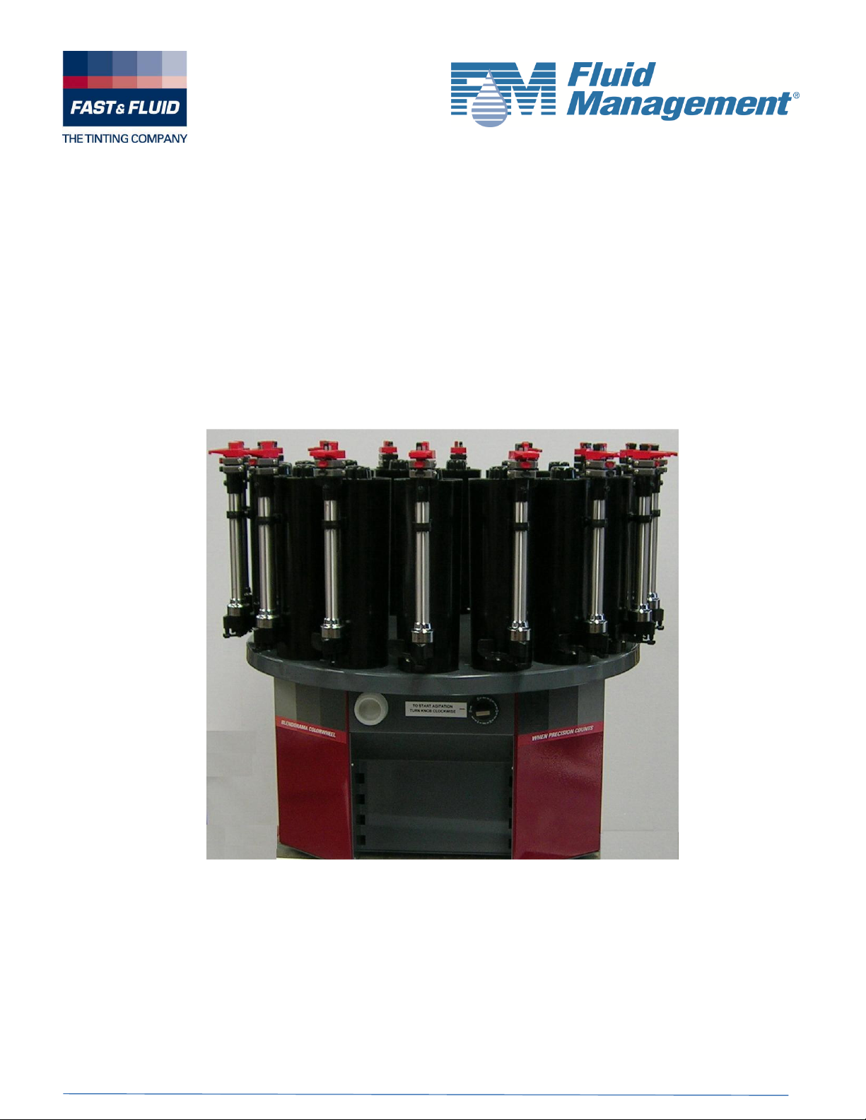
CW Bench Model INSTRUCTION MANUAL
22CW
ENGLISH
Page 2

PAGE NO. 2 of 27
I TABLE OF CONTENTS PAGE
II INTRODUCTION AND WARRANTY
A – Introduction 3
B – Standard terms and conditions of sale 3
III SAFETY INSTRUCTIONS
A – General safety instructions 7
B – Specific Warnings 7
IV
V
VI
INSTALLATION
A – Unpacking the dispenser 8
B – Installing the canisters –canister turntable
OPERATION
A – First time operation 11
B – General use of the dispenser 13
PREVENTITIVE MAINTENANCE
A – Do’s & Don’ts 16
B – Daily Maintenance 17
C – Weekly Maintenance 19
D – Periodic Maintenance 19
VII GENERAL MAINTENANCE
A - Replacement of Piston Seals - Model 22CW 21
B - Pump Calibration – Model 22CW 23
IIX TROUBLESHOOTING
A – Introduction 25
B – Problem solving 25
IX
SERVICE AGENTS
A – Service Agents 26
X TECHNICAL SPECIFICATIONS
A – Specifications 27
9
FAST & FLUID MANAGEMENT
CW - V1.2 – 10- 05- 2012 (36609) – rev, B
Page 3

PAGE NO. 3 of 27
II
Introduction, Conditions of Sale & Warranty
A - Introduction
By selecting a Fast & Fluid Management Color Dispenser you have opted for a product which is the result of
intensive research. Top-quality components, craftsmanship and a modern ergonomic design all serve to
guarantee a long service life and a high degree of user friendliness.
Blendorama Colorant Dispensers have been designed for long life and will withstand the normal wear expected
during use in plant or in store. However, each is a precision machined metering device and should be treated
accordingly
The basic unit of your dispensing system is represented as “Y” (except for metric and hybrid systems), and the
volume of this unit (approx. one fluid ounce) has been determined by the paint manufacturer.
The “Y” unit is further divided into (usually) 32, 48 or 64 sub-units. The basic unit of the metric dispenser is one
milliliter.
With the exception of Models 22/23XC, all feature a small bore inner pump to dispense small amounts of
colorant very accurately. The 1/64, 1/48 or milliliter units are divided further for this inner pump.
B - Standard Terms & Conditions of Sale
1. Application of Terms
These terms and conditions apply to every sale of a Blendorama Colorant Dispenser and Blendormix
mixers and each and every component part thereof ("the Product") by Fast & Fluid Management
Australia ("the Sellers) or any of its related companies to a Buyer and in the event that such Buyer
purchases the Product for resale, such resale shall be effected on the terms and conditions set out
herein, except for price, and such resale shall be deemed to be effected on such terms
in the name and on behalf of the parties to such resale transaction only, save for the Warranty
contained in paragraph 6 which is given in the name and on behalf of the Seller only
2. Passing of Risk - transfer of title in the product
Prices are quoted ex-works. The risk of loss or damage to the Product shall pass to the Buyer in the
case of a contract for supply of the Product immediately upon delivery either to the Buyer or a
nominated carrier for transportation to the Buyer or to a place or site nominated by the Buyer or at the
direction of the Buyer. Such delivery shall be deemed to be delivery to the Buyer and acceptance by
the Buyer of the Product whether or not the Buyer is present at the time of delivery to sign a receipt
for the Product. Notwithstanding the foregoing property in and title to the Product shall not pass to the
Buyer until payment in full for the Product has been received by the Seller
3. Delivery Time frame
Any date(s) given to the Buyer by the Seller for delivery shall be regarded as estimates only and
while the Seller shall use its best endeavors to meet such dates the Buyer agrees that no liability
shall attach to the Seller for any loss or damage, direct or consequential arising out of any delay in
delivery or for non-delivery from any cause whatsoever. If for any cause beyond the Seller's control,
the Seller is unable to deliver either within a reasonable time or at all, the contract shall be voidable at
the Seller's option with no right of either party to claim any damages against the other
4. Sole Terms
These terms and conditions constitute the entire agreement for sale of the Product between the
Seller and the Buyer and shall prevail over any differing terms and conditions incorporated or
purported to be incorporated into the sale of the Product by the Buyer or by the Seller or otherwise
alleged to have been agreed and shall only be varied modified or rescinded by written agreement of
the Seller.
and conditions
FAST & FLUID MANAGEMENT
CW - V1.2 – 10- 05- 2012 (36609) – rev, B
Page 4

PAGE NO. 4 of 27
B - Stand
ard Te
r
ms &
Conditi
ons
of Sale
(
con
t’)
5. Limitation of Liability
Subject to Paragraph 6 of these terms and conditions and in particular sub-paragraph 6.7 hereof the
seller shall neither be subject to nor incur, and the Buyer releases the Seller from any claim or liability
(including consequential loss or damage, loss or use or profit) by reason of delay, defective or faulty
components or materials or workmanship, negligence, or any act, matter or thing done admitted or
omitted by the Seller or by reason of the unsuitability of the Product for the Buyer's , purpose and the
Buyer acknowledges that it did not rely on the skill or judgment of the Seller in selecting and
ordering the Product for the purpose for which the same was required by the Buyers.
5.1 Product Return
Subject to paragraph 6 hereof or as otherwise agreed by the Seller the Buyer may not return the
Product or any part or parts thereof after delivery has been effected. Any claim or claims for return of
the Product or any Parts thereof must be made within 30 days of delivery of the Product to the Buyer.
6. Warranty
The Seller hereby warrants to the Buyer that the Product will be free from defects in materials and
workmanship in normal use, service and operation for a period of twelve (12) months from the date of
delivery effected by the Seller or one of its authorized Distributors to the Buyer.
The first year of the warranty period covers parts and labor. If any Paint Equipment fails during normal
operation, use and service during the first year of the warranty period due to a defect in material or
workmanship, Fluid Management will repair the defective Paint Equipment and replace any defective
parts at no charge to the Customer. The warranty repairs and defective parts replacement will be
carried out by Fluid Management or one of its Authorized Service Representatives. .
The above warranty and obligations are subject to the WARRANTY CONDITIONS, EXCLUSIONS
AND LIMITATIONS and the WARRANTY DISCLAIMERS AND LIABILITY LIMITATIONS set forth
below.
6.1 WARRANTY CLAIMS
Warranty claims must be asserted during the warranty period. While Paint Equipment is under
warranty, no repair or part replacement should be undertaken without first contacting Fluid
Management at 800-462-2466. To expedite the process, the model and serial numbers of the Paint
Equipment should be available at the time of the call.
6.2 WARRANTY CONDITIONS, EXCLUSIONS AND LIMITATIONS
Fluid Management shall have no liability or obligation under its warranty in connection with any
warranty claim asserted or any failure or malfunction occurring after the expiration of the warranty
period.
As a condition to any warranty repair or part replacement, Fluid Management shall have the right to first
inspect, test and evaluate the Paint Equipment and parts that are claimed to be defective.
Return of Paint Equipment and parts to Fluid Management requires a Return Goods Authorization
(RGA) from Fluid Management, and the RGA number must be included with any returned Paint
Equipment or part.
Customer shall be required to provide Fluid Management and its Authorized Service Representatives
with all information that any of them may request concerning the maintenance, operation, use, service,
failure or malfunction of Paint Equipment and parts that are claimed to be defective.
Fluid Management may use reconditioned parts for warranty repairs and parts replacement.
FAST & FLUID MANAGEMENT
CW - V1.2 – 10- 05- 2012 (36609) – rev, B
Page 5

PAGE NO. 5 of 27
B - Stand
ard Te
r
ms &
Conditi
ons
of Sale
(
con
t’)
Warranty repairs and part replacement do not extend the warranty period for Paint Equipment and
repaired Paint Equipment and replacement parts are warranted only for the remainder of the original
warranty period.
Any repair or replacement requested as a warranty repair or replacement that is not covered by
Fluid Management’s warranty will be billed to Customer as non-warranty repair or replacement on a
time and materials basis.
Fluid Management’s warranty transfers to the new owner with transfer of ownership Paint
Equipment. It is the responsibility of new owner to notify Fluid Management at 1-800-462-2466 of
the transfer of ownership of Paint Equipment. Transfer of ownership does not extend the warranty
period.
Fluid Management’s warranty does not cover, extend or apply to, or include:
• Computer or computer-related equipment such as laptops, monitors and printers and other third-party
equipment supplied with Paint Equipment (In the case of computer and computer-related equipment
such as laptops, monitors or printer, and other third-party equipment, any warranty is limited to a pass
through to Customer of any warranty received from the equipment manufacture, and is subject to
whatever terms, conditions and limitations are imposed by the equipment manufacturer)
• Third–party software (In the case of third-party software, any warranty is limited to a pass through to
Customer of any warranty received from the software provider and is subject to whatever terms,
conditions and limitations are imposed by the software provider)
• Normal wear and tear
• Any Paint Equipment or part that fails or malfunctions due to any computer or computer-related
equipment, other peripheral equipment, third-party software or software or equipment provided by
Customer or a third party
• Any Paint Equipment or part failure or malfunction that Fluid Management or one of its Authorized
Service Representatives determines to have been caused by or attributable to damage during or after
shipment, colorant in the wrong canister, colorant related issues (e.g. beads in colorant, etc.),
overfilling of canisters, improper operation or misuse, lack of daily maintenance, power surge, power
outage, fire, flood, water leakage, accident, acts of god, casualty, or other similar causes
• Any Paint Equipment or part that Fluid Management or one of its Authorized Service Representatives
determines was tampered with, disassembled, repaired, modified or altered by anyone other than
Fluid Management or one of its Authorized Service Representatives without the prior written
authorization of Fluid Management, used to mix or dispense material that the Paint Equipment was not
designed to mix or dispense or otherwise used for a purpose or under conditions that differ from those
for which the Paint Equipment was designed, or subjected to abnormal use or service, or has had its
serial number removed or altered.
• Field repair, removal, reinstallation or other similar tasks not performed by Fluid Management or one
of its Authorized Service Representatives
• Cabinets and structural frames
• Mistints or misfills
FAST & FLUID MANAGEMENT
CW - V1.2 – 10- 05- 2012 (36609) – rev, B
Page 6

PAGE NO. 6 of 27
B - Stand
ard Te
r
ms &
Conditi
ons
of Sale
(
con
t’)
6.3
WARRANTY DISCLAIMERS AND LIABILITY LIMITATIONS
THE ABOVE WARRANTY IS THE SOLE AND EXCLUSIVE WARRANTY MADE BY
FLUID MANAGEMENT WITH RESPECT TO EQUIPMENT, COMPONENTS OR PARTS
AND IS IN LIEU OF ALL OTHER WARRANTIES, EXPRESS OR IMPLIED, INCLUDING,
BUT NOT LIMITED TO, ALL WARRANTIES OF MERCHANTABILITY AND FITNESS FOR
A PARTICULAR PURPOSE, ALL OF WHICH OTHER WARRANTIES ARE EXPRESSLY
EXCLUDED.
THE OBLIGATIONS, RIGHTS AND REMEDIES SET FORTH ABOVE ARE THE SOLE
AND EXCLUSIVE OBLIGATIONS OF AND SOLE AND EXCLUSIVE RIGHTS AND
REMEDIES AGAINST FLUID MANAGEMENT WITH RESPECT TO ANY ALLEGED
DEFECT OR DEFICIENCY IN ANY EQUIPMENT, COMPONENTS OR PARTS.
UNDER NO CIRCUMSTANCES SHALL FLUID MANAGEMENT OR ANY OF ITS
AUTHORIZED SERVICE REPRESENTATIVES HAVE (I) ANY LIABILITY FOR ANY
CLAIM, LOSS, DAMAGE, INJURY, LIABILITY, OBLIGATION, COST OR EXPENSE THAT
DIRECTLY OR INDIRECTLY RELATES TO OR ARISES OUT OF THE PERFORMANCE
OF ANY SERVICES OR THE USE, FAILURE OR MALFUNCTION OF ANY EQUIPMENT,
COMPONENT OR PART OR (II) ANY LIABILITY FOR INDIRECT, SPECIAL, PUNITIVE
OR CONSEQUENTIAL DAMAGES, INCLUDING, BUT NOT LIMITED TO, LOSS OF
SALES, LOSS OF PROFITS, LOSS OF MATERIAL BEING DISPENSED, DOWN TIME,
LOSS OF PRODUCTION, LOSS OF CONTRACTS, OR DAMAGE TO REPUTATION OR
GOOD WILL, WHETHER OR NOT FLUID MANAGEMENT OR ANY OF ITS AUTHORIZED
SERVICE REPRESENTATIVES WAS AWARE OF OR ADVISED OF THE POSSIBILITY
OF SUCH DAMAGES.
IN ANY EVENT, FLUID MANAGEMENT’S TOTAL LIABILITY IN CONNECTION WITH
ANY INDIVIDUAL ITEM OF EQUIPMENT SHALL LIMITED TO THE NET PRICE PAID TO
FLUID MANAGEMENT FOR SUCH ITEM OF EQUIPMENT.
FAST & FLUID MANAGEMENT
CW - V1.2 – 10- 05- 2012 (36609) – rev, B
Page 7

PAGE NO. 7 of 27
III SAFETY
INSTRUCTI
O
NS
A - General safety instructions
Attention! Before installing the equipment, please read this instruction manual
carefully. This will increase your personal safety and prevent unnecessary
damage to the machine.
The manufacturer accepts no liability if the instructions below are not followed:
1. If a machine has been damaged (during transport, for example), do not attempt to set it in operation.
When in doubt, first contact either your supplier or the F&FM service department.
2. The equipment should be positioned and connected up in strict accordance with the installation
instructions.
3. All local safety regulations and ordinances should be observed.
4. The machine may be connected only to a 230/240V/50/60Hz or 110V/50/60HZ earthed wall socket
installed in accordance with the regulations.
5. Users should ensure that the machine is kept in good condition. Defective components should be
replaced.
6. In order to prevent physical injury, the doors should be closed and the paneling fitted during normal
use.
7. All service activities (other than routine maintenance and adjustments) may only be carried out by
qualified technicians. Ensure that the mains lead is always kept unplugged while repairs are being
carried out.
B - Specific warnings in this manual
Attention! MOVING PARTS CAN CAUSE INJURY. Always turn off power at
the wall socket before accessing moving parts.
FAST & FLUID MANAGEMENT
CW - V1.2 – 10- 05- 2012 (36609) – rev, B
Page 8
PAGE NO. 8 of 27
IV INSTAL
L
AT
I
ON
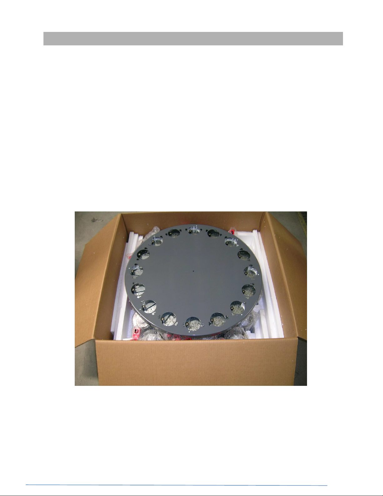
A - Unpacking the dispenser
The machine is packed in a box which will contain the following:
1 x Machine Base Assembly including turntable
Canisters (as ordered), each with a lid, attached pump and fixing screws
1 x Operation Manual
Power Supply cable.
A plastic bag or box containing:
1 x Allen Key for Pump Calibration (Note: Pumps preset in factory)
1 x No. 2 Phillips head screwdriver (for attaching canisters)
In case of floor stand models, a kit of parts is supplied in the same box to convert bench
model to floor model. (Assembly instruction manual will be provided with the kit)
If any of these parts are missing, contact your supplier or F&FM immediately.
FAST & FLUID MANAGEMENT
CW - V1.2 – 10- 05- 2012 (36609) – rev, B
Page 9
PAGE NO. 9 of 27
IV INSTAL
L
AT
I
ON
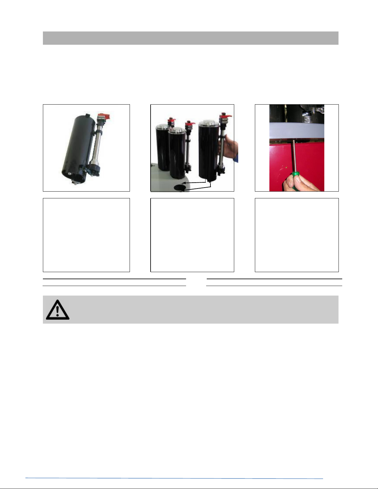
B - Installing the canisters
Please note that this procedure is used for all canister sizes, although only 1.75L (22X) canisters are shown
here. Other canister assemblies will vary in size and appearance, however the procedure remains the same.
> >
(1) Select a canister assembly. (2) Fit the canister screws
into the outer ring of keyhole
slots on the turntable. Push
firmly into position.
Attention!
correctly to ensure stability of the canisters on the turntable and correct
functioning of the stirring mechanism.
It is important that the canisters are assembled and installed
(3) Locate the 2 guide holes
directly below each canister
and fasten the screws
(already located in canister)
with a Philips (No. 2)
screwdriver.
(4) Check canister is firmly
secured.
(5) Repeat steps (2) to (4) for
all other outer ring canister
assemblies.
FAST & FLUID MANAGEMENT
CW - V1.2 – 10- 05- 2012 (36609) – rev, B
Page 10

PAGE NO. 10 of 27
IV INSTAL
L
AT
I
ON
C - Ensuring the machine will automatically stir the colorant.
The machine has a mechanical timer that will stir the colorant when turned
from the 0 minutes indication on the dial and continue stirring until the
timer expires. It is very important that the colorant is stirred to ensure
continuous smooth operation of the machine. If left unstirred for extended
periods, colorant can become thick and difficult to stir. This can
ultimately damage the machine. To ensure that the machine stirs the
colorants, please note the following.
LOCKED
UNLOCKED
(1) The machine will only start the stirring process
when you turn the timer clockwise to the
desired stirring period. The machine will stop
stirring when the timer expires.
The knob on the left is used to lock or unlock
the turntable.
>
(2) The power switch at the back of the machine
must be ON for the stirring process to start
when the timer is activated. (Canister refilling for
example).
FAST & FLUID MANAGEMENT
CW - V1.2 – 10- 05- 2012 (36609) – rev, B
Page 11

PAGE NO. 11 of 27
V OP
ERATIO
N
A - First time operation
Step 1 Preparing the dispenser
>
Ensure that the machine is
switched off at the wall socket
Stir each can of colorant
thoroughly with a flat
bottomed paddle or palette
knife to reincorporate any
settled pigment
Ensure that the machine is
adequately supported and
clear of obstructions
Remove the lids from all
canisters
Attention! Always wear eye protection when handling colorants
>
Pour the contents of each
colorant can into the correct
canister. Discard the colorant
can and replace the canister
lid
FAST & FLUID MANAGEMENT
CW - V1.2 – 10- 05- 2012 (36609) – rev, B
Page 12

PAGE NO. 12 of 27
V OP
ERATIO
N
Step 2 Purging the pumps
Set the gauge or gauges of
each pump to its halfway point
by operating the spring loaded
button then lifting the gauge by
its handle
Step 3 Purging the valve
>
>
Without operating the valve
lever lift the pump handle to
its maximum travel (this
draws the colorant into the
canister)
Discharge the colorant back
into the canister by
depressing the pump handle
fully. Repeat this process 30
times.
Lift the pump handle to its
maximum travel
Push the pump handle down
fully to dispense colorant into
the cup
> >
Place a can or paper cup
under the dispensing nozzle
> >
Release the valve lever Repeat this process until the
Hold the valve lever open by
pulling the spring loaded lever
forward its full travel
colorant emerges as an
unbroken stream
FAST & FLUID MANAGEMENT
CW - V1.2 – 10- 05- 2012 (36609) – rev, B
Page 13

PAGE NO. 13 of 27
IV OP
ERATIO
N
> >
V OP
ERATIO
N
Step 4 Check the effectiveness of the purge
Open the valve lever without
operating the pump. A small
drop of colorant will appear at
the nozzle
Release the valve lever
slowly and the drop will
withdraw into the nozzle
Attention! For dispensers fitted with electronic timers, it is important that the
machine be switch on at all times unless topping up canisters.
Attention! For manual agitation type dispensers, it is good practice to agitate
the colorant twice daily for four (4) minutes.
Repeat this process
times. If the drop of colorant
at the nozzle grows
appreciably with each opening
of the valve lever and/or it
drops from the nozzle into the
cup, then air is still in the
system and steps 2 & 3
should be
Repeat this process for all
canisters.
repeated
10
B - General use of the dispenser
Step 1 Select the color, base and can size
A
Identify the color you wish to supply either by name or number
B
Look up the tint formula and note the Tint Base required
C
Identify the quantity required (can size)
Step 2 Position the can
Picture not
available
Place the can on the
appropriate can shelf (if
supplied) and adjust the height
of the can shelf if necessary
FAST & FLUID MANAGEMENT
CW - V1.2 – 10- 05- 2012 (36609) – rev, B
Page 14

PAGE NO. 14 of 27
IV OP
ERATIO
N
V OP
ERATIO
N
Step 3 Bring canister to the correct position
>
Depress and hold the detent
lever to release the turntable.
You can lock the detent lever
in the release position by
pushing it sideways.
Rotate the turntable so that
the pump of the appropriate
canister is directly over the
can. If the detent lever is
released it will lock the
canister into the correct
position. You may need to
move the turntable slightly
from side to side to allow the
locking pin to locate the
locking hole.
When rotating the turntable, DO NOT use the canisters or pumps as handles.
Use the edge of the turntable.
Step 4 Set the Gauges
According to the setting
required, operate the spring
loaded button to release the
gauge. The red knob is for the
red gauge and the black knob
is for the black gauge
CW - V1.2 – 10- 05- 2012 (36609) – rev, B
> >
With the appropriate button
operated, lift the gauge to the
reading required.
FAST & FLUID MANAGEMENT
The correct gauge setting is
shown when the figure
selected is fully exposed
above the RED handle and
the gauge release button
clicks firmly into place.
Page 15

PAGE NO. 15 of 27
IV OP
ERATIO
N
V OP
ERATIO
N
Step 5 Charge the pump
With the gauges correctly set,
slowly and gently lift the red
pump handle until both red and
black handles are against the
appropriate gauge knobs
If the colorant level is too low, air can be sucked into the pump. If this occurs,
return the handle to the zero position, add sufficient colorant, and purge the
pumps and valve (see chapter IV, step 2 & 3)
Step 6 Discharge the pump
>
Continue to hold this for a few
seconds to ensure the pump
is correctly filled with colorant.
While still holding the pump
handle in the raised position,
pull the spring-loaded valve
lever (at the base of the pump)
forward its full travel
CW - V1.2 – 10- 05- 2012 (36609) – rev, B
> >
Holding the valve lever fully
forward, press the red handle
down with a smooth and
steady stroke until the red
handle is fully depressed.
Repeat the charging and
discharging process for each
colorant specified in the formula
FAST & FLUID MANAGEMENT
container of the same color, leave the gauges
set at the required reading and simply
recharge and discharge each pump in turn in
the order nominated by the tint formula
Ensure that both the red and
black handles are fully
depressed against the end
cap. All the colorant has now
be discharged and the valve
lever can be released
If you have to tint more than one
Page 16

PAGE NO. 16 of 27
VI PRE
V
ENTI
TIVE
MAINTENA
N
CE
DO
DON’T
DON’T
DON’T
DON’T
A - Do’s & Don’ts
DO
Keep the machine clean and display advertising promoting good housekeeping.
Keep this operation manual, Allen key, valve sleeve wrench and spare parts in a
convenient place to assist in regular maintenance
Use the piston or valve assembly of each pump as a handle to rotate the
turntable. Instead, use the canister or edge of the turntable.
Attempt to replace the valve plate – if this is faulty, the whole valve assembly must
be replaced
Make any adjustments to the stirring timer. This unit has been factory set and
should only be adjusted by authorized personnel.
Don’t use flammable cleaning fluids to clean or lubricate the machine unless it is a
explosion proof model.
FAST & FLUID MANAGEMENT
CW - V1.2 – 10- 05- 2012 (36609) – rev, B
Page 17

PAGE NO. 17 of 27
VI PRE
V
ENTI
TIVE
MAINTENA
N
CE
B - Daily maintenance
Wipe down stand, canisters
and pumps with a moistened
cloth
Refit the nozzle and dispense
a small amount of colorant
Clean the machine, refill canisters and check for blockages
>
Check nozzle outlets for dried
colorants.
>
If dried colorant is found to be
blocking the nozzle, open the
valve to remove and replace
the nozzle. Ensure the o-ring
is retained. Clean the nozzle
using warm soapy water
FAST & FLUID MANAGEMENT
CW - V1.2 – 10- 05- 2012 (36609) – rev, B
Page 18

PAGE NO. 18 of 27
VI PRE
V
ENTI
TIVE
MAINTENA
N
CE
If the dispenser is not used on a regular daily basis, the following procedure should
be carried out.
Check the level of colorant and
top up if required
Purge the pumps (see chapter
IV, step 2 & 3) however only
operate the pump 5 times
> >
Ensure that power is
connected to the dispenser
and turned on so that
stirring occurs
>
Check the valve levers and
nozzle wiper arms for
possible damage.
Open and close each pump
valve 5 times
FAST & FLUID MANAGEMENT
CW - V1.2 – 10- 05- 2012 (36609) – rev, B
Page 19

PAGE NO. 19 of 27
V PRE
V
ENTIT
I
VE
MAINTENA
N
CE
VI PRE
V
ENTIT
I
VE
MAINTENA
N
CE
C - Weekly maintenance
> >
Examine the machine for loose
canisters and loose cylinder
caps. Tighten if necessary
Examine gauges for
damaged graduated scales or
worn holes and replace if
necessary
D - Periodic maintenance
This maintenance should be carried out every 3 to 6 months depending upon use.
>
Inspect the function of the
valve and the canister for leaks
Ensure that the machine is
disconnected from the power
source
Raise the pump handle to its
maximum extension and
examine the pump shafts for
signs of colorant. This
indicates that the piston seal
will need replacement (see
Chapter VI - E,F,G)
>
Remove canister from
turntable and drain colorant
into a clean container
FAST & FLUID MANAGEMENT
CW - V1.2 – 10- 05- 2012 (36609) – rev, B
Page 20

PAGE NO. 20 of 27
V PRE
V
ENTIT
I
VE
MAINTENA
N
CE
VI PRE
V
ENTIT
I
VE
MAINTENA
N
CE
REMOVE SPLIT PIN
Remove stirrer paddle from
canister and wash the canister,
lid and stirrer paddle clean
Reassemble and refit canister
to turntable
Attention! MOVING PARTS CAN CAUSE INJURY. Always turn off power
before accessing moving parts.
(8) Using a sharp knife or blade
cut any excess metalcal off the
end of the gauge that may
overlap the black plastic handle.
> >
If required, tighten or replace valve
insert sleeve (with the wrench
supplied). Take care not to over
tighten or sleeve with crack.
>
Return colorant to dispenser
and prepare the pump for
operation (see chapter IV - A)
(9) Refit the gauge to the
plunger. Repeat steps (4)
through (9) for the inner
(red) gauge metalcal.
Replace “O” ring seal – item 9
FAST & FLUID MANAGEMENT
CW - V1.2 – 10- 05- 2012 (36609) – rev, B
Page 21

PAGE NO. 21 of 27
VI GENE
R
AL
M
AINT
E
NANCE
>
VII
GENERAL MAINTENA
N
CE
A - Replacement of Piston Seals
Models 22 CW
Step 1 Replacement of the inner piston
>
(1) Loosen both grubscrews in the cylinder of the
end cap (use Allen key provided) and remove the
plunger assembly from the cylinder. Remove the
gauges from the plunger assembly, then withdraw
the inner plunger assembly from the hollow outer
plunger shaft. Clean all colourant from both plunger
assemblies.
Step 2 Replacement of the outer piston
PLEASE NOTE
WASHER USED IN
AFTER SEPT 2004
THE EXTRA
PLUNGERS
PRODUCED
(2) Using two pairs of pliers, grip the inner end of
the piston (A) with one and the piston shaft with
the other. Unscrew the piston (using a little heat if
difficult) and discard.
(3) Apply Loctite 262 to the internal thread of the
piston shaft, then screw the new piston assembly
in fully. Slide sleeve up onto the shaft, tighten the
piston with pliers and replace the sleeve over the
piston.
>
(1) Using two spanners,
carefully undo the lower piston
nut. Discard the piston but
retain the nut.
(2) Remove the new piston
from retainer and fit to the
shaft curved end face up (see
picture). Replace the front nut
using a small drop of Loctite
262 on thread. Tighten the
nut only until the piston can
no longer be rotated by hand.
A
B
A
(3) Holding the end cap (A) in
one hand, pull the outer pump
handle (B) until the piston is
fully withdrawn inside the end
cap.
CW - V1.2 – 10- 05- 2012 (36609) – rev, B
FAST & FLUID MANAGEMENT
Page 22

PAGE NO. 22 of 27
VI GENE
R
AL
M
AINT
E
NANCE
VII
GENERAL MAINTENA
N
CE
Step 3 Returning plungers into cylinders
(1) After lightly oiling the top
inside edge of the cylinder,
position the plunger assembly
on the cylinder with one hand.
With the palm of the other
hand, firmly push the plunger
down fully.
> >
(2) Tighten end cap assembly
onto cylinder assembly using
Allen key.
(3) Remove the sleeve from
the inner piston and discard.
Lightly oil the inside edge of
the hollow outer piston shaft
and then gently ease the
piston inside. Refit the
gauges.
CW - V1.2 – 10- 05- 2012 (36609) – rev, B
FAST & FLUID MANAGEMENT
Page 23

PAGE NO. 23 of 27
VI GENE
R
AL
M
AINT
E
NANCE
VII
GENERAL MAINTENA
N
CE
B - Pump Calibration
Models 22 CW
Recalibration of the pump is necessary if the original gauge has been replaced by another (for any reason) or if
the gauge scale detail (metalcal) is to be replaced. When recalibrating the pump, please leave the
pump/canister fixed in place on the machine.
Tools required:
• 1 x Allen (hex) key 3/32” A/F (originally supplied with the machine)
(1) To calibrate the outer plunger, remove the
inner (red) gauge and inner (red) plunger and set
the outer (black) gauge to the zero position.
ALLEN (HEX) KEY
MOVEMENT
CHECK
BLACK
GAUGE SET
TO ZERO
(3) Carefully wind one grubscrew down until only
slight movement is felt between the outer pump
handle and the gauge knob. Then wind the other
grubscrew down until no free movement can be
felt, being careful not to over-adjust.
ALLEN (HEX)
KEY
>
(2) Using the Allen key, undo both calibration
grubscrews until free movement can be felt
between the outer (black) plunger handle and the
outer (black) gauge knob.
>
(4) To calibrate the inner (red) plunger, refit the
inner (red) gauge and plunger removed in step
(1). Set the inner (red) gauge to zero.
CW - V1.2 – 10- 05- 2012 (36609) – rev, B
FAST & FLUID MANAGEMENT
Page 24

PAGE NO. 24 of 27
VI GENE
R
AL
M
AINT
E
NANCE
RED GAUGE
ALLEN
(HEX)
KEY
(5) Using the Allen key, undo the calibration
grubscrew in the red pump handle until free
movement can be felt in the handle. Carefully wind
the grubscrew back down until no free movement
can be felt between the red pump handle and the
red gauge knob. Be careful not to over-adjust.
SET TO ZERO
CHECK
MOVEMENT
>
(6) The pump is now calibrated.
FAST & FLUID MANAGEMENT
CW - V1.2 – 10- 05- 2012 (36609) – rev, B
Page 25

PAGE NO. 25 of 27
IIX
TR
O
UBL
E
SHO
O
TING
Colorant
intermittently spurts from the
> A
ir b
ubb
les in the colo
rant >
Opera
te the pump sev
eral times without
A drop of colorant falls from the nozzle when
> A
ir is trappe
d in the cyli
nder assembly >
Opera
te the pump sev
eral times without
The end cap twists or lifts dur
ing operation > End-cap
grub-screws are loose > Lightly tighten the 2 grub-screws in the
Canister is loose on turntable > Loose fixing screws
Colorant
appear
s on the piston shaft, piston
> Worn seals > Replace seals – refer to
pages 33 to 36
Colorant
does not dispense easily >
Nozzle blocked > Remove nozzle and clean in warm
Colorant st
ill does not dispense eas
ily > H
igh viscosity of colo
rant > Increase the size of the nozzle
Colorant has hardene
d in the canister and
> > Canister and pump s
hould be removed,
Agitation is not occurring > No power to the dispenser
A - Introduction
Before calling your machine supplier or Service Department, please check whether you can solve the problem
yourself. If you cannot, then call the Service Department for advice. Have the model number and serial number
at hand (these can be found on the sticker attached to service door at the side of the machine).
Attention! MOVING PARTS CAN CAUSE INJURY. Always turn off power
before accessing moving parts.
B - Problem solving
Symptom Cause Action
nozzle during discharge
the valve is opened even when the pump is
not operated
and/or gauges
piston assembly
opening the valve to drive the air back
into the canister. Then allow the
colorant to sit for several minutes to
allow the bubbles to escape.
opening the valve to drive the air back
into the canister. Then allow the
colorant to sit for several minutes to
allow the bubbles to escape.
end-cap (for 53 XB/XD/XE tighten the
end-cap sleeve) until the end cap can no
longer be twisted by hand.
> Tighten fixing screws with a philipps
head screwdriver
soapy water
emptied, stripped and cleaned
thoroughly. Replenish only with new
colorant
> Check that the unit is connected and
that there is power to the outlet
FAST & FLUID MANAGEMENT
CW - V1.2 – 10- 05- 2012 (36609) – rev, B
Page 26

PAGE NO. 26 of 27
IX SERVICE and
S
UPPORT
A - Service and Support Information
For all service and repairs on Fast & Fluid Management products
(including all warranty repairs), call your local Fast & Fluid
Management Agent or Supplier.
Within Australia you can call the Fast & Fluid Management Service:
Free toll line: 1800 648584
Fax Number: 02 42717306
Or email on: FAU_Service@idexcorp.com
Within the United States, Canada & Latin America, you can call Fluid
Management Customer Service:
Free toll line: 1-800-462-2466
Fax Number: 1-847-537-3221
Or email: info.fluid@idexcorp.com
International Customers:
Phone Number: +61 2 4223 7460
Fax Number: +61 2 4271 7306
Or email on: FAU_Support@idexcorp.com
For more information, please visit our website www.fast-fluid.com or
www.fluidman.com.
Please make sure that you have the model number and serial number
to hand. They can be found on the nameplate on the machine.
FAST & FLUID MANAGEMENT
CW - V1.2 – 10- 05- 2012 (36609) – rev, B
Page 27

PAGE NO. 27 of 27
X SPECIF
ICATIONS
A - Specifications
Number of canisters
Canister sizes
canister/stirrer material)
Valves
Pump type
Pump size Inner
Pump size Outer
Min. dispensing
Stirring timer
Moveable upper can shelf
Power supply
Up to 16
1.75L Single canisters
molded 100% Acetal
molded 100% Acetal
piston pump
¼ ounce (22CW)
2 ounce (22CW)
1/384 fl.oz
Adjustable clockworks timer
Optional on floor model
A kit of parts is supplied as an optional extra to convert
Bench model to floor model. (assembly instruction manual
provided separately)
110V 50Hz/60Hz
230/240V 50Hz/60Hz
Specifications subject to change without prior notice.
FAST & FLUID MANAGEMENT
CW - V1.2 – 10- 05- 2012 (36609) – rev, B
 Loading...