

Page 1
Experience In Motion
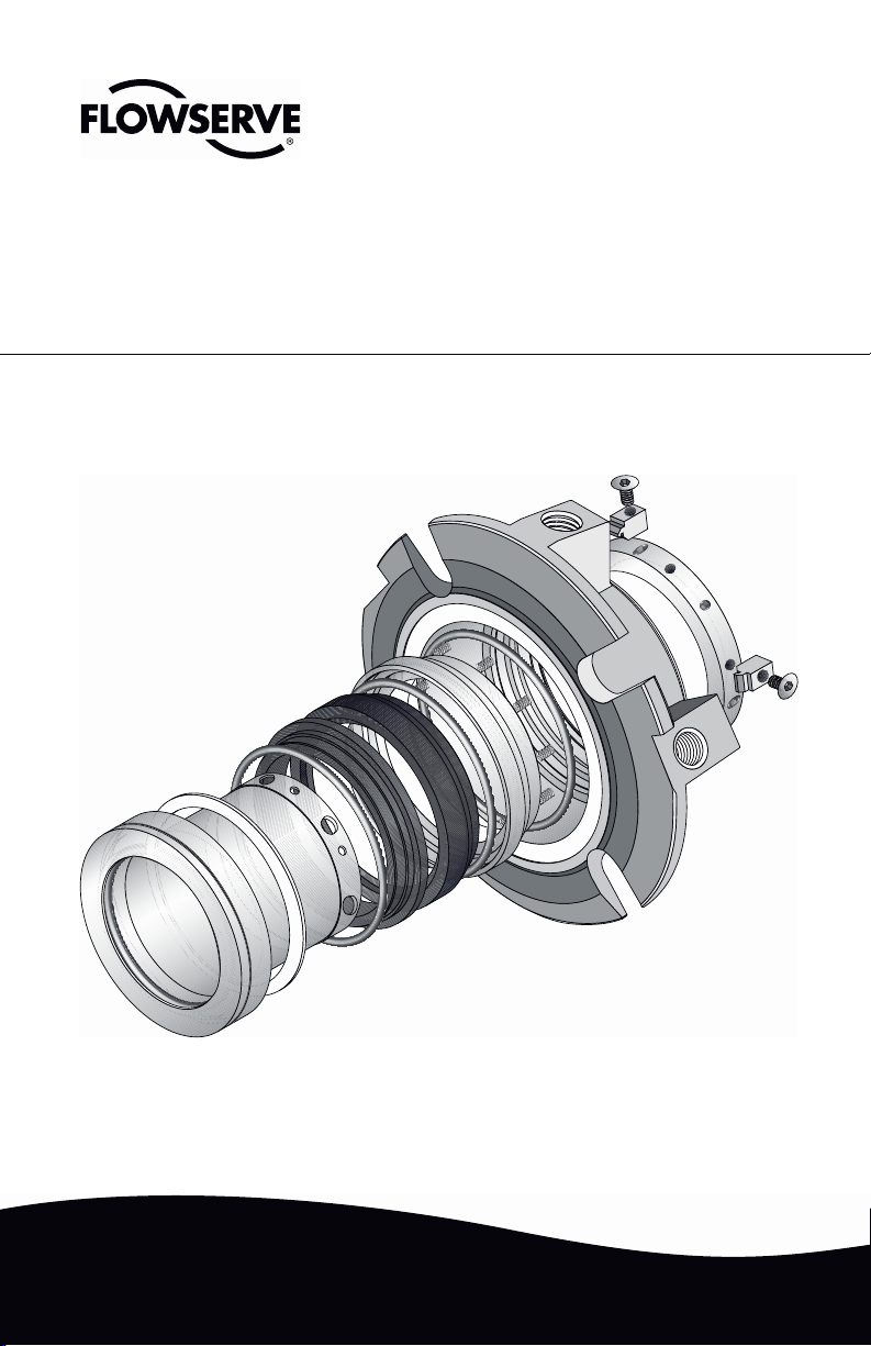
ISC
ISC1PX
Single Pusher Seal
Repair
Instructions
Page 2
These instructions are written for trained, experienced technicians familiar with the basic
19 183 1
100
24 40
57.1
103
18 76 2 15 14
13.1
13 16
58
5711
principles and tools involved in the installation, care and service of mechanical seals and
seal support systems. A complete reading of these instructions by personnel in contact
with the equipment is essential to safety. Incorrect installation, operation or maintenance
can result in personal injury or death to personnel and damage to the equipment.
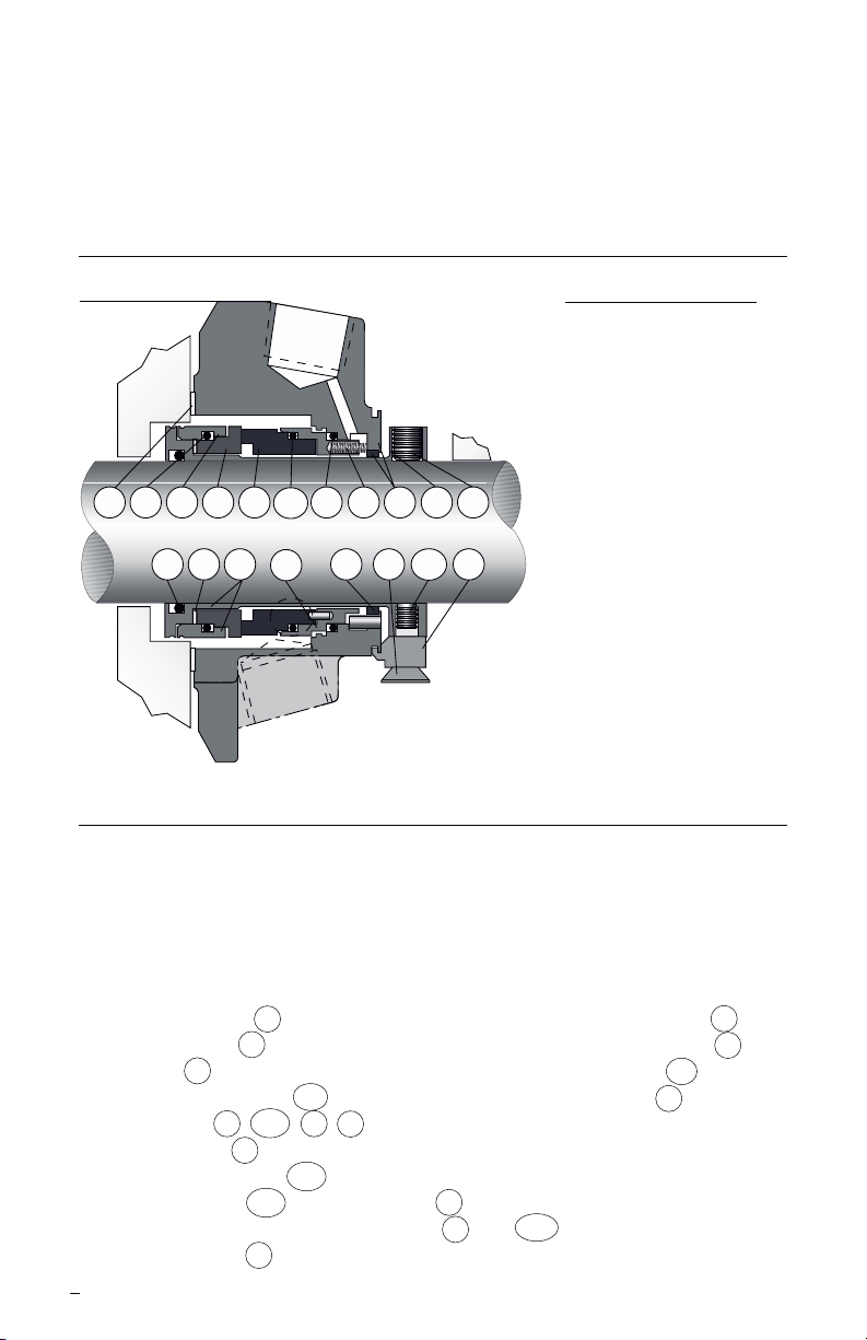
1 Nomenclature
Figure 1
Note: Primary seal O-rings (13, 13.1,76) are
all the same size and cross section.
Table 1
14 Stationary Face
15 Rotating Face
16 Springs
100 Stator Face Support
13 Dynamic (seat gasket)
13.1 Stator (seat gasket)
76 Rotating Face Gasket
18 Gland Gasket
11 Gland Assembly
24 Gland Bushing
103 Setting Device
40 Cap Screw
1 Sleeve Assembly
2 Seal Drive
183 Vibration Dampener
58 Drive Collar
57 Cup Point Set Screw
57.1 Quarter Dog Set Screw
19 Sleeve Gasket
2 Disassembly
When disassembling seal, inspect for conditions which may have caused the
need for the seal to be removed from service. If seal was removed due to
premature failure, determine what conditions caused that failure and correct any
problems prior to returning the repaired seal to service. For assistance with seal
failure analysis, please contact your Flowserve representative.
Seal Parts that are always replaced
• Stationary Face 14
• Rotating Face 15
• Springs 16
• Stator Face Support 100
• All O-rings 13 , 13.1 , 76 , 19
• Gland gasket 18
• Vibration dampener 183
• Setting Devices 103 and cap screws 40
• Cup point and quarter dog set screws 57 and 57.1
• Gland Bushing 24
2
Reconditionable Seal Parts
• Gland assembly 11
• Sleeve assembly 1
• Drive collar 58
• Seal Drive 2
Page 3
3 Inspection and Reconditioning
3.1 There are certain critical areas of each part where special attention should
be paid to the condition. If any of the areas listed in 3.2, 3.3 or 3.4 show
signs of wear, corrosion, or other defects that cannot be removed without
affecting the dimensional size of the surfaces by more than 0.001 to 0.002",
then the respective part should be replaced. If grit blasting is performed, it
may be necessary to polish the O-ring surfaces to achieve the required
surface nish (see 3.2A and 3.3A for the required surface nish). If any
parts require machining to correct damage, please contact your Flowserve
representative for dimensional requirements, or for any other questions
regarding repair.
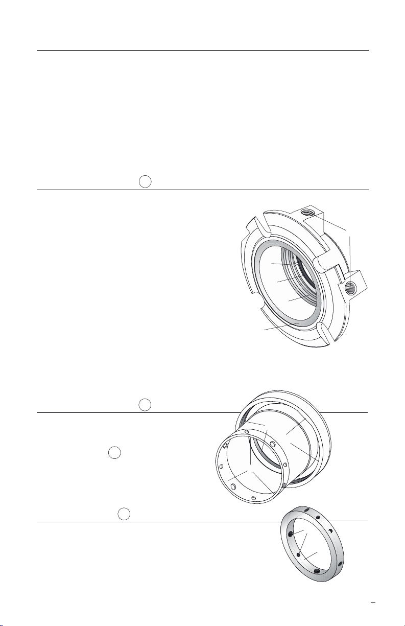
3.2 Gland Assembly 11 (Figure 2)
A Dynamic O-ring surface - Inspect for wear,
fretting, nicks, scratches, or corrosion.
Required surface nish: 32 RMS
B Gasket surface - Remove the old gasket
and clean the gasket surface. Inspect for
nicks, scratches, or corrosion.
E
C Pipe taps and other threaded holes -
Inspect for damaged threads or corrosion.
Taps must be clean and free of debris and
corrosion. Re-tap as necessary.
D
A
D Bushing - Inspect for wear, breakage, or
loosened bond with gland. Replace using
B
Loctite®1 7471 Primer T and Loctite RCTM/
640 or equivalent to adhere the bushing if any of these conditions exist. A
ten minute cure at 400°F (204°C) is required to achieve full bond strength.
E Anti-rotation pins - Inspect for wear or corrosion. If worn or corroded,
contact your Flowserve representative.
3.3 Sleeve Assembly 1 (Figure 3)
A O-ring surfaces - Inspect for wear,
nicks, scratches, or corrosion.
Required surface nish: 63 RMS.
A
B
B Seal Drive 2 - Inspect for wear or
corrosion, especially at drive at
surfaces on ID of drive ring.
C
C Drive end roundness -
No greater than 0.001" TIR
3.4 Drive Collar 58 (Figure 4)
A Threaded holes - Inspect for thread damage and
A
re-tap as necessary.
B ID bore roundness - no greater than 0.002" TIR
C Set screws - Replace cup point and dog point set
screws with those included with the repair kit. Make
sure the same threaded holes are used with the same type set screws.
1 Registered Trademark of Loctite Corporation
Figure 2
C
Figure 3
Figure 4
B
3
Page 4

4 Seal Assembly Instructions
4.1 Tools Required
• 3/32", 1/8" hex key wrenches (Sizes < 2.625"); 1/8", 3/16" hex key
wrenches (Sizes 2.625" and larger)
• Silicone grease (included in repair kit)
• Ethyl alcohol and clean, lint free towel for cleaning seal faces
4.2 As part of the assembly of the seal, there are several blind ts of pins and
drive ats. It may be helpful to mark the locations of the pins or drive ats
with a felt tip marker, or to align the feature with another visible feature on
the seal to assist with assembly. All seal faces should be cleaned with
alcohol prior to placing the faces together at each respective step in the
assembly process.
4.3 Arrange O-rings by dia metrical size. There are two
sizes: three of the largest
size (O-rings 13 , 13.1 , and
76 ), and one of the smallest
size (O-ring 19 ). Prior to
installing each O-ring at its
respective step, lightly
lubricate with silicone grease
and stretch slightly.
4.4 Place the sleeve assembly
1 on a at surface with the
drive collar end facing up.
Install the vibration dampener
183 into sleeve end housing.
Place the rotating face O-ring
76 in sleeve O-ring groove
behind surface with drive ats
in sleeve. Install sleeve
gasket O-ring in groove in ID
of sleeve. (Figure 5)
4.5 Align the two ats on the
rotating face 15 with the
two ats on the inside of
the seal drive 2 and press
the rotating face into place
using nger pressure only.
(Figure 6)
Sleeve
Gasket
O-ring
19
Rotating Face
Gasket 76
Rotating
Face
15
Figure 5
Vibration
Dampner
183
Figure 6
Drive
Flats
4
Seal
Drive
2
Page 5

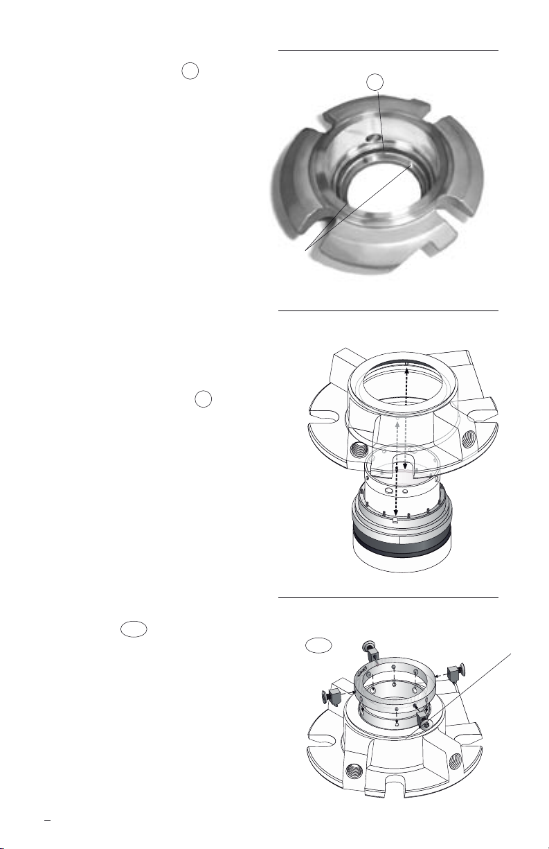
Figure 7
Figure 8
Align
Drive Pin
with Slot
Seat Gasket
O-ring 13.1
Stationary
Face
14
Face
Support
Spring
Locations
4.6 Place the seat gasket O-ring
13.1 on the O-ring surface
of the stationary face 14 ,
which is the smallest outside
diameter. Place the stationary
face with the sealing face
down on a clean, at surface.
(Figure 7)
4.7 Align the stationary face drive
pins in stator face support 100
with the drive slots in the
stationary face and press the
stationary face support in
place using nger pressure
only. (Figure 8)
4.8 Install the springs 16 in holes
of stator face support.
4.9 Place the stationary face
and stationary face support
assembly face down onto the
sleeve/rotating face assembly.
(Figure 9)
Stationary
Face
14
Stationary Face
and Stationary Face
Support Assembly
Sleeve and Rotating
Face Assembly
Figure 9
5
Page 6
4.10 Place the outboard dynamic
seat gasket O-ring 13 in the
dynamic O-ring surface of the
gland assembly. (Figure 10)
4.11 Align the gland assembly
drive pins (Figure 10) with
the slots in the outside
diameter of the stationary
face support. Firmly and
evenly press the gland onto
the stationary face support.
(Figure 11)
Caution: do not rotate the gland
to align pins while
pressing down. This
could damage the
springs. Once the gland
is in the proper position
do not rotate it until the
seal is fully assembled
to ensure that the pins
remain engaged.
4.12 Place the drive collar 58
onto the end of the sleeve
with the “Flowserve” logo
facing up. (Figure 12) Align
the quarter dog set screws
with the smaller holes in the
end of the sleeve. On smaller
seal sizes, one of the quarter
dog set screws will be offset
by 15 degrees. Align this
quarter dog set screw with
the corresponding offset hole
in the end of the sleeve. Do
not tighten any set screws at
this time. Install the setting
devices 103 and at head
cap screws into the drive
collar while engaged with the
gland. Be sure to keep the
drive collar aligned and be
careful not to rotate the
gland.
Gland
Assembly
Drive Pins
Setting
Devices
Seat Gasket O-ring
13
103
Figure 10
Figure 11
Figure 12
6
Page 7

4.13 Compress the drive collar to be
even with the end of the sleeve
assembly. This will also compress
the gland. While holding the
collar in compression, tighten
the quarter dog set screws into
the holes in the sleeve until
snug. (Figure 13) Be careful
not to distort the sleeve by
over tightening the quarter
dog set screws.
Note: if the drive collar cannot be
compressed to be even with
the end of the sleeve, the gland
drive pins may not be aligned.
If this is the case, do not
attempt to rotate the gland to
align the pins. The gland should
be disassembled and re-aligned
prior to proceeding further.
4.14 Install the sleeve gasket O-ring 19
into the inside diameter groove of
the sleeve assembly. (Figure 14)
4.15 Apply an even coat of 3M®2
Super 77 spray adhesive,
free of bubbles and nodules,
to the gland gasket 18 . Adhere
the gasket to the gland gasket
surface. (Figure 14)
5 Static Testing
Sleeve
Gasket
O-ring
19
Gland
Gasket
Figure 13
Figure 14
18
5.1 Flowserve manufacturing typically air tests the ISC at 25 psig. A pressure
drop of less than one pound at 25 psig is acceptable. To static test the seal,
bolt it to a single seal test barrel or to the equipment. Secure the cup point
set screws to the stub shaft or equipment shaft to prevent deformation
of the setting devices due to axial loads. The seal may be pressurized
through either of the tangential ush ports. If the seal does not pass the
static pressure test, disassemble the seal and inspect for O-ring damage, as
this is the most common cause of static test failure.
6 Installation
6.1 Refer to the ISC Installation Instructions, FIS120, for proper seal installation.
7
Page 8

TO REORDER REFER TO
flowserve.com
USA and Canada
Kalamazoo, Michigan USA
Telephone: 1 269 381 2650
Telefax: 1 269 382 8726
Europe, Middle East, Africa
Essen, Germany
Telephone: 49 201 31937-0
Telefax: 49 201 2200-561
Asia Pacific
Singapore
Telephone: 65 6544 6800
Telefax: 65 6214 0541
Latin America
Mexico City
Telephone: 52 55 5567 7170
Telefax: 52 55 5567 4224
B/M #
F.O.
FIS136eng 08/07 Printed in USA
To nd your local Flowserve representative
and nd out more about Flowserve Corporation,
visit www.owserve.com
Flowserve Corporation has established industry leadership in the design and manufacture of its products. When
properly selected, this Flowserve product is designed to perform its intended function safely during its useful life.
However, the purchaser or user of Flowserve products should be aware that Flowserve products might be used
in numerous applications under a wide variety of industrial service conditions. Although Flowserve can provide
general guidelines, it cannot provide specic data and warnings for all possible applications. The purchaser/user
must therefore assume the ultimate responsibility for the proper sizing and selection, installation, operation, and
maintenance of Flowserve products. The purchaser/user should read and understand the Installation Instructions
included with the product, and train its employees and contractors in the safe use of Flowserve products in connection
with the specic application.
While the information and specications contained in this literature are believed to be accurate, they are supplied for
informative purposes only and should not be considered certied or as a guarantee of satisfactory results by reliance
thereon. Nothing contained herein is to be construed as a warranty or guarantee, express or implied, regarding any
matter with respect to this product. Because Flowserve is continually improving and upgrading its product design,
the specications, dimensions and information contained herein are subject to change without notice. Should any
question arise concerning these provisions, the purchaser/user should contact Flowserve Corporation at any one of
its worldwide operations or ofces.
© Copyright 2007 Flowserve Corporation
 Loading...