

Page 1
CBR Series
Experience In Motion
Single Inside Bellows Seal
Installation
Instructions
Page 2
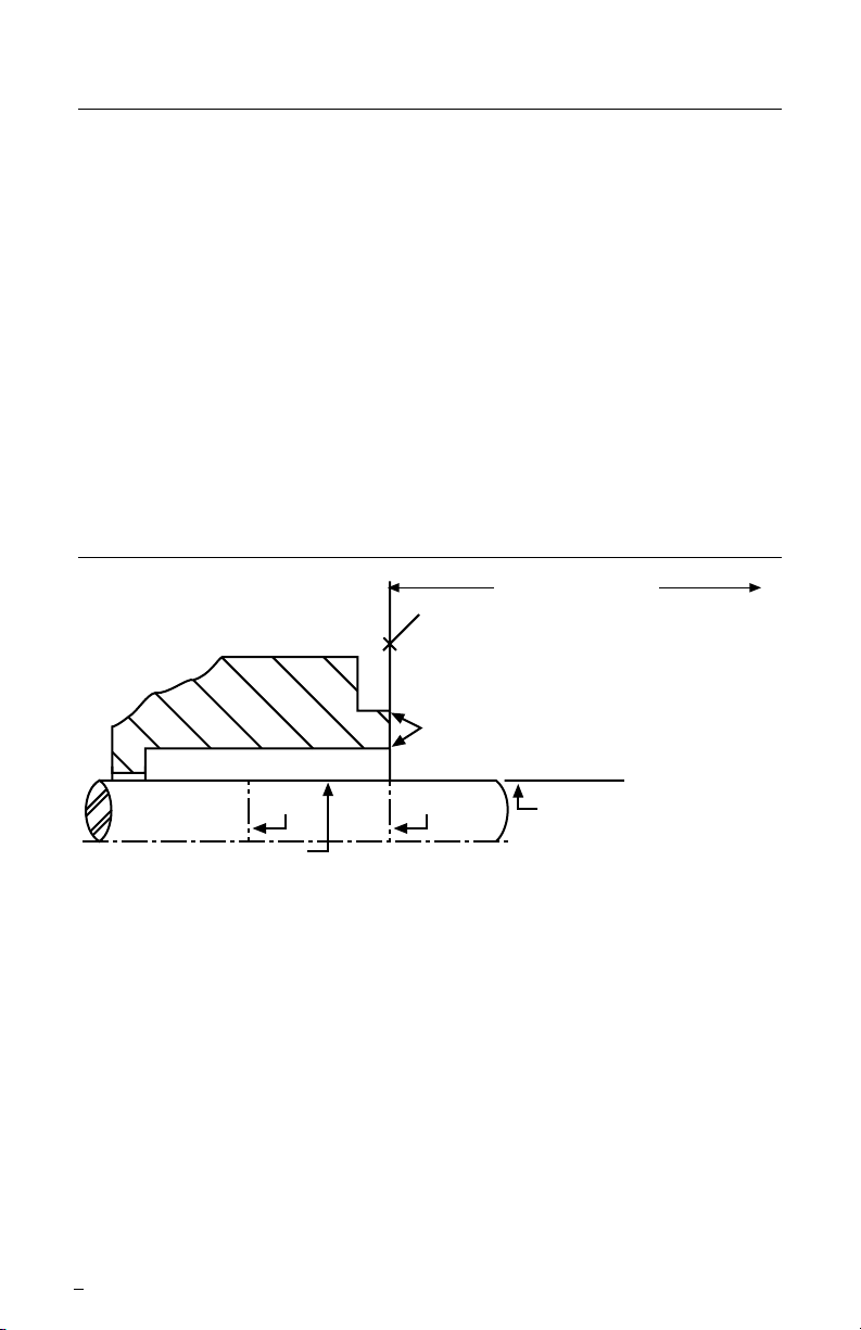
1 Equipment Check
To first obstruction
Face of seal housing to be square to the axis
of the shaft to within 0.0005 inches per inch of
seal chamber bore (0.013 mm) FIM and ha
ve a
√63 µinch (1.6 µm) R finish or better
a
Gland pilot can be at either of these
register locations. concentric to within
0.005 inch (0.13 mm) FIM of shaft or sleeve OD
Sleeve or shaft finish to be
32 µinch (0.8 µm) R or better
a
a
Scribe
Mark A
Shaft or sleeve OD
+0.000 inch (+0.000 mm)
-0.002 inch (-0.050 mm) ANSI
+0.000 inch (+0.000 mm) API 610
-0.001 inch (-0.025 mm) DIN/ISO
• Bearings must be in good condition
• Maximum lateral or axial movement of shaft (end play) = 0.010 inch (0.25 mm) FIM
• Maximum shaft runout at face of seal housing = 0.002 inch (0.05 mm) FIM
• Maximum dynamic shaft deflection at seal housing = 0.002 inch (0.05 mm) FIM
Scribe
Mark B
Seal housing bore to have √125 µinch
(3.2 µm) R finish or better
1.1 Follow plant safety regulations prior to equipment disassembly:
• lock out motor and valves.
• wear designated personal safety equipment.
• relieve any pressure in system.
• consult plant MSDS les for hazardous material regulations.
1.2 Disassemble equipment to allow access to seal installation area.
1.3 Remove all burrs and sharp edges from the shaft or sleeve including sharp edges of keyways and threads. Replace worn shaft or
sleeve. Make sure the seal housing bore and face are clean and
free of burrs.
1.4 Check requirements for shaft, sleeve and seal housing.
See Figure 1.
Seal Chamber Requirements Figure 1
1.5 Check assembly drawing included with the seal for specic
seal design, materials of construction, dimensions, and piping
connections.
1.6 Check shaft or sleeve OD, box bore, box depth, and distance
to rst obstruction to ensure that they are dimensionally the same
as shown on the seal assembly drawing.
2
Page 3

1.7 Check gland pilot and bolt holes to ensure they are adaptable
to the equipment and are the same as shown on the assembly
drawing.
1.8 Handle all seal parts with care, they are manufactured to precise
tolerances. The seal faces; Seal Ring and Insert, are of special
importance. These two sealing faces are lapped at to within
three light bands (34.8 millionths of an inch). Keep the seal faces
perfectly clean at all times.
2 Installation
The basic CBR design is shown in Figure 2. Variations may include
rotating face gasket, seat gasket, and environmental control features.
See the Flowserve assembly drawing included with each complete seal
for details. Additional recommendations for vetical pumps are shown in
section 3.
2.1 Scribe mark A, Figure 1, on the shaft or sleeve to line up with the
face of the seal housing. The shaft or sleeve must be in its nal
axial operating position with regard to the seal housing face before
mark A is scribed.
Basic CBR Figure 2
1.19
0.06
Gland
Set
Screw
Bellows
Adapter
Gasket
Bellows
Assembly
Gasket
Stationary
Face
Seat
Gasket
3
Page 4

Determining the Correct Installed
Operating Length Dimension Figure 3
Inch Units
(Metric Units)
R
Seal
Size
(I1)
Seal Size
inch
.750" thru 1.250" 1.38"
1.375" thru 2.375" 1.56"
2.500" thru 3.375" 1.75"
3.500" thru 4.750" 1.88"
5.000" 2.00"
5.500" .25"
Seal Size
mm
18 thru 22 27.5 mm
24 thru 25 30.0 mm
28 thru 35 32.5 mm
38 thru 48 34.0 mm
50 thru 55 34.5 mm
58 thru 65 39.5 mm
68 37.2 mm
70 thru 75 44.7 mm
80 thru 85 44.3 mm
90 thru 100 49.3 mm
CBR Bellows Assembly
Installed Length (R)
CBR Bellows Assembly
Installed Length (l1)
4
Page 5

2.2 Scribe mark B, Figure 1, at the seal setting point shown on the
assembly drawing included with the seal. (This is the seal setting
dimension as measured from the face of the seal housing to the
back of the bellows drive collar. The back of the bellows drive collar
will be located at this point. See Figure 3 for the correct installed
operating length dimension R (l1). This dimension can be used
to calculate the seal setting point B if no assembly drawing is
available.
2.3 Lightly lubricate the stationary face mounting O-ring with the silicone
lubricant provided with the seal and install the O-ring in the gland.
2.4 Lightly lubricate the stationary face gasket shoulder and carefully
press the face into the seat gasket O-ring in the gland. Use hand
pressure only. All standard CBR stationary faces are supplied with
holding pins. Locate the pin to engage the pin slot in the gland to
avoid over compressing the bellows assembly.
2.5 Install the gland with the stationary face over the shaft. Place the
gland as close to the bearing bracket as possible. Do not bump the
stationary face against the shaft as it may chip, crack, or break.
2.6 Lightly lubricate the shaft or sleeve lightly with silicone lubricant.
2.7 Lightly lubricate the Bellows adapter gasket O-ring with silicone
lubricant and install the O-ring in the bellows drive collar end
groove.
2.8 Install the CBR bellows assembly with the bellows rotating face
gasket O-ring in place onto the shaft or sleeve. Do not compress
the CBR bellows assembly more than the indicated working length
R (l1) shown on the assembly drawing. Excessive compression may
destroy the capability of the seal to operate properly.
2.9 Set the back of the CBR bellows assembly at reference mark B,
Figure 1, and tighten set screws rmly and evenly. The rotating
bellows assembly is now in the proper position to provide the
correct setting and spring compression for nal assembly.
2.10 Wipe the seal faces clean with alcohol before completing equipment
assembly. Seal faces should not be lubricated, but should be left
clean and dry.
2.11 Assemble the pump.
5
Page 6

2.12 Position the gland to the face of the seal housing. Be sure the gland
pilot is properly engaged. Tighten the gland stud nuts evenly, cross
stagger the adjustment of the nuts. Excessive gland bolt tightening
can result in distortion of the stationary face.
2.13 See section 4, Operational Recommendations, before starting
pump.
3 Vertical Pumps
3.1 Follow the above installation instructions except that (a) the
reference mark A must be established with the shaft, impeller(s),
and coupling in their nal running position and (b) the gland
assembly, Step 2.5, is installed after the bellows assembly is
installed, Step 2.10.
3.2 Any change in position of the shaft requires resetting of the seal.
3.3 Special attention must be taken to avoid trapping air in the seal
chamber. When the seal chamber pressure is below pump
discharge pressure, use Piping Plan 11, bypass line from pump
discharge to the gland ush tap to ensure sealing liquid at the seal
faces. When the seal chamber pressure is at pump discharge
pressure, use Piping Plan 13, bypass line from seal chamber to
pump suction.
3.4 See section 4, Operational Recommendations, before starting
pump.
4 Operational Recommendations
4.1 Do not start up the equipment dry. Vent air from the casing of the
pump and the seal chamber before startup. Circulate clean product
or a clean uid from an external source through the seal chamber
whenever the equipment is in operation, Piping Plan 11.
4.2 If the seal runs hot, check for proper seal setting, seal housing
dimensions, and check the bypass or ush line for obstructions.
Shut down the equipment immediately if the seal gets hot.
For special problems encountered during installation, contact your
nearest Flowserve Sales and Service Representative.
6
Page 7

5 Repair
This product is a precision sealing device. The design and dimension
tolerances are critical to seal performance. Only parts supplied by
Flowserve should be used to repair a seal. These are available from
numerous Flowserve stocking locations. To order replacement parts,
refer to the part code number and B/M number. A spare backup seal
should be stocked to reduce repair time.
When repairs are not conducted at the customer’s location,
decontaminate the seal assembly and return it to Flowserve, with
an order marked “Repair or Replace”. A signed certicate of
decontamination must be attached. A Material Safety Data Sheet
(MSDS) must be enclosed for any product that came in contact with
the seal. The seal assembly will be inspected and, if repairable, it will be
rebuilt, tested, and returned in its original condition.
7
Page 8

flowserve.com
TO REORDER REFER TO
USA and Canada
Kalamazoo, Michigan USA
Telephone: 1 269 381 2650
Telefax: 1 269 382 8726
Europe, Middle East, Africa
Essen, Germany
Telephone: 49 201 3937-0
Telefax: 49 201 2200-561
Asia Pacific
Singapore
Telephone: 65 6544 6800
Telefax: 65 6214 0541
Latin America
Mexico City
Telephone: 52 55 5567 7170
Telefax: 52 55 5567 4224
B/M #
F.O.
FIS117eng REV 01/08 Printed in USA
To nd your local Flowserve representative
and nd out more about Flowserve Corporation,
visit www.owserve.com
Flowserve Corporation has established industry leadership in the design and manufacture of its products. When
properly selected, this Flowserve product is designed to perform its intended function safely during its useful life.
However, the purchaser or user of Flowserve products should be aware that Flowserve products might be used
in numerous applications under a wide variety of industrial service conditions. Although Flowserve can provide
general guidelines, it cannot provide specic data and warnings for all possible applications. The purchaser/user
must therefore assume the ultimate responsibility for the proper sizing and selection, installation, operation, and
maintenance of Flowserve products. The purchaser/user should read and understand the Installation Instructions
included with the product, and train its employees and contractors in the safe use of Flowserve products in connection
with the specic application.
While the information and specications contained in this literature are believed to be accurate, they are supplied for
informative purposes only and should not be considered certied or as a guarantee of satisfactory results by reliance
thereon. Nothing contained herein is to be construed as a warranty or guarantee, express or implied, regarding any
matter with respect to this product. Because Flowserve is continually improving and upgrading its product design,
the specications, dimensions and information contained herein are subject to change without notice. Should any
question arise concerning these provisions, the purchaser/user should contact Flowserve Corporation at any one of
its worldwide operations or ofces.
© Copyright 2008 Flowserve Corporation
 Loading...