

Page 1
Ariel Gen II
User and
Installation
Guide
CC-3103
Ver. 3 December 12, 2018
i
Page 2

© 2018 FLIR Systems, Inc. All rights reserved worldwide. No parts of this manual, in whole or in part, may
be copied, photocopied, translated, or transmitted to any electronic medium or machine readable form
without the prior written permission of FLIR Systems, Inc.
Names and marks appearing on the products herein are either registered trademarks or trademarks of
FLIR Systems, Inc. and/or its subsidiaries. All other trademarks, trade names, or company names
referenced herein are used for identification only and are the property of their respective owners.
This product is protected by patents, design patents, patents pending, or design patents pending.
The contents of this document are subject to change.
FLIR Systems, Inc.
6769 Hollister Avenue
Goleta, California 93117
USA
Phone: 888.747.FLIR (888.747.3547)
International: +1.805.964.9797
For technical assistance, please call us at +1.888.388.3577 or visit the Service & Support page at
www.flir.com/security.
Important Instructions and Notices to the User:
Modification of this device without the express authorization of FLIR Commercial Systems, Inc. may void
the user’s authority under FCC rules to operate this device.
ii
CC-3103 User and Installation Guide
December 12, 2018
Page 3

Proper Disposal of Electrical and Electronic Equipment (EEE)
The European Union (EU) has enacted Waste Electrical and Electronic Equipment
Directive 2012/19/EU (WEEE), which aims to prevent EEE waste from arising; to
encourage reuse, recycling, and recovery of EEE waste; and to promote
environmental responsibility.
In accordance with these regulations, all EEE products labeled with the “crossed
out wheeled bin” either on the product itself or in the product literature must not be
disposed of in regular rubbish bins, mixed with regular household or other commercial waste, or by
other regular municipal waste collection means. Instead, and in order to prevent possible harm to the
environment or human health, all EEE products (including any cables that came with the product)
should be responsibly discarded or recycled.
To identify a responsible disposal method nearby, please contact the local waste collection or
recycling service, the original place of purchase or product supplier, or the responsible government
authority in the area. Business users should contact their supplier or refer to their purchase contract.
Document Revisions
Version
Date
Comment
Ver 1
May 15, 2017
Initial FLIR release
Ver. 3
December 12, 2018
Accessing product information from
Website,
New minimum and maximum SD
Card sizes
December 12, 2018
CC-3103 User and Installation Guide
iii
Page 4

iv
CC-3103 User and Installation Guide
December 12, 2018
Page 5

Table of Contents
Table of Contents
1. Document Scope and Purpose ..................................................................................... 1
1.1
Accessing General Camera Information .................................................................... 5
2. Introduction .................................................................................................................. 7
2.1
2.2
2.3
2.4
Features ............................................................................................................... 7
Package Contents ................................................................................................. 8
Hardware Description ............................................................................................. 8
System Requirements ............................................................................................ 9
3. Installation .................................................................................................................. 11
3.1
3.2
3.3
3.4
3.5
3.6
Pre-Installation Checklist ...................................................................................... 11
Powering the Camera ........................................................................................... 12
Inserting and Configuring the microSD Card ............................................................ 13
Mounting the Camera ........................................................................................... 13
Resetting the Camera ........................................................................................... 15
Connecting the Camera to the Network .................................................................. 15
Configuring Communication Settings .................................................................. 163.6.1
Using DNA to Access the Camera ..................................................................... 203.6.2
Configuring the Unit’s Initial IP Address .............................................................. 213.6.3
3.7
Settings .............................................................................................................. 25
3.8
Configuration and Operation .................................................................................. 25
CC-3103 Web Interface ..................................................................................... 253.8.1
Live View ......................................................................................................... 283.8.2
3.8.2.1
3.8.2.2
3.8.2.3
Recording ................................................................................................................................ 28
Capturing a Picture ................................................................................................................ 29
Viewing Live Video from a Media Player ............................................................................ 30
System Tab ..................................................................................................... 313.8.3
3.8.3.1
3.8.3.2
3.8.3.3
3.8.3.4
3.8.3.5
Basic Configuration ............................................................................................................... 31
User Accounts ........................................................................................................................ 37
Network .................................................................................................................................... 40
Events Source ......................................................................................................................... 53
Events Handler ....................................................................................................................... 63
Streaming Tab ................................................................................................. 673.8.4
3.8.4.1
3.8.4.2
3.8.4.3
Video Settings ......................................................................................................................... 68
Privacy Zone ............................................................................................................................ 74
ROI ............................................................................................................................................ 74
Camera Tab ..................................................................................................... 753.8.5
December 12, 2018
CC-3103 User and Installation Guide
v
Page 6

Table of Contents
Table of Contents
3.8.5.1
3.8.5.2
3.8.5.3
4. Appendices ................................................................................................................. 87
4.1
4.2
4.3
4.4
4.5
4.6
4.7
4.8
Technical Specifications ....................................................................................... 88
Internet Security Settings on Internet Explorer ........................................................ 93
Installing UPnP Settings on Internet Explorer .......................................................... 95
Deleting Temporary Internet Files on Internet Explorer ............................................. 98
Installing and Deleting the Web Player ................................................................... 99
Network Settings ................................................................................................ 104
Troubleshooting .................................................................................................. 105
Acronyms and Abbreviations ............................................................................... 107
Exposure Screen .................................................................................................................... 75
Picture Adjustment ................................................................................................................. 83
White Balance ......................................................................................................................... 85
Logout ............................................................................................................. 863.8.6
vi
CC-3103 User and Installation Guide
December 12, 2018
Page 7
Document Scope and Purpose
Note:
This document is intended for use by technical users who have a basic understanding of CCTV
camera/video equipment and LAN/WAN network connections.
Remarque:
Ce document est destiné aux utilisateurs techniciens qui possèdent des connaissances de base des
équipements vidéo/caméras de télésurveillance et des connexions aux réseaux LAN/WAN.
Warning:
Installation must follow safety, standards, and electrical codes as well as the laws that apply where the
units are being installed.
Avertissement:
L'installation doit respecter les consignes de sécurité, les normes et les codes électriques, ainsi que la
législation en vigueur sur le lieu d'implantation des unités.
Disclaimer
Users of FLIR products accept full
responsibility for ensuring the suitability and
considering the role of the product detection
capabilities and their limitation as they apply
to their unique site requirements.
FLIR Systems, Inc. and its agents make no
guarantees or warranties to the suitability for
the users’ intended use. FLIR Systems, Inc.
accepts no responsibility for improper use or
incomplete security and safety measures.
Failure in part or in whole of the installer,
owner, or user in any way to follow the
prescribed procedures or to heed WARNINGS
and CAUTIONS shall absolve FLIR and its
agents from any resulting liability.
Specifications and information in this guide are
subject to change without notice.
Avis de non-responsabilité
Il incombe aux utilisateurs des produits FLIR de vérifier
que ces produits sont adaptés et d'étudier le rôle des
capacités et limites de détection du produit appliqués
aux exigences uniques de leur site.
FLIR Systems, Inc. et ses agents ne garantissent
d'aucune façon que les produits sont adaptés à l'usage
auquel l'utilisateur les destine. FLIR Systems, Inc. ne
pourra être tenu pour responsable en cas de mauvaise
utilisation ou de mise en place de mesures de sécurité
insuffisantes.
Le non respect de tout ou partie des procédures
recommandées ou des messages d'AVERTISSEMENT
ou d'ATTENTION de la part de l'installateur, du
propriétaire ou de l'utilisateur dégagera FLIR Systems,
Inc. et ses agents de toute responsabilité en résultant.
Les spécifications et informations contenues dans ce
guide sont sujettes à modification sans préavis.
1 Document Scope and Purpose
The purpose of this document is to provide instructions and installation procedures for physically
connecting the CC-3103 unit. After completing the physical installation, additional setup and configurations
are required before video analysis and detection can commence.
CC-3103 User and Installation Guide
1December 12, 2018
Page 8
Document Scope and Purpose
A Warning is a precautionary message that indicates a procedure or condition where there are potential
hazards of personal injury or death.
Avertissement est un message préventif indiquant qu'une procédure ou condition présente un risque
potentiel de blessure ou de mort.
A Caution is a precautionary message that indicates a procedure or condition where there are potential
hazards of permanent damage to the equipment and or loss of data.
Attention est un message préventif indiquant qu'une procédure ou condition présente un risque
potentiel de dommages permanents pour l'équipement et/ou de perte de données.
A Note is useful information to prevent problems, help with successful installation, or to provide
additional understanding of the products and installation.
Une Remarque est une information utile permettant d'éviter certains problèmes, d'effectuer une
installation correcte ou de mieux comprendre les produits et l'installation.
A Tip is information and best practices that are useful or provide some benefit for installation and use of
FLIR products.
Un Conseil correspond à une information et aux bonnes pratiques utiles ou apportant un avantage
supplémentaire pour l'installation et l'utilisation des produits FLIR.
General Cautions and Warnings
This section contains information that indicates
a procedure or condition where there are
potential hazards.
SAVE ALL SAFETY AND OPERATING
INSTRUCTIONS FOR FUTURE USE.
Although the unit is designed and manufactured
in compliance with all applicable safety
standards, certain hazards are present during
the installation of this equipment.
To help ensure safety and to help reduce risk of
injury or damage, observe the following:
Précautions et avertissements d'ordre
général
Cette section contient des informations indiquant qu'une
procédure ou condition présente des risques potentiels.
CONSERVEZ TOUTES LES INSTRUCTIONS DE
SÉCURITÉ ET D'UTILISATION POUR POUVOIR VOUS
Y RÉFÉRER ULTÉRIEUREMENT.
Bien que l'unité soit conçue et fabriquée conformément
à toutes les normes de sécurité en vigueur, l'installation
de cet équipement présente certains risques.
Afin de garantir la sécurité et de réduire les risques de
blessure ou de dommages, veuillez respecter les
consignes suivantes:
CC-3103 User and Installation Guide
December 12, 20182
Page 9
Document Scope and Purpose
Caution:
·
The unit’s cover is an essential part of the product. Do not open or remove it.
·
Never operate the unit without the cover in place. Operating the unit without the cover poses a
risk of fire and shock hazards.
·
Do not disassemble the unit or remove screws. There are no user serviceable parts inside the
unit.
·
Only qualified trained personnel should service and repair this equipment.
·
Observe local codes and laws and ensure that installation and operation are in accordance with
fire, security and safety standards.
Attention:
·
Le cache de l'unité est une partie essentielle du produit. Ne les ouvrez et ne les retirez pas.
·
N'utilisez jamais l'unité sans que le cache soit en place. L'utilisation de l'unité sans cache
présente un risque d'incendie et de choc électrique.
·
Ne démontez pas l'unité et ne retirez pas ses vis. Aucune pièce se trouvant à l'intérieur de l'unité
ne nécessite un entretien par l'utilisateur.
·
Seul un technicien formé et qualifié est autorisé à entretenir et à réparer cet équipement.
·
Respectez les codes et réglementations locaux, et assurez-vous que l'installation et l'utilisation
sont conformes aux normes contre l'incendie et de sécurité.
Caution:
·
Do not drop the camera or subject it to physical shock.
·
Do not touch sensor modules with fingers. If cleaning is necessary, use a clean cloth with a bit of
ethanol and wipe it gently. If the camera will not be used for an extended period of time, put on
the lens cap to protect the sensor from dirt.
·
Do not aim the camera lens at strong light, such as the sun or an incandescent lamp, which can
seriously damage the camera.
·
Make sure that the surface of the sensor is not exposed to a laser beam, which could burn out
the sensor.
·
If the camera will be fixed to a ceiling, verify that the ceiling can support more than 50 newtons
(50-N) of gravity, or over three times the camera’s weight.
·
The camera should be packed in its original packing if it is reshipped.
CC-3103 User and Installation Guide
3December 12, 2018
Page 10
Document Scope and Purpose
Caution:
To avoid damage from overheating or unit failure, assure that there is sufficient temperature regulation to
support the unit’s requirements (cooling/heating). Operating temperature should be kept in the range -40°
to 50°C (-40° to 122°F), with no more than 90% non-condensing humidity.
Attention:
Afin d'éviter tout dommage dû à une surchauffe ou toute panne de l'unité, assurez-vous que la régulation
de température est suffisante pour répondre aux exigences de l'unité (refroidissement/chauffage). La
température de fonctionnement doit être maintenue dans la plage (-40° à 50°C/-40° à 122°F), sans
condensation d'humidité supérieur à 90%.
Site Preparation
There are several requirements that should be properly addressed prior to installation at the site.
The following specifications are requirements for proper installation and operation of the unit:
·
Ambient Environment Conditions: Avoid positioning the unit near heaters or heating system
outputs. Avoid exposure to direct sunlight. Use proper maintenance to ensure that the unit is free
from dust, dirt, smoke, particles, chemicals, smoke, water or water condensation, and exposure to
EMI.
·
Accessibility: The location used should allow easy access to unit connections and cables.
·
Safety: Cables and electrical cords should be routed in a manner that prevents safety hazards,
such as from tripping, wire fraying, overheating, etc. Ensure that nothing rests on the unit’s cables
or power cords.
·
Ample Air Circulation: Leave enough space around the unit to allow free air circulation.
·
Cabling Considerations: Units should be placed in locations that are optimal for the type of video
cabling used between the unit and the cameras and external devices. Using a cable longer than
the manufacturer’s specifications for optimal video signal may result in degradation of color and
video parameters.
·
Physical Security: The unit provides threat detection for physical security systems. In order to
ensure that the unit cannot be disabled or tampered with, the system should be installed with
security measures regarding physical access by trusted and un-trusted parties.
·
Network Security: The unit transmits over IP to security personnel for video surveillance. Proper
network security measures should be in place to assure networks remain operating and free from
malicious interference. Install the unit on the backbone of a trusted network.
·
Electrostatic Safeguards: The unit and other equipment connected to it (relay outputs, alarm
inputs, racks, carpeting, etc.) shall be properly grounded to prevent electrostatic discharge.
The physical installation of the unit is the first phase of making the unit operational in a security plan. The
goal is to physically place the unit, connect it to other devices in the system, and to establish network
connectivity. When finished with the physical installation, complete the second phase of installation, which
is the setup and configuration of the unit.
CC-3103 User and Installation Guide
December 12, 20184
Page 11
Document Scope and Purpose
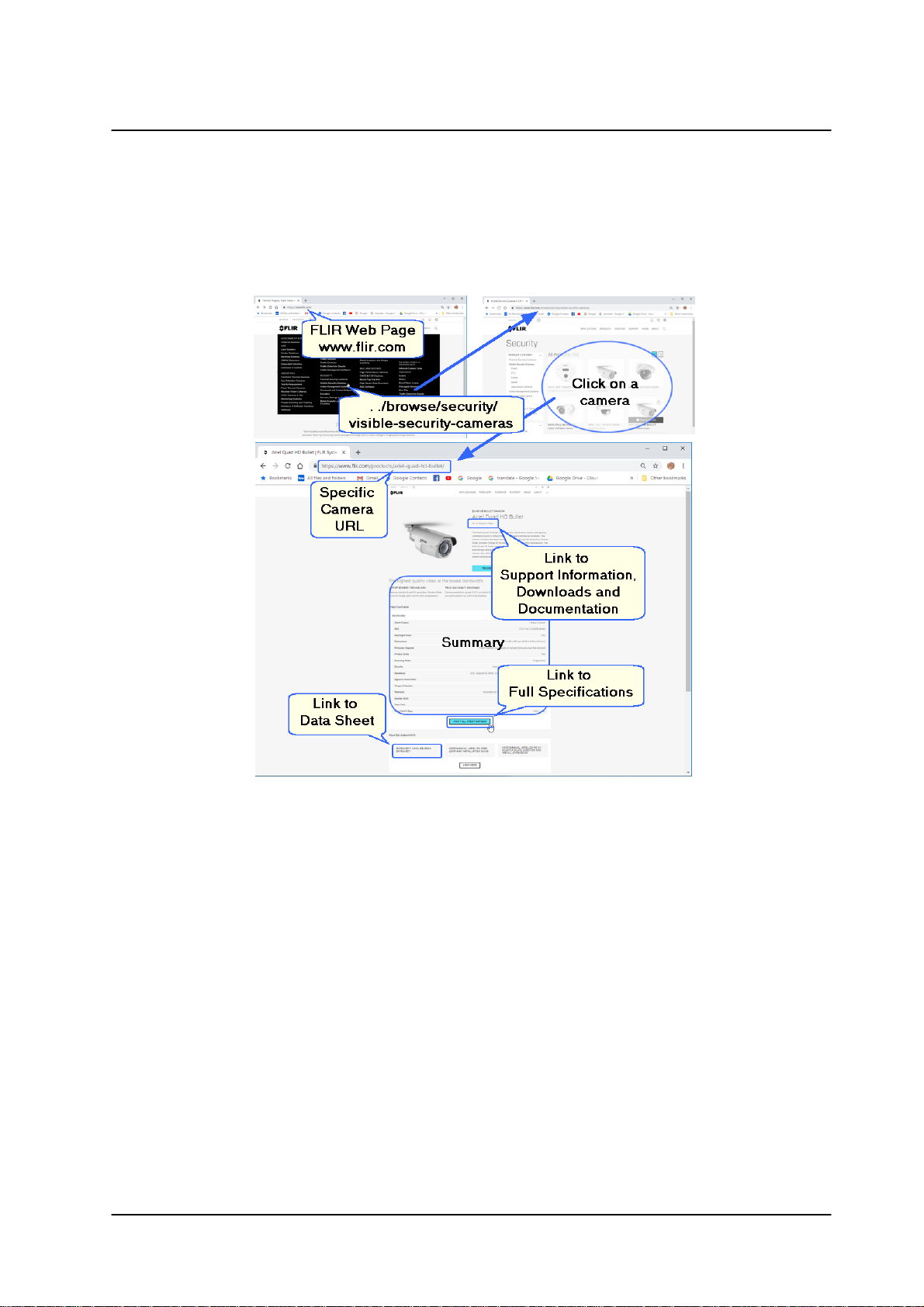
1.1 Accessing General Camera Information
Detailed Camera information is available on the FLIR website, accessible by navigating
to /Products, /Security, /Visible Security Cameras, and selecting the required camera.
CC-3103 User and Installation Guide
5December 12, 2018
Page 12

6
CC-3103 User and Installation Guide
December 12, 2018
Page 13
Introduction
·
3MP 1/2.8” Sony Exmor RS
CMOS sensor
·
Triple stream: 3MP +
1280x960 + 800x600
·
H.264 and MJPEG
compression
·
Low-lux mode without IR
·
True day/night (ICR)
·
Infrared LED illuminator
·
Digital WDR
·
3DNR image noise reduction
·
Backlight and highlight
compensation
·
Built-in web server
·
Supports Internet Explorer,
Edge, Chrome, and Firefox
browsers
·
HTTP streaming MJPEG
·
Motion detection event-driven
alarms
·
Tampering detection and
notifications
·
Two regions of interest
·
Gamma correction
·
White balance
·
8 privacy zones
·
802.1X and SSL/TLS
security protocols
·
SNMP v1/v2c/v3 and SNMP
traps
·
Up to 9 users
·
Built-in Mic
·
UPnP support
·
ONVIF© support
·
Alarm In/Out
·
Powered by 802.3af PoE
·
Support for audio-out (on
hardware revision 02.00)
2 Introduction
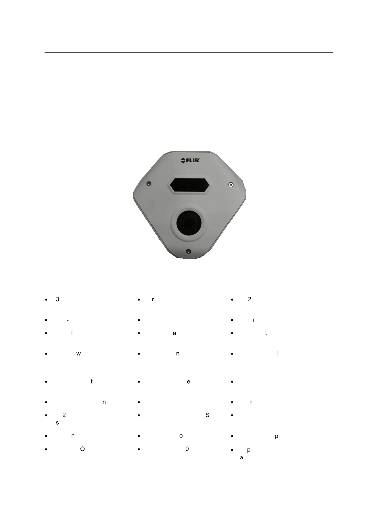
This User and Installation Guide is intended to help you physically install, configure settings for, and
operate the CC-3103 indoor/outdoor corner IP camera. The unit is a day/night camera with a 3MP
(2048x1536), 1/2.8” sensor, and includes an F1.8, 2.1mm fixed focal lens. The unit offers exceptional lowlight performance. It also includes a built-in microphone, audio out, alarm-in, and alarm-out connections.
The camera supports three streams: 2048x1536 (3MP), 1280x960, and 800x600 with H.264 or MJPEG
compression (3MP with H.264 only). The camera is powered by an 802.3af Power over Ethernet (PoE)
connection. It includes a microSD card slot for storing recordings and snapshots.
2.1 Features
CC-3103 Corner Camera
CC-3103 User and Installation Guide
7December 12, 2018
Page 14
Introduction
·
3MP 1/2.8” Sony Exmor RS
CMOS sensor
·
Triple stream: 3MP +
1280x960 + 800x600
·
H.264 and MJPEG
compression
·
Supports up to128GB
microSDXC card
·
IP66 enclosure with IK10
vandal-proof protection
Quantity
Description
1
CC-3103 corner camera
1
Bag containing six screws and six plastic anchors
1
T20 Torx wrench
2
Desiccants
1
CC-3103 Desiccants User Guide
1
CC-3103 Quick Install Guide
2.2 Package Contents
The unit package contains the following items:
Related Information:
·
DNA 2.2 User Manual (for more information, see Accessing General Camera Information.)
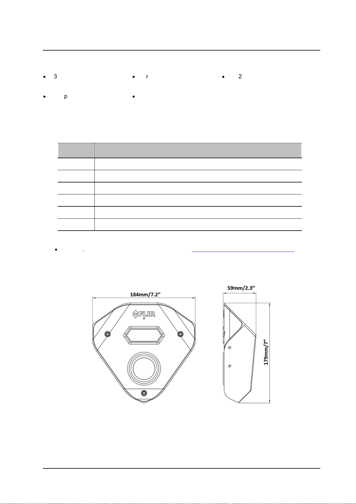
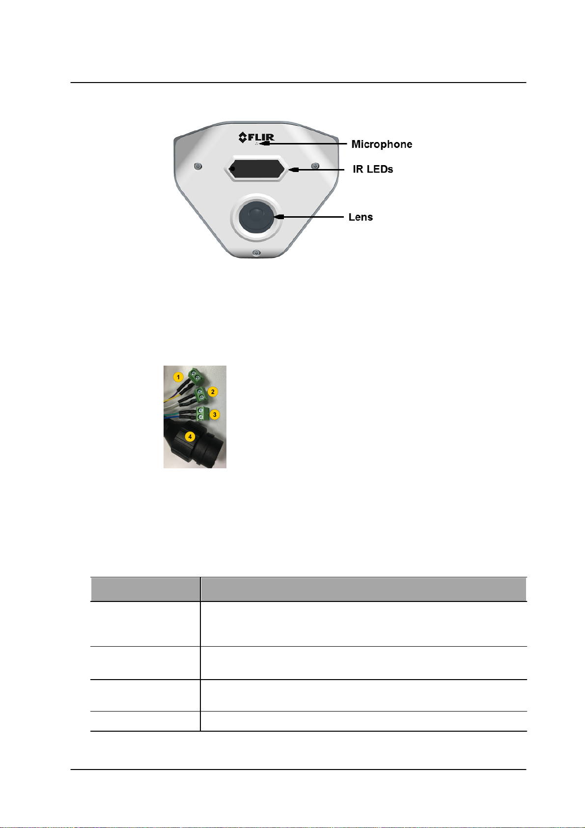
2.3 Hardware Description
Following are the CC-3103-01-I fixed focal camera’s dimensions.
CC-3103 Dimensions
The camera includes a built-in microphone and IR LEDs for true day/night operation.
CC-3103 User and Installation Guide
December 12, 20188
Page 15
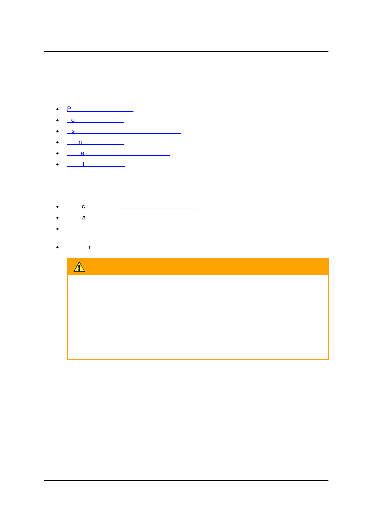
Introduction
CC-3103 System Cable
Cable Legend
Color
Function
Purple
Alarm IN
Yellow
Ground
White
Alarm OUT
Grey
COM
Blue
Audio OUT
Green
Ground
Item
Minimum System Requirement
Personal Computer
Intel® Pentium® IV, 2.4GHz or higher with >1GB RAM
Monitor display with minimum 1024 x 768 resolution
(NVIDIA GeForce 6 Series or ATI Mobility Radeon 9500)
Operating System
Windows 7, 8, 8.1, and 10 (all 64-bit versions)
Windows Server 2003, Windows Server 2008 (32-bit version)
Web Browser
Microsoft Internet Explorer 10 and above (32-bit version); Microsoft Edge
38 and above; Chrome v.55 and above; Firefox v.50 and above
Network Card
10Base-T (10 Mbps) or 100Base-TX (100 Mbps) operation
CC-3103 Callouts
The CC-3103-01-I camera includes a built-in system cable that includes an RJ-45 Ethernet jack and three
(3) two-wire leads (one audio out, one alarm-in and one alarm-out connection). The cable includes an LED
that flashes green to indicate power on and network activity. The LED is not illuminated if there is no
network activity.
2.4 System Requirements
CC-3103 User and Installation Guide
9December 12, 2018
Page 16

Introduction
Item
Minimum System Requirement
Viewer
ActiveX control plug-in for Internet Explorer; MJPEG viewer for Edge,
Chrome, and Firefox
CC-3103 User and Installation Guide
December 12, 201810
Page 17
3 Installation
Caution:
To avoid damage from overheating or unit failure, assure that there is sufficient temperature
regulation to support the unit’s requirements (cooling/heating). Operating temperature should be
kept in the range -40° to 50°C (-40° to 122°F), with no more than 90% non-condensing
humidity.
Attention:
Afin d'éviter tout dommage dû à une surchauffe ou toute panne de l'unité, assurez-vous que la
régulation de température est suffisante pour répondre aux exigences de l'unité
(refroidissement/chauffage). La température de fonctionnement doit être maintenue dans la
plage (-40° à 50°C/-40° à 122°F), sans condensation d'humidité supérieur à 90%.
This section describes how to install and connect the unit. It includes the following topics:
·
Pre-Installation Checklist
·
Powering the Camera
·
Inserting and Configuring the microSD card
·
Mounting the Camera
·
Connecting the Camera to the Network
·
Resetting the Camera
3.1 Pre-Installation Checklist
Before installing the unit, make sure that:
·
Instructions in the Document Scope and Purpose section are followed.
·
All related equipment is powered off during the installation.
Installation
·
Use best security practices to design and maintain secured camera access, communications
infrastructure, tamper-proof outdoor boxes, etc.
·
All electrical work must be performed in accordance with local regulatory requirements.
CC-3103 User and Installation Guide
11December 12, 2018
Page 18
Installation
Note:
An ITE PoE injector should be connected only to a PoE network inside a building and not routed
outside the building.
Caution:
1. This product must be connected only to a PoE network.
2. The PoE supply’s rated output is 48VDC, 0.2A.
3. If the camera is installed for outdoor use, the PoE supply must be installed with proper
weatherproofing.
4. As a Listed Power Unit, the PoE should be marked as “LPS” or “Limited Power Source”.
5. This product shall be installed by a qualified service person. Installation shall conform to all local
codes.
Attention:
1. Ce produit doit être connecté uniquement à un réseau PoE.
2. La puissance nominale de l'alimentation PoE est 48VDC, 0.2A.
3. Si la caméra est installée pour une utilisation extérieure, l'alimentation PoE doit être installé
avec l'étanchéisation appropriée.
4. Comme une unité d'alimentation «Listed», le PoE doit être marqué comme «LPS» ou «Limited
Power Source".
5. Ce produit doit être installé par un technicien qualifié. L'installation doit se conformer à tous les
codes locaux.
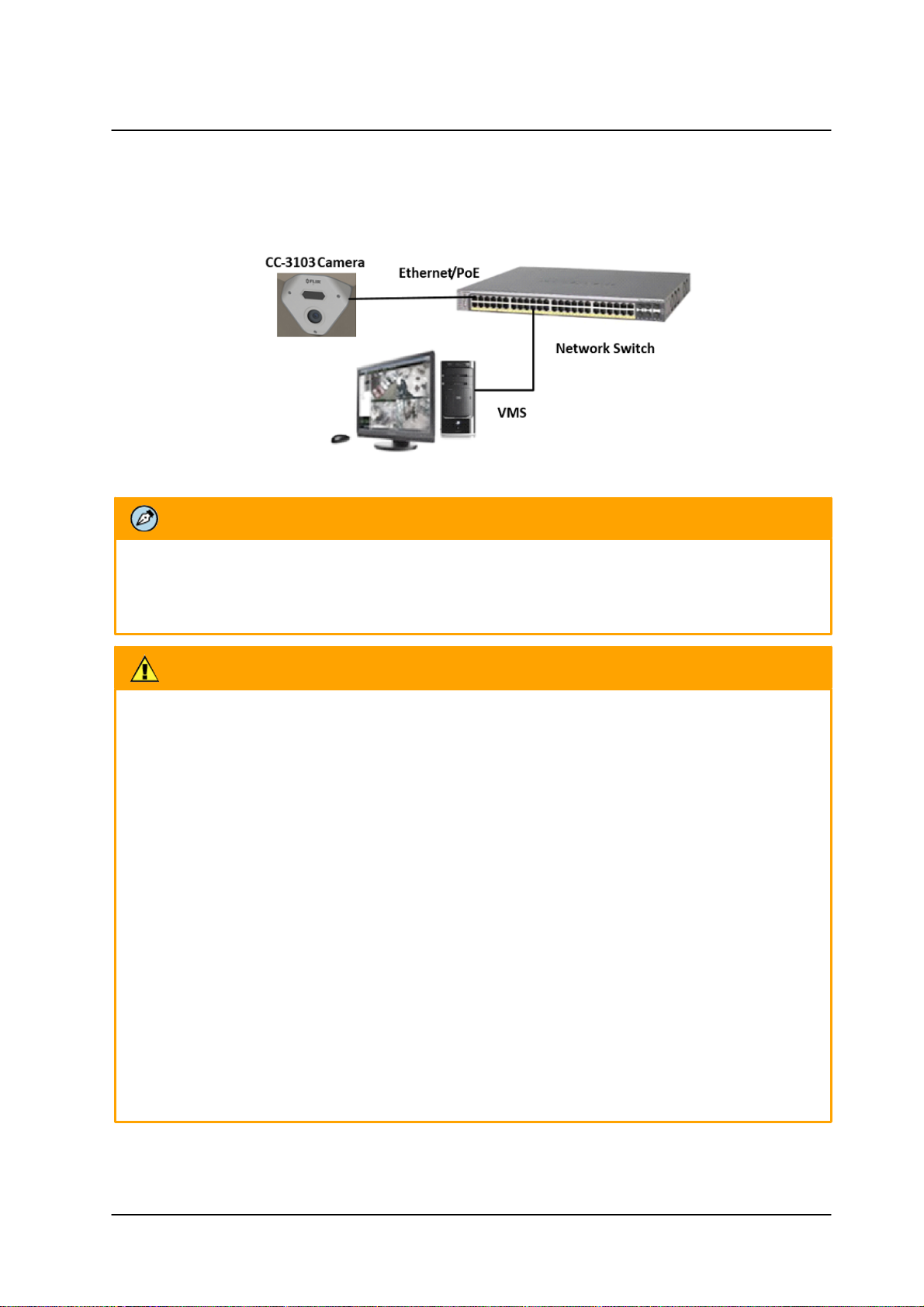
3.2 Powering the Camera
The camera is powered by an 802.3af PoE (Class 3) connection over the unit’s network cable.
System Connection
CC-3103 User and Installation Guide
December 12, 201812
Page 19

Installation
3.3 Inserting and Configuring the microSD Card
A microSD card (not supplied - (Min recommended 4GB, up to 128GB, Class 10)) must be inserted in the
camera in order to locally store a snapshot or recording triggered by an event. The microSD card slot is
located on a printed circuitboard inside the camera housing. To install a microSD card:
1. After removing the camera's cover, insert a microSDXC card in the card slot.
2. Be sure that a new desiccant is inserted inside the enclosure.
3. Replace the cover and screw the enclosure shut.
4. Verify that the card status is displayed as mounted in the System > Events Handler > SD Card
screen.
5. Configure the camera to store snapshots and recordings from the System > Events Source
screens.
3.4 Mounting the Camera
The CC-3103 camera is designed to be mounted against the ceiling and two walls in the corner of a room
for optimal viewing of the scene. The camera enclosure includes screw holes on three sides.
Required items:
1. Electric screwdriver
2. Phillips screwdriver
3. Electric drill
4. Hammer
5. Six plastic screw anchors (supplied)
6. Six screws (supplied)
CC-3103 User and Installation Guide
13December 12, 2018
Page 20
Installation
To mount the camera
1. Mount the camera at the site according to your surveillance requirements. Be sure to have the
required accessories and tools available.
2. Remove the protective plastic covering the electronics in the camera body.
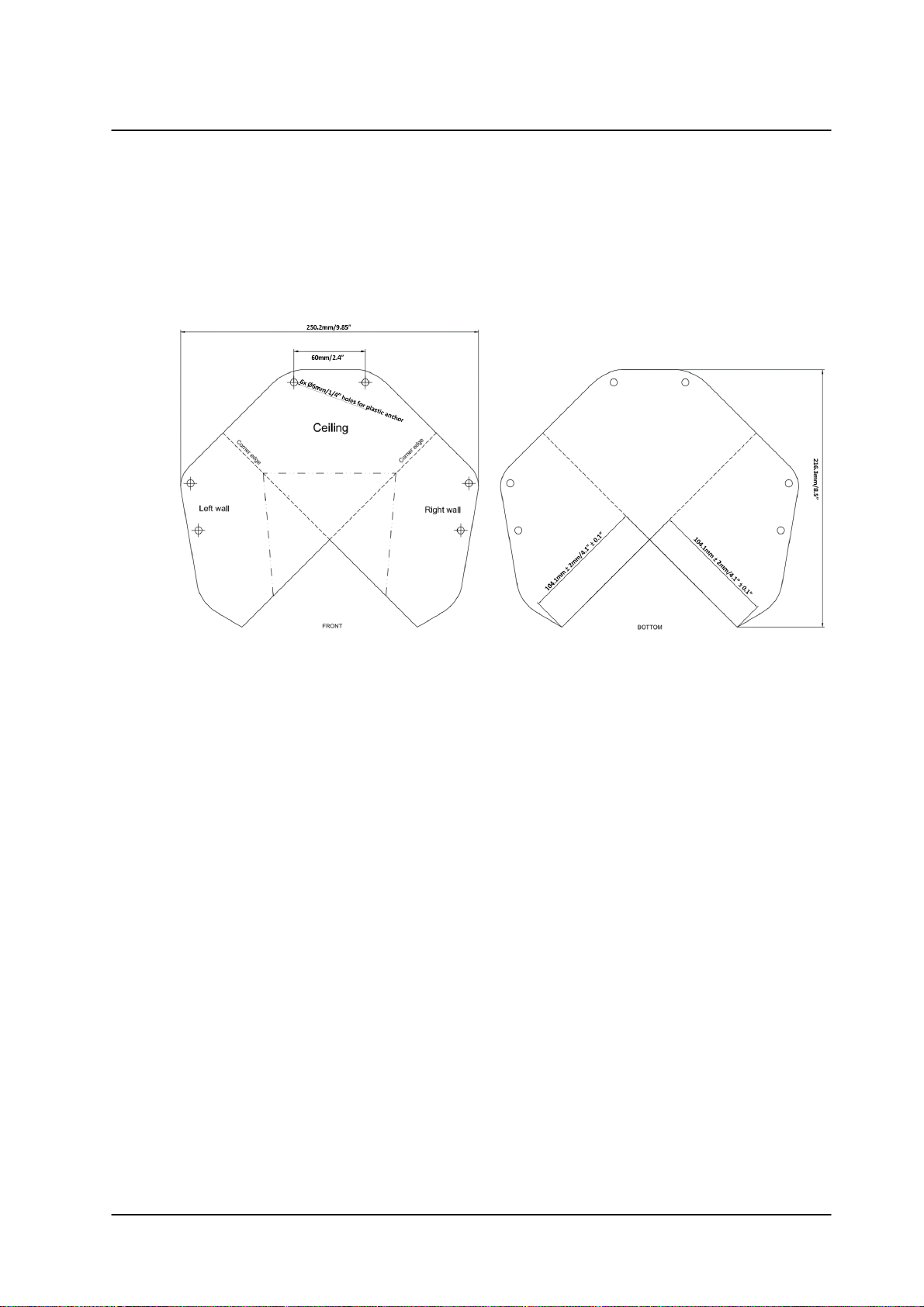
3. Using the provided template, mark the drill locations on the ceiling and wall.
Drill Template
4. Drill a hole in the ceiling to insert the system cable.
5. Drill holes into the surfaces for the screws.
6. Hammer the screw anchors into place.
7. Attach the system cable to the network switch.
8. Align the screw holes on the camera body with the markings on the surface.
9. Using the electric screwdriver, screw the camera body into the surfaces.
10. Verify that you have inserted new dessicant inside the camera body.
11. Replace the protective plastic covering over the camera's electronics.
12. Attach the safety lanyard from the camera body to the camera cover.
13. Using the Torx wrench, screw the camera cover over the camera body.
CC-3103 User and Installation Guide
December 12, 201814
Page 21
Installation
Note:
Remember to insert new desiccant inside the camera enclosure before screwing it shut.
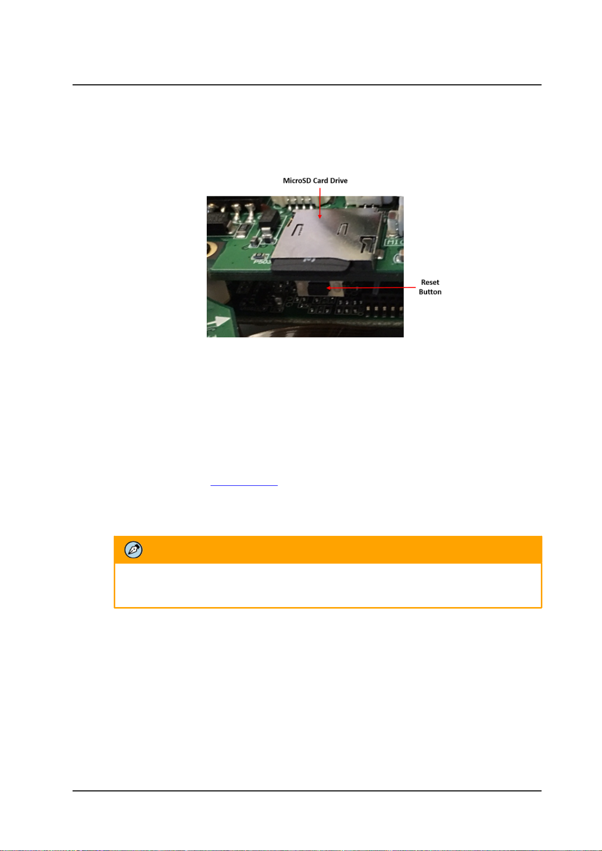
3.5 Resetting the Camera
The camera includes a reset button, which is located on a printed circuit board inside the camera housing,
along with the camera’s microSD card slot.
Camera Reset/MicroSD Cover
To reboot the camera
1. Using the supplied Torx wrench, open the camera enclosure. The reset button and microSD card
drive are exposed.
2. Press the reset button for approximately five seconds. The unit reboots.
To restore factory defaults using the reset button
Note: It is recommended to back up configuration prior to resetting the camera in order to keep
configuration and settings, which can be re-applied after the factory default.
For more information see: Import Settings
Note: If factory defaulting due to a camera malfunction, it may be beneficial to contact support prior to
the default to allow them to better resolve the issue.
1. Press the reset button continuously for 30 seconds. The unit restores factory defaults.
3.6 Connecting the Camera to the Network
To view and configure the camera via a LAN, you must attach the camera via the network switch or router
to the same subnet (network segment or VLAN) as the computer that manages the unit. If the PC is on a
different subnet than the camera, you will not be able to access the camera via a web browser.
If there is a DHCP server on the network, it is recommended to use FLIR’s Discovery Network Assistant
(DNA) utility to search for and change the camera’s initial IP address. If there is no DHCP server on the
network, the camera will initialize with the default IP (192.168.0.250). You can then use DNA to change its
IP address.
CC-3103 User and Installation Guide
15December 12, 2018
Page 22
Installation
3.6.1 Configuring Communication Settings
To configure communication settings on the camera
1. Connect the camera to the network on the same VLAN/LAN as the workstation.
2. If the network supports the default, open the DNA utility by running dna.exe which can be
downloaded from the FLIR Website - see Accessing General Camera Information.
3. In the DNA application, click the DNA button.
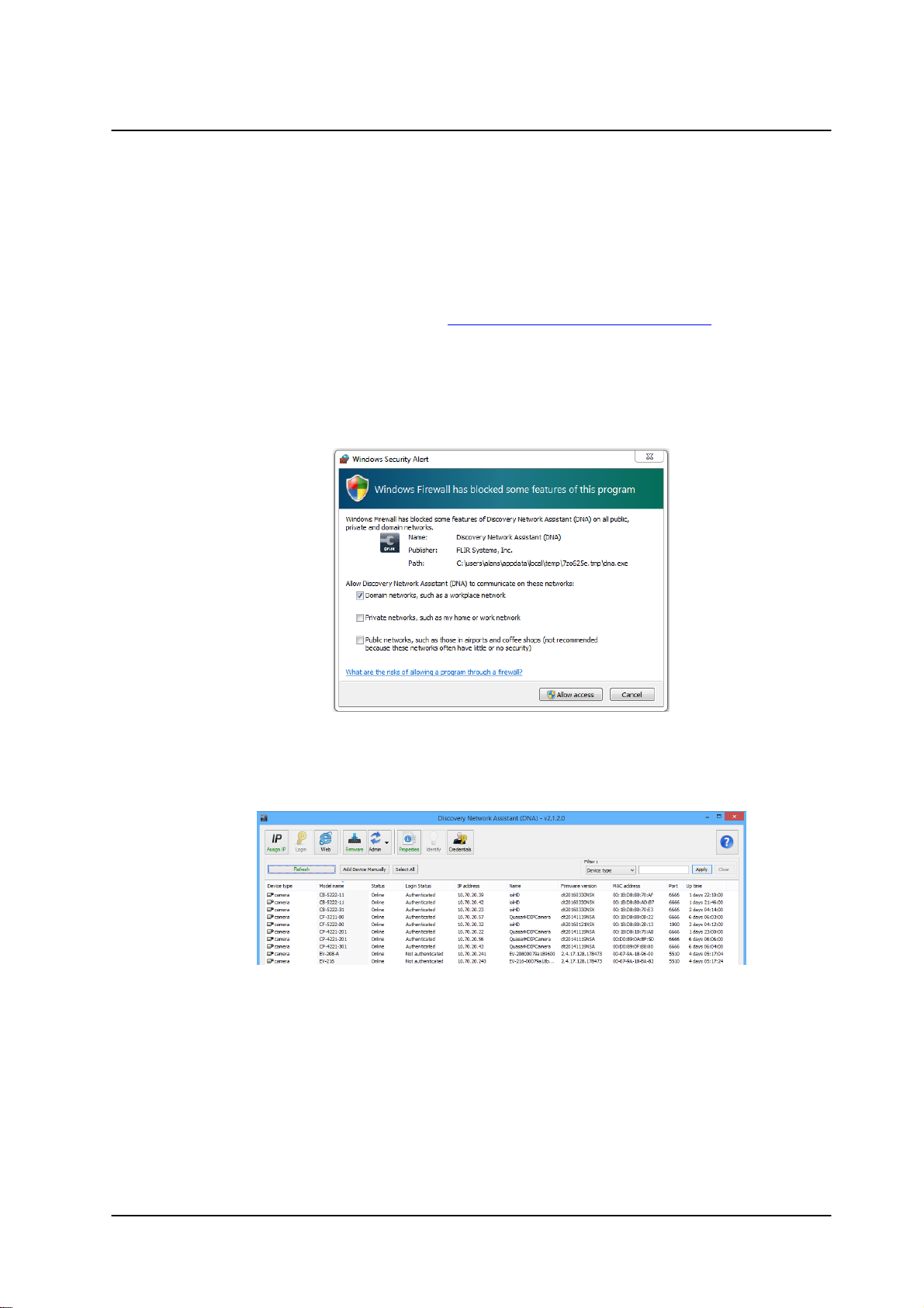
4. If the Windows Firewall is enabled, a security alert window pops up.
5. To continue, click Allow Access. Latitude users should consult the Latitude Installation
Instructions on disabling the Windows Firewall.
Windows Firewall Screen
6. Click Assign IP. All the discovered IP devices will be listed in the page, as shown in the figure
below. The camera’s default IP Address is automatically supplied by the DHCP server.
Discovered IP Devices
CC-3103 User and Installation Guide
December 12, 201816
Page 23
Installation
Tip:
Record the camera’s MAC address for future reference.
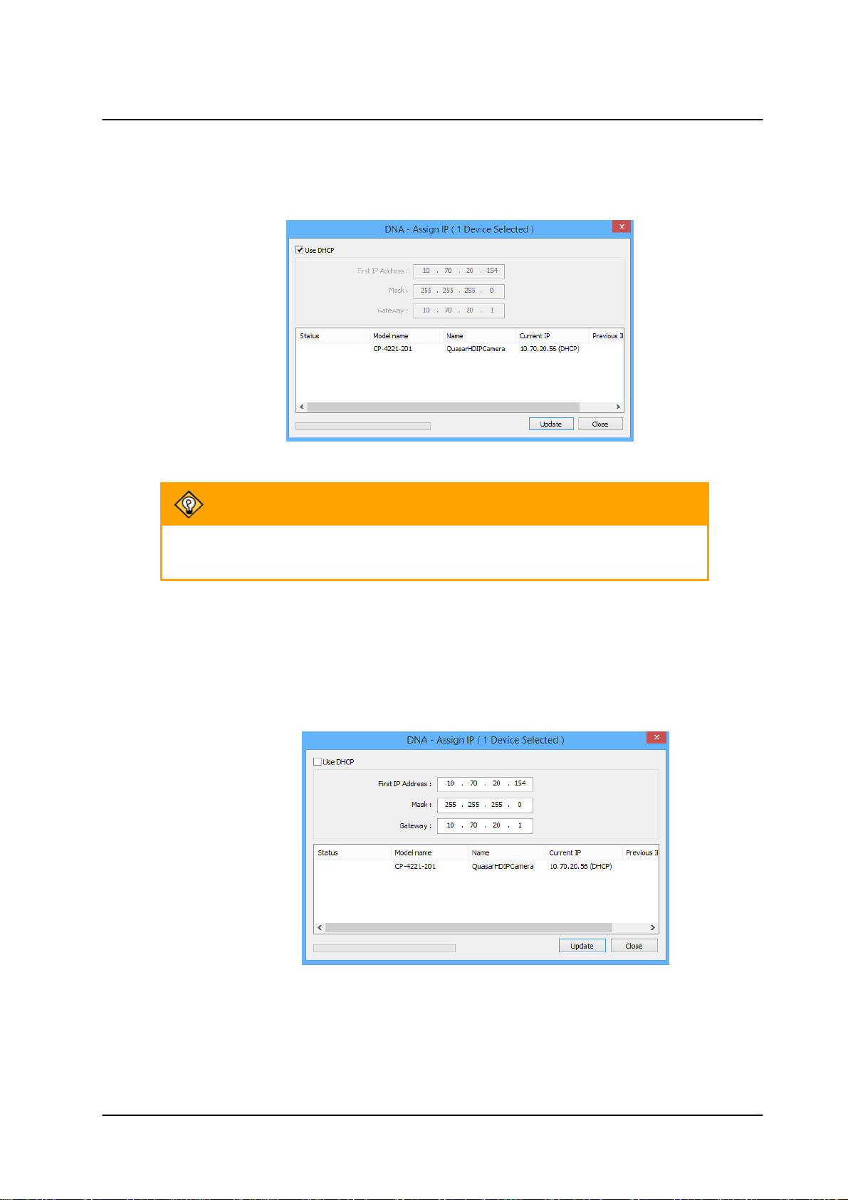
7. Right-click the camera whose network property is to be changed. From the context menu that
opens, select Assign IP. The Assign IP dialog is displayed.
DNA Assign IP – Use DHCP Dialog Box
8. To access DNA, do one of the following:
a. For DHCP (not supported by Latitude):
i. Select Use DHCP. Do not use for Latitude.
ii. Click Update and wait for status.
b. For Static IP (recommended for Latitude users):
DNA Assign IP – Static IP Dialog Box
CC-3103 User and Installation Guide
17December 12, 2018
Page 24
Installation
Note:
1. Both the user name and password are case-sensitive.
2. It is strongly advised that administrator’s password be altered for security
reasons.
i. Do not select the Use DHCP checkbox. This is recommended for security purposes
and for and Latitude users. In the IP Address, Gateway, and Netmask, enter the
respective LAN/VLAN (optional DNS) values.
ii. Click Update and wait for OK status to be displayed.
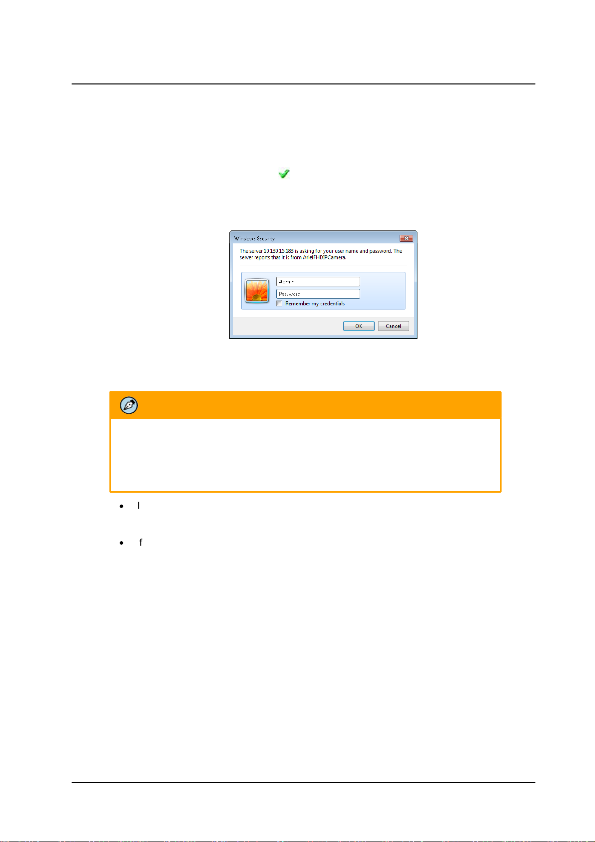
9. Right-click and select Web to directly access the camera via a web browser. The web browser
opens on the unit’s Login dialog box.
Login Dialog Box
10. Log into the unit with the default user name Admin and password 1234.
·
If the User Account Control dialog box opens and requests you to install the
install.cab file, click Yes.
·
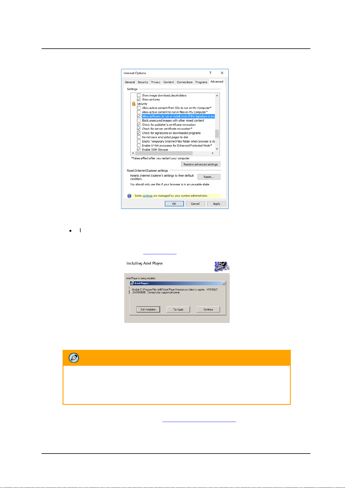
If the ActiveX installation is not successful after performing the previous step, in the Internet
Explorer Tools > Internet Options > Advanced Security section, select the Allow software
to run or install even if the signature is invalid checkbox. Uncheck the checkbox after
installing ActiveX. Then click OK.
CC-3103 User and Installation Guide
December 12, 201818
Page 25
Installation
Note:
If the password is changed and the Latitude AdminCenter Discovery feature is in use,
deselect all other proprietary types. Select Dvtel Ariel Line as the Unit Type so that the
new password can be configured in the Discovery > Add Unit Manually setting.
IE Tools > Internet Options > Advanced Window
·
If you are using ActiveX, but do not have the Microsoft Visual C++ 2008 Redistributable
libraries installed on your PC, the following error message is displayed. In this case,
download and install the vcredist_x86.exe file from the Internet, or contact your
Network Administrator or FLIR Support.
MS Visual C++ 2008 Redistributable Error Message
11. If a popup message appears for running the ActiveX add-on, click Allow.
Additionally, you can change the camera’s network properties (either DHCP or Static IP) directly
from the camera’s web interface on the System > Network > General screen.
CC-3103 User and Installation Guide
19December 12, 2018
Page 26
Installation
Note:
If you have previously installed a web player application on the PC, you should
delete the existing web player from the PC before accessing the camera.
Note:
To download the DNA and for detailed guidelines about DNA and its usage, refer to the DNA User
Manual. See Accessing General Camera Information.
12. Install the web player.
3.6.2 Using DNA to Access the Camera
To view and configure the camera via a LAN, you must attach the camera via the network switch or router
to the same subnet (network segment or VLAN) as the computer that manages the unit. If the PC is on a
different subnet than the camera, you will not be able to access the camera via a web browser.
If there is a DHCP server on the network, it is recommended to use FLIR’s Discovery Network Assistant
(DNA) utility to search for and change the camera’s initial IP address.
DNA is a user-friendly utility that is designed to easily discover and configure FLIR Professional Security
edge devices on a network. The DNA tool has a simple user interface and does not require any installation.
The software is provided as a single, standalone executable. It runs on any PC.
DNA provides a central location for listing all the supported FLIR Professional Security camera models
accessible over the network. Once listed, each camera can be right-clicked to access and change the
network settings. If the network settings are changed for some reason, a new search will relist the units.
The units may then be configured via the web interface.
If FLIR’s Latitude VMS is being used, configure the unit with a static IP address rather than with DHCP.
This ensures that the IP address will not automatically change in the future and interfere with configurations
and communication.
If there is no DHCP server on the network, the camera will initialize with the default IP (192.168.0.250). You
can then use DNA to change its IP address.
CC-3103 User and Installation Guide
December 12, 201820
Page 27
3.6.3 Configuring the Unit’s Initial IP Address
Note:
1. It is possible to set the IP address without changing the subnet.
2. The unit and the PC must be physically connected on the same network segment.
Use the FLIR DNA utility to discover the unit on the network and to set the unit’s initial IP address.
·
If the camera is located on a network that uses a DHCP server, or is managed by FLIR’s Horizon
or Meridian VMS and is configured as a DHCP server, configure the camera with DHCP-enabled.
Horizon or Meridian automatically assigns the camera an IP address.
·
If the camera is located on a network that does not use a DHCP server, or is managed by FLIR’s
Latitude VMS, manually enter its IP address in the DNA utility.
To manage the camera using Horizon, Meridian, or on a DHCP-enabled network
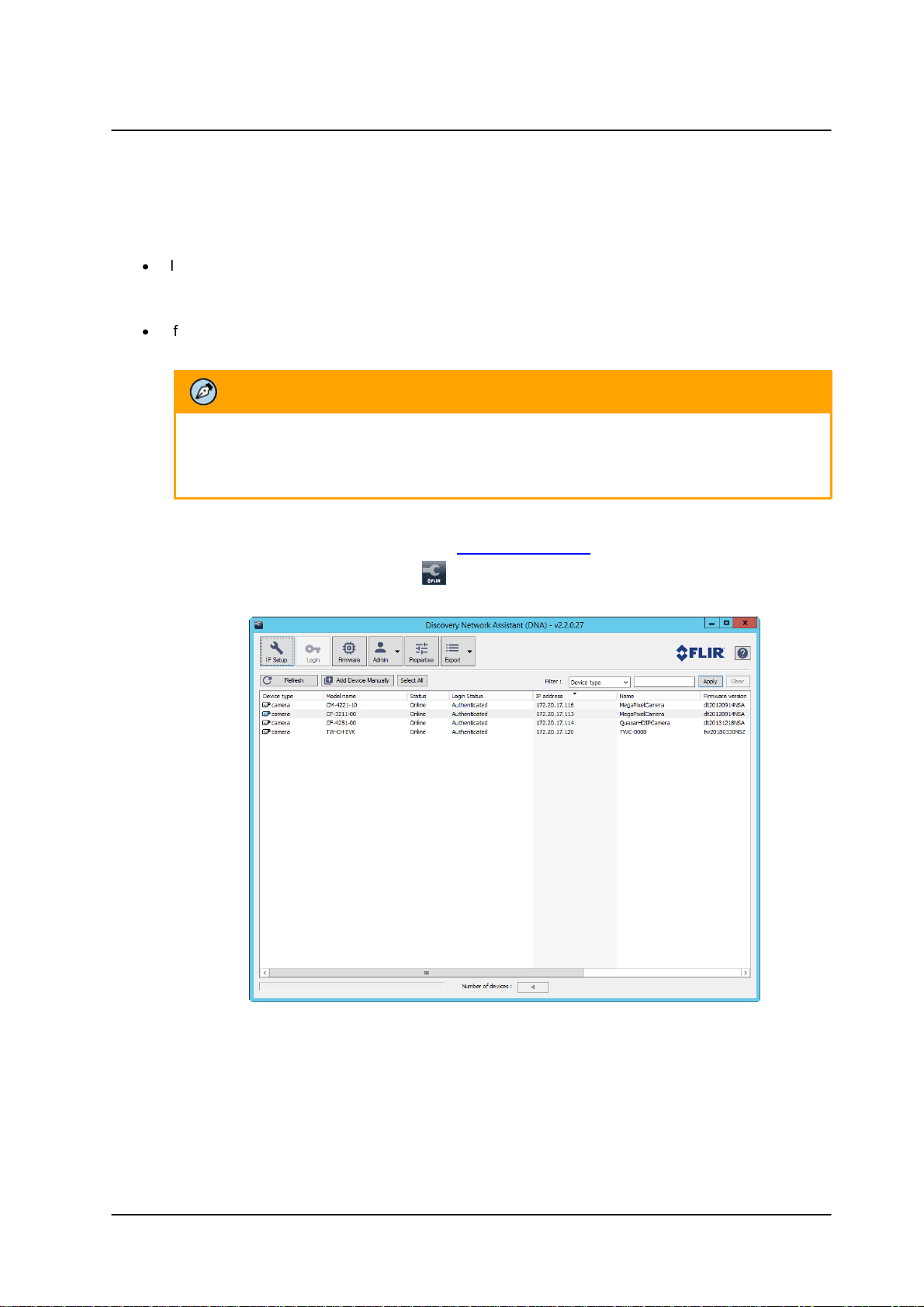
1. Download the DNA from the FLIR website: Website Resources
Installation
2. Run the dna.exe file by clicking the icon. The DNA application opens and the device is
displayed in the window.
DNA Discovery Window
CC-3103 User and Installation Guide
21December 12, 2018
Page 28
Installation
Note:
The user name and password are case-sensitive.
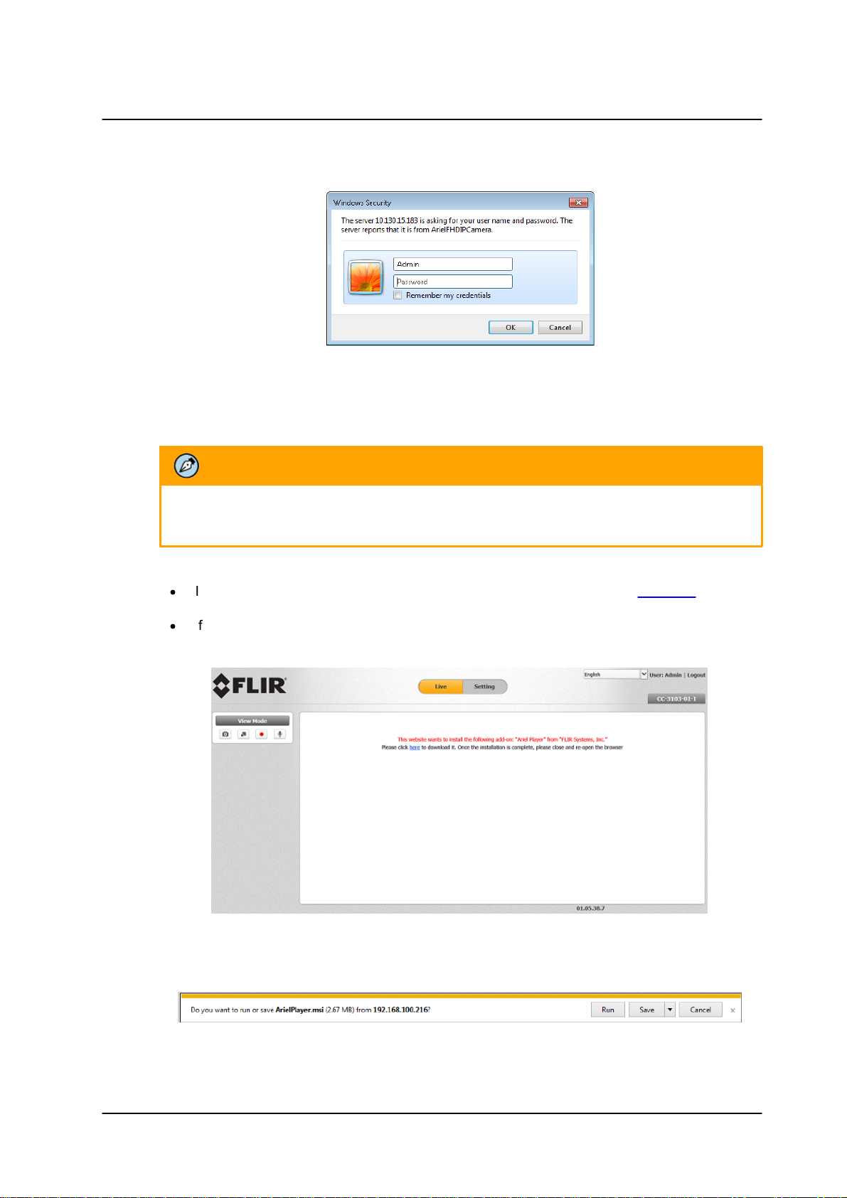
3. Double click on the unit in DNA’s Discover List. The CC-3103 Login window opens.
Login Window
4. If the camera cannot connect to a DHCP server, the unit initializes with the default IP address
(192.168.0.250).
5. Enter the default User Name (Admin) and Password (1234).
6. Click Login. The camera’s web interface opens.
·
If your browser is Edge, Chrome or Firefox, the video is displayed in the Live View window.
·
If your browser is Internet Explorer, a message is displayed, requesting you to install a plugin.
Web Interface with Internet Explorer Browser
7. Click “here” on the screen to download the Ariel Player plug-in. The Ariel Player plug-in information
bar opens.
Run Ariel Player Plug-in Information Bar
CC-3103 User and Installation Guide
December 12, 201822
Page 29
Installation
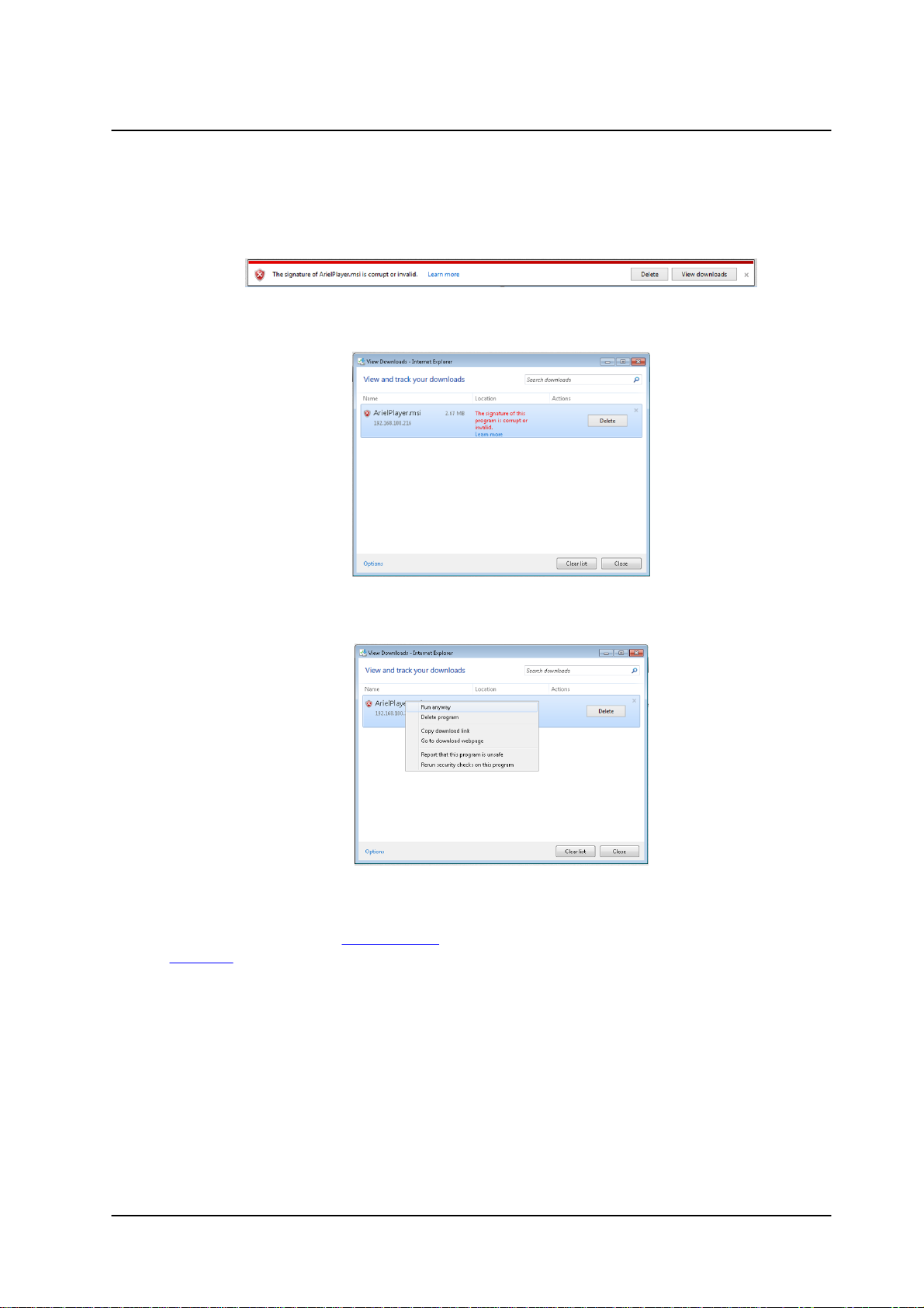
When using Internet Explorer in closed networks, occasionally the browser will not install the Ariel
Player on the client PC because it cannot verify the Ariel Player’s digital signature. This may be
because the local certificate is out of date, invalid or missing. The following message is displayed:
Corrupt/Invalid Signature
a. Click View downloads. The View Downloads screen opens.
View Downloads Screen
b. Right-click on the ArielPlayer.msi file.
Run Anyway Option
c. Select “Run anyway”. The normal installation process starts.
8. Follow the instructions in Appendix 10.5 for installing the Player. After installing the Player, the
Live View is displayed.
CC-3103 User and Installation Guide
23December 12, 2018
Page 30
Installation
Note:
The user name and password are case-sensitive.
To manage the camera using Latitude or on a network with static IP configuration
1. Download the DNA from the FLIR website: Website Resources
2. Run the dna.exe file by clicking the icon. The DNA application opens and the device is
displayed in the DNA Discovery window. See Figure: DNA Discovery Window.
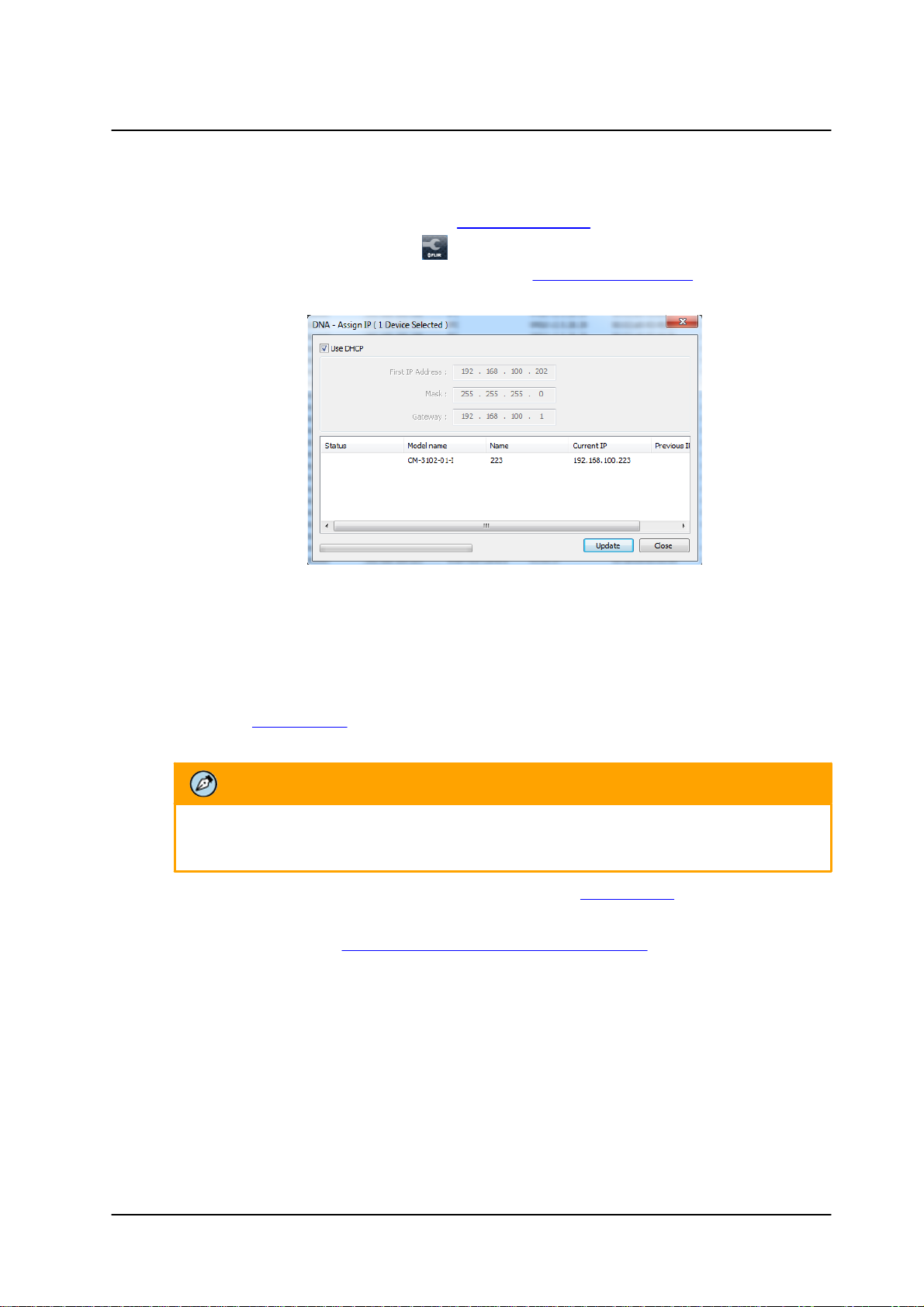
3. Select the unit by right-clicking it. The DNA - Assign IP window is displayed.
DNA Assign IP - Use DHCP Screen
4. Uncheck Use DHCP.
5. Enter the unit’s default IP address (192.168.0.250), Subnet mask, and Gateway IP address in the
respective field.
6. Click Update. The unit reboots with the new settings.
7. Click on the unit in DNA’s Discover List. The camera’s Login window opens.
See Figure: Login Window.
8. Enter the default User Name (admin) and Password (admin).
9. Click Login. The camera’s web interface opens. See Figure: Web Interface.
10. Click the on-screen message to install the Ariel Player plug-in. The Ariel Player Plug-in message
is displayed. See Figure: Ariel Player Plug-in Download Information Bar.
CC-3103 User and Installation Guide
December 12, 201824
Page 31

Installation
Note:
The user name and password are case-sensitive.
3.7 Settings
Device and client PC parameters are set from the Settings tab in the navigation bar. Upon clicking
Settings, the Settings menu is displayed in the sidebar. Three sections are displayed: System,
Streaming, and Camera.
Unexpanded Sidebar
3.8 Configuration and Operation
The Ariel Gen II camera is provided with a browser-based configuration interface for video playback and
recording. In this chapter, information about main page introduction, system related settings and camera
settings are described in detail.
Additionally, if FLIR’s Latitude VMS is used, many of the configurations and features of FLIR’s VMS provide
configuration and automation of the camera.
This section includes the following information:
·
CC-3103 Web Interface
·
Live View
·
System Tab
·
Streaming Tab
·
Camera Tab
·
Logout
3.8.1 CC-3103 Web Interface
The camera's web interface can be configured and operated from a 32-bit version of Microsoft Internet
Explorer 10 and above, Microsoft Edge 38, Chrome v.55 and above, or Firefox v.50 and above.
To access the unit via the web browser
1. Open the browser.
2. Enter the unit’s IP address in the browser’s address bar.
3. Press the ENTER key on your PC keyboard. The unit’s Login window is displayed.
See Figure: Login Window.
4. Enter the user name (default: Admin) and password (default: 1234) to log into the system. The
unit’s web interface opens. See Figure: Web Interface.
CC-3103 User and Installation Guide
25December 12, 2018
Page 32

Installation
5. If you are using the system for the first time or you have uploaded a new firmware version, click the
message displayed on the screen to download to allow the MediaPlayer Control
Module.exe plug-in.
6. Click Allow. The Windows Installer opens and the Ariel Player Wizard dialog box is displayed.
Follow instructions in the Configuring the Unit’s Initial IP Address section.
7. Configure camera settings after setting the unit's IP address.
Live View Screen with Callouts on Internet Explorer Browser
The following information is displayed in the upper right corner of the GUI:
·
Language Bar – Select the language for the web interface: English, Arabic, Czech, Simplified
Chinese, Traditional Chinese, French, German, Hungarian, Italian, Japanese, Polish, Portuguese,
Russian, or Spanish.
·
User Name – Displays the user name. By default, Admin is displayed.
·
Logout Link – Click Logout to exit the web interface.
·
Model Number – Displays the model number.
Above the Live View window, the selected video format, date and time are displayed. Below the Live
View window, the firmware version is displayed.
CC-3103 User and Installation Guide
December 12, 201826
Page 33

Installation
Item
Description
ActiveX/MJPEG Button
Click ActiveX to use Internet Explorer or click MJPEG to using Edge,
Chrome, or Firefox. Displayed only with Internet Explorer browser.
Snapshot button
Click the button to take a snapshot.
Full screen button
Click the button to display the live view in full-screen mode. To switch
back to Live View mode, right-click on the screen and click Normal
Display, or press the ESC key on your keyboard. Displayed only with
Internet Explorer browser.
Manual recording
button
The button indicates the recording status: red when recording is On or
gray when recording is Off . Displayed only with Internet Explorer
browser.
Mic button
Click the button to listen to audio at the remote site. This function is
available only to an Operator or Administrator. Click the button to switch it
on/off. The button allows the user to listen to audio streaming over the web
if (a) audio is enabled and (b) if an audio event is enabled and triggered by
exceeding the threshold. Settings are configured on the Audio screen.
Displayed only with Internet Explorer browser.
Audio-out button
Click the button to speak from a client connected microphone
through a speaker, wired to the camera audio-out terminal.
To the left of the Live View window, the View Mode buttons are displayed. All buttons are displayed in
Internet Explorer browsers. Only the Snapshot button is displayed in Microsoft Edge, Chrome, and
Firefox.
From the Navigation Bar, select one of these tabs:
·
Live – Displays the Live View screen
·
Settings – Displays the Settings sidebar
CC-3103 User and Installation Guide
27December 12, 2018
Page 34

Installation
Note:
In order to save recordings on your PC, Internet Explorer should be run as Administrator.
3.8.2 Live View
To start Live View
1. From the Navigation Bar, click Live View. The Live View screen opens.
Live View Screen with Internet Explorer Browser.
2. Click one of the buttons listed above for the desired action from the Live View toolbar.
The following sections include the following topics:
·
Recording
·
Capturing a Picture
·
Viewing Live Video from a Media Player
3.8.2.1 Recording
Manual recordings (which are triggered from the Live View screen) are stored on the PC.
To start recording a Live View scene
1. Click the red Manual Recording icon on the toolbar. The camera starts recording. A red dot
is displayed in the upper right corner of the Live View window, under the date and time display.
2. Select the directory and folder to save the video, which is an .avi file.
3. Click the icon to stop recording. The icon turns gray .
To playback a Live View recording
1. Open the folder on the PC where the recording is stored.
CC-3103 User and Installation Guide
December 12, 201828
Page 35

Installation
Note:
In order to save snapshots on your PC, Internet Explorer should be run as Administrator.
2. Select the file.
Recordings that are triggered by events (such as motion detection) are stored on a microSDXC card, which
can store up to 128GB of data. The card is not included.
To view a triggered event recording
1. In your browser, enter the camera’s FTP address (ftp://camera_ip/).
2. Enter the Admin user name and password.
3. Open the folder for the event according to the type of event (motion detection, tampering, etc.).
Files are displayed chronologically according to most recent date.
4. Select the file.
3.8.2.2 Capturing a Picture
It is possible to capture a picture as a snapshot in Live View mode and save it on your PC as a .jpeg or
.png file image.
To capture a snapshot in Live View mode
1. In Live View mode, click the Snapshot button on the toolbar to capture the live pictures.
To view a Live View snapshot
1. Open the folder on the PC where the snapshot is stored.
2. Select the file.
Snapshots that are triggered by events (such as motion detection) are stored on the camera’s microSD
card, which can store up to 128GB of data. The card is not included.
To view a triggered event snapshot
1. In your browser, enter the camera’s FTP address (ftp://camera_ip/).
2. Enter the Admin's user name and password .
3. Open the folder for the snapshots. Files are displayed chronologically according to most recent
date with an indication of the type of event, for example 20170118122205_motion_1.mp4.
4. Select the file.
CC-3103 User and Installation Guide
29December 12, 2018
Page 36

Installation
Note:
1. It is also possible to change the syntax on the RTSP page, although this is not
recommended if the camera is attached to a VMS.
2. Verify that the resolution entered in URL string agree with the resolution set in
the Streaming > Video Settings screen.
3.8.2.3 Viewing Live Video from a Media Player
The Live View main stream and sub-stream can be viewed with a media player, such as VLC (download
from http://www.videolan.org/vlc/index.html). Streams can be viewed for the three channels and two video
encoding formats (H.264 and MJPEG).
The camera supports sending unicast and multicast streams via the RTSP protocol. Unicast streams
include the suffix “stream” followed by the stream number without a space. Multicast streams include the
suffix “streamXm”, where “X” is the stream number (1, 2 or 3).
To view a media stream with VLC
1. Open VLC.
2. From the Media tab, select Open Network Stream. The Open Media screen is displayed.
VLC Open Media Screen
3. In the Network tab, enter the URL for the stream in the address bar:
·
The syntax for entering the URL in the media player for the main stream is:
rtsp://(camera IP address)/(Unicast stream 1) or (Multicast stream 1). For example,
rtsp://192.168.0.250/stream1 for a unicast stream.
·
The syntax for entering the URL in the media player for the second stream is: rtsp://(camera
IP address)/(Unicast stream 2) or (Multicast stream 2). For example, rtsp://
192.168.0.250/stream2 for a unicast stream.
·
The syntax for entering the URL in the media player for the third stream is:
rtsp://(camera IP address)/(Unicast stream 3) or (Multicast stream 3). For example, rtsp://
192.168.0.250/stream3m for a multicast stream.
CC-3103 User and Installation Guide
December 12, 201830
Page 37

Installation
Basic Configuration
User Accounts
Network
Events Source
Events Handler
Date & Time
Audio
Firmware
Basic Operations
OSD
4. Click Play. The video stream is displayed in the media player. If available, audio will also be
streamed (CC-3103-11-I only).
Media Player Screen
3.8.3 System Tab
The System tab is used for configuring essential system settings. Click the System tab to expand the
menu.
The CC-3103-01-I includes the following System menu:
CC-3103-01-I System Menu
Click the link to open the tabs for the various functions:
3.8.3.1 Basic Configuration
The Basic Configuration tab includes the following screens:
CC-3103 User and Installation Guide
31December 12, 2018
Page 38

Installation
3.8.3.1.1 Date & Time
The current time is displayed in the Current Camera Time text box. To set the date and time, select Basic
Configuration > Date & Time. The Date & Time screen is displayed.
Date & Time Screen
To change the date and time
1. Select one of the following options
·
Manual Settings – Enter the date and time in the respective field.
·
Synchronize with PC – Enter the date and time in the respective field.
·
Synchronize with NTP Server – Selecting this option opens the NTP Settings section:
NTP Setting Section
a. Enter the following details in the NTP Setting section:
·
Enable – From the drop-down list, select Manual to set the NTP server manually,
or From DHCP Server to set the time according to the network DHCP server.
·
Server Address – Enter the IP address for the NTP server.
·
Synchronization Period – Select a number between 1-24 for the frequency (in
number of hours) that the camera will synchronize with the NTP time server (i.e.,
every one hour, every two hours, etc.).
2. In the Time Zone Setting section, from the Area drop-down list, select your local time zone.
3. Click Save. The new time is displayed in the Current Camera Time text box.
CC-3103 User and Installation Guide
December 12, 201832
Page 39

3.8.3.1.2 Audio
The Audio screen is used for configuring Audio In and Audio Out settings.
Basic Configuration > Audio Screen
To enable audio settings
1. From the Enable drop-down list, select ON.
2. From the Encoding drop-down list, select G.711 a-law, G.711 µ -law, or AAC. The default is AAC.
(Audio In Only)
3. From the Level drop-down list, select High, Mid, or Low.
4. If required, adjust the Audio Out settings.
Note: Audio OUT is only supported for units with Hardware revision 02.00
Installation
3.8.3.1.3 Firmware
The Firmware screen displays and is used to update the system firmware, and to display the hardware version, product name (model number), product serial number, and product MAC address. To access the Firmware screen, select Basic Configuration > Firmware.
Firmware Screen
To update system firmware
1. Click Browse to locate the firmware file.
Note: The folder includes a checksum file, which can be used to check file validity using the checksum
validation software of your choice.
2. Select the file. The file name is displayed (for example, ArielFHD_20161230).
3. Click Upgrade. The upgrade process takes about three minutes. After the firmware has upgraded
successfully, the camera reboots.
CC-3103 User and Installation Guide
33December 12, 2018
Page 40

Installation
Caution:
Selecting Full factory defaults causes the camera to lose all network settings.
Attention:
Sélection par Défaut Complet d'Usine entraîne la caméra de perdre tous les paramètres réseau.
Rebooting Complete Dialog Box
4. Click OK. The Live screen opens.
5. If your browser requests you to close the window, click Yes. The window closes.
6. Open a new window and enter the camera’s URL. The Login window opens. See Figure: Login
Window.
7. Enter your user credentials and log into the camera. The new firmware version is displayed in the
Firmware Version text box.
3.8.3.1.4 Basic Operations
The Basic Operations screen is used for the following functions:
·
Setting the TV format
·
Importing settings from another unit
·
Exporting settings to another unit
·
Rebooting the camera
·
Restoring partial factory defaults
·
Restoring full factory defaults
Basic Operations Screen
Click Reboot to save configured settings.
Click Partial factory defaults to restore factory defaults, but retain network settings (IP address, netmask
address, and gateway address), TV format, and image rotation settings.
Click Full factory defaults to restore factory defaults, including network settings.
To select the TV format
CC-3103 User and Installation Guide
December 12, 201834
Page 41

1. Select Basic Configuration > Basic Operations. The Basic Operations screen is displayed.
Note:
Clicking Partial factory defaults restores all factory defaults except network settings.
Note:
Since the unit’s IP address might change when restoring full factory defaults, it is
recommended to use DNA to discover the unit after rebooting.
2. From the drop-down list, select NTSC or PAL. The default is NTSC.
To import a setting
1. Click Browse to select the file.
2. Click Import to upload the file.
To export a setting
1. Click Export. An information bar opens.
2. Click Save in the information bar to save the file.
To reboot the camera
1. Click Reboot. The camera reboots. After the reboot finishes, a popup window opens with the
message “Rebooting complete”.
2. Click OK. A dialog box opens, requesting you to close the tab in your browser.
3. Close the tab.
4. Open a new tab in your browser, and re-enter the camera’s IP address. The camera’s Login
window opens.
5. Enter your login credentials. The camera’s home page opens.
Installation
To restore partial factory defaults
1. Click Partial factory defaults. The camera reboots. After the reboot finishes, a popup window
opens with the message “Rebooting complete”.
2. Click OK. A dialog box opens, requesting you to close the tab in your browser.
3. Close the tab.
4. Open a new tab in your browser, and re-enter the camera’s IP address. The camera’s Login
window opens.
5. Enter your login credentials. The camera’s home page opens.
To restore full factory defaults
1. Click Full factory defaults. The camera reboots. After the reboot finishes, a popup window opens
with the message “Rebooting complete”.
3. Click OK. A dialog box opens, requesting you to close the tab in your browser.
4. Close the tab.
5. Open a new tab in your browser, and re-enter the camera’s IP address. The camera’s Login
window opens.
CC-3103 User and Installation Guide
35December 12, 2018
Page 42

Installation
6. Enter your login credentials. The camera’s home page opens.
3.8.3.1.5 OSD
The OSD (On-Screen Display) screen is used for setting the background color, text color, and location for
displaying the date or text in two configurable locations on the Live View window. It is also possible to set
the background color and text color to display upon the occurrence of an event.
Set the OSD location according to the following coordinates on the X and Y axes:
OSD Location Coordinates
To configure OSD settings
1. Select Basic Configuration > OSD. The OSD screen is displayed.
OSD Screen
CC-3103 User and Installation Guide
December 12, 201836
Page 43

2. In the Basic Settings section, configure the following settings for OSD-1 and OSD-2:
Note:
1. User Name and Password can include up to 16 characters, including '0' to '9', 'a' to 'z', 'A' to 'Z',
'.', '-', '+', '_' and '@'.
2. The user name and password are case-sensitive.
·
Enable – From the drop-down list, select one of the following:
·
Date – Enables you to enter the date to display.
·
Text – Enables you to enter the time to display.
·
OFF – Disables the OSD function. This is the default setting.
·
Background Color – From the drop-down list, select Black or Transparent (default setting).
·
Text Color – From the drop-down list, select Black or White (default setting).
·
Location X – Move the slider from 1 to 10 to set the location on the screen for the OSD.
The default setting is 1.
·
Location Y – Move the slider from 1 to 10 to set the location on the screen for the OSD.
The default setting is 1.
3. In the Event section, configure the following settings in case an event occurs:
·
Background Color – From the drop-down list, select Black or Transparent (default setting).
Installation
·
Text Color – From the drop-down list, select Black or White (default setting).
·
Location X – Move the slider from 1 to 10 to set the location on the screen for the OSD.
The default setting is 1.
·
Location Y – Move the slider from 1 to 10 to set the location on the screen for the OSD.
The default setting is 1.
4. Click Save when finished.
3.8.3.2 User Accounts
The User Accounts screen is used for creating, modifying, and deleting accounts; creating or modifying
credentials; and for assigning user access level (Administrator, Operator, and User). It is possible to create
up to 10 users, in addition to the default Administrator, which cannot be deleted. There can be multiple
users of all types.
User Accounts-Account Setting Screen
CC-3103 User and Installation Guide
37December 12, 2018
Page 44

Installation
The following privileges are assigned to each access level:
·
An Administrator has access to all screens. By default, the camera includes the Administrator
access level. There can be more than one Administrator. The default Administrator cannot be
deleted.
·
An Operator has access to the Live View screen. An Operator can change the playback stream,
take and store a snapshot, record live video and view it in full screen mode. There can be more
than one Operator.
·
A User can only view the Live View screen. A maximum of 9 Users is possible.
To modify default Administrator credentials
1. Click Modify. The Access Level dialog box opens.
Default Administrator Access Level Dialog Box
2. For security reasons, enter a new User Name and /or Password. The default User Name is
“Admin” and the default Password is “1234”. See the next section for conventions regarding the
User Name and Password.
3. Click Save.
To add a new operator or user
1. Click the empty row.
Add User Dialog Box
2. Click Add. The Access Level screen opens.
Empty Access Level Dialog Box
CC-3103 User and Installation Guide
December 12, 201838
Page 45

3. Select Operator or User, and enter the User Name and Password.
Filled Access Level Dialog Box
4. Click Save. The new Operator or User name is displayed in the Account Setting list.
Installation
Updated Account Setting List
To modify an operator or user
1. Click Modify.
2. Enter the new User Name or Password.
To delete an operator or user
1. Click Delete. The operator or user is deleted from the Account Setting list.
CC-3103 User and Installation Guide
39December 12, 2018
Page 46

Installation
General
FTP Server
RTSP
SNMP
802.1X
IP Filter
DDNS
LDAP
SSL
SIP
3.8.3.3 Network
The Network tab includes the following screens:
3.8.3.3.1 General
The General screen is used for configuring most network settings.
Network > General Screen
To configure basic settings
1. In the Basic Settings section, do the following:
a. In the Device Name text box, enter a friendly name for the camera.
b. In the HTTP Port text box, enter the port number. The range is from 1025 to 65535. The
default port is 80.
c. From the Enable LDAP drop-down list, select ON or OFF. If you select ON, verify that the
information in Network > LDAP page is correct and that the LDAP server is online. The
default is OFF.
CC-3103 User and Installation Guide
December 12, 201840
Page 47

2. Click View to view current network settings. The Internet Explorer Basic Settings dialog box
opens, displaying network interface information, including Ethernet connection speed, Ethernet NIC
MAC address, unit IP address, multicast address, and subnet mask. In the case of an IPv6
connection, the IPv6 address and IPv6 DNS address also are displayed.
Internet Explorer Basic Settings Dialog Box
To configure IP settings
Installation
1. In the IP Settings section, configure the following settings
a. Mode – From the drop-down list, select one of the following:
§
Manual – Used for connecting to the network via a static IP address.
§
PPPoE – The camera can access the network via a DSL modem using the
Point-to-Point Protocol over Ethernet (PPPoE). When connecting via a
PPPoE connection, the IP Address field is disabled. After selecting this
mode, enter the User Name and Password for the PPPoE account.
§
DHCP – Used for connecting to the network via a DHCP server. In DHCP
mode, the IPv4 Address, IPv4 Subnet Mask, and IPv4 Default Gateway
fields are disabled.
b. IPv4 Address – The IP address is necessary for network identification. Enter the IPv4
address if you are using IPv4 to connect to the network in Manual mode. In PPPoE and
DHCP modes, the IPv4 address is assigned automatically.
c. IPv4 Subnet Mask – Used to determine if the destination is in the same subnet. The
default value is 255.255.255.0. Enter the IPv4 subnet mask address if you are using IPv4
to connect to the network in Manual mode. In PPPoE and DHCP modes, the IPv4 subnet
mask address is assigned automatically.
d. IPv4 Default Gateway – Used to forward frames to destinations in a different subnet. An
invalid gateway setting causes transmission to destinations in other subnets to fail. Enter
the IPv4 default gateway address if you are using IPv4 to connect to the network in Manual
mode. In PPPoE and DHCP modes, the IPv4 default gateway address is assigned
automatically.
e. IPv6 Enable – If you are using IPv6, select the checkbox to enable IPv6.
f. Accept IPv6 Router Advertisement – If you are using IPv6, select ON. The default is OFF.
g. Enable DHCPv6 – If you are using IPv6, select ON. The default is OFF.
h. IPv6 Address – If you are using IPv6, enter the IPv6 address.
i. Subnet Prefix Length – If you are using IPv6, enter the subnet prefix length (1-128 digits).
j. IPv6 Default Router Address – If you are using IPv6, enter the IPv6 default router address.
k. Subnet Prefix Length – If you are using IPv6, enter the subnet prefix length (1-128 digits)
for the IPv6 Default Router Address.
l. IPv6 DNS – If you are using IPv6, enter the IPv6 DNS address.
CC-3103 User and Installation Guide
41December 12, 2018
Page 48

Installation
Note:
You must install or generate an SSL certificate before enabling SSL.
To configure the Wire Setting
1. In the Wire Setting section, from the Speed & Duplex drop-down list, select one of the following:
·
10 Mbps Half Duplex
·
10 Mbps Full Duplex
·
100 Mbps Half Duplex
·
100 Mbps Full Duplex
·
Auto (default setting)
To enable UPnP settings
1. In the UPnP section, from the Enable UPnP drop-down list, select ON. The default is ON. This
enables the camera to be detected by any unit on the LAN.
2. From the Mode drop-down list, select one of the following:
·
IP and Device Name – The camera connects to the UPnP server by using its
IP address and default device name. This is the default setting.
·
Device Name – The camera connects to the UPnP server by using the default
camera name.
·
User Input – The camera connects to the UPnP server by using a friendly
name. Enter the name in the Friendly Name text box that opens when this
option is selected:
UPnP User Input Screen
To enable SSL
1. In the SSL section, from the Enable SSL drop-down list, select ON. The default is OFF.
3.8.3.3.2 FTP Server
The camera includes a built-in FTP server which enables remote access to files of events that are captured in snapshots or recorded on clips and are stored on the camera’s microSD card. The FTP Server screen is used to enable remote access of the camera’s microSD card. No configuration of the camera’s internal FTP server is required by the user. The camera’s IP address is ftp://<camera IP address>.
CC-3103 User and Installation Guide
December 12, 201842
Page 49

Installation
Note:
Even when set to Off, recordings and snapshots will still be stored in the camera’s microSD
card. However, the user will not be able to remotely access them via FTP.
To access the FTP server
1. From the Enable drop-down list, select ON. The default is OFF.
Network > FTP Screen
2. Click Save.
3.8.3.3.3 RTSP
The RTSP screen is used for transmitting the encoded video stream. The RTSP protocol is used for establishing the connection and controlling the streaming data between the camera and a device over the web. Each stream can be sent by unicast to one device or broadcasted by multicast to multiple devices. Unicast requires larger network bandwidth and more server resources, but is more stable than multicast, which requires more settings.
Network > RTSP Screen
CC-3103 User and Installation Guide
43December 12, 2018
Page 50

Installation
Note:
It is recommended, but not necessary, to enable authentication in order to use RTSP.
Note:
Switches, routers and devices must be configured to support multicast if this mode is selected.
To configure basic settings
1. In the Login ID text box, enter your Login ID number.
2. From the Authentication drop-down list, select ON to encrypt the transmission. The default is OFF.
3. In the Password text box, enter your password after selecting Authentication ON.
4. In the Port text box, enter the RTSP network port. The default is 554. The range is 1025 to 65535.
5. From the Auto Connect drop-down list, select ON or OFF. The default is OFF.
To configure the multicast address
1. In the Stream1 section, in the URL text box, enter the RTSP server’s URL. The default is stream1.
2. From the Metadata drop-down list, select ON or OFF. The default is OFF.
3. From the Address Type drop-down list, select Manual or Auto. The default is Auto.
4. In the Multicast URL text box, enter the multicast URL. The default is stream1m. Valid multicast
addresses are in the range 224.0.1.1 – 239.255.255.254.
5. In the Video Address text box, enter the IP address for the RTSP server.
6. In the Video Port text box, enter the network port number for communicating with the RTSP server.
7. In the Meta Address text box, enter the IP address to which the metadata is sent.
8. In the Meta Port text box, enter the network port number for transmitting the metadata.
9. If you are using the second or third stream, in the Stream2 or Stream3 section, repeat the above
steps.
10. Click Save.
CC-3103 User and Installation Guide
December 12, 201844
Page 51

Installation
3.8.3.3.4 SNMP
The SNMP screen enables the network management system to use the Simple Network Management Protocol (SNMP) to remotely monitor and manage the camera. Select one of the following SNMP versions: SNMP v1, SNMP v2c, or SNMP v3.
Network > SNMP Screen
To use SNMP v1
1. From the SNMP v1 section’s Enable drop-down list, select ON. The default is OFF.
2. Click Save.
To use SNMP v2c
1. From the SNMP v2c section’s Enable drop-down list, select ON. The default is OFF.
2. In the Read Community String text box, enter the community name that has read-only access to
all supported SNMP objects. The default value is public.
3. In the Write Community String text box, enter the community name that has read/write access to
all supported SNMP objects (except read-only objects). The default value is private.
4. In the Trap Community String text box, enter the community to use when sending a trap message
to the management system. The default value is public. Traps are used by the camera to send
messages to the management system for important events or status changes.
5. Click Save.
To use SNMP v3
1. From the SNMP v3 section’s Enable drop-down list, select ON. The default is OFF.
2. From the Authentication Mode drop-down list, select MD5, SHA, or NONE (default).
3. If you select MD5 or SHA, from the Privacy Mode drop-down list, select AES, DES, or NONE
(default).
4. Enter the User Name. The default is initial.
5. If you select MD5 or SHA, enter the Authentication Password in the Authentication Password text
box.
6. The Privacy Password text box is disabled.
7. Click Save.
CC-3103 User and Installation Guide
45December 12, 2018
Page 52

Installation
To use traps
1. In the Trap section, from the Mode drop-down list, select V1, V2C, V3, or OFF, according to the
SNMP version that you select above. The default is OFF.
2. From the Heartbeat drop-down list, select ON or OFF. The default is OFF. When selected, this
enables you to ping the VMS.
3. From the Event drop-down list, select ON to notify the VMS in case of an event. The default is
OFF.
4. In the Target IP text box, enter the IP address of the Trap Host.
5. In the Heartbeat Interval text box, enter the interval of time in seconds for the camera to ping the
VMS, for example, every 10 seconds. The range is 5-600. The default is 30.
6. Click Save.
To download the SNMP MIB
1. In the Download MIB section, click Download. The database used for managing the entities in the
communications network is downloaded.
3.8.3.3.5 802.1X
The 802.1X screen is used for enabling the camera to access a network protected by the 802.1X/EAPOL (Extensible Authentication Protocol over LAN) authentication protocol. Before using this function, you must register a user name and password for the 802.1X server and configure the authentication server. Contact the network administrator to obtain certificates, user IDs, and passwords.
To enable 802.1X
1. From the Protocol drop-down list, select one of the following: EAP-MD5, EAP-TTLS, MD5-PEAP,
or NONE. The default is NONE.
Network > 802.1X Screen
2. Click Save. The Basic Settings screen for the selected protocol opens.
To enable EAP-MD5
1. Select EAP-MD5. The Basic Settings screen opens.
EAP-MD5 Screen
2. Enter the User Name and Password in the respective text box.
3. Do one of the following:
·
Click Save. The status is displayed as “Not yet” until the configuration is
saved.
·
Click Test and Save to test and save the configuration.
CC-3103 User and Installation Guide
December 12, 201846
Page 53

To enable EAP-TTLS
1. Select EAP-TTLS. The Basic Settings screen opens.
EAP-TTLS Screen
2. From the Inner Authentication drop-down list, select one of the following protocols: CHAP,
EAP-MSCHAPV2, MD5, MSCHAP, MSCHAPV2, or PAP.
3. Enter the User Name and Password in the respective text box.
4. Enter the Anonymous ID in the Anonymous ID text box.
5. Click Browse to download the CA Certificate. The Status is displayed as “Not Installed” until the
CA certificate is downloaded.
6. Do one of the following:
Installation
·
Click Save. The status is displayed as “Not Installed” until the configuration is saved.
·
Click Test and Save to test and save the configuration.
To enable EAP-PEAP
1. Select EAP-PEAP. The Basic Settings screen opens. By default the Inner Authentication protocol
is MSCHAPV2.
EAP-PEAP Screen
2. Enter the User Name and Password in the respective text box.
3. Click Browse to download the CA Certificate.
4. Do one of the following:
·
Click Save. The status is displayed as “Not Installed” until the configuration is
saved.
·
Click Test and Save to test and save the configuration.
CC-3103 User and Installation Guide
47December 12, 2018
Page 54

Installation
3.8.3.3.6 IP Filter
The IP Filter screen is used for restricting access to the camera by allowing or denying specific IP addresses. It is possible to filter up to 10 IP addresses. The options are Allow, Deny, or NONE (default).
Network > IP Filter Screen
To allow an IP address
1. From the Filter drop-down list, select Allow.
2. Check the Enable checkbox for each IP address for which you want to allow access.
3. Enter the IP address in the Address text box.
4. Click Save.
To deny an IP address
1. From the Filter drop-down list, select Deny.
2. Check the Enable checkbox for each IP address for which you want to deny access.
3. Enter the IP address in the Address text box.
4. Click Save.
3.8.3.3.7 DDNS
The DDNS (Dynamic DNS) screen is used for network access if you select PPPoE as the default network
connection. Before configuring the system to use DDNS, you must first register with a DDNS service
provider.
Network > DDNS Screen
To use DDNS
1. From the Enable drop-down list, select ON. The default is OFF.
2. From the Type drop-down list, select the DDNS service provider:
·
DynDNS: custom@dyndns.org (default)
·
No-IP: default@no-ip.com
·
Two-DNS: default@two-dns.de
·
FreeDNS: default@freedns.afraid.org
3. Enter the Host Name, User Name, and Password in the respective text box.
CC-3103 User and Installation Guide
December 12, 201848
Page 55

Installation
4. If you are using FreeDNS, the Hash text box also is displayed. Enter the Hash value, which is a
hash of your user name and password. It is available from http://freedns.afraid.org.
5. Click Save.
3.8.3.3.8 LDAP
The LDAP screen is used for configuring use of the Lightweight Directory Access Protocol, an industrystandard protocol for accessing and maintaining distributed directory information services over an IP network.
Network > LDAP Screen
To configure LDAP basic settings
1. In the Server text box, enter the LDAP server address.
2. In the Port text box, enter the network port number of the LDAP server. The range is 1025 to
65535. The default is 389.
3. In the Base DN text box, enter or edit the default Distinguished Name (Domain Components) of the
parent entry. This is used for searching the directory tree in the LDAP server. The default setting is
dc=ipcamera,dc=com.
4. In the Bind DN Template text box, enter or edit the attributes used for authenticating the camera
on the LDAP server. The default setting is uid=%u,dc=users,dc=ipcamera,dc=com.
5. In the Search Template text box, enter or edit the attribute used for the Common Name. The
default is cn=%u.
To configure group mappings
1. In the Admins text box, enter or edit the attributes used for searching for an Administrator.
2. In the Operators text box, enter or edit the attributes used for searching for an Operator.
3. In the Users text box, enter or edit the attributes used for searching for a User.
To configure authentication settings
1. Enter the User Name and Password in the respective text boxes to access the LDAP server.
2. Click Save.
CC-3103 User and Installation Guide
49December 12, 2018
Page 56

Installation
Note:
SSL is enabled from the Network > General screen.
Note:
The self-signed certificate does not provide the same level of security as a CA-issued certificate.
3.8.3.3.9 SSL
The SSL screen is used for configuring the Secure Socket Layer (SSL) or Transport Layer Security (TLS)
protocol, which protects camera settings and username/password information. SSL/TLS is used, in turn,
by the HTTPS protocol for allowing secure IP connections between the camera and a web browser over
HTTP.
In order to use HTTPS on the camera, an HTTPS certificate must be installed. The HTTPS certificate can
be obtained either by creating and sending a certificate request to a Certificate Authority (CA) or by
creating a self-signed HTTPS certificate as described below.
To configure SSL settings
1. From the Method drop-down list, select one of the following: Self-Signed, Request, or Upload
Certificate. The default is NONE.
Network > SSL Screen
To obtain a self-signed certificate
1. From the Method drop-down list, select Self-Signed. The Self-Signed screen is displayed.
SSL Self-Signed Screen
CC-3103 User and Installation Guide
December 12, 201850
Page 57

Installation
2. Enter the following information in the appropriate field. A definition of each of the required fields
follows.
·
Country Code – Enter a two-letter combination code to indicate the specific country in which
the certificate will be used. For instance, type “US” to indicate United States.
·
Province Name – Enter the local administrative region.
·
City Name – Enter other geographical information.
·
Common Name – Indicate the name of the person or other entity that the certificate
identifies (often used to identify the website).
·
Organization Name – Enter the name of the organization to which the entity identified in
Common Name belongs.
·
Organization Unit Name – Enter the name of the organizational unit to which the entity
identified in the Common Name field belongs.
·
Email Address – Enter the email address of the person responsible for maintaining the
certificate.
3. Click Generate Certificate to save the certificate request after completion. The details are
displayed in the Certificate Information section that opens on the SSL screen.
SSL Certificate Information Section
4. To delete the certificate, click Delete Certificate. The certificate is deleted.
To request a certificate
1. From the Method drop-down list, select Request. The Request screen is displayed.
SSL Request Screen
2. Follow steps 2-4 above to obtain a self-signed certificate.
CC-3103 User and Installation Guide
51December 12, 2018
Page 58

Installation
To upload a certificate
1. From the Method drop-down list, select Upload Certificate. The Upload Certificate screen is
displayed.
Upload Certificate Screen
2. Do one of the following:
·
To locate and upload a self-signed certificate, click Upload Certificate >
Browse.
·
To locate and upload a Certificate Authority (CA) certificate, click CA
Certificate > Browse.
3. Click Upload. The certificate is uploaded.
3.8.3.3.10 SIP
SIP (Session Initiation Protocol) is a protocol commonly used in Voice over IP (VoIP) communication.
This feature requires an SIP server, which deals primarily with the setup of SIP calls by the IP PBX, to
be running in the network.
SIP Server Screen
To configure the SIP server
1. Select Enable to activate the SIP server.
2. In the Domain text box, enter the IP address of the SIP server.
3. In the User Name text box, enter the User Name.
4. In the Password text box, enter the Password.
5. In the Callee URL text box, enter the IP address for the destination of the SIP call.
6. To make a call, click Make Call. The status of the call is displayed in the Status text box.
7. To terminate the call, click End the Call.
CC-3103 User and Installation Guide
December 12, 201852
Page 59

Installation
Defocus
Alarm
Audio
Motion
Network
Schedule
Tampering
3.8.3.4 Events Source
The Events Source tab is used for configuring general settings related to event notification. It includes the
following screens:
3.8.3.4.1 Defocus
The Events Source > Defocus screen is used for defining the actions to be taken when triggered by a
defocus event. Actions include:
·
Sending an alarm
·
Defining the method for storing a snapshot in the camera’s microSD card
·
Sending a snapshot of the event to an FTP server
·
Recording an event in the camera’s microSD card
·
Sending email notifications
·
Displaying text on-screen if there is a defocus event
·
Setting the arming schedule
Events Source > Defocus Screen
To enable a defocus event
1. Select the Enable checkbox. By default, Enable is not checked.
To define the method to store a snapshot
1. In the Snapshot section, select the Store on Edge checkbox to store a snapshot on the camera’s
microSD card. By default, it is not checked.
2. In the Snapshot section, select the Store to FTP checkbox to store a snapshot on a remote FTP
site. By default, it is not checked.
CC-3103 User and Installation Guide
53December 12, 2018
Page 60

Installation
To record an event on the camera
1. In the Recording section, select the Record on Edge checkbox to record a clip on the camera’s
microSD card. By default, it is not checked.
2. Click Save.
To enable sending an email notification
1. In the Email section, select the Enable checkbox. By default, Enable is not checked.
2. In the Subject text box, enter the email subject text.
3. In the Message text box, enter the email message text.
4. Click Save.
To define OSD text
1. In the OSD section, select the Enable checkbox. By default, Enable is not checked.
2. In the Text text box, enter the text to display in the on-screen display.
3. Click Save.
To set the arming schedule
1. In the Arming Schedule Setting area, click Edit. The Edit screen opens.
Arming Schedule Setting Edit Screen
2. In the Start Time column, enter the time(s) and day(s) you want to trigger an action.
3. In the End Time column, enter the time(s) and day(s) you want to stop the action.
4. Select the Action checkbox if you want to enable the action at these times.
CC-3103 User and Installation Guide
December 12, 201854
Page 61

Installation
Note:
You must separate the hours and minutes with a colon, i.e. "02:00".
5. Select the Select/Deselect All checkbox as required.
6. Click Apply. The times for the schedule are displayed in orange in the Arming Schedule Setting
section of the Defocus screen.
Updated Arming Schedule Setting Section
3.8.3.4.2 Alarm
The Events Source > Alarm screen is used for enabling an alarm when an event occurs and for defining
actions when an alarm occurs. Actions include:
·
Sending an alarm
·
Defining the method for storing a snapshot in the camera’s microSD card
·
Sending a snapshot of the event to an FTP server
·
Recording an event in the camera’s microSD card
·
Sending email notifications
·
Displaying text on-screen if there is an alarm
·
Setting the arming schedule
CC-3103 User and Installation Guide
55December 12, 2018
Page 62

Installation
Events Source > Alarm Screen
To enable an alarm
1. Select the Enable checkbox. By default, Enable is not checked.
To select the type of alarm
1. From the Type drop-down list, select Normally Open or Normally Closed.
To define the method to store a snapshot
1. See instructions in the Defocus section.
To record the event on the camera
1. See instructions in the Defocus section.
To enable sending an email notification
1. See instructions in the Defocus section.
To define OSD text
1. See instructions in the Defocus section.
To set the arming schedule
1. See instructions in the Defocus section.
3.8.3.4.3 Audio
The Events Source > Audio screen is used for setting the audio threshold level of the audio input. An
audio event is created when the Sound Intensity Threshold is exceeded.
A number of actions can be taken, including:
·
Defining the method for storing a snapshot in the camera’s microSD card
·
Sending a snapshot of the event to an FTP server
CC-3103 User and Installation Guide
December 12, 201856
Page 63

·
Note:
In order to use this function, audio must be enabled from the System > Basic Configuration > Audio
screen.
Storing a recording of the audio event in the camera’s microSD card
·
Displaying text on-screen over the recording or snapshot
·
Sending an email notification of the audio event
Installation
Events Source > Audio Screen
A graph displays audio when is detected. Audio that is below the Sound Intensity Threshold is displayed in
green. When audio exceeds the defined threshold, it creates an audio event and is displayed in red.
Sound Intensity Threshold
Setting a low threshold (for example, 25) means that the camera is more sensitive to noise, which results
in more alerts (displayed in red). The setting depends on the situation and environment. If the scene is
located in a quiet place, it is possible to use lower threshold. A noisy location requires a higher threshold.
When selecting Record to Edge, the recording includes the audio track. OSD must be enabled on the
Events Source > Audio screen, as well as from the System > Basic Configuration > OSD screen, in order
to insert on-screen displays on clips and snapshots.
CC-3103 User and Installation Guide
57December 12, 2018
Page 64

Installation
Note:
Recording must be enabled from the System > Events Handler > Recording Settings screen in order to
record audio.
To enable using audio
1. Select the Audio checkbox. By default, Audio is not enabled.
To set the audio level
1. Move the Sound Intensity Threshold slider to the desired level between 1-100.
To define the method to store a snapshot
1. See instructions in the Defocus section.
To record the event on the camera
1. See instructions in the Defocus section.
To enable sending an email notification
1. See instructions in the Defocus section.
To define OSD text
1. See instructions in the Defocus section.
To set the arming schedule
1. See instructions in the Defocus section.
3.8.3.4.4 Motion
The Events Source > Motion screen is used for:
·
Enabling and defining the motion zone area settings
·
Sending an alarm upon a motion event in the camera’s microSD card
·
Defining the method for storing a snapshot in the camera’s microSD card
·
Sending a snapshot of the event to an FTP server
·
Recording an event in the camera’s microSD card
·
Sending email notifications
·
Displaying text on-screen upon a motion event
·
Setting the arming schedule
CC-3103 User and Installation Guide
December 12, 201858
Page 65

Events Source > Motion Screen
Note:
If the camera is attached to Latitude, motion detection configuration should be done from Latitude
Admin Center, not from the web interface.
Installation
To enable motion settings
1. Click Enable. By default, Enable is not checked.
2. Click Save Area.
To configure motion zone area settings
1. From the Sensitivity drop-down list, select High, Medium, or Low. The camera reacts to slight
changes in motion or brightness in the motion zone when set to High, while the camera reacts to
big changes in brightness or motion when set to Low.
To define the method to store a snapshot
1. See instructions in the Defocus section.
To record the event on the camera
1. See instructions in the Defocus section.
To enable sending an email notification
1. See instructions in the Defocus section.
To define OSD text
1. See instructions in the Defocus section.
To set the arming schedule
1. See instructions in the Defocus section.
CC-3103 User and Installation Guide
59December 12, 2018
Page 66

Installation
3.8.3.4.5 Network
The Events Source > Network screen is used for enabling notification in case the network connection is
lost or if there is another device on the network that is using the same IP address as the camera. This
screen enables you to:
·
Sending an alarm if the network connection is lost or if there is a network conflict
·
Recording an event in the camera’s microSD card
·
Displaying text on-screen if the network connection is lost or if there is a network conflict
Events Source > Network Screen
To enable notifications
1. Select Enable. By default, Enable is not checked.
2. Click Save.
To start recording
1. In the Recording section, select the Record on Edge checkbox. By default, it is not checked.
2. Click Save.
To activate the on-screen display
1. In the OSD section, select Enable. By default, Enable is not checked.
2. In the Text text box, enter the text to display in the on-screen display.
3. Click Save.
3.8.3.4.6 Schedule
The Events Source > Schedule screen is used for:
·
Setting a trigger interval for notifications
·
Sending an alarm
·
Defining the method for storing a snapshot in the camera’s microSD card
·
Sending a snapshot of the event to an FTP server
·
Recording an event in the camera’s microSD card
·
Sending email notifications
·
Setting the alarm schedule
CC-3103 User and Installation Guide
December 12, 201860
Page 67

Events Source > Schedule Screen
Installation
To set a trigger interval
1. Select Enable. By default, Enable is not checked.
2. Move the Trigger Interval slider from 1 to 3600 seconds. The default setting is 10 seconds.
To define the method to store a snapshot
1. See instructions in the Defocus section.
To record the event on the camera
1. See instructions in the Defocus section.
To enable sending an email notification
1. See instructions in the Defocus section.
To define OSD text
1. See instructions in the Defocus section.
To set the arming schedule
1. See instructions in the Defocus section.
3.8.3.4.7 Tampering
The Events Source > Tampering screen enables you to:
·
Enable and define tampering settings
·
Send an alarm upon a tampering event
·
Define the method for storing a snapshot in the camera’s microSD card
·
Sending a snapshot of the event to an FTP server
·
Record an event in the camera’s microSD card
·
Send email notifications
·
Display text on-screen if there is a tampering event
·
Set the alarm schedule
CC-3103 User and Installation Guide
61December 12, 2018
Page 68

Installation
Events Source > Tampering Screen
To enable tamper detection
1. Select Enable. By default, Enable is not checked.
2. From the Sensitivity drop-down list, select High, Medium, or Low.
To define the method to store a snapshot
1. See instructions in the Defocus section.
To record the event on the camera
1. See instructions in the Defocus section.
To enable sending an email notification
1. See instructions in the Defocus section.
To define OSD text
1. See instructions in the Defocus section.
To set the arming schedule
1. See instructions in the Defocus section.
CC-3103 User and Installation Guide
December 12, 201862
Page 69

Installation
FTP
Recording Settings
SD Card
Snapshot
Note:
Before configuring email settings, check that:
·
There is an SMTP mail server on the local area network (LAN).
·
The network is connected to either an intranet or the Internet.
·
TCP/IP settings, including DNS Server settings, are configured in the Network > General
screen.
3.8.3.5 Events Handler
The Events Handler tab is used for configuring settings for the various methods used for event notification.
The tab includes the following screens:
3.8.3.5.1 Email
It is possible to send notifications to up to 10 email addresses.
To configure email settings
1. Select the Email tab. The Email screen is displayed.
Events Handler > Email Screen
CC-3103 User and Installation Guide
63December 12, 2018
Page 70

Installation
2. In the Basic Settings area, configure the following settings:
a. Authentication – From the drop-down list, select one of the following authentication
methods:
·
No_Auth – No email authentication method is used. This is the default setting.
·
SMTP Plain – PLAIN is the least secure of all the SASL (Simple Authentication
and Security Layer) authentication mechanisms because the password is sent
unencrypted across the network. The PLAIN authentication mechanism is
described in RFC 2595.
·
Login – The Login mechanism is supported by Microsoft's Outlook Express and by
some other clients.
·
TLS-TTLS – The Tunneled Transport Layer Security is used to tunnel an entire
network stack to create a VPN.
b. Server Address – In the text box, enter the email server IP address.
c. Port – In the text box, enter the email server port number. The default port is 25.
d. User Name – In the text box, enter the email server user name.
e. Password – In the text box, enter the email server password.
3. In the Sender Settings area, configure the following settings:
a. Sender Email Address – In the text box, enter the sender’s email address.
b. Attach Image – From the drop-down list, select ON or OFF (default setting).
4. In the Email Address List section, do the following for each email address:
a. Select the checkbox in the Enable column. By default, Enable is not checked.
b. Enter the email address in the Email Address column.
c. Click Save.
3.8.3.5.2 Alarm Out
The Alarm Out screen is used for configuring settings for the camera's one alarm output. There are two methods for enabling Alarm Out:
·
Pulse – When this is selected, the user can select the Type Normally Open or Normally Closed.
o When Normally Open is selected, new text boxes are displayed in which the user can specify
the following:
§
On Time – amount of time (in seconds) that the alarm is ON
§
Off Time – amount of time (in seconds) between ON states
§
Count – the number of frames for the post-trigger buffer
o When Normally Closed is selected, these text boxes are not displayed, the alarm output is
activated for the specified duration (On Time) during which the output opens. The same
settings are displayed as on the Normally Open setting.
CC-3103 User and Installation Guide
December 12, 201864
Page 71

Installation
·
Normal – When this is selected, a new field (Post Duration) is displayed. The Post Duration time
determines the length of time that the alarm is triggered. It can be set to Infinite (the alarm is active
until deactivated) or set to 5, 10, 15, or 30 seconds.
3.8.3.5.3 FTP
The FTP screen is used for configuring the settings of an FTP server located remotely on the network. The
server is used for saving snapshots of events that are configured from the Events Source section and
transmitted from the camera via FTP to the remote FTP server.
Events Handler > FTP Screen
To configure FTP server settings
1. In the Server Address text box, enter the FTP server IP address.
2. In the Port text box, enter the email server port number.
3. In the User Name text box, enter the FTP server user name.
4. In the Password text box, enter the FTP server manager’s password.
5. From the Mode drop-down list, select Active or Passive (default setting). In passive mode, FTP the
client initiates both connections to the server, solving the problem of firewalls filtering the incoming
data port connection to the client from the server. In order to support passive mode FTP on the
server-side firewall, the following communication channels must be opened:
·
FTP server's port 21 from anywhere (client initiates connection)
·
FTP server's port 21 to ports > 1023 (server responds to client's control port)
·
FTP server's ports > 1023 from anywhere (client initiates data connection to
random port specified by server)
·
FTP server's ports > 1023 to remote ports > 1023 (server sends ACKs and
data to client's data port)
6. Click Save.
CC-3103 User and Installation Guide
65December 12, 2018
Page 72

Installation
Note:
In order to record, at least one stream must be set to H.264.
3.8.3.5.4 Recording Settings
The Recording Settings screen is used to configure recording settings.
Events Handler > Recording Settings > One Shot Screen
To configure recording settings
1. From the Record Status drop-down list, select Video or Audio and Video.
2. From the Record Status drop-down list, select One Shot (default) or Continuous.
·
If you select One Shot, do the following:
a. In the Clip Duration text box, enter a value from 5 to 10 seconds.
b. In the Clip Size text box, enter a value from 10 to 20 MB.
·
If you select Continuous, In the Clip Size text box, enter a value from 10 to 20 MB.
Events Handler > Recording Settings > Continuous Screen
3. Click Save.
3.8.3.5.5 SD Card
The SD Card screen is used for configuring the microSD card. The card status is displayed in the Mount Status row. The status is displayed as mounted if the microSD card is installed and not_mounted if the
card is not installed.
Events Handler > SD Card Screen
CC-3103 User and Installation Guide
December 12, 201866
Page 73

To configure the microSD card
1. From the Overwrite drop-down list, select ON. The default is OFF.
2. Click Save.
3.8.3.5.6 Snapshot
The Snapshot screen is used for configuring snapshot settings.
Events Handler > Snapshot Screen
To configure snapshot settings
1. In the Pre-Event Capture Count text box, enter the number of frames (1 to 10) to capture before
taking a snapshot of an event. The default is 3 frames.
2. In the Event Capture Interval text box, enter the time interval (1 to 10 seconds) to capture between
snapshots. The default is 1 frame.
3. In the Post-Event Capture Count text box, enter the number of frames (more than one) to capture
after taking a snapshot. The default is 3 frames.
4. Click Save.
Installation
3.8.4 Streaming Tab
The Streaming tab is used for configuring video settings, privacy zones, and region of interest settings.
CC-3103 User and Installation Guide
67December 12, 2018
Page 74

Installation
H.264/MJPEG-Only
PAL
NTSC
2048 x 1536 (25 fps @ H.264)
2048 x 1536 (30 fps @ H.264)
1600 x 1200 (25 fps @ H.264/MJPEG)
1600 x 1200 (30 fps @ H.264/MJPEG)
1280 x 960 (25 fps @ H.264/MJPEG)
1280 x 960 (30 fps @ H.264/MJPEG)
800 x 600 (25 fps @ H.264/MJPEG)
800 x 600 (30 fps @ H.264/MJPEG)
H.264/MJPEG + H.264/MJPEG (NTSC)
Stream 1
Stream 2
2048 x 1536 (30 fps @ H.264)
1280 x 960 (30 fps @ H.264/MJPEG)
800 x 600 (30 fps @ H.264/MJPEG)
1600 x 1200 (30 fps @ H.264/MJPEG)
1280 x 960 (30 fps @ H.264/MJPEG)
800 x 600 (30 fps @ H.264/MJPEG)
1280 x 960 (30 fps @ H.264/MJPEG)
2048 x 1536 (30 fps @ H.264)
3.8.4.1 Video Settings
The CC-3103 camera supports three simultaneous streams with H.264 or MJPEG compression. The Video
Settings screen is used for configuring the streams and such video parameters as resolution; video
compression type and related settings; quality of service; and frame rate. Additional settings are available
when using H.264 compression.
Video Settings Screen
3.8.4.1.1 Video Resolutions
The CC-3103 camera supports up to three simultaneous streams. The following resolutions are available:
CC-3103 User and Installation Guide
December 12, 201868
Page 75

Installation
1600 x 1200 (30 fps @ H.264/MJPEG)
1280 x 960 (30 fps @ H.264/MJPEG)
800 x 600 (30 fps @ H.264/MJPEG)
800 x 600 (30 fps @ H.264/MJPEG)
2048 x 1536 (30 fps @ H.264)
1600 x 1200 (30 fps @ H.264/MJPEG
1280 x 960 (30 fps @ H.264/MJPEG)
800 x 600 (30 fps @ H.264/MJPEG)
H.265/H.264/MJPEG + H.265/H.264/MJPEG (PAL)
Stream 1
Stream 2
2048 x 1536 (25 fps @ H.264)
1280 x 960 (25 fps @ H.264/MJPEG)
2048 x 1536 (15 fps @ H.264)
1280 x 960 (15 fps @ H.264/MJPEG)
1600 x 1200 (25 fps @ H.264/MJPEG)
1280 x 960 (25 fps @ H.264/MJPEG)
800 x 600 (25 fps @ H.264/MJPEG)
1280 x 960 (30 fps @ H.264/MJPEG)
2048 x 1536 (25 fps @ H.264)
1280 x 960 (25 fps @ H.264/MJPEG)
800 x 600 (25 fps @ H.264/MJPEG)
800 x 600 (25 fps @ H.264/MJPEG)
2048 x 1536 (25 fps @ H.264)
1600 x 1200 (25 fps @ H.264/MJPEG)
1280 x 960 (25 fps @ H.264/MJPEG)
800 x 600 (25 fps @ H.264/MJPEG)
H.264/MJPEG + H.264/MJPEG + H.264/MJPEG (NTSC)
Stream 1
Stream 2
Stream 3
2048 x 1536
(30 fps @ H.264)
800 x 600
(30 fps @ H.264/MJPEG)
800 x 600
(30 fps @ H.264/MJPEG)
2048 x 1536
(15 fps @ H.264)
1280 x 960
(15 fps @ H.264/MJPEG)
800 x 600
(15 fps @ H.264/MJPEG)
1600 x 1200
(30 fps @ H.264/MJPEG)
1280 x 960
(30 fps @ H.264/MJPEG)
800 x 600
(30 fps @ H.264/MJPEG)
800 x 600
(30 fps @ H.264/MJPEG)
1280 x 960
(30 fps @ H.264/MJPEG)
1600 x 1200
(30 fps @ H.264/MJPEG)
800 x 600
(30 fps @ H.264/MJPEG)
1280 x 960
(30 fps @ H.264/MJPEG)
1280 x 960
(15 fps @ H.264/MJPEG)
2048 x 1536
(15 fps @ H.264)
800 x 600
(15 fps @ H.264/MJPEG)
800 x 600
(30 fps @ H.264/MJPEG)
2048 x 1536
(30 fps @ H.264)
800 x 600
(30 fps @ H.264/MJPEG)
CC-3103 User and Installation Guide
69December 12, 2018
Page 76

Installation
1600 x 1200
(30 fps @ H.264/MJPEG)
1280 x 960
(30 fps @ H.264/MJPEG)
800 x 600
(30 fps @ H.264/MJPEG)
CC-3103 User and Installation Guide
December 12, 201870
Page 77

Installation
H.265/H.264/MJPEG + H.265/H.264/MJPEG + H.265/H.264/MJPEG (PAL)
Stream 1
Stream 2
Stream 3
2048 x 1536
(25 fps @ H.264)
800 x 600
(25 fps @ H.264/MJPEG)
800 x 600
(25 fps @ H.264/MJPEG)
2048 x 1536
(15 fps @ H.264)
1280 x 960
(15 fps @ H.264/MJPEG)
800 x 600
(15 fps @ H.264/MJPEG)
1600 x 1200
(25 fps @ H.264/MJPEG)
1280 x 960
(25 fps @ H.264/MJPEG)
800 x 600
(25 fps @ H.264/MJPEG)
800 x 600
(25 fps @ H.264/MJPEG)
1280 x 960
(25 fps @ H.264/MJPEG)
1600 x 1200
(25 fps @ H.264/MJPEG)
800 x 600
(25 fps @ H.264/MJPEG)
1280 x 960
(25 fps @ H.264/MJPEG)
800 x 600
(25 fps @ H.264/MJPEG)
1280 x 960
(15 fps @ H.264/MJPEG)
2048 x 1536
(15 fps @ H.264)
800 x 600
(15 fps @ H.264/MJPEG)
800 x 600
(25 fps @ H.264/MJPEG)
2048 x 1536
(15 fps @ H.264)
800 x 600
(25 fps @ H.264/MJPEG)
1600 x 1200
(25 fps @ H.264/MJPEG)
1280 x 960
(25 fps @ H.264/MJPEG)
800 x 600
(25 fps @ H.264/MJPEG)
3.8.4.1.2 Configuring Video Settings
To configure video settings
1. From the Current Profile drop-down list, select 1, 2, or 3. The default is 1.
Each of the three Current Profiles has its own settings. The available parameters depend on the
selected resolution. Each profile supports up to three concurrent streams (Stream1, Stream2, and
Stream3), which can be configured separately to send two streams simultaneously with optimized
quality and bandwidth.
2. From the Corridor drop-down list, select ON if you want to use this viewing mode. The image
rotates 90° counter-clockwise (to the left) and is displayed in 4:3 aspect ratio. This mode is
recommended when monitoring a long, narrow area, such as an aisle, hallway or corridor. This
mode is referred to in Latitude as “90 and 270 degrees” mode when configuring the Rotate Image
setting for the camera.
CC-3103 User and Installation Guide
71December 12, 2018
Page 78

Installation
Note:
Corridor mode does not operate with MJPEG compression.
3. In the Stream1 section, configure the following settings:
a. From Resolution drop-down list, select the desired resolutions. The default is the highest
resolution for each stream.
b. From the Compression drop-down list, select H.264 or MJPEG according to the required
image quality and storage limitations. The default is H.264.
i. If you select H.264, the following fields are displayed:
H.264 Settings
a. From the Profile drop-down list, select a profile: High Profile, Main Profile, or Baseline
Profile. Each profile targets specific classes of applications.
·
High Profile (HP)
High Profile is the primary profile for HD broadcast applications, providing the
best trade-off between storage size and video latency. It can save 10-12% of
the storage cost over Main Profile. However, it may also increase video
latency, depending on the stream structure. This is the default profile.
·
Main Profile (MP)
This profile provides improved picture quality at reduced bandwidths and
storage costs and is becoming more common as the camera processors
(DSPs) become more able to handle the processing load. Main Profile can
save 10-12% over Baseline.
·
Baseline Profile (BP)
Primarily for low-cost applications that require additional data loss
robustness.
b. Set the GOP to a value from 1-60 (NTSC) or 1-50 (PAL). The default is 30 for NTSC
and 25 for PAL (one I-Frame transmitted every second).
The GOP is a group of successive pictures within a coded video stream. Each coded
video stream consists of successive GOPs. GOP structure, specifies the order in
which intra-coded frames and inter-coded frames are arranged.
The GOP uses I-Frames (Intra-coded Frames), which are static image files (frames), as
a reference for efficient H.264 video compression. Transmitted video frames are
compared to the I-Frame as they are transmitted. Video quality is higher when the
interval between I-Frames is shorter, but the video needs more network capacity. When
the interval between I-Frames is longer, the video transmission uses less bandwidth,
but the video quality is lower.
CC-3103 User and Installation Guide
December 12, 201872
Page 79

Installation
Note:
Remember to synchronize the QoS setting of the camera with the network router.
ii. If you select MJPEG, the following fields are displayed:
MJPEG Settings
a. From the Quality Level drop-down list, select High, Mid, or Low. The default is Mid.
High produces the highest image quality, but increases the file size. Low produces the
lowest image quality and decreases the file size.
c. In the DSCP text box, enter a value between 0-63. The default DSCP value is 0 (DSCP
disabled).
The DSCP (Differentiated Services Code Point) value defines the priority level or QoS
(Quality of Service) for the specified type of traffic. The higher the value that is entered, the
higher the priority, which reduces network delay and congestion. The camera supports the
Video DSCP class, which consists of applications such as HTTP, RTP/RTSP, and
RTSP/HTTP.
d. Move the Frame Rate slider to the desired value. The choice of frame rates depends on the
combination of the selected resolutions for the selected streams. The maximum frame is
displayed by default. The higher the FPS, the smoother the motion in the video.
e. Do one of the following:
·
If you selected MJPEG, continue with step 4.
·
If you selected H.264, Rate Control is displayed. It is pre-configured and
cannot be changed. Configure the following settings:
·
Set the Max Bit Rate to a value between 64 to 10000. The default settings are
3795 kbps for Stream1, 1382 kbps for Stream2, and 750 kbps for Stream3.
The higher the bit rate, the better the image quality. Set the maximum bit rate
high enough to allow for a high instantaneous bit for more complex video. A
higher bit rate consumes more storage space.
·
Set the Encoding Priority. This function enables the user to adjust the quality
of the picture along a single axis. The slider ranges from 1 (low bit rate) to 10
(high picture quality). The default setting is 7.
The slider is configured based on Quantization Parameter (QP) values. Setting QP
to a high value increases the bit rate and results in high compression, but this is
at the expense of poor decoded image quality. Setting QP to a low value results in
better decoded image quality, but with lower compression.
4. Repeat the above steps for Stream2 and Stream3.
5. Click Save.
CC-3103 User and Installation Guide
73December 12, 2018
Page 80

Installation
3.8.4.2 Privacy Zone
A privacy zone enables users to cover a specific portion of the screen for privacy reasons. Users can define
up to 8 privacy zones. After setting up a privacy zone, in the live view screen a frame is displayed whose
color, size and position can be customized according to users’ preference.
Privacy Zone Screen
To set a privacy zone
1. Select a privacy zone number from the list of Zone-1 through Zone-8.
2. From the Privacy Color Setting drop-down list, select Black , Grey, or White. The default setting is
Black .
3. In the Enable section, select ON. The default setting is OFF.
4. Use your mouse to draw a region of interest on the screen.
5. Click Save. The privacy zone is displayed on the screen. Repeat the above steps for each privacy
zone.
To delete a privacy zone
1. Select the privacy zone.
2. Click Clear. The privacy zone is deleted.
3. Repeat the above steps for each privacy zone.
3.8.4.3 ROI
The ROI (Region of Interest) screen is used for configuring regions of interest on the Live View window.
ROI Screen
The image displayed within the ROI box can be displayed with higher quality than the image outside of the
box. Overall bit rate is not affected by selecting regions of interest. Enhancing the video where the quality is
very important consumes more bandwidth, but enables lowering image quality and bandwidth consumption
on less important zones in the scene.
CC-3103 User and Installation Guide
December 12, 201874
Page 81

To set a region of interest
Note:
Settings are saved automatically. Clicking Reset returns the settings to factory defaults.
1. From the ROI list, select ROI-1 or ROI-2.
2. In the Enable section, select ON. The default setting is OFF.
3. Use your mouse to draw a region of interest on the screen.
4. From the Level drop-down list, select a number between 1-6, where 1 is the lowest quality and 6 is
the highest quality for the image within the region of interest.
5. Click Save. The region of interest is displayed on the screen.
6. To delete the region of interest, select ROI-1 or ROI-2 and click Clear. The ROI is deleted.
3.8.5 Camera Tab
The Camera tab includes three screens: Exposure, Picture Adjustment, and White Balance.
Installation
3.8.5.1 Exposure Screen
The Exposure screen is used for configuring basic exposure settings and day/night settings. The
configurable settings depend on the selected Exposure mode. In the Exposure section, select one of the
following modes: Auto, Advanced, Flickerless, Shutter Priority or Manual. The choice of the Exposure
mode determines the other configurable settings.
CC-3103 User and Installation Guide
75December 12, 2018
Page 82

Installation
3.8.5.1.1 Auto Mode
Auto mode opens the shutter completely. Shutter speed and the AGC circuit function automatically in
cooperating with the iris to achieve a consistent exposure output. The exposure priority is given to the iris.
This mode is recommended to be used in indoor environments involving mixed lighting sources where the
main source is fluorescent lighting combined with natural light that enters the scene through windows and
other exposed areas. This is the default setting.
Auto Exposure Mode Settings
Continue to configure the other settings in the Exposure section:
·
Exposure Value – This is a number that represents a combination of a camera's shutter speed and
f-number, which brightens or darkens the scene accordingly. Select from the following options: -2,
-5/3, -4/3, -1, -2/3, -1/3, 0, 1/3, 2/3, 1, 4/3, 5/3, or 2. The higher the number, the brighter the image.
The default setting is 0.
·
Backlight Compensation – In images where a bright light source is behind the subject of interest,
the subject would normally appear in silhouette. The backlight function of the camera allows it to
adjust the exposure of the entire image to properly expose the subject in the foreground. From the
drop-down list, select one of the following options for the backlight compensation: OFF, Upper
2/3rd, Lower 2/3rd, Central 1/3rd, Central 1/6th, Left, Right, or OFF (default setting). The settings
are as follows:
Backlight Compensation Settings
CC-3103 User and Installation Guide
December 12, 201876
Page 83

·
Highlight Compensation – This setting masks bright light sources that are directed at the camera.
Select ON or OFF (default setting).
·
Digital WDR – This function improves the image quality and amount of details in high contrast
scenes. Such scenes combine areas with different lighting conditions, where some areas are very
bright and others are dark. If this function was not used, the image either would be overexposed or
too bright in bright areas and completely dark in dark areas. Digital WDR helps to improve image
quality by producing a larger amount of details in both the dark and bright areas of the image.
Select High, Medium, Low, or OFF. When High is selected, the image has the highest wide
dynamic range, so that the IP camera can capture the greatest scale of brightness. Selecting OFF
disables this function. The default setting is Medium.
Configure the settings in the Day/Night Switch Control section:
·
Mode – The Day/Night switch activates the IR Cut (IRC) filter for electronic day/night operation.
Three modes are available: Auto, Color, and B/W.
·
Auto – Select Auto for automatic operation according to the ambient light level. The camera
converts from Day (color) mode to Night mode (monochrome/black and white) automatically
at nighttime or in low-light conditions. When there is sufficient light, the camera converts
automatically from Night mode to Day mode. This is the default setting.
Installation
·
Color – Select Color for daylight operation. This deactivates IR mode by putting the camera
into Day mode.
·
B/W – Select B/W (black and white) for nighttime operation. This activates IR mode by
putting the camera into Night mode.
·
Time – Select Fast, Normal, or Slow to set the reaction time of the IRC filter. When set to Fast,
the filter switches faster between Day and Night modes. The default setting is Normal.
In the IR Control section, configure the following settings:
·
Mode – Select Auto, ON, or OFF. The default setting is Auto.
·
LED Brightness – Select High, Medium, or Low. When set to High, the camera switches with
almost no delay between Color and B/W modes. The default setting is High.
Click Reset if you want to return to factory default settings.
CC-3103 User and Installation Guide
77December 12, 2018
Page 84

Installation
3.8.5.1.2 Advanced Mode
Advanced mode sets the camera’s shutter speed to automatically achieve a consistent video output level.
This mode is recommended for outdoor environments and indoor environments with fluorescent lighting as
the main light source.
Advanced Exposure Mode Settings
CC-3103 User and Installation Guide
December 12, 201878
Page 85

Continue to configure the other settings in the Exposure section:
Advanced
Max Shutter Speed
PAL
NTSC
1/6.25
1/7.5
1/12.5
1/15
1/25
1/30
1/50
1/60
Caution:
Using a slow shutter speed causes moving objects to be blurred.
Attention:
L'utilisation de vitesses d'obturation faibles peut rendre les objets en mouvement flous.
Advanced
Min Shutter Speed
PAL
NTSC
1/100
1/120
1/250
1/250
1/500
1/500
1/1000
1/1000
1/2500
1/2500
1/5000
1/5000
1/10000
1/10000
·
Max Shutter Speed – Select a suitable shutter speed according to the environmental luminance.
The following table displays the options:
Installation
·
Min Shutter Speed – Select a suitable shutter speed according to the environmental luminance.
The following table displays the options:
·
Exposure Value – See the explanation in the Auto Mode section above.
·
Backlight Compensation – See the explanation in the Auto Mode section above.
·
Highlight Compensation – See the explanation in the Auto Mode section above.
·
Digital WDR – See the explanation in the Auto Mode section above.
In the Day/Night Switch Control section, configure the following settings:
·
Mode – See the explanation in the Auto Mode section above.
·
Time – See the explanation in the Auto Mode section above.
CC-3103 User and Installation Guide
79December 12, 2018
Page 86

Installation
·
Sensitivity – Use the slider to set the sensitivity between Low and High when switching from Day to
Night mode or Night to Day mode. When set to High, the camera automatically switches between
Day and Night modes upon minor changes in light intensity. When set to Low, the camera
automatically switches between Day and Night modes upon major changes in light intensity.
In the IR Control section, configure the following settings:
·
Mode – See the explanation in the Auto Mode section above.
·
LED Brightness – See the explanation in the Auto Mode section above.
Click Reset if you want to return to factory default settings.
3.8.5.1.3 Flickerless Mode
Flick erless mode eliminates flicker in indoor applications where fluorescent lighting is used. The darker the
ambient lighting, the slower the shutter speed should be.
Flickerless Exposure Mode Settings
Continue to configure the other settings in the Exposure section:
·
Exposure Value – See the explanation in the Auto Mode section above.
·
Backlight Compensation – See the explanation in the Auto Mode section above.
·
Highlight Compensation – See the explanation in the Auto Mode section above.
·
Digital WDR – See the explanation in the Auto Mode section above.
In the Day/Night Switch Control section, configure the following settings:
·
Mode – See the explanation in the Auto Mode section above.
·
Time – See the explanation in the Auto Mode section above.
·
Sensitivity – See the explanation in the Auto Mode section above.
CC-3103 User and Installation Guide
December 12, 201880
Page 87

In the IR Control section, configure the following settings:
Shutter Priority Speed
PAL
NTSC
PAL
NTSC
1/6.25
1/7.5
1/500
1/500
1/12.5
1/15
1/1000
1/1000
1/25
1/30
1/2500
1/2500
1/50
1/60
1/5000
1/5000
1/100
1/120
1/10000
1/10000
1/250
1/250
·
Mode – See the explanation in the Auto Mode section above.
·
LED Brightness – See the explanation in the Auto Mode section above.
Click Reset if you want to return to factory default settings.
3.8.5.1.4 Shutter Priority Mode
Shutter Priority mode is used to set a fixed exposure while other parameters can change.
Installation
Shutter Priority Exposure Settings
Continue to configure the other settings in the Exposure section:
·
Shutter Speed – Set the options.
·
Exposure Value – See the explanation in the Auto Mode section above.
·
Highlight Compensation – See the explanation in the Auto Mode section above.
CC-3103 User and Installation Guide
81December 12, 2018
Page 88

Installation
·
Digital WDR – See the explanation in the Auto Mode section above.
In the Day/Night Switch Control section, configure the following settings:
·
Mode – See the explanation in the Auto Mode section above.
·
Time – See the explanation in the Auto Mode section above.
·
Sensitivity – See the explanation in the Auto Mode section above.
In the IR Control section, configure the following settings:
·
Mode – See the explanation in the Auto Mode section above.
·
LED Brightness – See the explanation in the Auto Mode section above.
Click Reset if you want to return to factory default settings.
3.8.5.1.5 Manual Mode
Manual mode opens the iris completely with a fixed gain. This mode should only be used in indoor scenes
with consistent lighting. Manual mode requires the user to set fixed values for shutter and gain levels.
Increasing the value of the fixed shutter increases the amount of light entering the sensor, which allows a
brighter and more detailed image. In a similar manner, utilizing gain and increasing its level increases the
sensitivity of the image sensor, which brightens the image and add details. This increases the level of noise
in the image.
Manual Exposure Mode Settings
CC-3103 User and Installation Guide
December 12, 201882
Page 89

Continue to configure the other settings in the Exposure section:
Manual
Shutter Speed
PAL
NTSC
PAL
NTSC
1/25
1/30
1/1000
1/1000
1/50
1/60
1/2500
1/2500
1/100
1/120
1/5000
1/5000
1/250
1/250
1/10000
1/10000
1/500
1/500
·
Shutter Speed – Select the shutter speed from the following options:
·
Gain – Set the gain between 0-48 dB. Increasing the gain lightens dark pictures resulting from low-
level lighting. The default is 0.
·
Digital WDR – See the explanation in the Auto Mode section above.
Installation
In the Day/Night Switch Control section, configure the following setting:
·
Mode – See the explanation in the Auto Mode section above.
In the IR Control section, configure the following settings:
·
Mode – See the explanation in the Auto Mode section above.
·
LED Brightness – See the explanation in the Auto Mode section above.
Click Reset if you want to return to factory default settings.
3.8.5.2 Picture Adjustment
The Picture Adjustment screen enables you to configure picture quality, color and mirror flip settings.
Picture Adjustment Screen
Settings are saved automatically after configuration. To restore settings to factory default, click Reset.
CC-3103 User and Installation Guide
83December 12, 2018
Page 90

Installation
To configure quality settings
1. In the Quality section, configure the following settings:
·
Sharpness – Set the slider between 0-100, which provides the highest
sharpness around the edges and for small features. The default setting is 50.
·
3D Noise Reduction – Set the slider between 0-100. The default setting is 20.
·
Gamma Correction – From the drop-down list, select 0.45 or 1. The default
setting is 0.45. Gamma correction is used to ensure faithful reproduction of an
image. When gamma = 1, the original image is the same as the image
displayed on your screen. If the gamma is set at 0.45, there will be less
contrast.
To configure color settings
1. In the Color section, configure the following settings:
·
Brightness – Set the image brightness between -100 to 100, which provides
the highest brightness. The default is 0.
·
Contrast – Set the image contrast between -100 to 100, which provides the
highest contrast. The default is 0.
·
Saturation – Set the image saturation -100 to 100. The lower the number, the
closer the image is to a grayscale (i.e., monochrome or black-and-white)
image. The higher the number, the deeper the color image (i.e., reds will be
redder and blues will be bluer). The default is 0.
·
Hue – Set the image hue between -100 to 100, which provides the deepest
hue. The default is 0.
To configure mirror flip settings
1. In the Mirror Flip Setting section, from the Orientation drop-down list, select one of the following:
·
Flip – This setting flips the image upside-down.
·
Mirror – This setting views the image from a different angle.
·
Both – This setting views the image upside-down from a different angle.
·
OFF (default)
CC-3103 User and Installation Guide
December 12, 201884
Page 91

3.8.5.3 White Balance
The White Balance screen is used to create the best color rendition.
To set the White Balance mode
1. From the Mode drop-down list, select one of the following options:
·
ATW – In ATW mode, color is continuously adjusted according to the color
temperature of the scene illumination. This is the default setting.
White Balance ATW Mode Screen
·
Auto – In Automatic mode, the color in a scene is automatically adjusted
according to the ambient lighting between 2500°K to 10000°K.
Installation
White Balance Auto Mode Screen
·
Manual – In Manual mode, white balance is adjusted on-screen according to
the type of lighting.
White Balance Manual Mode Settings
a. To set the gain values, adjust the following settings:
o R Gain: Adjusts the red color in the image from 0 to 511. The higher
the number, the redder the image. The default setting is 64.
o B Gain: Adjusts the blue color in the image from 0 to 511. The higher
the number, the bluer the image. The default setting is 64.
b. To quickly balance the color, click One Push.
CC-3103 User and Installation Guide
85December 12, 2018
Page 92

Installation
3.8.6 Logout
Selecting the Logout link on the Home page to close the session. The following message appears:
Logout Message
Upon clicking Login, the Login dialog box opens. See Figure: Login Dialog Box.
CC-3103 User and Installation Guide
December 12, 201886
Page 93

4 Appendices
The following appendices are included in this section:
·
Technical Specifications
·
Internet Security Settings on Internet Explorer
·
Installing UPnP Settings on Internet Explorer
·
Deleting Temporary Internet Files on Internet Explorer
·
Installing and Deleting the Web Player
·
Network Settings
·
Troubleshooting
·
Acronyms and Abbreviations
Appendices
CC-3103 User and Installation Guide
87December 12, 2018
Page 94

Appendices
Camera
Image Sensor
1/2.8” 3MP CMOS Sensor
Effective Pixels (H x V)
2048 x 1536 pixels
Sensor resolution
2048 x 1536 pixels (3MP)
Shutter Speed
1/6.25 (PAL) or 1/7.5 (NTSC) to 1/10,000 with up to 32x sensitivity
boost in color or night mode
Sensitivity
Color Mode
0.02 lux @ 30 IRE
B/W Mode
0.01 lux without IR, 0 lux with IR @ 30 IRE
Video Compression
Dual-stream H.264 (baseline, main, and high profile) + MJPEG
Video Resolution
(H.264 and MJPEG)
Stream 1
Stream 2
Stream 3
3MP, 1600x1200,
1280x960, and
800x600
3MP, 1600x1200,
1280x960, and
800x600
800x600
Maximum Performance (4:3)
3MP + 1280x960 + 800x600 @ 15 fps (PAL/NTSC)
Bit Rate Control
Shaped Video Bit Rate (SVBR), 64 – 20,480 Kbps (with H.264)
S/N Ratio
50dB (AGC off)
Lens
Lens Type
Fixed focal 2.1mm @ F1.8, 120° x 90° (HxV) Angle of View, D/N
IR Illuminator
IR Range
Up to 10m (33 feet)
Angle of illumination
Full 60°
LED Type
High-efficiency SMD
Peak Emission Wavelenegth (nm)
940
4.1 Technical Specifications
Following are the CC-3103 technical specifications:
CC-3103 User and Installation Guide
December 12, 201888
Page 95

Appendices
Camera
Operation
Image
Settings
Exposure Control
Yes
Gain Control
Yes
Backlight
Compensation
Yes
Highlight
Compensation
Yes
Backlight
Compensation
Yes
Gamma Correction
0.45, 1
Brightness
Manual
Contrast
Manual
Saturation
Manual
Hue
Manual
Sharpness
Manual (0-100)
White Balance
ATW/Auto/Manual/One Push
Wide Dynamic
Range (WDR)
Digital (78dB)
3D Noise Reduction
Manual (0-100)
Privacy Mask
Yes (3 masks)
Orientation
0°, 180°
True Day/Night
Removable IR Cut Filter
Mirror Flip
Flip/Mirror/Both/Off
Audio
G.711 a-Law,G.711 µ -Law, and AAC Audio Compression
Audio Intensity Detection
Built-in Mic
1x Audio-in/1x Audio-out
CC-3103 User and Installation Guide
89December 12, 2018
Page 96

Appendices
Camera
Alarm
1x Alarm-in/1x Alarm-out
Languages
English, Arabic, Czech, Simplified Chinese, Traditional Chinese,
French, German, Hungarian, Italian, Japanese, Polish, Portuguese,
Russian, Spanish
MicroSD Card Recording
Up to 128GB microSDXC (card not included)
CC-3103 User and Installation Guide
December 12, 201890
Page 97

Appendices
Camera
Analytics
Motion Detection
When the unit detects motion, a corresponding action is triggered.
On/Off, by zone, object size, sensitivity level, and schedule.
Defocus
Notifications and On-Event Recording. Includes configurable alarms
and broad range of recording on detection of video and snapshots.
Tampering Alarm
When the unit detects tampering, a corresponding action is
triggered. On/Off, on-event notification, sensitivity level, schedule,
recording to SD card, and more are supported as events in Latitude.
Network
Interface
1 x 10/100 Mbps Ethernet RJ45 interface (IEEE 802.3/802.3u)
Services and Protocols
IPv4, IPv6 (including IPv6 addressing, IPv6 router advertisement,
IPv6 DHCP, and IPv6 web support), TCP, UDP, IGMP, ICMP,
DHCP, DNS, DDNS, RTP, RTSP, RTCP, NTP, SNTP, SMTP,
HTTP, HTTPS, FTP, PPPoE, QoS, SNMPv1/v2c/v3 (MIB-II), UPnP,
ONVIF© Profile S and Profile G, LDAP
Video Streaming
RTSP/RTP
Event Notification
HTTP event query, HTTP event client pulling
Event Storage
Recordings and snapshots
Password Levels
User and Administrator
Security
802.1X (EAP-MD5, EAP-TTLS, EAP-PEAP), IP address filtering,
SSL, SNMPv3 (AES, DES, MD5, and SHA)
Firmware Upgrade
Flash memory for upgrading camera firmware via HTTP
Operating Systems
Windows Server 2003, Windows Server 2008 (32-bit version);
Windows 7, 8, 8.1, and 10 (all 64-bit versions)
Internet Browser
Microsoft Internet Explorer 10 (32-bit version) and above; Microsoft
Edge 38 and above; Chrome v.55 and above; Firefox v.50 and above
Power
Source
802.3af PoE (Class 3)
Power Consumption
3.4W/9.4W with IR
Power Input
48VDC, 0.2A
Physical
Dimensions (L x H x W)
184 x 179 x 59mm (7.2 x 7 x 2.3”)
CC-3103 User and Installation Guide
91December 12, 2018
Page 98

Appendices
Camera
Weight
1.21 kg (2.67 lbs.)
Ingress Protection
IP66
Vandal-Proof Protection
IK10 (metal body)
Environmental Specifications
Storage Temperature
-40° to 60°C (-40° to 140°F)
Operating Temperature
-40° to 50°C (-40° to 122°F)
Operating Humidity
Up to 90% relative humidity (non-condensing)
Certifications
Safety
AS/NZS 61000.6.3:2012, Class B; EN61000-63:2007+A1:2011+AC:2012, Class B; EN61000-3-2:2014; EN610003-3:2013; EN61000-4-2:2009; EN61000-43:2006+A1:2008+A2:2010; EN61000-4-4:2012; EN61000-4-5: 2014;
EN61000-4-6:2014; EN50130-4:2011+A1:2014, Class B; UL 609501 and 60950-22
Electromagnetic Interference (EMC)
IEC 60950-1:2005 (Second Edition) + Am 1:2009 + Am 2:2013;
EN 60950-1:2006 + A11:2009 + A1:2010 + A12:2011 + A2:2013;
EN55022:1998 Class A; FCC 47 CFR Part 15 Subpart B, Class B;
ANSI C63.4: 2014; ICES-003: Issue 6; EMC Directive 2004/108/EC;
CISPR 22; EN 55032 Class A; EN 55024
Environmental
RoHS 2011_65_EU, excluding Pb in 2LI (lead on second level
interconnect); WEEE Directive 2012/19/EU; REACH
CC-3103 User and Installation Guide
December 12, 201892
Page 99

Appendices
4.2 Internet Security Settings on Internet Explorer
If the existing ActiveX certificate is old or invalid, the ActiveX installation may fail in systems that are not
connected to the Internet, which therefore cannot update their security certificates. In this case, the
relevant ActiveX Setup.exe file must be run. Please see Accessing Camera Information from the Web.
You can then continue with the installation.
If ActiveX control installation is blocked, either set Internet security level to default or change ActiveX
controls and plug-in settings.
To set the default Internet security level
1. Start Internet Explorer (IE).
2. From the Command Bar toolbar, select Tools and select Internet Options from the menu that
appears.
Command Bar Toolbar – Select Internet Options
3. In the Internet Options window that appears, select the Security tab.
4. Select in Select a zone to view or change security settings.
5. If the settings are not defined as default, select Default Level and move the Allowed levels for this
zone slider to Medium-high and select OK.
Internet Options > Security Tab
6. Close all browsers and reopen so that the settings take effect.
CC-3103 User and Installation Guide
93December 12, 2018
Page 100

Appendices
·
Automatic prompting for ActiveX
controls
·
Binary and script behaviors
·
Download signed ActiveX
controls
·
Download using ActiveX controls
·
Initialize and script ActiveX not
marked as safe
·
Run ActiveX controls and plugins
·
Script ActiveX controls marked
safe for scripting
Security Settings-
Internet Zone Screen
Configuring ActiveX Controls and Plug-in Settings
To create a custom level
1. Start Internet Explorer (IE).
2. From the Command Bar toolbar, select Tools and select Internet Options from the menu that
appears.
Command Bar Toolbar – Internet Options
3. In the Internet Options window that appears, select the Security tab.
4. If not already selected, select , then select Custom Level. The Security Settings-Internet
Zone dialog box opens.
5. In the Security Settings-Internet Zone dialog box, under ActiveX controls and plug-ins set all
the following options to Enable or Prompt:
6. Click OK to accept the settings and close the Security tab.
7. Click OK to close the Internet Options window.
8. Close the browser window and restart IE again to access the camera.
CC-3103 User and Installation Guide
December 12, 201894
 Loading...