

Page 1

DISHWASHER
DW24U6I1 & DW24U2I1 models
INSTALLATION GUIDE
US CA
Page 2

Page 3

CONTENTS
SAFETY AND WARNINGS
1
COMPONENTS
2
TOOLS
3
TECHNICAL DATA
4
BEFORE INSTALLATION
5
APPLIANCE DIMENSIONS
6
CABINETRY DIMENSIONS
7
ELECTRICAL AND PLUMBING PREPARATION
8
CAVITY PREPARATION
9
ATTACH INFILL BRACKET
!0
CUSTOM DOOR PANEL PREPARATION
!1
[A] DRILL PILOT HOLES USING SUPPLIEDTEMPLATE [B] MANUALLY MARK AND DRILL PILOT HOLES OR
ATTACHING CUSTOM DOOR PANEL
!2
LEVEL DISHWASHER
!3
ALIGN APPLIANCE IN CABINETRY
!4
ELECTRICAL CONNECTION
!5
HARD PLUMBING
!6
PLUMBING AND DRAINAGE OPTIONS
!7
TOE KICK INSTALLATION
!8
SECURE THE APPLIANCE
!9
[A] FIX THE PRODUCT TO ADJACENT CABINETRY [B] FIX THE APPLIANCE TO BENCHTOP ABOVE
CONNECT INLET HOSE TO HOT WATER
@0
CONNECT TO POWER
@1
TROUBLESHOOTING
@2
FINAL CHECKLIST
@3
OR
IMPORTANT!
SAVE THIS INSTALLATION GUIDE
The models shown in this installation guide may not be available in all markets and are subject to change at any time. For current details about model and specification availability in your country,
go to our website fisherpaykel.com or contact your local Fisher&Paykel dealer.
1
Page 4

Page 5
1SAFETY AND WARNINGS
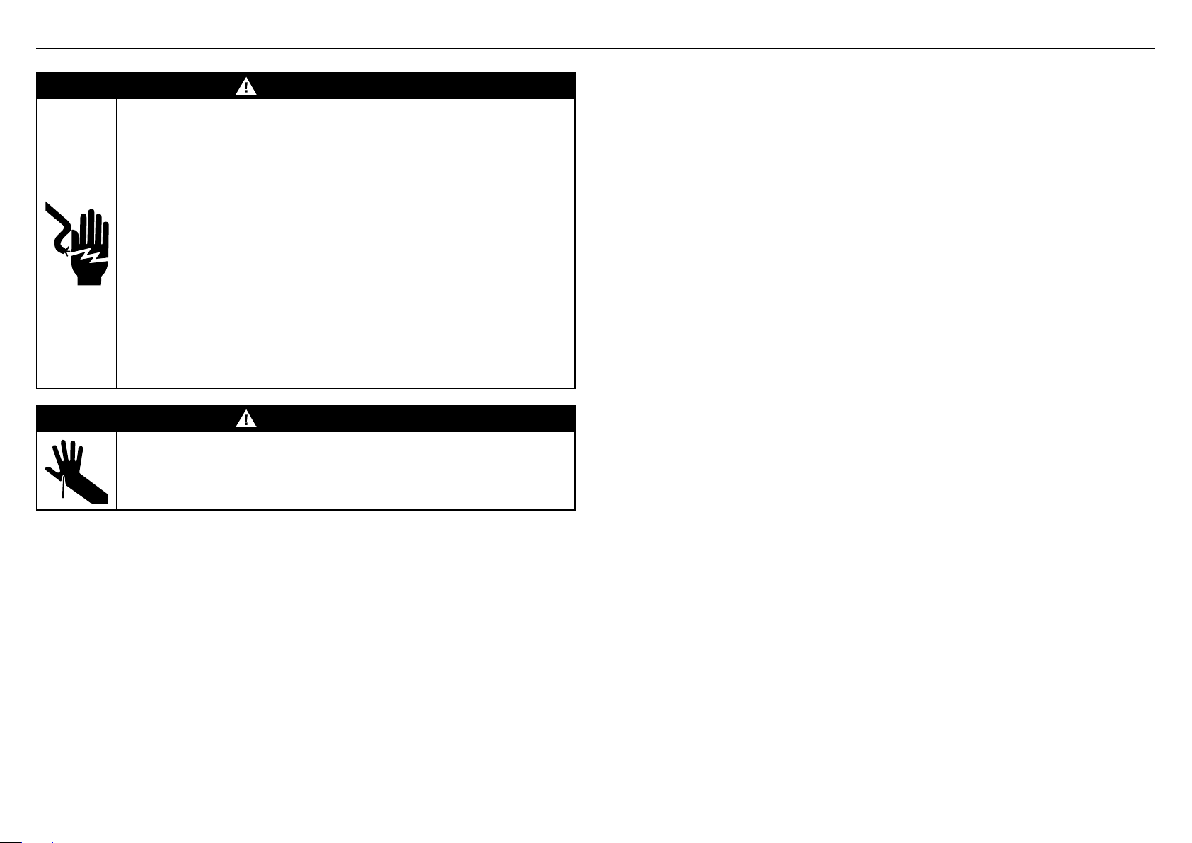
WARNING!
Electrical Shock Hazard
Before installing the dishwasher, remove the house fuse or open the
circuitbreaker.
Ensure that a qualified electrician or service representative has checked
ifthe appliance is properly grounded.
Improper connection of equipment-grounding conductor can result to
riskof electric shock.
Do not modify the power supply plug provided with the appliance—if it will
not fit the outlet, have a proper outlet installed by a qualified electrician.
Do not use an extension cord, adapter plug or multiple outlet box.
Ensure the dishwasher is completely enclosed at the time of installation
toreduce the risk of electrical shock, fire, or personal injury.
Ensure the dishwasher is disconnected from the power supply before
fittingthe front panels.
Ensure components such as panel bracket and any custom metal
component (eg handle) that extends past the rubber seal, are electrically
grounded after installing the front panels.
Failure to follow these advice may result in electrical shock or death.
WARNING!
Cut Hazard
Take care—panel edges are sharp.
Failure to use caution could result in injury or cuts.
IMPORTANT SAFETYGUIDE
z
This dishwasher is manufactured for indoor use only.
z
Ensure to follow safety and the warnings to prevent electrical shock, injury or fire.
z
Ensure to remove all packaging materials supplied with the dishwasher.
z
This dishdrawer is intended for connection to the hot-water supply.
z
The dishwasher MUST be installed to allow for future removal from the enclosure if
service is required.
z
Installation of this dishwasher requires basic mechanical and electricalskills.
z
Installation must comply with your local building, electricity, and plumbing regulations.
z
It is the responsibility of the plumber and electrician to ensure that each installation
complies with all Codesand Regulations.
z
The switched power outlet must be located outside the dishwasher cavity to allow easy
access after installation. Take care when installing or removing the appliance to avoid
possible damage to the power supply cord andhoses.
z
If the dishwasher is to be relocated from one installation to another it must bekept
upright to avoid damage from water spillage.
z
Make sure only new hoses are used for connection (supplied with the dishwasher).
Oldhoses should not be reused.
z
Failure to install the dishwasher correctly could invalidate any warranty or liability claims.
z
Fitting integrated front panels requires access to electrical service areas. This work must
be performed and certified by a qualified electrical service technician.
z
Ensure the appliance is not plugged in when fitting custom panels.
z
Failure to install the custom panels correctly could invalidate anywarranty or
liabilityclaims.
z
At the completion of the dishwasher installation, the Installer mustperform
theFinalChecklist.
GROUNDING
z
This appliance must be grounded. In the event of a malfunction or breakdown, grounding
will reduce the risk of electric shock by providing a path of least resistance for
electriccurrent.
z
Thisappliance is equipped with a cord having an equipment-grounding conductor and a
grounding plug. The plug must be plugged into an appropriate outlet that is installed
and grounded in accordance with all local codes and ordinances.
z
If the dishwasher is installed as a permanently connected appliance:
This appliance must be connected to a grounded metal, permanentwiring system,
or anequipment-grounding conductor must be run with the circuit conductors and
connected to the equipment-grounding terminal or lead on theappliance.
3
Page 6
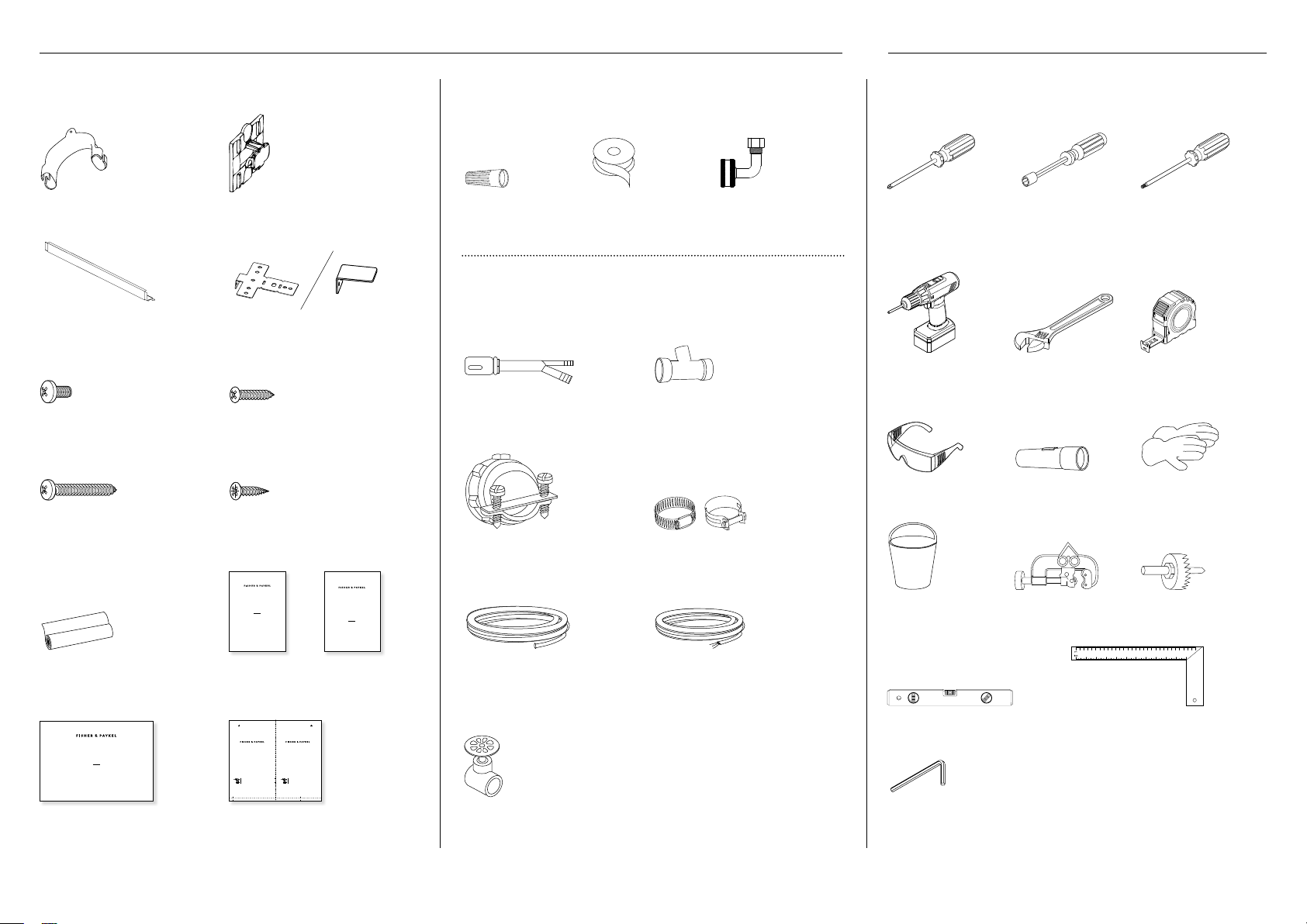
2COMPONENTS 3TOOLS
Supplied parts
Drain hose support
(1)
Infill bracket
(1)
Ø3.5 x 1/2” (12mm) screws
(4)
Ø3.9 x 1 1/2” (38mm) screws
(4)
Plastic slider
(1)
Mounting brackets for wood
countertop or side cabinets (2)
Ø4 x 1” (25mm) screws
(4)
Ø3.9 x 1/2” (13mm) screws
(4)
Required parts
UL-listed wire nuts
(3)
Thread seal tape
(1)
Components for new installation only
(available in hardware stores)
Air gap for drain hose
(use only if required)
3/4”(16mm) Strain relief for
electrical connection
Waste tee for house plumbing
(use only if required)
Screw-type hose clamps
3/4”(19mm)
Elbow 90° (1)
Required tools
Phillips-head
screwdriver
Powered drill Adjustable wrench 6”
Safety glasses Flashlight Gloves
Nutdriver
1/4” (6.35mm) and 5/16”
(7.94mm)
(152.4mm)
Torque driver T25
Measuring tape
Moisture protection tape for
cabinetry (1)
DISHWASHER
DW24U6I1 & DW24U2I1 models
INSTALLATION GUIDE
US CA
Installation guide
(1)
4
DISHWASHER
DW24U2I and DW24U6I
models
USER GUIDE
US CA
User guide
(1)
DOOR PANEL TEMPLATE GABARIT DE PANNEAU DE PORTE
591518B 05.19 591518B 05.19
Centre line
Ligne centrale
Pilot holes
Avant-trous
Utilisez ce gabarit pour percer avec précision les avant-trous destinés à la fixation
de votre panneau de porte encastré.
Déterminez la hauteur de porte appropriée ci-dessous et alignez le gabarit avec la base
de votre panneau de porte. Pour les instructions d’installation complètes, reportez-vous
au Guide d’installation fourni avec votre appareil.
Partie saillante de la porte : 1 5/16 po – 2 1/8 po (34 mm – 54 mm)
Partie saillante de la porte : 2 1/8 po – 2 15/16 po (54 mm – 74 mm)
Door overhang: 1 5/16" – 2 1/8" (34mm – 54mm)
Door overhang: 2 1/8" – 2 15/16" (54mm – 74mm)
Use this template to accurately drill the required pilot holes in your custom door panel.
Establish the appropriate dimension below and align the template with the base of your panel.
For full installation guidance, refer to the Installation Guide supplied with your appliance.
Door panel template
(1)
SERVICE & WARRANTY
SERVICE ET GARANTIE
ΣΈΡΒΙΣ ΚΑΙ ΕΓΓΎΗΣΗ
SERVIZIO E GARANZIA
SERVICE & GARANTIE
HUOLTO JA TAKUU
SERVICE OG GARANTI
保修和维修
服務和保修
Service &
Warranty (1)
Hot water line with ferrule and
compression nut – min 3/8”
(9.5mm) copper tubing or flexible
braided hose
Hand shut-off valve (recommended)
ØElectrical cable or Power cord
kit (5’ 4” long) or (7’ 9” long)
depending on your installation
Bucket – for flushing
Tubing cutter Hole saw set
the line
Level Carpenter’s square
Allen key 1/4” (6mm)
Page 7
4TECHNICAL DATA
Technical data
Check the electrical data on the rating label (located on the left-hand side of the dishwasher’s stainless steel inner door).
If the data on the rating label are different to the specification below, consider the data as correct.
DW24U2I1 models DW24U6I1 models
Capacity 12 place settings 14 place settings
Mains water pressure 0.03-1 MPa (= 0.3-10 bar) 0.03-1 MPa (= 0.3-10 bar)
Power voltage 120V (60 Hz) 120V (60 Hz)
Maximum current intensity 8.9 A 8.9 A
Total absorbed power 1050 W 1050 W
5BEFORE INSTALLATION
Unpacking and handling
z
Check packaging and dishwasher for signs of transport
damage. Do not install if the dishwasher is damaged.
Contact the dealer where you purchased the dishwasher.
z
We recommend to recycle some of the packaging. Check
the symbols and labels toensureif recycling is possible.
z
Always be careful with the hoses and power cord at the
back of the dishwasher. Ensurethey are not squashed,
kinked or cut to prevent damage and malfunction.
Connections and services
z
Do not use extension cords or multi-outlet power boards
to connect the dishwasher tothepower supply.
z
Do not connect the dishwasher to a water system where
the temperature exceeds 140°F (60°C), or where there is
no temperature control, eg wetback system, unless the
system isfitted with a suitable tempering valve.
z
Do not connect the dishwasher to an undersink highpressure ‘push-through’ type hot water system to prevent
damage to the system.
Accessory door panels installation options
z
ADA Door panel (82085)
z
Standard (Tall) door panel with infill bracket (82084)
Refer to Quick installation guide (595703A) for more
information
C
B
A
If opting for the standard
install method, an infill
bracket must be fitted.
Anti-flood protection
This dishwasher has anti-flood protection
which will stop the water flowing in the event
ofaleak within the machine.
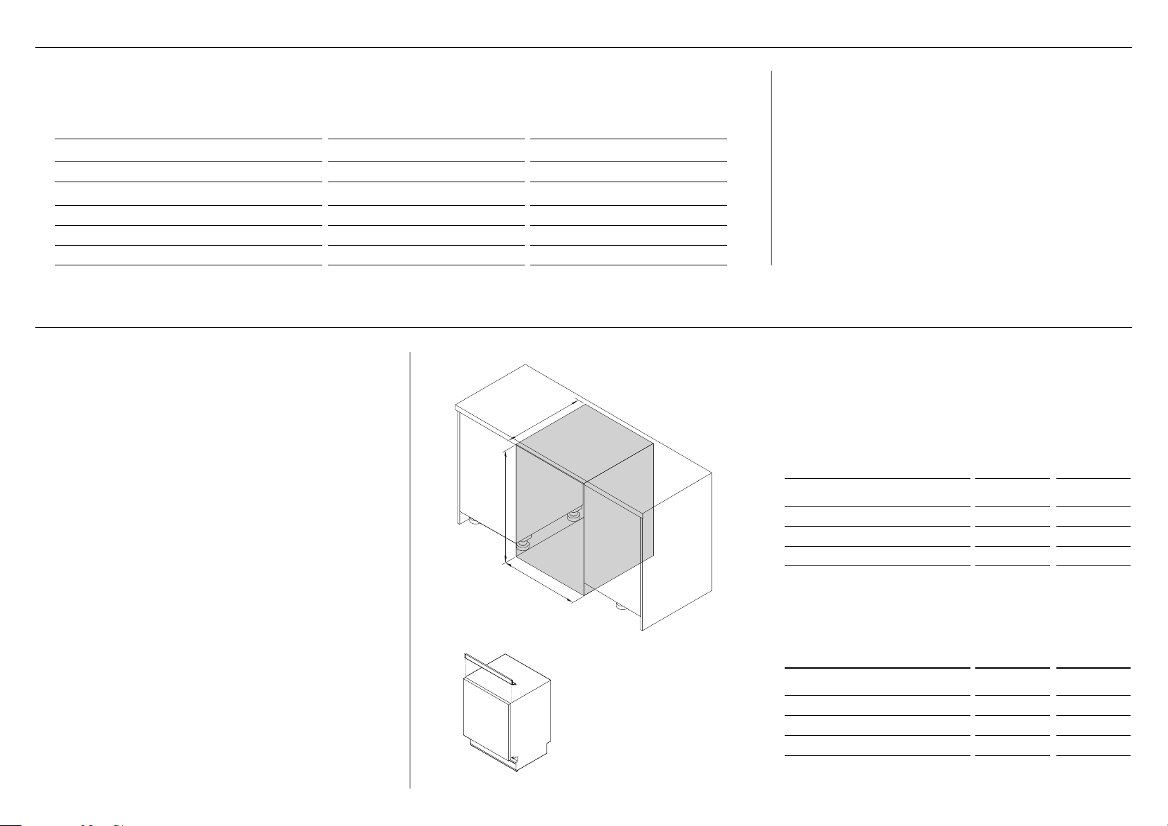
Identify install method
Based on your cabinetry dimensions, identify the
appropriate installation method. For further cabinetry
dimensions, refer to pages 8-.9
Standard install
CABINETRY DIMENSIONS in mm
Inside width of cavity 24 610
A
Inside height of cavity* 34 - 36 1/2 864- 927
B
Inside depth of cavity** 24 610
C
* depending on adjustment of levelling feet
** incl. 3/4” (19mm) panels
ADA install
CABINETRY DIMENSIONS in mm
Inside width of cavity 24 610
A
Inside height of cavity* 32 3/8 - 34 5/8 822 - 880
B
Inside depth of cavity** 24 610
C
* depending on adjustment of levelling feet
** incl. 3/4” (19mm) panels
5
Page 8
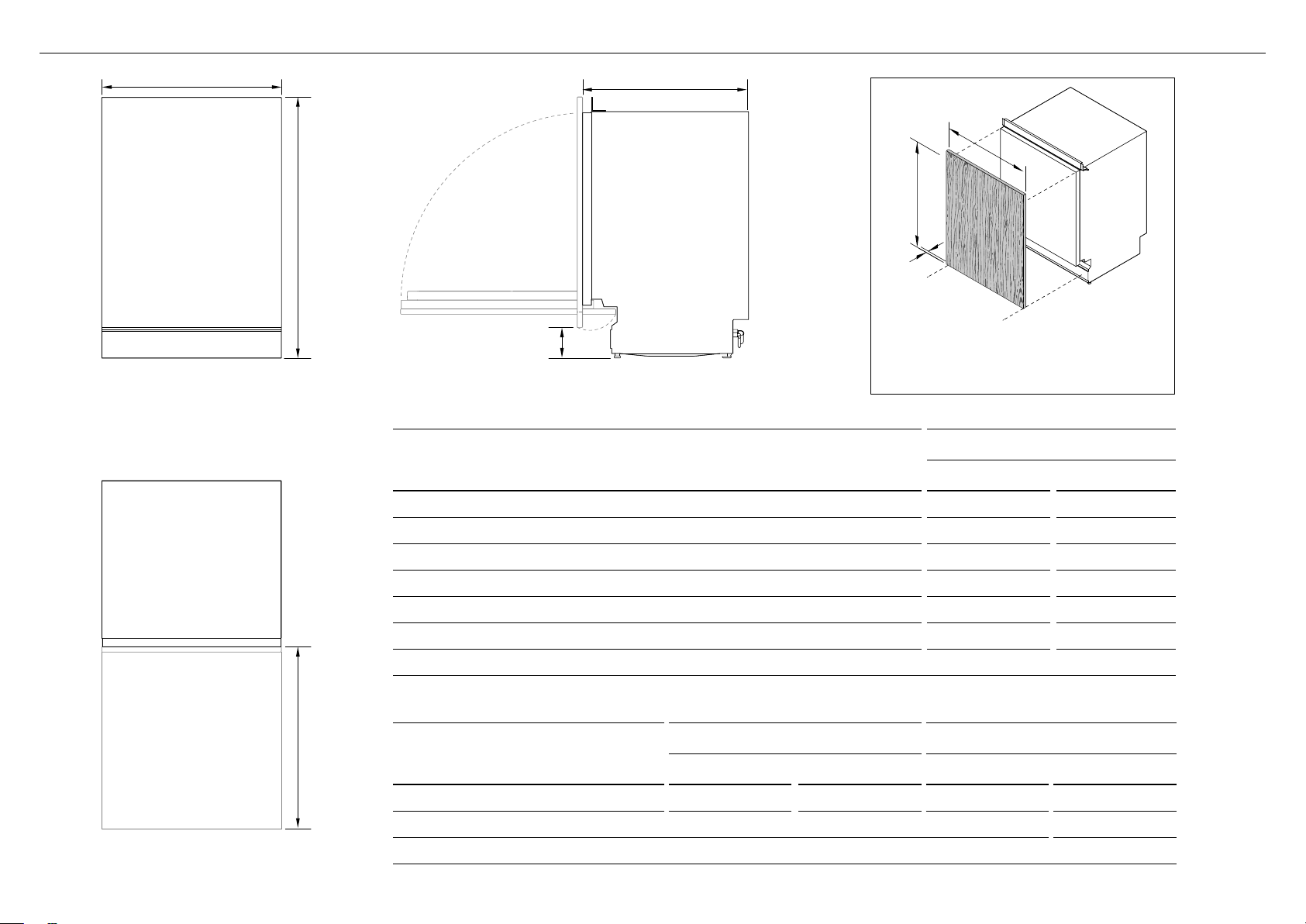
NOT TO SCALE
6APPLIANCE DIMENSIONS: STANDARD
B C
A
D
G
F
H
FRONT
PLAN
E
PROFILE
APPLIANCE DIMENSIONS
Overall height of appliance* 34 - 36 1/2 864–927
A
Overall width of appliance (excl. side seals) 23 3/4 603
B
Overall depth of appliance (excl. custom panel & handle) 22 3/4 579
C
Height from floor to bottom of:
d
z
custom door panel 4–8 100–200
z
accessory door panel 4 – 6 3/8 100–160
Depth of open door (measured from front of chassis) (excl. custom panel) 23 7/8 606
e
* depending on adjustment of levelling feet
DOOR PANEL DIMENSIONS
Height* 28 1/4 – 30 1/4 717 – 769 29 3/4 756
f
Width* 23 7/16 – 23 13/16 596 – 605 23 7/16 595
g
Depth* 5/8 – 3/4 16–19 3 /4 19
h
CUSTOM PANEL STAINLESS STEEL PANEL
in mm in mm
DW24U6I1/DW24U2I1 models
in mm
6
* depending on cabinetry dimensions
Page 9

NOT TO SCALE
6APPLIANCE DIMENSIONS: ADA
B
FRONT
A
C
G
F
H
D
PROFILE
APPLIANCE DIMENSIONS
Overall height of appliance* 32 5/16 - 34 5/8 821–880
A
Overall width of appliance (excl. side seals) 23 3/4 603
B
Overall depth of appliance (excl. custom panel & handle) 22 3/4 579
C
Height from floor to bottom of:
d
z
custom door panel 4–8 100–200
z
accessory door panel 4 – 6 3/8 100–160
DW24U6I1/DW24U2I1 models
in mm
PLAN
E
Depth of open door (measured from front of chassis) (excl. custom panel) 23 7/8 606
e
* depending on adjustment of levelling feet
DOOR PANEL DIMENSIONS
Height* 26 1/2 – 28 1/4 674 – 717 28 1/8 714
f
Width* 23 7/16 – 23 13/16 596 – 605 23 7/16 595
g
Depth* 5/8–3/4 16–19 3 /4 19
h
* depending on cabinetry dimensions
CUSTOM PANEL STAINLESS STEEL PANEL
in mm in mm
7
Page 10

I
7CABINETRY DIMENSIONS: STANDARD
J
K
PLAN
DW24U6I1/DW24U2I1 models
CABINETRY DIMENSIONS in mm
Inside width of cavity 24 610
I
Inside height of cavity* min 34
J
Inside depth of cavity (incl. 3/4” (19mm) panels) 24 610
K
* depending on adjustment of levelling feet
CLEARANCE DIMENSIONS in mm
Clearance from corner cupboard 1/2 13
L
Clearance to adjacent cupboard door min. 1/16 2
m
Before installing the standard (tall) door panel, an infill bracket must be attached as a cosmetic
feature to fill the gap between the top of the dishwasher and underside of cabinet top.
max 36 1/2
DW24U6I1/DW24U2I1 models
8
PROFILE
864
927
l m
PLAN
Page 11

I
7CABINETRY DIMENSIONS: ADA
J
K
PLAN
DW24U6I1/DW24U2I1 models
CABINETRY DIMENSIONS in mm
Inside width of cavity 24 610
I
Inside height of cavity* 32 3/8 - 34 5/8 822 - 880
J
Inside depth of cavity (incl. 3/4” (19mm) panels) 24 610
K
* depending on adjustment of levelling feet
DW24U6I1/DW24U2I1 models
CLEARANCE DIMENSIONS in mm
Clearance from corner cupboard 1/2 13
L
Clearance to adjacent cupboard door min. 1/16 2
m
PROFILE
l m
PLAN
9
Page 12

8 ELECTRICAL AND PLUMBING PREPARATION
Select plumbing option
z
Hose connection
z
Copper pipe connection
Refer to ‘Plumbing and Drainage options’ (page 16) for more information.
Left side of
appliance
Supply area dimensions
Final position of dishwasher against wall
SECTION inches mm
A
b
C
B
A
C
24 610
4 15/16 125
2 50
10
Page 13

9 CAVITY PREPARATION
COUNTERTOP
3/8”
(10mm)
Moisture
protection tape
must be applied
Note: if no side partition is
present, a timber bracing can
be constructed for securing to.
WARNING!
Incorrect placement of the hole
will result in damage to hoses.
IMPORTANT!
The power outlet must be located in
a cabinet adjacent to the dishwasher
cavity. 110-120 VAC max. 15 A
Ø 1 1/2”
(38mm)
max. 17 11/16”
(450mm)
Water Connection
Recommended HOT
(Maximum 140°F/60°C).
Supplied hose to suit 3⁄8” (9mm)
male compression fitting.
Water Pressure
Water softener models
Max. 1 MPa (145 psi)
Min. 0.1 MPa (14.5 psi)
Models without water softener
Max. 1 MPa (145 psi)
Min. 0.03 MPa (4.3 psi)
Max 1/4” (5mm)
Max distance
between hole edge
and rear inner face
Max 1/2” (10mm)
Max distance between
hole edge and floor
Service Holes
Can be located either side of dishwasher, close to the rear face and
the floor, as illustrated, for access to the water supply and drain.
z
If the hole is through wood, make sure its edges are smooth
androunded.
z
If the hole is through metal, ensure you fit the supplied Edge
Protector to prevent damage to the power cord.
min. 7 7/8” (200mm)
IMPORTANT!
When connecting drain line to
disposer, check to be sure that
drain plug has been removed.
Dishwasher will not drain if plug
is left in place.
Remove drain plug
11
Page 14

IMPORTANT!
z
The infill bracket is installed as a cosmetic feature to fill the empty space
visible for cabinets with cavity height of 34” or above.
z
Installation of infill bracket is not needed for cabinets with ADA standard.
!0 ATTACH INFILL BRACKET
side wings
1 Remove upper mounting bracket and plastic plugs
z
Open the door.
z
Unscrew the upper mounting bracket from the top
ofthe appliance.
z
Push a small screwdriver downward through the
screwhole from the top of the appliance to remove
the plastic plug.
12
2 Install the infill bracket
z
Remove two screws pre-installed from the
infillbracket.
z
Use the same screws to attach the bracket to the
topof the appliance. Do not tighten fully.
3 Align and adjust appliance in cabinetry
z
Push the appliance into the cabinetry.
Ensuretheinfillbracket do not hit the top of the
cabinet while pushing. (Refer to ‘Align appliance in
cabinetry’ for more details.)
z
Slide the side wings of the bracket outward to cover
the hollow space.
z
Hand tighten the two screws.
Page 15

Stainless Steel door installation
For guidance on fitting a stainless steel door panel,
refer to installation guide 592201 for details.
IMPORTANT!
z
Ensure the custom door panel has the correct specifications
tofitthe front of thedishwasher.
z
Ensure the back andsides of the panel are completely sealed
with a waterproof vapor barrier (ie polyurethane). The barrier
allows thepanel to withstand moisture (122°F (50°C) @ 80% RH)
andprevent damage during hot and wet environment.
z
Overall weight of custom door panel must be between 8.9–17.6lbs
(4–8kg)
Measure the panel and overhang
Measure the custom panel and check the overhang length
from the base of the door.
!1 CUSTOM DOOR PANEL PREPARATION
Upper overhang detail
(when using an infill bracket)
1 5/16–2 15/16”
(4-74mm)
Lower overhang detail
(all custom panel installations)
[A] DRILL PILOT HOLES USING SUPPLIEDTEMPLATE
Using the supplied Door Panel Template, mark out and drill the required pilot holes
into your custom panel. Ensure pilot holes are 1/16” (2mm) wide and 1/2” (12mm) deep.
DOOR PANEL TEMPLATE GABARIT DE PANNEAU DE PORTE
591518B 05.19 591518B 05.19
Centre line
Ligne centrale
Pilot holes
Use this template to accurately drill the required pilot holes in your custom door panel.
Establish the appropriate dimension below and align the template with the base of your panel.
For full installation guidance, refer to the Installation Guide supplied with your appliance.
Door overhang: 1 5/16" – 2 1/8" (34mm – 54mm)
Door overhang: 2 1/8" – 2 15/16" (54mm – 74mm)
Avant-trous
Utilisez ce gabarit pour percer avec précision les avant-trous destinés à la fixation
de votre panneau de porte encastré.
Déterminez la hauteur de porte appropriée ci-dessous et alignez le gabarit avec la base
de votre panneau de porte. Pour les instructions d’installation complètes, reportez-vous
au Guide d’installation fourni avec votre appareil.
Partie saillante de la porte : 1 5/16 po – 2 1/8 po (34 mm – 54 mm)
Partie saillante de la porte : 2 1/8 po – 2 15/16 po (54 mm – 74 mm)
[B] MANUALLY MARK AND DRILL PILOT HOLES
If the template is not available, mark the pilot holes manually on your custom panel based on
measurements in the below table. Ensure pilot holes are 1/16” (2mm) wide and 1/2” (12mm) deep.
If overhang is between 1 5/16” (34mm) and 2 1/8” (54mm):
PANEL A MEASUREMENTS in (mm)
Base of panel to lower bracket hole
A
Base of panel to upper bracket hole 4 7/8 (124)
B
Base of panel to handle holes 18 9/16 (472)
C
Centre line to handle holes 9 1/4 (235)
d
If overhang is between 2 1/8” (54mm) and 2 15/16” (74mm):
4 1/16 (103)
PANEL B MEASUREMENTS in (mm)
Base of panel to lower bracket hole
A
Base of panel to upper bracket hole 5 11/16 (144)
B
Base of panel to handle holes 19 3/8 (492)
C
Centre line to handle holes 9 1/4 (235)
d
Note: measurements are to center of holes.
4 13/16 (123)
D D
a
C
B
13
Page 16

Top screw detail
(between panel and screw head)
3mm
!2ATTACHING CUSTOM DOOR PANEL
1 Fix slider bracket and screws to custom panel
Insert Ø3.9 x 1/2” (13mm) screws through the top two
pilot holes. Fix the slider bracket to the panel through
the lower pilot holes.
Increase
Decrease
4 Balance the door
Check the door balance by opening and closing
the door. If the door drops when released,
increase the tension. If the door rises when
released, decrease the tension.
14
2 Hang custom panel onto the door
Close the door of the dishwasher and align the screws
and the bracket on the custom panel to the front of the
dishwasher door.
5 Secure the custom panel
Open the door and remove the
four screws and replace with
Ø3.9 x 1 1/2” (38mm) screws to
fix the panel into place.
3 Adust the placement of the custom panel
Slide the custom panel up or down to position it in the
desired location.
Screw locations
(repeat on both side of appliance)
Page 17

!3LEVEL DISHWASHER
IMPORTANT!
Ensure the appliance is leveled for proper dish rack, wash performance and door operation.
To verify dishwasher is leveled, open and close the door and pull the dish racks half way out.
Thedoorshould fit in the tub opening without hitting the sides. Iftheracks roll on their own, or
the door hits the side of tub, re-level.
0-1/4
(0-6.4mm)
1 Remove toe kick and mounting plate
To access the rear leg adjustment pin, you will need to remove the four screws
holding the toe kick and mounting plate. Set screws aside for re-installation.
!4ALIGN APPLIANCE IN CABINETRY
IMPORTANT!
z
Ensure top of door is aligned flush with surrounding cabinetry.
z
Use floor protection before sliding the appliance into the cabinetry.
Remove the protection once the appliance is positioned in
thecabinetry.
As you push the appliance in, pull through hoses and cord, ensure
they don’t get kinked or twisted.
Note: If using an infill bracket for cabinets with cavity height of 35.5”
or above, refer to ‘Attach infill bracket’ (page 10) for moredetails.
2 Adjust leg height
Adjust the rear foot via the back leg adjustment pin using an Allen Key.
The front feet can be adjusted using an adjustable wrench.
Center appliance
floor protection
15
Page 18

!5 ELECTRICAL CONNECTION
IMPORTANT!
z
Ensure the power cord and connections comply with the National Electrical Code, Section 422 and/or local codes
and ordinances. Maximum power cord length is 6 feet. A Power Cord Kit is available for purchase from an authorized
Fisher&Paykel appliancesdealer.
z
Check the house wiring. If it is not 2-wire with ground, a ground must be provided by the installer.
If the house wiring is aluminum, use UL-Listed anti-oxidant compound and aluminum-to-copper connectors.
White wire UL listed wire nutsBlack wire
Power cord/
house wiring
1 Remove the junction box cover
Unclip and remove the junction box cover to access
theappliance electronics. Do not remove the screw
holding the junction box bracket in place.
16
(grounded)
Grounding screwGreen wire
Strain relief
2 Connect wires
Install the strain relief into the junction box bracket,
andsecure the house wiring or the power cord and
tighten. Thread the wires through the hole in the junction
box bracket and connect the incoming ground to green,
white to white and black to black.
3 Refit the junction box cover
Refit the junction box cover ensuring no wires are
pinched beneath the cover. Ensure the power cord
isrouted under the appliance.
Page 19

!6 HARD PLUMBING
IMPORTANT!
Ensure to flush the water line into a bucket before connecting to the water inlet valve.
Prepare water supply connection Connect hot water line to inlet valve
inlet valve
elbow (90°)
inlet valve
braided hose
gasket
1 Connect an elbow (90°) to the water inlet valve.
z
Ensure a rubber gasket is placed between the threads of the elbow
and water supply valve. Do not overtighten the elbow.
z
Ensure the end of the elbow is pointing to the rear of the dishwasher.
hand shut-off valve
hot water line
2 Insert the hot water line (copper pipe or flexible braided hose) through
the water supply hole from the side of the cabinetry. (Refer to ‘Cavity
preparation, page 9 for more details).
z
Be careful not to damage the water line while inserting through the hole.
3 Install a hand shut-off valve to the water line in a location that is easily
accessible in the adjacent cabinetry (eg under the sink).
elbow (90°)
1 If using a flexible braided hose:
Screw the nut of the hose to the thread of the elbow.
Tighten with an adjustable wrench.
inlet valve
copper pipe
elbow (90°)
elbow (90°)
2 If using a a copper pipe:
Slide the compression nut and ferrule towards the end of the pipe.
Insert the end of the pipe into the elbow and screw the compression
nut to the thread of the elbow.
17
Page 20

!7 PLUMBING AND DRAINAGE OPTIONS
Dishwasher using drain hose joiner onto sink trap/waste teeDishwasher and Ø 38mm Standpipe
max.
4 3/4”
(120mm)
(750-883mm)
29 1/2”-34 3/4”
IMPORTANT!
Ensure that drain connection complies
withlocal plumbing regulations.
Screw drain hose support to back wall at
correct height. If space is limited for fixing,
push hose through drain hose support to
required height.
Ø1 1/2”
(38mm)
min. R 8”
(200mm)
29 1/2–34 3/4” (750-883mm)
min. 19 11/16” (500mm)
(750-883mm)
29 1/2”-34 3/4”
IMPORTANT!
Ensure that drain connection complies
withlocal plumbing regulations.
Screw drain hose support to back wall at
correct height. If space is limited for fixing,
push hose through drain hose support to
required height.
29 1/2–34 3/4” (750-883mm)
min. 19 11/16” (500mm)
IMPORTANT!
Ensure that drain hose is installed as close to the underside of the benchtop
as possible. This will ensure no waste re-enters the drain hose in the event of
poor flow or a blockage in the plumbing.
Ensure the drain hose does not extend into water retained in the trap.
An air gap is required to prevent waste water from siphoning back into the tub.
18
Page 21

!8TOE KICK INSTALLATION
IMPORTANT!
Ensure toe kick does not protrude more than3 9/16" (90mm) out from the dishwasher to ensure that the visibility of the floor light isnotobstructed.
Toekick excess
(to be cut back)
Door panel
Toekick
1 Refit toekick mounting plate and panel.
Refit the toekick and mounting plate panels that were removed earlier.
If desired, a custom continuous toekick panel can be installed.
3 Align and prepare continuous toekick panel.
Align the toekick to desired position and mark out the point in which the toekick
meets the base of the door panel. Cutback excess.
2 Check door overhang and swing range.
Door overhang and swing range is relative to height and depth of toekick panel.
Cut back excess panel to ensure continuous, seamless integration.
4 Fit continuous toekick panel to the surrounding cabinetry.
19
Page 22

!9 SECURE THE APPLIANCE
[A] FIX THE PRODUCT
TO ADJACENT CABINETRY
[B] FIX THE APPLIANCE
TO BENCHTOP ABOVE
Using two Ø4 x 25mm screws, secure the product to the adjacent cabinetry
through the brackets located on each side of the product chassis.
20
Using two Ø4 x 25mm screws, secure the appliance to the benchtop above
through the brackets located at the top of the appliance chassis.
IMPORTANT!
This installation method is not applicable if an infill bracket has been installed.
If the infill bracket is not used, we recommend to fix the appliance to the
adjacent cabinetry or above the benchtop.
Page 23

@0 CONNECT INLET HOSE TO HOT WATER
Plumbing—Water inlet connection
IMPORTANT!
z
Ensure the appliance is connected to the water main using the supplied new water inlet hose. Do not use old hoses.
z
Do not shorten the inlet hose.
1 Follow the water connection requirements.
z
We recommend a hot water connection.
z
The incoming water temperature should not exceed 140oF.
2 Hot water pressure:
z
Take note of the permitted water pressure extremes.
z
Lowest: 5psi
z
Where pressure is 5psi, contact a qualified plumber.
z
Highest: 140psi
z
Install a pressure reduction valve if pressure is above 140psi. Contact a qualified plumber.
3 Connect the water inlet hose to an accessible water tap with a 3/4” BSP connector.
Ensure that there is no kink in the inlet hose that could restrict the flow of water.
A 90o bend requires a minimum height of 200mm for a kink-free curve.
z
Ensure incoming water is clear. If the water pipes have not been used for a long period of time,
let the water run to make sure it is clear with no impurities. Not doing so may result in the water
inlet hose getting blocked and damaging the appliance.
z
If required, use a filter insert to filter out deposits from the piping. The filter insert is
available from your Fisher&Paykel trained and supported service technician or Customer Care.
4 Tighten the hose coupling a further half turn after seal contact.
5 Check that the connection does not leak.
Ensure the supplied
1 2
rubber washer is fitted
inside the coupling.
Tighten coupling
with spanner.
@1 CONNECT TO POWER
Electrical connection
z
Do not connect the dishwasher to the electrical supply while installation is on-going. Ensure all domestic wiring is properly earthed.
z
Check the rating label (located on the left-hand side of the dishwasher’s stainless steel inner door) and ensure that the voltage and frequency values
for the current in the house correspond to those on the rating label.
z
Insert the plug into a properly earthed power outlet that has a disconnection switch.
IMPORTANT!
z
The earthing of the appliance is a safety requirement mandated by law.
z
If the power cord is not long enough to reach the outlet or the outlet to which the appliance must be connected is not appropriate for the plug, the entire
dishwasher power cord must be replaced. This should only be done by a Fisher&Paykel trained and supported service technician. Do not modify or cut the plug.
Do not use an adaptor, extension cord, or multi-outlet power board to connect the dishwasher to the power supply, as these could cause overheating and
createa fire hazard.
z
The outlet into which the dishwasher is plugged must remain easily accessible (eg in an adjacent cabinet) even when the appliance is installed.
This is to ensure that the dishwasher can be disconnected from the power supply for safe cleaning and maintenance.
21
Page 24

@2 TROUBLESHOOTING
Excessive water remaining above the filter plate, after the rinse cycle (this can be displayed as A20 fault)
z
Check for a kinked drain hose, blocked waste connection, highloop not properly installed,
drain hose not routed correctly or spray arms not in place.
No water supply (this is displayed as A10 fault)
z
Check water is connected and turned on.
The dishwasher is beeping continuously
z
There is a fault.
z
See section ‘How to attend to a fault’ in the User Guide for further information.
Water around water supply and drainage connections
z
Check connections, existing plumbing and hoses for leaks.
z
Check rubber washer and hose clamp are correctly fitted.
If appliance is tipping
z
The appliance is not secure under the benchtop.
z
Ensure the appliance is level and placed between cabinetry.
z
Adjust the feet so that the dishwasher sits securely under the benchtop.
If front panel is misaligned
z
Check and re-level appliance.
z
Check the cabinetry is square.
z
Check and adjust the front panel alignment if necessary.
Door doesn’t close properly
z
Ensure nothing is obstructing the door from closing properly.
z
Check that the customized panel is a suitable length to fully close and that there is enough clearance for the door,
so that the door’s movement is not obstructed by the floor or surrounding cabinetry.
If a problem occurs, see ‘Troubleshooting’ page of the User guide.
If after checking these points you still need assistance, refer to the Service & Warranty book for warranty details
and your nearest Fisher&Paykel trained and supported service technician, or contact us through our website fisherpaykel.com.
22
Page 25

TO BE COMPLETED BY THE INSTALLER
@3 FINAL CHECKLIST
F Check all parts are installed.
F Ensure that all panels and parts thereof are secure and final electrical tests have been
conducted in accordance with local electrical regulations.
F Check that the dishwasher is level. If necessary, adjust the levelling feet slightly.
To ensure optimum performance, the dishwasher should not be inclined more than 1o.
Check with a spirit level.
F Ensure inlet hose to water supply has supplied rubber washer fitted, and that it’s
tightened a further half turn after seal contact.
F Ensure any knockouts or plugs in drain connection have been drilled out and drain
connection has been made.
F The drain hose joiner must not support the weight of excess hose material.
Keepdrain hose as fully extended as possible to prevent sagging.
Any excess length of drain hose should be kept on the dishwasher side of thehighloop.
F If connecting the drain hose to the sink trap, ensure the Highloop is a minimum
5 15/16" (150mm) higher than the drain hose joiner.
F Ensure any packaging or tape securing the racks is removed from the dishwasher.
F Ensure appliance is level and opens and closes freely. The door must be free to fully
closewithout being obstructed by adjoining cabinetry or the floor.
F Check that the door opens and closes freely without resistance to adjacent cabinetry.
F Check that the electrical outlet is accessible and located in an adjacent cupboard.
F Check the operation of the dishwasher:
1 Open door to turn dishwasher on.
2 Select the Rinse programme.
3 Press > to start the Rinse programme. Can you hear the dishwasher filling?
4 When the Rinse programme is over (approximately 20 minutes), check that the
waterhasdrained.
F If a fault code appears, see the ‘Fault codes’ section of the User guide for advice.
F Ensure that you leave the instruction guide with the customer.
Complete and keep for safe reference:
Model
Serial No.
Purchase Date
Purchaser
Dealer Address
Installer’s Name
Installer’s Signature
Installation Company
Installation Date
23
Page 26

FISHERPAYKEL.COM
© Fisher&Paykel Appliances 2020 All rights reserved.
The product specifications in this booklet apply to the specific products
and models described at the date of issue. Under our policy of continuous
product improvement, these specifications may change at any time. You
should therefore check with your Dealer to ensure this booklet correctly
describes the product currently available.
US CA
591955C/012050166C02.20
 Loading...