

Fisher & Paykel DD603-88269, DD603-88270, DD603-88445-B, DD603FC-88449, DD603FC-88449-B Installation Guide
...
part number526607 N
Drawer
INSTALLATION INSTRUCTIONS
(NOTE:FOR INTEGRATEDPANELPREPARATIONINSTRUCTIONSREFERTOSUPPLIEDSHEET)
05/2005
(page1 ot 12)
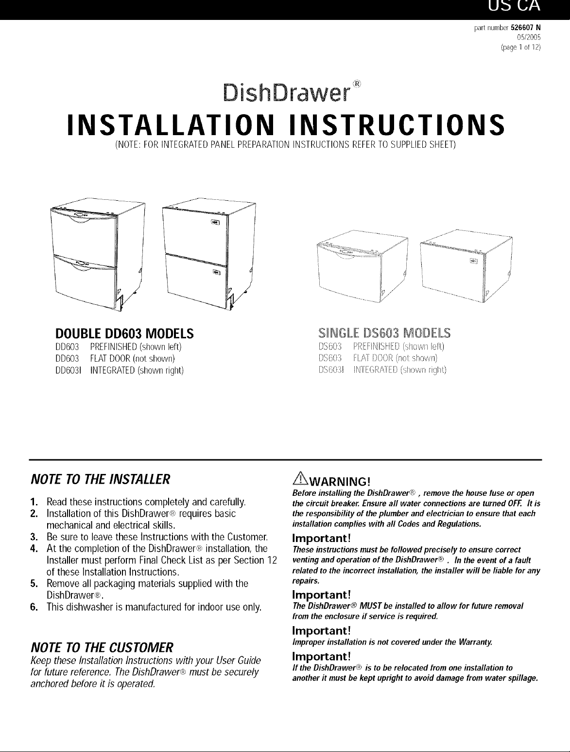
DOUBLEDDC03 MODELS
DD603 PREFINISHED(shown left)
DD603 FLATDOOR(not shown)
DD6031 INTEGRATED(shown right)
NOTE TOTHEINSTALLER
1. Readthese instructions completely and carefully.
2. Installation of this DishDrawer® requires basic
mechanical and electrical skills.
3. Be sure to leave these Instructions with the Customer.
4. At the completion of the DishDrawer® installation, the
Installer must perform Final Check List as per Section 12
of these Installation Instructions.
5. Remove all packaging materials supplied with the
DishDrawer®.
6. This dishwasher is manufactured for indoor use only.
NOTE TOTHECUSTOMER
Keep these Installation Instructions with your User Guide
for future reference, TheDishDrawer® must be securely
anchored before it is operated,
S_NGLE#$603 MO#ELS
I}S(O;_ PI_tttINI',<Ut[}(',_h>v/l_k.#t)
DS603 FLAFDOOROsotshown)
DS6031 INIEGRAIED (sh>wl_light)
i_XWARNING!
Before installingthe DishDrawer® , remove thehouse fuseor open
the circuit breaker.Ensure all water connectionsare turnedOFF. It is
the responsibilityof theplumber and electricianto ensurethat each
installationcomplieswith all CodesandRegulations.
Important!
Theseinstructionsmustbe followed precisely toensure correct
venting andoperation ofthe DishDrawer@. In the event ofa fault
related tothe incorrectinstallation, theinstaller will be liable for any
repairs.
Important!
TheDishDrawer® MUST be installed toallow for futureremoval
fromthe enclosure if serviceis required.
Important!
Improperinstallationis not covered underthe Warranty.
Important!
If the DishDrawer® is to be relocated fromone installationto
anotherit mustbe keptuprightto avoid damagefrom water spillage.
,,- BEFOREYOUSTART- DOUBLE& S/NG£E MODELS
|_ft_k"]!,_lP.,P.,ill.'ll]
r
DOUBLEMODELS
F
%NGLEMODELS
DishDrawer ®
E_.... : ......... __ _ ...........
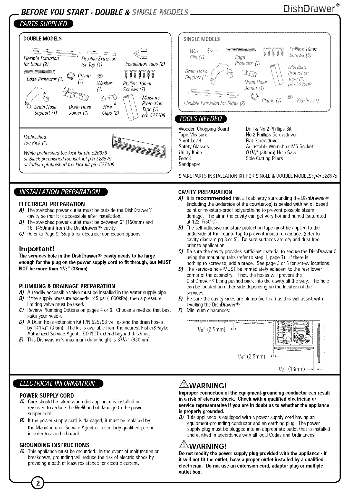
FlexibleExtrusion FlexibleExtrusion
forSides (2) for Top(7)
EdgeProtector (7)
Clamp
(7) Washer
@)
Installation Tabs(2)
Phillips 76mm
Screws (7)
Moisture
Drain Hose DrainHose Wire
Support (7) Joiner (7) Clips(2)
Protection
Tape(1)
p/n 527208
ToeKick (I)
Prefinished
Whiteprefinishedtoe kick kit pin 526678
or Blackprefinished toe kickkitpin 526679
or Iridiumprefinished toekick kit pin 527109
• J
lllVk_lP.fl l,.lll [llArl ,.Itlll ,.i,.It!,.lll[lllv|
ELECTRICALPREPARATION
,4) Theswitched power outlet mustbe outsidethe DishDrawer®
cavity so that it is accessibleafter installation,
B) Theswitched power outlet must be between 6" (150mm)and
18" (450mm)from the DishDrawer® cavity.
¢) Referto Page9, Step5for electricalconnectionoptions,
Important!
The services hole in the DishDrawer® cavityneedsto be large
enoughfor the plugon the power supply cordto fit through,but MUST
NOTbe morethan 11/{' (38ram).
PLUMBING & DRAINAGE PREPARATION
,4) A readilyaccessiblevalve must be installed in the water supply pipe.
B) If the supplypressureexceeds145psi (lO00kPa),then apressure
limiting valvemust be used,
C) Review PlumbingOptionson pages4 or6. Chooseamethodthat best
suitsyour needs,
D) A DrainHoseextension KitP/N525798 will extendthe drainhoses
by 1413/4"(3,6m), Thekit is availablefrom the nearestFisher&Paykel
AuthorizedServiceAgent, DONOTextend beyondthis limit,
E) This Dishwasher'smaximumdrain heightis 37//2" (950mm).
iMm <::' !!!!!!!!!!!!!!!!I_=_'_=_'"_'"_"_";'Phillips 1ram
[tolllo_ (1)
L}_aklllos_
Pm ction
Iq_x%I Exuz s_o,_Ic>_Skl s (?)
I[eIe]!._r#lIlln]llnJ
Wooden Chopping Board
Tape Measure
Spirit Level
Safety Glasses
Utility Knife
Pencil
Sandpaper
SPAREPARTS INSTALLATION KIT FORSINGLE& DOUBLE MODELS: pin 526676
CAVITY PREPARATION
,4) It is recommended that all cabinetry surroundingthe DishDrawer®
(includingthe undersideof the countertop)is sealedwith anoil based
paintor moisture-proofpolyurethaneto prevent possiblesteam
damage, Theair in the cavity can get very hot andhumid(saturated
at 122°F/50°C)
B) Theself-adhesivemoisture protection tape must beappliedto the
undersideof the countertopto preventmoisture damage,(referto
cavity diagram pg 3or 5), Besure surfacesaredry and dust-free
prior to application.
C) Be surethe cavity providessufficient materialto securetheDishDrawer®
using the mountingtabs (referto step 1, page7). Ifthere is
nothing to screw to, add a brace. Seepage3 or 5 for screw locations,
D) The servicesholeMUST be immediatelyadjacent to the rearlower
cornerof the cabinetry, If not, the hoseswill preventthe
DishDrawer® being pushedback into the cavityallthe way, Thehole
can belocated oneither side dependingon the location of the
services.
E) Be surethe cavity sidesare plumb (vertical)as this will assistwith
levellingthe DishDrawer®,
F) Minimum clearances:
Vs" (2,5mm)LIL
Drill& No.2Phillips Bit
No,2Phillips Screwdriver
FlatScrewdriver
AdjustableWrenchor M5 Socket
011/2" (38mm)HoleSaw
SideCutting Pliers
e___lV.,'[_Jltl[_f|llVl,fl]tlA_V.,ll[IAw
POWER SUPPLY CORD
,4) Care should be taken when the appliance is installed or
removed to reduce the likelihood of damage to the power
supply cord,
B) If the power supply cord is damaged, it must be replaced by
the Manufacturer, Service Agent or a similarly qualified person
in order to avoid a hazard,
GROUNDING INSTRUCTIONS
,4) Thisappliancemust begrounded. Inthe event of malfunctionor
breakdown,groundingwill reducethe risk of electric shock by
providinga pathof leastresistancefor electriccurrent.
1/s" (2,5mm)
V2" (13mm)
Z_WARNING!
Improperconnectionof the equipment-groundingconductorcan result
in a risk of electric shock. Check with a qualifiedelectricianor
servicerepresentativeif youare indoubtas towhether the appliance
is properlygrounded.
B) Thisapplianceis equippedwith a power supplycord having an
equipment-groundingconductorand an earthingplug, Thepower
supply plug mustbe pluggedinto an appropriateoutlet that is installed
andearthedin accordancewith all local CodesandOrdinances,
Z_WARNING!
Donot modifythe power supplyplugprovidedwith the appliance- if
it will not fit the outlet, havea properoutlet installedby a qualified
electrician. Do notusean extensioncord,adaptorplugor multiple
outletbox.
,._ DOUBLEMODELS
DishDrawer ®
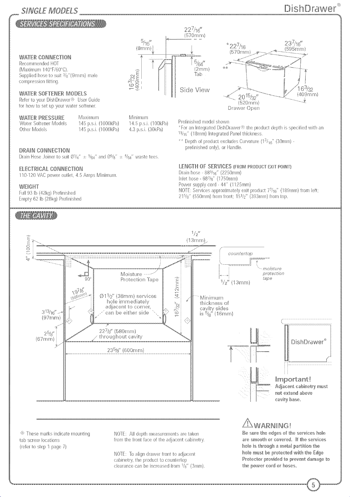
WATER CONNECTION
RecommendedHOT
(Maximum140°F/60°C).
Suppliedhoseto suit 3/8"(9ram)
malecompressionfitting,
WATER SOFTENER MODELS
Referto your DishDrawer®UserGuidefor
how to set upyour water softener.
WATER PRESSURE
WaterSoftenerModels
OtherModels
DRAIN CONNECTION
DrainHoseJoiner to suit 03/4" _+ 5/64", 05/8" + 5/64" and
_31"_+5/64"waste tees,
ELECTRICALCONNECTION
110-120VACpower outlet, 9 Amps Minimum,
LENGTH OF SERVICES(FROMPRODUCTEXITPOINT}
Drainhose- 889/16" (2250mm)
Inlet hose- 687/8"(I 750ram)
Powersupplycord- 44" (l125mm)
NOTE: Services approximately exit product 77/16" (189mm) from left;
215/8" (550ram) from front; 311/4'' (793mm) from top,
Maximum
145p,s.i, (1000kPa)
145p,s,i, (1000kPa)
Minimum
14,5 p,s,i. (lOOkPa) Refinished modelshown
4,3 p.s.i, (30kPa)
Vl#ll _lrJll'd
5/16- I_-
mm/ I,
* Foran IntegratedDishDrawer® the (50-1lOmm)
productdepth is specifiedwith an
11/16" (18mm)IntegratedPanelthickness.
*_ Depthof productexcludes Curvature(13/16,, (30mm)Prefinishedonly,)
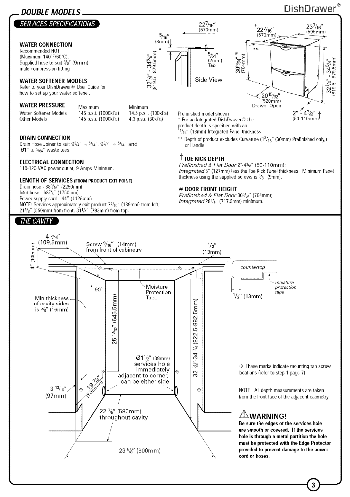
t TOE KICK DEPTH
Prefinished & Flat Door 2"-43/8"(50-110mm);
Integrated 5" (127mm) lessthe ToeKick Panelthickness. Minimum Panel
thicknessusingthe suppliedscrews is 3/8"(gmm).
# DOOR FRONT HEIGHT
Prefinished & Flat Door 305/64" (764mm);
Integrated 281/4'' (717.Smm)minimum.
227/16"
(570mm)
Side View ° __2015/_,,_ _ :
or Handle.
"227/16" 237/16"
(570turn) _
(520rnm) k-"'----_
Drawer Open
2" _ _3/8" _
_Lo
4 5/16"
(109.5mm)
Min thickness
of cavity sides
is 5/8" (16ram)
3 13/16_'/
(97mm)
Screw 9/16" (14mm)
from front of cabinetry
\
. can be either side
i adjacent to corner,
Moisture
Protection
Tape
011/2" (38mm)
services hole
immediately
1/2"
(13mm)
countertop
1/2" (13mm)
Thesemarksindicate mountingtab screw
locations(referto step 1 page 7)
NOTE: All depth measurements are taken
from the front face of the adjacent cabinetry.
22 7/8" (580mm)
throughout cavity
/
23 %" (600mm)
Z_WARNING!
Be sure the edgesof the services hole
are smooth or covered. If the services
holeis througha metal partitionthe hole
must be protectedwith the EdgeProtector
providedto preventdamageto the power
cord or hoses.
._ DOUBLEMODELS
1_'21Oh_lXfld[efe]Ml[e]=vi,1
DishDrawer ®
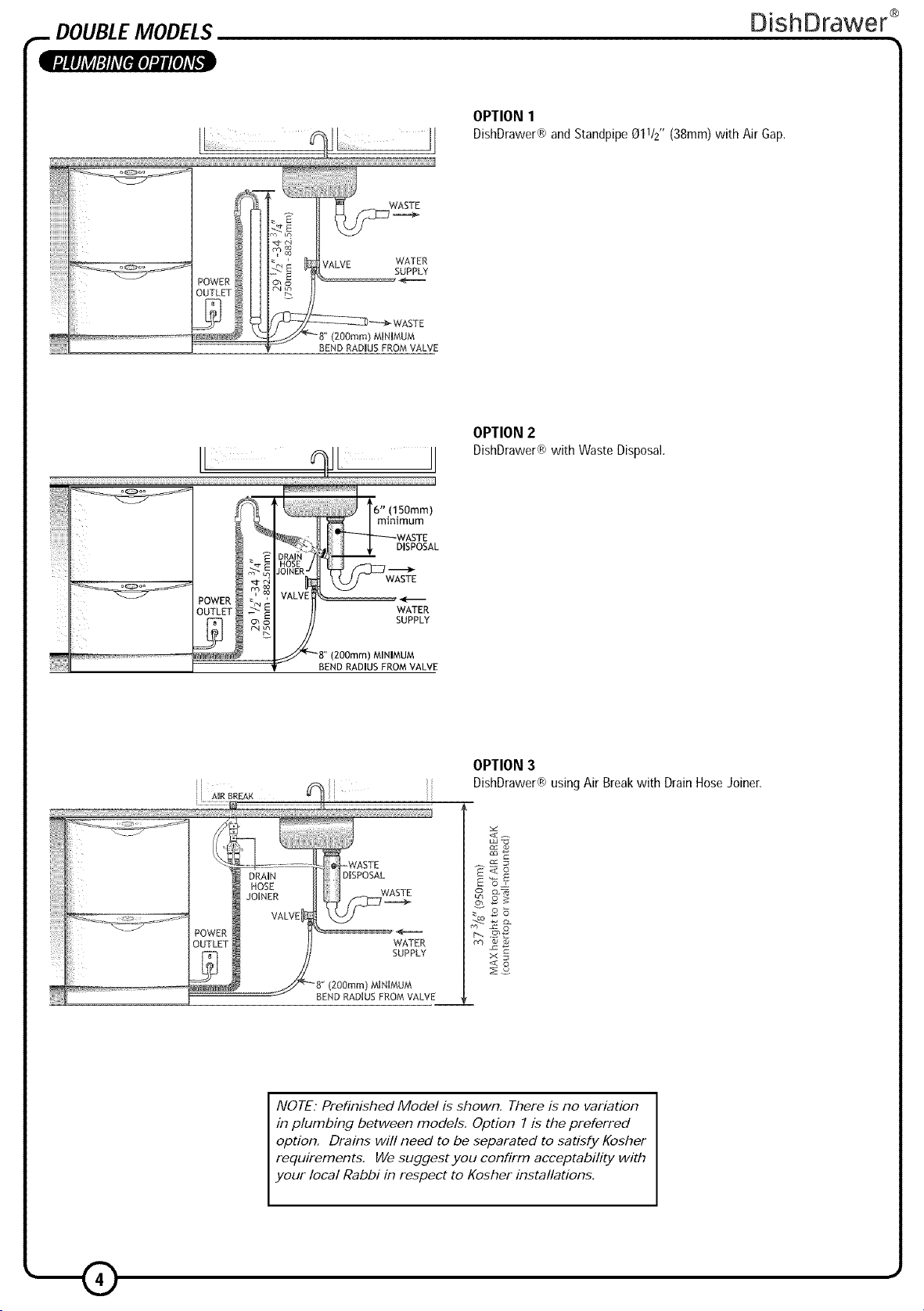
OPTION1
DishDrawer®andStandpipe011/2"(38mm)with AirGap,
VALVE WATER
BEND RADIUS FROM VALVE
SUPPLY
MINIMUM
II qll JI
]
minimum
DISPOSAL
WASTE
WATER
SUPPLY
BEND RADIUS FROM VALVE
MINIMUM
OPTION 2
DishDrawer®with Waste Disposal.
ii _uRBREAK _i ii
OUTLET _ H WATER
NOTE." Prefinished Model is shown, There is no variation
in plumbing between models, Option 1 is the preferred
option, Drains will need to be separated to satisfy Kosher
requirements, We suggest you confirm acceptability with
your local Rabbi in respect to Kosher installations,
OPTION 3
DishDrawer® usingAir Breakwith DrainHose Joiner,
_J _o
x
< o
5J£6££ MOD£ZS
t8 n n!l
WAYER COIIECTIOI
Rcco iicrSc'd IiOl
(l!laxi _ _ 140T160°0},
S pplkd Noseto s(_its/s'(9mm) m _
co npressos ftsg,
WKIER SOFTEIER IIOOELS
RI toyo_ U;;rQi£
for New Re set llll yolff vvatl, r sell Isi._[.
WATER PRESSURE Mxnm /\Aili s m
WaI:_r So I .'Ier Mo:es "145p.s.. ("(I)kFa 14,5 [,,, ("00kFa
OIer I/Io:I;I'> 145 p/>,i, (1000kP_} 4,3 p,;,i, (30kPa)
ORAII COIIECTIOI
/)rialto,:>) oira to'>_i: 01/,_ ' ,i ..... s ' ,i "]6¢ ;[d (/_]s ]6¢ w_sle I )s,
ELECTRICALCOIBIECTIOI
110-120//\C pewc i ll(t, 4.F}Arlp Mir_im_n,
WEIQHT
Ill 93 II (A2kg}P dmiaIed
Enp:y 62 Ib(28kg} Pr ;fisi ;l_:d
.,: (2 m!
_o <,]>I
@ 0
"=_'_ Side View
%
(570_ r_ )
(520_ m)
D a /v{ ' ()per
P elir_is ed _od_l sows
Fela_Btegrae OsOrawer@ epro( ctdept ssp_cifeSwt a_
WI6' (18is} Isteglated Pas(I t ckses ;,
O<pt o pod c exc_ld(sC P,fa r( (s/s6' (30sn)-
pr<l _shed only}, or i18sdle,
LE/QTH OF SERVICES (F[_OMPtOOUC/EXl/ PO/_/
Olas hose 880/10, (2250s m)
Ikt hose-68Vs" ( ;G()mO
Powe sppy ce_: 44' (1125mm)
_>.,_Oll:Sep,/cesappo_na_ly._x pod{ /V%'('89mm losblt;
21%" (£;0 nn from lost; I!P/i' (393mm)los op,
(97mm)
{67mm)
IVIoisIu_e ..... /
ProIecdon I pe
©11//' {38ram} services
hole hnmediaIely
adjacer_I _o c )met,
," car_ be eiIher side
/ ......
OO M? e/q{}tI}
}
/
2 (13ram
mAs'tte
protecIio
t_Voe
....IVlhAmum
Ihick_/ess of
(Z] ZZZZZZZZZZZS
G Yles( I'{Iksindicte no_:i_g
I ) SCIIW loc os,
_f;rto :;l_p I Ig_ 7}
I',,/0[E: AI :ep:: teas r_re/tsaretak)rl
ton t e llosl lac(: el I e a:acelt caDis)ty
I',,_0[E:B_align:IIawe fro_: to ;di_{e :
<aline:y, hei ode:Rio
ce_ia_e :a_b_ ncr_as(/l_n gs'(3rs},
AwARslsQ!
Be s_e th_ edges of tie sei_@ses hob
a_'e smooth e_ co_e_ed. If the services
}_ole is thlr'o_gh a ir_elal ipa_tit olr_the
_ole mist Ir_eI_'otected with the Edge
P_otecto_'/£ovided to II)_'evelr_tdamage to
the/powe_ co_'d o_ Boses.

WASTE
WASYF
51:ND RAVqU f::K(}M VALVE
MINIMUM
OPTION1
S n_:pp @lV2"(38nn)wi Ar()G
OPTION2
Di; Daw;¢ win W_,le Di;pos_.
BEND RAOIUS f RO/v! VALVE
Ii

_ INSTALLATIONINSTRUCTIONS
PLEASE NOTE. Yourmodelof DishDrawer® maydiffer from the modelshown in the installation
diagrams.Installationis similar for all modelsfor either Singleor Doublemodels, Irlom _to[_ cfclr f7
o S_glc _o(_s e@i s 9hlgh _- i_ b_e_Installationdiagramshavebeensimplified to enable
clearerinstruction.FORINTEGRATEDPRODUCTSFOLLOWTHEINTEGRATEDPANELPREPARATION
INSTRUCTIONSPIN 526608, BEFOREMOVINGTHEPRODUCTINTOTHECAVITY.
STEP I: MOVING THEPRODUCTINTOTHECAVITY
MOUNTING TAB OPTIONS
The mounting tabs are in pairs, one on each side of the product, They are
used to secure the product to the cavity sides. Installation requires two
sets of tab pairs be used, DOUBLE MODELS ONLY - _ and _ tab pairs
OR _ and _ tab pairs may be used. All tabs would be optimum.
If the top installation tabs _ are to be used, fit to the chassis by
II
inserting into the top slots as shown. Ensure the tabs are fully
locked in place.
Optional Flexible Extrusion
tl
If the cavity is 24"x 34V2" (610mm x 876mm) flexible extrusions
can be attached along the top and sides of the product, Open the
drawer(s) to expose the chassis trim, Remove extrusion backing
and adhere to the side and top of DishDrawer®. Refer to the
drawing for correct placement.
DishDrawer ®
READTHESEINSTRUCTIONS
COMPLETELYAND CAREFULLY.
_WARNING!
Be careful of
sharp edges,
Important!
DO NOT push
middle of drawer(s).
STEP2: REMOVING THETUB
Be sure that extrusions do not prevent the drawer from closing
completely,
O Check cavity for any obstructions that may interfere with sliding
the product back. DOUBLE MODELS ONLY- loosen the feet first.
II Push product into cavity to suit adjacent cabinetry. Do not push
middle of drawer(s), Be sure inlet, drain hose(s) and power supply
cord are not restricted or damaged by carefully pulling all excess
length through the services hole, while the product is being pushed
back into the cavity,
FOR:;IN(}LE MODELS :h:,ck tha::th:, as:_ el prod c:: s _ot
low_:. [)o _ol_.:,t. gl. o_.:,onyo I r evvBen rovingl ;m
ioll_;cav y,
_po_'tant! (S_N_JLE}aOOELSONLY).
T_e _@_ct may move. }aa_Rchassis _osiitio_ o_'_cavity
SIN_LE/\ODELSOHLY. (_;_::lyo _ h,@aw;rad naklh
elassi posliononl e { wly, b(lore enovingl e
Open the drawer (bottom drawer in DOUBLE MODELS). Release
the tub by depressing the right hand tub clip and pushing it back
13116"(30ram), Repeat on the left hand side.
k
D Lift the tub up off the drawer runners.
Q Slide both runners back into the product,
Placethe tub ontothe floor,
fo MODELS,d_p_{:l _gor tl_ h_ig o e ewiy,
wi ee_ ohe s_@pode_:_-:(/on_c _r,

_ INSTALLATION INSTRUCTIONS
STEP3: ADJUSTING THEFEET (DOUBLE MODELS ONLY)
DishDrawer ®
DOUBLE MODELS ONLY
Adjust the height of the product to suit the cabinetry, by turning the
feet from inside the product using a wrench or M5 socket,
TIP - gently take the load off each foot using the slide and
then turn by hand.
NOTE. For integrated products, the upper panel may be
aligned with the top of the adjacent cabinetry, provided
a minimum 3/76" (Smm)clearance from the counter is
maintained.
Important!
The product must be levelled to within 3/3{' (2.Smm) from front to
back, and side to side.
Important!
The product should NOT support any part of the kitchen cabinetry.
TIP - Place a spirit level on the drawer runners to level the
product.
STEP4: SECURINGTHEPRODUCT
!Ix!:, ....
Ij_ S//H£;LE M'OD£L S O_d£Y
Ceck _ostol_o_ c a:_sss ,til wee nark,_:oral eeav_y,
b,'lor _:(c_ring Ihe p/od_cl,
li_ There are four 5/8" (16mm) round holes, two on the left and two on
the right hand side in the sound insulation. These provide access to
the mounting tabs.
Tosecuretheproductto the cabinetry usea 5/8"(16mm)
Phillipsscrew in eachmountingtab,
Make sure the sound insulation is positioned correctly before
continuing installation.
_]_ DOUBLE MODELS ONLY
Screw the two top tabs to theundersideof bench, Usethe supplied
Phillips5/8" (16mm)screws. Tabscan accommodatea maximumof
3/4"(19mm) verticalgap,

_ INSTALLATIONINSTRUCTIONS
STEP5: ELECTRICALCONNECTION
DishDrawer ®
7
POWER
OUTLET
This view shows the bottom left-hand rear corner with the cover removed
_WARNING!
The product MUST NOT be
plugged in at this stage,
li_Be sure there is a power outlet in reach of the supplied power cord.
If there is not a suitable outlet available then have one installed by a
qualified electrician,
Do not use an extension cord,
li_ Alternatively, the DishDrawer® be connected to a
flexible conduit,
Remove the power supply cord. Remove round knock-out for cable
clamp, Fit suitable cable clamp for the conduit and terminate the
wiring as shown. Terminate the ground wire using the saddle that
was used on the existing earth,
_WARNING!
If permanently connecting be
sure the power is isolated.
permanently
may
/_WARNING!
This must only be done by a certified person.
STEP6: REFITtiNG THETUB
Important!
Before refitting the tub, be sure the hoses are not twisted and the
latches at the rear of each drawer runner are facing forward.
li_To refit the make both of the latches the of each
drawer runner are facing forward, Ensure hoses are hooping
upward, Place the tub on the half open drawer runners and close
the drawer.
i]_ Check the tub clips have reset on both sides of the tub. If not, pull
the tub clips forward until the tub clip button is reset.
tub, sure at rear
Important!
Be sure the tub clips on both sides are reset.

_ INSTALLATIONINSTRUCTIONS
STEP7: CONNECTINGTHEDRAIN HOSE(S)
DRAIN
HOSE
_VENT
WATER
SUPPLY
DishDrawer ®
DishDrawer®with Hose Joiner(see PlumbingOptions).
Remember to slip the wire clip(s) on the drain hose(s) first,
li_ Slip a wire clip over each drain hose, then push the hoses into
the Drain Hose Joiner firmly, 5 clicks, Position the wire clip(s)
between the two positioning ribs on the Drain Hose Joiner.
Attach the Drain Hose Joiner to the waste tee (see Plumbing
Options). Ensure a snug fit. If required a hose clamp may be used.
WASTE
li_ When using the standpipe option (see Plumbing Options), hose(s)
should not extend further than 4314,, (120mm) down the standpipe,
in order to prevent siphoning,
IEI Attach the Drain Hose Support to the cabinetry (with the screw
supplied) to prevent siphoning and to keep the drain hose(s)
from kinking, If required, the Drain Hose(s) may be trimmed to a
suitable length.
STANDPIPE
STEP8: CONNECTINGTHEINLETHOSE
-- WASTE
DISPOSAL
T.--ii_
VALVE WASTE
POWER _ WATER
OUTLET SUPPLY
Important!
Minimum hole size to be connected to the waste tee is 1/2"
(12.7mm).
Be sure the Drain Hose(s) are fully extended to prevent sagging
(see diagram to the left),
The Drain Hose support must be used,
Drain Hosejoiner must not support weight of hoses. Keep
excess length of Drain Hose on the DishDrawer® side of the
Drain Hose support ortrim to suit,
_WARNING!
DO NOT plug the product in
at this stage,
_]J Connect the Inlet Hose to the water supply. Be sure the sealing
washer is in place, The hose coupling must be tightened a further
half turn after seal contact,
TIP - Turn the water valve ON to check for any leaks,
Alternatively flexible stainless steel hose can be plumbed directly to
the inlet valve using a 3/8" brass adaptor (p/n 526161) available from
the nearest Fisher & Paykel Authorized Service Agent,
Important!
DO NOT cut the inlet hose.
MINIMUM
BEND RADIUSFROMVALVE
NOTI _ _2HGL E M J/7/?S DO NOT 1IA Ill A TOE KICK TO
IH.%:72_LL_ t/_OC L? 70 7Y/?/VAL CHICK I%:Z
? E ?

_ INSTALLATIONINSTRUCTIONS
STEP9: MEASURING THETOEKICK(DOUBLEMODELS ONLY)
DishDrawer ®
!_1 Partially the bottom drawer, Turn Prefinished Toe Kick
open
upside down and hold vertically against the bottom edge of the
Tub side (not the drawer front),
Mark the position of the bottom edge of the Tub side on the Toe Kick,
Choose the nearest groove to the pencil mark which will result
in the shortest Toe Kick.
STEP10: TRIMMING THETOEKICK(DOUBLE MODELS ONLY)
Important!
Before cutting ensure the Toe Kick is positioned on a wooden
chopping board to avoid damage to surrounding area.
I_On the chosen groove cut down the vertical ribs at the centre and
the ends using a knife, Cut along full length with a knife, Turn Toe
Kick over, bend and then cut from front, Sand or scrape bottom edge
to remove rough patches,
_WARNING!
Remove all sharp edges
l_To avoid a cutting hazard remove a//sharp edges after trimming,
!
I_ Remove Toe Kick tabs by snapping them off.

_ INSTALLATIONINSTRUCTIONS
STEP11:FITTINGTHETOEKICKTOTHEPRODUCT(DOUBLEMODELS ONLIt)
Toekick
mountingrails
_"_1 Partly open bottom drawer. Position Toe Kick behind door and slide
onto the mounting rails on the underside of tub,
DishDrawer ®
!
\
|
STEP 12: FINAL CHECKLIST(DOUBLE AND SI#JGLE MODF//,,%)
_ _1111
O Be sure product is level, securely fastened to the cabinetry and TROUBLESHOOTING
opens and closes freely, The BishBrawer® must be free to close
with no resistance from the cabinetry. 0 Excessive water remaining above the filter plate, after the
O Be sure the inlet hose to valve connection is tightened a further half .. '
turn after seal contact, connec[ion.
O Be sure any knock-outs or plugs in drain connection have been 0 No water supply; check water is connected, ON and there is
drilled out and drain connection has been made, the specified water pressure.
O Turn ON the power and water supply. The DishDrawer® should O DishDrawer® does not light up when the tub is opened;
beep and light up, be sure power is connected and is switched ON,
.... rinse cycle check for kinked drain hoses or blocked waste
_ Close bottom drawer, check if flush with adjacent cabinetry,
If required open drawer and adjust,
Note. Clearance between Toe Kick and floor must be
15/32"(12mm) minimum,
When Toe Kick is in position, open bottom drawer and gently fasten
the Toe Kick screws, on each side.
Important!
DO NOT over tighten screws.
Overtightening will damage the plastic mounting detail.
O OaP:enl_l:d drh:ckr l_ean dr; h:rCk op_rrat;: n ?afcT__ fPrreOegrt:mo_a_nt,rol O Water around water supply and drainage connections - _
P Y ( ) P ' check connections, existing plumbing and hoses for leaks,
0 On the Wash Program Control Panel select Rinse and close the .
drawer(s), Start the program by pressing the Start!Pause button. , _ ., ,
O After the Rinse program has finished, be sure the machine has run
and drained correctly, O If unable to resolve, contact your Customer Care Centre,
O Check water supply and drainage connection for leakage.
0 Repeat for each Drawer, _
0 If a fault occurs consult the Fault Code Section of the
user buloe,
STEP 13: CUSTOMERCARE
If you have any questions concerning the installation of this DishDrawer®,
please contact your Fisher & Paykel Authorized Service Agent,
FORTHE UNITED STATES OF AMERICA (USA) & CANADA
Fisher& PaykelAppliances
5900Skylab Road
HuntingtonBeach
CA92647
PHONE TOLL FREE 1888 9 FNP USA
18889 367 872
www usa HsherpaykeL corn
 Loading...