

Page 1

DOUBLE DISHDRAWER™ DISHWASHER
DD60DA & DD60DC
models
INSTALLATION GUIDE
NZ AU GB IE SG
591151D 05.19
Page 2

Page 3
1 SAFETY AND WARNINGS
! !
WARNING!
WARNING!
Electrical shock hazard
Before installing the dishwasher,
remove the house fuse or open
the circuit breaker.
This appliance must be earthed.
In the event of a malfunction
or breakdown, earthing will
reduce the risk of electric shock
by providing a path of least
resistance for electric current. This
appliance is equipped with a cord
having an equipment-earthing
conductor and an earthing plug.
The plug must be plugged into an
appropriate outlet that is installed
and earthed in accordance with
all local codes and ordinances.
Electrical shock hazard
WARNING- Improper connection
of the equipment-earthing
conductor can result in a risk
of electric shock. Check with a
qualified electrician or service
representative if you are in doubt
as to whether the appliance is
properly earthed.
Do not modify the power supply
plug provided with the appliance
- if it will not fit the outlet, have
a proper outlet installed by a
qualified electrician. Do not use
an extension cord, adapter plug or
multiple outlet box.
Failure to follow this advice may
Failure to follow this advice may
result in electrical shock or death.
result in electrical shock or death.
!
WARNING!
Cut Hazard
Take care - panel edges are sharp.
Failure to use caution could result
in injury or cuts.
IMPORTANT!
SAVE THESE INSTRUCTIONS
The models shown in this installation guide may not be available in all markets and are subject to change at any time. For current details about model and specification availability in your country,
please go to our website www.fisherpaykel.com or contact your local Fisher & Paykel dealer.
1
Page 4

1 SAFETY AND WARNINGS
IMPORTANT SAFETY INSTRUCTIONS
O
Installation of this dishwasher requires
basic mechanical and electrical skills.
O
Be sure to leave these Instructions with
the Customer.
O
Installation must comply with your local
building and electricity regulations.
O
At the completion of the dishwasher
installation, the Installer must perform
the Final Checklist.
O
Remove all packaging materials
supplied with the dishwasher.
O
This dishwasher is manufactured for
indoor use only.
O
Ensure all water connections are
turned OFF. It is the responsibility of
the plumber and electrician to ensure
that each installation complies with all
Codes and Regulations.
O
The dishwasher MUST be installed
to allow for future removal from the
enclosure if service is required.
O
The switched power outlet must be
outside the dishwasher cavity, so that it
is accessible after installation.
O
Care should be taken when the
appliance is installed or removed to
reduce the likelihood of damage to the
power supply cord and hoses.
IMPORTANT SAFETY INSTRUCTIONS
O
If the dishwasher is to be relocated
from one installation to another
it must be kept upright to avoid
damage from water spillage.
O
Make sure only new hoses are used
for connection (supplied with the
dishwasher). Old hoses should not be
reused.
O
Failure to install the dishwasher
correctly could invalidate any
warranty or liability claims.
O
If the product is installed in a motor
vehicle, boat or similar mobile facility,
you must bring the vehicle, boat or
mobile facility containing the product
to the service shop at your expense
or pay the service technician’s travel
to the location of the product.
2
Page 5
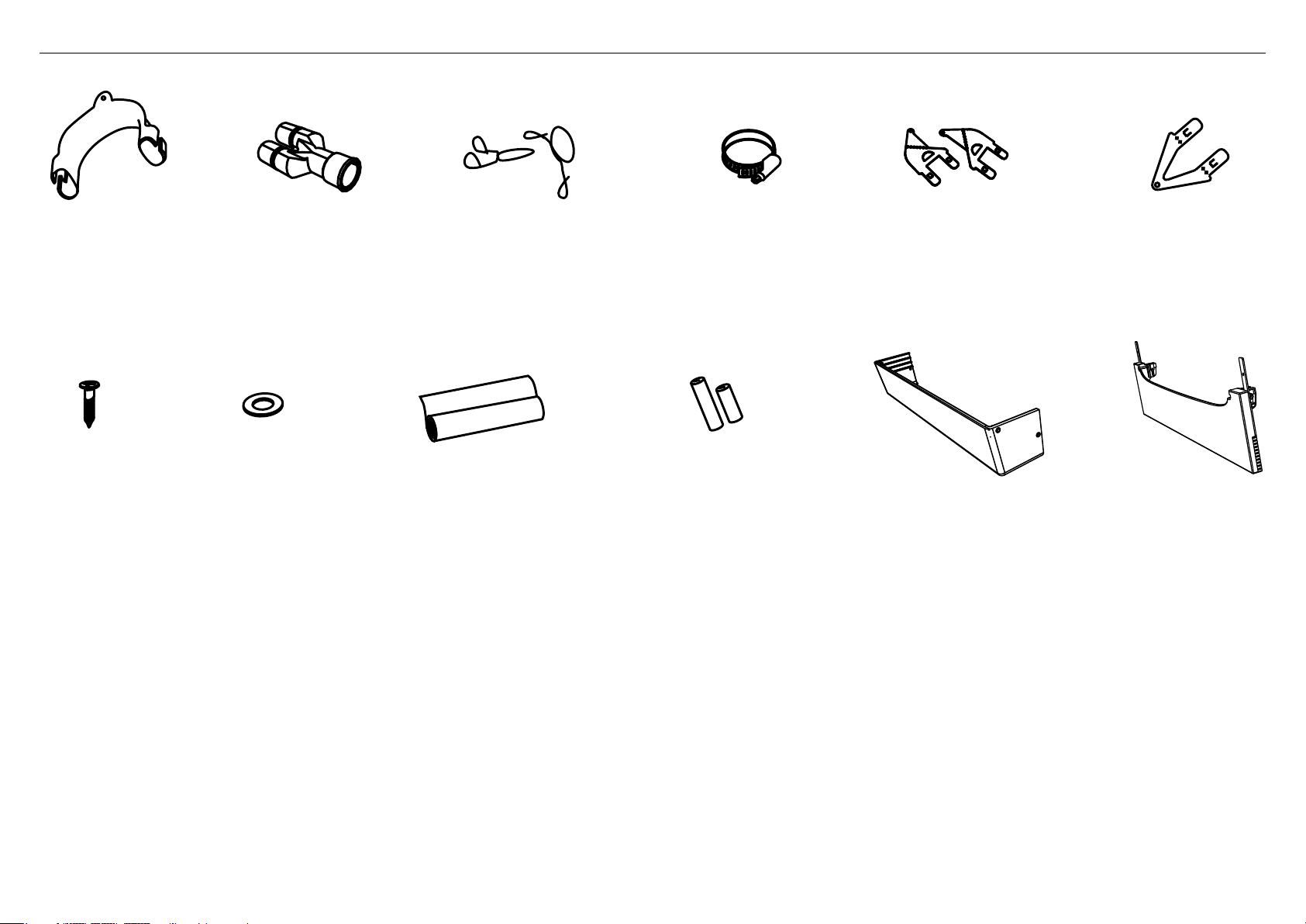
2 PARTS SUPPLIED
Drain hose
support (1)
Phillips
16 mm
screws (9)
If the Drain hoses supplied are not long enough to reach your services, you must use a Drain Hose Extension Kit P/N 525798 which will extend the drain hoses by 3.6 m.
The kit is available from the nearest Fisher & Paykel Authorised Service Centre or our local website listed at the end of this document.
Rubber washer
for inlet hose (1)
(comes already
fitted)
Drain hose
joiner (1)
Moisture protection
tape (1)
(to prevent moisture
damage to cabinetry)
Wire clip (2)
(for securing
Drain hose joiner)
Clamp (1)
(for securing
Drain hose joiner)
Hexagonal
socket for feet
adjustment (2)
(long & short)
Side mounting
bracket kit
(A and B) (2)
OPTIONAL
DD60DA models only
Prefinished toekick (1)
and securing pins (4)
Top
mounting
brackets (2)
OPTIONAL
DD60DC models only
Prefinished toekick (1)
Dishdrawer™ installation overview
This video provides an overview of what is needed to install a DishDrawer™. It is intended as an overview only of the installation process and is not intended to be
used as a guide on how to install a DishDrawer™ yourself. https://vimeo.com/325297597
3
Page 6
N
F
C
L
M
A
G
B
E
D
O
I
H
J
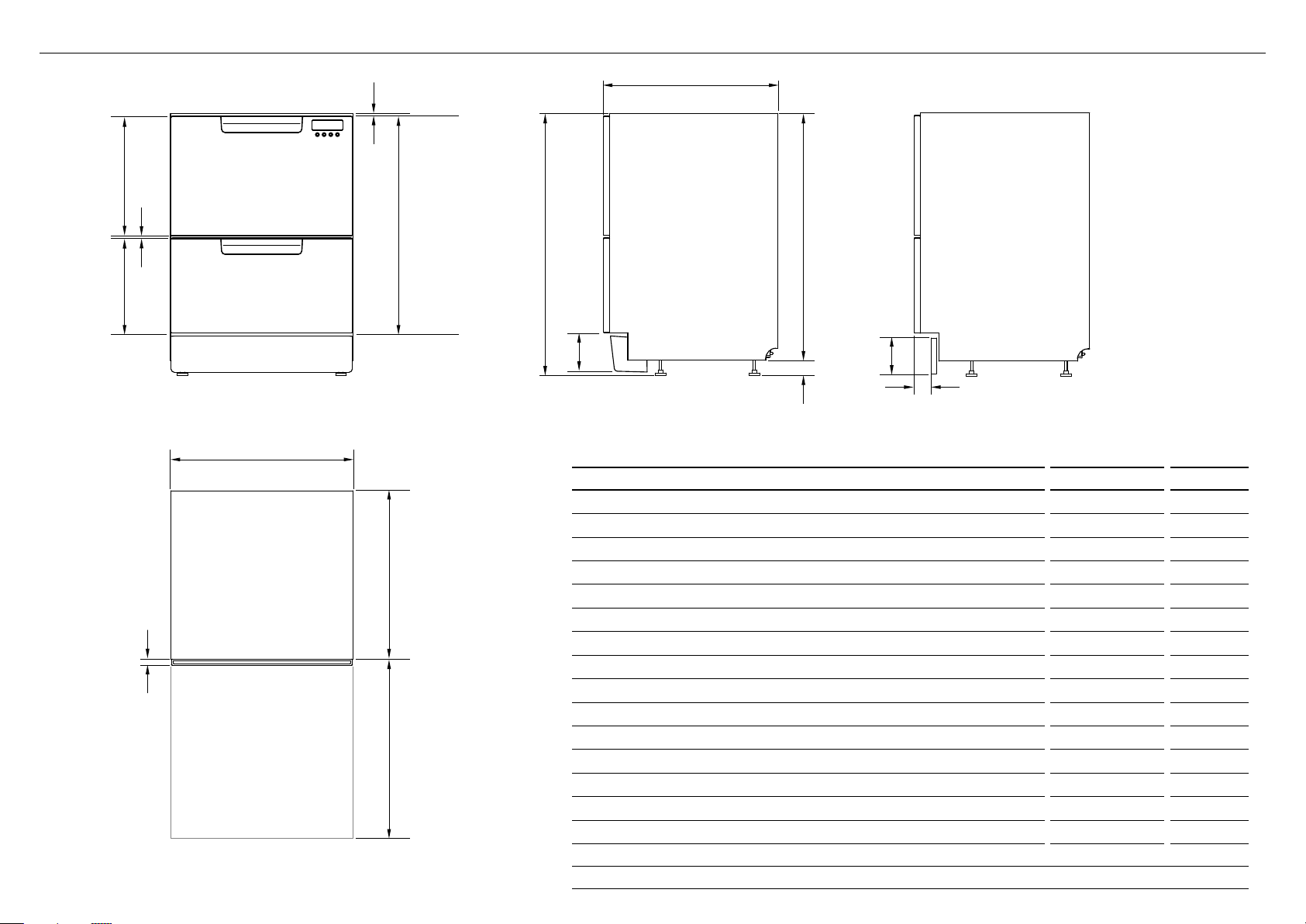
3 PRODUCT DIMENSIONS
DD60DC MODELSDD60DA MODELS
K
FRONT
PLAN
4
L
PROFILE PROFILE
PRODUCT DIMENSIONS MM MM
Overall height of product
A
Overall width of product 599 599
B
Overall depth of product 573 573
C
Depth of chassis (to back of front drawer panel) 553 553
D
Depth of drawer front panel 20 20
E
Height of chassis
F
Height of drawer front panels 712 712
G
Height of upper drawer front panel 393 393
H
Height of lower drawer front panel 312 312
I
Height from top of drawer front panel to top of chassis 8 8
J
Ventilation gap between drawer front panels 7 7
K
Height of toekick (customisable) 70-120 72-127
L
Depth from front of drawer panel to front of toekick (adjustable)
M
Height of levelling feet (adjustable) 9-69
N
Maximum extension of drawer 547 547
O
1
includes 2mm high bracket slots2 depending on adjustment of levelling feet
3
adjustable to match toekick recess on adjoining cabinetry
1
1
DD60DA DD60DC
820-8802820-880
811 811
3
NA 38-54
2
9-69
2
2
Page 7
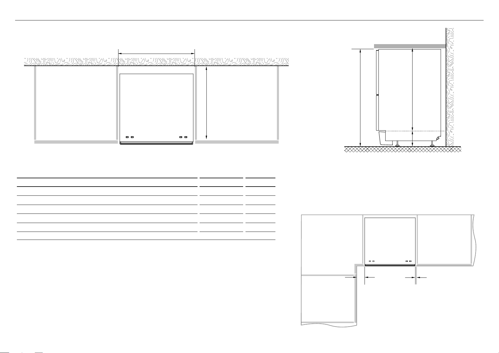
4 CABINETRY DIMENSIONS
R
Q
P
S
T
Bracket slots
PLAN
DD60DA DD60DC
CABINETRY DIMENSIONS MM MM
Inside height of cavity* min. 820 min. 820
P
Inside width of cavity 600 600
Q
Inside depth of cavity min. 560 min. 560
R
Recommended height of adjacent cabinet space 720 720
S
Height of toekick space* 100-160 100-160
T
* depending on adjustment of levelling feet
PROFILE
Minimum clearances from adjacent cabinetry
min. 13 mm
clearance
from a corner
cupboard
min. 2 mm
clearance
to adjacent
cupboard door
5
Page 8
COUNTERTOP
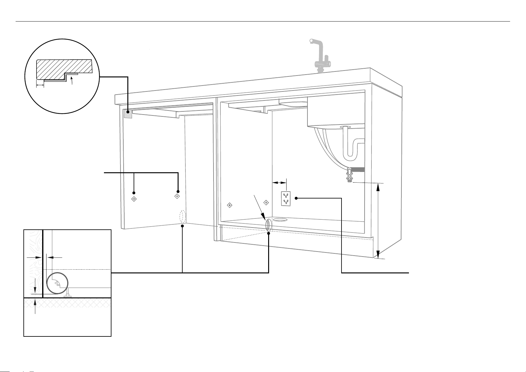
5 CAVITY PREPARATION
10 mm
Moisture
protection tape
must be applied
These marks indicate formed
bracket screw locations, if
securing by drawer removal.
If there is no side partition, you
can construct timber bracing
as something to secure into.
WARNING!
Incorrect placement of the hole
will result in damage to hoses.
Max 5mm
Max distance
between hole edge
and rear inner face
max. 450mm
Ø 57mm
Service Holes
Can be located either side of dishwasher, close to the rear face and
the floor, as illustrated, for access to the water supply and drain.
min. 200mm
Water Connection
Recommended COLD
(Maximum 60°C).
3/4“ BSP (GB20) to
suit flat washer.
Water Pressure
Water softener models
Max. 1 MPa (145 psi)
Min. 0.1 MPa (14.5 psi)
Models without water softener
Max. 1 MPa (145 psi)
Min. 0.03 MPa (4.3 psi)
Kosher requirements
Drains will need to be
separated to satisfy kosher
requirements. We suggest
you confirm acceptability with
your local rabbi in respect to
kosherinstallations.
IMPORTANT!
The power outlet must be
located in a cabinet adjacent
to the dishwasher cavity.
220-240 VAC min. 9.5 A
Max 10mm
Max distance between
hole edge and floor
6
O
If the hole is through wood, make sure its edges are smooth
androunded.
O
If the hole is through metal, ensure you fit the supplied Edge
Protector to prevent damage to the power cord.
Page 9
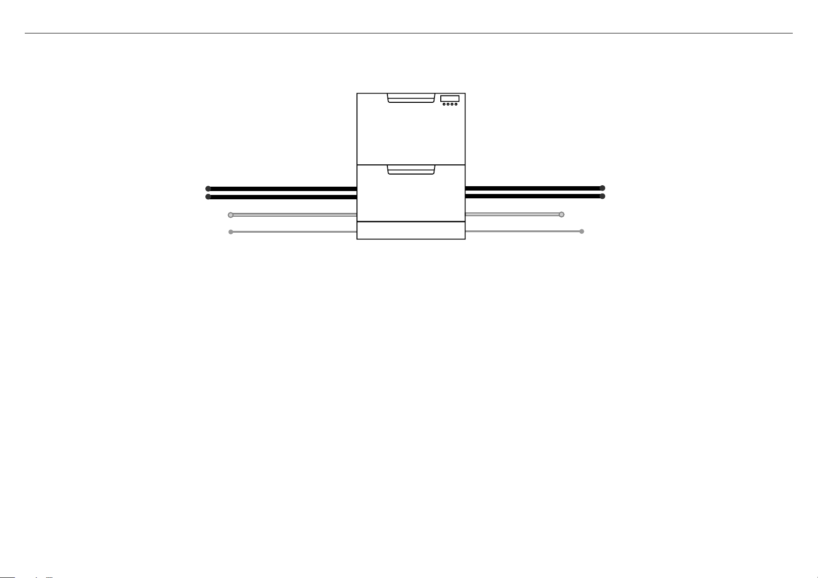
6 MAXIMUM DISTANCE OF HOSES & CORD FROM CHASSIS EDGE
LEFT HAND SIDE
Drain hoses - 2000 mm Drain hoses - 1800 mm
Inlet hose - 1650 mm Inlet hose - 1250 mm
Power cord (excl.plug) - 1650 mm Power cord (excl.plug) - 1650 mm
RIGHT HAND SIDE
7
Page 10
NOW CHOOSE WHICH INSTALLATION METHOD (A) OR (B)
IS MORE SUITABLE FOR YOUR CABINETRY...
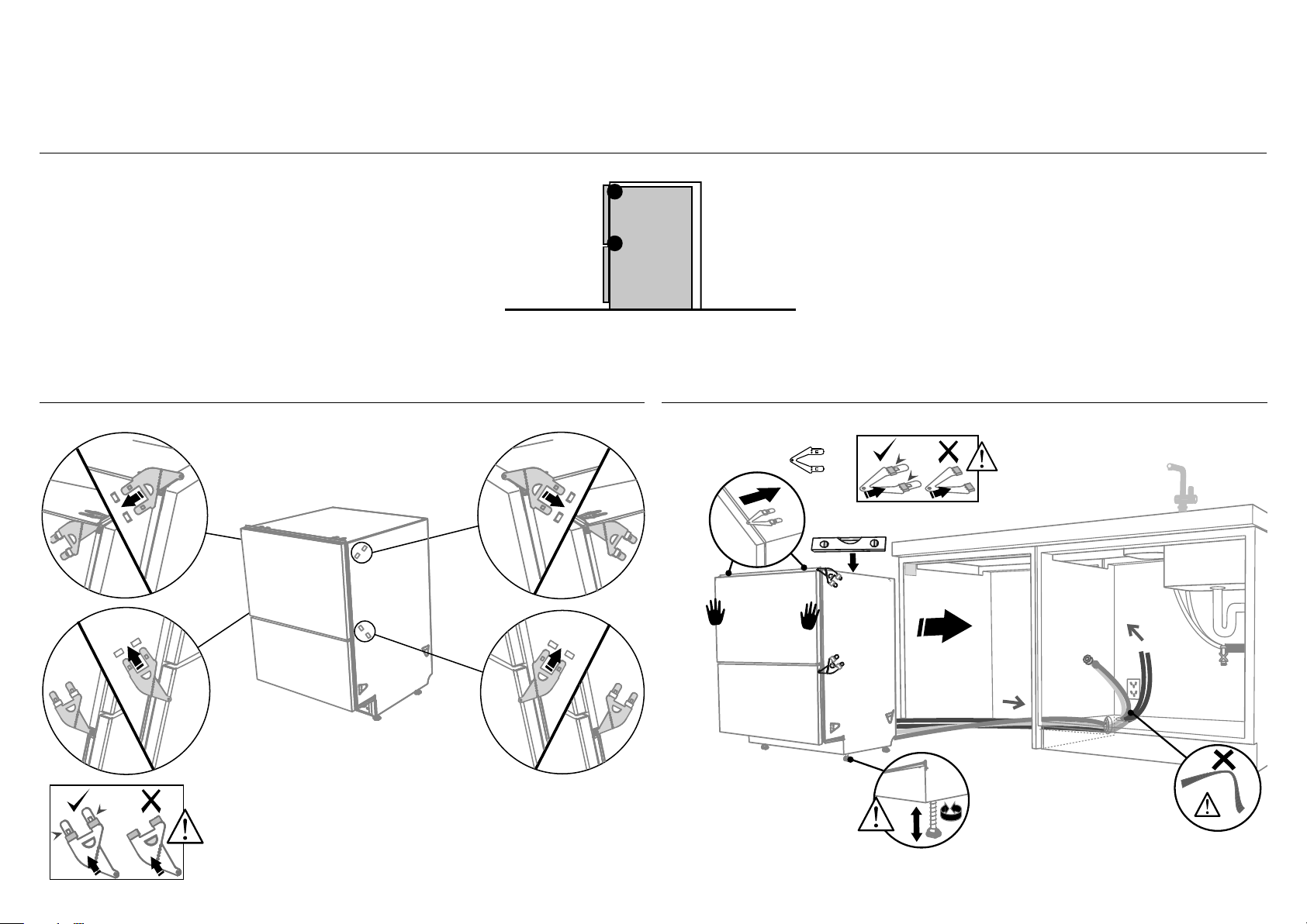
7 RECOMMENDED METHOD (A) - SECURE WITHOUT DRAWER REMOVAL (FRAMELESS CABINETRY ONLY)
8-A ATTACH SIDE MOUNTING BRACKETS 9-A PULL THROUGH HOSES & PUSH INTO THE CAVITY
Clip all four side mounting brackets
into their slots using a flat-bladed
screwdriver. Ensure they’re securely
fitted before sliding product into cavity.
AB
optionally attach the
two top mounting brackets
(x2)
Initially level the product
When fitting brackets, ensure
the ends are not pushed
down into the chassis.
B
A
A
B
A
The mounting slots are in pairs, one on
each side diagonally across the product.
A bracket must match A slot and B
bracket must match B slot.
When fitting brackets, ensure the ends
are not pushed down into the chassis.
B
You can raise or lower the
product by twisting the feet.
Then take care when pushing
the product into the cavity
that you do not bend the feet.
As you push product
in, pull through hoses
and cord, ensuring
they don’t get kinked
or twisted.
8
Page 11
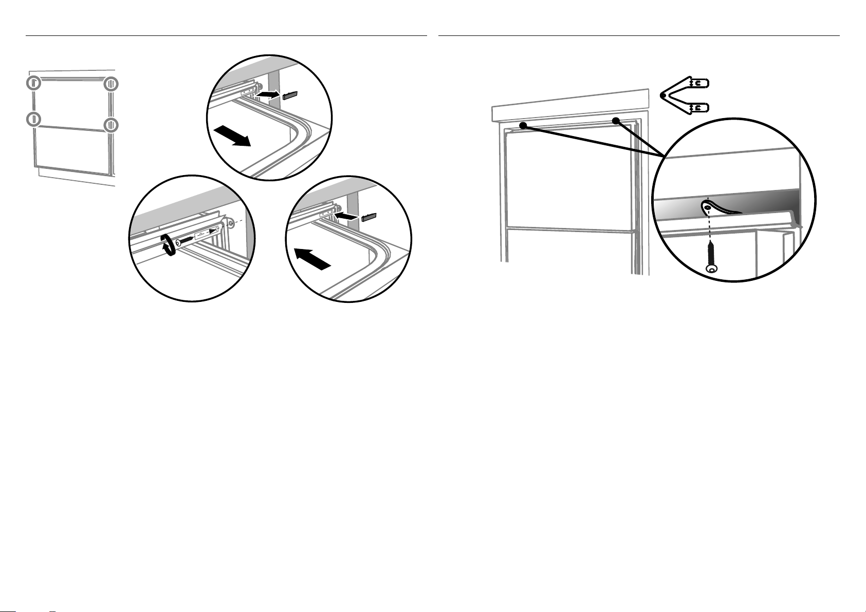
!0-A SECURE TO THE CABINETRY ON THE SIDES
!1-A OPTIONALLY SECURE TO THE CABINETRY ABOVE
Using a small Philips
screwdriver, screw
through the trim
moulding, securing the
side mounting bracket
to the cabinetry.
Do not damage the
rubber trimseal.
Open the drawer
halfway. Using
a flat bladed
screwdriver, prise
the grey rubber
plug out of the
trim moulding.
2
Repeat for all
four brackets.
1
Replace the grey
rubber plug back into
the trim moulding
and ensure the trim
seal is facing forward.
The top mounting
brackets will only
(x2)
bend upwards a
maximum of 10 mm.
3
!2-A AFTER SECURING, DEPENDING ON YOUR MODEL - REFER TO RELEVANT ‘FIT THE SUPPLIED TOEKICK PANEL’ STEP
9
Page 12

7 ALTERNATIVE METHOD (B) - SECURE BY DRAWER REMOVAL
8-B PULL THROUGH HOSES & PUSH INTO THE CAVITY 9-B REMOVE THE LOWER DRAWER
optionally attach the
two top mounting
brackets
(x2)
Initially level the product
You can raise or lower
the product by twisting
the feet. Then take
care when pushing the
product into the cavity
that you do not bend
the feet.
10
When fitting brackets,
ensure the ends are
not pushed down into
the chassis.
As you push product
in, pull through hoses
and cord, ensuring
they don’t get kinked
or twisted.
1
2
100 mm
Press the release tabs
in on either side and
push back to release
drawer from runners.
Lift drawer off runners.
To prevent kinked hoses
Either sit the drawer down on the left hand
side (recommended) or rotate the drawer
clockwise, resting it on its side after removal.
3
4
Push drawer
runners back in
Sit the drawer down
on either side.
3
4
Push drawer
Rotate the drawer
clockwise (max. 90
and rest on side.
o
)
runners back in
on either side.
Page 13

!0-B SECURE TO THE CABINETRY ON THE SIDES !1-B OPTIONALLY SECURE TO THE CABINETRY ABOVE
For further adjustment,
using the most appropriate
length Hexagonal socket
supplied, fully extend
levelling feet up to
required distance by hand.
Secure using two pairs
of formed brackets.
Repeat on the other
side of the chassis.
(x2)
The top mounting
brackets will only
bend upwards a
maximum of 10 mm.
x4
Before refitting the
drawer, ensure the hoses
are not twisted and the
latches at the rear of
each drawer runner are
facing forward.
Hexagonal
socket
2
Ensure product is level and
aligning with cabinetry.
1
!2-B REFIT THE DRAWER ONTO THE RUNNERS
Lift or rotate anti-clockwise the
drawer back onto the drawer runners
on either side.
3
Release tab
4
100 mm
Pull the release tabs forward on both
sides 100 mm. Ensure the tabs are fully
pulled forward and click into place.
!3-B AFTER SECURING, DEPENDING ON YOUR MODEL - REFER TO RELEVANT ‘FIT THE SUPPLIED TOEKICK PANEL’ STEP
11
Page 14

!4 FIT THE SUPPLIED TOEKICK PANEL - DD60DA MODELS ONLY
HEIGHT OF
TOEKICK
min.12 mm
clearance
115 mm
Measure how high the toekick should
be based on min. 12 mm clearance to
floor and the table below.
HEIGHT FROM FLOOR TO
BOTTOM OF DOOR (MM)
100-114 3
115-129 2
130-144 1
145-160 0
min.2 mm
clearance
1
On a board, lay the toekick on its
Cutoff Sections
NUMBER OF CUTOFF SECTIONS
TO REMOVE FROM PANEL
side and carefully score/cut down the
corner to where the cutoff will be.
There are 3 preset height positions.
Carefully bend and snap off the side.
Repeat in the opposite corner.
19
2
19
Once the sides are removed, score/cut all the
way down the middle of the toekick.
Carefully bend and snap off.
4
3
Use a file to smooth the top edges.
5
6
7
8
Using a hammer and screwdriver,
punch out the two mounting hole
locations as shown.
Repeat on the opposite side.
5
Mount the toekick into position over the
cowling. Ensure the holes in the toekick
match up with the mounting hole positions
on the cowling. Push the two pins in to
secure. Repeat on the opposite side.
if after fitting, the drawer touches the floor with a full load, you need to remove more of the toekick panel:
A Remove the lower drawer (see ALTERNATIVE METHOD (B) - SECURE BY DRAWER REMOVAL - STEP 8 B: REMOVE THE LOWER DRAWER)
B Remove the pins - use a pair of needle nose pliers to press the pin legs together and push back through the hole
C Remove the panel, and cut off another section of the kick strip following steps 2-8 above.
D Replace the drawer (see ALTERNATIVE METHOD (B) - SECURE BY DRAWER REMOVAL - STEP 11 B REFIT THE DRAWER ONTO THE RUNNERS)
E Continue from step 7 above.
12
Page 15

!4 FIT THE SUPPLIED TOEKICK PANEL - DD60DC MODELS ONLY
Where the toekick
meets the bottom
of the tub is the
cut-off point
1
2
Mark this point on the
toekick with a pencil
3
Lay the toekick face down on
a chopping board or similiar
4
19
Score along the marked
cutoff line with a knife
5
19
Turn the toekick over and
score along the same line
6
Gently snap off the excess
7
Smooth the edges with a file.
Be careful of sharp edges.
8
Snap off the two end tabs
Mounting rail
9
Slide the toekick onto
the mounting rails
either side and screw
the toekick onto the
bottom of tub on
either side.
IMPORTANT!
Do not overtighten screw.
13
Page 16

!5 THERE ARE TWO DIFFERENT PLUMBING AND DRAINAGE OPTIONS. CHOOSE WHICH IS MORE SUITABLE.
Dishwasher and Ø 38 mm Standpipe
Screw Drain hose
support to back wall
at correct height.
If space is limited
for fixing, push
hose through drain
hose support
to required height.
DRAINAGE OPTION 1
max.
2
120mm
1
750-883 mm
38mm
step 16
Dishwasher using drain hose joiner onto sink trap/waste tee
DRAINAGE OPTION 2
Screw Drain hose
support to back wall
at correct height.
If space is limited
for fixing, push
hose through drain
hose support
to required height.
2
750-883 mm
1
step 16
Supplied drain
hose joiner to suit
19 mm waste tee
3
14
min. 500 mm
min. radius
200 mm
IMPORTANT!
Ensure that drain hose is installed as close to the underside of the
benchtop as possible. This will ensure no waste re-enters the drain hose
in the event of poor flow or a blockage in the plumbing.
Ensure the drain hose does not extend into water retained in the trap; an
airgap is required to prevent waste water from siphoning back into the tub.
IMPORTANT!
Ensure that drain connection complys with local plumbing regulations.
750 - 883 mm
min. radius
200 mm
Ensure drain hose is routed
straight to the joiner so
that waste water does not
accumulate in the hose.
Remove excess drain hose
material if necessary.
Do not shorten the inlet hose.
min. 500 mm
750 - 883 mm
Page 17

!6 CONNECT INLET HOSE TO COLD WATER !7 PLUG PRODUCT IN
min.
10mm
3/4” BSP connector
180
o
No leaks!
Ensure the supplied
rubber washer is fitted
inside the coupling.
1
Tighten coupling with spanner.
2
!8 TROUBLESHOOTING
O
Excessive water remaining above the filter plate, after the rinse cycle. (This is displayed as an A3 fault)
Check for a kinked drain hose, blocked waste connection, highloop not properly installed, drain hose not routed correctly or spray arms not in place.
O
No water supply. (This is displayed as an A1 fault)
Check water is connected and turned on.
O
The dishwasher is beeping continuously
There is a fault. See section ‘If there is a fault’ in the User guide for further information and instructions.
O
No program indicator lights up when the drawer is opened
Ensure power is connected and is switched on. If it is and still no indicator ligths up, see the ‘Preference options’ section of the ‘Quick start guide’. An option called ‘Open drawer auto power-on’
may need to be turned on.
O
Water around water supply and drainage connections
Check connections, existing plumbing and hoses for leaks. Check rubber washer and hose clamp are correctly fitted.
O
If product is tipping
Ensure the product is secured to the cabinetry.
O
If front panels are misaligned
Check and relevel product. Unscrew the product from the cabinetry. Adjust the feet to level the product, then re-secure to the cabinetry. Check the cabinetry is square.
O
Drawer doesn’t close properly
Ensure nothing is obstructing the drawer from closing properly eg hoses or drawer latches.
O
If a problem occurs, consult the ‘Troubleshooting’ section of the User guide.
O
If after checking these points you still need assistance, please refer to the Service & Warranty book for warranty details and your nearest Authorised Service Centre, or contact us through our
website, listed below.
15
Page 18

TO BE COMPLETED BY THE INSTALLER
!9 FINAL CHECKLIST
Check all parts are installed.
Ensure that all panels and parts thereof are secure and final electrical tests have
been conducted in accordance with local electrical regulations.
Ensure product is level, securely fastened to the cabinetry and opens and closes
freely. The drawers must be free to fully close with no resistance from the cabinetry.
Ensure inlet hose to water supply has supplied rubber washer fitted, and that it’s
tightened a further half turn after seal contact.
Ensure any knockouts or plugs in drain connection have been drilled out and drain
connection has been made.
The drain hose joiner must not support the weight of excess hose material.
Keepdrain hose as fully extended as possible to prevent sagging. Any excess
length of drain hose should be kept on the dishwasher side of the highloop.
If connecting the drain hose to the sink trap, ensure the Highloop is a minimum
150mm higher than the drain hose joiner.
Ensure any packaging or tape securing the racks or spray arms is removed from
the drawers.
Water softener models only: adjust the water softener setting from the default
setting to suit the water hardness of the area.
See the Quick start guide and section ‘Water softener’ in the User guide.
Turn on the power and water supplies, then open the drawers. You should hear a
beep and see a program indicator light up on the control panel.
Check the spray arms are in place, mounted correctly and free to rotate, by
physically rotating by hand.
Spray arm
Add three cups of water into the drawer. Press
until the indicator of the ‘Rinse’
program lights up. Close the drawer and press to start the program.
Repeat for the other drawer.
After the Rinse program has finished, ensure the dishwasher has run and
drainedcorrectly.
Check the water supply has correctly shut off and drainage connection for leakage.
Complete and keep for safe reference:
Model
Serial No.
Purchase Date
Purchaser
Dealer Address
Installer’s Name
Installer’s Signature
Installation Company
Installation Date
16
FISHERPAYKEL.COM
Copyright © Fisher & Paykel Appliances 2019. All rights reserved.
The product specifications in this booklet apply to the specific products
and models described at the date of issue. Under our policy of continuous
product improvement, these specifications may change at any time. You
should therefore check with your Dealer to ensure this booklet correctly
describes the product currently available.
Page 19

17
Page 20

SINGLE DISHDRAWER™ DISHWASHER
DD60SA & DD60SC
models
INSTALLATION GUIDE
NZ AU GB IE SG
591151D 05.19
Page 21

Page 22

1 SAFETY AND WARNINGS
! !
WARNING!
WARNING!
Electrical shock hazard
Before installing the dishwasher,
remove the house fuse or open
the circuit breaker.
This appliance must be earthed.
In the event of a malfunction
or breakdown, earthing will
reduce the risk of electric shock
by providing a path of least
resistance for electric current.
This appliance is equipped with
a cord having an equipmentearthing conductor and an
earthing plug. The plug must be
plugged into an appropriate outlet
that is installed and earthed in
accordance with all local codes
Electrical shock hazard
WARNING- Improper connection
of the equipment-earthing
conductor can result in a risk
of electric shock. Check with a
qualified electrician or service
representative if you are in doubt
as to whether the appliance is
properly earthed.
Do not modify the power supply
plug provided with the appliance
- if it will not fit the outlet, have
a proper outlet installed by a
qualified electrician. Do not use
an extension cord, adapter plug or
multiple outlet box.
Failure to follow this advice may
and ordinances. Failure to follow
result in electrical shock or death.
this advice may result in electrical
!
shock or death.
WARNING!
Cut Hazard
Take care - panel edges are sharp.
Failure to use caution could result
in injury or cuts.
IMPORTANT!
SAVE THESE INSTRUCTIONS
The models shown in this installation guide may not be available in all markets and are subject to change at any time. For current details about model and specification availability in your country, please go to
our website www.fisherpaykel.com or contact your local Fisher & Paykel dealer.
1
Page 23

1 SAFETY AND WARNINGS
IMPORTANT SAFETY INSTRUCTIONS
O
Installation of this dishwasher requires
basic mechanical and electrical skills.
O
Be sure to leave these Instructions with
the Customer.
O
Installation must comply with your local
building and electricity regulations.
O
At the completion of the dishwasher
installation, the Installer must perform
the Final Checklist.
O
Remove all packaging materials
supplied with the dishwasher.
O
This dishwasher is manufactured for
indoor use only.
O
Ensure all water connections are
turned OFF. It is the responsibility of
the plumber and electrician to ensure
that each installation complies with all
Codes and Regulations.
O
The dishwasher MUST be installed
to allow for future removal from the
enclosure if service is required.
O
The switched power outlet must be
outside the dishwasher cavity, so that
it is accessible after installation.
O
Care should be taken when the
appliance is installed or removed
to reduce the likelihood of damage
to the power supply cord and hoses.
IMPORTANT SAFETY INSTRUCTIONS
O
If the dishwasher is to be relocated
from one installation to another
it must be kept upright to avoid
damage from water spillage.
O
Make sure only new hoses are used
for connection (supplied with the
dishwasher). Old hoses should not
be reused.
O
Failure to install the dishwasher
correctly could invalidate any
warranty or liability claims.
O
If the product is installed in a motor
vehicle, boat or similar mobile facility,
you must bring the vehicle, boat or
mobile facility containing the product
to the service shop at your expense
or pay the service technician’s travel
to the location of the product.
2
Page 24

2 PARTS SUPPLIED
Drain hose
support (1)
Phillips
16 mm
screws (7)
If the Drain hoses supplied are not long enough to reach your services, you must use a Drain Hose Extension Kit P/N 525798 which will extend the drain hoses by 3.6 m.
The kit is available from the nearest Fisher & Paykel Authorised Service Centre or our local website listed at the end of this document.
38 mm
bottom fixing
screws & metal
washers (2)
Drain hose
joiner (1)
Rubber washer
for inlet hose (1)
(comes already
fitted)
Wire clip (1)
(for securing
Drain hose joiner)
Moisture protection
tape (1)
(to prevent moisture
damage to cabinetry)
Clamp (1)
(for securing
Drain hose joiner)
Side mounting
bracket kit
(A and B) (2)
OPTIONAL
Top
mounting
brackets (2)
OPTIONAL
Dishdrawer™ installation overview
This video provides an overview of what is needed to install a DishDrawer™. It is intended as an overview only of the installation process and is not intended to be used
as a guide on how to install a DishDrawer™ yourself. https://vimeo.com/325297597
3
Page 25

D
J
H
3 PRODUCT DIMENSIONS
C
F
E
FRONT
B
I
A
PROFILE
PRODUCT DIMENSIONS MM MM
Overall height of product
A
Overall width of product 599 599
B
Overall depth of product 573 573
C
Depth of chassis (to back of front drawer panel) 553 553
D
Depth of drawer front panel 20 20
E
Height of drawer front panel 393 437
F
Height of chassis
G
Height from top of drawer front panel to top of chassis 8 8
H
Ventilation gap below drawer front panel 7 7
I
Maximum extension of drawer 547 547
J
1
includes 2mm high bracket slots
1
1
G
DD60SA
DD60SC
410 454
410 454
DD60SCT
PLAN
4
Page 26

K
()
Bracket slots
4 CABINETRY DIMENSIONS
L
M
PLAN
PROFILE
DD60SA
DD60SC
DD60SCT
CABINETRY DIMENSIONS MM MM
Inside height of cavity min. 412 min. 456
K
Inside width of cavity 600 600
L
Inside depth of cavity min. 560 min. 560
M
Cavity height options allow you to match dishwasher with your cabinetry or companion products
DD60SA/SC
(Standard height models)
DD60SCT
(Tall height models)
KK
min.
412mm
Dishwasher Dishwasher
min.
456mm
Oven
Minimum clearances from adjacent cabinetry
min. 13 mm
clearance
from a corner
cupboard
min. 2 mm
clearance
to adjacent
cupboard door
5
Page 27

COUNTERTOP
5 CAVITY PREPARATION
10 mm
Moisture
protection tape
must be applied
These marks indicate formed
bracket screw locations, if
securing by drawer removal.
If there is no side partition, you
can construct timber bracing
as something to secure into.
WARNING!
Incorrect placement of the hole
will result in damage to hoses.
Max 5mm
Max distance
between hole edge
and rear inner face
Max 10mm
Max distance between
hole edge and shelf
Ø 57mm
Service Holes
Can be located either side of dishwasher, close to the rear face
and the shelf, as illustrated.
O
If the hole is through wood, make sure its edges are smooth
androunded.
O
If the hole is through metal, ensure you fit the supplied Edge
Protector to prevent damage to the power cord.
max. 450mm
Water Connection
Recommended COLD
(Maximum 60°C).
3/4“ BSP (GB20) to
suit flat washer.
Water Pressure
Water softener models
Max. 1 MPa (145 psi)
Min. 0.1 MPa (14.5 psi)
Models without water softener
Max. 1 MPa (145 psi)
Min. 0.03 MPa (4.3 psi)
min. 200 mm
IMPORTANT!
The power outlet must be
located in a cabinet adjacent
to the dishwasher cavity.
220-240 VAC min. 4.8 A
6
Page 28

6 MAXIMUM DISTANCE OF HOSES & CORD FROM CHASSIS EDGE
LEFT HAND SIDE
Drain hose - 2000 mm
Inlet hose - 1650 mm
Power cord (excl.plug) - 2000 mm Power cord (excl.plug) - 2000 mm
RIGHT HAND SIDE
Drain hoses - 1800 mm
Inlet hose - 1250 mm
7
Page 29

NOW CHOOSE WHICH INSTALLATION METHOD (A) OR (B)
IS MORE SUITABLE FOR YOUR CABINETRY...
7 RECOMMENDED METHOD (A) - SECURE WITHOUT DRAWER REMOVAL (FRAMELESS CABINETRY ONLY)
8-A ATTACH SIDE MOUNTING BRACKETS 9-A PULL THROUGH HOSES & PUSH INTO THE CAVITY
Clip all four side mounting
brackets into their slots using a
flat-bladed screwdriver. Ensure
they’re securely fitted before
sliding product into cavity.
AB
B
A
A
B
A
The mounting slots are in pairs,
one on each side diagonally
across the product. A bracket
must match A slot and B bracket
must match B slot.
When fitting brackets, ensure the
ends are not pushed down into
the chassis.
8
B
As you push product in, pull through hoses and
cord, ensuring they don’t get kinked or twisted.
IMPORTANT!
If product cannot be pushed in far enough, pull
out again and rearrange hoses and cord.
Do not use excessive force, as doing so may
squash the hoses and lead to incorrect operation.
Page 30

!0-A SECURE TO THE CABINETRY ON THE SIDES
Using a small Philips screwdriver,
screw through the trim moulding, securing
the side mounting bracket to the cabinetry.
Do not damage the rubber trimseal.
2
Open the drawer halfway.
1
Using a flat bladed screwdriver,
prise the grey rubber plug out of
the trim moulding.
3
Replace the grey rubber plug back
into the trim moulding and ensure
the trim seal is facing forward.
Repeat for all four brackets.
9
Page 31

7 ALTERNATIVE METHOD (B) - SECURE BY DRAWER REMOVAL
8-B PULL THROUGH HOSES & PUSH INTO THE CAVITY 9-B REMOVE THE LOWER DRAWER
To prevent kinked hoses
Either sit the drawer down on the left hand
side (recommended) or rotate the drawer
1
clockwise, resting it on its side after removal.
3
10
As you push product in, pull through hoses and
cord, ensuring they don’t get kinked or twisted.
IMPORTANT!
If product cannot be pushed in far enough,
pull out again and rearrange hoses and cord.
Do not use excessive force, as doing so may
squash the hoses and lead to incorrect operation.
2
3
100 mm
Press the release tabs in on
either side and push back to
release drawer from runners.
Lift drawer off runners.
Sit the drawer down
Rotate the drawer
clockwise (max. 90
and rest on side.
4
Push drawer
runners back
in on either
side.
4
Push drawer
o
)
runners back in
on either side.
Page 32

!0-B SECURE TO THE CABINETRY ON THE SIDES
The product has three
pairs of fixing points:
Ensure the sound insulation
is repositioned correctly.
2
two pairs of formed
brackets on either side
(use 16 mm screws)
Before refitting the
drawer, ensure the hoses
are not twisted and the
latches at the rear of
each drawer runner are
facing forward.
of the chassis
2
1
a pair of fixing
holes either side
on the bottom
1
(use 38 mm fixing
screws & washers)
!1-B REFIT THE DRAWER ONTO THE RUNNERS
Lift or rotate anti-clockwise the
drawer back onto the drawer runners
on either side.
3
4
100 mm
Pull the release tabs forward on both
sides 100 mm. Ensure the tabs are fully
pulled forward and click into place.
Release tab
11
Page 33

3
1
2
!2 THERE ARE TWO DIFFERENT PLUMBING AND DRAINAGE OPTIONS. CHOOSE WHICH IS MORE SUITABLE.
Dishwasher and Ø 38 mm Standpipe
Screw Drain hose
support to back wall
at correct height.
If space is limited
for fixing, push
hose through drain
hose support
to required height.
DRAINAGE OPTION 1
max.
120mm
2
1
750-883 mm
38mm
step 13
750 - 883 mm
min. 500 mm
Dishwasher using drain hose joiner onto sink trap/waste tee
Screw Drain hose
support to back wall
at correct height.
If space is limited
for fixing, push
hose through drain
hose support
to required height.
DRAINAGE OPTION 2
Supplied drain
hose joiner to suit
19 mm waste tee
750-883 mm
step 13
750 - 883 mm
min. 500 mm
12
min. radius
200 mm
IMPORTANT!
Ensure that drain hose is installed as close to the underside of the
benchtop as possible. This will ensure no waste re-enters the drain hose
in the event of poor flow or a blockage in the plumbing.
Ensure the drain hose does not extend into water retained in the trap; an
airgap is required to prevent waste water from siphoning back into the tub.
IMPORTANT!
Ensure that drain connection complys with local plumbing regulations.
min. radius
200 mm
Ensure drain hose is routed
straight to the joiner so
that waste water does not
accumulate in the hose.
Remove excess drain hose
material if necessary.
Do not shorten the inlet hose.
Page 34

!3 CONNECT INLET HOSE TO COLD WATER !4 PLUG PRODUCT IN
min.
10mm
3/4” BSP connector
Ensure the supplied
rubber washer is fitted
inside the coupling.
o
180
1
Tighten coupling
with spanner.
2
No leaks!
13
Page 35

!5 TROUBLESHOOTING
O
Excessive water remaining above the filter plate, after the rinse cycle. (This is displayed as an A3 fault)
Check for a kinked drain hose, blocked waste connection, highloop not properly installed, drain hose not routed correctly or spray arm not in place.
O
No water supply. (This is displayed as an A1 fault)
Check water is connected and turned on.
O
The dishwasher is beeping continuously
There is a fault. See section ‘If there is a fault’ in the User guide for further information and instructions.
O
No program indicator lights up when the drawer is opened
Ensure power is connected and is switched on. If it is and still no indicator ligths up, see the ‘Preference options’ section of the ‘Quick start guide’.
An option called ‘Open drawer auto power-on’ may need to be turned on.
O
Water around water supply and drainage connections
Check connections, existing plumbing and hoses for leaks. Check rubber washer and hose clamp are correctly fitted.
O
If product is tipping
Ensure the product is secured to the cabinetry.
O
Drawer doesn’t close properly
Ensure nothing is obstructing the drawer from closing properly eg hoses or drawer latches.
O
If a problem occurs, consult the ‘Troubleshooting’ section of the User guide.
O
If after checking these points you still need assistance, please refer to the Service & Warranty book for warranty details and your nearest Authorised Service Centre, or
contact us through our website, listed below.
14
Page 36

TO BE COMPLETED BY THE INSTALLER
!6 FINAL CHECKLIST
Check all parts are installed.
Ensure that all panels and parts thereof are secure and final electrical tests have
been conducted in accordance with local electrical regulations.
Ensure product is level, securely fastened to the cabinetry and opens and closes
freely. The drawers must be free to fully close with no resistance from the cabinetry.
Ensure inlet hose to water supply has supplied rubber washer fitted, and that it’s
tightened a further half turn after seal contact.
Ensure any knockouts or plugs in drain connection have been drilled out and drain
connection has been made.
The drain hose joiner must not support the weight of excess hose material.
Keepdrain hose as fully extended as possible to prevent sagging. Any excess
length of drain hose should be kept on the dishwasher side of the highloop.
If connecting the drain hose to the sink trap, ensure the Highloop is a minimum
150mm higher than the drain hose joiner.
Ensure any packaging or tape securing the racks or spray arms is removed from
thedrawers.
Water softener models only: adjust the water softener setting from the default
setting to suit the water hardness of the area.
See the Quick start guide and section ‘Water softener’ in the User guide.
Turn on the power and water supplies, then open the drawer. You should hear a
beep and see a program indicator light up on the control panel.
Check the spray arms are in place, mounted correctly and free to rotate, by
physically rotating by hand.
Spray arm
Add three cups of water into the drawer. Press
until the indicator of the ‘Rinse’
program lights up. Close the drawer and press to start the program.
After the Rinse program has finished, ensure the dishwasher has run and
drainedcorrectly.
Check the water supply has correctly shut off and drainage connection for leakage.
Complete and keep for safe reference:
Model
Serial No.
Purchase Date
Purchaser
Dealer Address
Installer’s Name
Installer’s Signature
Installation Company
Installation Date
FISHERPAYKEL.COM
Copyright © Fisher & Paykel Appliances 2019. All rights reserved.
The product specifications in this booklet apply to the specific products
and models described at the date of issue. Under our policy of continuous
product improvement, these specifications may change at any time. You
should therefore check with your Dealer to ensure this booklet correctly
describes the product currently available.
15
 Loading...