

Page 1
OUTDOOR REFRIGERATOR AND
BEER DISPENSER
Use and Care and Installation Guide
MODELS:
RF24R
RF24T
Page 2

Page 3

A MESSAGE TO OUR CUSTOMERS
Thank you for selecting this DCS Outdoor Refrigerator/Beer Dispenser. Because of these appliances’ unique
features we have developed this Use and Care and Installation Guide. It contains valuable information on how to
properly install, operate and maintain your new appliance for years of safe and enjoyable operation.
To help serve you better, please fill out and submit your Product Registration by vi siting our website at
www.dcsapp liances. com and selecting “Customer Care” on the home page and then select “Product
Registration”. In addition, keep this guide handy, as it will help answer questions that may arise as you use your
new appliance.
For your convenience, product questions can be answered by a DCS Customer Care Representative at
1-888-936-7872, or email:
NOTE: Please write the M odel, Code, and Serial Number on this page for references (the serial plate is located on
the upper lef t side, inner wall).
MODEL NUMBER CODE SERIAL NUMBER
NOTE: Inspect the product to ver ify that there is no shipping damage. If any damage is detected, call the shipper
and initiate a damage claim. DCS by Fisher & Paykel is not responsible for shipping damage.
customer.care@fisherpaykel.com
.
DO NOT discard any packing material (box, pallet, straps) until the unit has been inspected.
PLEASE RETAIN THIS MANUAL FOR FUTURE REFERENCE.
1
Page 4

TABLE OF CONTENTS
SAFETY PRACTICES AND PRECAUTIONS 3
INSTALLATION - ESSENTIAL REQUIREMENTS 4
INSTALLATION
Electrical connection 5
How to install your outdoor refrigerator/beer dispenser 6-7
How to install your outdoor beer dispenser components 8-11
Tapping procedures 12
USING THE REFRIGERATOR/BEER DISPENSER 13-16
CARE AND MAINTENANCE
How to clean and maintain your unit 17
Replace interior light bulb 18
Things to remember 18
Energy saving tips 18
MOVING OR STORING YOUR REFRIGERATOR 19
TROUBLESHOOTING 20-21
SERVICE 22
WARRANT Y 23-24
2
Page 5

SAFETY PRACTICES & PRECAUTIONS
To reduce the risk of fire, elec tric shock, or injur y to persons read these SAFE T Y PRAC TICES AND PREC AUTIONS
before operating this appliance. Use this appliance only for its intended purpose as described in this User Guide.
WARNING
When using this appliance always exercise basic safety precautions including the following:
DANGER!
■ This appliance is not intended for use by young children or infirm persons without super vision. Young children
should be super vised to ensure they do not play with the appliance.
■ Risk of child entrapment. Before you throw away your old refrigerator/beer dispenser:
1. Take off the doors.
2. Leave the shelves in place so that children may not easily climb inside.
ELECTRICAL
■ This appliance must be properly installed in accordance with the installation instruc tion before it is used.
■ Never unplug your refrigerator by pulling on the power cord. Always grip the plug firmly and pull straight out
from the outlet.
■ Repair or replace immediately all electric service cords that have become frayed or otherwise damaged. Do not
use a cord that shows cracks or abrasion along its length or at either the plug or appliance end. If the power
supply cord is damaged, it must only be replaced by your Fisher & Paykel Appliances Authorized Service Center
because special purpose tools are required.
■ Unplug your refrigerator before cleaning, or replacing the light bulb.
STORING FOOD AND DRINKS
■ Never store volatile or flammable materials in your refrigerator as they may explode.
■ Never freeze liquids in glass containers. Liquid expands during freezing which may cause the container to
explode.
■ Do not consume food if it is too cold. Food removed from the freezer compartment may be cold enough to cause
damage when brought into contact with bare skin, e.g. frozen ice cubes.
POWER FAILURE – FOOD SAFETY
■ Do not refreeze foods that have thawed completely. Follow the recommendations below if you discover food
that has thawed:
1. Ice crystals still visible – food may be refrozen but should be stored for a shorter period than recommended.
2. Thawed but refrigerator cold – refreezing generally not recommended. Fruits and some cooked food can be
refrozen but use as soon as possible.
Meat, fish, poultry – use immediately or cook, then refreeze.
Vegetables – discard as they usually go limp and soggy.
3. Thawed but warmer than 4ºC/40ºF – red meat can be cooked immediately and refrozen but use as soon as
possible. Discard all other frozen foods.
■ Do not refreeze frozen foods that have thawed completely. The food may be dangerous to eat.
CLEANING
■ Many commercially available cleaning products contain solvents which may attack plastic components of your
refrigerator/beer dispenser and cause them to crack . Please refer to the Care and Maintenance section of this
booklet for fur ther advice (see pages 15-16).
DISPOSAL
■ Extreme care must be taken when disposing of your old appliance to avoid hazards. The refrigerant gas must be
safely removed.
■ Your Fisher & Paykel Appliances Authorized S ervice Center will be able to give advice on environmentally friendly
methods of disposing of your old refrigerator/beer dispenser.
3
Page 6
INSTALLATION – ESSENTIAL REQUIREMENTS
POWER
■ The appliance must be installed so the power plug is accessible.
■ To ensure that the appliance is not accidentally switched off, connect your refrigerator/beer dispenser to its
own power point. Do not plug in any other appliance at this power point or use extension cords, or double
adapters, as the combined weight of both power cords can pull the double adapter from a wall outlet socket.
■ For power requirements, refer to the infor mation on the serial plate located at the front bottom right-hand side
of the refrigerator when the door is open.
■ It is essential that the appliance be properly grounded (earthed) with a three prong receptacle. Never cut or
break off the grounding prong to fit a two-prong outlet.
LOCATION
■ Your refr igerator/beer dispenser should not be located in direc t sunlight.
STABILITY
■ It is important that all four corners of the refrigerator/beer dispenser base are supported firmly on a solid level
surface to eliminate any cabinet movement.
■ Installing the appliance on a sof t or uneven or unlevel floor may result in twisting of the cabinet and poor
sealing of the doors. If the doors do not seal properly, warm air will enter the food storage areas causing the
temperature to increase, resulting in food spoilage and food loss.
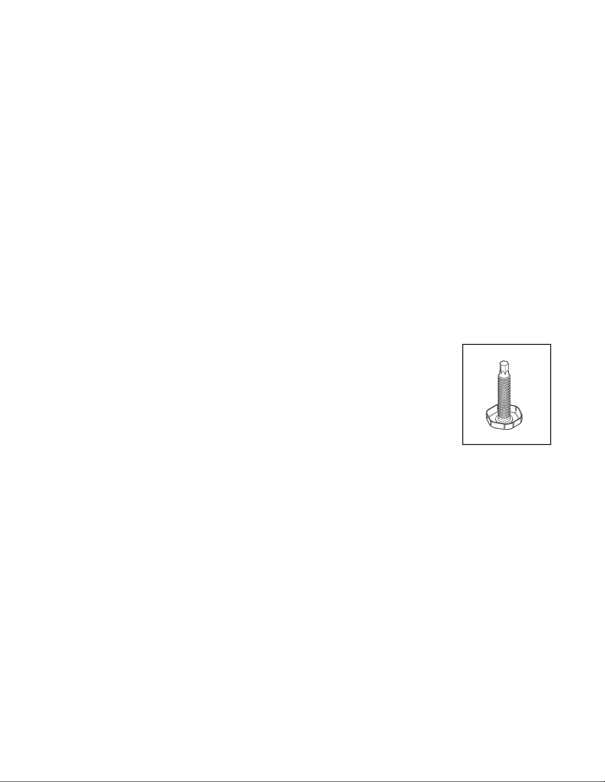
■ Before moving your refrigerator/beer dispenser into its position, ensure that the
adjustable front feet are fully retracted.
■ Position your refrigerator/beer dispenser. Turn to lower the front leveling leg. Raise the
front of the appliance until it is stable and doors move towards the closed position, on
their own, when open.
■ The front leveling leg on the hinge side should take the majorit y of the weight of the
cabinet and the cabinet should be stable, i.e. cabinet should not rock or wobble.
BEFORE PLACING FOOD IN THE FRESH FOOD COMPARTMENTS
■ Remove all packaging. Ensure that all transit tape is removed from the refrigerator.
■ Clean the inside of the appliance with warm water and a little liquid detergent to remove manufac turing and
transportation dust.
■ Allow the refrigerator/beer dispenser to run empty for 2 - 3 hours to allow each compar tment to cool to the
appropriate temperature.
■ The appliance may have an odor on its initial operation, but this will go away when the refrigerator/beer
dispenser have cooled sufficiently.
Fig. 01 LEVELING LEG
4
Page 7
INSTALLATION
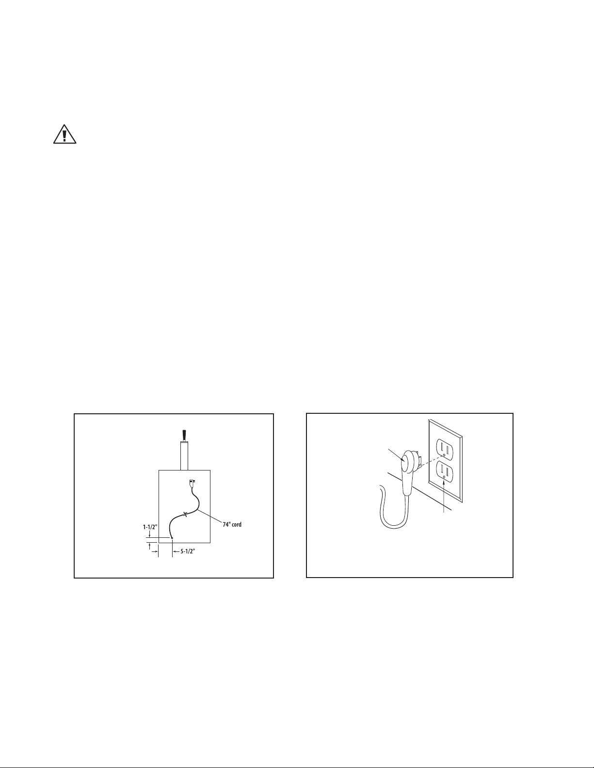
Grounding Type
Wall Receptacle
Power Supply Cord
with 3-Prong
Grounding
Plug
HOW TO INSTALL YOUR OUTDOOR REFRIGERATOR/BEER DISPENSER
ELECTRICAL CONNECTION:
Check serial plate for correct power supply. Use only electrical power supply as specified on your appliance
serial nameplate. Do not use an extension cord!
WARNING!
Do not splash or spray water from a hose onto the refrigerator! Doing so may cause an electrical shock, which may
result in severe injury or death.
GROUNDING METHOD
This product is factory equipped with a power supply cord that has a three -pronged grounded plug. I t must be
plugged into a mating grounding type receptacle in accordance with the National Electrical Code and applicable
local codes and ordinances. If the circuit does not have a grounding type receptacle, it is the responsibility and
obligation of the customer to exchange the existing receptacle in accordance with the National Electrical Code
and applicable local codes and ordinances. The third ground prong should not, under any circumstances, be cut
or removed. All UL listed refrigerated produc ts are equipped with this type of plug.
A ground fault circuit inter rupter (GFI) electrical receptacle is to be used to supply electrical power to the refrigerator for outdoor applications. Contact an electrician if you need to install one to supply electrical power to
your outdoor refr igerator.
POWER REQUIREMENTS:
■ 120V 60Hz
■ 1800 watt
■ 3 wire outlet
■ 15 amp circuit
AC Interface
Fig. 02
Note:
The plug shown is for 120V units.
Fig. 03
5
Page 8
INSTALLATION
13-3/4”
HOW TO INSTALL YOUR OUTDOOR REFRIGERATOR/BEER DISPENSER
SELECT LOCATION:
The proper location will ensure peak per formance of your appliance. Choose a location where the unit will be
out of direct sunlight, away from heat sources and moisture. Units with fan cooled condensers can be built in.
Unit should be operated in a properly ventilated area with ambient temperatures above 40 degrees and below
100 degrees Fahrenheit.
Installation should be such that the cabinet can be moved for servicing if necessary.
CABINET CLEARANCE:
Ventilation is required from the bottom front sec tion of the unit. Keep this area open and clear of any
obstructions.
The adjacent cabinets and counter top can be built around the unit as long as no top trim or counter top is
installed lower than the top of the hinge.
SIDE TRIM INSTALLATION:
Attach side tr im to the inner side of the cabinet so that the trim faces out ward (away from the appliance’s door)
and fasten with appropriate screws suitable for the type of cabinet material.
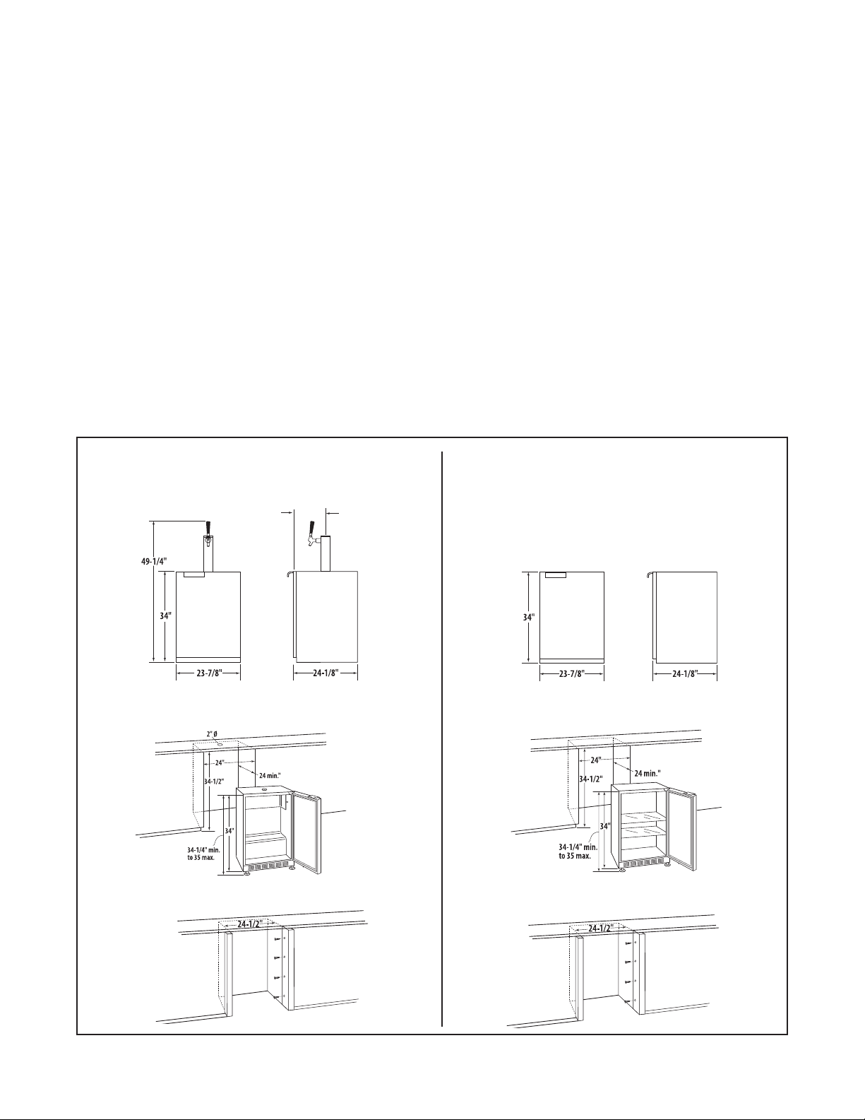
24” Outdoor Beer Dispenser
Dimensions
Island Preparation with No Side Trim
24” Outdoor Refrigerator
Dimensions
Island Preparation with No Side Trim
Island Preparation with Side Trim Installation
Mounting
screws not
provided
Island Preparation with Side Trim Installation
Mounting
screws not
provided
Fig. 04
6
Page 9

INSTALLATION
1-5/8”
2-5/8”
2-5/8”
11-3/4”
12”
HOW TO INSTALL YOUR OUTDOOR REFRIGERATOR/BEER DISPENSER
ISLAND BEER DISPENSER INSTALLATION:
When installing the Beer Dispenser under a counter and using a remote location for the Dispenser Tower, follow
instructions below. Steps need to be taken to insure proper temperatures are maintained in the dispenser.
IMPORTANT:
All holes must be sealed to prevent air leak. Placement of the tower can be done by cutting a hole in the counter top
directly above the existing hole of the Beer Dispenser unit (refer to tower template for dimensions Fig. 05).
1. Drill a 1-5/8” hole drilled thru the counter direc tly above the hole in the dispenser cabinet. Use the dimensions
shown to align both holes. When properly placed, you will see thru both holes.
2. Drill four 1/8” pilot holes at 2-5/8” apar t using the large hole as a center point (see Fig. 05).
3. Using some insulating foam rubber (not included), slide it over the beer line far enough to bring the hose up
thru the top of the cabinet and counter.
4. Connect the beer line assembly to the tower as per “Assemble and Connect Parts” on page 10.
5. Slide the insulating foam rubber into the hole in top of the dispenser, making an air tight seal.
6. Mount the tower to the top of the cabinet and fasten securely.
7. Make connections to the keg and CO2cylinder as per “Assemble and Connec t Par ts” on page 10.
NOTE:
When there is a large build up of frost or ice on the evaporator plate, the drip pan may not be large enough to retain all
of the melted ice. The evaporator plate should never have more than 1/8” of frost at any time.
Fig. 05
7
Page 10

INSTALLATION
HOW TO INSTALL YOUR OUTDOOR BEER DISPENSER COMPONENTS
Contents of Kit:
Draft Tower Assembly
Keg Coupler
Air Line with Clamps
Single Gauge Regulator
5 lb. CO2Empty Cylinder
Tools needed:
Crescent Wrench
Pliers
Screwdriver
Q. WHAT SIZE KEG WILL FIT INTO MY REFRIGERATOR?
Approximate measurements required to tap most kegs:
Quarter Barrel Half Barrel
Height 17-21 inches 25-29 inches
Diameter 16-20 inches 18-22 inches
Weight 80-85 pounds 160-180 pounds
Check with your local beer wholesaler or retailer to verify actual keg sizes, including tap heights.
Q. CAN MY REFRIGERATOR MAINTAIN TEMPERATURES BETWEEN 34º-38º F?
Draft beer is not pasteurized, so it must be kept cold, preferably 38º. Temperature above 38º may cause the beer
to become wild, turn sour and cloudy.
Draft beer should be consumed within 30-45 days. It is not pasteurized, and will lose its original brewer y fresh
taste and aroma the older it gets.
Q. HOW MUCH BEER WILL I CONSUME IN A 30 DAY PERIOD?
There are two keg sizes: the quar ter barrel containing 7-3/4 gallons or approximately 3-1/2 cases of 12 ounce
bottles or cans; the half bar rel containing 15-1/2 gallons or approximately 7 cases.
8
Page 11

INSTALLATION
HOW TO INSTALL YOUR OUTDOOR BEER DISPENSER COMPONENTS
WARNING!
CO
can be dangerous.
2
1. ALWAYS connec t CO2gas cylinder to reducing valve or re gualtor.
2. NEVER conn ect gas cylinder direc tly to keg.
3. ALWAYS secure gas cylinder in u pright position.
4. ALWAYS keep gas cylinder away from heat.
5. NEVER drop or throw g as cylinder.
6. ALWAYS ventilate after CO2leakag e.
If it becomes difficult to breathe and your head starts to ache, abnormal concentrations of carbon dioxide may be
present inthe area. Leave the room immdiately.
Gas cylinder should be stored in the coolest part of the stablishment, preferably at 70ºF.
Draft tower assembly
Beer line
Keg coupler
Air
line
Low pressure
gauge
Regular
Shut off
valve
CO2tank
Regulator coupling nut
Drum valve
Set screw
9
Page 12

INSTALLATION
HOW TO INSTALL YOUR OUTDOOR BEER DISPENSER COMPONENTS
ASSEMBLE AND CONNECT PARTS
1 . Screw the black faucet k nob onto the faucet
(Fig. 06).
2. Mount the draft tower onto the counter top using
the four furnished screws and the one mounting
gasket (Fig. 07).
3. Attach the elbow to the top of the keg coupler,
making sure to use a black washer
(Fig. 08).
4. Attach the beverage line coming from the draft
tower to the elbow. Use the black washer inside the
hex nut and tighten the beverage line securely with
a crescent wrench (Fig. 09).
5. Fasten the CO2regulator to the CO2cylinder,
tightening the CO2nut securely. Do not over
tighten; over tightening may damage the washer in
the stem of the regulator (Fig. 10. Ensure valve is
off.
Fig. 06
Fig. 07
6. Attach one end of the red air hose to the hose barb
on the CO
clamps provided (Fig. 11). Use pliers to snap the
clamp tight to assure that there is no gas leak.
7. Place the CO2cylinder and regulator inside one of
the corners of the refrigerator. It is important that
the cylinder be kept in an upright position to
operate efficiently, using a clain or heavy cord if a
wire rack is not provided (Fig. 12).
8. Fasten the other end of the red air line to the keg
coupler using the remaining snap clamp (Fig. 13).
regulator, using one of the two snap
2
Fig. 08
Fig. 10
Fig. 12
Fig. 09
Fig. 11
Fig. 13
10
Page 13

INSTALLATION
HOW TO INSTALL YOUR OUTDOOR BEER DISPENSER COMPONENTS
PARTS OF A CO2REGULATOR
1. Pressure gauge (reads the amount of internal keg pressure).
2. Regulator adjustment screw (after keg is tapped, screw clockwise until
pressure gauge indicates between 12 and 14 lbs.).
3. Adjustment lock nut (once the pressure gauge is between 12 and 14
lbs., tighten adjustment nut.)
4. Shut-off valve.
1
2
5
5. CO2nut (use to connect to the tank).
HOW TO REPLACE AN EMPTY CO2CYLINDER
1. Close shut-off valve “B”.
2. Close cylinder valve by turning clockwise “A”.
3. Remove regulator from empty cylinder “D”.
4. Remove dust cap from new c ylinder at “D”.
5. With cylinder valve “A” in closed position, reattach regulator to cylinder
at “D”. (Check condition of gasket/o-ring).
6. Open valve “A” all the way. ( This is important because the cylinder
valve seals in two places.)
7. Open shut-off valve “B”.
8. Check gauge pressure “C” (12-14 lbs.) and adjust if necessary.
CO2CYLINDERS (It is recommended to have an extra
cylinder on hand)
Cylinder Dia. Ht. Empty Weight Full Weight
1-1/2 lbs. 3-1/2” 18-1/4” 6-1/2 lbs. 9 lbs.
3
4
Fig. 14
C
A
D
CLOSED
OPEN
B
5 lbs. (provided) 5” 17-1/2” 12-1/2 lbs. 17-1/2 lbs.
Note:
It takes about 1/2 lb. of CO2to dispense an 1/2 barrel of beer. A 2-1/2 lb. CO
cylinder should dispense between 4 to 5-1/2 barrels or 8 to 10-1/4 barrels.
A 5 lb. CO2cylinder should dispense between 8 to 10-1/2 barrels or 18 to
20-1/4 barrels.
11
Fig. 15
2
2-1/2 lbs.
Fig. 16
5 lbs.
Page 14

INSTALLATION
TAPPING PROCEDURES
LEVER TYPE KEG COUPLER
(Taps most major domestic brands)
1. Align lug locks on tap head
with lug housing in top of
keg; inser t tap head.
OPTIONAL WING TYPE KEG COUPLER
(Taps most major domestic brands)
2. Turn tap head handle 1/4
1. Align lug locks on tap head
with lug housing in top of
keg; inser t tap head.
turn clock wise; the tap
head is now secured to
the keg.
2. Turn tap head handle 1/4
turn clock wise; the tap
head is now secured to
the keg.
3. Pull tap handle out and
push down to open beer
and CO2ports in the keg.
The keg is now tapped.
3. Rotate on/off valve handle
1/4 turn clockwise to open
beer and CO2ports in the
keg. The keg is now tapped.
12
Page 15

USING THE BEER DISPENSER
O
F
F
7
6
5
4
3
2
1
C
O
L
D
E
R
TEMPERATURE CONTROL
Initially set the cold control k nob midway between the numbers.
After at least 2 hours, adjust to the temperature that suits you. The
higher the number you select, the cooler the temperature (Fig. 17).
The temperature control knob is located at the bottom front of the
cabinet, just behind the square opening near the middle of the
venting grill.
DEFROSTING INSTRUCTIONS (IF NEEDED)
Never use a scraper or any tool that might scratch or pierce the
cooling plate. Follow these steps whenever 1/4 inch or more of
frost accumulates:
1. Disconnect the power cord and set the cold control knob to “OFF”
position.
2. Remove contents.
3. Place pans of hot water on the shelf under cooling plate if you wish to speed up defrosting.
Note:
Place a clean cloth under the hot pan of water to protect the glass shelf from breaking.
Fig. 17
4. Wipe out the interior and replace contents.
5. Connect power cord to outlet.
6. Set temperature control to desired level.
HELP PREVENT TRAGEDIES. . .
Each year children die because they climb inside a discarded refrigeration product, get trapped inside and
suffocate. Take precautions to prevent such tragedies by removing the door, taping or chaining it shut before
discarding.
ALL REFRIGERATOR MODELS
All refrig erator models automatically defrost their cooling plate during e ach compressor off c ycle. No
manual defrosting is required.
13
Page 16

USING THE REFRIGERATOR CONTROL
Door Switch
NOTE
During initial startup, or anytime power is interrupted, there
will be an approximate 5 minute delay before the refrigerator
starts. During this period the controller will be assessing the
temperature in the refrigerator and the display will appear erratic, this is normal. The desired temperature set point can be
programmed during this start up period.
Starting your refrigerator
The refrigerator will begin start up when initially plugged in
or when power resumes after a power outage. At this time the
refrigerator will take approximately 5 minutes to begin running
as noted above. If the refrigerator has been turned o during
use, “OFF” will appear on the display. To start the refrigerator
from the “OFF” position press and hold the ON/OFF button for
three seconds.
Set temperature
To set temperature set point, press and continue to hold “SET”
button. After one second, set point will be displayed. While
holding “SET” button use the “WARMER” or “COLDER” button to
desired set point.
NOTE: Momentarily pressing & releasing “SET” button will access information menu of control. Refer to page 15 for information on this feature.
Refrigerator operation
The available temperature range of the refrigerator is 33° to 45°
(1° to 7° C). It may take up to 24 hours for your refrigerator to
reach desired temperature. This will depend on amount of contents loaded and number of openings and closings of the door.
For best results allow refrigerator to “pull down” to desired set
point before loading. Once contents are loaded, allow at least
48 hours for temperature to stabilize before making any adjustments to the set point.
Alarms
Your refrigerator control will monitor refrigerator function and
alert you with a series of audible and visual alarms.
tDoor Ajar Alarm: If the door has been left
open for over ve (5) minutes, the alarm
will sound in one (1) second intervals. The
display panel will ash “do” and the LED light will be a steady
amber color. This will stop as soon as the door is closed.
tHigh and Low Temperature Alarm: If your
unit reaches an unacceptable temperature
outside of your set point, the alarm will
sound in one (1) second intervals. The
display panel will ash either “hi” or “Lo”
depending upon the condition and the LED light will be a
steady amber color. “hi” indicates that the temperature is 10° F
(5.5°C) above the set point and “Lo” indicates that the temperature is 10° F (5.5°C) below the set point. The alarm will remain
active until the condition is corrected.
NOTE: During initial appliance start-up, the high temperature
alarm may sound until the interior temperature reaches set
point.
tTemperature Sensor Fault: If the controller
detects that the temperature sensor is
not properly functioning, a temperature
sensor alarm will sound. “E1” will ash on the display, and an
alarm will sound. Please call Customer Service or
your dealer if this error code is displayed.
tCondenser Needs Cleaning:
When the refrigerator has reached the
recommended amount of run time to necessitate cleaning the air ow, “cL” will ash on the display as a
reminder. See the “Care and Cleaning” section for cleaning
instructions.
To clear the alarm:
1) Press and release the “SET button four times.
“cnd” will be displayed on the screen.
2) While “cnd” is displayed, press and hold the “SET” but ton. The display will show the number of weeks the
refrigerator has been running.
3) While holding the “SET” button, press and release the
ON/OFF button. The number shown on the display will
reset to 0.
4) Release the “SET” key.
Alarm Mute
Press any key to mute the audible portion of an alarm,.
NOTE-This action will only mute the alarm. If the condition that
caused the alarm continues, the alarm code will continue to
ash and will sound for 20 seconds every 60 minutes.
Turning Refrigerator O
To turn refrigerator o, press and hold “ON/OFF” button for
three (3) seconds. “OFF” will appear on the display.
Additional Features
Refer to page 15 for details on additional features available.
14
Control
Figure 3
Page 17

ADDITIONAL REFRIGERATOR CONTROL FEATURES
Information Menu:
The following features are available on the Information Menu.
t$VSSFOU5FNQFSBUVSF
t.BYJNVN4UPSFE5FNQFSBUVSF
t.JOJNVN4UPSFE5FNQFSBUVSF
t5PUBM0QFSBUJOH5JNF0G5IF$POEFOTFS
t,FZQBE-PDLPVU
To access the Information Menu Press “SET” button momentarily and release.
Once in the information menu, the WARMER and COLDER keys
may be used to scroll through the information menu. Additionally, pressing and releasing the SET key will advance the
information menu.
The information menu will automatically exit after several seconds with no key presses.
Current Interior Temperature (tI): Press and
hold the “SET” key to display the current inte rior temperature.
Maximum Stored Temperature (thi): Maxi mum stored temperature is the maximum
temperature refrigerator has achieved since
temperature set point was entered. Press and hold the “SET”
key to display the maximum temperature stored. The data
can be cleared by pressing “SET” and “ON/OFF” simultaneously
while the value is displayed. NOTE: It is normal for refrigerator
temperature to uctuate from set point by several degrees.
Keypad Lockout Feature (Loc): This feature
is useful for prohibiting changes in the
temperature set point or accidentally turning
the unit o. Press and hold the “SET” key to display the cur-
rent “Loc” setting. If “No” is displayed, Lock
out is OFF and all keys are enabled. If “Yes”
is displayed, Lockout is ON and the “ON/OFF”, “WARMER”, and
“COLDER” keys are disabled. However, the key tones remain
enabled. While holding the “SET” key, press the “WARMER” or
“COLDER” key to select the desired state. Release the “SET” key
to conrm the selection.
NOTE: The Information/Lockout Key “SET” remains enabled
regardless of the “Loc” setting.
Minimum Stored Temperature (tLO): Mini mum stored temperature is the minimum
temperature refrigerator has achieved since
temperature set point was entered. Press and hold the “SET” key
to display the minimum temperature stored. The data can be
cleared by pressing “SET” and “ON/OFF” simultaneously while
the value is displayed. NOTE: It is normal for refrigerator temperature to uctuate from set point by several degrees.
Total Operating Time of the Condenser Since
the Last Cleaning (cnd): Press and hold the
“SET” key to display the total operating hours
of the compressor since the last cleaning. The control stores
the total operating hours of the compressor to determine the
volume of air that has moved across the condenser coils. This
number is displayed in weeks. A reminder is displayed when a
cleaning is recommended (see Alarm Codes). The recommended cleaning period is the equivalent of one year of air volume.
The data can be cleared by pressing the “SET” and “ON/OFF”
keys simultaneously while the value is displayed
15
Page 18

USING THE REFRIGERATOR/BEER DISPENSER
DR AW A GLASS OF BEER
1. Star t with a clean beer
glass that has been
wetted in cold water.
Place the glass at a
45º angle, one inch
below the faucet. Do
not let the glass touch
the faucet. Open the
faucet all the way.
2. After the glass has
GLASS OF BEER
reached half full,
gradually bring the
glass to an upright
position.
3. Let the remaining
beer run straight
down the middle.
This insures proper
release of CO2by
producing a 3/4” to
1” foam head.
4. Close the faucet
completely and
quick ly.
DRAW A
16
Page 19

CARE AND MAINTENANCE
HOW TO CLEAN AND MAINTAIN YOUR UNIT
Condenser
The condenser coil under the cabinet for forced air unit does require frequent cleaning. Satisfactor y cooling
depends on adequate ventilation over the condenser coil. Be sure that nothing obstructs the air flow openings
in the lower front of the cabinet.
Cabinet
The stainless steel cabinet can be washed with mild soap and water and thoroughly rinsed with clear water.
Never use abrasive scouring powders.
Interior
It is important to keep the interior of the refrigerator/beer dispenser clean to help prevent food from becoming
contaminated dur ing storage. The amount and types of food stored determines how of ten cleaning should be
carried out (ideally once every 1 or 2 weeks) in the refrigerator. Remove the shelves from cabinet and door. Wash
shelves and storage bins in warm water and detergent; rinse in clean water and dr y before replacing. Wash
interior compartment with mild soap and water. Wipe over the interior sur faces with warm water and detergent
or baking soda dissolved in warm water (add 1 teaspoon of baking soda to each 1 pint [500 ml] of water). Do
not use an abrasive powder, solvent, polish cleaner, abrasive cloths, highly perfumed, strong smelling cleaners or
undiluted detergent on any par t of the refrigerator or beer dispenser. Rinse with clean water. To help remove “old
stale refrigerator” smells, add a few drops of vanilla essence or vinegar to the water before cleaning.
Ex terior – Stainless Exterior Door
It is important when cleaning the ex terior door surface of your refrigerator or beer dispenser, to only use liquid
dishwashing detergent, dissolved in warm water. Dr y the door with a clean, lint-free cloth. The use of any
abrasive or stainless steel cleaners and solvents will damage the door surface.
Other Ex terior Sur faces and Door Gasket
Clean all other exterior surfaces with warm water and detergent. If necessary, clean the magnetic door gasket
with an old toothbrush, warm water and detergent.
Interior – Glass Shelves
Clean with warm water and detergent or a glass cleaner. If cleaning the shelves without removing from the
cabinet, use only warm water and detergent as a glass cleaner can damage the plastic components of your
refrigerator/beer dispenser.
Important Note:
Many commercially available cleaning products contain solvents that may attack the plastic components of your
refrigerator and cause them to crack. It is important to use only warm water and a small amount of liquid dishwashing
detergent on any plastic components inside and outside your refrigerator. Avoid using anti-bacterial cleaning products
on either the interior or exterior of the cabinet as they may cause rusting of metal components and cracking of plastic
components.
17
Page 20

CARE AND MAINTENANCE
REPLACE INTERIOR LIGHT BULB
When supplied with an inter ior light, your refrigerator uses a 15 Watt appliance light bulb. To replace the light
bulb, proceed as follows:
1. Unplug the power cord from the power supply.
2. Open the cabinet door, the light bulb is located behind the display housing at the top of the unit.
3. Unscrew the existing bulb and replace with an equivalent 15 Watt, threaded, intermediate base appliance bulb.
Do not replace with a bulb higher than 15 Watts.
THINGS TO REMEMBER. . .
1. Allow 24 hours for your refrigerator to reach a new temperature setting.
2. The motor will start and stop of ten. It must do this to maintain the temperature you selec t.
3. Keep your refrigerator reasonably level.
4. Unplug the refrigerator before work ing on anything with the electrical system.
5. Exercise caution when sweeping, vacuuming, or mopping near the front of the unit. Damage to the grill and/or
the light fixture switch can occur.
6. For all cleaning of the refrigerator interior, mix 2 tablespoons bak ing soda with 1 quar t warm water or use mild
soap. Do not use strong cleaners or scouring powder or pads.
7. Keep your refrigerator out of direct sunlight.
8. Do not splash or spray water on or under the refrigerator.
9. Clean your refrigerator ’s condenser periodically to maintain proper cooling per formance.
ENERGY SAVING TIPS
1. Reduce door openings.
2. Close the door as soon as you can.
3. Keep the coils on bottom of the refrigerator clean.
4. Adjust the temperature control to a warmer setting when practical.
5. Don’t put hot foods in the refrigerator.
6. Keep unit away from the stove or other heat sources.
18
Page 21

MOVING OR STORING YOUR REFRIGERATOR
If your refrigerator or beer dispenser is turned off for any reason, wait 10 minutes before turning it back on. This
will allow the refrigeration system pressures to equalize before restarting.
MOVING YOUR REFRIGERATOR OR BEER DISPENSER
■ Turn off the appliance and unplug from the power point. Remove all food.
■ Turn the leveling legs in as far as they will turn (see page 4, Stability).
■ Ease the refrigerator out of its position. Tuck the power cord away and tape the doors closed. Tape the shelves
in place. If the cabinet needs to be placed at an angle or laid down, carefully lay it on its side (the right hand
side when viewed from the front).
■ Relocate and install. If the appliance has been left on its side for any length of time, leave it standing upright
for at least 12 hours before turning on.
STORING YOUR REFRIGERATOR OR BEER DISPENSER
■ When storing your cleaned appliance, leave the door open. This allows air to circulate and prevents the
build up of bacteria and molds.
■ Before using again, clean well using a mixture of warm water and bak ing soda (add 1 teaspoon of baking soda
to each 1 pint [500 ml] of water). Rinse with clean water.
VACATION TIME
■ We recommend you leave your refrigerator/beer dispenser operating while you are on vacation. It will prevent
mold and odors from building up.
CAUTION!
Never transport a refrigerator on it back or side for any distance. This may damage the cooling components.
19
Page 22

TROUBLESHOOTING
PROBLEM POSSIBLE CAUSE/SOLUTIONS
ODOR IN CABINET Interior needs cleaning
NOISY OPERATION
CABINET VIBRATES
CABINET LIGHT NOT WORKING
(OPTIONAL FEATURE)
APPLIANCE WILL NOT RUN
APPLIANCE RUNS TOO LONG
MOISTURE COLLECTS INSIDE
MOISTURE COLLECTS ON OUTSIDE SURFACE
Cabinet not level
Fan blade damaged. Call for service
Cabinet not level
Fan blade damaged. Call for service
Bulb burned out
Open door switch. Call for service
Temperature control turned to “OFF”
Line cord not plugged in
No power at electrical outlet
House fuse blown
Prolonged door openings
Control set too cold
Condenser needs cleaning
Too many door openings
Prolonged door openings
Hot, humid weather increases condensation
Hot, humid weather increases condensation. As humidity
decreases, moisture will disappear.
Control improperly set
INTERIOR TOO HOT/TOO COLD
Control improperly set
Faulty thermometer
Condenser needs cleaning
Air leaking into unit
20
Page 23

TROUBLESHOOTING
COMMON DRAFT PROBLEM
PROBLEM DESCRIPTION CAUSES
Beer drown improperly
Creeping regulator
Applied pressure is set too high
WILD BEER
CLOUDY BEER
FLAT BEER
Beer, when drawn, is all
foam, or too much foam
and not enough liquid
beer.
When beer in glass
appears haz y, not clear.
Foamy head disappears
quick ly ; beer lacks usual
zestful brewery fresh
flavor.
Hot spots in line
Use of non-insulated beer line
Beer runs are too long for proper cooling
Tapped into a warm keg (should be 34º-38º)
Cooler malfunctioning
Kinks, dents, twists or other obstructions in line
Faucets in bad, dirty or worn condition
Frozen or nearly frozen beer
Old beer
Beer that as been unrefrigerated for long periods of time
Dirty glass
Dirty faucet
Unrefrigerated foods placed on top of cold keg
Contaminated air source.
Dirty glasses (not beer clean)
Sluggish regulator
Applied pressure isset too low
CO2is tur ned off at night
Contaminated air source (associated with compressed air)
FALSE HEAD
UNPALATABLE
BEER
Large soap -like bubbles,
head dissolves ver y
quick ly
Off-taste
Moisture in air system
Beer too cold
Loose tap or vent connections
Applied pressure required does not correspond to beer
temperture
Small beer line into a large faucet shank
Beer lines warmer than beer in keg
Dr y glasses
Improper pour
Dirty or old beer lines
Dirty faucet
Contaminated air source, or unfiltered
Unsanitar y bar conditions
21
Page 24

SERVICE
HOW TO OBTAIN SERVICE:
For warranty service, please contact your local service provider or DCS Customer Care at (888) 936-7872. Before
you call, please have the following infor mation ready :
■ Model Number (the serial plate is located on the upper left side, inner wall).
■ Serial Number (the serial plate is located on the upper lef t side, inner wall).
■ Code (the serial plate is located on the upper left side, inner wall).
■ Date of installation
■ A brief description of the problem
Your satisfac tion is of the utmost importance to us. If a problem cannot be resolved to your satisfaction, please
write or email us at:
Write:
Fisher & Paykel Appliances, Inc.
Attention: DCS Customer Care
5900 Skylab Road
Huntington Beach, CA 92647
Email:
customer.care@fisherpaykel.com
BEFORE YOU CALL FOR SERVICE:
Check troubleshooting on page 18.
22
Page 25

WARRANTY
LIMITED WARRANTY
When you purchase any new DCS Refrigeration Produc t, you automatically receive a One Year Limited Warranty
covering parts and labor for servicing within the 48 mainland United States, Hawaii, Washington, D.C. and
Canada. In Alaska the Limited Warrant y is the same except that you must pay to ship the Product to the ser vice
shop or for the service technician’s travel to your home. Products for use in Canada must be purchased through
the authorized Canadian distribution channel to ensure regulatory compliance.
You receive an additional Four Year Limited War ranty (for a total of Five Years) covering parts for the sealed
refrigeration system (compressor, evaporator, condenser, filter dr yer, and connec ting tubing) within the 48
mainland United States, Hawaii, Washington, D.C. and Canada. In Alaska the Limited Warranty for the sealed
refrigeration system is the same except that you must pay to ship the Product to the ser vice shop or the ser vice
technician’s travel to your home.
FISHER &PAYKEL UNDERTAKES TO:
Repair without cost to the owner either for material or labor any part of the Product, the serial number of which
appears on the Product, which is found to be defective. In Alaska, you must pay to ship the Product to the
service shop or for the service technician’s travel to your home.
If we are unable to repair a defec tive part of the Produc t after a reasonable number of attempts, at our option
we may replace the part or the Produc t, or we may provide you a full refund of the purchase price of the Product
(not including installation or other charges).
This warranty extends to the original purchaser and any succeeding owner of the Product for products
purchased for ordinar y single-family home use.
All ser vice under this Limited Warranty shall be provided by Fisher & Paykel Appliances Inc. or its Authorize d DCS
Service Agent during normal business hours.
LIMITED WARRANTY
How Long Does this Limited Warranty Last?
Our liability under this Limited Warranty expires One Year from the date of purchase of the Product by the first
consumer.
Our liability for repair of defects in any sealed refrigeration system (compressor, evaporator, condenser, filter
dr yer, and connecting tubing) extends an additional Four Years, for a total of Five Years from the date of
purchase of the Product by the first consumer.
Our liability under any implied warranties, including the implied warranty of merchantability (an unwritten
warranty that the Product is fit for ordinar y use) also expires One Year (or such longer period as required by
applicable law) from the date of purchase of the Product by the first consumer. Some states do not allow
limitations on how long an implied warranty lasts, so this limit on implied warranties may not app ly to you.
THIS WARRANTY DOES NOT COVER
A. Ser vice calls that are not related to any defect in the Product. The cost of a ser vice call will be charged if the
problem is not found to be a defect of the Product. For example:
1. Correc t faulty installation of the Produc t.
2. Instruct you how to use the Product.
3. Replace house fuses, reset circuit breakers, correc t house wiring or plumbing, or replace light bulbs.
4. Correc t fault(s) caused by the user.
5. Change the set-up of the Product.
6. Unauthorized modifications of the Product.
23
Page 26

WARRANTY
7. Noise and vibration that is considered normal e.g. drain sounds, regeneration noises and user warning beeps.
8. Correc ting damage caused by pests e.g. rats, cockroaches etc.
9. Used in commercial applications.
B. Defec ts caused by factors other than:
1. Nor mal domestic use or
2. Use in accordance with the Product’s Use and Care Guide.
C. Defects to the Product caused by accident, neglect, misuses, fire, flood or Act of God.
D. The cost of repairs carried out by non-authorized repairers or the cost of correcting such unauthorized repairs.
E. Travel Fees and associated charges incurred when the product is installed in a location with limited or restricted
access.(i.e. airplane flights, ferr y charges, isolated geographic areas).
F. Normal recommended maintenance as set for th in the Product’s Use and Care Guide.
If you have an installation problem contact your dealer or installer. You are responsible for providing adequate
electrical, exhausting and other connec tion facilities.
We are not responsible for consequential or incidental damages (the cost of repairing or replacing other
property damaged if the Product is defective or any of your expenses caused if the Product is defec tive). Some
states do not allow the exclusion or limitation of incidental or consequential damages, so the above limitation or
exclusion may not apply to you.
HOW TO GET SERVICE
Please read this Use and Care Guide. If you then have any questions about operating the Product, need the name
of your local DCS Authorized Ser vice Agent, or believe the Product is defective and wish service under this
Limited Warranty, please contact your dealer or call us at:
TOLL FREE 1-888-936-7872 or contact us through our web site: www.dcsappliances.com
You may be required to provide reasonable proof of the date of purchase of the Product before the Product will
be ser viced under this Limited Warranty.
COMMERCIAL USE
This warranty applies to appliances used in residential applications; it does not cover their use in commercial
situations.
NO OTHER WARRANTIES
This Limited Warranty is the complete and exclusive agreement between you and Fisher & Paykel Appliances Inc.
regarding any defect in the Product. None of our employees (or our Authorized Service Agents) are authorized to
make any addition or modification to this Limited War ranty.
Warrantor: Fisher & Paykel Appliances, Inc.
If you need further help concer ning this Limited Warranty, please call us at the above number, or write to:
Fisher & Paykel Appliances, Inc.
5900 Skylab Road, Huntington Beach, CA 92647
This Limited Warranty gives you specific legal rights, and you may also have other rights which vary from state to
state.
Fisher & Paykel Appliances I nc. is a leading manufacturer of premium quality cook ing and specialty appliances
under the Fisher & Paykel and DCS brands.
24
 Loading...