

Page 1

燃气灶
Installation instructions
and User guide
CG604DW & CG905DW models
安装说明
安装说明
和用户指南
用户指南
CG604DW型和CG905DW型
Gas cooktops
HK SG
Page 2

Page 3

1
EN
Contents
Safety and warnings
2
Installation instructions
6
Introduction
16
Using your cooktop
17
Cooking guidelines and cookware
20
Care and cleaning
22
Troubleshooting
27
Warranty and service
29
Important!
SAVE THESE INSTRUCTIONS
The models shown in this document may not be available in all markets and are
subject to change at any time. For current details about model and specification
availability in your country, please visit our website listed on the back cover
or contact your local Fisher & Paykel dealer.
Page 4
2
EN
Installation
WARNING!
Cut Hazard
Beware of sharp edges when handling stainless steel appliances.
Failure to use caution could result in injury or cuts.
WARNING!
Electrical Shock Hazard
Before carrying out any work on the electrical section of the appliance, it must
be disconnected from the mains electricity supply.
Connection to a good earth wiring system is absolutely essential and
mandatory.
Alterations to the domestic wiring system must only be made by a quali ed
electrician.
Failure to follow this advice may result in electrical shock or death.
Safety and warnings
Page 5
3
EN
Important safety instructions!
Installation
Read these instructions carefully before installing or using this product.
Please make this information available to the person responsible for installing the product as it
could reduce your installation costs.
This appliance shall only be installed and serviced by an authorised person.
Incorrect installation, for which the manufacturer accepts no responsibility, may cause personal
injury or damage and could invalidate any warranty or liability claims.
This appliance must be installed in accordance with these installation instructions, local
gas fitting regulations, municipal building codes, water supply regulations, electrical wiring
regulations and any other relevant statutory regulations.
Do not modify this appliance.
Models without flame failure protection MUST NOT be installed in marine craft, caravans or
mobile homes.
When this appliance is installed, it shall not be used as a space heater.
No combustible materials or products should be placed on this appliance at any time.
Do not spray aerosols in the vicinity of this appliance while it is in operation.
This appliance should not be sealed into the bench with silicone or glue. Doing so will make
future servicing difficult. Fisher & Paykel will not be liable for costs associated with releasing such
a product, nor for repairing damage that may be incurred in doing this.
Packing elements (eg plastic bags, polystyrene foam, staples, packing straps etc) and tools
should not be left around during and after installation, especially if they are within easy reach of
children, as these may cause serious injuries.
Safety and warnings
Page 6
4
EN
Safety and warnings
WARNING!
WARNING!
Hot Surface Hazard
This appliance becomes hot during use.
Do not touch the cooktop components, burners, trivets, pan supports or the
base when hot.
Before cleaning, turn the burners o and make sure the whole cooktop is cool.
Failure to follow this advice may result in serious injury.
Fire Hazard
Never leave the appliance unattended when in use. Boilover causes smoking
and greasy spillovers that may ignite.
Never use your appliance for warming or heating the room.
Failure to follow this advice may result in serious injury.
WARNING!
Electrical Shock Hazard
Switch the power to the cooktop o at the wall before cleaning or
maintenance.
Failure to follow this advice may result in death or electrical shock.
WARNING!
Explosion Hazard
Models with no ame failure protection: If the ame is accidentally
extinguished, turn the control dials and gas supply valve o immediately
and thoroughly ventilate the room. Do not attempt to relight any burner
until you are certain that all gas that may have escaped has dispersed.
Do not use or store ammable materials such as gasoline near this
appliance. Do not spray aerosols in the vicinity of this appliance while it is in
operation.
Failure to follow this advice may result in death or serious injury.
Operation
Page 7

5
EN
Safety and warnings
Important safety instructions!
Operation
Keep children away from the cooktop when it is in use.
Household appliances are not intended to be played with by children.
Children, or persons with a disability which limits their ability to use the appliance, should have a
responsible person to instruct them in its use. The instructor should be satisfied that they can use
the appliance without danger to themselves or their surroundings.
If the electrical supply cord is damaged, it must only be replaced by an authorised person. Ensure
that the electrical connection plug is accessible after installation.
This appliance should be connected to a circuit that incorporates an isolating switch providing
full disconnection from the electricity supply.
Do not use an asbestos mat or decorative covers between the flame and the saucepan as this may
cause serious damage to your cooktop.
Do not place aluminium foil or plastic dishes on the cooktop burners.
Do not let large saucepans or frying pans overlap the bench as this can deflect heat onto your
benchtop and damage the surface.
Do not let large saucepans, frying pans or woks push any other pans aside. This could make them
unstable or deflect heat onto your benchtop and damage the surface.
Do not use a steam cleaner for cleaning this cooktop.
Saucepan handles may be hot to touch. Ensure saucepan handles do not overhang other gas
burners that are on. Keep handles out of reach of children.
Do not stand or place heavy objects on this appliance.
After use, ensure that the control dials are in the ‘OFF’ position.
This appliance shall not be used as a space heater, especially if installed in marine craft or
caravans.
The use of a gas cooking appliance results in the production of heat and moisture in the room
in which it is installed. Ensure the kitchen is well ventilated. Keep natural ventilation holes open
or install a mechanical ventilation device (mechanical extractor hood). Prolonged intensive use
of the appliance may call for additional ventilation, for example opening of a window, or more
effective ventilation, for example increasing the level of mechanical ventilation where present.
After having unpacked the appliance, check to ensure that it is not damaged.
In case of doubt, do not use it and consult your supplier or a professionally qualified technician.
Packing elements (eg plastic bags, polystyrene foam, nails, packing straps, etc.) should not be left
around within easy reach of children, as these may cause serious injuries.
Some appliances are supplied with a protective film on steel and aluminium parts. This film must
be removed before using the appliance.
Page 8
6
EN
Installation instructions
A
B
C
D
E
F
G
H
I
J
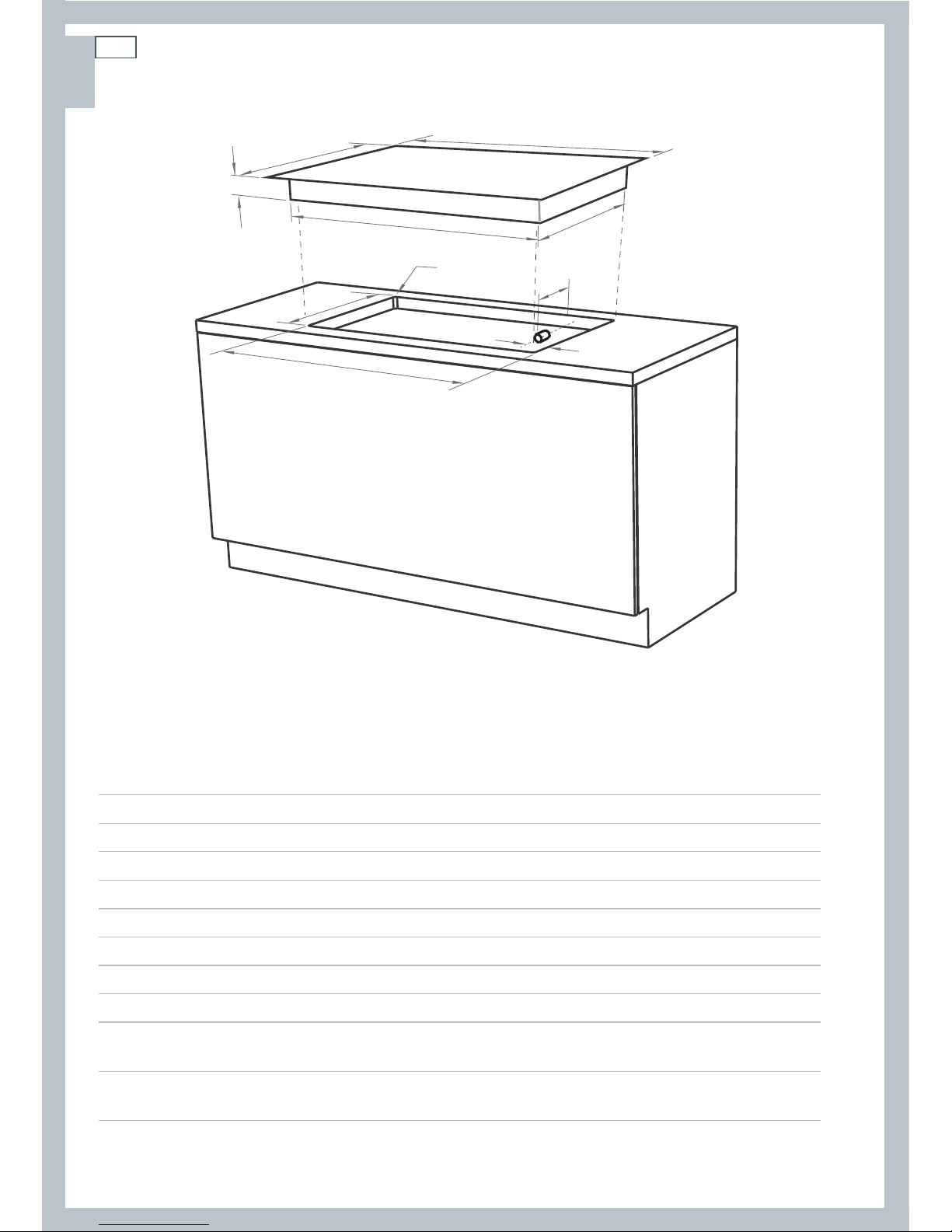
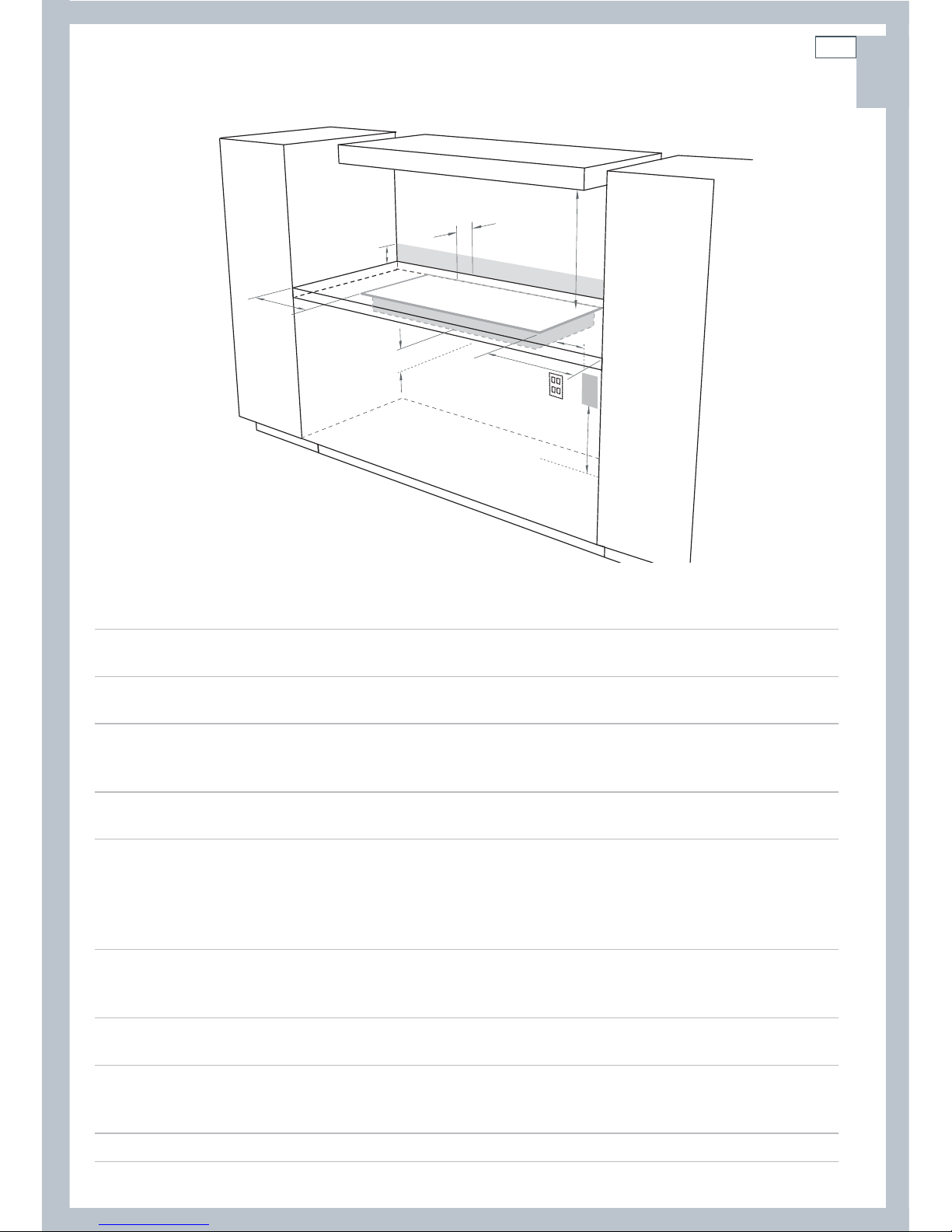
Cooktop and cutout dimensions (mm)
CG604
CG905
A
overall width of cooktop
578 914
B
overall depth of cooktop
511 533
C
height of chassis below top of bench
50 50
D
width of chassis
554 840
E
depth of chassis
480 480
F
overall width of cutout
560 870
G
overall depth of cutout
490 494
H
corner radius of cutout
max. 10 max. 10
I
distance from right edge of cutout to
manifold centre line
30 30
J
distance from rear edge of cutout
to gas inlet
40 47
Page 9
7
EN
Installation instructions
Clearances (mm)
CG604
CG905
A
minimum clearance from left edge of cutout to:
nearest combustible surface
140 140
B
minimum clearance from right edge of cutout to:
nearest combustible surface 140 140
C
minimum clearance from rear edge of cutout to:
nearest combustible surface
nearest non-combustible surface
110
20
110
30
D*
minimum height of non-combustible material when used on
adjacent walls 150 150
E
minimum clearance from pan supports to:
rangehood
any other overhead exhaust fan
downward-facing combustible surface (overhead cabinetry)
downward-facing tiled or re-resistant surface
650
800
650
500
650
800
650
500
F
minimum clearance below top of benchtop to:
nearest combustible surface
F&P oven or nearest non-combustible surface
60
60
60
60
G
Ensure there is an earthed power outlet within 900 mm of the rear right-hand corner of the
cooktop. The outlet should be accessible with the cooktop installed.
H
If connecting the cooktop to the gas supply with a exible hose, the connector on the wall
should be between 800-850 mm above the oor and to a distance of at least 250 mm outside
the width of the cooktop. The connector should be accessible with the cooktop installed.
* See section ‘Standards requirements’ following.
C
E
A
F
B
G
H
D
Page 10
8
EN
Installation instructions
Before you start
Before starting to install the cooktop, make sure that:
the cooktop has not been damaged during transport. In case of doubt after unpacking and
checking it, contact the retailer
the local distribution conditions (nature of gas and pressure) and the adjustment of the cooktop
(as detailed on the appliance data label and in the ‘Gas rate and injector size table’ further
below) are compatible
the cooktop will be connected to a 220-240 V 50 Hz power supply and earthed via the power
supply cable
there is an earthed power outlet within the reach of the cooktop’s power supply cable (within
900 mm from the rear right of the cooktop, see dimension G in ‘Clearances’)
the power outlet will be accessible after installation
the power supply cable will not touch any hot metal parts
a suitable isolating switch providing full disconnection from the mains power supply is
incorporated in the permanent wiring, mounted and positioned to comply with local wiring
rules and regulations. The isolating switch must be of an approved type and provide a 3 mm air
gap contact separation in all poles (or in all active [phase] conductors if the local wiring rules
allow for this variation of the requirements)
the isolating switch will be accessible after installation
the benchtop is made of a heat-resistant material
exposed bare edges of the cutout are sealed with an oil-based paint or moistureproof
polyurethane to prevent possible damage from moisture creeping between the cooktop trim
and the benchtop.
Page 11
9
EN
Installation instructions
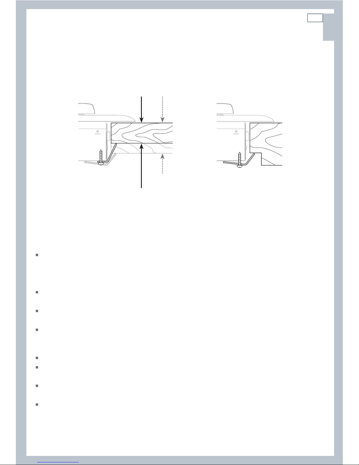
Fastening the cooktop to the bench
This cooktop is suppled with fastening brackets (and screws) that will cope with a
bench thickness of 20-50 mm. For benches thicker than 50 mm, recess the underside
to a thickness of 20-50 mm.
Connecting the cooktop to the gas supply
Important!
This cooktop is supplied factory-set for Town Gas, but is suitable for installation with either Town
Gas or LPG, provided the injectors appropriate for the gas type are installed. Refer to the ‘Gas
rate and injector size table’ for nominal ratings and appropriate injector sizes, and to section
‘Converting to a different gas type’.
The gas connection must be carried out by a suitably qualified person according to the relevant
standards.
For Town Gas, connect the gas supply to the gas pressure regulator supplied with the cooktop.
(Bromic; model BM-WF-1A). Ensure the gas supply is regulated to 8 mbar (3.2” W.C).
For LPG, connect the the gas supply to the test point adaptor supplied with the cooktop.
Ensure that the supply pressure is regulated to 27.5 mbar (11” W.C.) See section ‘Converting to a
different gas type’.
Make sure the connection point will be accessible with the cooktop installed.
To enable the gas supply to be readily shut off, make sure the connection is fitted with an
isolating valve close to the cooktop.
Attach the duplicate appliance data label on a surface adjacent to the cooktop, so that it will be
easily read with the cooktop installed.
For instructions on converting the cooktop for use with a different gas type, see section
‘Converting to a different gas type’.
20 mm
50 mm
recessed to
50 mm
Fig.1 Fastening the cooktop to the bench
Page 12
10
EN
Installation instructions
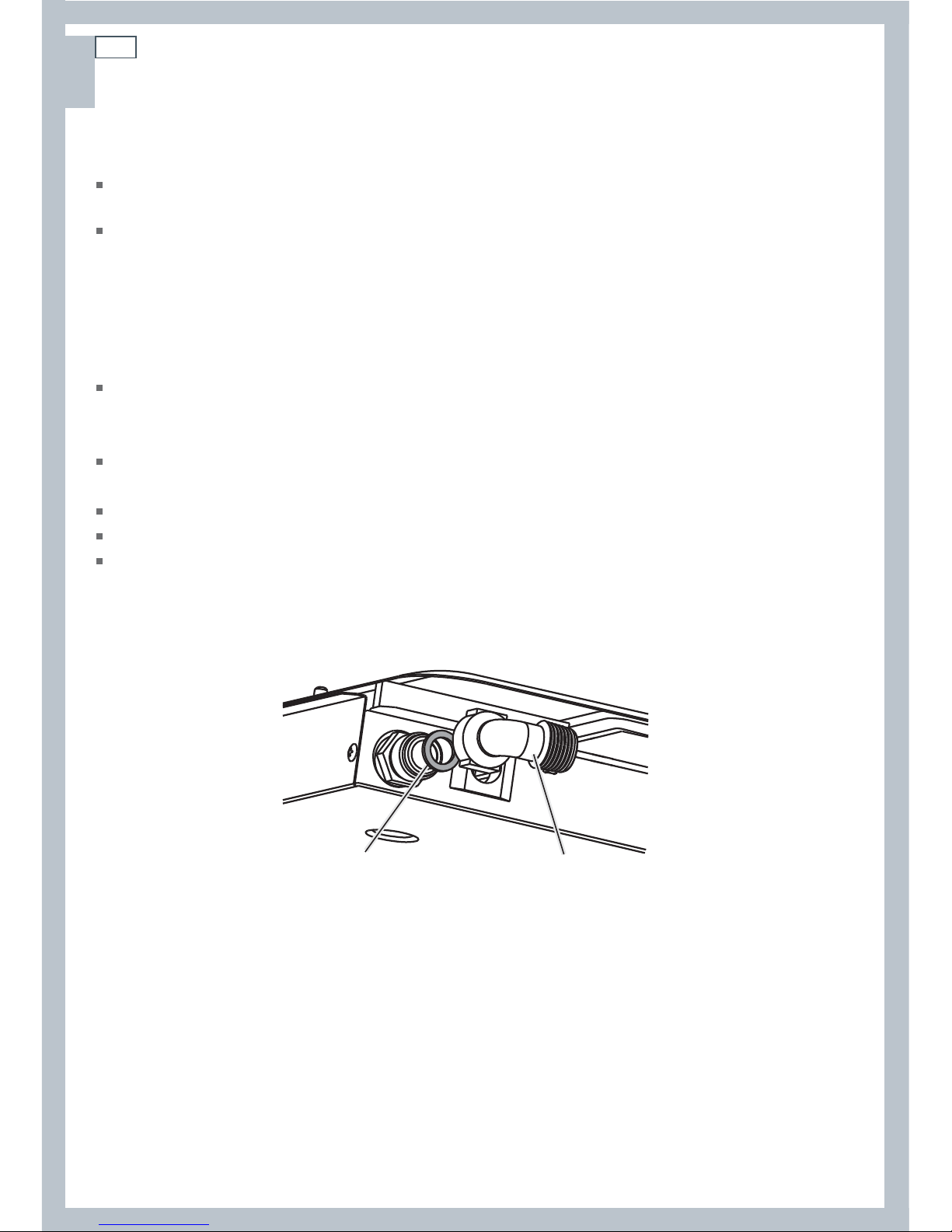
Special requirements for CG604 and CG905DWFC models
Gas connection to these cooktops MUST use the elbow supplied. The regulator will not seal if
installed without it.
Ensure the fibre washer (supplied) is located between the elbow (supplied) and cooktop gas
inlet (Fig.2). Failure to use this washer will cause the connection to leak. Tighten the floating
nut to firm finger tight, plus an additional ¼ turn (90
o
).
Gas connection with a flexible hose
If the gas is connected with a flexible hose, the connector on the wall should be between 800850 mm above the floor and to a distance of at least 250 mm outside the width of the cooktop.
The connector should be accessible with the cooktop installed.
Flexible hose assemblies should be certified. The thread connection shall be Rp ½” (ISO 7-1)
female. See Fig. 2.
The hose assembly must be as short as practicable and comply with relevant requirements.
The hose must not be kinked, subjected to abrasion or permanently deformed.
The hose must not be near or in contact with any hot surfaces (eg base of metal hotplate, flue or
chassis of underbench oven etc).
Fibre washer
Elbow (1/2” BSP external thread)
Fig.2 Gas connection to the cooktop
(CG604 and CG905DWFC models)
Page 13
11
EN
Installation instructions
Leak-testing and flame-testing the cooktop
Important!
The operation of the cooktop, including the ignition system, must be tested before installation is complete.
If, after following the instructions below, satisfactory performance cannot be obtained, contact the local
gas authority or your local Authorised Repairer for advice and assistance.
Checking the connections for leaks
After installation and making all connections, check thoroughly for possible leaks and make sure
all connections are gas-tight.
1
Turn all control dials to O (OFF).
2
Open the valve on the gas supply.
3
Check each connection one at a time by brushing a soap and water solution or a suitable leak
detection fluid over it.
Important!
Do not use any naked flames to check for leaks.
The presence of bubbles indicates a leak. Tighten or replace connections as appropriate, then
leak-test all connections again. For CG604 and CG905DWFC models, ensure the fibre washer
(supplied) is located between the elbow and the cooktop’s gas inlet.
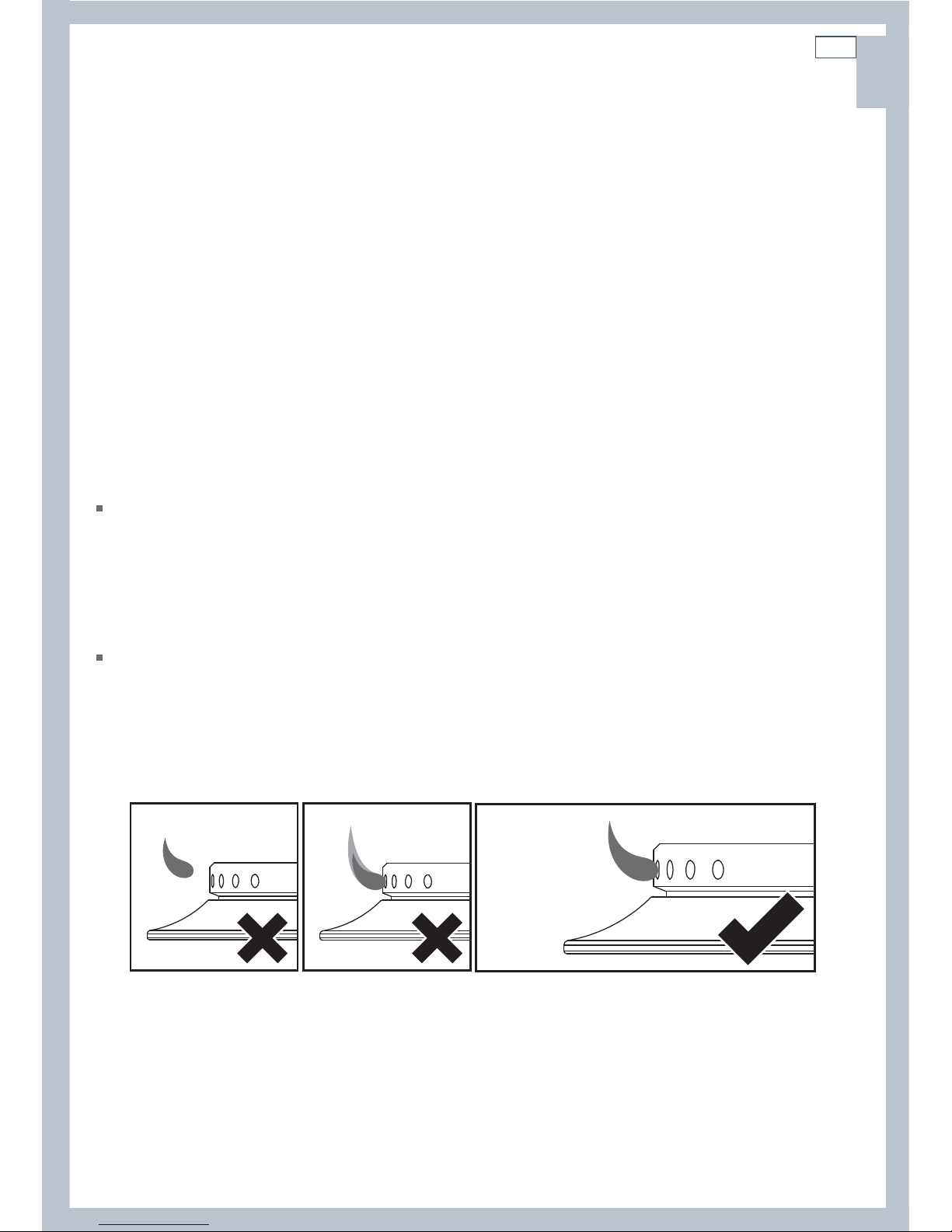
Checking the burner flames
1
Light each burner.
2
Check for a well-defined blue flame without any yellow tipping. See Fig.3.
If any abnormality is evident, check that:
- the burner cap is located properly
- the injector nipple is correctly aligned
- the correct size injectors are installed.
Incorrect: flame
‘lifting off’ the burner
Incorrect:
yellow tipping
Good flame: well-defined blue flame
without yellow tipping
Fig.3 Incorrect and good flame patterns
Page 14
12
EN
Installation instructions
Converting to a different gas type
Important!
Gas conversion may only be carried out by a suitably qualified person.
To convert from one gas type to another, you need to replace the injectors and adjust the
minimum burner setting.
To replace the injectors, you will need a 7 mm box spanner (not supplied).
1
Switch the power supply to the cooktop off at at the wall.
Important!
Disconnect cooktop from the power supply before continuing.
2
Make sure each control dial is turned to O (OFF).
3
Remove all the pan supports and burner heads.
4
Pull off the control dials.
5
Using a 7 mm box spanner, remove the injectors and replace them with the correct ones
(size numbers are stamped on the inside, eg 70=0.70 mm). Hold on to the card housing the
replacement injectors for later use.
6
Check insulation resistance and earth continuity.
7
Switch the power supply to the cooktop back on at the wall.
8
Refit the control dials.
9
Adjust the minimum burner setting. See section ‘Adjusting the minimum burner setting’
following.
10
Check that all burners have a good flame (Fig.3).
11
To indicate the gas type change, peel the adhesive label off the replacement injector card and
stick it into the framed ‘gas type’ area on the appliance data label (on the underside of the
cooktop). A second conversion label should also be affixed to the duplicate appliance data label.
Page 15
13
EN
Installation instructions
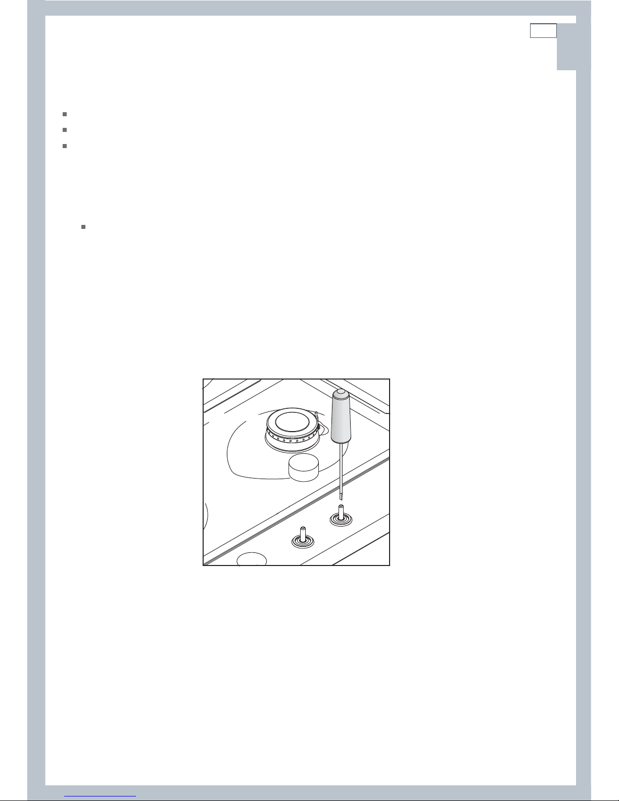
Adjusting the minimum burner setting
This has been adjusted at the factory for Town Gas but may need adjusting for local conditions.
When converting to LPG, the minimum setting MUST be re-adjusted for each burner.
To adjust the minimum setting, you will need a Ø 2.5 x 45 mm screwdriver.
1
Light the burner and set the control dial to its minimum.
2
Remove the dial.
3
Slowly turn the adjustment screw inside the valve shaft until a minimum regular flame is
achieved. Note:
The flame will diminish when the screw is turned clockwise, and increase when turned
anti-clockwise.
4
Refit the dial.
5
Check the minimum burner setting: quickly turn the dial from maximum to minimum. The flame
must not go out. If it does, repeat the steps above.
Repeat the steps above for each burner.
Fig.4 Adjusting the minimum burner setting
Page 16

14
EN
Installation instructions
Gas rate and injector size table
CG604DWFCX & CG905DWFCX Gas Cooktop
This product has been set either for Singapore LPG or Town Gas (this is marked on the
product) but the minimum setting may need adjusting for a particular installation.
The gas rates and injectors are noted in the table below;
BURNER TYPE
AUX SR TR
NOMINAL POWER (W) 1000 1750 3600
REDUCED POWER (W) 350 450 1500
Additional
marking
Additional
marking
Additional
marking
INJECTOR
(1/100mm
or marking)
Natural gas
LPG
Town Gas
20mbar
29mbar
8mbar
72 X 97 Z 140 -
50 - 65 - 95 -
145 1 190 2 320 -
SR SR
AUX
TR
TR
SR SR
TR
AUX
Page 17
15
EN
Final checklist
TO BE COMPLETED BY THE INSTALLER
Have you securely fastened the cooktop to the bench with the supplied brackets?
Have you used the supplied elbow and fibre washer to connect the gas to the inlet on the
cooktop?
Have you leak-tested all connections?
Are the injector sizes correct for the gas type?
Is the shut-off valve on the gas supply accessible to the customer?
Is the power supply isolating switch accessible to the customer?
Is the cooktop power supply cable plugged into an earthed outlet?
Check the entire length of the power supply cable: it should not touch any hot metal parts.
Have you removed all protective film from the stainless steel surfaces?
Have you disposed of all packaging elements?
OPERATION:
Do all burners light individually and in combination?
Do the burners remain lit when turned quickly from maximum to minimum?
Are the flames consistent, free from any yellow tipping and appropriately sized?
Have you demonstrated the basic operation to the customer?
Installer’s name:
Installer’s signature:
Installation company:
Date of installation:
LEAVE THESE INSTRUCTIONS WITH THE CUSTOMER
Installation instructions
Page 18
16
EN
Introduction
About your new cooktop
Thank you for buying a Fisher & Paykel gas cooktop. Once it is installed and ready to use, you
will want to know everything about it to make sure you get excellent results right from the start.
We recommend you read the whole guide before using your new cooktop, for both safety and
cooking success.
For more information, visit our local website listed on the back cover.
Before using your new cooktop
Read this user guide, taking special note of the ‘Safety and warnings’ section.
Ensure the power supply to the cooktop is turned on.
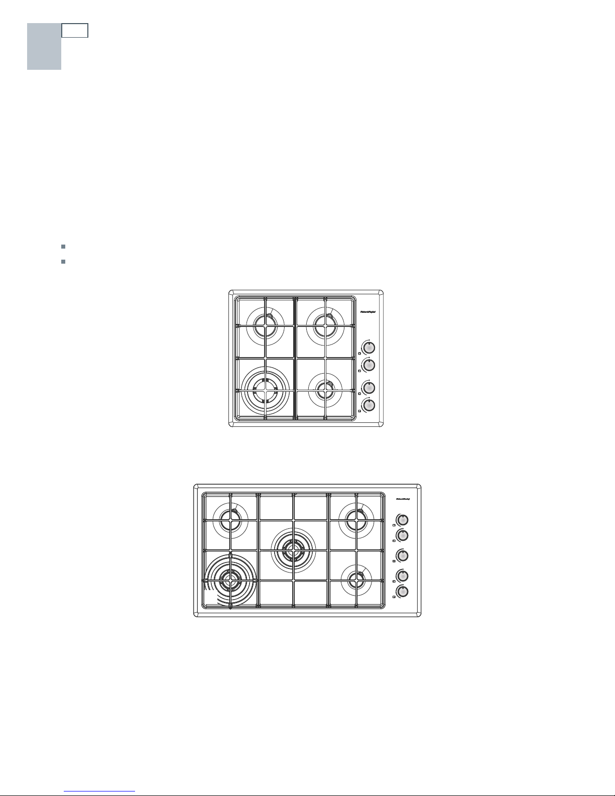
1
Semi-rapid burner
2
Rapid burner
3
Wok burner
4
Auxiliary burner
5
Control dials
Fig.6 Cooktop layout - CG905DWFC
(with flame failure protection)
Fig.5 Cooktop layout - CG604DWFC (with
flame failure protection)
1
11
5
5
4
3
3
1
43
Page 19

17
EN
Control dials
The dials control the flow of gas through the valve.
Using the burners
Models with flame failure protection
1
Press the selected burner’s dial down gently and
turn it anti-clockwise to HIGH.
The ignitors on all the burners will spark.
2
Hold down the dial for about 5 seconds after the burner
has lit. Releasing the dial too soon will extinguish the flame.
3
Adjust the flame anywhere between HIGH and LOW.
Do not adjust between HIGH and O (OFF).
4
After use, always turn the dials to O (OFF).
Using your cooktop
Fig. 8 Pressing down then
turning the control dial
Fig. 7 Control dial for CG604 & CG905DWFC models
NEVER cook or
leave the dial
between HIGH
and O (OFF)
LOW
OFF (closed valve)
HIGH
Burner
indicator
Page 20

18
EN
Using your cooktop
If a burner does not light
Turn the control dial to O (OFF) and wait at least 1 minute before trying again. This
is to allow the gas to disperse. If after trying again the burner still does not light, check that:
the cooktop is plugged in and the power supply is switched on
there is no power failure in your home or neighborhood
the gas is turned on
the gas bottle is not empty (if you use bottled gas)
the ignitors are sparking. If they are not sparking, they may be dirty or wet. Clean them with
a toothbrush and methylated spirits, as shown in Fig. 9 below. See ‘Care and cleaning’ for
instructions on removing and replacing the burner parts.
If the flame is irregular
Check that the burner parts (flame spreader and burner cap) are:
clean and dry
positioned correctly, as shown in Figs. 10 and 11.
For further advice, see sections ‘Care and cleaning’ and ‘Troubleshooting’.
Fig.9 Cleaning the ignitor and probe
Ignitor
Flame failure probe
(models with flame failure protection only)
Ignitor
Flame spreader
Burner cap
Fig.10 Burner parts Fig.11 Correct assembly
of burner parts
Fig.12 Incorrect assembly
of burner parts, resulting in
irregular flames
Page 21

19
EN
Using your cooktop
If there is a power failure
You can still use your cooktop.
Light the burners by holding a match close to the side of the burner and turning the control dial
to HIGH. Wait until the flame is burning evenly before adjusting.
If the flame is accidentally extinguished
The flame failure protection will automatically cut the gas supply to the burner off.
Turn the corresponding dial to O (OFF) and do not try to relight it for at least 1
minute (to allow the gas to disperse).
Page 22

20
EN
Cooking guidelines and cookware
Cooking guidelines
Important!
Never leave the cooktop unattended when in use. Boilover causes smoking and greasy spills that
may ignite.
Take care when deep-frying: oil or fat can overheat very quickly, particularly on a high setting.
Start cooking on a high setting. When food comes to the boil, reduce the setting and maintain a
steady heat to cook your food thoroughly. Doing this will reduce the cooking time.
Using a lid will reduce cooking times through retaining the heat.
Minimise the amount of liquid or fat to reduce cooking times.
Cookware
Use saucepans with thick flat bases. Food in a saucepan with an uneven base will take longer to
cook.
Do not let large saucepans or frying pans overlap the bench, as this can deflect heat onto your
benchtop and damage its surface.
Always make sure saucepans are stable. Using very heavy saucepans may bend the pan supports
or deflect the flame.
Make sure the size of the pan matches the size of the burner. A small pot on a large burner is not
efficient.The following table shows the minimum and maximum saucepan base diameters that
may be used on each burner:
Burner Minimum ∅ Maximum ∅
Semi-rapid
12 cm -
Rapid
18 cm 26 cm
Wok
regular pans 18 cm 26 cm
woks - 45 cm
Auxiliary
12 cm -
Page 23

21
EN
Cooking guidelines and cookware
Using a wok – models with wok burner
Use your wok only on a wok burner.
A wok must always be used with the wok stand supplied. See Fig.13.
Make sure the wok does not push any other pans aside. This could make them unstable, or
deflect heat onto nearby walls or the benchtop.
Important!
Make sure that the wok stand is stable: its notches need to fit tightly on the grating.
Note: to purchase additional wok stands, contact Customer Care.
Fig.13 Using wok stand
Page 24

22
EN
Care and cleaning
What?
How often?
How?
Important!
Stainless
steel base
After every
use
1
Soak any stubborn stains under a hot
soapy cloth.
2
Wipe the soiling off with a cloth using
a mild household detergent or stainless
steel cleaner.
3
Wipe with a clean damp cloth.
4
Wipe the surface dry with a microfibre
cloth.
5
For extra shine, use a suitable stainless
steel polish.
Hard water spots can be removed with
household white vinegar.
Do not use abrasive cleaners,
steel soap pads or sharp
objects on stainless steel.
Always read the label to make
sure that your stainless steel
cleaner does not contain
chlorine compounds as these
are corrosive and may damage
the appearance of your
cooktop.
Always rub the stainless steel in
the direction of the grain.
The graphics are etched onto
the steel by laser and will not
rub off.
Control dials
As needed
1
Wipe with a damp cloth and mild
detergent.
2
Dry thoroughly with a soft cloth.
Do not use stainless steel or oven
cleaner on the dials, as doing so
may damage their coating.
Important!
Before any cleaning or maintenance, always:
turn all burners off
switch the power to the cooktop off at the wall
make sure that the cooktop and its parts are a safe temperature to touch.
General advice
Clean the cooktop regularly—do not let stains become burnt on.
Do not use abrasive cleaners, cloths or pads to clean any part of your cooktop. Some nylon
scourers may also scratch. Check the label.
Make sure that no cleaner residue is left on any cooktop part; when heated, these could stain the
cooktop.
See the following pages for instructions on replacing the pan supports and reassembling the
burners correctly after cleaning.
Do not clean cooktop parts in a self-cleaning oven.
Do not use a steam cleaner.
Page 25

23
EN
Care and cleaning
What?
How often?
How?
Important!
Burner
parts, pan
supports,
wok stand
As needed,
but at least
once a month
1
Remove the parts that you wish to clean.
See the Figs. following for illustrations of
removable burner parts.
2
Soak stubborn stains in a solution of
biological clothes washing detergent.
3
Clean the parts in hot soapy water. Use
a stiff nylon brush or straight-ended
paper clip to clear the notches of a flame
spreader.
4
Rinse in warm water.
5
Dry thoroughly.
6
Replace the parts correctly, following
Figs. 14-18.
These parts are also dishwasher safe.
Make sure you keep the
notches of the flame spreaders
clear. Soiling may clog these
and cause problems.
Before replacing the burner
parts, make sure that they are
completely dry. Wet burner
parts may result in an irregular
flame. Before lighting a burner
you have reassembled, check
that all of its parts have been
positioned correctly. Incorrect
assembly can cause dangerous
irregular flames and ignition
problems.
Ignitor and
probe
At least once
a month
Clean these very carefully using a toothbrush
and methylated spirits (see Fig. 9).
The ignitor ensures trouble-free
sparking and the probe ensures
that the safety valves operate
correctly. Check the ignitor and
probe regularly to make sure
they are clean.
Note: only models with flame
failure protection have probes.
All gas
components
of the
cooktop
Once every
3-4
years
Contact your local Authorised Repairer
to perform a thorough check on all gas
components on the cooktop.
For Authorised Repairer details, see
your Service & warranty book or contact
Customer Care.
All checking and maintenance
must be performed by a
suitably qualified person.
If the gas is connected with a
flexible hose, checking should
include inspecting the entire
length of the flexible hose
assembly for any sign of wear
or damage.
Page 26

24
EN
Care and cleaning
Replacing the pan supports correctly
CG905 models
The wok support goes in the centre, over the wok burner. The other two pan supports are
interchangeable, but need to be rotated to match the rounded corners of the cooktop base.
CG604 models
The pan supports are interchangeable, but they can only be placed as shown and need to be
rotated to match the rounded corners of the cooktop base.
Fig.15 Correct positioning of pan supports (CG604 models)
Fig.14 Correct positioning of pan supports (CG905 models)
Page 27

25
EN
Care and cleaning
Replacing the burner parts correctly
Semi-rapid, rapid, and auxiliary burners
Wok burner with cast iron cap and ring
Fit the flame spreader to the housing as shown by the arrow in Fig.17 following. Make sure the
burner is not able to rotate.
Fig.16 Correct positioning of semi-rapid, rapid,
and auxiliary burner parts
Fig.17 Correct positioning of cast iron wok burner parts
Cap
Ignitor
Flame
spreader
Flame spreader
Cap
Ring
Probe
(some models only)
Probe
(some models only)
Ignitor
Page 28

26
EN
Problem Possible solutions
A burner does not light.
Check that the power to the cooktop is switched on at the
wall and there is no power failure.
Check the gas supply valve is turned on and the supply to
the house is working. You should hear the gas when you
turn a burner on.
If you use bottled gas, check that it is not empty.
The ignitors may be dirty. Clean them with a toothbrush
and methylated spirits, as shown in Fig. 14.
The burner parts may not be located properly. Check the
assembly and make sure the burner cap is sitting flat. See
‘Care and cleaning’.
The flames are yellow or
hard to start.
The burner parts may not be located properly. Check the
assembly and make sure the burner cap is sitting flat. See
‘Care and cleaning’.
If you use bottled gas, this may indicate you are getting
near the end of the bottle.
Check the burner parts are clean and dry.
The gas pressure may not be at the correct level. Check this
with your service person or installer.
Your cooktop may not be set up for the gas you are using.
Check this with your service person or installer.
One of my burners has
an uneven flame.
Check the burner parts are clean and dry.
The burner parts may not be located properly. Check the
assembly and make sure the burner cap is sitting flat. See
‘Care and cleaning’.
The flame goes out at
low settings.
The gas supply pressure may be low. Check this with your
service person or installer.
The low setting may have been adjusted incorrectly. Check
this with your service person or installer.
If you use bottled gas, this may indicate you are getting
near the end of the bottle.
My burners do not turn
down much (when
running on bottled gas
or LPG).
Your cooktop may not have been adjusted correctly.
Check this with your service person or installer.
The flame tips are very
yellow.
Call your service person to service the cooktop.
There is a power failure.
You can still use your cooktop.
Light the burners by holding a match close to the side of
the burner and turning the control dial to HIGH. Wait until
the flame is burning evenly before adjusting.
Troubleshooting
Page 29

27
EN
Warranty and service
Before you call for service or assistance ...
Check the things you can do yourself. Refer to the installation instructions and your user guide
and check that:
1
Your product is correctly installed.
2
You are familiar with its normal operation.
If after checking these points you still need assistance, please refer to the Service & Warranty
book for warranty details and your nearest Authorised Service Centre, or contact us through our
website:
www.fisherpaykel.com
Product details
Fisher & Paykel Ltd
Model Serial No.
Date of Purchase Purchaser
Dealer Suburb
Town Country
Page 30

中文
中文
Page 31

29
目录
安全警告
30
安装说明
34
简介
44
使用燃气灶
45
烹饪原则和厨具
48
保养和清洁
50
故障排除
55
保修和服务
57
重要!
妥善保存这些说明书
本说明书所述的型号并非在所有市场上销售,随时会有变动。如要详细
了解本国销售的型号和规格,请访问封底列出的网站,或者联系当地的
斐雪派克经销商。
中文
中文
Page 32

30
安装
警告!
割伤危险
在处理不锈钢电器时,要注意锋利边沿。
如不小心,可能会造成人身伤害或割伤。
警告!
触电危险
在处理燃气灶的电气部分之前,必须断开供电电源。
必须连接良好接地线。
如果要改动室内布线,必须由资深电工进行改动。
如不遵照此建议,可能会造成触电甚至死亡。
安全警告
中文
中文
Page 33

31
重要安全须知!
安装
在安装或使用燃气灶之前仔细阅读说明书。
请让燃气灶安装人员阅读此信息,因为这可以降低安装成本。
燃气灶只能由授权人士进行安装和维修。
安装不当可能会造成人身伤害或财物损失,制造商对此不承担任何责任,保修或责任求偿自
动失效。
必须根据这些说明、当地燃气安装法规、城市建筑法律、供水法规、电气布线法规和其他任
何相关法规的要求安装燃气灶。
切勿改动燃气灶。
不带熄火保护器的燃气灶不得安装在船舶或房车上。
在安装燃气灶之后,不得把燃气灶当作取暖器。
不得把易燃物或产品放在燃气灶上。
切勿在使用燃气灶时在周围喷气雾剂。
切勿用硅胶或胶水把燃气灶固定在灶台上,否则日后很难维修。斐雪派克不承担此类产品
的除胶成本,对产品在除胶过程中可能发生的修理损坏不承担任何责任。
在安装过程中和安装之后,切勿把包装材料(例如塑料袋、聚苯乙烯泡沫、搭扣和包装带)
放在燃气灶附近,尤其不能放在儿童够得到的地方,否则可能会造成严重人身伤害。
安全警告
中文
中文
Page 34

32
安全警告安全警告
警告!
警告!
灶面烧伤危险
燃气灶在使用过程中会发热。
切勿触摸发热的燃气灶零部件、灶头、三脚架、平底锅锅圈或底板。
在清洁燃气灶之前关闭灶头,等到整个灶台冷却后再清洁。
如不遵照此建议,可能会造成严重人身伤害。
火灾危险
在使用燃气灶时,切勿远离燃气灶。长时间煮沸会产生烟雾,并溢出可燃性
油脂。
切勿用燃气灶取暖。
如不遵照此建议,可能会造成严重人身伤害。
警告!
触电危险
在清洁或维护燃气灶之前,要把燃气灶电源插头从墙壁插座上拔下来。
如不遵照此建议,可能会造成死亡或触电。
警告!
爆炸危险
不带熄火保护器的燃气灶:如果火焰意外熄灭,立刻关闭控制旋钮和燃
气阀,并打开门窗通风。在确信所有泄漏燃气已排出室外之前,切勿尝
试再次点燃灶头。
切勿在燃气灶周围使用或存放汽油等易燃物。切勿在使用燃气灶时在周
围喷气雾剂。
如不遵照此建议,可能会造成死亡或严重人身伤害。
操作
中文
中文
Page 35

33
安全警告
重要安全须知!
操作
在使用燃气灶时,让儿童远离灶台。
切勿让儿童玩弄家用燃气灶。
监护人应该指导儿童或残疾人如何使用燃气灶。监护人应该确保他们能在不危及自身安
全和环境安全的情况下使用燃气灶。
如果电源线破损,必须由授权人士进行更换。确保电源插头在安装燃气灶之后便于插拔。
燃气灶应该连接装有隔离开关的供电线路,隔离开关在必要时把电源隔离开。
切勿在火焰和炖锅之间使用石棉毡或装饰盖,否则可能会严重损坏燃气灶。
切勿把铝箔或塑料碟子放在灶头上。
切勿把大炖锅或平底锅放在灶台上,否则会把热量转移到灶台上损坏灶台。
切勿把大炖锅、平底锅或铁锅放在正在烹饪的其他任何锅旁边。这可能会使大炖锅、
平底锅或铁锅不稳,或者把热量投向灶台损坏表面。
切勿使用蒸汽清洁器清洁燃气灶。
炖锅手柄可能很烫,以至无法触碰。确保炖锅手柄不在其他正在使用的灶头之上。
让儿童够不到手柄。
切勿站在燃气灶上,切勿在燃气灶上堆放重物。
确保在使用燃气灶之后把旋钮开关打到OFF(关)位置。
不得把燃气灶当作取暖器,尤其是在船舶和房车上。
在使用燃气灶时,厨房温度和湿度会升高。确保厨房通风良好。打开自然通风口,
或者安装机械通风设备(抽油烟机)。如果长时间使用燃气灶,可能需要强制通风,
例如打开窗子,或者安装效率更高的通气设备,例如增大机械通风设备的通风口。
在打开燃气灶包装之后,确认燃气灶完好无损。
如果怀疑燃气灶有任何损坏,切勿使用燃气灶,请联系供应商或资深技术员。
切勿把包装材料(例如塑料袋、聚苯乙烯泡沫、搭扣和包装带)放在燃气灶附近,
尤其不能放在儿童够得到的地方,否则可能会造成严重人身伤害。
某些燃气灶的不锈钢零部件和铝合金零部件上贴有保护膜。必须撕掉保护膜,才能使用燃
气灶。
安全警告
中文
中文
Page 36

34
安装说明
A
B
C
D
E
F
G
H
I
J
燃气灶尺寸和开口尺寸(mm)
CG604
CG905
A
燃气灶总宽度
578 914
B
燃气灶总深度
511 533
C
燃气灶台面下的底板高度
50 50
D
底板宽度
554 840
E
底板深度
480 480
F
开口总宽度
560 870
G
开口总深度
490 494
H
开口转角半径
最大10 最大10
I
开口右边到歧管中心线的距离
30 30
J
开口后边到进气管的距离
40 47
中文
中文
Page 37

35
安装说明
距离(mm)
CG604
CG905
A
开口左边到下列各项的最小间隙:
最近的可燃性表面
140 140
B
开口右边到下列各项的最小间隙:
最近的可燃性表面 140 140
C
开口后边到下列各项的最小间隙:
最近的可燃性表面
最近的非可燃性表面
110
20
110
30
D*
在邻近墙壁上使用的非可燃性材料的最小高度
150 150
E
平底锅锅圈到下列各项的最小距离:
抽油烟机
其他悬空排气扇
面朝下的可燃性表面(吊柜)
面朝下的瓷砖表面或耐火面
650
800
650
500
650
800
650
500
F
灶台上表面到下列各项的最小间隙:
最近的可燃性表面
斐雪派克烤箱或最近的非可燃性表面
60
60
60
60
G
确保在距燃气灶右后方900mm范围内装有带接地线的电源插座。
在安装燃气灶时,应该便于把插头插入电源插座。
H
如果用软管连接燃气灶和气源,墙壁上的进气管接头应该距地面800-850mm高,
距燃气灶的距离至少250mm。在安装燃气灶时,应该便于把插头插入电源插座。
* 参看下面的标准要求。
C
E
A
F
B
G
H
D
中文
中文
Page 38

36
安装说明
在开始之前
在开始安装燃气灶之前,确保:
燃气灶在运输途中不破损。如果在打开包装检查后怀疑有破损,请联系经销商。
当地的供气条件(燃气质量和压力)与(燃气灶数据标签和下面的燃气流速和喷嘴尺
寸表标明的)燃气灶调节条件相一致。
必须把燃气灶连接到220-240V 50Hz电源,并通过电源线接地。
在燃气灶电源线所及的地方装有带接地线的电源插座(在距燃气灶右后方900mm内,
参看距离部分的尺寸G)。
电源插座在安装燃气灶之后便于插拔。
电源线不接触任何发热金属零部件。
根据当地布线法规的要求,在永久性布线中安装一个合适的隔离开关实现与供电电源
完全断开。隔离开关必须是经核准的开关类型,所有电极(如果当地布线法规考虑到
此要求变化,为所有有效[相]导体)的触点气隙间隔为3mm。
隔离开关在安装燃气灶之后便于开关。
灶台用耐热材料制成。
开口裸露边沿用油漆或防水聚氨酯密封,防止湿气渗入燃气灶边沿和灶台之间。
中文
中文
Page 39

37
安装说明
把燃气灶固定在灶台上
燃气灶配有固定支架(和螺丝),把燃气灶固定在20-50mm厚的灶台上。如果灶台厚度
超过50mm,可以把底面凹进去至20-50mm。
把燃气灶接到气源上
重要!
燃气灶在出厂前设置为只能使用民用煤气,但如果安装与燃气类型相符的喷嘴,可以使用民用
煤气或液化石油气。参看燃气流速和喷嘴尺寸表了解额定值和相应的喷嘴尺寸,同时参看把燃
气灶连接到不同的燃气接头上一节。
必须由适当的资深人士根据相关标准进行燃气连接。
如果使用民用煤气,把气源接到随燃气灶一并提供的气压调节阀上。 (Bromic; BM-WF-1A) .
确保的供气调节到8毫巴(3.2“WC)
如果使用液化石油气,把气源接到随燃气灶一并提供的测试点转接头上。确保把气压调节到
27.5 mBar (11" W.C.)。参看把燃气灶连接到不同的燃气接头上一节。
确保管接头在安装燃气灶之后便于接触。
为了便于切断气源,确保在靠近燃气灶的地方安装隔离阀。
把相同的燃气灶数据标签贴在燃气灶旁边的表面上,安装燃气灶时很容易看到标签。
参看把燃气灶连接到不同的燃气接头上一节,了解如何连接燃气灶使用不同的燃气。
20mm
50mm
凹进至
50mm
图1 把燃气灶固定在灶台上
中文
中文
Page 40

38
安装说明
CG604型和CG905DWFC型特殊要求
这些燃气灶的燃气接头必须使用随机提供的弯头。如果安装时不使用弯头,调节阀不密封。
确保在(随机提供的)弯头和燃气灶进气管之间垫上(随机提供的)纤维垫圈(图2)。
如果不使用此垫圈,会造成接头漏气。用手指拧紧浮动螺母,再拧紧¼ 圈(90
o
)。
把软管接到燃气接头上
如果用软管连接燃气,墙壁上的进气管接头应该距地面800-850mm高,距燃气灶的距离
至少250mm。在安装燃气灶时,应该便于把插头插入电源插座。
软管应该通过认证。螺纹接头必须是Rp ½" (ISO 7-1)母螺纹。参看图2。
软管必须尽可能短,必须符合相关要求。
软管不得打结,否则容易造成磨损或永久性变形。
软管不得靠近或接触任何发热表面(例如金属发热板底部、烟道或灶台下面的烤箱底板等)。
纤维垫圈
弯头(1/2" BSP外螺纹)
图2 把燃气接到燃气灶上
(CG604型和CG905DWFC型)
中文
中文
Page 41

39
安装说明
燃气灶漏气测试和点火试验
重要!
必须测试燃气灶使用情况,包括点火系统,安装才算完成。如果在执行下列任务之后仍
然无法实现令人满意的性能,请联系当地燃气公司或当地授权修理店寻求建议和协助。
检查接头是否漏气
在安装燃气灶并接好所有接头之后,全面检查接头是否漏气,确保所有接头不漏气。
1
把旋钮开关打到O(关)位置。
2
打开供气管路上的阀门。
3
在每个接头上涂上肥皂水或合适的捡漏液,每次检查一个接头。
重要!
切勿用明火检查是否漏气。
如果有气泡,说明接头漏气。拧紧接头,必要时更换接头,然后再测试所有接头是否
漏气。对于CG604型和CG905DWFC型,确保在弯头和燃气灶进气管之间垫上(随机提
供的)纤维垫圈。
检查灶头火焰
1
打开每个灶头。
2
检查火焰是否呈蓝色,而不带黄色。参看图3。
如果发现异常情况,检查:
— 灶头盖是否盖好
— 喷嘴是否调准
— 安装的喷嘴尺寸是否合适
异常:
火焰远离灶头
异常:
火焰带黄色
正常火焰:
火焰呈蓝色,不带黄色
图3 异常火焰和正常火焰
中文
中文
Page 42

40
安装说明
把燃气灶连接到不同的燃气接头上
重要!
燃气转换只能由资深人士进行。
如要使用另一种燃气,必须更换喷嘴,然后调节灶头最小设置。
更换喷嘴需要一把7mm套筒扳手(不随机提供)。
1
把燃气灶电源插头从墙壁插座上拔下来。
重要!
断开燃气灶电源,然后继续。
2
确保把每个控制旋钮打到O(关)位置。
3
移开所有平底锅锅圈,然后拆卸灶头。
4
拔出控制旋钮。
5
用7mm套筒扳手拆卸喷嘴,然后换上相应尺寸的喷嘴(内侧印有尺寸编号,
例如70=0.70mm)。妥善保存喷嘴包装纸卡供日后使用。
6
检查绝缘电阻和接地导通电阻。
7
接通墙壁上的燃气灶电源开关。
8
重新安装控制旋钮。
9
调节灶头最小设置。参看下面的“调节灶头最小设置”一节。
10
检查所有灶头火焰是否正常(图3)。
11
如要注明燃气变化情况,撕下备用喷嘴纸卡上的不干胶标签,把它贴在(燃气灶底面的)
燃气灶数据标签的“燃气类型”处。应该把第二个转换标签贴在燃气灶旁边的相同燃气
灶数据标签上。
中文
中文
Page 43

41
安装说明
调节灶头最小设置
灶头在出厂前针对民用煤气设置好了,但可能需要根据当地的供气情况进行调节。
在转换使用液化石油气时,必须重新调节每个灶头的最小设置。
调节最小设置需要一把Ø2.5 x 45mm螺丝刀。
1
点燃灶头,然后把控制旋钮打到最小位置。
2
拔出控制旋钮。
3
慢慢旋转阀轴内的调节螺丝,直到最小火焰正常为止。注意:
顺时针旋转调小火焰,反时针旋转调大火焰。
4
重新安装控制旋钮。
5
检查灶头最小设置:把控制旋钮迅速从最大位置打到最小位置。火焰不得熄灭。
如果火焰熄灭,重复执行上述步骤。
对每个灶头重复执行上述步骤。
图4:调节灶头最小设置
中文
中文
Page 44

42
安装说明
燃气流速和喷嘴尺寸表
CG604DWFCX和CG905DWFCX燃气灶
燃气灶设置为使用新加坡的液化石油气或民用煤气(在产品上注明),但可能需要针对特
定的安装情况调节最小设置。
下表说明燃气流速和喷嘴:
灶头类型
AUX SR TR
额定功率(W)
1000 1750 3600
降低功率(W)
350 450 1500
附加标注 附加标注 附加标注
喷嘴
(1/100mm
或标注)
天然气
液化石油气
民用煤气
20兆巴
29兆巴
8兆巴
72 X 97 Z 140 —
50 — 65 — 95 —
145 1 190 2 320 —
SR SR
AUX
TR
TR
SR SR
TR
AUX
中文
中文
Page 45

43
最后检查
下列检查应该由安装人员进行
是否用随机提供的支架把燃气灶牢牢固定在灶台上?
是否用随机提供的弯管和纤维垫圈把燃气接到燃气灶进气口上?
所有接头是否进行过漏气测试?
喷嘴尺寸是否适合所用的燃气?
用户是否便于开关供气管路上的截流阀?
客户是否便于开关电源隔离开关?
燃气灶电源线是否插入带接地线的插座?
检查整个电源线:电源线切勿接触任何发热金属零部件。
是否撕掉不锈钢表面贴的所有保护膜?
是否正确处置所有包装材料?
操作:
所有灶头是单独点火还是同时点火?
把旋钮开关从最大打到最小时,灶头是否仍然在燃烧?
火焰是否均匀?火焰是否带黄色?大小是否合适?
你是否向客户演示过基本操作?
安装人员姓名:
安装人员签名:
安装公司:
安装日期:
把说明书留给客户
安装说明
中文
中文
Page 46

44
简介
关于新燃气灶
感谢你购买斐雪派克燃气灶。在安装好燃气灶之后,要了解如何始终能达到最
佳效果。为了安全和烹饪成功起见,建议你在使用新燃气灶之前通读用户指南。
如要了解详情,请访问封底列出的地区网站。
在使用新燃气灶之前
阅读本用户指南,要特别留意安全警告一节。
确保接通燃气灶电源。
1
中火灶头
2
大火灶头
3
铁锅灶头
4
小火灶头
5
控制旋钮
图6 燃气灶布局 — CG905DWFC
(带熄火保护器)
图5 燃气灶布局 — CG604DWFC
(带熄火保护器)
1
11
5
5
4
3
3
1
43
中文
中文
Page 47

45
控制旋钮
旋钮控制流过阀门的气流。
使用灶头
带熄火保护器的燃气灶
1
轻轻按下所选灶头对应的旋钮,然后反时针旋转到HIGH
(最大)位置。
所有灶头的点火器打火花。
2
在灶头点火之后按住旋钮约5秒钟。如果很快释放旋钮,
火焰会熄灭。
3
在HIGH(最大)和LOW(最小)之间调节火焰。
切勿在HIGH(最大)和O(关)之间调节火焰。
4
在使用完燃气灶之后,始终要把旋钮打到O(关)位置。
使用燃气灶
图8 按下并旋转控制旋钮
图7 CG604型和CG905DWFC型控制旋钮
切勿烹饪,切勿
让旋钮留在HIGH
(最大)和O
(关)之间
LOW(最小)
OFF(关,阀门关闭)
HIGH(最大)
灶头指
示器
中文
中文
Page 48

46
使用燃气灶
如果灶头不点火
把控制旋钮打到O(关),等一分钟后再试一次。这样让灶头的燃气散开掉。
如果再次尝试仍然不点火,检查:
燃气灶电源插头是否插好,电源是否接通。
家里和邻居是否停电。
燃气是否打开。
燃气罐是否空了(如果使用罐装燃气)。
点火器是否打火花。如果点火器不打火花,可能是点火器脏了或受潮。用牙刷蘸甲基化酒
精清洁点火器,如下面的图9所示。参看保养和清洁一节了解如何拆卸和更换灶头零部件。
如果火焰异常
检查灶头零部件(分火盘和灶头盖)是否:
清洁干燥。
在如图10和图11所示的正确位置。
参看保养和清洁一节和故障排除一节进一步了解建议。
图9 清洁点火器和传感器
点火器
熄火传感器
(带熄火保护器的燃气灶)
点火器
分火盘
灶头盖
图10 灶头零部件 图11 灶头零部件安装
正确
图.12 灶头零部件安装错
误造成火焰异常
中文
中文
Page 49

47
使用燃气灶
如果停电
仍然可以使用燃气灶。
用火柴从灶头侧面点燃灶头,然后按下控制旋钮并把它打到HIGH(最大)位置。
等到火焰燃烧均匀再调节火力大小。
如果火焰偶尔熄灭
熄火保护器自动切断灶头气源。
把相应的旋钮打到O(关),切勿在一分钟之内再次尝试点火(让灶头的燃气散开掉)。
中文
中文
Page 50

48
烹饪原则和厨具
烹饪原则
重要!
在使用燃气灶时,切勿远离燃气灶。长时间煮沸会产生烟雾,并溢出可燃性油脂。
油炸食物时要小心:油脂可能迅速过热,尤其是在使用大火时。
用大火开始烹饪。在煮食物时调小火力,用恒温把食物热透。这样可以缩短烹饪时间。
盖上锅盖不让热量散发,可以缩短烹饪时间。
最大限度地减少汁液,可以缩短烹饪时间。
烹饪用具
使用平底厚炖锅。如果用锅底不平的炖锅烹饪食物,烹饪时间较长。
切勿把大炖锅或平底锅放在灶台上,否则会把热量转移到灶台上损坏灶台。
始终要确保放稳炖锅。如果使用很重的炖锅,可能会压弯平底锅锅圈或使火焰偏向一边。
确保炖锅大小与灶头大小相匹配。在大灶头上使用小锅效率不高。下表说明可在每个灶头
上使用的炖锅的最小锅底直径和最大锅底直径:
灶头 最小直径 最大直径
中火
12cm —
大火
18cm 26cm
铁锅
规则锅
18cm 26cm
铁锅
— 45cm
小火
12cm —
中文
中文
Page 51

49
烹饪原则和厨具
使用铁锅 — 带铁锅灶头的燃气灶
只能在铁锅灶头上使用铁锅。
在使用铁锅时,必须使用随机提供的铁锅锅圈。参看图13。
确保铁锅不把其他平底锅推到一边,否则会使平底锅不稳,或者把热量集中在附近的墙壁或
灶台上。
重要!
确保铁锅锅圈很稳:凹槽必须紧紧卡在格栅上。
注意:如要额外购买铁锅锅圈,请联系客户服务部。
图13 使用铁锅锅圈
中文
中文
Page 52

50
保养和清洁
什么?
频率?
如何?
重要!
不锈钢底板
在每次使用
之后
1
用热肥皂水浸泡顽固污迹。
2
用抹布蘸中性家用洗涤剂或不锈钢清洁
剂擦拭污迹。
3
用干净的湿抹布擦拭。
4
用超细纤维清洁布擦干表面。
5
如要提高光亮度,要使用合适的不锈钢
抛光剂。
可以用食用白醋除去硬水留下的斑点。
切勿用有研磨作用的清洁剂、
钢丝棉擦子或锋利物体擦拭
不锈钢。
始终要阅读标签,确保不锈钢
清洁剂不含氯化物,因为氯化
物有腐蚀性,可能会损坏燃气
灶表面。
始终按拉丝方向擦拭不锈钢。
图标是用激光刻在不锈钢
上的,擦不掉。
控制旋钮
必要时
1
用湿抹布蘸中性清洁剂擦拭。
2
用软抹布擦干
。
切勿用不锈钢清洁剂或烤箱清洁剂
清洁旋钮,否则可能会损坏涂层。
重要!
在清洁或维护之前始终要:
关闭所有灶头。
把燃气灶电源插头从墙壁插座上拔下来。
确保燃气灶及其零部件在安全温度范围内。
一般性建议
定期清洁燃气灶 — 切勿让食物残渣烧焦。
切勿用有研磨作用的清洁剂、抹布或擦子清洁燃气灶的任何零部件。某些尼龙清
洁用品也可能会刮花燃气灶。检查标签。
确保燃气灶的任何零部件不残留清洁剂;当燃气灶工作时,残留物会变成污渍。
参看后面几页了解在清洁燃气灶之后,如何正确放回平底锅锅圈并组装灶头。
切勿用自动清洁烤箱清洁燃气灶零部件。
切勿使用蒸汽清洁器。
中文
中文
Page 53

51
保养和清洁
什么?
频率?
如何?
重要!
灶头零部件、
平底锅锅圈
和铁锅锅圈
必要时,
但一个月至
少一次
1
取出要清洁的零部件。
参看插图,遵循可拆卸灶头零部件插图
说明。
2
把有顽固污迹的零部件浸入有机布洗涤剂
溶液中。
3
用热肥皂水清洁零部件。用硬尼龙刷或拉
直的回形针清洁分火盘凹槽。
4
用温水冲洗干净。
5
用干抹布擦干。
6
根据图14-18正确安装零部件。
这些零部件也可以用洗碗机清洗。
确保分火盘凹槽清洁。污迹
可能会阻塞这些凹槽并引发
问题。
在更换灶头零部件之前,确保
这些零部件是干的。灶头零部
件潮湿可能会造成火焰异常。
在重新组装零部件之后,检查
所有零部件的位置是否正确,
然后再点火。组装错误可能
会造成危险的火焰异常和点
火问题。
点火器和
传感器
一个月至少
一次
用牙刷蘸甲基化酒精清洁点火器和传感器
(参看图9)。
点火器确保打火花无故障,
传感器确保安全阀正常工作。
定期检查点火器和传感器,
确保它们清洁。
注意:只有不带熄火保护器
的燃气灶有传感器。
燃气灶所有燃
气零部件
每3-4年一次
联系当地的授权修理店全面检查燃气灶的
所有燃气零部件。
参看维修和保修手册或联系客户服务部了
解当地授权修理店的联系方法。
所有检查和维护必须由资深人
员进行。
如果用软管连接气源,还应该
检查整个软管是否有磨损或损
坏迹象。
中文
中文
Page 54

52
保养和清洁
正确放回平底锅锅圈
CG905型
铁锅锅圈位于铁锅灶头正上方。其他两个平底锅锅圈可以互换,
但必须旋转平底锅锅圈使其与燃气灶底板上的圆角相匹配。
CG604型
平底锅锅圈可以互换,但只能如图所示放置,必须
旋转平底锅锅圈使其与燃气灶底板上的圆角相匹配。
图15 正确的平底锅锅圈位置(CG604型)
图14 正确的平底锅锅圈位置(CG905型)
中文
中文
Page 55

53
保养和清洁
正确放回灶头零部件
中火灶头、大火灶头和小火灶头
带铸铁盖和环的铁锅灶头
如图17箭头所示把分火盘装入卡槽。确保灶头不会转动。
图16 正确的中火灶头、
大火灶头和小火灶头的位置
图17 正确的铸铁锅灶头位置
灶头
盖
点火器
分火盘
分火盘
灶头盖
环
传感器
(仅部分型号)
传感器
(仅部分型号)
点火器
中文
中文
Page 56

54
问题 可能的原因
灶头不点火。
检查墙壁上的燃气灶电源是否接通,是否停电。
检查是否打开燃气阀,是否有燃气通到家里。
在打开灶头时,应该听到燃气发出的嘶嘶声。
如果使用罐装燃气,检查燃气罐是否空了。
点火器可能脏了。用牙刷蘸甲基化酒精清洁
点火器,如图14所示。
可能灶头零部件安装位置错误。检查安装情况,
确保灶头盖放平。参看保养和清洁一节。
火焰呈黄色或难打火。
可能灶头零部件安装位置错误。检查安装情况,
确保灶头盖放平。参看保养和清洁一节。
如果使用罐装燃气,可能是燃气罐里的燃气不多了。
检查灶头零部件是否清洁干燥。
可能燃气压力不合适。请维修人员或安装人员调节
燃气灶。
燃气灶设置可能与要使用的燃气不一致。请维修人
员或安装人员调节燃气灶。
其中一个灶头的火焰
不稳定。
检查灶头零部件是否清洁干燥。
可能灶头零部件安装位置错误。检查安装情况,
确保灶头盖放平。参看保养和清洁一节。
旋钮打到最小时熄火。
可能燃气压力太小。请维修人员或安装人员调节燃气灶。
可能最小设置调节错误。请维修人员或安装人员调节燃
气灶。
如果使用罐装燃气,可能是燃气罐里的燃气不多了。
(在使用罐装燃气或液
化石油气时)灶头调低
量很小。
可能是没有正确调节燃气灶。
请维修人员或安装人员调节燃气灶。
焰尾很黄。
致电维修人员前来维修燃气灶。
停电。
仍然可以使用燃气灶。
用火柴从灶头侧面点燃灶头,然后按下控制旋钮并把它
打到HIGH(最大)位置。等到火焰燃烧均匀再调节火力
大小。
故障排除
中文
中文
Page 57

55
保修和维修
在致电寻求服务或协助之前……
自己先检查燃气灶。阅读安装说明书和用户指南,并检查:
1
产品安装是否正确。
2
你是否熟悉正常操作。
如果在进行上述检查之后仍然需要协助,请阅读维修和保修手册了解保修信息和最近的授权服
务中心,或者访问网站联系我们:
www.fisherpaykel.com
产品数据
Fisher & Paykel Ltd
型号 序列号
购买日期 购买人
经销商 县市
乡镇 国家
中文
中文
Page 58

Page 59

Page 60

HK SG
08.2013F&P PN - 590582 A F&P意大利 PN - 1104278-ß1
www. sherpaykel.com
Copyright © Fisher & Paykel 2013.
The product specifications in this booklet apply to the specific products
and models described at the date of issue. Under our policy of continuous
product improvement, these specifications may change at any time. You
should therefore check with your Dealer to ensure this booklet correctly
describes the product currently available.
Copyright © Fisher & Paykel 2013.版权所有。
本手册所述的产品规格适用于截至发行日所销售和描述的特定产
品型号。本公司禀承不断改进产品之政策,上述规格可能随时会有
变动。因此,请向当地经销商咨询,确保本手册所述的产品是当前
销售的产品。
 Loading...