

Fisher & Paykel CG301D, CG451, CG903D, CG752D Installation Instructions Manual

Gas-on-glass cooktop
CG301D, CG451, CG752D & CG903D
models
HK SG
INSTALLATION INSTRUCTIONS
590631C 02.16
www.fisherpaykel.com

1
2
IMPORTANT!
SAVE THESE INSTRUCTIONS
The models shown in this installation guide may not be available in all markets and are subject to change at any time. For current details about model and specification availability in your country, please go to our
website www.fisherpaykel.com or contact your local Fisher & Paykel dealer.
IMPORTANT SAFETY INSTRUCTIONS
Particular attention shall be given to
the relevant requirements regarding
ventilation.
Read these instructions carefully before
installing this product.
Please make this information available
to the person installing the appliance
as it could reduce your installation
costs.
This appliance is to be installed and
serviced only by an authorised person.
Installation must comply with your local
building and local gas authority codes
and electricity regulations.
Incorrect installation, for which the
manufacturer accepts no responsibility,
may cause personal injury or damage
and could invalidate any warranty or
liability claims.
Appliances are factory set for LPG or
Town Gas (Hong Kong) or Town Gas
(Singapore). If in doubt, refer to the
local gas network operator of gas
supplier to confirm gas type at the
installation site.
1 SAFETY AND WARNINGS
WARNING!
Electrical shock hazard
Disconnect the appliance from
the mains electricity supply
before carrying out any work or
maintenance on it.
Connection to a good earth wiring
system is essential and mandatory.
Alterations to the domestic wiring
system must only be made by a
qualified electrician.
Failure to follow this advice may
result in electrical shock or death.
WARNING!
Cut Hazard
Take care - panel edges are sharp.
Failure to use caution could result
in injury or cuts.
!
!

3
IMPORTANT SAFETY INSTRUCTIONS
Appliances are factory set for Natural
gas but are convertible to LPG. If in
doubt, refer to the local gas network
operator or gas supplier to confirm gas
type at installation site.
Do not modify this appliance.
Do not use or store flammable
materials on or near this appliance.
Do not spray aerosols in the vicinity of
this appliance while it is in operation.
Packing elements (eg plastic bags,
polystyrene foam, staples, packing
straps etc) and tools should not be left
around during and after installation,
especially if they are within easy reach
of children, as these may cause serious
injuries.
You must remove the transit screws
before installing the cooktop. See step
8 of installation instructions.
Before you install the appliance, please
make sure that
the local distribution conditions (nature
of gas and pressure) and the adjustment
of the appliance are compatible. For
adjustment conditions for this appliance
see ‘Gas rate summary’.
a suitable disconnection switch is
incorporated in the permanent wiring,
mounted and positioned to comply with
the local wiring rules and regulations.
A means of disconnection with at least
a 3 mm air gap contact separation in
all poles must be incorporated into the
fixed wiring in accordance with the
wiring rules, unless the local wiring rules
allow for alternative means.
the appliance is connected to a 220V
- 240V 50Hz (10 A) power supply only
and earthed via the power supply cable.
there is a power outlet within reach of
the power supply cable (900 mm from
the centre rear of the product). This
must be accessible after installation.
The power supply cable should not
touch any metal parts.
1 SAFETY AND WARNINGS

4
if the power supply cable is damaged,
it is replaced only by the special cable:
Part no. 534906 TRMNL BLOCK-FLEX
ASSY HITEMP GOG UK, obtainable
from authorised Fisher & Paykel Service
Agents. Please see your ‘Service and
Warranty’ booklet for contact details.
the supply connection point (gas shutoff valve) is accessible after installation.
the benchtop is made of a heat resistant
material.
the installation complies with all the
current requirements of National and
Local Authority Gas, Electric and other
relevant Codes and Regulations.
When you install the appliance
As servicing requires removing of the
cooktop from the benchtop we do not
recommend flush mounting. To the
fullest extent permissible by law, the
owner carries all risk for flush mounting
of the cooktop. The owner must ensure
the cooktop has been cut out from the
benchtop before servicing can be carried
out. Fisher & Paykel will not be liable
for any costs associated with removing
or replacing a flush-mounted and/or
sealed-in product, nor for repairing any
damage that may be incurred by doing
this. Fisher & Paykel does not exclude
any statutory liability it may have and
which by law cannot be excluded,
because of the giving of this notice.
If installed with an approved flexible
hose, the hose should not come
in contact with the bottom of the
appliance or any sharp edges. Flexible
hose assemblies should comply with
local regulations.
Seal exposed bare edges of the cutout
with an oil-based paint or moistureproof polyurethane to prevent possible
moisture creeping between the cooktop
trim and the benchtop.
Take extreme care not to chip, crack,
or break the top glass surfaces during
installation. A heavy metal tool or part
accidentally dropped on the glass could
damage it.
If, after following the instructions
given, correct performance cannot be
achieved, please contact your nearest
Fisher & Paykel Authorised Service
Centre, Customer Care, or contact us
through our website listed on the cover
of this document.
1 SAFETY AND WARNINGS
5
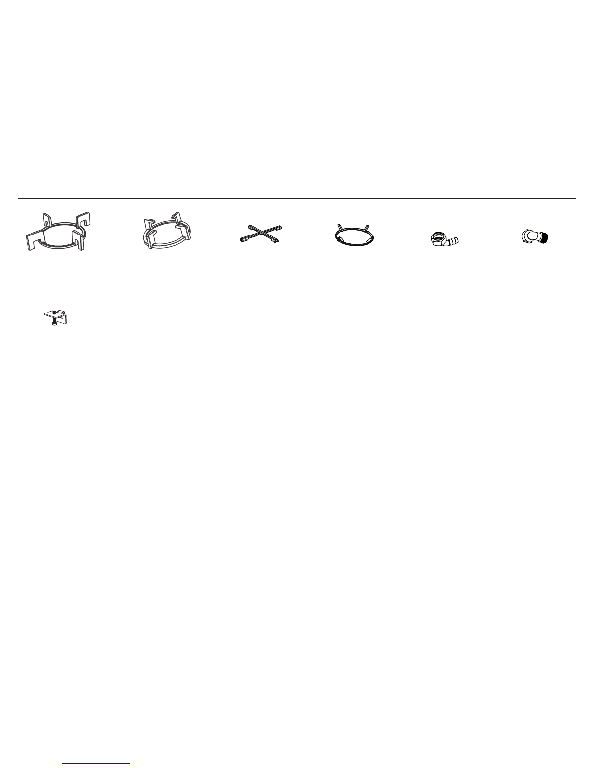
2 PARTS SUPPLIED
Small pan support (1)
(some models only)
Dual Wok Pan support
(1 per Dual Wok)
Wok stand
(1 per Dual Wok)
Gas Elbow (1)
Clamping
brackets (4)
and screws
Installing multiple products
Note: We recommend installing multiple products in separate cutouts, with a minimum 5mm space between the glass edges of the adjacent products.
If installing multiple products adjacent to each other within the same cutout, a separate joining strip kit is required for installation.
The kit is available from the nearest Fisher & Paykel Authorised Service Centre or our website listed on the cover of this document.
If installing different products adjacent to each other (eg a wok burner next to an induction cooktop), the minimum clearance measurements for the different
products may vary. Always use the greater distance.
Semi-rapid Pan
support (1)
(CG903D only)
Elbow 1/2“ BSP
external thread (1)
6
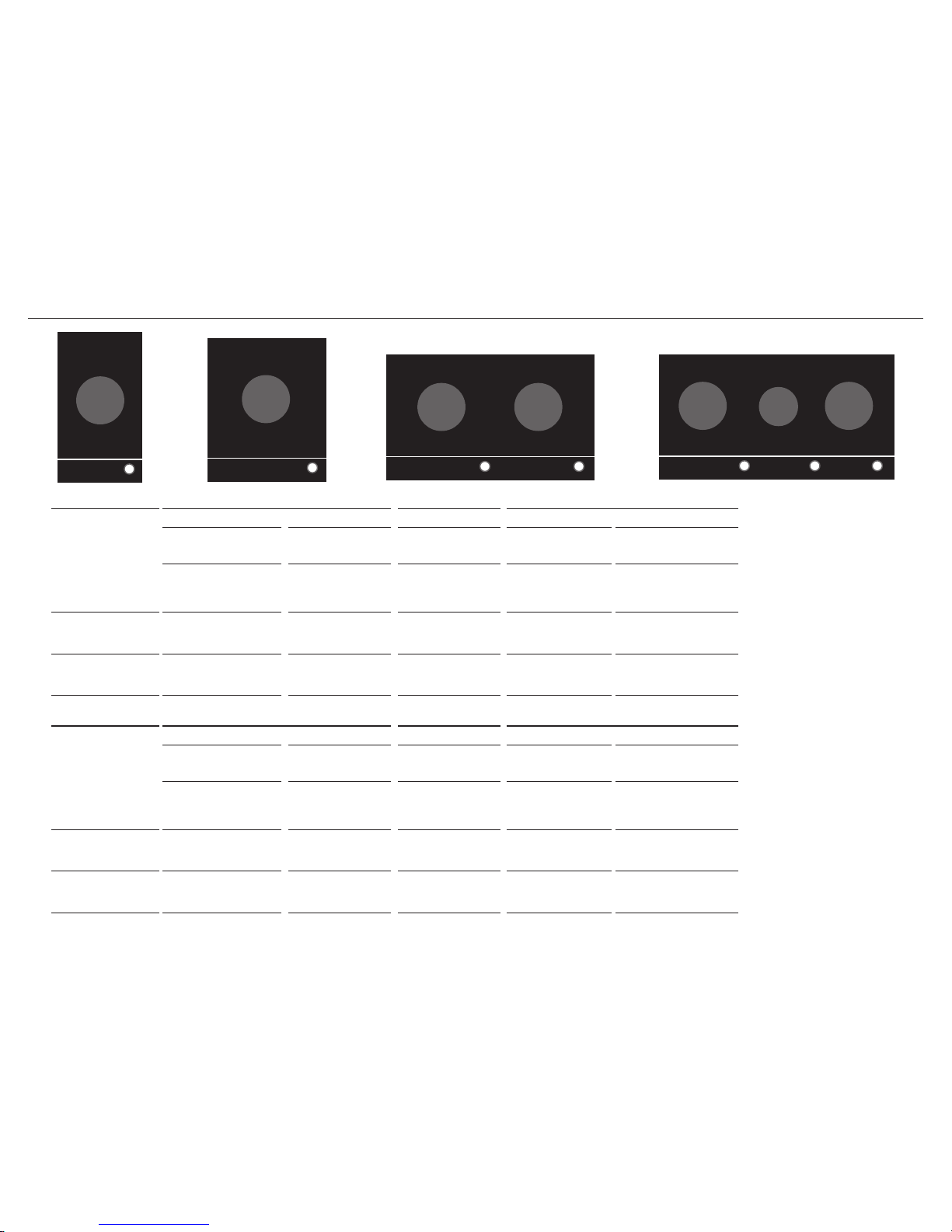
3 GAS RATE SUMMARY
CG301D
CG451D
CG903D
CG752D
SEMI-RAPID
DUAL WOK
DUAL WOK
DUAL WOK
DUAL WOK
DUAL WOK
DUAL WOK
All appliances are factory set for either Natural Gas or LPG.
Check the ‘Gas type’ sticker on the base of the appliance.
HONG KONG
SINGAPORE
GAS TYPE
CG301D CG451D CG752D CG903D
DUAL WOK DUAL WOK DUAL WOK SEMI-RAPID DUAL WOK
Jet size
(mm)
Nominal
rating
(kW)
Jet size
(mm)
Nominal
rating
(kW)
Jet size
(mm)
Nominal
rating
(kW)
Jet size
(mm)
Nominal
rating
(kW)
Jet size
(mm)
Nominal
rating (kW)
TG (G110)
(1.5 kPa/15 mbar)*
2.60
2.60
1.50
X.XX 2.50
2.50
1.30
5.80 2.30
2.30
1.10
5.50 1.55 1.60 2.30
2.30
1.10
5.50
LPG (G30)
(2.9 kPa/29 mbar)*
0.80
0.80
0.50
X.XX 0.80
0.80
0.50
4.86 0.73
0.73
0.50
4.86 0.76 2.36 0.73
0.73
0.50
4.86
GAS TYPE
CG301D CG451D CG752D CG903D
DUAL WOK DUAL WOK DUAL WOK SEMI-RAPID DUAL WOK
Jet size
(mm)
Nominal
rating
(kW)
Jet size
(mm)
Nominal
rating
(kW)
Jet size
(mm)
Nominal
rating
(kW)
Jet size
(mm)
Nominal
rating
(kW)
Jet size
(mm)
Nominal
rating (kW)
TG (G110)
(0.8 kPa/8 mbar)*
3.50
3.50
1.50
5.50 2.50
2.50
1.30
4.00 2.50
2.50
1.30
4.68 2.07 2.20 2.50
2.50
1.30
4.68
LPG (G30)
(2.9 kPa/29 mbar)*
0.80
0.80
0.50
5.50 0.80
0.80
0.50
5.10 0.73
0.73
0.50
5.00 0.76 2.28 0.73
0.73
0.50
5.00
*Nominal pressure with one dual wok burner on High.
7
A
K
D
B
E
C
G
F
J
H
I
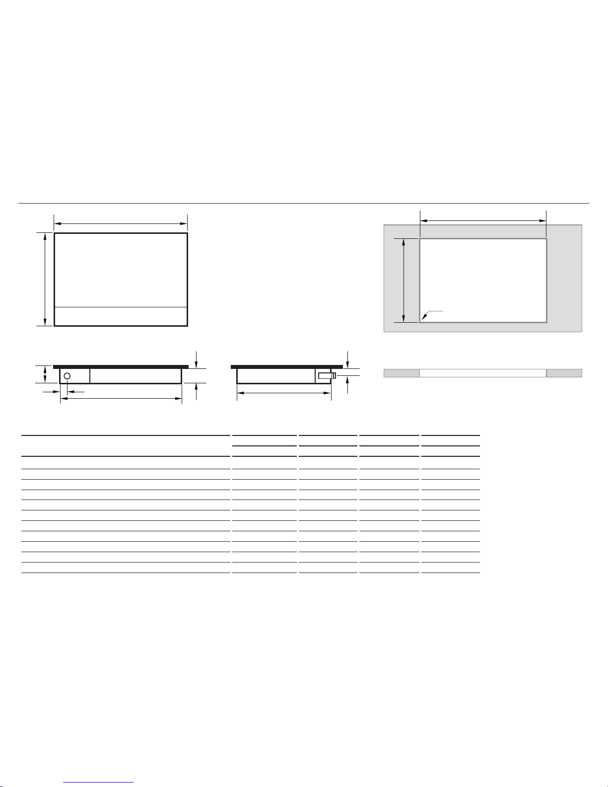
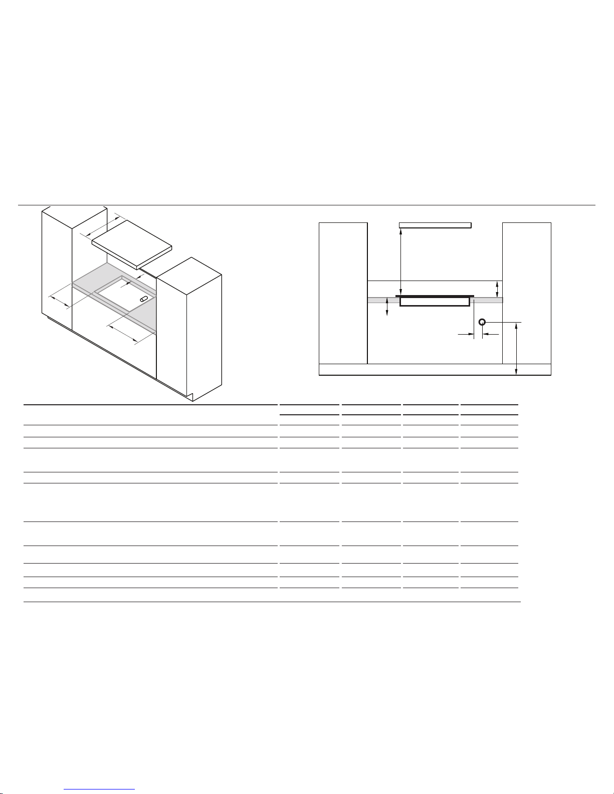
4 PRODUCT & CABINETRY DIMENSIONS
Note: Gas inlet connection is located in the
rear right corner.
FRONT
TOP
TOP
SIDEREAR
PRODUCT AND CABINETRY DIMENSIONS
CG301D CG451D CG752D CG903D
mm mm mm mm
A
Overall height of product (excluding burners, dials and pan supports)
64 64 64 64
B
Overall width of product
300 450 750 900
C
Overall depth of product
530 530 450 450
D
Height of chassis (below top of bench)
59 59 59 59
E
Width of chassis
256 406 706 856
F
Depth of chassis
486 486 410 410
G
Overall width of cutout
260 415 715 865
H
Overall depth of cutout
490 490 410 410
I
Corner radius of cutout
max. 10 max. 10 max. 10 max. 10
J
Distance from top of bench to centre of gas inlet on product
30 30 30 30
K
Distance from edge of chassis to gas inlet on product
21 21 21 21
8
FRONT
ISO
CLEARANCE DIMENSIONS
CG301D CG451D CG752D CG903D
mm mm mm mm
A
Minimum clearance from left edge of cutout to nearest combustible surface 120 60 115 115
B
Minimum clearance from right edge of cutout to nearest combustible surface 120 60 115 115
C
Minimum clearance from rear edge of cutout to:
Nearest combustible surface
Nearest non-combustible surface
85
45
85
45
125
45
125
45
D
Minimum height of non-combustible material when used on adjacent walls 150 150 150 150
E
Minimum clearance from cooktop surface to:
Rangehood
Any other overhead exhaust fan
Downward facing combustible surface
Downwards-facing tiled or fire resistant surface
650
800
650
500
650
800
650
500
650
800
650
500
650
800
650
500
F
Minimum clearance below top of benchtop to:
Combustible surface
Fisher & paykel oven or nearest non-combustible surface
70
65
70
65
70
65
70
65
G
Minimum distance from right edge of cooktop to gas connection point on wall
(if using a flexible hose)
250 250 250 250
H
Distance from floor to gas connection point on wall (if using a flexible hose)
min. 800 -
max. 850
min. 800 -
max. 850
min. 800 -
max. 850
min. 800 -
max. 850
I
Maximum overall depth of overhead cabinetry 600 600 600 600
Note: Ensure there is an earthed power outlet within 900 mm of the centre rear of the product. The gas connector on the wall should be 800-850 mm (H) above the floor and to a distance of at least 250 mm (G) outside the width of
the product, on the right-hand side. It should be accessible with the product installed.
5 CLEARANCE DIMENSIONS
E
H
D
F
G
A
I
B
C
E
H
D
F
G
9
A
K
D
B
E
C
G
F
J
H
I
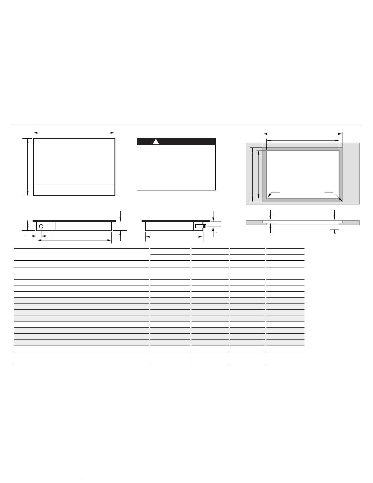
6 FLUSH MOUNTING INSTALLATION (OPTIONAL)
TOP
TOP
FRONT
REAR
SIDE
G
G
K
L
HH
I J
Note: Gas inlet connection is located in the
rear right corner.
PRODUCT AND CABINETRY DIMENSIONS
CG301D CG451D CG752D CG903D
mm mm mm mm
A
Overall height of product (excluding burners, dials and pan supports)
64 64 64 64
B
Overall width of product
300 450 750 900
C
Overall depth of product
530 530 450 450
D
Height of chassis (below top of bench)
59 59 59 59
E
Width of chassis
256 406 706 856
F
Depth of chassis
486 486 410 410
G
Overall width of routered recess
305 455 755 905
G
I
Width of cutout
260 415 715 865
H
Overall depth of routered recess
535 535 455 455
H
I
Depth of cutout
490 490 410 41 0
I
Corner radius of cutout
max. 10 max. 10 max. 10 max. 10
J
Corner radius of routered recess
max. 2 max. 2 max. 2 max. 2
K
Height of routered recess
5 5 5 5
L
Distance from top of bench to centre of gas inlet on product
35 35 35 35
M
Distance from edge of chassis to gas inlet on product
21 21 21 21
N
Minimum clearance below top of benchtop to:
rear top of oven* installed below cooktop or cabinetry
thermal protection barrier
75
70
75
70
75
70
75
70
WARNING!
We do not recommend flush mounting and
sealing as servicing requires the cooktop to
be removed from the benchtop. The owner
carries all risk for flush mounting the cooktop.
The owner must ensure the cooktop has been
cut out from the benchtop before servicing
can be carried out. Fisher & Paykel will not be
liable for any costs associated with removing
or replacing a flush-mounted and/or sealed-in
product, nor for repairing any damage that
may be incurred by doing this.
!
N
M
L
 Loading...