

Fisher & Paykel CG365D, CG365D Series Installation Instructions Manual

US CA
590486B 08.13
CG365D models
Gas cooktop
INSTALLATION INSTRUCTIONS
SAFETY AND WARNINGS
1
IMPORTANT SAFETY INSTRUCTIONS!
This appliance shall be installed in accordance with the installation requirements of the local
gas authority or the appropriate installation code or in the absence of local codes with the latest
National Fuel Gas Code NFPA 54/ANSI Z223.1 or CAN/CSA B149.1,2 (Canada). Local building and
electrical codes must be adhered to.
Electrical installation must be in accordance with the National Electrical Code, ANSI/NFPA70 - latest
edition or CSA C22.1 (Canada) and/or local codes.
Installation in manufactured (mobile) home: installation must conform with the Manufactured Home
Construction and Safety Standard, Title 24 CFR, Part 3280 [formerly the Federal Standard for Mobile
Home Construction and Safety, Title 24, HUD (Part 280)] or, when such standard is not applicable, the
Standard for Manufactured Home Installations, ANSI/NFPA 225, or with local codes where applicable.
Installation in Recreational Park Trailers: installation must conform with state or other codes or, in
the absence of such codes, with the Standard for Recreational Park Trailers, ANSI A119.5.
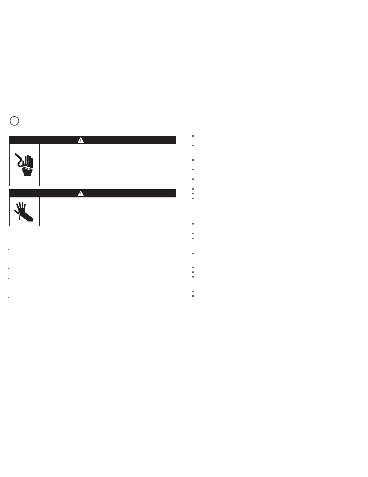
WARNING!
Cut hazard
Take care - panel edges are sharp.
Failure to use caution could result in injury or cuts.
WARNING!
Electrical shock hazard
Disconnect product from the mains power supply before servicing. This
appliance is equipped with a three-prong grounding plug for your
protection against shock hazard and should be plugged directly into a
properly grounded power outlet. Do not under any circumstances cut or
remove the grounding prong from this plug.
Failure to follow this advice may result in electrical shock or death.
Do not remove permanently affixed labels, warnings, or plates from the product. This may void the
warrant y.
Flexible appliance connectors shall meet the requirements of ANSI Z21.24 and State Boards. They
shall not exceed 35 ½ inches (900 mm) in length. In order to avoid hazard, these appliances must be
installed according to these instructions.
This appliance must be installed by an authorized person (Warning: this appliance must be installed
by a licensed plumber or gas fitter when within the Commonwealth of Massachusetts).
Please make this information available to the person installing the appliance as it could reduce your
installation costs.
Please leave these instructions with the appliance. Inform the customer to retain for future reference
and for the local inspectors’ use.
Failure to install the appliance correctly could invalidate any warranty or liability claims.
Leak testing of the appliance shall be conducted according to the manufacturer’s instructions.
Only genuine replacement parts may be used for servicing the appliance. These are available from
your nearest Fisher & Paykel Service Center.
Before you install the appliance, please make sure that
the local distribution conditions (nature of gas and pressure) and the adjustment of the appliance
are compatible. For adjustment conditions for this appliance, see ‘Gas rate summary’ under step 3.
a suitable isolating switch is incorporated in the fixed wiring in an acceptable position.
the appliance is connected to a power outlet that is electrically grounded in accordance with local
codes or in the absence of local codes, with the National Electric Code ANSI/NFPA 70 or CSA C22.2
(Canada).
there is a power outlet (110-120V 60Hz) within reach of the appliance cable (35 1/2” (900 mm) from
the center rear of the appliance). This must be accessible after installation. The mains power supply
cable should not touch any metal parts.
the countertop is square and level and no structural members interfere with space requirements
the countertop is made of heat-resistant material.
you take note of the following recommended non-combustible materials: ¼” (6 mm) flame retardant
millboard covered with not less than No. 28 MSG sheet steel, 1/32” (0.4 mm) stainless steel,
1/32” (0.6 mm) aluminum or 1/32” (0.5 mm) copper.
the gas shut-off valve is accessible after installation.
if the power supply cable is damaged, it is replaced only by the special cable: Part no. 531954 – Flex
Terminal Block Assy US, obtainable from authorized Fisher & Paykel Service Agents.
3
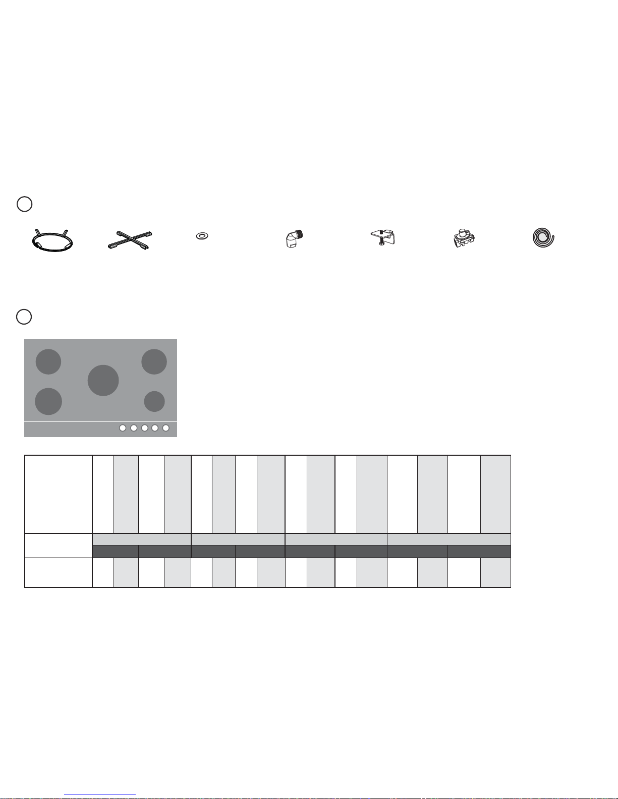
PARTS SUPPLIED
2
Small pan support (1)
Wok stand (1)
Fibre washers (1) Elbow 3/8 “ NPT
external thread (1)
Clamping
brackets (4)
and screws (4)
Regulator (1)
High Altitude Installations
For installations above 3000’ conversion kits are required:
3,000-6,000’ 534695 KIT HI ALT NG
534697 KIT HI ALT LP
6000’+ 534696 KIT HI ALT NG
534698 KIT HI ALT LP
Contact your authorized dealer, customer care or refer to
the website listed at the back of this document.
3
GAS RATE SUMMARY
CG365D
SEMI-RAPID SEMI-RAPID
RAPID
DUAL WOK
AUX
US CA
Injector orifice (mm)
Nominal rating (BTU/hr)
Injector orifice (mm)
Nominal rating (BTU/hr)
Injector orifice (mm)
Nominal rating (BTU/hr)
Injector orifice (mm)
Nominal rating (BTU/hr)
Injector orifice (mm)
Nominal rating (BTU/hr)
Injector orifice (mm)
Nominal rating (BTU/hr)
Injector orifice (mm)
Nominal rating (BTU/hr)
Injector orifice (mm)
Nominal rating (BTU/hr)
NG 4” HO (0.15 psi)*
LP 11” HO (0.39 psi)*
AUX SEMI-RAPID RAPID DUAL WOK
NG LP NG LP NG LP NG LP
CG365D
0.9 3500 0.55 3500 1.40 8500 0.75 6700 1.65 11,500 0.98 11,500
1.50
1.50
0.70
19,000
0.83
0.83
0.50
19,000
Foam tape (1)

4
4
PRODUCT & CABINETRY DIMENSIONS
Product and cabinetry dimensions inches (mm)
CG365D
A
overall height of product (excluding burners, dials and pan supports)
2 ½ ” (64)
B
overall width of product
35 ½ ” (900)
C
overall depth of product
20 ⁄” (530)
D
height of chassis (below top of counter)
2 ⁄” (59)
E
width of chassis
33 ⁄” (856)
F
depth of chassis
19 ⁄” (486)
G
overall width of cutout
34 ⁄” (865)
H
overall depth of cutout
19 ⁄” (490)
I
corner radius of cutout
max. ⁄” (10)
J
distance from top of counter to center of gas inlet on product
1 ¼ ” (32)
K
distance from edge of chassis to gas inlet on product
⁄” (21)
A
K
D
B
E
C
G
F
J
H
I
Note: Gas inlet connection is
located in the rear right corner.
TOP
TOP
REAR
FRONT
SIDE

5
5
CLEARANCE DIMENSIONS
Clearance dimensions (mm)
CG365D
A
minimum clearance from left edge of product to nearest vertical surface 5 ⁄” (130)
B
minimum clearance from right edge of product to nearest vertical surface
4 ½ ” (115)
C
minimum clearance from rear edge of product to:
nearest combustible surface
nearest non-combustible surface*
6 ⁄” (160)
less than 1 ¾ ” (45)
D
minimum clearance from front edge of counter to front edge of product
1 ¼ ” (32)
E
minimum clearance from cooking surface to combustible surface centered above the cooking surface
36 ” (915)
F
maximum overall depth of overhead cabinetry 13 ” (330)
G
minimum distance between overhead cabinets installed to either side of product 36 ” (915)
H
minimum vertical distance between counter and cabinet extending above the counter 18 ” (457)
I
minimum clearance below top of countertop to:
nearest combustible surface
F&P oven or nearest non-combustible surface
2 ¾ ” (70)
2 ⁄” (65)
J
maximum distance from the center of the product to the nearest grounded power outlet.
The power supply cable must not touch any hot metal surfaces.
35 ½ ” (900)
* Recommended non-combustible materials are: 1/4” (6 mm) ame retardant millboard covered with not less than No. 28 MSG sheet steel, 0.015” (0.4 mm) stainless steel,
0.024” (0.6 mm) aluminum or 0.020” (0.5 mm) copper.
FRONT
ISO
E
G
H
J
I
A
F
B
C
D
6
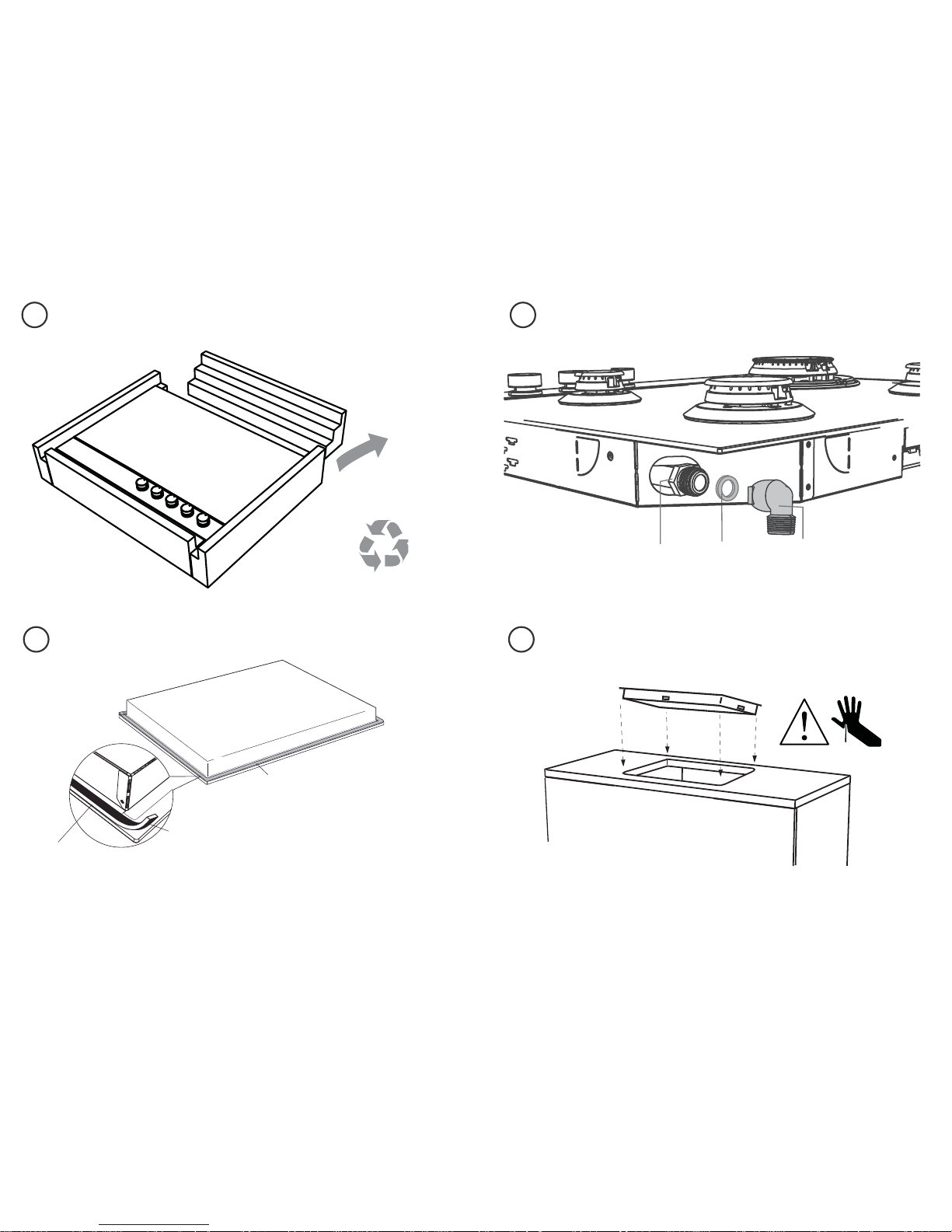
Elbow (3/8 “ NPT external thread)
6
98
7
DISCARD PACKAGING
LOWER GENTLY INTO THE CUTOUTAPPLY ADHESIVE FOAM TAPE AROUND EDGE
FIT THE ELBOW AND WASHER
Recycle responsibly
Model may vary from illustrations shown
Floating nut
Fibre washer
Foam Tape
Adhesive side
Ensure edge of tape
lines up with outer
edge of cooktop
1
Turn the cooktop upside down and
place it on a soft surface.
2
Spread the seal around the edges, with
the adhesive side facing down to form a
continuous seal around the cooktop.
3
Using a sharp cutter or trimmer knife,
trim the excess sealing material around
the edge of the cooktop. Take care not
to damage the countertop.
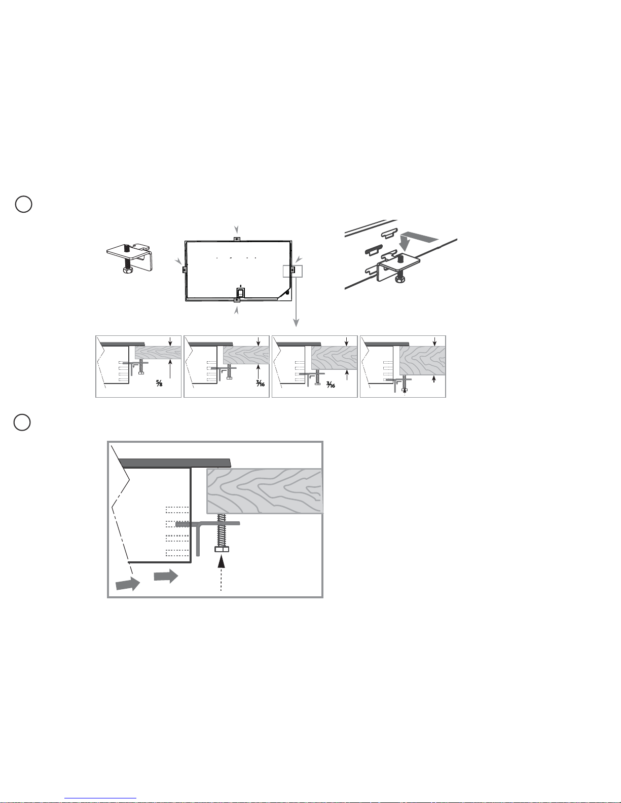
7
11
SECURE TO COUNTERTOP
x 4
Repeat on all the other sides
10
FIT CLAMPING BRACKETS BASED ON THE CounterTOP THICKNESS
”- ¾” ¾”- 1 ”
(16-20mm) (20-30mm)
1
”- 1½”
(30-40mm)
1
½” +
(40mm+)
x 4
view from below
view from below
 Loading...