

Fisher Paykel CG365CWACX1 Owners Manual

Installation instructions
and User guide
Gas cooktops
CG365D & CG365C models
Instructions d’installation
et Guide d’utilisation
Table de cuisson au gaz
Modèles CG365D et CG365C
US CA
WARNING!
If the information in this manual is not
followed exactly, a fire or explosion may
result causing property damage, personal
injury or death.
Do not store or use gasoline or other
flammable vapors and liquids in the vicinity
of this or any other appliance.
NEVER use this appliance as a space heater
to heat or warm the room. Doing so may
result in carbon monoxide poisoning and
overheating of the appliance.
WHAT TO DO IF YOU SMELL GAS
Do not try to light any appliance.
Do not touch any electrical switch.
Do not use any phone in your building.
Immediately call your gas supplier from a
neighbor’s phone. Follow the gas supplier’s
instructions.
If you cannot reach your gas supplier, call the
fire department.
Installation and service must be performed by
a qualified installer, service agency or the gas
supplier.

Contents
1
US
CA
EN
Safety and warnings
Installation instructions
Introduction
Using your cooktop
Cookware
Care and cleaning
Frequently asked questions
Troubleshooting
Warranty and service
2
8
18
19
21
23
25
26
27
Important!
SAVE THESE INSTRUCTIONS
The models shown in this document may not be available in all markets and are
subject to change at any time. For current details about model and specification
availability in your country, please visit our local website listed on the back cover
or contact your local Fisher & Paykel dealer.
US
CA
EN
2
Safety and warnings
Installation
WARNING!
Electrical Shock Hazard
Disconnect product from the mains power supply before servicing.
This appliance is equipped with a three-prong grounding plug for your
protection against shock hazard and should be plugged directly into a
properly grounded power outlet. Do not under any circumstances cut or
remove the grounding prong from this plug.
Failure to follow this advice may result in electrical shock or death.
WARNING!
Cut Hazard
Take care - panel edges are sharp.
Use polystyrene end caps when carrying the product.
Failure to use caution could result in injury or cuts.
Important safety instructions!
This appliance shall be installed in accordance with the installation requirements of the local
gas authority or the appropriate installation code or in the absence of local codes with the latest
National Fuel Gas Code ANSI Z223.1 or CAN/CSA B149.1,2 (Canada). Local building and electrical
codes must be adhered to.
Electrical installation must be in accordance with the National Electrical Code, ANSI/NFPA70 latest edition or CSA C22.1 (Canada) and/or local codes.
Installation in manufactured (mobile) home: installation must conform with the Manufactured
Home Construction and Safety Standard, Title 24 CFR, Part 3280 [formerly the Federal Standard
for Mobile Home Construction and Safety, Title 24, HUD (Part 280)] or, when such standard is
not applicable, the Standard for Manufactured Home Installations, ANSI/NCSBCS A225.1, or with
local codes where applicable.
Installation in Recreational Park Trailers: installation must conform with state or other codes or,
in the absence of such codes, with the Standard for Recreational Park Trailers, ANSI A119.5.
Do not remove permanently affixed labels, warnings, or plates from the product. This may void
the warranty.
Flexible appliance connectors shall meet the requirements of ANSI Z21.24 and State Boards. They
shall not exceed 36 inches in length.
In order to avoid hazard, these appliances must be installed according to these instructions.

Safety and warnings
This appliance must be installed by an authorized person (Warning: this appliance must be
installed by a licensed plumber or gas fitter when within the Commonwealth of Massachusetts).
Please make this information available to the person installing the appliance as it could reduce
your installation costs.
Please leave these instructions with the appliance. Inform the customer to retain for future
reference and for the local inspectors’ use.
Failure to install the appliance correctly could invalidate any warranty or liability claims.
Only genuine replacement parts may be used for servicing the appliance. These are available
from your nearest Fisher & Paykel Service Center.
This product should not be sealed into the countertop with silicone or glue. This will make any
future servicing difficult. Fisher & Paykel will not be liable for costs associated with releasing
such products, nor for damage incurred as a result.
This product is supplied with an additional label containing the model and serial numbers. It
may be affixed to the underside of the product, the inside of a cupboard or to this manual.
3
US
CA
EN
US
CA
EN
4
Safety and warnings
Operation and maintenance
Your safety is important to us. Please read this information before using your appliance.
WARNING!
Explosion Hazard
Do not use water on grease fires. A violent steam explosion may result.
Smother fire or flame or use dry chemical or foam type extinguisher.
Do not use the appliance to heat unopened food containers, such as cans.
This will cause the container to burst and could result in injury.
Do not store flammable materials such as gasoline near the appliance.
Do not spray aerosols in the vicinity of this appliance while it is in operation.
Failure to follow this advice may result in death or injury.
Poisoning Hazard
Clean the appliance with caution. If a wet sponge or cloth is used to wipe
spills on a hot cooking area, be careful to avoid steam burn. Some cleaners
can produce noxious fumes if applied to a hot surface.
Never use this appliance as a space heater to heat or warm the room.
Doing so may result in carbon monoxide poisoning and overheating of the
appliance.
Failure to follow this advice may result in poisoning or death.
WARNING!
Safety and warnings
WARNING!
Electrical Shock Hazard
Before doing any user maintenance, locate the wall power outlet and
disconnect the appliance from the power supply and turn off the gas
supply at the shut-off valve.
This appliance is equipped with a three-prong grounding plug for your
protection against shock hazard and should be plugged directly into a
properly grounded power outlet. Do not under any circumstances cut or
remove the grounding prong from this plug.
Failure to follow this advice may result in electrical shock.
Hot Surface Hazard
Do not touch burners or areas near burners. Burners may be hot even
though they are dark in color. Burners and areas near burners may become
hot enough to cause burns. To avoid risk of burns and/or fire, keep loose
clothing, potholders or any other flammable materials well clear of the
burner flame. Do not touch or let clothing, potholders or other flammable
materials contact burners or areas near burners until they have had sufficient
time to cool. Among these areas are the burners and grates.
Always use a dry potholder when removing cookware from the appliance.
Do not use wet or damp potholders as these can cause steam burns. Do not
use towels or similar cloths for removing cookware.
Do not leave children alone or unattended near the appliance. Never allow
children to stand, sit or play near, on or with the appliance.
Be careful when reaching for items stored in cabinets over the appliance.
Flammable materials could be ignited if brought in contact with flame or hot
surfaces and may cause severe burns.
Failure to follow this advice could result in burns and scalds.
WARNING!
5
US
CA
EN

US
CA
EN
6
Safety and warnings
Important safety instructions!
Have your appliance installed and properly grounded by a qualified installer in accordance with
the installation instructions.
Ensure that a manual gas shut-off valve is installed in a location accessible after installation.
Be sure to have the installer show you how to turn off the gas and electrical supply.
Use this appliance only for its intended purpose as described in this user guide.
Wear proper apparel. Loose fitting or hanging garments should never be worn while using the
appliance.
Turn the pot handles to the side or the back of the appliance away from the reach of children.
Handles should not be positioned over adjacent burners.
Always check that you have turned the burners off when you have finished cooking.
Never leave the appliance unattended when in use. Boilover causes smoking and greasy
spillovers that may ignite.
Before using the appliance, ensure that all burners have been assembled correctly.
Do not operate a burner without all burner parts in place.
Always keep flammable wall coverings, curtains or drapes a safe distance from your appliance.
For safety reasons, the burner flame size should be adjusted so it does not extend beyond the
edge of the cookware.
Use cookware of the appropriate size and construction for the type of cooking. This appliance
is equipped with burners of different sizes. Cookware must be matched to the size of the burner.
Select utensils with flat bottoms large enough to cover the burner flames. The use of undersize
utensils will expose a portion of the burner flames to direct contact and may result in ignition of
clothing. Proper relationship of utensil to burner will also improve efficiency.
Do not stand on this gas appliance.
For safety reasons, do not store items of interest to children above or at the back of the appliance
- children climbing on the appliance to reach items could be seriously injured.
When deep-frying in fat, be sure the pan is large enough not to cause an overflow from bubbling
of the fat. Do not deep-fry foods with a high moisture content or food covered with frost.
Do not let cooking grease or other flammable materials accumulate near the appliance.
Do not repair or replace any part of the appliance unless specifically recommended in this user
guide. All other servicing should be referred to a qualified technician.
Glazed cooking utensils - only certain types of glass, glass/ceramic earthenware, or other glazed
utensils are suitable for cooktop service without breaking due to sudden change in temperature.
Do not use a steam cleaner to clean your cooktop.

Safety and warnings
Important safety instructions!
If/When the appliance is converted for use with Natural Gas or LP/Propane Gas, make sure that
you save the injectors removed from the appliance for future use. To convert to a different gas
type, contact your service agent/gas fitter.
Do not obstruct the flow of combustion and ventilation air to the appliance.
The Governor of California is required to publish a list of substances known to the state of
California to cause cancer or reproductive harm and requires businesses to warn customers of
potential exposures to such substances.
WARNING!: Gas appliances contain or produce substances which can cause death or serious
illness and which are known to the State of California to cause cancer, birth defects or other
reproductive harm. To reduce the risk from substances in fuel or from fuel combustion, make
sure this appliance is installed, operated, and maintained according to the manufacturer’s
instructions.
7
US
CA
EN

US
CA
EN
8
Installation instructions
Cabinet preparation
Make sure that the countertop is flat and level and that no structural members interfere with
space requirements.
Make sure the countertop is made of a heat resistant material.
We recommend that the exposed bare wood edges of the cutout be sealed with an oil based
paint or moisture-proof polyurethane to prevent possible damage from moisture creeping
between the cooktop trim and the countertop.
Electrical
Make sure that there is a power supply receptacle (110-120V 60Hz) within reach of the cooktop
power supply cable (30” from the middle of the product). The power supply cable must not
touch any hot metal parts.
Make sure the cooktop is connected to a power supply socket that is electrically grounded
in accordance with local codes or in the absence of local codes, with the National Electric
Code ANSI/NFPA 70 or CSA C22.2 (Canada). The power supply socket must be accessible after
installation.
The power supply must be properly polarized. Reverse polarity will result in continuous sparking
of the electrodes, even after flame ignition. If the power supply is not properly polarized, it is the
responsibility of the customer to have the polarity corrected.
If there is any doubt as to whether the wall receptacle is properly grounded or polarized, have it
checked by a qualified electrician prior to installing the cooktop.
This appliance is equipped with a three-prong grounding plug for your protection against shock
hazard and should be plugged directly into a properly grounded receptacle. Do not cut or
remove the grounding prong from this plug.

Installation instructions
Parts checklist
Gas cooktop base unit
Literature pack (includes LP kit)
Elbow & blue washer (taped to power supply cable)
Regulator (in polystyrene)
Burner heads and caps (check polystyrene carefully before discarding)
3 x burner grates (1 x center, 2 x outer)
Accessories pack (GC365D only)
Tools needed
Phillips No. 2 screwdriver
Plumbing fittings as required
Woodworking tools as required
Shut-off valve
Oil based paint (for sealing cutout)
For GC365C LP conversion
Ø ⁄ “ x 1¾ ” (Ø2.5 x 45 mm) flat screwdriver
⁄” (7 mm) box spanner
9
US
CA
EN
For GC365D LP conversion
Ø ⁄ “ x 1¾ ” (Ø2.5 x 45 mm) flat screwdriver
Phillips No. 1 screwdriver
⁄” (7 mm) box spanner
⁄” (10 mm) ring spanner
US
CA
EN
10
Installation instructions
B
C
F
E
D
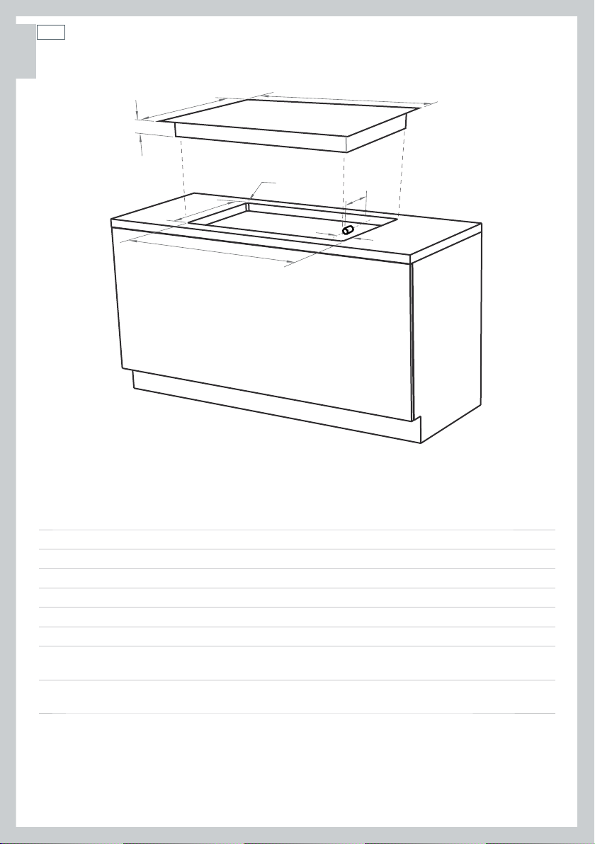
Cooktop and cutout dimensions (inches (mm))
A
H
G
CG365D
CG365C
overall width of cooktop
A
overall depth of cooktop
B
height of chassis below top of counter
C
overall width of cutout
D
overall depth of cutout
E
corner radius of cutout
F
distance from right edge of cutout to
G
manifold center line
distance from rear edge of cutout to
H
gas inlet on cooktop
36 ” (914) 36 ” (914)
21 ½ ” (546) 21 ½ ” (546)
3 ” (76) 2 ⁄” (65)
34 ¼ ” (870) 34 ¼ ” (870)
19 ¼ ” (494) 19 ¼ ” (494)
R ⁄” (10) R ⁄” (10)
1” (25) 1” (25)
¾ ” (20) ¾ ” (20)
Installation instructions
G
F
11
US
CA
EN
H
C
E
D
A
I
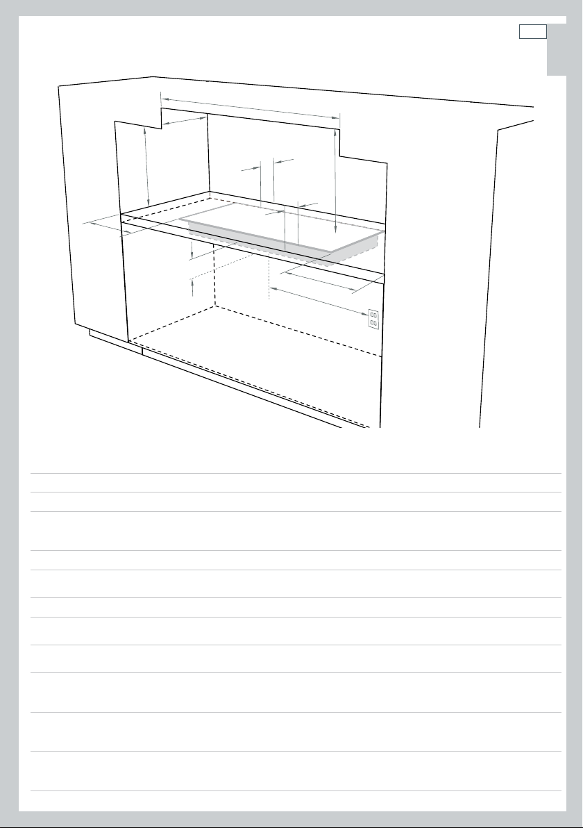
Clearance and cabinetry dimensions (inches (mm))
minimum clearance from left edge of product to nearest vertical surface 1 ½ ” (38) 1 ½ ” (38)
A
minimum clearance from right edge of product to nearest vertical surface
B
minimum clearance from rear edge of product to:
nearest combustible surface
C
nearest non-combustible surface*
minimum clearance from front edge of counter to front edge of product
D
minimum clearance from cooking surface to combustible surface centered
E
above the cooking surface 30 ” (762) 30 ” (762)
maximum overall depth of overhead cabinetry
F
minimum distance between overhead cabinets installed to either side of
G
product
minimum vertical distance between counter and cabinet extending above
H
the counter
minimum clearance below top of countertop to:
nearest combustible surface
I
F&P oven or nearest non-combustible surface
maximum distance from the center of the product to the nearest
grounded power outlet. The power supply cable must not touch any hot
J
metal surfaces.
* Recommended non-combustible materials are: ¼ ” (6 mm) flame retardant millboard covered with not less
than No. 28 MSG sheet steel, 0.015” (0.4 mm) stainless steel, 0.024” (0.6 mm) aluminum or 0.020” (0.5 mm)
copper.
B
J
CG365D
1 ” (25) 1 ” (25)
1 ¼ ” (32)
less than1 ¼ ” (32)
1 ¼ ” (32) 1 ¼ ” (32)
13 ” (330) 13 ” (330)
36 ” (915) 36 ” (915)
18 ” (457) 18 ” (457)
3 ⁄” (84)
3 ⁄” (84)
30 ” (762) 30 ” (762)
less than1 ¼ ” (32)
CG365C
1 ¼ ” (32)
3 ⁄” (84)
3 ⁄” (84)
US
CA
EN
12
Installation instructions
Gas supply connection
This appliance is factory set for use with Natural Gas at 4” of water column pressure. It can
also be used on LP Gas at 11” of water column pressure after conversion (see ‘Converting to a
different gas type’).
A manual shut-off valve must be installed in an accessible location in the gas line external to the
appliance for the purpose of turning on or shutting off gas to the appliance. (In Massachusetts
such shutoff devices should be approved by the Board of State Examiners of Plumbers & Gas
Fitters).
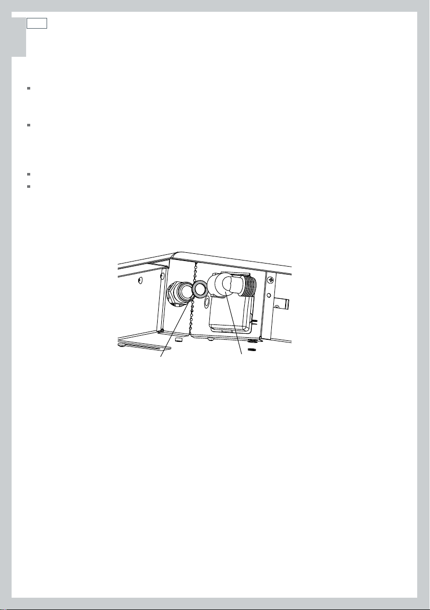
Gas connection to the product must use the elbow supplied with a
Ensure the blue washer (supplied) is located between the elbow and the product inlet.
Failure to use this will cause a gas leak.
1
/2” NPT external thread.
Blue washer
Elbow
Installation instructions
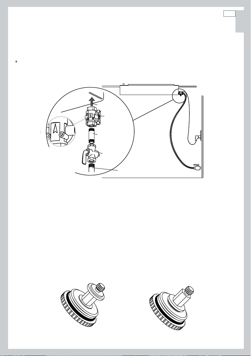
Converting to a different gas type
Gas regulator
For use with a gas pressure regulator as shown below. The regulator supplied can be set for
either LP Gas or Natural Gas.
Cooktop
To Cooktop
Regulator
Solid or Flexible
Connector
13
US
CA
EN
Pressure
Regulator
shows
Direction of
Gas Flow
Converting the regulator between NG & LP
1
Unscrew the cap from the regulator.
2
Check the orientation of the plastic conversion plug, and if necessary, unscrew, turn over and
screw back in (wide section away from cap for LP and against cap for NG - see diagram below for
appropriate orientation).
3
Replace regulator cap.
4
Test gas pressure (test point provision on side of regulator). When converting the regulator for
different settings, the function of the regulator must be checked at a pressure at least 1” WC
(0.036 psi) above the specified manifold pressure.
LP NG
Shut-Off
Valve
Pipe Stub from
House supply
14
US
CA
EN
Installation instructions
Converting to a different gas type
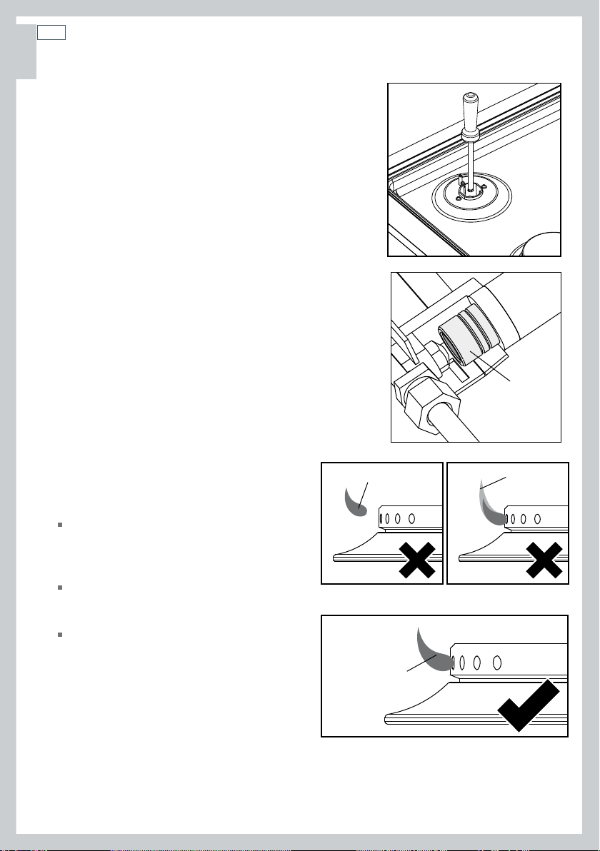
Changing the injectors
The cooktop is set to NG. A conversion kit to LP is supplied
with the cooktop.
To change the injectors, you will need a
spanner (and a ⁄” (10 mm) ring spanner for CG365D
models).
1
Turn off the cooktop and disconnect from the power
supply.
Important!
Disconnect cooktop from the power supply before continuing.
2
Make sure all gas valves are turned off.
3
Remove all grates and burner parts.
4
Unscrew the injectors (save for future use) and replace
them with the correct ones (size numbers are stamped on
the side, eg 70= 0.70 mm). See Fig. 1.
CG365D wok burner only
5
on the wok burner).
6
7
one using a
8
electrical supply, ignite the burner using a
match. The flame will probably be lifting
off the burner (see Fig. 3).
the venturi towards the injector until the
flame begins to ‘yellow tip’ (see Fig. 4).
just disappears (see Fig. 5)—this is the
correct venturi setting. Tighten the
securing screw.
9
reverse.
setting or turn-down’).
11
and ground continuity of the electrical circuit.
12
Remove the 2 screws holding each burner bowl (3
Lift hob tray from the product.
Important!
Beware of sharp edges.
Replace the wok injector with the correct
⁄” (10 mm) ring spanner.
Reset the venturi (see Fig. 2):
With the product isolated from the
Loosen the venturi securing screw. Move
Move the venturi back until the ‘yellow tip’
To refit the hob tray, repeat steps 5 & 6 in
10
Reset the minimum setting (see ‘Minimum
After reassembly, verify the insulation resistance
The label supplied with the injectors should be placed
over the existing gas type label to indicate the change.
⁄” (7 mm) box
Fig.1
venturi
Fig.2
yellow tiplifting off
Fig.3 Fig.4
good flame
Fig.5
Installation instructions
Leak testing
Leak testing of the appliance shall be conducted according to the manufacturer’s
instructions.
The appliance and its individual shut-off valve must be disconnected from the gas supply piping
system during any pressure testing of that system in excess of ½ psi (3.5kPa).
The appliance must be isolated from the gas supply piping system by closing its individual
manual shut-off valve during any pressure testing of the gas supply piping system at test
pressures at or less than ½ psi (3.5 kPa).
Maximum inlet gas supply pressure 20” W.C. (5 kPa)
Minimum gas supply pressure for regulator testing 5” W.C. Natural Gas, 12” W.C. LP Gas.
After installing the gas supply and making all connections, check thoroughly for possible leaks:
1
Turn all control dials on unit to “off” position.
2
Open the valve on the gas supply.
3
Using a leak detection fluid (eg Rocol leak detection spray), check each gas connection one at a
time by brushing the solution over the connection. The presence of bubbles will indicate a leak.
4
If necessary, tighten the fitting and recheck for leaks.
5
Turn on burner valve and light each burner.
6
Check for a clear blue flame without yellow tipping. If burners show any abnormalities, check
that they are located properly and in line with the injector orifice.
15
US
CA
EN
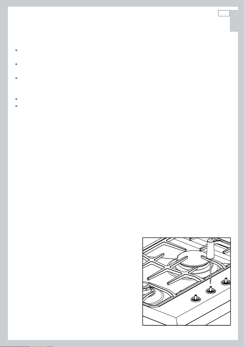
Minimum setting or turn-down
After installation check the minimum setting. This has been preset at the factory for NG but
needs to be checked and then reset if necessary. To adjust for minimum setting (if applicable),
you will need a Ø
(A suitable screwdriver is available as Fisher & Paykel spare part FB200467).
1
Ignite the burner and set the dial to its minimum position.
2
Remove the dials.
3
Rotate the turn-down screw (down the hole in the
spindle) while holding the shaft. Rotate slowly until
a minimum regular flame is achieved. (The flame
will diminish when the screw is turned clockwise and
increase when turned counter-clockwise).
4
When the setting is right, check regulation by quickly
rotating the dial from the maximum to the minimum
delivery position. The flame must not go out and the
auto-reignition should not click. Replace the dial.
⁄ “ x 1 ¾ ” (Ø 2.5 x 45 mm) screwdriver.
Fig.6 Minimum setting adjustment
US
CA
EN
16
Installation instructions
Checking the gas type
Burners NG Orifice
(mm)
NG
BTU (MJ/h) @
0.15 psi (4” W.C.)
RH Rear (Rapid)
LH Rear (Semi-rapid)
RH Front (Auxillary)
LH Front (Rapid)
CG365C Center (Wok)
CG365D Center (Wok)
1.3 mm 8,000 (8.4 MJ/h) 0.8 mm 8,200 (8.7 MJ/h)
1.1 mm 5,800 (6.1 MJ/h) 0.7 mm 5,700 (6.0 MJ/h)
0.85 mm 3,000 (3.2 MJ/h) 0.55 mm 3,500 (3.7 MJ/h)
1.3 mm 8,000 (8.4 MJ/h) 0.8 mm 8,200 (8.7 MJ/h)
1.75 mm 14,000 (14.8 MJ/h) 1.05 mm 13,000 (13.7 MJ/h)
2.15 mm 20,000 (21.1 MJ/h) 1.22 mm 19,000 (20 MJ/h)
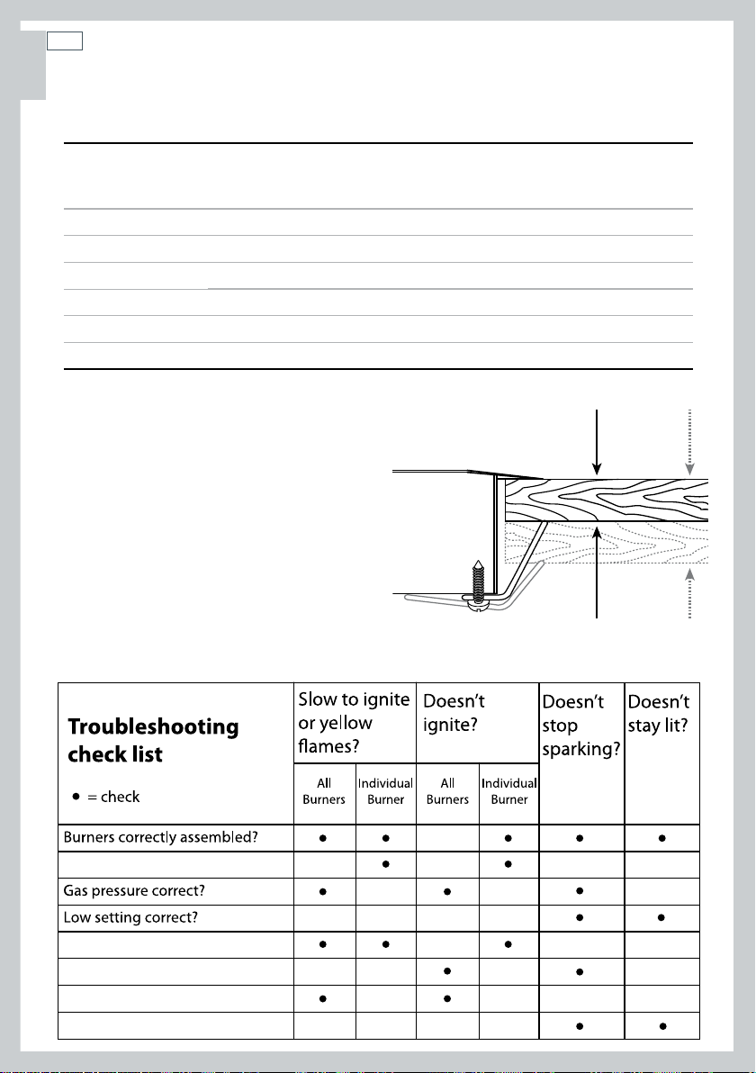
Clamping down the cooktop
Place the cooktop into the cutout and tighten it
with the supplied clamps. These will cope with
the countertop thicknesses
when used in the two orientations shown.
Do not over tighten.
¾ ”- 2” (19 - 50 mm)
LP Orifice
(mm)
LP
BTU (MJ/h) @
0.41psi (11” W.C.)
3
/4” - 2”
(19 mm - 50 mm)
Dirty ignitors?
Injectors incorrect or blocked?
Power supply polarity/grounding OK?
Supply voltage OK?
Draft/extraction? (advise the customer)
 Loading...