

Page 1

Integral Kit
Instructions
For Fisher & Paykel
Cabinet widths of
635, 680, 790 mm wide
ActiveSmart Models
Version 6
Manual 844063
Updated September 2015
Page 2

2
Parts supplied with Built in Kit – part number 814990
Part
Qty
Description
Part no.
4
Rail slide
880791
4
Bracket slide
880792
2
Foot integration
880793
8
Cap elliptical for foot integration
880794
2
Spacers 20mm
880795
10
Screw A: (#8X ¾ CSK POSI)
880796
8
Screw B: (#8X40 CSK POSI)
880798
4
Screw C: (#8X ½ PAN PH)
900373
1
Ventilation Grill
(not part of the kit –
order separately).
873917
Ventilation grill (Not part of the kit, order separately, recommended for integration of
790 wide models)
- -
Page 3
3
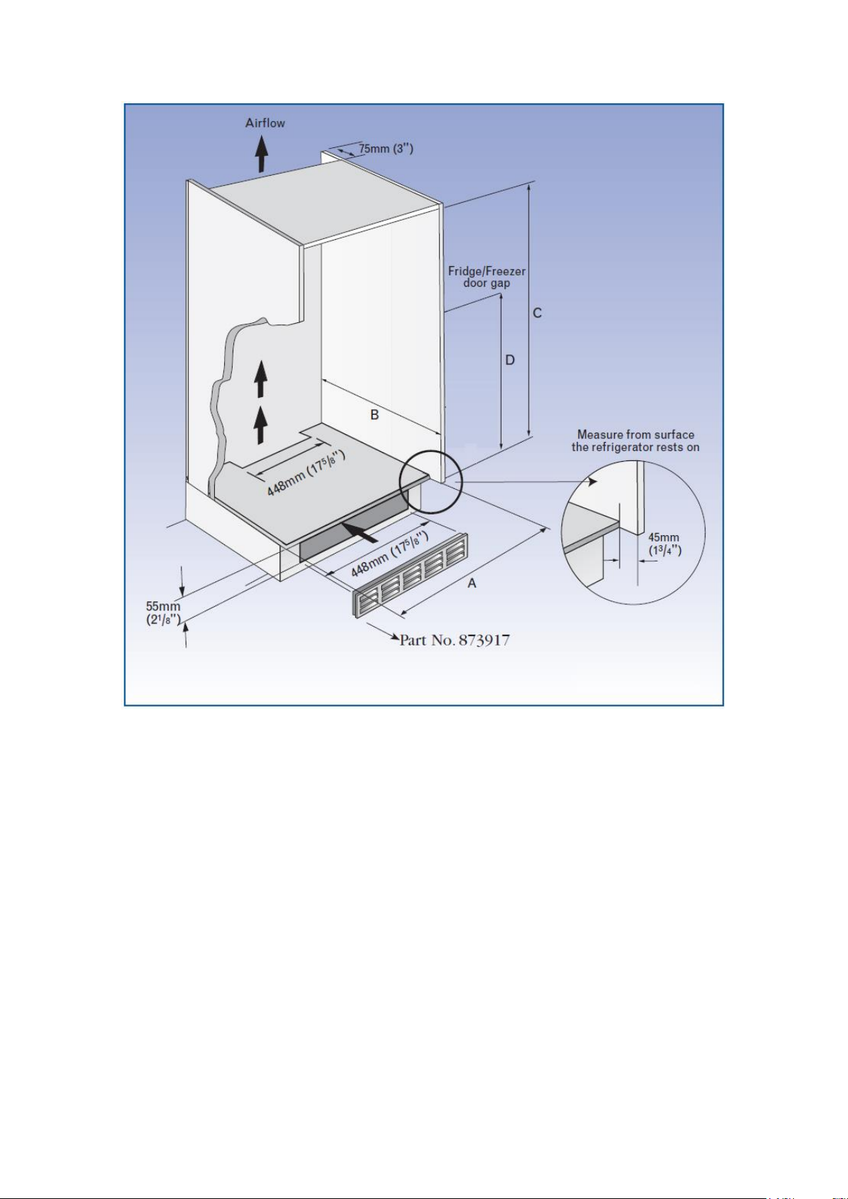
Installation dimensions
For Insert Doors add 30mm (2") to A and B
Cabinet Construction
IMPORTANT NOTICE
For a refrigerator to function to its optimum standard it requires a certain amount of air
clearance around the cabinet. With integration the cabinet is essentially sealed up. As
a result, the products energy, temperature and/or basic performance could be affected
as compared to a freestanding product.
If there are any issues with the products performance due to integration, this is at the
customers’ risk.
The base of the cabinet must be level- if not a shim may be required to lift the rear.
This diagram depicts the use of a ventilation grill. We recommend the use of this grill
when integrating 790 wide models. This grill is not included in this kit and can be
ordered as Part 873917.
- -
Page 4

4
Internal Dimensions
Model 635
Width (A)
Depth (B)
Height (C)
PC/FC
Centre line (D)
E331T, RF331T
735
730
1456
976
E373 / C373, E308
735
730
1456
E381T, RF381T
735
730
1626
1146
E372B, RF372B
735
730
1626
657
E411T, RF411T
735
730
1726
1245
E402B, RF402B
735
730
1726
657
E415H
735
730
1726
1245
E450 / C450, E388
735
730
1726
Model 680
Width (A)
Depth (B)
Height (C)
PC/FC
Centre line (D)
E413T
780
730
1616
1141
E406B
780
730
1616
652
E440T
780
730
1716
1240
E442B
780
730
1716
652
Model 790
Width (A)
Depth (B)
Height (C)
PC/FC
Centre line (D)
E521T
890
730
1716
1240
E522B
890
(35 1/32”)
730
(28 ¾”)
1716
(67 9/16”)
652
(25 11/16”)
Internal Dimensions width of the built in cabinet is as follows:
790/680/635 models
Cabinet internal width = Product width (790, 680 or 635) + 80mm (31/8") hinge side
and 20mm (3/4") door open side.
For height dimensions of the doors don't forget to take into account the thickness of the
material used in the floor and roof of the built in cabinet as the dimensions stated are
all internal.
Note: All dimensions shown are internal.
- -
Page 5

5
Hinges
Illustrated below are some of the types of hinging that can be used.
790, 680 & 635 Models
It is recommended that 110˚ hinges having a low profile are used, either full or half
overlay such as the GRASS brand. We recommend the use of hinges that can carry a
high load, especially when integrating 790 models.
- -
Page 6

6
1 Prepare Refrigerator for Installation
a) Check that the internal cupboard dimensions are correct (see page 4)
Unpack refrigerator protecting the floor and/or paint work from damage.
b) Check that refrigerator door is hinged on desired side. Refer to use & care
booklet for instructions to change hinge side.
Remove the door handles (refer to page 7).
Fit the door end cap blank to the corner of the door. Fit small plugs to the screw holes
left when the door handle was removed.
Using screw A, attach spacers to the side of the built in cabinet on the side without
hinges. They should be positioned approximately 100mm (4") from the top front,
150mm (6") from the front edge, and 75mm (3") rear corners of the refrigerator cabinet.
These spacers along with the foot integration bracket maintain an even gap of 20mm
(3/4") between the cupboard and the refrigerator side.
- -
Page 7

7
Flat Doors
Designer handles
1. Using a 4 mm Allen key remove the
grub screw from the underneath of the
handles.
2. Remove the handles.
3. Remove handle bosses.
How to remove refrigeration handles
Tilt the product back and remove the levelling foot circular base insert from the front
levelling feet, a small flat blade screw driver can be used.
Lift the product into the cabinet
- -
Page 8

8
Lift the front edge of the product and slide the integration foot under the levelling foot.
Push the product back to allow the outer cabinet door to close. This will be
approximately 95mm (3 3/4") from the front edge of the built in cabinet to the gasket
face of the refrigerator.
- -
Page 9

9
Align refrigerator in cupboard
Slide the product toward the opening side of the cupboard. The integrated foot should
touch the cupboard wall. This will set a 20mm (3/4") gap between cupboard and
refrigerator.
Adjust the product so it is parallel to the cabinet front to back and side to side.
This is obtained by the adjustment of the front levelling feet.
WARNING: Please be advised that adjustment of glass shelves is not possible
once the refrigerator has been integrated.
- -
Page 10

10
Attach slide bracket to refrigerator doors
Attach the slide bracket to the side of the door opposite to the hinges, 100mm (4") in
from the edge.
On a two door refrigerator use one slide bracket per door. If integrating a 790 model,
we recommend using 2 slide brackets per door - one near the bottom of the door & one
near the top of the door to evenly distribute the weight. The brackets should be
attached to the opening side of the doors near the refrigerator and freezer
compartments.
On a single door refrigerator use one slide bracket at each end of the door.
Screw brackets firmly into the steel door face using countersunk screw B.
- -
Page 11

11
Attach slide bracket to cupboard door
a) Open both cupboard and refrigerator
door to 110˚ degrees. (525 compact
models to 90˚)
b) Put slide bracket in retainer, 120mm
(43/4") approx past refrigerator door.
(diagram 9).
c) Check that screw A (supplied with kit)
will not penetrate front surface of
cupboard door (diagram 10).
d) Screw slide bracket level into the
cupboard door using screw A
(supplied with the kit)
e) Check slide mechanism does not bind
through swing of door.
f) Repeat for second bracket.
IMPORTANT
Ensure that refrigerator doors are able to close fully and seal around the flexible gasket
on the refrigerator/freezer. This is to prevent air leaks and icing problems
Complete Installation
a) Complete the installation by screwing the foot integration into position, using screw
(D) (supplied with the kit), and the cap elliptical to cover the screws.
- -
 Loading...