

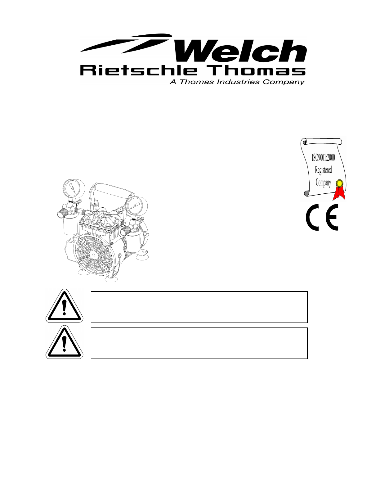
OWNER’S MANUAL
FOR
WOB•L® PISTON
PRESSURE/VACUUM PUMPS
MODELS:
2534C-02 & 2546
Contents: Safety Information
Installation
Operation
Maintenance
Trouble-Shooting Guide
Specifications
Warranty
Parts List and Exploded View
WARNING
Not recommended for pumping acid, base or organic
vapors or gases.
WARNING
Be sure to properly identify intake and discharge
before using pump. See Section 3.50
Welch Rietschle Thomas
7301 North Central Avenue
Skokie, IL 60077
Phone: (847) 676-8800
Fax: (847) 677-8606 (Technical Support)
Fax: (920) 451-4397 (Ordering)
E-Mail: welchvacuum@thomasind.com Part No. 67-1476R1.0
Web-Page: www.welchvacuum.com Printed in USA
INSTRUCTION
WARNING AND CAUTION
PLEASE READ BEFORE OPERATION
While reading your manual, please pay close attention to areas labeled:
WARNING AND CAUTION.
The description of each is found below.
WARNING
Warnings are given where failure to observe instruction could result in
injury or death to people.
CAUTION
Cautions are found where failure to observe the instruction could result
in damage to the equipment, associated equipment and process.
These units confirm to the SI International system of units of measurement.
The following symbols (with recommendation of IEC1010 ) of warning will be found on the pump.
Caution - refer to accompanying documents
Caution - risk of electrical shock
Caution - hot surface
WARNING
Motor includes a self resetting thermal cutout and the pump could
restart without actuation under fault condition.
2

TABLE OF CONTENTS
Section 01 SAFETY INFORMATION
Section 02 CAUTION TO REDUCE RISK
Section 03 INSTALLATION
Section 04 ELECTRICAL POWER
Section 05 TRAPS
Section 06 OPERATION
Section 07 MAINTENANCE
Section 08 TROUBLESHOOTING
Section 09 SPECIFICATION
Section 10 WARRANTY
Section 11 EXPLODED VIEW AND PARTS LIST
3

Welch Rietschle Thomas
Read and understand the following information and instructions included with your Welch Dry Dual Function Pressure
&Vacuum Pumps before using. This information is for your safety and to prevent damage to the pumps.
Section 01 SAFETY INFORMATION
1.10 CAUTION TO PREVENT INJURY...
1.11 Never operate this product if it has a damaged cord or plug. If it is not working properly has been dropped damaged
or has fallen into water, please return the product to a Welch service center for examination and repair.
1.12 Keep the cord away from heated surfaces.
1.13 Never block any air openings or place it on a soft surface where the openings may be blocked. The air openings are
for ventilation of the motor inside the housing. Keep all air openings free of lint, dirt, and other foreign objects.
1.14 Never drop or insert fingers or any other object into any openings.
1.15 D o not operate this product where oxygen is being administered.
1.16 This pump is thermally protected and can automatically restart when the protector resets. Always disconnect power
source before servicing.
1.17 Wear safety glasses or goggles when operating this product.
1.18 Use only in well ventilated areas.
1.19 D o not use any tools or attachments without first determining maximum air pressure for that tool or attachment.
1.20 Never point any air nozzle or air sprayer toward another person or any part of the body.
1.21 All electrical products generate heat. To avoid serious burns never touch unit during or immediately after operation.
1.22 B e sure to properly identify intake and discharge before using pump. See Section II-5.
Section 02 CAUTION TO REDUCE RISK
2.10 WARNING: TO REDUCE RISK OF ELECTRICAL SHOCK…
2.11 D o not disassemble. Disassembly or attempted repairs if accomplished incorrectly can create electrical shock
hazard. Refer servicing to qualified service agencies only.
2.12 Unit is supplied with a three pronged plug Be sure to connect pump to a properly grounded outlet only.
2.20 WARNING: TO REDUCE RISK OF ELECTROCUTION…
2.21 D o not use this product in or near area where it can fall or be pulled into water or other liquids.
2.22 D o not reach for this product if it has fallen into liquid. Unplug immediately.
2.23 Never operate this product outdoors in the rain or in a wet area.
2.30 DANGER: TO REDUCE RISK OF EXPLOSION OR FIRE…
2.31 D o not use this pump in or near explosive atmospheres or where aerosol (spray) products are being used.
2.32 D o not pump anything other than atmospheric air.
2.33 D o not pump combustible liquids or vapors with this product or use in or near an area where flammable or explosive
liquids or vapors may exist.
2.34 D o not use this product near flames.
FAILURE TO OBSERVE THE ABOVE SAFETY PRECAUTIONS COULD RESULT IN SEVERE BODILY
INJURY, INCLUDING DEATH IN EXTREME CASES.
4

Section 03 INSTALLATION
3.10 INTRODUCTION This manual has been compiled not only for the care and maintenance of the Welch Dry Dual
Function Pressure/Vacuum pump now in your possession, but as a helpful reference and guide to prevent many problems
which can occur if used improperly.
3.20 UNPACKING Carefully remove the Pressure/Vacuum pump from the shipping case and unfasten and remove
the wooden skid. Preserve all paperwork for future reference. If damage has occurred from shipment a claim must be filed with
the carrier immediately; preserve the shipping carton for inspection by the carrier. If you are required to communicate with
your dealer or Welch Vacuum, be sure to include your order numbers for quick identification. Do not return the pump to the
factory without first calling for a returned goods number.
3.30 PUMP MOUNTING Rubber feet are attached to the pump. Rubber feet are excellent for applications involving a semi-
flexible surface such as a bench top; they help to isolate noise and eliminate creeping. All Pressure/Vacuum pumps should he
mounted on a
3.40 PUMP LOCATION The pressure/vacuum pump should be located preferably in a clean, dry, and well ventilated area.
Please be sure not to block the ventilation holes located on the motor housing. The pump should be placed where the
surrounding temperature remains between 10°C and 40°C (50°F and 104°F). Always check to insure the location chosen is
protected from direct or indirect moisture contact. Welch recommends that the pump be installed at the highest point within
the system to prevent possible water condensate from entering the pump. The pump should be located as closely to its
system in order to utilize it most efficiently.
The motor is thermally protected and will automatically restart unexpectedly when
the overload device resets. Don’t pump flammable or explosive gases or vapors or operate
this pump in an atmosphere containing flammable or explosive gases or vapors.
3.50 INTAKE AND DISCHARGE PROVISIONS Two regulators and two gauges make it easy to meet your vacuum
and pressure requirements. The vacuum regulator and vacuum dial gauge is attached to the intake port. The vacuum
regulator allows the vacuum level to be set between roughly atmospheric pressure and the maximum vacuum allowed for the
pump model. A moisture trap keeps water from accidentally being drawn into the unit.
The pressure regulator and pressure dial gauges are attached to the discharge port. The pressure regulator allows discharge
pressure to be set between atmospheric and the maximum possible for the pump model. Discharge air is filtered and noise is
muffled with a filter.
Note: Adjusting either the pressure or vacuum regulators will affect the performance of the pump.
PROPERLY IDENTIFY THE INTAKE AND
DISCHARGE OF THE PUMP
Intake Discharge
Pressure/Vacuum Pump
Never Block The Discharge Port. If the exhaust is blocked, pressure will build- up in the
pump above its rated operating pressure. Be sure to call Welch technical service prior to
start-up at (847) 676-8800 if you have any questions.
5

Section 04 ELECTRICAL POWER
4.10 Power Source Review Review the power source and the motor rating to be sure they agree in voltage, phase,
and frequency. Serious damage may occur to the motor if it is connected to an improper voltage. All Welch pumps must be
grounded. Grounding reduces the risk of electric shock in the event of an electrical short circuit. The plug must be plugged
into a properly grounded outlet. Consult your local electrical codes if you have doubts.
4.11 Overload Protection Motor thermal overload protection is made available by the motor manufacturer as anaid
to minimize motor failure.Overload protection is a standard feature on both 50 and 60 Hz single-phase-motors. The motors
have automatic overload protection. Automatic reset protection is designed to reset itself after a predetermined cooling
period. If the fault to the drive remains unaltered, the motor will cycle on and off until the fault is corrected.
4.20 VACUUM CONNECTIONS All pressure/vacuum pumps come with intake and discharge hose barbs which accept
1/4" ID rubber pressure/vacuum hose. Hose clamps should be used to hold the hose in place. Since all three models operate
in the viscous flow regime, the small diameter of the hose will generate minimal conductance loss. For best results, Welch
recommends the length of the tubing between the pump and the chamber be kept as small as possible.
4.21VACUUM AND PRESSURE GAUGES All models of pressure/vacuum pumps come with dial gauges mounted on the
regulator assemblies. The vacuum gauge gives negative pressure - that is pressure below atmospheric. The reference point
for the vacuum gauge is atmospheric pressure.
The pressure gauge gives pressure above atmospheric. The reference point for the pressure gauge is atmospheric pressure.
Please keep in mind that atmospheric pressure tends to vary from day to day. As a result of this variability, the dial vacuum
gauge will indicate slightly different maximum vacuum readings from day to day.
Section 05 TRAPS
5.10 The need for a Trap The pumps will handle humid air. All wetted aluminum parts are treated for corrosion protection
from moisture. All other wetted parts are stainless steel. A plastic trap with a ball check valve is attached to the regulator
assembly to prevent water condensate from accidentally being ingested into the pump. If there is a chance liquid may be
drawn from the process under evacuation, Welch recommends a liquid trap be placed between the process and the pump. A
simple liquid trap is a filtering flask. See figure below.
When a heavy load of water vapor is evolved from the vacuum process, a cold trap is recommended to help prevent damage
to the pump mechanism. The cold trap, immersed in a suitable Dewar flask, is installed so that the water vapors may come in
contact with the surfaces of the trap and condense. Commonly used refrigerants are liquid nitrogen or dry ice and acetone or
alcohol. Dry ice provides sufficient cooling to freeze out most heavy water vapor loads. A variety of cold traps are available
from Welch. Please call our customer service department for additional information at (847) 676-8800.
The pump is not recommended for pumping acid, base or organic vapors or gases. Serious
damage to the pump will shorten the pump’s service life. In addition, pumping flammable
vapors or gases can lead to serious safety hazard leading to fire or explosion.
6

5.11 The Care of a Trap When using a cold trap the refrigerant should be maintained at a high level in the flask to keep the
trap at a uniformly low temperature. If the trap is rewarmed it may allow re-evaporation of the condensate. The refrigerant add
tube on the liquid nitrogen trap should not be obstructed as the refrigerant boil-off can pro- duce dangerously high
pressures. If the trap becomes saturated it should be disconnected from the system, drained, and cleaned. An increase in
pressure in the vacuum system will normally indicate that the trap has become saturated. To clean the trap, remove the trap
from the system and allow the trap to warm up and rinse off the condensate with a suitable solvent in a fume hood.
Thoroughly clean and dry the trap before reinstalling into the system.
Section 06 OPERATION
6.10 Starting A Welch Pressure/Vacuum Pump Before attaching the pump to a system, familiarize yourself with the
function and action of the pressure/vacuum pump that you have acquired. Review the power requirements as described in
Section l-6. Welch recommends running the pump for a few minutes to warm it up, before use. The warm-up improves the
pumps ability to handle humid air.
6.11Cleanliness Take every precaution to prevent foreign particulates from entering the pump. Particulates will damage the
pump’s performance. If you find that particulates come off the process during evacuation, a particulate trap in the foreline
will work. A simple, inexpensive trap may be made by placing glass wool in a glass or plastic tube. Screens must be inserted
to hold the glass wool in place.
6.20 LEAK DETECTION The importance of eliminating all leaks in a vacuum system is obvious. The pump must remove
this added volume of leaked gas to maintain the desired vacuum. Leaks for these pump can be located by slightly pressuring
the system and painting the suspected area with a thick soap solution. Escaping air will produce soap bubbles.
6.30 OPERATING PRESSURE RANGE Pressure/Vacuum pumps are designed to be run from slightly below atmospheric
to their maximum vacuum level on the intake side. The pumps also may be run from atmospheric to their maximum rated
pressure rating. Consult the Specification Table (See Section VI, Specifications) for the ratings of your specific model.
6.40 SHUTDOWN PROCEDURES After use, Welch recommends the pump be run for about 2 minutes disconnected from
the vacuum process. The air pumped through the mechanism will purge out water vapor or droplets of water condensate that
may have formed on the inside of the pump. This purge of the pump mechanism helps prevent corrosion.
Section 07 MAINTENANCE
Welch dry pressure\vacuum units are 100% oil-free. The pump employs a non-lube piston and cylinder. No maintenance is
necessary for the bearings. All bearings are sealed and permanently lubricated. Lubrication should not be attempted. The
units are built for continuous duty operation with the quietness and durability of a diaphragm, but with piston performance.
7

Section 08 TROUBLESHOOTING
8.10 VACUUM PROBLEMS Leakage, contamination, and unusual outgassing are the general causes of problems
associated with poor vacuum. To operate at maximum efficiency, a system must be thoroughly clean. It the system is
completely clean and free from leaks, and unwarranted vacuum problems still exist, the pump should be checked. A simple
criterion for the condition of the pump is the determination of its maximum vacuum capability. This can be accomplished by
blocking of the intake and reading the vacuum level on the gauge (See Section II-8).
8.20 PRESSURE PROBLEMS Leakage and contamination are the general causes of problems associated with poor
pressure. To operate at maximum efficiency a system must be thoroughly clean. If the system is completely clean and free
from leaks, and unwarranted pressure problems still exist, the pump/compressor should be checked by a service technician.
(See Section II-8).
8.30 TROUBLESHOOTING GUIDE
Poor Pumping
Speed
X X X Damaged Valves Replace flap pe r valves
X X X Debris in Valves
X X X Damaged Gaskets Replace gaskets
X X X Loo se Head Screws Tig hten head screws
X X Loose Fittings Tig hten fi ttings
Poor
Pressur e
Loud Unit Possible Cause Corrective Action
Remove debris and check
Section 09 SPECIFICATION
ledoMhcleW43526452
tnemecalpsiDriaeerF
zH06@)nim/L(MFC
zH05@)nim/L(MFC
)lacsaP(GISP.sserP.tnoC.xaM001001
)rroT(gH.ni,muucaV.xaV)59(2.62)76(3.72
rewopesroHrotoM7/13/1
.ni.D.I,dedeeNgnibuT4/14/1
)gkI.sbl,thgieW)3.5(7.11)3.6(8.31
rebmuNgolataC
rebmuNgolataC
rebmuNgolataC
gulP)okuhcS(oruEhtiw
rebmuNgolataC
gulPV052oruEhtiw
esahP1,zH06,V511rofderiW
gulPV511naciremA.Nhtiw
esahP1,zH06,V032rofderiW
gulPV511naciremA.Nhtiw
esahP1,zH05,V022rofderiW
esahP1,zH06,V032rofderiW
for valve damage
)43(2.1
)82(0.1
10-B435110-B6452
10-C435210-C6452
20-C435220-C6452
--
)54(6.1
)73(3.1
Note: **50 Hz models provided with CE mark.
8

Section 10 WARRANTY
UNPACKING
Inspect the pump carefully. If any damage has occurred, file claim with the carrier immediately. Save the shipping container for
carrier to inspect.
OPERATING PUMP
Refer to the enclosed Instruction/Operation Manual for all information to properly operate and maintain the pump.
WARRANTY
This Welch Vacuum product is warranted to be free from defects in material and workmanship. The liability of Welch
Rietschle Thomas under this warranty is limited to servicing, adjusting, repairing or replacing any unit or component part
which in the judgment of Welch Rietschle Thomas has not been misused, abused or altered in any way causing impaired
performance or rendering it inoperative. No other warranties are expressed or implied. The method of executing this warranty:
servicing, adjusting, repairing or replacing shall be at the discretion of Welch Rietschle Thomas. Vacuum pumps that have
been used for any period, however short, will be repaired under this warranty rather than replaced.
The warranty is effective for one year from the date of original purchase when:
1. The warranty card has been completed and returned.
2. The product is returned to the factory or other designated service centers, freight prepaid.
3. The product in our judgment is defective through no action or fault of the user.
If the product has become defective through misuse, abuse, or alteration, repairs will be billed regardless of the age of the
product. In this event, an estimate of the repair costs will be submitted and authorization of these charges will be required
before the product is repaired and returned.
To reduce additional charges and delays either within or outside of the warranty period, contact Welch Rietschle Thomas
@847-676-8800 for a return authorization number. Products without a return authorization number will be refused by our
receiving department. Before shipping, properly pack the pump, insure it against loss or damage, and on the outside of
the pump packaging and the packing slip write in the return authorization number. Pumps damaged due to improper
packaging are the customer’s responsibility.
9

Section 11 EXPLODED VIEW AND PARTS LIST
11.10 DRAWING AND PARTS LIST FOR 2546
Seal
Item
Number QTY Part Number Description
1 1 2546K-01 Connecting Rod Assembly 1
3 4 Note 1 Head Screw 4
4 1 Note 1 O-Ring Head 1 1
5 1 2567K-02 Valve Plate Ass embly 1
6 1 Note 1 O-Ring Cylinder 1 1
7 2 Note 1 Jar Plastic 1 1
8 1 Note 1 Filter Element 1 1
9 1 71-1292 Pressure Gauge
10 1 Note 1 Ball 1 1
11A 1 71-1295 Vacuum Gauge 2546B-01
11B 1 71-1296 Vacuum Gauge 2546C-02
12 2 Note 1 Gasket 1 1
13 4 Note 1 Rubber Suction Feet 4
14 1 2522K-06 Pressure Regulator Assembly
15A 1 2522K-05 Vacuum Regulator Ass embly 2546B-01
15B 1 2522K-07 Vacuum Regulator Ass embly 2546C-02
16 1 Note 1 Piston Cup Seal 1
17 1 Note 1 Retainer Screw 1
Service Kit
2546K-03
Service Kit
2546K-04
10
Feet
Service Kit
2500K-04

11.20 DRAWING AND PARTS LIST FOR 2534C-02
Seal
Item
Number QTY Part Number Description
1 1 2534K-10 Connecting Rod Assembly 1
3 4 Note 1 Head Screw 4
4 1 Note 1 O-Ring Head 1 1
5 1 2567K-02 Valve Plate Ass embly 1
6 1 Note 1 O-Ring Cylinder 1 1
7 2 Note 1 Jar Plastic 1 1
8 1 Note 1 Filter Element 1 1
9 1 71-1292 Pressure Gauge
10 1 Note 1 Ball 1 1
11B 1 71-1296 Vacuum Gauge 2546C-02
12 2 Note 1 Gasket 1 1
13 4 Note 1 Rubber Suction Feet 4
14 1 2522K-06 Press ure Regulator Assembly
15B 1 2522K-07 Vacuum Regulator Ass embly 2546C-02
16 1 Note 1 Piston Cup Seal 1
17 1 Note 1 Retainer Screw 1
Service Kit
2534K-03
Service Kit
2546K-04
11
Feet
Service Kit
2500K-04

Welch Rietschle Thomas
7301 N. Central Ave.
Skokie, IL 60077
Phone: (847) 676-8800
Fax: (847) 677-8806
OWNER’S MANUAL
For
WOB•L® PISTON PRESSURE/VACUUM PUMPS
MODELS 2534C-02 & 2546
Part No. 67-1476R1.0
Copyright© 1997-2004 Welch Rietschle Thomas
Welch is a registered trademark of Welch Rietschle Thomas
P/N 642517 C 05/04
 Loading...