

Page 1
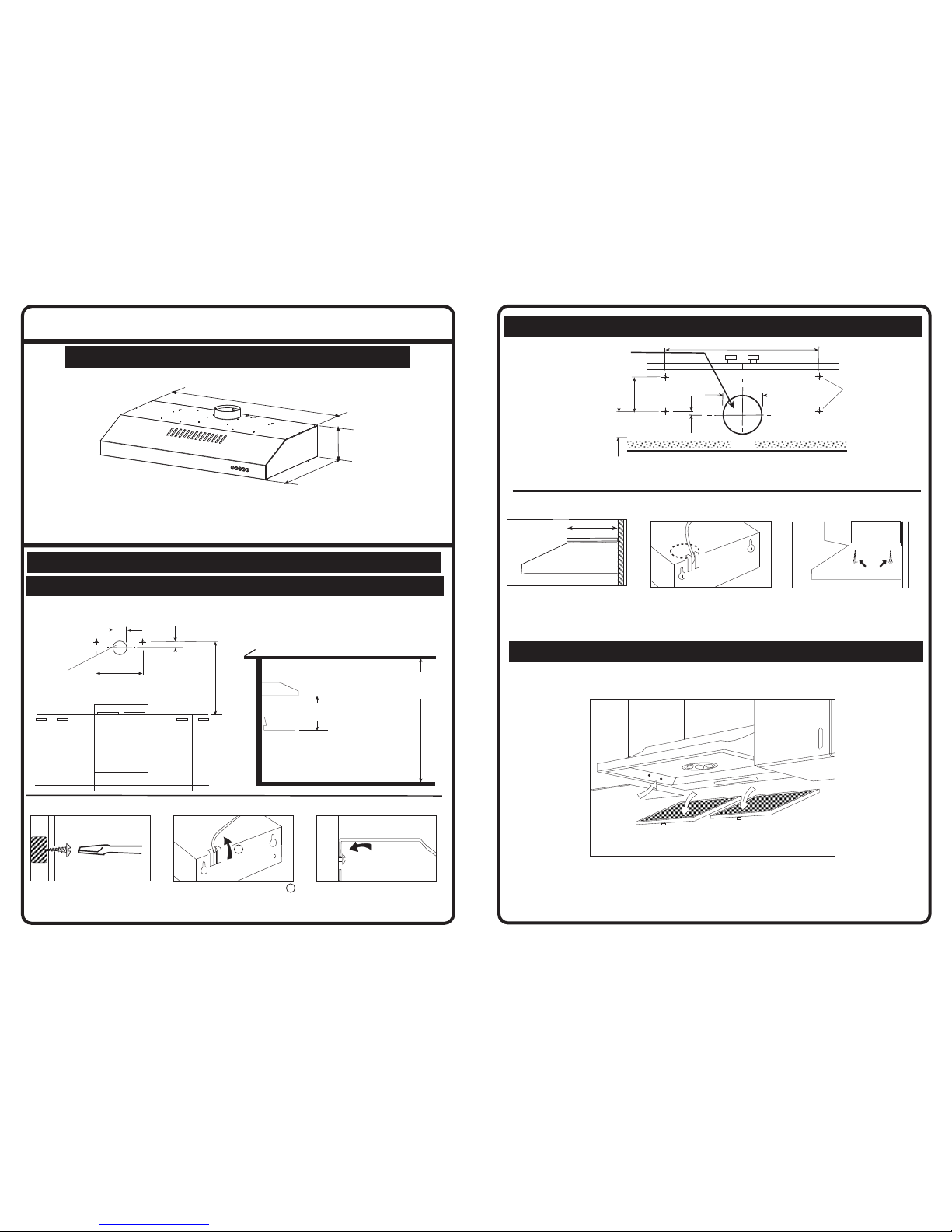
WALL MOUNTING
INSTALLATION INSTRUCTION
RANGEHOOD
Note: Generic model is shown.
Actual product may differ.
PLEASE READ THE ENTIRE INSTRUCTION BEFORE INSTALLING THE RANGEHOOD
ALL DIMENSIONS IN MM
MOUNTING OPTIONS
MOUNTING TO REAR WALL
HOOK RANGEHOOD ONTO THE
SCREWS. FIT THE TWO BOTTOM
SCREWS THROUGH THE HOLES
INTO THE PREDRILLED HOLES.
SWIVEL POWER OUTLET TO TOP
2
2
DRILL HOLES AND MOUNT TWO
TOP SCREWS AS SHOWN
REFER WALL MOUNTING DETAIL
If using Uniduct
cut outside wall
hole Dia 135mm
600-800mm
For Gas 650-800mm
2.4M
CEILING
HEIGHT
STOVE
130
500
MODEL 600
MODEL 900
For rear
ducting cut hole
to suit duct size.
Dimensions
shown
are for Uniduct
36
732
to
932
STOVE
490
152
598 (600)
898 (900)
SCREW
THROUGH
SIDES USING
HOLE POSITIONS
INDICATED
REMOVE FILTERS
DRILL FOUR HOLES AT
POSITIONS INDICATED,
REFER UNDER CUPBOARD
MOUNTING
MOUNTING UNDER
CUPBOARDS
SWIVEL POWER OUTLET TO T OP .
CUT HOLE IN CABINET TO SUIT
FIT THE TWO REAR SCREWS
FIT THE UNIT OVER THE SCREWS
FIT THE TWO FRONT SCREWS
305mm
INNER CUPBOARD MOUNTED
SIDE WALL MOUNTING
UNDERCUPBOARD MOUNTING
Underside View of Cupboard
For top ducting cut hole
to suit duct size.
Dimensions shown are
for Uniduct
500 (600&900)
90
165
Drill
5mm
holes
Wall
130
20
ECN: 05 171
111007 Issue C
Page 2
111007 Issue C
ECN: 05 171
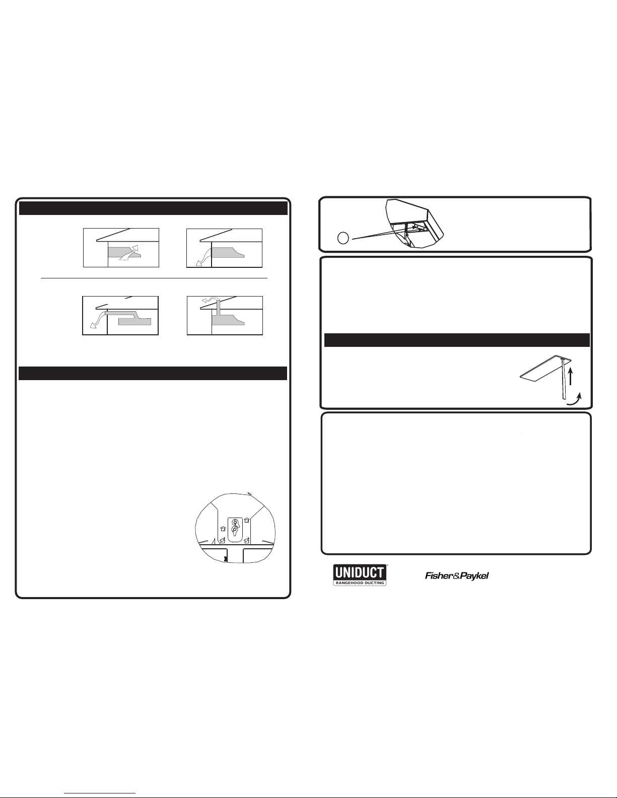
DUCTING OPTIONS
TOP DUCTED
NOTE: when ducting
Exhaust air must not be discharged into any chimney or flue which may carry combustion
products from other sources. In addition, exhaust air must not be discharged into a wall
cavity, unless designed for the purpose.
OPERATION & CLEANING
OPERATION
After your Rangehood is fixed in position:
1. Check that the light and the diffuser are in place.
2.
This unit is fitted with a recirculating duct and cover. If the unit is rear or top ducted this
3. Remove protective plastic covering from the filters.
See that the filters are correctly positioned.
4. Plug into 230-240V outlet. Keep cord clear of stove elements or hot utensils.
Permanent wiring to house supply, or modifications to plug or wire should be
carried out by a registered electrician.
BOTTOM VIEW
DUCTED OR RECIRCULATION
To adjust this unit to the required airflow direction
proceed as follows.
1. Remove the filters and look up at the bottom
of the unit. A view similar to the sketch is seen.
2. The unit should be factory set in the ducted
position shown. Should a recirculation mode
be required, rotate both levers to the symbol
representing recirculation.
3. Remove the screw holding the vent cover and
slide the cover open, re secure the vent cover using
in screws.
4. Replace the filters.
CLEANING
1.Disconnect the Rangehood from power supply.
2. Wash aluminium filters every 2 or 3 months, depending on usage, with hot
soapy water or in the dishwasher.
3. Charcoal filters should be replaced every three to six months depending
on use.
4. Clean the external and internal surfaces, using a damp cloth and mild
detergent. Do not use any powder or abrasive cleaners.
1.Disconnect the Rangehood from power supply.
2. Insert small screwdriver or slim knife as shown,
ease catch to side and slip out the diffuser.
3. Replace lamp (40 watt max).
4. Slide diffuser back into aperture and ‘click’ into
place.
LAMP REPLACEMENT
WARNING
• This appliance is not intended for use by young children or
infirm persons without supervision.
•Young children should be supervised to ensure that they do
not play with the appliance.
• There shall be adequate ventilation of the room when the
rangehood is used at the same time as appliances burning gas
or other fuels.
• You must read the details concerning the method and frequency
of cleaning.
• There is a fire risk if cleaning is not carried out in accordance
with the instructions.
• Do not flambé under the rangehood.
• Exhaust air must not be discharged into an existing flue which
is used for exhausting fumes from appliances burning gas or
other fuels.
• The minimum distance between the hob surface and the lowest
part of the rangehood is 600mm. This distance shall be at
least 650mm , if the rangehood is installed over a gas hob.
(We recommend 700mm)
•Attention should be given to ensure that any applicable
regulations concerning the discharge of exhaust air are fulfiled
• If the supply cord of this equipment is damaged, it must only
be replaced by the manufacturer or its service agent or similarly
qualified person in order to avoid a hazard.
Electrical Rating:
484.8W (2.02A)
Max. at 230-240V 50Hz
VENT COVER
FIXING SCREWS
1
REAR DUCTED
RECIRCULATING
COVER DISC
IN TOP PORT
FLEXIBLE DUCT
PLACE ROUND COVER DISC
IN REAR PORT
COVER DISC
IN REAR PORT
cover should be closed. If the unit is in recirculating mode it should open
To adjust this cover, remove the filters and the two screws attaching the cover to the recirculation
duct,arrow 1 (See oppsite page). Slide the cover as desired, to allow the slots to open or close.
Reattach the cover to the recirculation duct with the screws.
MANUFACTURED FOR
BY:
ROBINHOOD LIMITED
6 ZELANIAN DRIVE, EAST TAMAKI
AUCKLAND, NEW ZEALAND
ISO9001 Certified
RECOMMENDED UNIDUCT DUCTING
SYSTEMS FOR RANGEHOODS
 Loading...