

Page 1
F9 Diagnostic Manual
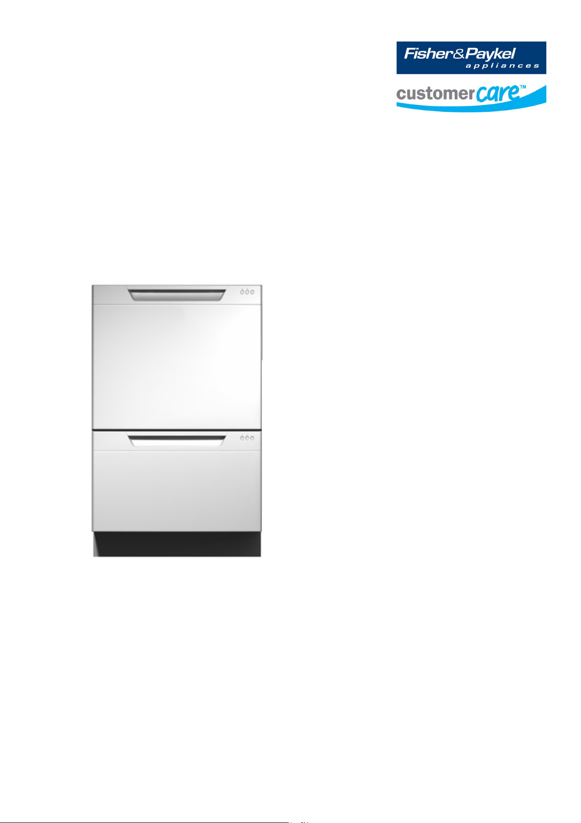
DishDrawer™ Ph5 & 6
590241
1
Page 2
Brand: Fisher & Paykel
DCS
MODELS MARKETS
DD605/DS605 NZ, AU, UK, EU, DK, US,CA
DD60 NZ, AU, UK,EU, DK,
DD90 NZ, AU, UK,EU,DK
DD24 US, CA
DD36 US, CA
2
Page 3

CONTENTS
1 FAULT FINDING PROCEDURE ............................................... 4
2 F9 FAULT CODE....................................................................... 5
3 CONTROLLER TYPES ............................................................. 5
4 CHECKING SPECIFIC COMPONENTS ................................... 6
4.1 Component Checking Procedure....................................... 8
5 DIAGNOSTICS........................................................................ 16
5.1 DishDrawer Diagnostics...................................................16
5.1.1 Display Mode – Level One......................................................16
5.1.2 Hardware Output Test Mode – Level Two...............................17
5.1.3 Fast Test Cycle – Level Three ................................................18
5.1.4 Continuous Cycle Test Mode – Level Four..............................19
6 WIRING DIAGRAM ................................................................. 20
3
Page 4

1 FAULT FINDING PROCEDURE
Before beginning, determine if the controller fitted is a PH5 or PH5.1 controller, as the fault finding procedure is slightly
different for each (See Section 3 - Controller Types).
1. If it is a double product, one tub will be displaying an F9 and the other will most likely be displaying U4. The
U4 indicates that the F9 fault on the other tub means that the U4 tub cannot operate. DO NOT replace the
controller with the U4 fault.
2. Disconnect then reconnect the power to the product at the wall socket. Wait 20 seconds after power up, if a
tub faults F9 in this time then go to Step 3, otherwise skip to Step 5.
3. On the tub with the F9, check the following:
a. Check that the harnesses are completely connected and there is no contamination in the connector -
Especially the ‘POWER’ and ‘DISPENSER’ connections.
b. Measure the resistance of the power resistor (See Section 4.1)
c. Measure the resistance of the detergent diverter (See Section 4.4)
If any components are faulty, replace and go back to Step 2. If all of these components appear OK, go to Step
4.
4. Before replacing the controller, ALL components need to be measured to determine if they are faulty.
a. Measure the resistance of all other components (coils, windings etc) – Section 4.2 to 4.7. Replace
any faulty components before installing a new controller.
b. If on power up the product still produces an F9, check all connections between the chassis board and
controller, check the chassis board for signs of corrosion (See Section 4.9) and if required replace the
chassis board and/or harness.
Replace any faulty components, repeat Step 2 and if no F9 fault appears, go to Step 6.
5. ALL components need to be checked to determine if they are faulty.
5.1 Controllers:
a. Check each component individually in ‘HO’ mode (see Section 5 and 5.1.3).
b. Only run ONE component at a time, if after approximately 5 seconds a long, low tone is played then that
component is faulty or not connected. Reconnect or replace the component. In this case the controller
does NOT need to be replaced.
Note: To adequately test the motor there must be water in the tub.
c. If all components appear OK, and the product is a pre finished LCD model go to (e) if the product is a flat
door or integrated product, then replace the badge isolator.
5.0 Controllers:
a. Measure the resistance of all other components (coils, windings etc) – Section 4.2 to 4.7. If any
components are faulty, then replace the component.
b. Run the fan in ‘HO’ mode. If the fan exhibits poor performance (low air flow), replace the fan.
c. If (a) and (b) find faulty components, replace the controller and go to step 6. Otherwise go to (d).
Both 5.0 & 5.1 Controllers
d. Check the controller for signs of corrosion or burning. If any found, replace controller and harness
(if required) – See Section 4.8.
e. If turning off the bottom tub (power button) causes the top tub to fault F9, check the ‘CHASSIS’ harness
connections are tight (at controller and chassis board) and for chassis board dry joints before replacing
the chassis board – See Section 4.9.
As per Step 5, check all components individually in ‘HO’ mode (see Section 5 and 5.1.3) and then run a Fast
6.
Cycle (see 5.1.3) before leaving the site.
4
Page 5
2 F9 FAULT CODE
Display
Secondary Panel
Power Supply / Controller Fault
The product will disable power supply, log the fault, lock out the
user and report to the user via a fault code.
Note: The isolation relay will be disabled. Power to the product will
need to be disconnected then reconnected for it to become fully
functional again.
Once powered up, wait 20 seconds before trying to enter
diagnostics, as product will be doing a self check.
3 CONTROLLER TYPES
There are 2 versions of controller:
Phase 5 series controllers
Part Number Market
527715NAP NZ, AU
528793EUP GB, IE, EU
528356USP USA, CA
522946USP USA, CA
Phase 5.1 series controller
Part Number Market
522843NAP NZ, AU
522844EUP GB, IE, EU
522841USP USA, CA
5
Page 6
4 CHECKING SPECIFIC COMPONENTS
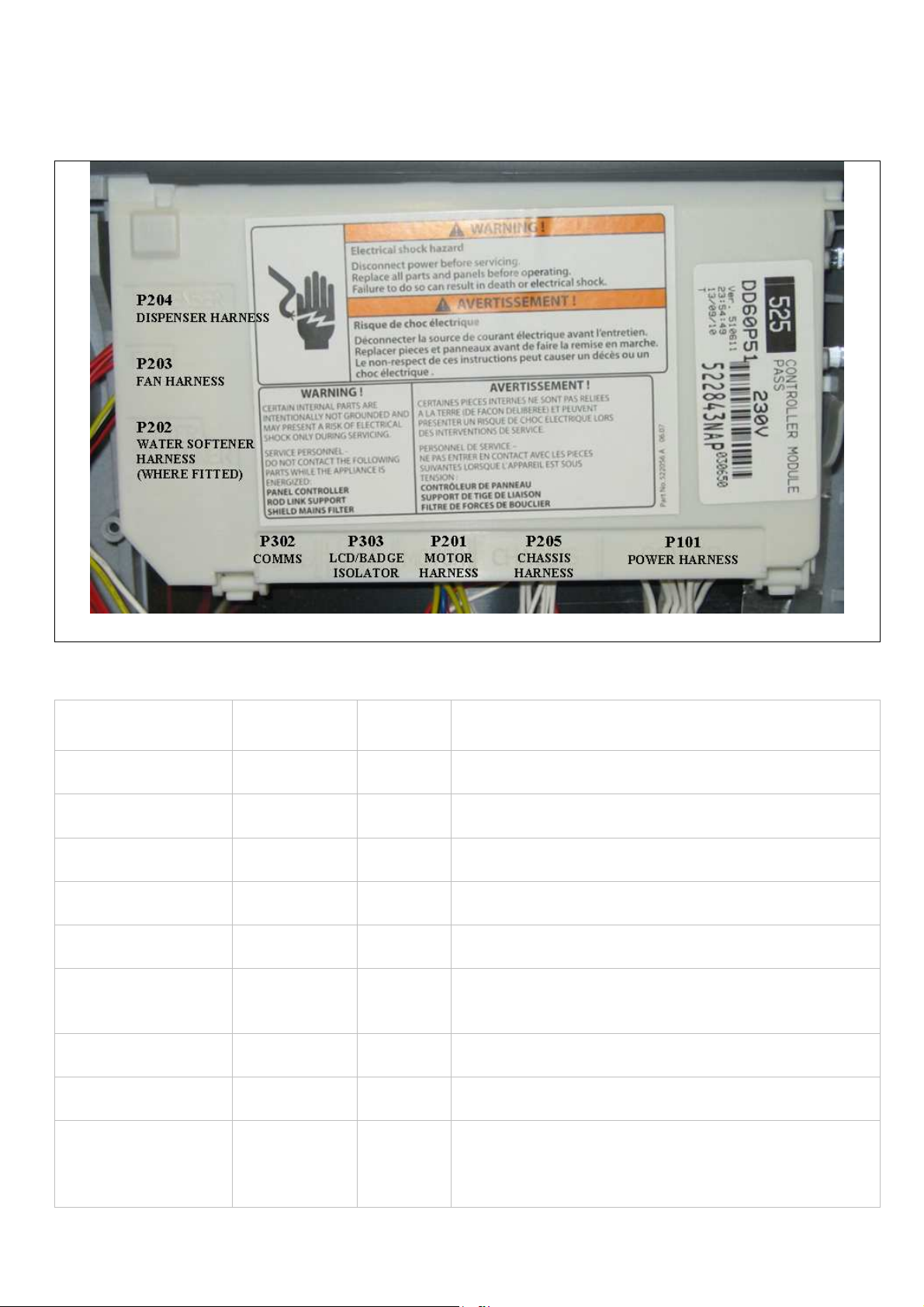
Device Connector
Fill valve P205 10 & 11 65 +/- 10 ohm
Lid motor P205 6 &7 Check if open or short circuit
Lid motor P205 8 & 9 Check if open or short circuit
Rinse aid pump P204 1 & 2 65 +/- 10 ohm
Detergent diverter P204 3 & 4 65 +/- 10 ohm
Fan P203 1 & 2 Check if open or short circuit
Water softener
bypass valve
Water softener
brine pump
Temperature
sensor
P202 1 & 2 65+/- 10 ohm
P202 3 & 4 65+/- 10 ohm
P101 1 & 2 12000 Ohms @ 200C (680F)
Pin
Pair
Description
Note: run in diagnostics and check fan torque
0
8300 Ohms @ 30
3000 Ohms @ 600C (1400F)
C (860F)
6
Page 7

Motor phases
P201
1 & 2 8.0 +/- 5 Ohms (per winding),
16 ohms phase to phase from the controller
connector
Dropper resistor
P101
4 & 5
NZ/AU/EU/UK
98 Ohms +/- 7 Ohms
US/CA
24 Ohms +/- 3 Ohms
Element
P101
and
Power Plug
6
to
Neutral
Pin
NZ/AU/EU/UK
DD605/DD60 - 50 ohm +/- 4 Ohms
DD90 - 38 ohm +/- 3 Ohms
US/CA
DD605/DD24 - 24 ohm +/- 3 Ohms
DD36 - 19 ohm +/- 2 Ohms
Note: DD90 & DD36 Heater track are in parallel, if one heater track fails, resistance will double.
(230V - 76 ohm : 120V - 38 ohm)
NOTE: Pins are counted right to left on connectors P101, P205, P201, P303, P302.
Connectors P202, 203, 204 – pin 1 is at the bottom of the connector.
7
Page 8

4.1
Component Checking Procedure
Number Procedure
1
Check Dropper Resistor:
This is checked at the power connector harness at the controller (P101)
Remove the harness from the controller, and using a multimeter check the resistance between pins 4 & 5
– be careful not to spread the pins with the meter probes.
The following resistances should apply:
NZ / AU / EU / UK
98 Ohms +/- 7 Ohms
US / CA
24 Ohms +/- 3 Ohms
If the dropper resistor is open circuit, then the heater plate will need to be replaced.
2
Check Fill Valve:
This is checked on the chassis harness (P205), between pins 10 & 11.
Remove the chassis harness from the controller, and using a multimeter check the resistance between
pins 10 & 11 – be careful not to spread the pins with the meter probes.
The following resistance should apply:
65 Ohms (+/- 10 Ohms)
If resistance is OK, continue checking other components.
If shorted replace the fill valve, but continue to check the other components.
8
Page 9

3
Check the lid actuators:
These are checked at the chassis harness (P205) between pins 6 & 7, 8 & 9.
Normal resistance range may vary, so only replace if open or short circuit.
4
Check the Detergent Dispenser and Rinse Aid Coils:
These can be checked on harness P204
Remove the dispenser harness from the controller, and using a multimeter check the resistance between
pins 1 & 2 for the rinse aid pump coil - take care not to spread the pins with the meter probes.
The following resistances should apply:
65 Ohms (+/- 10 Ohms)
9
Page 10

Check the resistance between pin 3 & 4 for the detergent diverter coil,
The following resistances should apply:
65 Ohms (+/- 10 Ohms)
If shorted replace the coil, but continue to check the other components.
Or, check the coils at the detergent dispenser, remove the connector and using a multimeter check the
resistance between the coil pins.
10
Page 11

5
Check the drying fan:
This can be checked on harness P203 on pins 3 & 4, it is not possible to check the resistance so you
should only replace if it is open or short circuit.
Or, run the fan in “HO” mode in diagnostics and check for air flow, if the fan exhibits poor performance (low
air flow) replace it.
6
Check the motor winding:
These can be checked on harness P201 at the controller.
To check remove the harness and measure resistance between pins 1&2, 2&3, 1&3 the following
resistances should apply:
8.0 +/- 5 Ohms (per winding),
16 ohms phase to phase from the controller connector.
11
Page 12

7
Check the Water Softener:
If fitted, check the water softener coils, these can be checked at harness P202
Remove the water softener harness from the controller, and using a multimeter check the resistance
between pins 1 & 2 for the softener bypass coil - take care not to spread the pins with the meter probes.
The following resistances should apply:
65 Ohms (+/- 10 Ohms)
Check the resistance between pin 3 & 4 for the brine pump,
The following resistances should apply:
65 Ohms (+/- 10 Ohms)
If shorted replace the coil, but continue to check the other components.
Or, the coils can be checked with a multimeter at the water softener itself.
12
Page 13

8
Check for Corrosion or Burning at the Controller Connections:
Check connections and check the secondary touch panel switches, to do this you will need to remove the
controller from the tub.
If the connections are burnt or corroded then the controller and harness will need replaced.
I
f there is signs of corrosion on the secondary touch panel, check for leaks on the tub flange, ensure this is
not leaking when getting hot.
Also check drying fan operation, and that the product vent is not blocked off causing a build up of
condensation.
13
Page 14

For integrated models check the length of the door panel, that this has not been extended and is covering
the fan duct, which will cause a build up of moisture behind the door panel.
14
Page 15

9
Check the Chassis board:
Check the chassis board (mains filter board) for any corroded/ burnt contacts or dry joints,
to do this remove the mains filer board from the housing.
15
Page 16

5 DIAGNOSTICS
5.1
DishDrawer™ diagnostics can only be entered in Power Off mode, i.e. when there is no display on the LCD, or the
badge LEDs are off.
Note: If the product has been powered off at the wall due to a fault code error, once power is turned back on, wait 20
seconds before trying to enter diagnostics, as the product will be doing a self check in this time, and will not allow
diagnostics to be entered.
Diagnostics is entered by holding the KEYLOCK and START/PAUSE buttons simultaneously for 5 seconds. Ensure
that KEYLOCK is pushed first
There are currently four levels of diagnostics. To move to the next level press POWER. To enter a level, press
START/PAUSE. Once a level has been entered, pressing POWER will exit diagnostics completely. If no level is
entered, then the display will cycle through the four levels and exit after the last. On entering diagnostics mode, the
first level is the display mode.
5.1.1
In this mode all LEDs and LCD segments (except keylock) are illuminated in the display.
.
DishDrawer Diagnostics
Display Mode – Level One
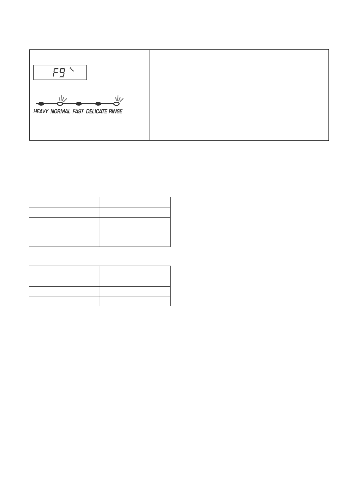
Pre Finished Integrated and Flat Door Models
The following LED’s will show on the secondary display
panel
The last two faults are displayed on the LCD for pre finished models.
For integrated or flat door models the secondary control panel LED will show a sequence of lights to show the fault
code.
The current fault code is displayed first followed by the previous fault code. E.g.
Pre Finished Integrated and Flat Door Models
F9 fault code
16
Page 17

5.1.2
This level tests all the hardware outputs and inputs. The LCD display shows ‘HO’
Hardware Output Test Mode – Level Two
Pre Finished
Integrated and Flat Door Models
Will show the following LED’s on secondary display
panel
Press POWER to skip hardware diagnostics and advance to the next level.
Press START/PAUSE to enter hardware diagnostics.
Once hardware diagnostics has been entered, letters in the LCD display indicate the current hardware output being
tested. For integrated models, the LEDs on the touch switch panel indicate the hardware output being tested, using
binary encoding, as shown in the table below.
Different combinations of outputs can be switched on or off together, but the controller will prevent components such as
the wash pump and the lid motors being turned on together.
Press START/PAUSE to advance to the next hardware output.
Press KEYLOCK to turn the currently displayed output on or off. If the bubbles symbol (green LED above start/pause
button on integrated models) is displayed, then that output has been switched on, and if it is not displayed then that
output is off.
For Phase 5.1 - the controller now monitors the power supply current when any (and only) one fill valve, detergent
diverter, water softener bypass valve, fan , rinse aid pump, water softener brine pump, wash or drain motor is turned on.
If the current is too high or too low on the component then after approx 5 seconds, the controller starts a long, low
tone repeated every second to advise the component is faulty, or disconnected. (except the water softener)
This test will not work if more than one hardware output has been turned on at the same time.
This test does not check lid motor current, as this varies too much to make useful measurements.
Press POWER to exit at any time (all outputs will be switched off on exit).
17
Page 18

LCD Norm Fast Deli Rinse Hardware Output
-------------------------------------------------------------------------------------------
bL Off Off Off On Backlight
Er Off Off On Off Element Relay (turns off after 5 seconds)
Ld Off Off On On Lid Motors (will run for 10 seconds)
dd Off On Off Off Detergent Diverter Valve
FU Off On Off On Fill Water Valve
P1 Off On On Off Motor Wash direction 2300-2850
P2 Off On On On Motor Drain direction 4200 rpm
rd On Off Off Off Rinse Aid Dispenser (
dispenses according to current user setting)
dF On Off Off On Drying fan
LE On Off On Off Rinse Aid and Salt Tank LEDs
C1 On Off On On Water Softener Diverter Valve
C2 On On Off Off Water Softener Brine Pump
C3 On On Off On Water Softener Brine Valve
°C On On On Off Displays current water temperature.
°E On On On On Displays controller rail voltage
rpm
(will not run if the tub is open)
(times out after 255 seconds.)
(C3 is used in the factory to empty the water softener before the product is packed.)
Tub Home Sensor Test: At any time during HO test mode the Keylock symbol on the LCD display (Keylock LED on
integrated badge) indicates the tub position. On = closed, off = open.
Press POWER to skip hardware diagnostics and exit mode.
5.1.3
Fast Test Cycle – Level Three
WARNING : Only run this cycle if connected to the water supply.
This level runs an 8-minute fast test cycle.
Flat door and Integrated will show the following LED’s on secondary display panel
.
Pre Finished Integrated and Flat Door Models
Will show the following LED’s on secondary
display panel
Press POWER to skip Fast Test Cycle and advance to the next level.
Press START/PAUSE to enter Fast Test cycle.
18
Page 19

Once the fast test cycle is selected, the DishDrawer™ goes into standby mode and 8 minutes will be showing on the
display. The test cycle is started by pressing START/PAUSE, and the following components are run during the 8 minute
cycle that follows: - Lid motors, fill valve, wash motor, element, drain motor, drying fan.
Press POWER to exit at any time.
The test sequence in fast cycle mode performs 33 tests. The number of any failed test is displayed on the touch switch
panel LEDs. The test sequence continues even if a test fails. If there are multiple failures the LEDs will change during the
test.
5.1.4
Not required for testing of F9 related faults.
Continuous Cycle Test Mode – Level Four
19
Page 20

6 WIRING DIAGRAM
20
Page 21

 Loading...