

Fisher & Paykel OD301V2-87980, OS301V1-88416, OS301MV1-87819, OS301V2-87931, OS301V2-87933 Installation Information
...Page 1
PAGE1OF8
P/N 545855E
DATEOFISSUE
11 / 2003
INSTALLATION INFORMATION
AEROTECH BUILT- IN OVENS
0S301 / 0D301 SERIES
IMPORTANT- SAVE FOR THE LOCAL ELECTRICAL INSPECTOR'S USE
Page 2
BEFORE YOU START
PAGE 2 OF 8
Correct installation is the responsibility of the customer.
Ensure that the installer is properly qualified to install this oven.
= Make surethat the oven is locatedaway fromany strong and/or hot drafts of air,
• Thecabinetopeningdimensionsspecifiedare the absoluteminimum. Thesedimensionsallow a clearance
of upto 1/4"(6mm).
° Theproductmust beelectrically grounded.See"Electrical Connection"for details,
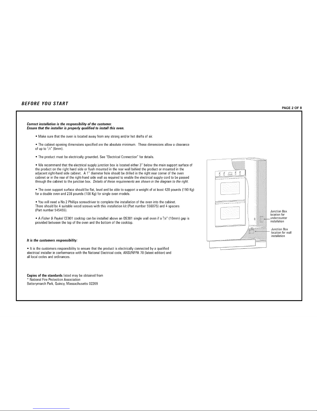
* We recommendthatthe electricalsupplyjunction boxis locatedeither3" belowthe main supportsurfaceof
the productonthe right handsideor flush mountedinthe rear wall behindthe productor mountedinthe
adjacentright-handsidecabinet. A 1" diameterholeshouldbe drilledinthe right rearcornerof the oven
cabinetorin the rearof the right-handside wall asrequiredto enablethe electricalsupply cordto be passed
throughthe cabinetto the junction box, Details of these requirementsareshownin the diagramto the right.
* Theoven supportsurface shouldbeflat, level and beableto supporta weight of at least 420 pounds(190 Kg)
for a doubleovenand 238 pounds(108 Kg)for singleovenmodels,
• Youwill needa No,2 Phillipsscrewdriverto completethe installationof the oveninto the cabinet.
Thereshouldbe4 suitablewood screws with this installationkit (Partnumber556075)and4 spacers
(Partnumber 545455),
* A Fisher8 PaykelCE901cooktopcan be installedabovean 0S301single wall ovenif a 3/8" (10mm)gap is
providedbetweenthe top of theoven andthe bottom of thecooktop.
It is the customersresponsibility:
• It is the customersresponsibilityto ensurethat the product iselectricallyconnectedby a qualified
electricalinstallerin conformancewith the NationalElectricalcode, ANSI/NFPA70 (latest edition)and
all local codes andordinances,
Junction Box
location for
undercounter
--installation
Junction Box
-- location for wall
installation
Copiesof the standardslisted may beobtainedfrom
* NationalFireProtectionAssociation
BatterymarchPark,Quincy,Massachusetts02269
Page 3
PRODUCT DIMENSIONS
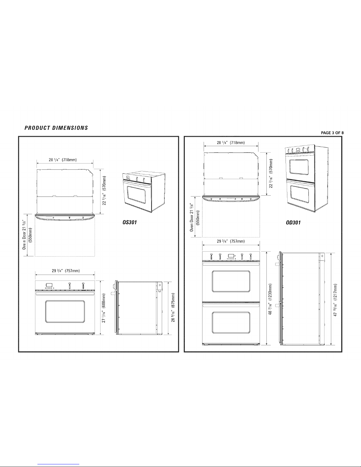
28 1/4" (718mm)
,\
51
29 3/4" (757mm)
......
E
O
LO
v
0S301
o
28 1/4" (718mm)
.\
_U --_ US
29 3/4" (757mm)
AE
E
O
LO
v
%
Z-
0D301
PAGE 3 OF 8
EA
E
p,..
F,
.C..
%
-.T.
p..
Page 4

PROUD DiMENSiONS RECESSED DiMENSiONS
TOP VIEW
Minimum Distance
Under Benchtop
for Single
2 3/4" (70ram}
etN/idt h
= o
__
-4r_
Minimum Distance
Under Benchtop
for Single ovens
2 314"{70ram)
._
, _etWidth
PAGE 4 OF 8
TOP VIEW
Page 5

PREPARING THE OVEN ELECTRICAL REQUIREMENTS
Unpacking the oven
Donot usedoorhandlesor any part of the controlpanel for liftingthe product.
Beforethe productislifted, the oven doorsand racks are to be removed.
-] ARNING: Extremecare isto betaken when liftingthe productas it
is veryheavy. Failureto do somay resultin injury.
1. Carefullylaythe producton its back. Removethe externalwrappingandthe
bottom polystyreneprotectorandpallet. Standthe productup and removeall
other polystyrenepackaging.
2. Removethe oven doors.This is doneby:
• Openthe oven doorfully.
• Lift the catcheson bothof the hingesover towards youontothe hooks
of the hingearm(see picture below).
• Raisethe doorslightly, holdingon eitherside nearthe handle,making
surethat the clips stay on the hooks.
WARNING: Do notlift the doorout bythe handleas this may cause
damageto the product.
• Liftthe doorout.
Door Hinge
Door
--_ ARNING: Do notdisengagethehingehookswhen thedoorhas
been removedas theyare differcult to re-engage.
3. Removethe wire shelvesand oventrays by slidingthem out. Useboth hands
to removeeachitem. Removethe cardboardpackagingfrom the ovencavity.
PAGE 5 OF 8
Theelectricalvoltage andfrequencythat is correct for this ovenis stated onthe
serialnumberplate locatedinsidethe top vent. It is the customerresponsibilityto
ensurethat this ovenis connectedto the correct electrical supply.
WARNING : The oven must beconnectedto a permanentand
groundedsupply.
Maximum currentdraw: Maximum Load:
Double: 3&2 amps 9.2 kW
Single: 21 amps 5.1 kW
CONNECTOVENWITH COPPERWIRE ONLY
• Theflexiblearmouredcableshould beconnecteddirectlyto the junction box.
• Do not cut the conduit,
• A U.L.listed conduit connectormust beprovidedat thejunction box.
• Do not groundto a gaspipe.
• Do not havea fuse in the groundingor neutral circuit.
• Fuseboth sidesof the line.
• A time delayfuse or circuit breakeris recommended. If using a time delay
fuse,thenfuse both sides of the line.
• Flexiblearmouredcablefrom the applianceshouldbe connecteddirectly to
the junction box.
• Connectdirectlyto the fused disconnect(or circuit breakerbox)throughflexible,
armoredor non-metallicsheathed,coppercable (with groundingwire).
• If codespermit anda separategroundingwire is used,it is recommended
that a qualifiedelectriciandeterminethat the groundingpathand wire gauge
is in accordancewith localcodes.
• Do not usean extensioncord with this appliance.
Page 6

ELECTRICAL CONNECTION
PAGE 6 OF 8
0,9
This oven is manufactured with white (neutral) power supply wire and a cabinet-connected green grounding wire taped together.
Feedthe oven cablethrough the openingin the cabinet.Makethe electrical connectionfollowing thesteps appropriatefor your installation,
1. Disconnectthe power supply.
------_WARNING : Failureto disconnectthe power supplymayresult in deathor injury.
2. Removethejunction boxcover.
3. Connectthe ovencableto the junction box throughthe U.L-listed conduit connector,
4. Connectthe two blackwires togetherwith twist-on connectors,
5. Connectthe two redwires togetherwith twist-on connectors.
6. Connectelectricalconnectionaccordingto localcodesand ordinances,
If localcodesPERMITconnectingcabinet-groundingconductorto neutralwhite wire in
the junctionbox:
7. Connectthe factory-crimpedgreenandwhite ovencablewires to the
neutral(white) wire inthe junction box,
8. Replacethe junction boxcover,
If localcodesDO NOT PERMITconnectingcabinet-groundingconductorto neutral
(white) wire in junctionbox:
7. Separatethe factory-crimpedgreenandwhite ovencablewires,
8. Connectwhite ovencablewire to neutral(white) wire in junction box.
9. Connectthe greengroundingoven cable wire to a groundedwire in the junction box,
10. Replacethejunction boxcover.
Cable from
JrlnuCt_i n box po_ _pply wires
grounding oven wires
- factory crimped _ " " - ! nector
junction box
red wires
Cable from
po_ upply
white wires
0,9 If connectingto a four-wire electrical system:
7. Separategreenand white oven cablewires.
8. Connectwhite ovencablewire to neutral(white) wire in junction box.
9. Connectthe greengroundingoven cable wire to the (green) groundingwire inthe junction box.
Donot connectgreen groundingwire to neutral(white) wire in junction box,
18. Replacethejunction boxcover,
green grounding
wires- oven wire
factory crimped
U,L. - listed
conduit connector
Page 7

A TTA CHMEN T
1. Feed the electrical supplycable into 1" holecut out of the rear
of the oven cabinet.
WARNING : Extremecare is to betakenwhen liftingthe productas it
isvery heavy. Failureto do somay resultin injury.
Slidethe productintothe oven cabinet,pushingthe productbetweenthe two oven
cavitiesor by the edgesof the ovencavity.
Make surethat the electrical supplycablecan drop straightdown usingthe
recesson the rearof the oven intothe cable entryhole inthe rear of the oven
cavity. If the productdoesnotsit flush with the frontof the oven cabinet,
makecertainthatthe electrical supplycablehas not jammed behindthe
product. Ensurethebottomventis notblockedoff or damaged.
,
Securelyfastenthe oven to the cabinetusingthe screws provided. Insertthe
screws throughthe holes in the sideextrusionsandthroughthe spacersplaced
betweenthe sideextrusion andthe kitchenjoinery(see diagramopposite).
Do not over tightenscrews.
,
Replacethe oventrays and wire shelves. Theshelveshave a
front and back. Insert them into the ovenin the correct way to
ensurethat the 'stop-lock' featureof the shelf works correctly
(seediagramapposite).
4,
Refitthe oven doors. This is done by:
Placeboth upper hingearms inthe top slots andboth lower
hingearmsin the lower slots.
Pushthe hinges asfar as they will go until the slot in the lower
armlocatesin the hingesupport.
Lowerthe doorgently. Pushthe catchesaway from you off the
hooks. Makesurethat they disengageproperly.
Raisethe doorslightlyand ensurethe catchesare releasedfrom
the hooks. The doorcan now be closed.
--_ WARNING : Donot standor siton the doors.
\ J
/
PAGE 7 OF 8
Page 8

CHECKLIST TROUBLE SHOOTING
PAGE 8 OF 8
1. Makesure productis levelandsecurelyfitted to the cabinetry and
both ovendoorsopenandclosefreely.
2. Make sure allthe internalpackaginghasbeenremovedfrom the oven cavity.
3. Make sure alloven ventsand openingsareclear andare free of anyobstruction.
F_ WARNING :
Failureto do so may resultin a fire or poorproductperformance.
4. Turnthe power to the ovenon. The clockshould light up and blink 12:00pm.
5. Set the clockto the currenttime.
6. Turnthe ovenfunctionswitch to 'Bake'and the oventemp switch to 350' F. Air
shouldblow out of the vent at the bottom of the oven. Insidethe ovencavity allthree
ovenlights shouldcomeon. After 5 minutesopenthe oven doorandthe air inside
shouldfeel warm. Thetop elementshouldbe glowing redandthe bottom surfaceof
the ovencavity shouldfeel warm to lightly touch.
[_ WARNING :
Donottouch thetop elementas this may resultin injury.
7. Turnboththe ovenfunction switch and oventemp switch backto off andrepeat
for the other oven if product isa double.
IF THEOVENDOESNOTOPERATE:
* Checkthatthe circuit breakerhas not trippedor the fuse blown.
• Makesurethat the electrical connectionshavebeencorrectly made.
• Makesurethat power is beingsuppliedto the oven.
, Makesure the voltageis correct across all phases.
IF YOUNEEDASSISTANCE:
• If a fault occurs consultthe ProblemSolverSectionof your UserGuidebook.
• CallyourlocalCustomerCarerepresentativeon 1-8889FNPUSA(1-8889 367 872).
• Pleasehavethe model andserialnumberof your productreadyfor the
CustomerCarerepresentative.
 Loading...