

Fisher Mounting DVC6200/DVC2000 on an IEC60534-6-1 (Old NAMUR) Sliding Stem Actuator Installation Instructions
Page 1

DVC6200 or DVC2000 Digital Valve
Mounting Instructions
Controller on an IEC60534-6-1 (Old
D103458X012
April 2010
Use these instructions to mount a FisherR FIELDVUEt
DVC6200 or DVC2000 digital valve controller on an
IEC60534-6-1 (old NAMUR) sliding stem actuator.
WARNING
Avoid personal injury or property
damage from sudden release of process
pressure or bursting of parts. Before
performing any maintenance operations:
D Always wear protective clothing,
gloves, and eyewear.
D Do not remove the actuator from the
valve while the valve is still pressurized.
D Disconnect any operating lines
providing air pressure, electric power, or
a control signal to the actuator. Be sure
the actuator cannot suddenly open or
close the control valve.
D Use bypass valves or completely
shut off the process to isolate the control
valve from process pressure. Relieve
process pressure from both sides of the
control valve.
D Vent the pneumatic actuator loading
pressure and relieve any actuator spring
precompression.
D Use lock-out procedures to be sure
that the above measures stay in effect
while you work on the equipment.
D Check with your process or safety
engineer for any additional measures
that must be taken to protect against
process media.
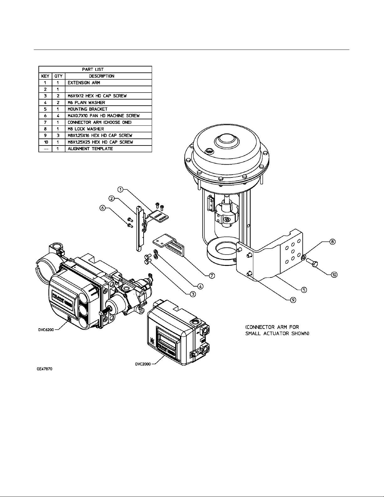
Refer to figures 3, 4 and 5 for mounting parts
identification. Refer to the DVC6200 or DVC2000
digital valve controller instruction manual for digital
controller parts identification. Refer to the appropriate
actuator instruction manual for actuator installation,
operation, maintenance, and parts identification.
1. Isolate the control valve from the process line
pressure and release pressure from both sides of the
valve body. Shut off all pressure lines to the actuator,
releasing all pressure from the actuator. Use lock-out
procedures to be sure that the above measures stay in
effect while you work on the equipment.
2. Two connector arms are provided (see figure 1),
one suitable for use with small actuators and one for
use with large actuators; select the appropriate one for
NAMUR) Sliding Stem Actuator
the actuator being used (figures 3, 4 and 5 show the
size for small actuators).
3. Ensure the actuator/valve stem connector mounting
face is visually square with the actuator yoke legs.
Attach the connector arm (key 7) to the stem connector
using the two hex head cap screws (key 3) and plain
washers (key 4), but do not tighten (see figures 3, 4
and 5).
4. Attach the mounting bracket (key 5) to the yoke leg
using the appropriate hardware for the actuator
mounting style.
a. Figure 3 shows pillar style mounting. For rough
alignment of pillar style actuators, center the
primary hole in the bracket with the approximate
mid-travel position of the stem connector. Visually
square up the bracket relative to the actuator yoke
legs, then tighten the fasteners.
b. Figure 4 shows rib style mounting. For rib style
mounting, select the primary hole for most
actuators. The alternate hole may be required for
small actuators.
c. Figure 5 shows plane surface style mounting.
5. Attach the magnet assembly (key 2) to the
extension arm (key 1) with two pan head machine
screws (key 6) but do not tighten.
6. Attach the extension arm and the magnet assembly
to the connector arm using two pan head machine
screws, (key 6) but do not tighten. The next step will
ensure that the connector arm selected is suitable.
7. Attach the black plastic alignment template to the
mounting bracket assembly by inserting the two
protruding posts into the two mounting holes in the
bracket and simultaneously position the magnet
assembly so that it can slide into the channel in the
alignment bracket. The magnet assembly should be
fully in the alignment template channel so that the
extension arm is contacting the back of the alignment
template but not bending it. Tighten the hex head cap
screws (key 3) at the stem connector and pan head
machine screws (key 6) attaching the extension arm to
the connector arm but do not yet tighten the pan head
machine screws attaching the magnet assembly.
www.Fisher.com
Page 2

DVC6200 or DVC2000 Digital Valve
Controller on an IEC60534-6-1 (Old
NAMUR) Sliding Stem Actuator
8. For an air-to-extend actuator, slide the magnet
assembly (key 2) so that the bottom marking aligns
with the sensor index mark on the alignment template
(see figure 2). The top marking of the magnet assembly
is used for air-to-retract. The mounting bracket may
require vertical repositioning to get the magnet
assembly in the correct location. When the magnet
assembly is properly positioned, remove the alignment
template and tighten the two pan head machine screws
(key 6).
9. Attach the digital valve controller to the mounting
bracket assembly and tighten the three hex head cap
screws (key 9).
10. Check the position of the magnet assembly (key 2)
in the channel of the digital valve controller housing
and ensure that it is visually centered between the
channel walls and has adequate clearance with the
backside of the channel (approximately 3 mm).
11. Connect and calibrate the digital valve controller as
described in the instruction manual or quick start guide.
For additional information concerning the mounting,
setup, calibration and maintenance of the DVC6200 or
DVC2000 digital valve controller, refer to the
appropriate instruction manual or quick start guide.
(A)
Mounting Instructions
D103458X012
April 2010
(B)
A) CONNECTOR ARM FOR LARGER SIZE ACTUATOR
B) CONNECTOR ARM FOR SMALLER SIZE ACTUATOR
Figure 1. Connector Arm
Note
Neither Emerson, Emerson Process
Management, , nor any of their affiliated
entities assumes responsibility for the
selection, use and maintenance of any
product. Responsibility for the selection,
use and maintenance of any product
remains with the purchaser and end
user.
FIGURE SHOWS MAGNET
ASSEMBLY MARKING ALIGNED
WITH SENSOR INDEX MARK
FOR AIR-TO-EXTEND ACTUATOR
ASSEMBLY MARKING
Figure 2. Alignment Template
2
Page 3

DVC6200 or DVC2000 Digital Valve
Mounting Instructions
D103458X012
April 2010
MAGNET ASSEMBLY
Controller on an IEC60534-6-1 (Old
NAMUR) Sliding Stem Actuator
Figure 3. Mounting Parts Identification for Pillar Style Mounting
3
Page 4
DVC6200 or DVC2000 Digital Valve
Controller on an IEC60534-6-1 (Old
NAMUR) Sliding Stem Actuator
MAGNET ASSEMBLY
Mounting Instructions
D103458X012
April 2010
Figure 4. Mounting Parts Identification for Rib Style Mounting
4
Page 5

DVC6200 or DVC2000 Digital Valve
Mounting Instructions
D103458X012
April 2010
MAGNET ASSEMBLY
Controller on an IEC60534-6-1 (Old
NAMUR) Sliding Stem Actuator
Figure 5. Mounting Parts Identification for Plane Surface Style Mounting
Fisher and FIELDVUE are marks owned by one of the companies in the Emerson Process Management business division of Emerson Electric Co.
Emerson Process Management, Emerson, and the Emerson logo are trademarks and service marks of Emerson Electric Co. All other marks are the
property of their respective owners.
The contents of this publication are presented for informational purposes only, and while every effort has been made to ensure their accuracy, they
are not to be construed as warranties or guarantees, express or implied, regarding the products or services described herein or their use or
applicability. All sales are governed by our terms and conditions, which are available upon request. We reserve the right to modify or improve the
designs or specifications of such products at any time without notice. Neither Emerson, Emerson Process Management, nor any of their affiliated
entities assumes responsibility for the selection, use or maintenance of any product. Responsibility for proper selection, use, and maintenance of
any product remains solely with the purchaser and end user.
Emerson Process Management
Marshalltown, Iowa 50158 USA
Sorocaba, 18087 Brazil
Chatham, Kent ME4 4QZ UK
Dubai, United Arab Emirates
Singapore 128461 Singapore
www.Fisher.com
EFisher Controls International LLC 2010; All Rights Reserved
5
 Loading...