

Fisher Manual: Mounting DVC6200/DVC2000 on 1052 Size 20 (End Mount) | Fisher Manuals & Guides

DVC6200 or DVC2000
Mounting Instructions
D103451X012
June 2010
Use these instructions to mount a Fisherr FIELDVUEt
DVC6200 or DVC2000 digital valve controller on 1052
size 20 actuators.
1052 Size 20 Actuator (End Mount)
WARNING
Avoid personal injury or property
damage from sudden release of process
pressure or bursting of parts. Before
performing any maintenance operations:
D Always wear protective clothing
and eyewear.
D Do not remove the actuator from
the valve while the valve is still
pressurized.
D Disconnect any operating lines
providing air pressure, electric power, or
a control signal to the actuator. Be sure
the actuator cannot suddenly open or
close the control valve.
D Use bypass valves or completely
shut off the process to isolate the
control valve from process pressure.
Relieve process pressure from both
sides of the control valve.
D Vent the pneumatic actuator
loading pressure and relieve any
actuator spring precompression.
D Use lock-out procedures to be sure
that the above measures stay in effect
while you work on the equipment.
D Check with your process or safety
engineer for any additional measures
that must be taken to protect against
process media.
Refer to figure 2 and the parts list for mounting parts
identification. Refer to the appropriate instrument
instruction manual listed below for instrument parts
identification. Refer to the appropriate actuator
instruction manual for actuator installation, operation,
maintenance, and parts identification.
1. Isolate the control valve from the process line
pressure and release pressure from both sides of the
valve body. Shut off all pressure lines to the actuator,
releasing all pressure from the actuator. Use lock-out
procedures to be sure that the above measures stay in
effect while you work on the equipment.
Digital Valve Controller on
2. The instrument can be mounted in four different
orientations on the 1052. Figure 1 shows the
instrument mounted upright relative to the actuator
spring barrel.
WARNING
To avoid personal injury due to the
sudden, uncontrolled movement of
parts, do not remove the actuator hub or
hub fasteners when the valve shaft has
actuator spring force applied to it.
3. Mounting the instrument on the 1052, size 20
actuator requires removal of the actuator hub to
replace the actuator travel indicator scale with a
retaining plate (key 14).
4. Remove the travel indicator and its cap screws from
the actuator hub, if present. Unscrew the machine
screws to remove the actuator hub and travel indicator
scale subassembly.
5. Once the actuator hub and travel indicator scale
subassembly has been removed from the actuator,
remove the retaining ring and the travel indicator scale
from the hub. Assemble the retaining plate (key 14) on
the hub and reinstall the retaining ring.
6. Reassemble the hub and retaining plate
subassembly to the actuator and attach the coupler
(key 1) to the actuator shaft using the pan head screws
(key 2) and tighten. For best visibility, the coupler
should be oriented on the shaft so that the pointer will
rotate in the quadrant above or below the instrument as
shown in figure 2.
7. Attach the mounting bracket (key 3) with the four
cap screws (key 13) and tighten. Ensure the hub is
positioned on the valve shaft so that the travel indicator
screw holes are aligned with the offset portion (where
the rod end bearing connects) of the lever.
Reassemble the actuator and readjust the actuator
spring.
8. Place the pointer (key 4) before attaching the
magnet assembly (key 5) to the coupler using pan
head screws (key 6) and tighten.
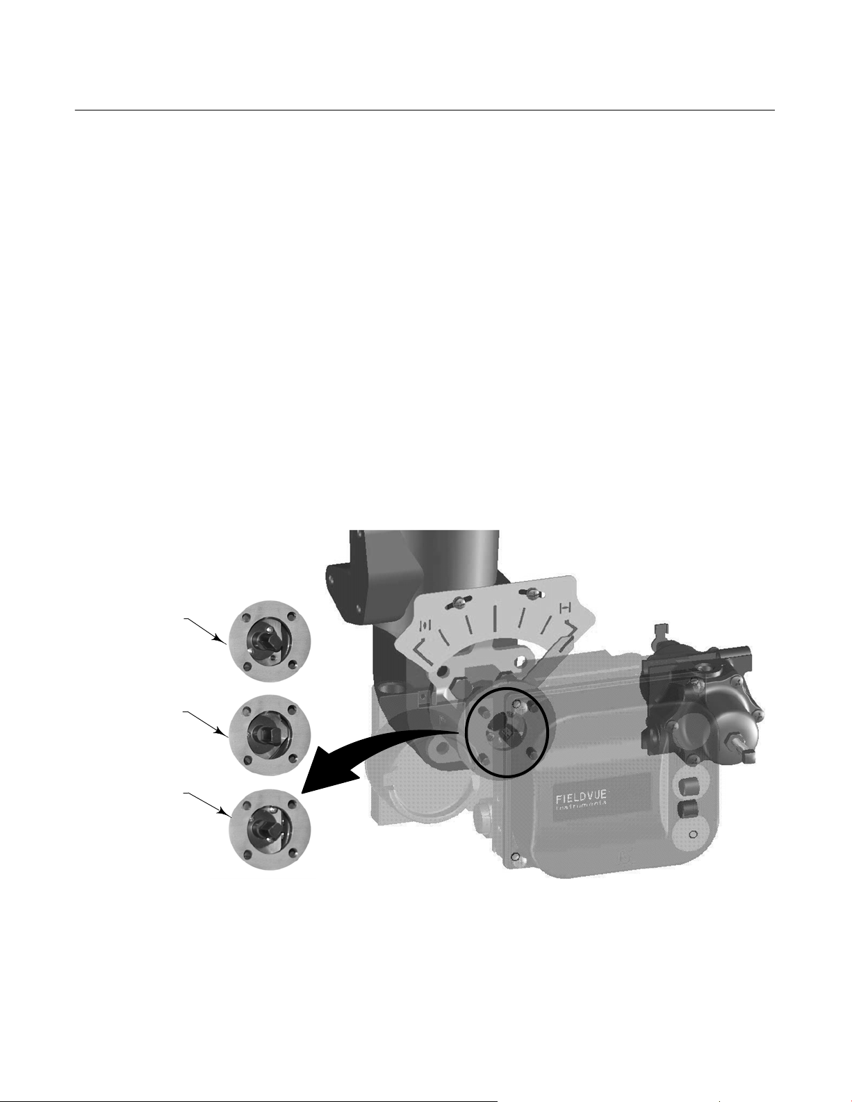
The magnet assembly must be oriented per figure 1,
so that the flats are approximately as shown relative
to the channel in the instrument housing when at the
mid−travel position.
www.Fisher.com
DVC6200 or DVC2000
Digital Valve Controller on
1052 Size 20 Actuator (End Mount)
9. Attach the mounting plate (key 7) to the mounting
bracket using pan head screws (key 11) and two
washers (key 9) and tighten.
10. Attach the travel indicator scale (key 8) to the
mounting plate using the remaining two plain washers
(key 9) and pan head machine screws (key 10). Refer
to figure 2.
11. Attach the digital valve controller to the mounting
bracket using hex head cap screws (key 12) but do not
tighten the screws. Visually adjust the digital valve
controller so that the magnet assembly is centered in
the housing channel and then tighten the fasteners.
Recheck the magnet assembly position again after
tightening.
12. Connect and calibrate the instrument as described
in the appropriate instruction manual.
Mounting Instructions
D103451X012
June 2010
For additional information concerning the mounting,
setup, calibration, and maintenance of the DVC6200
or the DVC2000 digital valve controller refer to the
appropriate instruction manual.
Note
Neither Emerson, Emerson Process
Management, nor any of their affiliated
entities assumes responsibility for the
selection, use, or maintenance of any
product. Responsibility for the selection,
use, and maintenance of any product
remains with the purchaser and end
user.
ORIENTATION AT
ONE TRAVEL
EXTREME
ORIENTATION AT
MID-TRAVEL (FLATS
PARALLEL TO
INSTRUMENT
HOUSING CHANNEL)
ORIENTATION AT
THE OTHER TRAVEL
EXTREME
W9074
Figure 1. Magnet Assembly Orientation
2
 Loading...