


Form Number D5142
Part Number D301726X012
September 2012
ControlWave Utilities Manual
Remote Automation Solutions

IMPORTANT! READ INSTRUCTIONS BEFORE STARTING!
Be sure that these instructions are carefully read and understood before any operation is attempted. Improper
use of this device in some applications may result in damage or injury. The user is urged to keep this book filed
in a convenient location for future reference.
These instructions may not cover all details or variations in equipment or cover every possible situation to be
met in connection with installation, operation or maintenance. Should problems arise that are not covered
sufficiently in the text, the purchaser is advised to contact Emerson Process Management, Remote Automation
Solutions for further information.
EQUIPMENT APPLICATION WARNING
The customer should note that a failure of this instrument or system, for whatever reason, may leave an
operating process without protection. Depending upon the application, this could result in possible damage to
property or injury to persons. It is suggested that the purchaser review the need for additional backup
equipment or provide alternate means of protection such as alarm devices, output limiting, fail-safe valves,
relief valves, emergency shutoffs, emergency switches, etc. If additional information is required, the purchaser
is advised to contact Remote Automation Solutions.
RETURNED EQUIPMENT WARNING
When returning any equipment to Remote Automation Solutions for repairs or evaluation, please note the
following: The party sending such materials is responsible to ensure that the materials retu rned to Remote
Automation Solutions are clean to safe levels, as such levels are defined and/or determined by applicable
federal, state and/or local law regulations or codes. Such party agrees to indemnify Remote Automation
Solutions and save Remote Automation Solutions harmless from any liability or damage which Remote
Automation Solutions may incur or suffer due to such party's failure to so act.
ELECTRICAL GROUNDING
Metal enclosures and exposed metal parts of electrical instruments must be grounded in accordance with
OSHA rules and regulations pertaining to "Design Safety Standards for Electrical Systems," 29 CFR, Part 1910,
Subpart S, dated: April 16, 1981 (OSHA rulings are in agreement with the National Electrical Code).
The grounding requirement is also applicable to mechanical or pneumatic instruments that include electrically
operated devices such as lights, switches, relays, alarms, or chart drives.
EQUIPMENT DAMAGE FROM ELECTROSTATIC DISCHARGE VOLTAGE
This product contains sensitive electronic component s that can b e damaged by exposure to an electrostatic
discharge (ESD) voltage. Depending on the magnitude and duration of the ESD, this can result in erratic
operation or complete failure of the equipment. Read supplemental document S14006 for proper care and
handling of ESD-sensitive components.
Remote Automation Solutions

ControlWave Utilities Manual (D5142)
Contents
Chapter 1 – Introduction 1-1
1.1 What are the ControlWave Utilities? ......................................................................................... 1-1
Chapter 2 – Using ControlView 2-1
2.1 Files are downloaded to the ControlWave using ControlWave Downloader ............................ 2-1
2.2 Starting ControlView ................................................................................................................. 2-3
2.3 Establishing a Connection with the ControlWave and Uploading File(s) .................................. 2-4
Chapter 3 – Using DataView 3-1
3.1 Starting DataView ..................................................................................................................... 3-2
3.2 Using the Tool Bar within DataView .......................................................................................... 3-2
3.3 Signing on to a Node ................................................................................................................. 3-3
3.4 Printing the Entries in the Current DataView Window............................................................... 3-3
3.5 Exporting Data Entries to the Windows Clipboard ................................................................. 3-3
3.6 Conducting a Signal Search ...................................................................................................... 3-4
3.6.1 Starting the Signal Search ............................................................................................ 3-4
3.6.2 Saving Search Criteria .................................................................................................. 3-9
3.6.3 Retrieving Search Criteria ............................................................................................. 3-9
3.6.4 Altering Search Criteria ................................................................................................. 3-9
3.7 Viewing Entries in a Signal Window ........................................................................................ 3-10
3.7.1 Changing Signal Values in the Signal Window ........................................................... 3-11
3.7.2 Changing Signal Inhibit/Enable Bits in the Signal Window ......................................... 3-12
3.7.3 Changing the Floating Point Format of Data in the Signal Window ............................ 3-12
3.8 Displaying a Remote Signal List ............................................................................................. 3-13
3.8.1 Selecting a Different Remote Signal List .................................................................... 3-13
3.8.2 Changing Remote List Signal Values, Altering Inhibit/Enable Bits ............................. 3-13
3.9 Creating and Using DataView Lists ........................................................................................ 3-14
3.9.1 Creating a DataView List ............................................................................................. 3-14
3.9.2 Collecting Live Data into the DataView List ................................................................ 3-15
3.9.3 Saving the DataView List ............................................................................................ 3-15
3.9.4 Viewing a Previously Saved DataView List ................................................................. 3-15
3.10 Creating and Using Recipes ................................................................................................... 3-15
3.10.1 Creating a Recipe ....................................................................................................... 3-15
3.10.2 Saving the Recipe ....................................................................................................... 3-16
3.10.3 To View/Modify an Existing Recipe File ...................................................................... 3-17
3.10.4 To Update Signals in the Controller with the Recipe Values ...................................... 3-17
3.10.5 To Read the Current Signal Values From the Controller Into the Recipe Window ..... 3-17
3.10.6 To Cancel Unsaved Modifications to the Recipe Values ............................................ 3-17
3.10.7 Changing the Floating Point Format of Data in the Recipe Window........................... 3-17
3.11 Viewing Data for a Single Signal ............................................................................................. 3-18
3.11.1 Acknowledging an Alarm ............................................................................................. 3-19
3.12 Viewing Data Arrays ................................................................................................................ 3-19
3.12.1 Changing Values in the Data Array ............................................................................. 3-20
3.12.2 Toggling the Time/Value Format ................................................................................. 3-21
3.12.3 Keeping Column 1 Visible While Scrolling Through the Array .................................... 3-21
3.12.4 Calling Up a Different Data Array ................................................................................ 3-21
3.12.5 Changing the Floating Point Format ........................................................................... 3-21
3.13 Viewing Audit Trail Records .................................................................................................... 3-21
3.14 Viewing Archive Data Files ..................................................................................................... 3-24
Issued Sep-2012 Contents iii

ControlWave Utilities Manual (D5142)
3.14.1 Keeping Column 1 Visible While Scrolling Through the Archive File ......................... 3-25
3.14.2 Calling Up a Different Archive File .............................................................................. 3-25
3.14.3 Changing the Floating Point Format ........................................................................... 3-25
3.14.4 Restrictions on Archive File Size ................................................................................ 3-25
Chapter 4 – Using the Downloader 4-1
4.1 Downloading to a ControlWave-series Node: ........................................................................... 4-1
4.1.1 Before You Begin .......................................................................................................... 4-1
4.1.2 Starting the ControlWave Downloader.......................................................................... 4-4
4.1.3 Using the ControlWave Downloader ............................................................................. 4-4
Chapter 5 – Using the Flash Configuration utility 5-1
5.1 Starting the Flash Configuration Utility ...................................................................................... 5-1
5.2 Flash Configuration Utility Buttons ............................................................................................ 5-4
5.3 Forcing a Reboot of the ControlWave ....................................................................................... 5-6
5.4 Flash Configuration Utility Tabs ................................................................................................ 5-7
5.5 Soft Switches ............................................................................................................................ 5-8
5.6 Ports .......................................................................................................................................... 5-9
5.6.1 IP Network Security Protocols (CHAP and PAP) Used on PPP Links ....................... 5-14
5.6.2 Challenge Handshaking Authentication Protocol (CHAP) .......................................... 5-15
5.6.3 Password Authentication Protocol (PAP) ................................................................... 5-18
5.7 IP Parameters ......................................................................................................................... 5-25
5.8 Application Parameters ........................................................................................................... 5-30
5.9 Archive .................................................................................................................................... 5-32
5.10 Audit ........................................................................................................................................ 5-37
5.11 IP Routes ................................................................................................................................ 5-40
5.12 Security ................................................................................................................................... 5-42
Chapter 6 – Using the Communication Statistics Tool 6-1
6.1 Accessing the Remote Communication Statistics Tool ............................................................ 6-2
6.2 Signing On to a Node ................................................................................................................ 6-3
6.3 Crash Block Statistics Window ................................................................................................. 6-3
6.4 Port Summary Statistics Window .............................................................................................. 6-5
Port Detail Statistics Window.................................................................................................... 6-6
Master/Expanded Addressing Master Port Statistics ............................................................... 6-6
Slave, Pseudo-Slave, Pseudo-Slave with Alarms, Serial CFE or VSAT Slave Port Statistics 6-7
Custom Port Statistics .............................................................................................................. 6-8
Internet Protocol (IP) Port Statistics ......................................................................................... 6-8
6.5 Version Information Window ..................................................................................................... 6-9
6.6 Node Routing Table Window .................................................................................................. 6-11
6.7 Internet Protocol (IP) Statistics Window .................................................................................. 6-12
IP Statistics Decription ............................................................................................................ 6-13
ICMP Statistics Description .................................................................................................... 6-14
UDP Statistics Description ...................................................................................................... 6-15
IBP Statistics Description ....................................................................................................... 6-16
6.8 Printing the Entries in the Current Window ............................................................................. 6-17
6.9 Exporting Data Entries to the Windows™ Clipboard ................................................................ 6-17
Chapter 7 – Using the System Firmware Downloader 7-1
7.1 What is System Firmware? ....................................................................................................... 7-1
7.2 Requirements for Using the System Firmware Downloader ..................................................... 7-2
7.3 Starting the System Firmware Downloader .............................................................................. 7-3
7.4 Downloading System Firmware to a Single Controller ............................................................. 7-4
7.5 Setting Application Parameters for the System Firmware Downloader .................................... 7-5
iv Contents Issued Sep-2012

ControlWave Utilities Manual (D5142)
Security Tab .............................................................................................................................. 7-5
Batch Mode Tab ....................................................................................................................... 7-6
7.6 Using PROM Reporter to see which Firmware is Loaded in an RTU ....................................... 7-6
Issued Sep-2012 Contents v

This page is intentionally left blank

ControlWave Utilities Manual (D5142)
Chapter 1 – Introduction
This manual provides instructions for using ControlWave utilities
software.
In This Chapter
1.1 What are the ControlWave Utilities? ................................................ 1-1
1.1 What are the ControlWave Utilities?
OpenEnterprise™ Field Tools includes a set of utility programs used
with ControlWave controllers. Most are launched from within
TechView. These utilities include:
ControlView File Viewer – This utility retrieves certain file types
from the ControlWave’s flash memory, and launches associated
applications so you can view them on the PC, such as HTML files.
ControlWave Downloader – This utility takes the ControlWave
project you create with ControlWave Designer and downloads it into
the ControlWave controller.
DataView – This utility collects various kinds of data from the
ControlWave for you to view on screen (variable values, lists,
archives, arrays).
Flash Configuration utility – This utility lets you update
configuration parameters in the ControlWave’s flash memory for
things like communication ports, IP addresses, memory, and so on.
Remote Communication Statistics utility – This utility lets you view
statistics regarding the “health” of ControlWave communications.
System Firmware Downloader – This utility lets you perform an
upgrade to the system firmware in the ControlWave.
Besides these utilities, there are other software programs for
ControlWave devices accessible in Field Tools; for information on
these, consult the sources listed in Table 1-1.
Table 1-1 Finding information about other ControlWave software
included within Field Tools
Software Description See these sources of information
Used to create control
strategy
ControlWave Designer
Debug_Info Tools
Issued Sep-2012 Introduction 1-1
(ControlWave project)
that executes inside
the ControlWave
controller.
Provides certain
debug information;
Getting Started with ControlWave
Designer (D5085)
ControlWave Designer
Programmer’s Handbook (D5125)
Online help in ControlWave Designer
ControlWave Designer
Programmer’s Handbook (D5125) –
ControlWave Utilities Manual (D5142)
Software Description See these sources of information
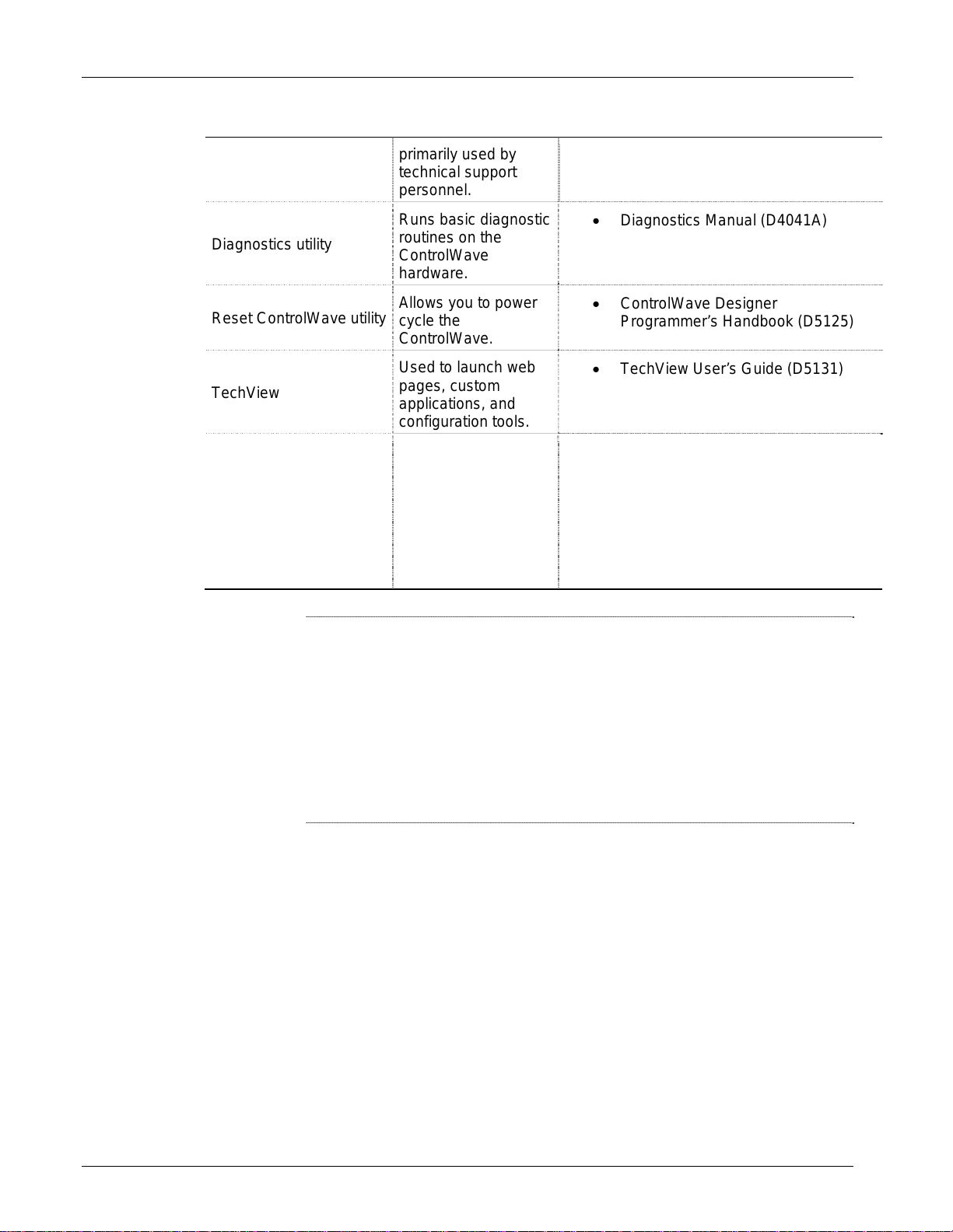
Diagnostics utility
Reset ControlWave utility
TechView
Web_BSI
primarily used by
technical support
personnel.
Runs basic diagnostic
routines on the
ControlWave
hardware.
Allows you to power
cycle the
ControlWave.
Used to launch web
pages, custom
applications, and
configuration tools.
A set of HTML pages
and web controls
specifically geared
towards
communication with
and data collection
from ControlWave
devices.
Appendix B
Diagnostics Manual (D4041A)
ControlWave Designer
Programmer’s Handbook (D5125)
TechView User’s Guide (D5131)
Web_BSI Manual (D5087)
Notes:
Some of these utilities (Remote Communication Statistics,
Debug_Info, Diagnostics, Reset ControlWave) are not accessible
from menus by default because they are typically used by advanced
users.
If you want to add one or more of these to the menu, follow the
instructions for adding menu items to initialization files in Appendix
A of the TechView User’s Guide (D5131).
1-2 Introduction Issued Sep-2012

ControlWave Utilities Manual (D5142)
Chapter 2 – Using ControlView
The ControlWave-series of process automation controllers can store
user-created files in FLASH memory in a folder called “ControlView.”
These could include HTML files, ZIP files, etc. The underlying file
transfer between the ControlWave and the PC is accomplished using the
industry standard File Transfer Protocol (FTP).
The ControlView utility allows you to retrieve these files from the
ControlWave, copy them to the PC, and launch the associated
application program for those files.
Once you connect to the ControlWave, ControlView displays the
contents of the ControlView folder on the RTU so you can select the
desired file and ControlView automatically uploads the file and
launches the Windows™ application associated with that file type.
For example, if you have created HTML pages for displaying signal
values from the ControlWave (using Web_BSI’s ActiveX controls),
ControlView allows you to connect to the ControlWave, upload the
HTML files from the ControlView folder to your PC (using FTP), and
launch Internet Explorer to allow you to view the HTML pages with
their associated data from the ControlWave.
In This Chapter
2.1 Files are downloaded to the ControlWave using ControlWave
Downloader ...................................................................................... 2-1
2.2 Starting ControlView ........................................................................ 2-3
2.3 Establishing a Connection with the ControlWave and Uploading File(s)
......................................................................................................... 2-4
2.1 Files are downloaded to the ControlWave using ControlWave
Downloader
Files are downloaded to the ControlWave’s FLASH memory using the
ControlWave Downloader included with Field Tools. You must select
the “Download User Files” option in the Downloader, prior to starting
the download.
The Downloader takes all files in the directory defined by the “User
Files Path”, and downloads them to the ControlWave.
Issued Sep-2012 ControlView 2-1

ControlWave Utilities Manual (D5142)
Check “Download User Files” when you
download files to the ControlView file area
of the ControlWave’s flash memory.
Figure 2-1. Downloading Files to the ControlWave
The “User Files Path” should follow the format shown below:
\OpenBSI\Downloads\project_name\ControlView
Where:
project_name is the basename of the ControlWave project. The folder
containing the files to be downloaded must be a subdirectory of projectname called ControlView.
So, for example, if the ControlWave project name is STATION3, then
the folder containing the files to be downloaded to FLASH should be
called:
\OpenBSI\Downloads\STATION3\ControlView
IMPORTANT:
If the files you are downloading are to be compressed into a zip file, you
must include a STARTUP.INI file within the zip file, which identifies
which application should be launched when the files are unzipped. This
file takes the format:
[STARTUP]
File = xxxxx.yyy
Program = program_name
Where
xxxxx.yyy is the name of one of the zipped files
2-2 ControlView Issued Sep-2012

ControlWave Utilities Manual (D5142)
program_name is the name of the program ControlView should
launch once the zipped file is unzipped. If the
directory containing the program is not part of the
standard Windows™ PATH statement, you must
enter the entire path and filename of the program
executable here.
Example STARTUP.INI File:
[STARTUP]
File=mymenu.htm
Program=iexplore
2.2 Starting ControlView
1. If not already done, use Field Tools to establish a communication
connection (either serial or IP) with the ControlWave controller and
launch TechView. (For information on doing this, see Chapter 3 of
the OpenEnterprise™ Field Tools Quick Setup Guide (D5141) or
consult the online help in Field Tools.
2. Right-click on the icon for the controller and choose ControlView
from the pop-up menu.
Issued Sep-2012 ControlView 2-3
ControlWave Utilities Manual (D5142)
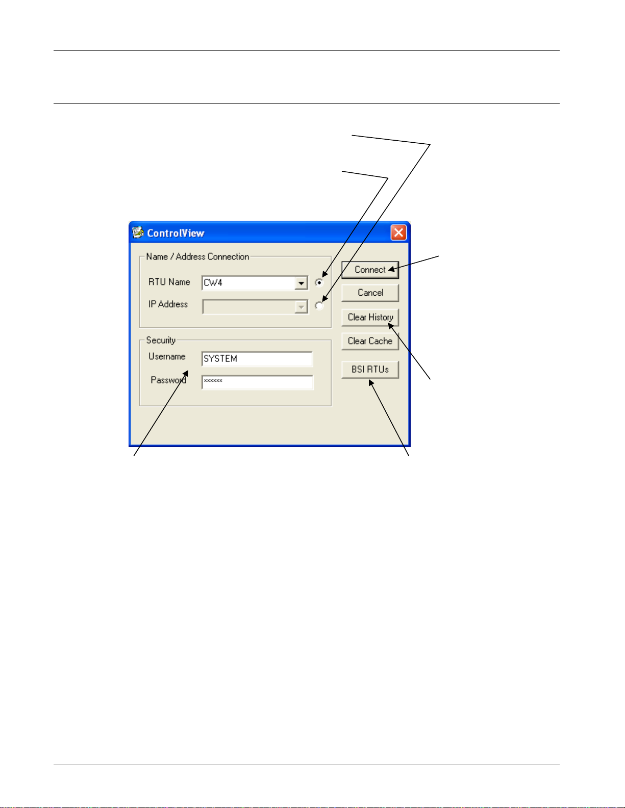
2.3 Establishing a Connection with the ControlWave and Uploading
File(s)
Select this button to enter the IP address
-orSelect this button to use the RTU name
You cannot enter both the IP address and
the RTU name
Click “Connect” to
establish the
connection and display
the files available for
upload.
You must provide a valid
username / password combination
to access the ControlWave.
The list controls allow you
to call up previous
entries. To erase the
previous entries, click
“Clear History.”
Not applicable in Field
1.
Tools.
Figure 2-2. ControlView
1. Field Tools automatically fills in the node name. If you’d rather
specify an IP address select the button to the right of the IP Address
field, then enter the ControlWave’s IP address in the IP Address
field (or use the list control to select it if it appears in the history list
of IP addresses).
2. Enter a valid Username / Password combination for this
ControlWave.
3. Click Connect and ControlView displays a list of files available for
upload from the ControlWave.
2-4 ControlView Issued Sep-2012

ControlWave Utilities Manual (D5142)
4. From the list box in the Select File to View dialog box, select the
file you want to view and click OK. ControlView uploads that file
to the PC and launches its application. (Note: If there is only one file
in the ControlView area of FLASH available for uploading, you
don’t have to select it; ControlView uploads it automatically and
launches its associated application.)
Select which file you want
to upload and click OK.
Figure 2-3. Selecting File to Upload
Note: If the file you upload is a zipped (compressed) file, ControlView
automically uncompresses the file; the application it launches
depends on entries in the STARTUP.INI file.
Issued Sep-2012 ControlView 2-5

This page is intentionally left blank

ControlWave Utilities Manual (D5142)
Chapter 3 – Using DataView
DataView allows you to collect several types of data from a
ControlWave series controller, including signal data, signal lists, archive
data, array values, and audit trail alarm/event information. In addition, it
allows you to search for signals based on various criteria, and also
allows you to send recipes (lists of signal values) to the controller.
In This Chapter
3.1 Starting DataView ............................................................................ 3-2
3.2 Using the Tool Bar within DataView ................................................ 3-2
3.3 Signing on to a Node ....................................................................... 3-3
3.4 Printing the Entries in the Current DataView Window ..................... 3-3
3.5 Exporting Data Entries to the Windows Clipboard ....................... 3-3
3.6 Conducting a Signal Search ............................................................ 3-4
3.6.1 Starting the Signal Search .................................................... 3-4
3.6.2 Saving Search Criteria ......................................................... 3-9
3.6.3 Retrieving Search Criteria .................................................... 3-9
3.6.4 Altering Search Criteria ........................................................ 3-9
3.7 Viewing Entries in a Signal Window .............................................. 3-10
3.7.1 Changing Signal Values in the Signal Window .................. 3-11
3.7.2 Changing Signal Inhibit/Enable Bits in the Signal Window 3-12
3.7.3 Changing Floating Point Format of Data in Signal Window3-12
3.8 Displaying a Remote Signal List .................................................... 3-13
3.8.1 Selecting a Different Remote Signal List ............................ 3-13
3.8.2 Changing Remote List Signal Values ................................. 3-13
3.9 Creating and Using DataView Lists ............................................... 3-14
3.9.1 Creating a DataView List .................................................... 3-14
3.9.2 Collecting Live Data into the DataView List ....................... 3-15
3.9.3 Saving the DataView List ................................................... 3-15
3.9.4 Viewing a Previously Saved DataView List ........................ 3-15
3.10 Creating and Using Recipes .......................................................... 3-15
3.10.1 Creating a Recipe ............................................................... 3-15
3.10.2 Saving the Recipe .............................................................. 3-16
3.10.3 To View/Modify an Existing Recipe File ............................. 3-17
3.10.4 To Update Signals in the Controller with the Recipe Values 3-17
3.10.5 To Read the Current Signal Values From the Controller ... 3-17
3.10.6 To Cancel Unsaved Modifications to the Recipe Values ... 3-17
3.10.7 Changing the Floating Point Format of Data ...................... 3-17
3.11 Viewing Data for a Single Signal ................................................... 3-18
3.11.1 Acknowledging an Alarm .................................................... 3-19
3.12 Viewing Data Arrays ...................................................................... 3-19
3.12.1 Changing Values in the Data Array .................................... 3-20
3.12.2 Toggling the Time/Value Format ........................................ 3-21
3.12.3 Keeping Column 1 Visible While Scrolling Through the Array3-21
3.12.4 Calling Up a Different Data Array ....................................... 3-21
3.12.5 Changing the Floating Point Format .................................. 3-21
3.13 Viewing Audit Trail Records ........................................................... 3-21
3.14 Viewing Archive Data Files ............................................................ 3-24
3.14.1 Keeping Column 1 Visible .................................................. 3-25
3.14.2 Calling Up a Different Archive File ..................................... 3-25
3.14.3 Changing the Floating Point Format .................................. 3-25
3.14.4 Restrictions on Archive File Size ........................................ 3-25
Issued Sep-2012 DataView 3-1
ControlWave Utilities Manual (D5142)
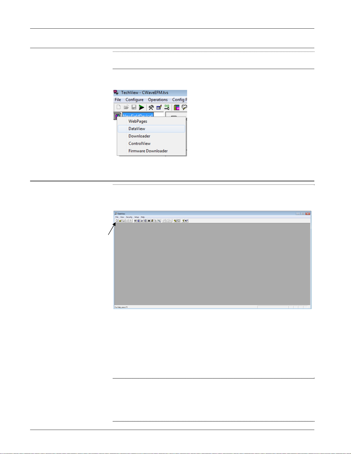
3.1 Starting DataView
Note: Before starting DataView, you must establish communications
with the controller using Field Tools, then launch TechView.
Right click on the RTU name in TechView then choose DataView from
the pop-up menu.
3.2 Using the Tool Bar within DataView
The DataView window includes a tool bar which provides you easy
access to DataView's features and functions, and serves as an alternative
to using the menu bar and pull down menus.
Toolbar
Figure 3-1. DataView
If you position the mouse cursor over any tool bar icon you can see a
label which identifies the icon's function. (Note: The number and
function of active icons in the tool bar varies depending upon which
DataView feature currently runs in the window.) A single click on the
icon activates its feature. See the pages which follow for a description of
the various DataView features.
Notes:
You can run multiple DataView functions simultaneously in
separate windows, if sufficient memory is available.
If sufficient memory is available, you can run multiple copies of
DataView simultaneously.
3-2 DataView Issued Sep-2012
ControlWave Utilities Manual (D5142)
3.3 Signing on to a Node
When invoked from within Field Tools, DataView automatically uses
the Field Tools RTU credentials; so you do not need to sign on.
The Automatic Sign-on feature does not apply when launching
DataView through Field Tools.
3.4 Printing the Entries in the Current DataView Window
You can print the textual data displayed in the various types of
DataView Windows on a printer.
Notes:
Before attempting to print, you must configure a printer and connect
it to this workstation, either directly, or through a network. To
access the Windows Print Setup dialog box, click File > Print
Setup.
The types of DataView windows which hold printable data include
Signal windows (which are used to display Signal Searches,
DataView Lists, or Remote Lists) as well as other types of windows
such as Audit Trail windows, Archive windows, and Array
windows. All of these types of windows will be discussed later in
this manual.
To preview the data you want to print, click File>Print Preview from
the menu bar.
To print the entries (data) in the current DataView window, click the
printer icon, shown above, or click File>Print. The Windows Print
dialog box opens. See your Windows™ documentation for further
information.
3.5 Exporting Data Entries to the Windows Clipboard
As an alternative to sending data to the printer, described above, you
can copy DataView window entries as text to the Windows Clipboard.
From the Clipboard, you can export the data to other Windows
applications such as spreadsheets or word processors. DataView formats
its entries specifically for use in Microsoft Excel.
To copy entries in the current DataView window to the Windows
Clipboard, click File>Copy to Clipboard.
See your Windows documentation for more information on using the
Clipboard.
Issued Sep-2012 DataView 3-3
ControlWave Utilities Manual (D5142)
3.6 Conducting a Signal Search
A signal search allows you to search for all signals (variables) which
share one or more common characteristics. For example, you can define
the search criteria to be all signals which share the same signal
extension and are control-inhibited. Or you could search for all signals
currently in the high-high alarm state. The following is a list of valid
signal search criteria:
Signal base name, extension, or attribute (ControlWave configured
to use ACCOL names)
Variable/function block instance name
String Search
Current alarm state (logical alarm, high, high-high, low, low-low)
Inhibit/enable bit status (alarm inhibit/enable, control inhibit/enable,
manual inhibit/enable)
Questionable data bit status
3.6.1 Starting the Signal Search
To start a Signal Search, click on the Signal Search tool bar icon (shown
at left), or click File > New, and then click Signal Search in the New
list box. Either method opens the Signal Search Properties dialog box.
Field Tools automatically populates the Node name field. Use the other
fields to specify the parameters of your search.
Notes:
To see all variables in the project (both global and local variables
marked as “PDD”) you can leave all the selection fields blank.
Some of the searches support wildcard characters. Wildcard
characters allow you to search for items for which you don’t know
the exact name, or for which there may be several possible matches.
There are two wildcard characters supported, “*” and “?”
The * indicates that DataView should automatically consider any
characters in the position where the * appears as valid matches for
this search. For example, if you search for “COMP*,” items like
“COMP4,” “COMPRESSOR” and “COMPORT” are all considered
valid matches.
The ? indicates that DataView should accept the substitution of any
one single character for the question mark as a valid match for this
search. For example, if you search for “PUMP?RUN” then
“PUMP1RUN,” “PUMP2RUN” or “PUMPNRUN” are all
considered valid matches.
3-4 DataView Issued Sep-2012
ControlWave Utilities Manual (D5142)
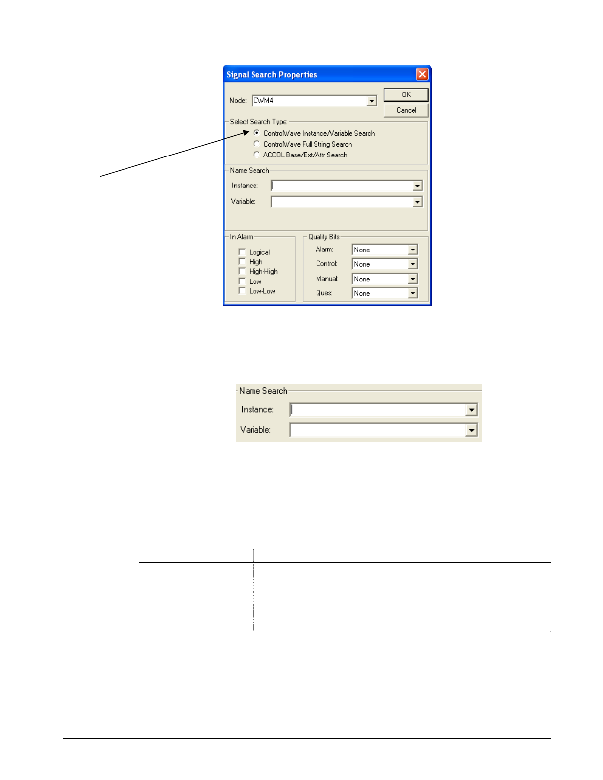
Choose the type of
search you want to
conduct.
Figure 3-2. Signal Search Properties dialog box
Instance/Variable
Search Mode:
For ControlWave controllers you can search based on the POU
Instance name(s), and/or the Variable name. You can use
wildcards in either of these fields.
The same variable can have multiple instance names associated
with it, for example, an instance for the program, followed by the
instance for a function block, etc. A period “.” character follows
each instance therefore an instance name is always to the left of
the last period. DataView considers the portion to the right of the
last period to be the variable name. The signal search can only
find variables which you previously marked as “PDD.”
Field Description
Instance
Variable
You can enter up to 32 characters in the Instance name portion. If
you do NOT use wildcard characters, the instance name must match
exactly to be considered a valid match. For global variables the POU
instance name must be “@GV.” If you leave the Instance field blank,
DataView considers any instance name to be valid, and it only uses
the Variable field in the search.
You can enter up to 32 characters in the Variable name portion. If you
do NOT use wildcard characters, the variable name must match
exactly to be considered a vali d mat ch. If y ou le ave the Variabl e field
blank, DataView only uses the Instance field in the search
Some Examples:
Issued Sep-2012 DataView 3-5

ControlWave Utilities Manual (D5142)
e
Let’s say you have a set of variables with the following names (Figure
3-3).
instance
name
multiple
instance
names
@GV.PRESSURE_READING
@GV.MYFB.STATION1_FLOW
@GV.MYFB.STATION2_FLOW
@GV.MYFB.STATION3_FLOW
@GV.MYFB.STATION4_FLOW
@GV.MYFB2.STATION1_FLOW
@GV.MYFB2.STATION2_FLOW
@GV.MYFB2.STATION3_FLOW
@GV.MYFB2.STATION4_FLOW
PROG1.TEMP_HIGH
PROG1.TEMP_LOW
PROG1.TEMP_CURRENT
instance
name
variable name
variable nam
variable name
Figure 3-3. Sample Set of Variables
Table 3-1 lists some resulting matches for searches based on this set of
variables:
Table 3-1. Sample Search Results – Instance / Variable
If you enter
this in the
Instance field
* STATION1* @GV.MYFB.STATION1_FLOW
leave blank
@GV.MYFB* STATION2* @GV.MYFB.STATION2_FLOW
PROG TEMP*
PROG*
And you enter this in
the Variable field
TEMP* PROG1.TEMP_HIGH
leave blank
DataView returns the
following variables from the
set of variables shown in
Figure 3-3.
@GV.MYFB2.STATION1_FLOW
PROG1.TEMP_LOW
PROG1.TEMP_CURRENT
@GV.MYFB2.STATION2_FLOW
No matches; because no wildcard
following ‘PROG’.
PROG1.TEMP_HIGH
PROG1.TEMP_LOW
PROG1.TEMP_CURRENT
@GV.MYFB2
*.* STATION3* @GV.MYFB.STATION3_FLOW
3-6 DataView Issued Sep-2012
leave blank
@GV.MYFB2.STATION1_FLOW
@GV.MYFB2.STATION2_FLOW
@GV.MYFB2.STATION3_FLOW
@GV.MYFB2.STATION4_FLOW
@GV.MYFB2.STATION3_FLOW

ControlWave Utilities Manual (D5142)
If you enter
this in the
Instance field
*
*.*
And you enter this in
the Variable field
leave blank
leave blank
DataView returns the
following variables from the
set of variables shown in
Figure 3-3.
@GV.PRESSURE_READING
@GV.MYFB.STATION1_FLOW
@GV.MYFB.STATION2_FLOW
@GV.MYFB.STATION3_FLOW
@GV.MYFB.STATION4_FLOW
@GV.MYFB2.STATION1_FLOW
@GV.MYFB2.STATION2_FLOW
@GV.MYFB2.STATION3_FLOW
@GV.MYFB2.STATION4_FLOW
PROG1.TEMP_HIGH
PROG1.TEMP_LOW
PROG1.TEMP_CURRENT
@GV.MYFB.STATION1_FLOW
@GV.MYFB.STATION2_FLOW
@GV.MYFB.STATION3_FLOW
@GV.MYFB.STATION4_FLOW
@GV.MYFB2.STATION1_FLOW
@GV.MYFB2.STATION2_FLOW
@GV.MYFB2.STATION3_FLOW
@GV.MYFB2.STATION4_FLOW
*.MYFB2
leave blank
or
*
*.MYFB2* STATION2_FL?W @GV.MYFB2.STATION2_FLOW
PROG?
@GV.MYFB?
leave blank
STATION?_FLOW @GV.MYFB.STATION1_FLOW
leave blank
leave blank
@GV.MYFB2.STATION1_FLOW
@GV.MYFB2.STATION2_FLOW
@GV.MYFB2.STATION3_FLOW
@GV.MYFB2.STATION4_FLOW
@GV.MYFB.STATION2_FLOW
@GV.MYFB.STATION3_FLOW
@GV.MYFB.STATION4_FLOW
@GV.MYFB2.STATION1_FLOW
@GV.MYFB2.STATION2_FLOW
@GV.MYFB2.STATION3_FLOW
@GV.MYFB2.STATION4_FLOW
PROG1.TEMP_HIGH
PROG1.TEMP_LOW
PROG1.TEMP_CURRENT
@GV.MYFB.STATION1_FLOW
@GV.MYFB.STATION2_FLOW
@GV.MYFB.STATION3_FLOW
@GV.MYFB.STATION4_FLOW
@GV.MYFB2.STATION1_FLOW
@GV.MYFB2.STATION2_FLOW
@GV.MYFB2.STATION3_FLOW
@GV.MYFB2.STATION4_FLOW
Issued Sep-2012 DataView 3-7
ControlWave Utilities Manual (D5142)
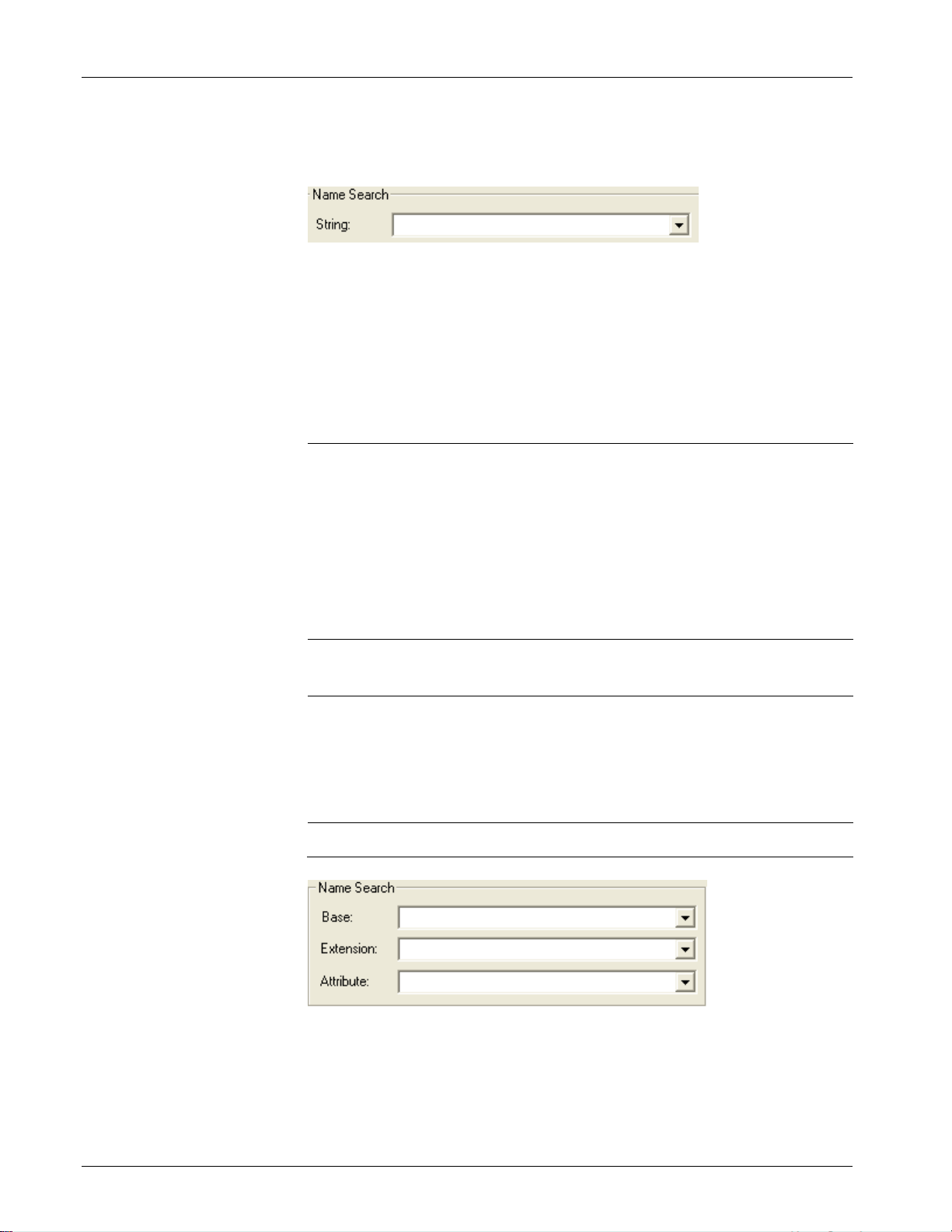
ControlWave Full
String Search
Mode:
For this search, you can enter a string that is in either the instance name
or variable name.
The search string you enter can include wildcards to establish a pattern
for DataView to match.
Table 3-2 shows some examples, using the same set of variables from
Figure 3-3.
Table 3-2. Sample Search Results – String
If you enter
this in the
String field
DataView returns the following variables from the set
of variables shown in Figure 3-3.
*STATION?_F* @GV.MYFB.STATION1_FLOW
@GV.MYFB.STATION2_FLOW
@GV.MYFB.STATION3_FLOW
@GV.MYFB.STATION4_FLOW
@GV.MYFB2.STATION1_FLOW
@GV.MYFB2.STATION2_FLOW
@GV.MYFB2.STATION3_FLOW
@GV.MYFB2.STATION4_FLOW
ACCOL Base,
Extension, and
Attribute Search
Mode
*MYFB?.STA
TION2*
@GV.MYFB.STATION2_FLOW
@GV.MYFB2.STATION2_FLOW
*1* @GV.MYFB.STATION1_FLOW
@GV.MYFB2.STATION1_FLOW
PROG1.TEMP_HIGH
PROG1.TEMP_LOW
PROG1.TEMP_CURRENT
@GV.P* @GV.PRESSURE_READING
If DataView communicates with a ControlWave and you set the
_USE_ACCOL_NAME system variable in your ControlWave project to
TRUE, you can use the Base, Extension and Attribute fields. To work
properly in this case, though, the signal names you search for must fit
the ACCOL II signal naming convention, i.e. no more than eight alphanumeric characters for the base, no more than six for the extension, and
3-8 DataView Issued Sep-2012
ControlWave Utilities Manual (D5142)
no more than four for the attribute. In addition, characters such as the at
sign “@” cannot be included. The underscore “_” may work if it’s at the
end of the search parameter, but it will not work at the beginning of the
search parameter.
Notes:
Do not enter wildcard characters in this mode.
You must search using the complete, Base, Extension, or Attribute,
not part of it. For example, to search for an attribute of “FLOW,”
you must enter “FLOW,” not “FLO,” “FL,” or “F.”
In Alarm and
Quality Bits
The In Alarm check boxes let you select signals which share the same
alarm status.
The Quality Bits area list boxes allow you to select signals based on the
inhibit/enable status for each alarm, control, or manual inhibit/enable bit.
You can also select based on the Questionable data status.
Select the desired search criteria, and click OK to execute the search. A
signal window opens to display all signals/variables which share the
selected characteristics. See Viewing Entries in the Signal Window for
information on using the entries in this window to change signal values,
or to alter inhibit / enable bits. See Viewing Data for a Single Signal for
information on viewing more detailed signal information. Note: The
window can only display the first 5000 signals found.
3.6.2 Saving Search Criteria
Once the Signal Window opens you can save its associated signal search
criteria in a file by clicking on the icon, shown at left, or you can click
File>Save As. Enter a name for the search criteria file, with an extension
of .SCH. You can save subsequent modifications to the SCH file if you
click on the same icon, or click File>Save.
3.6.3 Retrieving Search Criteria
DataView lists the names of the last four files viewed (of all file types)
in the File pull down menu. If the search criteria (.SCH) file you want to
view appears in the menu, you can open the file by simply clicking on
the file name. To call up any other search criteria (SCH) file, click the
icon, shown at left, or click File>Open. Select the desired SCH file from
the windows Open File dialog box, and click the Open button.
3.6.4 Altering Search Criteria
Once the Signal Window opens, you can change the search criteria by
Issued Sep-2012 DataView 3-9
clicking on the Properties tool bar icon, shown at left, or by clicking on
Format>Properties. The Signal Search Properties dialog box re-opens
to allow you to define new search criteria.
ControlWave Utilities Manual (D5142)
ON/O
t)
tes to controller
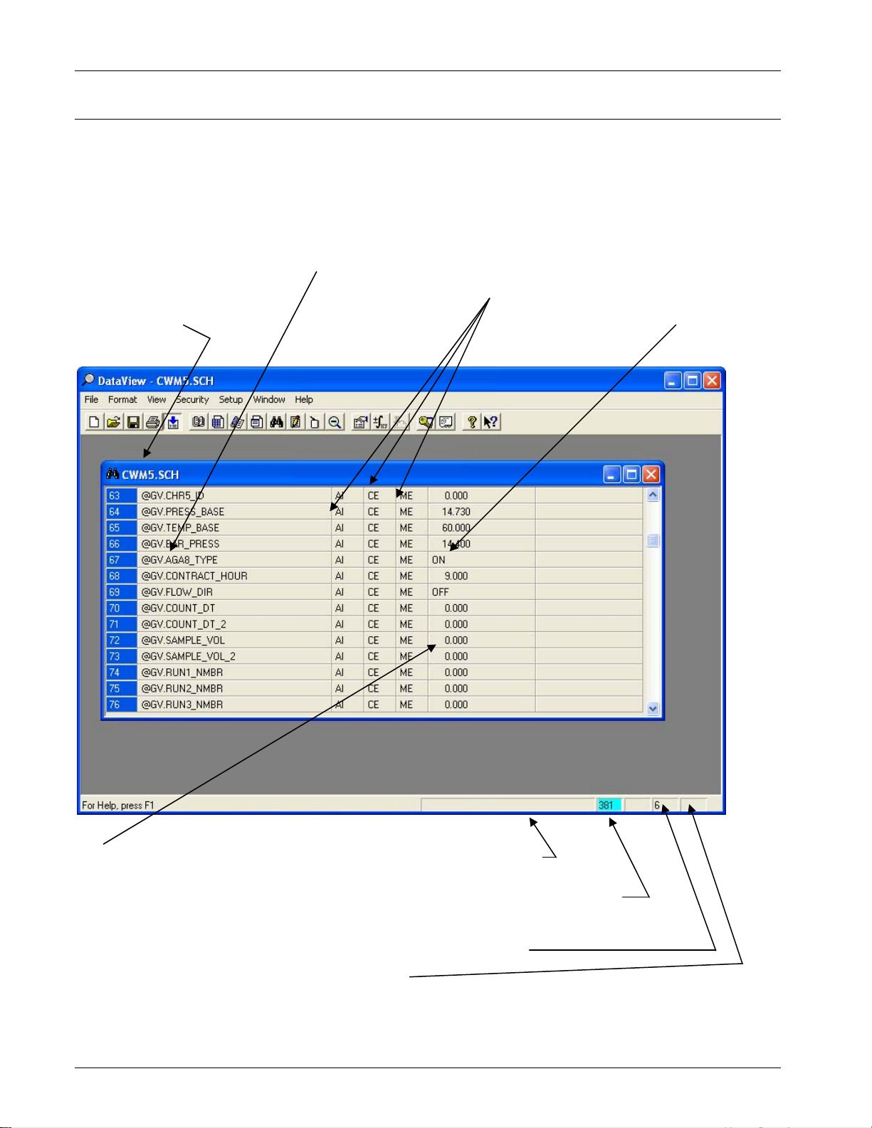
3.7 Viewing Entries in a Signal Window
DataView displays Remote Signal Lists, DataView Lists, and Signal
Searches in a signal window. You can view detailed signal information,
change signal values, or alter the inhibit/enable bits by clicking on those
fields for a particular entry in the signal window. Use the scroll bar to
view any entries not currently visible on the screen. The figure below
summarizes the elements in a signal window.
Signal Name (click
File name for the
signal search
on to get more
detailed info)
Inhibit/Enable status
bits (click on them
to change status)
Units Text (or
FF tex
Signal Value
(click on the
value to
change it)
(If value appears in red, signal
is “in-alarm;” if “!” appears,
alarm has not been
acknowledged by the central
computer (HMI/SCADA
package)
Number of pending
wri
Error/Status
Message area
Number of entries collected
Current
operator
security level
Figure 3- 4. Signal Window
3-10 DataView Issued Sep-2012
ControlWave Utilities Manual (D5142)
Notes:
For information on viewing detailed signal information, see Viewing
Data for a Single Signal, later in this section.
For Remote Signal Lists, and Signal Searches, the number of entries
which have been collected are displayed at the bottom of the
window in the status bar. If this value appears with a cyan (light
blue) background, then there are additional entries in the controller
which have not yet been collected
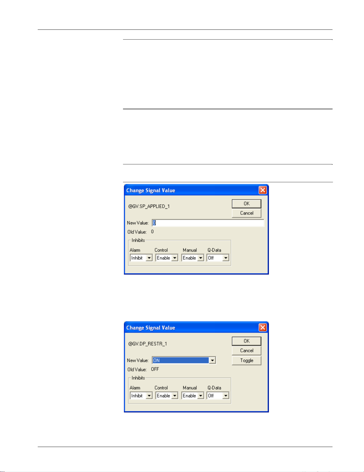
3.7.1 Changing Signal Values in the Signal Window
Click on the signal value you want to change. The Change Signal Value
dialog box opens to allow you to change the signal value, as well as the
manual, control, and alarm inhibit/enable bits, and the questionable data
bit.
Note To change a signal value, you must manually enable the signal (if
it isn’t already).
Figure 3-5. Change Signal Value – Analog
If the signal you want to change is a logical signal, you can either use
the list box to select the new state, or you can simply click on the
Toggle push button.
Figure 3-6. Change Signal Value – Logical
Issued Sep-2012 DataView 3-11
ControlWave Utilities Manual (D5142)
Note: The questionable data bit for logical signals can only be changed
through this dialog box; there is no automatic questionable
checking from the discrete I/O boards.
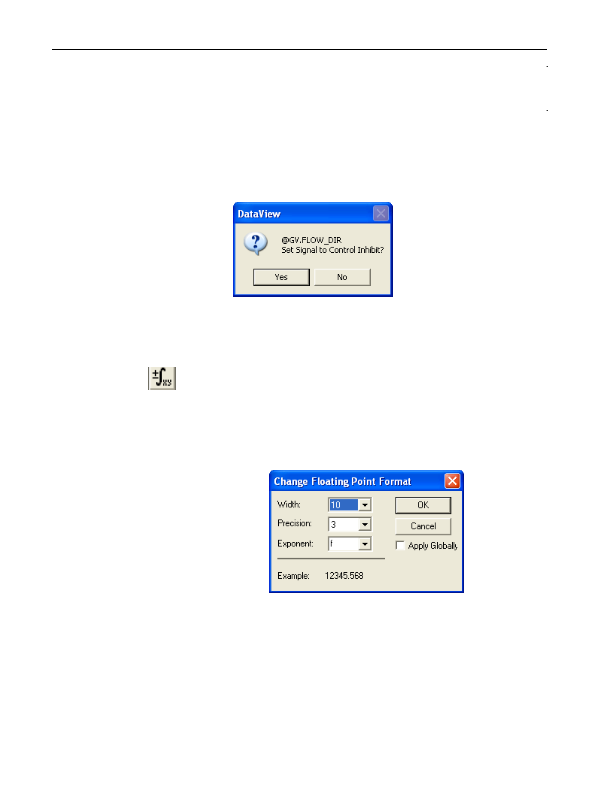
3.7.2 Changing Signal Inhibit/Enable Bits in the Signal Window
Click the inhibit/enable bit you would like to change. DataView
prompts you to confirm that you want to change the inhibit/enable
status. You can also change the inhibit/enable status using the Change
Signal Value dialog box, above.
Figure 3-7. Change Inhibit/Enable Status
3.7.3 Changing the Floating Point Format of Data in the Signal
Window
The Signal Window (and certain other types of windows) displays
analog values according to a default floating point format. To alter this
default format, click on the Change Floating Point Format tool bar icon
(shown at left) or click Format > Floating Point. The Change Floating
Point Format dialog box opens. Use the Width list box to specify the
total number of characters in the field (including the decimal point) used
to display a floating point number.
Figure 3-8. Change Floating Point Format dialog box
Use the Precision list box to choose the number of places to the right of
the decimal point which the window should display.
Use the Exponent list box to choose floating point format f, exponential
notation e or choose g to have DataView choose the “best fit” format.
If you want the floating point format defined here to apply throughout
the DataView windows, check the Apply Globally check box.
3-12 DataView Issued Sep-2012
ControlWave Utilities Manual (D5142)
3.8 Displaying a Remote Signal List
The Signal Window (and certain other types of windows) displays
analog values according to a default floating point format. To alter this
default format, click on the Change Floating Point Format tool bar icon
(shown at left) or click Format Floating Point. The Change Floating
Point Format dialog box opens. Use the Width list box to specify the
total number of characters in the field (including the decimal point) used
to display a floating point number.
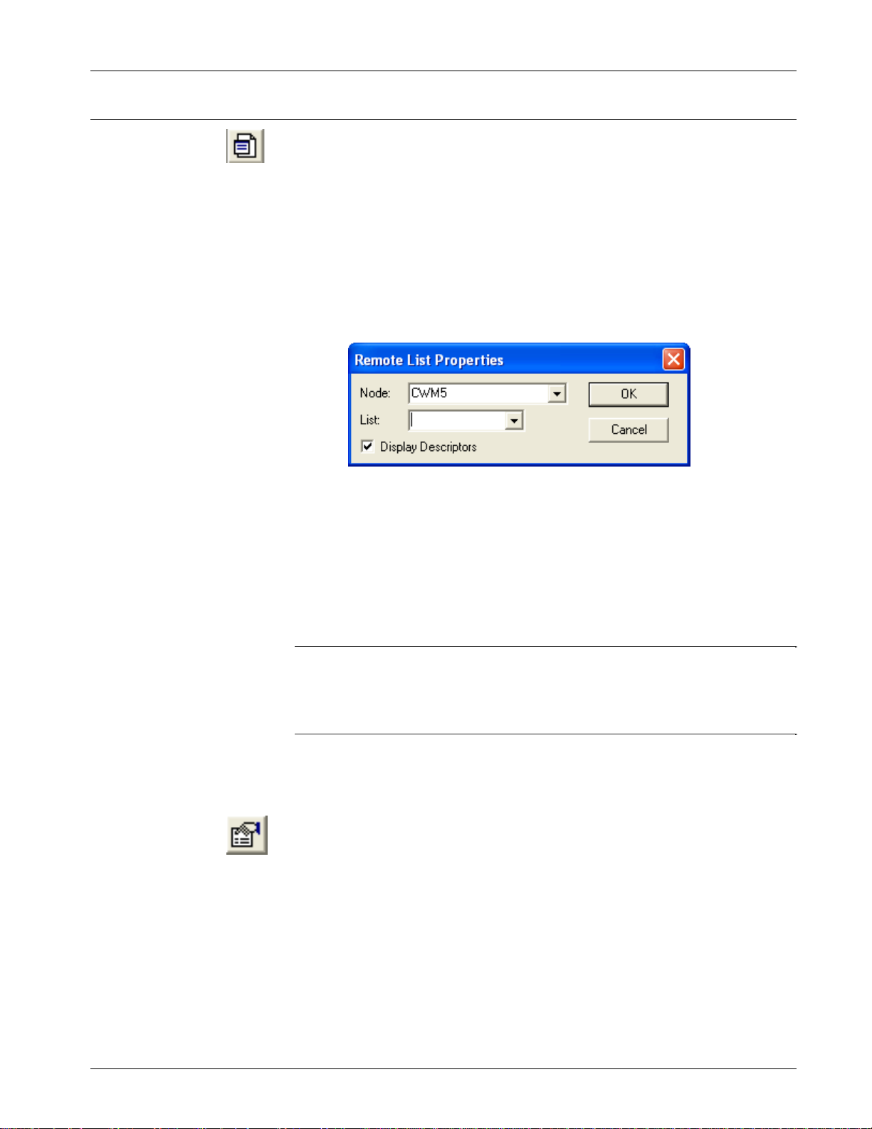
To view a signal list in the remote process controller, click the Remote
List tool bar icon, shown at left or click File>New. Choose Remote
List from the New list box.
Figure 3-9. Remote List Properties dialog box
You can use the List list box to see which signal lists exist in the
controller, and then select a list from it, or you can just type the list
number in the box; then click OK. A signal window opens containing
the signal list entries.
If you check Display Descriptors, signal descriptive text, if it exists,
appears in the signal window instead of the signal name.
Notes:
DataView cannot display more than 10,000 signals from a particular
list.
DataView cannot display lists numbered higher than 255.
3.8.1 Selecting a Different Remote Signal List
Once the Signal Window opens, you can recall the Remote List
Properties dialog box to call up a different list by clicking the Properties
icon, shown at left, or by clicking Format>Properties.
3.8.2 Changing Remote List Signal Values, Altering Inhibit/Enable
Bits
See Section 3.7 for information on using the entries in this window to
change signal values, or to alter inhibit/enable bits. See Viewing Data
for a Single Signal (later in this manual) for information on viewing
more detailed signal information.
Issued Sep-2012 DataView 3-13
ControlWave Utilities Manual (D5142)
3.9 Creating and Using DataView Lists
A DataView List is a file, stored on the PC, that contains the names of
signals, from a single controller, from which you would like to collect
data. You can open the DataView list file in DataView to collect and
display data for the designated signals.
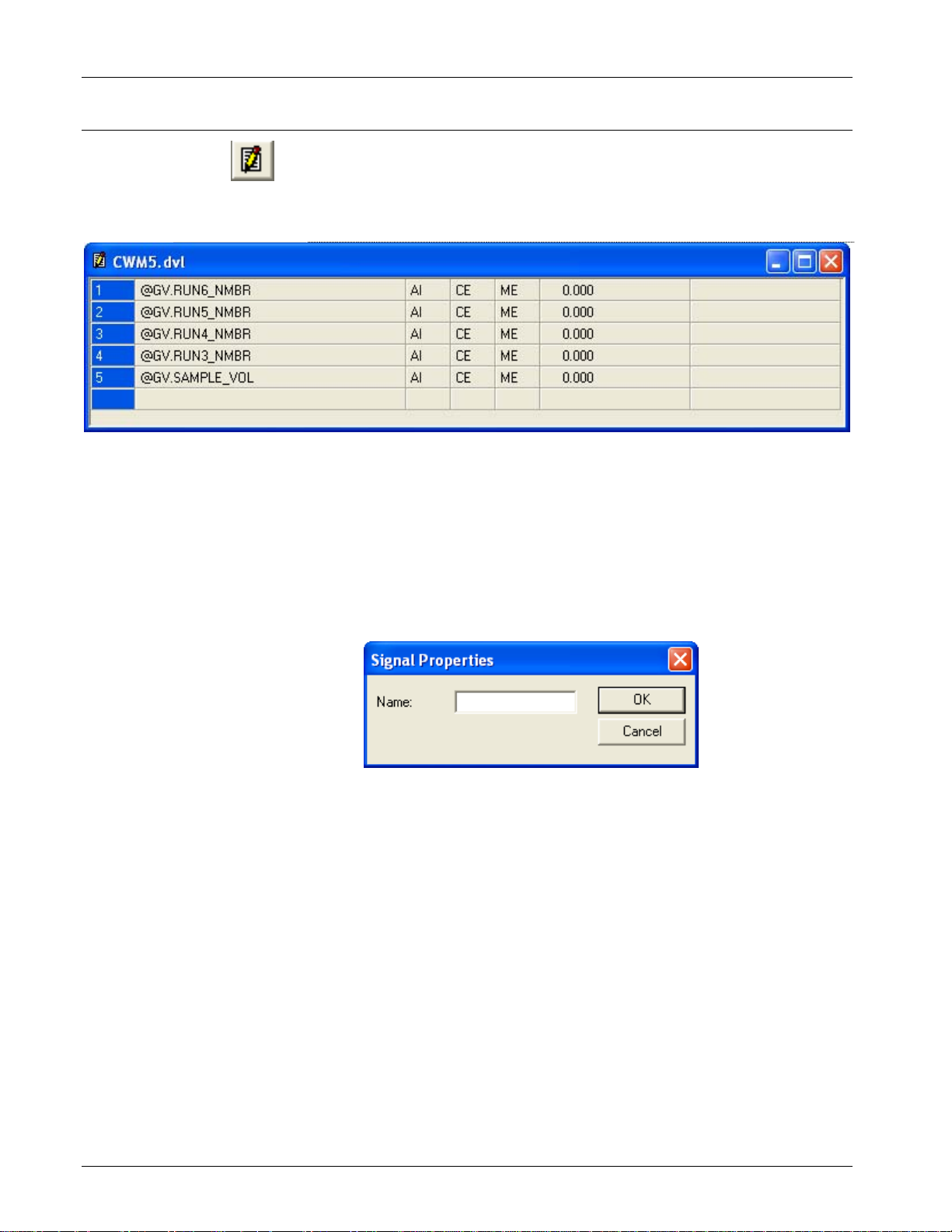
Figure 3-10. DataView List
3.9.1 Creating a DataView List
Click the DView List icon, shown above, or click File>New and then
click DView List in the New list box; in either case, an empty
DataView List signal window opens.
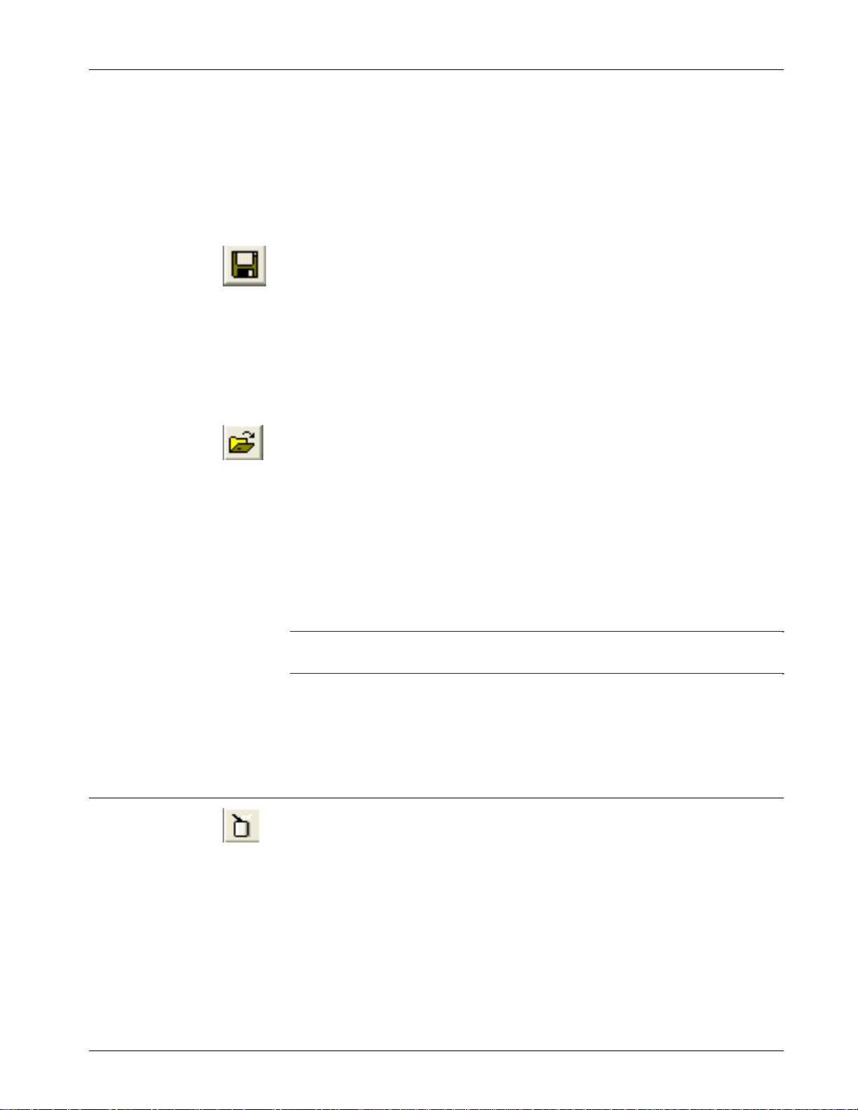
From the menu bar, click Edit>Insert, and the Signal Properties dialog
box opens.
Figure 3-11. Remote List Properties dialog box
Enter a signal name in the Name field, and click OK; the dialog box
inserts the signal on the currently highlighted line, and pushes down any
entries that begin on that line. Repeat this step for each additional signal
you want to include in the DataView List. Note: Be sure you include the
proper punctuation for the signal/variable.
If you make a mistake on a particular line, click on the line you want to
change, then click Edit>Modify; the Signal Properties dialog box reopens, allowing you to edit the signal name.
If you want to delete a particular line, click the line you want to delete,
and then click Edit>Delete. The system prompts you to confirm that
you want to delete the line from the DataView List; click Yes and the
system removes that signal from the DataView List.
3-14 DataView Issued Sep-2012
ControlWave Utilities Manual (D5142)
3.9.2 Collecting Live Data into the DataView List
The system suspends collection of DataView List data while you create
or modify the DataView List, or if certain error conditions exist. When
you finish creating/editing the list, you can activate collection if you
click View>Refresh.
3.9.3 Saving the DataView List
If this is a new DataView List, you must save it by clicking on the icon,
shown at left, or by clicking File>Save As. Assign a name to the
DataView List file using the Windows Save As dialog box. All
DataView Lists have a file extension of (.DVL).
To save modifications to a previously saved DataView List, click on
Save toolbar icon, shown above, or click File>Save.
3.9.4 Viewing a Previously Saved DataView List
The File pull down menu shows the names of the last four files viewed
(of all file types). If the DataView List (.DVL) file you want to view
appears in the menu, you can open the file simply by clicking on the file
name. To view any other DataView List (.DVL file), click the Open File
tool bar icon, shown above, or click File>Open. The Windows Open
File dialog box opens. Select the DataView List file, and click the Open
button. The selected DataView List displays on the screen. Assuming
TechView is already running, you can also open a DataView list by
double-clicking on the DVL filename in Windows.
Note: DataView cannot display more than 100 signals from a
DataView list.
See Section 3.7 for information on using the entries in this window to
change signal values, or to alter inhibit/enable bits. See Viewing Data
for a Single Signal (later in this manual) for information on viewing
more detailed signal information.
3.10 Creating and Using Recipes
A recipe is a list of signals, together with signal values, which DataView
stores in a file, on the PC. You call up the recipe file, within DataView,
and you can send the signal values to the remote process controller, to
update the current values of those signals in the controller. This provides
a quick way to change the values of several signals in a running load at
the same time.
3.10.1 Creating a Recipe
Click the Recipe icon, shown above, or click File>New, and select
Recipe from the New list box. An empty recipe window opens.
Issued Sep-2012 DataView 3-15
ControlWave Utilities Manual (D5142)
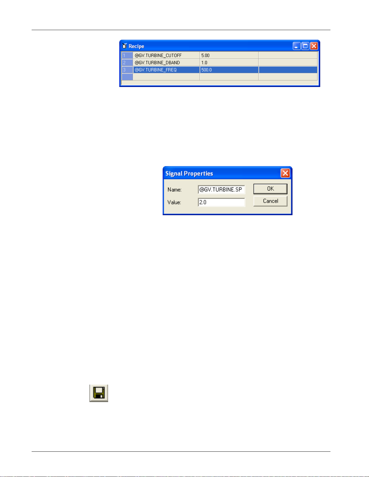
Figure 3-12. Recipe Window
Click Edit>Insert and the Signal Properties dialog box opens. Enter a
signal name in the Name field, and a value for the signal in the Value
field, then click OK. DataView inserts the signal on the currently
highlighted line, and pushes down any entries that begin on that line.
Repeat this step for each additional signal you want to include in the
Recipe.
Figure 3-13. Adding Signals to the Recipe
\\
Although DataView performs no verification with the remote load when
you create the recipe, you should remember that if you enter a logical
signal in the recipe, only two values are valid: 1.0 for ON, and 0.0 for
OFF.
If you make a mistake on a particular line, click on the line you want to
change, then click Edit>Modify; the Signal Properties dialog box
opens, allowing you to edit the signal name and/or value.
If you want to delete a particular line, click on the line you want to
delete, then click Edit>Delete. DataView prompts you to confirm that
you want to delete the line from the Recipe; click Yes and DataView
removes that signal from the Recipe.
Recipes can include up to 10,000 lines.
3.10.2 Saving the Recipe
When the Recipe is complete, you must save it by clicking on the icon,
shown at left, or click File>Save As. Assign a name to the Recipe file
using the Windows Save As dialog box. All Recipes have a file
extension of (.RCP).
To save modifications to a previously saved Recipe, click the Save
toolbar icon, shown above, or click File>Save.
3-16 DataView Issued Sep-2012
 Loading...