

Fisher IM Supplement: Single Point Calibration - DVC6200 HW2 Digital Valve Controller Manuals & Guides

Instruction Manual Supplement
D104490X012
Single Point Calibration
DVC6200 Digital Valve Controller
January 2020
Fisher
™
FIELDVUE™ DVC6200 HW2 Digital Valve
Controller
The Single Point Calibration procedure allows you to replace an existing positioner with a DVC6200 HW2, on
sliding-stem applications, without performing a travel calibration. This procedure should only be used in emergency
situations where a positioner must be completely replaced and is part of a valve assembly that does not have a process
bypass or the process cannot be shut down. For other procedures, refer to the DVC6200 Quick Start Guide and the
DVC6200 HW2 Instruction Manual.
Related Documents
D Fisher FIELDVUE DVC6200 Series Digital Valve Controllers Quick Start Guide (D103566X012)
D Fisher FIELDVUE DVC6200 HW2 Digital Valve Controller Instruction Manual (D103605X012
These documents are available from your Emerson sales office
or at Fisher.com.
WARNING
Personal injury or property damage, caused by unexpected valve movement and an uncontrolled process, could result if
this procedure is attempted when the valve is not locked at its present position. If you cannot safely lock the valve in
position until this procedure is complete, do not proceed with this procedure.
)
Notes
This procedure should only be used in emergency situations where a positioner must be completely replaced and is part of a valve
assembly that does not have a process bypass or the process cannot be shut down. Do not proceed if the valve has a bypass or the
process can be shut down.
The valve will need to be locked at its present position. This can be accomplished by using a handwheel or other mechanism. If the
valve assembly or valve application will not allow you to safely lock the valve in position until this procedure is complete, do not
proceed with this procedure.
This procedure can be used to replace a positioner with a DVC6200. The DVC6200 used to replace the existing positioner must
have firmware 2, 3, 4, 5, 6, or 7, hardware 2 and HC, AD, or PD diagnostic tiering. Do not proceed with this procedure if the digital
valve controller does not meet the tiering and firmware requirements mentioned above.
This procedure can only be performed on sliding-stem valve assemblies and only supports feedback connections using the linear
sliding-stem arrays. This procedure cannot be performed with a long stroke roller array. Do not proceed if you have something
other than a sliding-stem valve assembly with a linear sliding-stem array.
The Single Point Calibration procedure cannot be completed with Pressure Control. Do not proceed with this procedure if the
Travel/Pressure Control Mode is Pressure.
This procedure is not recommended for a valve assembly with a double-acting actuator that uses a DVC6200 with a Relay A that
was previously configured for a valve assembly with a single-acting actuator.
This procedure requires the use of ValveLink
™
software 13.5 or newer.
www.Fisher.com

DVC6200 Digital Valve Controller
January 2020
Instruction Manual Supplement
D104490X012
Installation
WARNING
Avoid personal injury or property damage from sudden release of process pressure or bursting of parts. Before proceeding
with any procedures:
D Always wear protective clothing, gloves, and eyewear to prevent personal injury or property damage.
D Do not remove or uncouple the actuator from the valve while the valve is still pressurized.
D The valve will need to be locked at its present position. If you cannot safely lock the valve in position until this procedure
is complete, do not proceed with this procedure.
D After the valve has been safely locked in position, disconnect any operating lines providing air pressure, electric power,
or a control signal to the actuator. Be sure the actuator cannot suddenly open or close the valve.
D Use lock‐out procedures to be sure that the above measures stay in effect while you work on the equipment.
D Check with your process or safety engineer for any additional measures that must be taken to protect against process
media.
1. Lock Valve in Place
1.1 Ensure the mounting kit for the replacement DVC6200 is compatible with the valve assembly. Do not proceed
with this procedure until you have obtained a mounting kit compatible with the replacement DVC6200 and the
control valve assembly.
1.2 Block the valve into position either with a handwheel or other mechanism. If you cannot safely lock the valve in
position until this procedure is complete, do not proceed with this procedure.
1.3 Disconnect the operating lines that provide air pressure to the actuator. Bleed any extra air that may be built up in
the instrument. Please note which air connections go to the actuator and which come from supply for future
reassembly.
1.4 Determine and record the following parameters:
D Feedback Connection
Note
This procedure only supports feedback connections using linear sliding-stem arrays. Do not proceed if you are not using a linear
sliding-stem array.
D Travel Sensor Motion: States whether increasing drive signal causes the magnetic assembly to move toward the
top of the instrument or away from the top of the instrument.
D Air (Closes/Opens)
: The magnetic array type that will be used with the replacement digital valve controller.
: States whether adding air opens or closes the valve.
D Actual Travel
: The measured distance from the closed position to the fully open position of the valve.
2. Configure Replacement Digital Valve Controller Prior to Installation
2.1 Open ValveLink software and connect to the replacement digital valve controller.
2

Instruction Manual Supplement
D104490X012
DVC6200 Digital Valve Controller
2.2 Open the tag for your replacement digital valve controller and run Setup Wizard.
2.2a Initiate the Setup Wizard from either the Instrument Setup menu or Setup Wizard Icon
on the toolbar.
2.2b Select the appropriate Travel/Pressure Control Mode and the Relay Type.
January 2020
D Travel/Pressure Control
: This defines the operating mode of the instrument as well as the behavior of
the instrument should the travel sensor fail. There are four choices:
d Travel Control- The instrument is controlling to a target travel. Fallback is not enabled.
d Pressure Control - The instrument is controlling to a target pressure. Fallback is not enabled.
d Fallback- Sensor Failure- The instrument will fallback to pressure control if the travel sensor failure
is detected.
d Fallback-Sensor / Tvl Deviation - The instrument will fallback to pressure control if the travel sensor
failure is detected, or if the Tvl Dev Press Fallback setting is exceeded for more than the Tvl Dev
Press Fallback Time.
D Relay Type
: The relay type is printed on the label affixed to the relay body.
d A = double-acting or single-acting
d B = single-acting, reverse
d C = single-acting, direct
Note
The Single Point Calibration procedure cannot be completed with Pressure Control. Do not proceed with this procedure if the
Travel/Pressure Control Mode is Pressure.
Travel/Pressure Control Mode must be set to Travel for double-acting actuators.
2.2c Set the desired Pressure Units and the Max Supply Pressure for the application.
2.2d Select the required Actuator Information including: Actuator Make, Actuator Model, Actuator Size, and
designate if a Volume Booster or Quick Release Valve is present.
2.2e If prompted, fill out any additional screens (eg: Zero Power Condition, Actuator Style, and Tuning
Information).
2.2f Select Yes when prompted to Use Factory Default Settings.
Note
It is not necessary to run an Auto Travel Calibration since the digital valve controller will be calibrated with the Single Point
Calibration feature in future steps and is not currently mounted to a valve assembly.
3

DVC6200 Digital Valve Controller
January 2020
2.2gWhen prompted to run an Auto Travel Calibration select No.
2.3 Place the instrument In Service and close the tag. Then disconnect the digital valve controller.
Instruction Manual Supplement
D104490X012
3. Manually Replace Positioner
WARNING
Refer to the Installation Warning on page 2.
3.1 Disconnect any operating lines that provide air pressure, electric power, or a control signal to the actuator. Be sure
the actuator cannot suddenly open or close the valve. Remember to note where each line goes for reassembly.
3.2 Confirm the valve assembly is safely locked in position. Do not proceed if the valve assembly has not been safely
locked in position.
3.3 Carefully remove the existing positioner without disturbing the mechanism locking the valve in position.
3.4 Mount the replacement digital valve controller by following the mounting instructions for sliding-stem valve
assemblies in the DVC6200 Quick Start Guide (D103566X012
).
CAUTION
Valve movement may occur if air is supplied to the digital valve controller during calibration. The Single Point Calibration
process cannot be started if air is supplied to the instrument.
3.5 Attach pneumatic and electrical operating lines to the replacement digital valve controller but Do Not Turn On Air
Supply.
D Measure and record the valve assembly’s Observed Travel (%). Observed Travel is the current position of the
valve as a percentage of the actual travel.
4. Run Single Point Calibration
4.1 In ValveLink software, connect to the replacement digital valve controller. Open the tag for your replacement
digital valve controller.
4.2 Initiate Single Point from the Calibration menu. Set the device Out of Service if prompted.
4.3 Read the Start Screen and confirm you have completed the required initial steps for Single Point Calibration. Click
Next if you have completed the required steps listed.
4.4 Review the travel configuration information pre-populated by Setup Wizard and/or enter the correct values in the
blanks on the Configuration Screen. Click Next when all the values are entered correctly.
4.5 Review the tuning information pre-populated by Setup Wizard and/or enter the correct values in the blanks on the
Tuning Screen. Click Next when all the values are entered correctly.
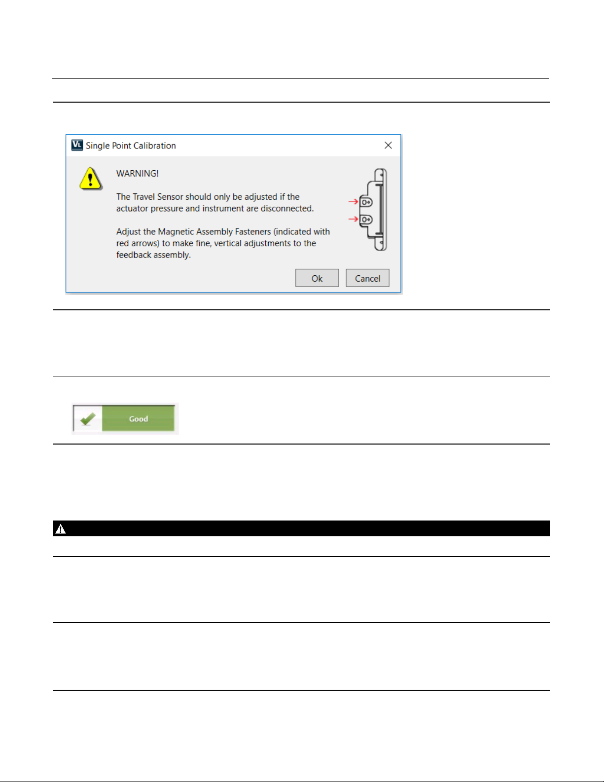
4.6 Read the Warning Screen (figure 1) that describes how to adjust the travel sensor. Click OK when finished reading
the screen.
4
Instruction Manual Supplement
D104490X012
DVC6200 Digital Valve Controller
Figure 1. Warning Screen
4.7 On the Travel Screen, enter the Actual Travel (in) and Observed Travel (%). Then click Next.
4.7a Read the alignment recommendations in the bottom left hand corner of the screen. Follow the alignment
recommendations, to move the feedback assembly up or down, until the alignment is indicated with the
good status symbol (Figure 2). Then click Next to put your digital valve controller back In Service.
January 2020
Figure 2. Good Status Symbol
4.8 Review the travel setpoint and measured travel on the Control Signal Screen. Adjust the travel setpoint to match
travel. This will minimize valve movement when air is resupplied. Once the travel setpoint matches travel, click
Next.
4.9 Reintroduce instrument air pressure to the digital valve controller. The air pressure supplied will be shown on the
dial graphic on the Air Screen. Once you’ve confirmed instrument air has been supplied, click Next.
WARNING
Refer to the Installation Warning on page 2.
4.10 On the resulting Finish Screen adjust the Travel Setpoint to remove force on the valve locking mechanism. Then
carefully remove the valve locking mechanism.
Note
The lack of a full travel calibration can impact the accuracy of the position feedback. While this does not impact the instrument’s
ability to control the process, it can influence the results of diagnostic tests.
This calibration is approximate and accuracy is limited. To ensure optimal accuracy and operation, perform an auto travel
calibration on the digital valve controller as soon as conditions allow.
5

DVC6200 Digital Valve Controller
January 2020
Instruction Manual Supplement
D104490X012
Neither Emerson, Emerson Automation Solutions, nor any of their affiliated entities assumes responsibility for the selection, use or maintenance
of any product. Responsibility for proper selection, use, and maintenance of any product remains solely with the purchaser and end user.
Fisher, FIELDVUE, and ValveLink are marks owned by one of the companies in the Emerson Automation Solutions business unit of Emerson Electric Co.
Emerson Automation Solutions, Emerson, and the Emerson logo are trademarks and service marks of Emerson Electric Co. All other marks are the property
of their respective owners.
The contents of this publication are presented for informational purposes only, and while every effort has been made to ensure their accuracy, they are not
to be construed as warranties or guarantees, express or implied, regarding the products or services described herein or their use or applicability. All sales are
governed by our terms and conditions, which are available upon request. We reserve the right to modify or improve the designs or specifications of such
products at any time without notice.
Emerson Automation Solutions
Marshalltown, Iowa 50158 USA
Sorocaba, 18087 Brazil
Cernay, 68700 France
Dubai, United Arab Emirates
Singapore 128461 Singapore
www.Fisher.com
6
E 2020 Fisher Controls International LLC. All rights reserved.
 Loading...