

IM Supplement: Simulation of Process Conditions for Calibration of Fisher Level Controllers and Transmitters (249 Sensors)
Fisher IM Supplement: Simulation of Process Conditions for Calibration of Fisher Level Controllers and Transmitters (249 Sensors) Manuals & Guides

Instruction Manual Supplement
D103066X012
249 Sensors
September 2017
Simulation of Process Conditions for Calibration
™
of Fisher
Level Controllers and
Transmitters—Supplement to 249 Sensor
Instruction Manuals
Displacer / torque tube sensors are transducers that convert a buoyancy change into a shaft rotation. The change in
buoyancy is proportional to the volume of fluid displaced, and the density of the fluid. The change in rotation is
proportional to the change in buoyancy, the moment arm of the displacer about the torque tube, and the torque rate.
The torque rate itself is a function of the torque tube material, the temperature of the material, the wall thickness, and
the length. If the density of the process fluid, process temperature, and torque tube material of the sensor are known,
simulation of process conditions may be accomplished by one of the following means
1. Weight or Force Method:
The interface application is the most general case. The level application can be considered an interface with the upper
fluid SG = 0, and the density application can be considered as a variable SG application with the interface at the top of
the displacer. The buoyancy for a given interface level on the displacer is given by:
(1)
:
=
F
B
Where:
F
B
ρ
w
V
D
H
disp
SG
U
SG
L
* V
*
ρ
w
SGU)H
D
[
= buoyant force
= density of water at 4_C, 1
atmosphere = 1.0000 Kg/liter
(0.03613 lb/in
= displacer volume
= height of interface on displacer,
normalized to displacer length
= specific gravity of upper fluid
(0.0 for Level)
= specific gravity of lower fluid
disp
SG
*
(
3
)
L
- SG
(1)
)
U
]
Figure 1. Cutaway View of Fisher 249 Displacer
Sensor
DRIVER ROD
TORQUE TUBE
SUSPENSION ROD
LIQUID DISPLACER
W2141-1
1. Note that this document does not consider the effects of the thermal expansion of
the moment arm, or the thermal expansion of displacer volume.
www.Fisher.com

249 Sensors
September 2017
Instruction Manual Supplement
D103066X012
Figure 2. Fisher 2500 or 2503 Level Controller
Transmitter on Caged 249 Sensor
2500 OR 2503
CONTROLLER/
TRANSMITTER
249 SENSOR
W8334
For the density application, H
= 1.0, SGu = lowest expected density, and SGL becomes the independent variable, the
disp
Figure 3. FIELDVUE™ DLC3010 Digital Level
Controller
actual process density.
The net load on the driver rod is then computed from the equation:
W7977-2
(2)
net
=
W
- F
D
B
W
Where:
W
W
net
D
= net load on driver rod
= weight of displacer
To simplify equations in the following discussion, let us define a few intermediate terms:
The minimum buoyancy, developed when the interface level is at the bottom of the displacer, is given by:
(3)
SG
V
*
FB
min
ρ
=
*
w
U
D
The change in buoyant force as the normalized interface level rises on the displacer is:
(4)
ΔF
=
ρ
*
V
B
w
D
- SGU) *
(SG
*
L
H
disp
The maximum change in buoyancy, developed when the interface level is at the top of the displacer is:
(5)
B)max
=
ρ
*
V
*
(SG
- SGU)
w
D
L
(ΔF
2

Instruction Manual Supplement
D103066X012
249 Sensors
September 2017
Temperature Effect
As process temperature increases, the torque rate decreases due to the change in modulus of rigidity. This effect can
be represented by normalizing the modulus vs. temperature curve for a given material to the room temperature value,
and using it as a scale factor on the torque rate. See figure 4 and table 1 or 2.
Because we can simulate the rotation of a more compliant torque tube by increasing the load, the weight value may be
divided by the same scale factor to simulate the process condition:
(6)
W
- F
D
W
Where:
W
net_test
G
norm
net_test
=
= net load adjusted to simulate
process temperature effect
= normalized modulus of torque
tube material, a function of
temperature.
G
B
norm
Displacer Rise Effect
Note that equation 6 simulates the process level on the displacer. The actual level in the cage or vessel will be
different, due to the rise of the displacer as the torque tube load is decreased by the increasing buoyancy.
On a 14‐inch displacer, or on a 249VS with a long driver rod, the displacer rise can become a significant fraction of the
span. If the torque tube rate and driver rod length are known, change in rotation can be computed by dividing the
torque change by the rate.
(7)
*
ΔF
ΔAngle
=
R
Where:
ΔAngle = resulting change in torque tube
Driver = driver rod length
R
amb
= Torque rate (torque per
Driver
B
amb
*
G
norm
(
*
angle in radians
_rotation) at ambient
temperature
π
/
180_
)
3

249 Sensors
Instruction Manual Supplement
September 2017
Figure 4. “Gnorm”: Theoretical Temperature Effect on Torque Rate for Most Commonly Used Materials
TORQUE RATE REDUCTION
1.00
0.98
0.96
0.94
(NORMALIZED MODULUS OF RIGIDITY)
D103066X012
0.92
0.90
norm
G
0.88
0.86
0.84
0.82
0.80
20 40 60 80 100 120 140 160 180 200 220 240 260 280 300 320 340 360 380 400 420
TEMPERATURE (_C)
TORQUE RATE REDUCTION
(NORMALIZED MODULUS OF RIGIDITY)
1.00
0.98
0.96
0.94
0.92
norm
0.90
G
0.88
N05500
N06600
N10276
S31600
N05500
N06600
N10276
0.86
0.84
0.82
0.80
50 100 150 200 250 300 350 400 450 500 550 600 650 700 750 800
S31600
TEMPERATURE (_F)
NOTE: THIS CHART DEPICTS THE REVERSIBLE CHANGE ONLY. THE IRREVERSIBLE DRIFT IS A FUNCTION OF THE NET LOAD, THE ALLOY, AND THE LEVEL OF STRESS EQUALIZATION
ACHIEVED IN MANUFACTURING. (THE IRREVERSIBLE EFFECT CAN ONLY BE COMPENSATED BY PERIODIC ZERO TRIM.) N05500 IS AN APPROPRIATE SPRING MATERIAL FOR
TEMPERATURES BELOW AMBIENT AND UP TO 232_C (450_F). ABOVE 260_C (500_F), THE INDUSTRY DOES NOT RECOMMEND USING IT AS A SPRING MATERIAL. N06600 IS
CONSIDERED ACCEPTABLE TO APPROXIMATELY 399_C (750_F) WITH PROPER STRESS EQUALIZATION.
4

Instruction Manual Supplement
D103066X012
249 Sensors
September 2017
Recognizing that the displacer rise is the side opposite this changing angle, in a triangle of which the drive rod is the
hypotenuse, the displacer rise can be approximated applying the small‐angle sine approximation to the result of
equation 7.
(8)
ΔRise
disp
2
R
B
amb
*
(
Driver
G
*
norm
)
ΔF
=
*
π
180_
The above expression may be factored to produce an ambient‐temperature displacer‐rise rate.
(9)
RiseRate
amb
π
180_
R
)
amb
*
(
/
=
Driver
2
The net rise is then restated with aid of the temperature correction term Gnorm.
(10)
ΔRise
disp
ΔF
=
B
RiseRate
*
G
norm
amb
The digital instrument firmware makes an internal correction for the displacer rise, so we must account for it in our
weight calculation to make sure that we get the expected digital value of interface level in the cage. (Analog electronic
and pneumatic devices don't have this correction capability, but the accuracy of the calibration would still be improved
by accounting for the effect during simulation.) The ratio of the level change on the displacer to the level change in the
cage needed to produce it is:
(11)
L
)
max
D
*
RiseRate
amb
G
/
norm
ΔH
ΔH
disp
cage
proc
=
)
L
ΔF
(
D
B
Where:
L
D
H
cage
The above equation is valid only for 0.0 < H
= length of displacer
= interface level in cage, normalized to displacer length.
< 1.0 (since interface level excursions above or below the displacer
disp
produce no additional change in buoyancy)
The % span error introduced by neglecting the displacer rise effect becomes smaller as the displacer length increases.
The displacer rise at the initial condition, (displacer completely submerged in the upper fluid), is given by:
(12)
RiseRate
Rise
0proc
FB
min_eff
=
G
*
norm
amb
Where:
FB
min_eff
W
max
Max( (W
disp
W
= [ FB
= the load that will cause the linkage to contact the lower travel stop.
), 0.0 ) = the amount of buoyancy required to lift the displacer off the travel stop so that rise can
max
Max( (W
min
disp
W
max
), 0.0) ]
actually commence. The maximum available shift below the zero rest position at ambient temperature is also limited
by this travel stop, so the value of W
(W
max_ambient
Note that W
* G
norm
max_ambient
) in the FB
min_eff
would have to be determined by experiment on the specific physical hardware, but for a first
will be a function of temperature. To account for this, replace W
max
equation.
max
by
approximation, you could use the ‘maximum unbuoyed displacer weight’ value given in table 5.
5
249 Sensors
September 2017
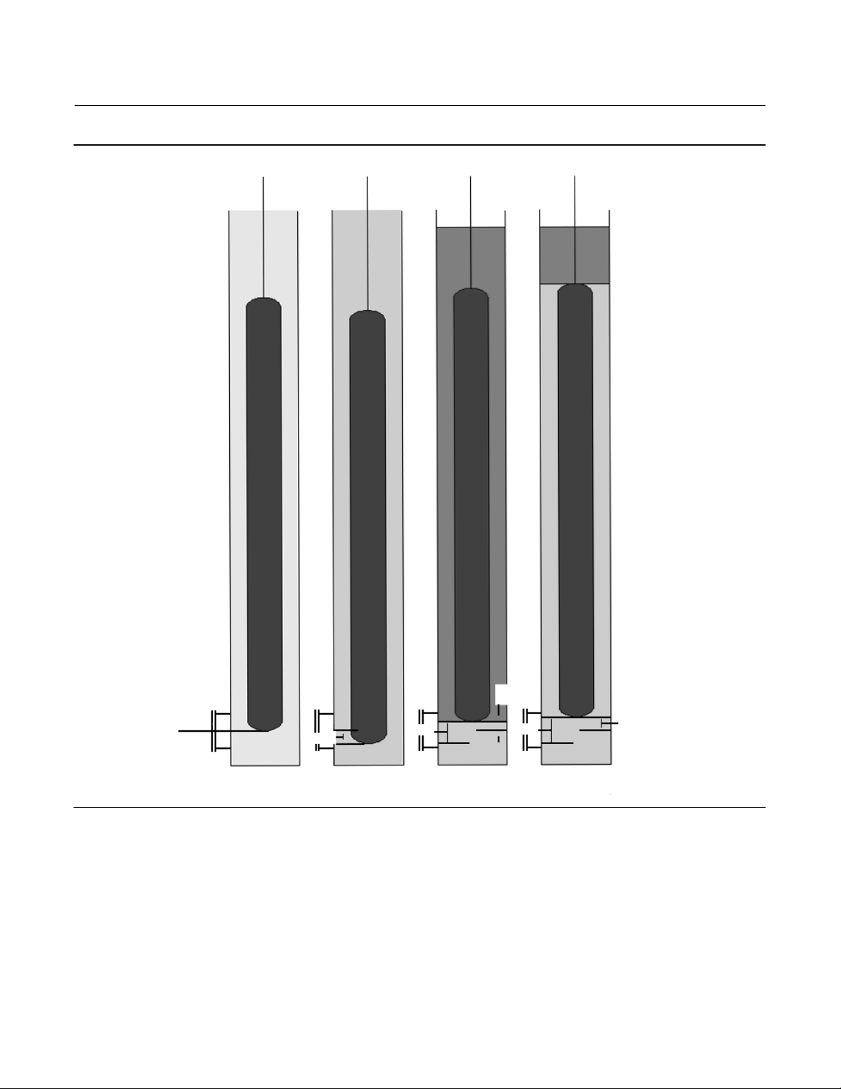
Figure 5. Illustration of Displacer Rise Effect
Instruction Manual Supplement
D103066X012
Initial
Offset
Ref
T = amb
F
= 0
b
Zero Shift
Y
B
T = proc
F
= 0
b
Rise
i
Y
B
T = proc
F
= f(SGU)
b
Rise
f
T = proc
F
Y
B
= f(SGL)
b
Y
B
Final Offset
6

Instruction Manual Supplement
D103066X012
249 Sensors
September 2017
Temperature‐Induced Zero‐Shift at Zero Buoyancy
If the physical zero reference was established at zero buoyancy and ambient temperature, there is an additional
zero‐shift to take into account. The zero buoyancy position of the bottom of the displacer at process temperature will
be lower, because of the reduction in torque rate.
(13)
*
W
RiseRate
ZeroShift
proc
D
=
G
Note that the combination of:
a. the location of the displacer bottom relative to the external reference at ambient,
b. the zero-shift at process temperature, and
c. the initial displacer rise at process temperature,
will determine the extent of any unobservable region between the external zero reference and the displacer bottom.
amb
norm
*
G
norm
-1.0
)
(
We must decide what our process variable (PV) calculation is going to use for a zero reference. Since any interface level
excursion below the bottom of the displacer cannot change the output, it is convenient to call the displacer bottom
“zero” for the test, and this has been standard procedure in pilot mounting. In the digital level controller, Level Offset
is used to adjust the digital output to zero at this condition.
Lowest Observable Cage Interface Level
If it is desired to line up the calculation with the physical external reference, the Level Offset (and range values) can be
adjusted according to the following.
(14)
H
cage0
ZeroShift
=
proc
L
Rise
)
0proc
D
Where:
H
cage0
= highest possible value of cage
interface level (normalized to
displacer length), relative to zero
buoyancy, ambient temperature
coupling point, when displacer
interface level is 0.0 (bottom of
displacer).
This is the physical interface level below which a change is unobservable. The range values or alarm values should be
set within the observable range of PV to make sure that over‐ and under‐flow conditions are reported to the control
system.
7

249 Sensors
September 2017
Instruction Manual Supplement
D103066X012
Weight Calculation Procedure
To compute the weight required, at room temperature, to simulate a given process‐condition cage interface level:
a. Start with an initial buoyancy based on the SG of the upper fluid,
b. subtract it from the displacer weight, and
c. correct the result for process temperature.
This will give the test weight for the lowest observable process condition.
W
-
F
D
W
net_test
J
=
i
G
Bmin
norm
The change in weight for a process‐temperature, cage (or vessel) interface level condition, one displacer length higher
than the above state, is given by:
(16)
(15)
ΔW
(
J
f
disp
=
cage
G
)
norm
ΔH
/
ΔH
proc
ΔF
*
(
)
B max
The net weight for the 100% cage process condition is:
(17)
W
net_test
W
J
=
f
net_test
J
i
−
ΔW
J
f
Other values of ΔW can be computed from:
(18)
ΔW
ΔH
=
cage
*
(
ΔH
disp
/
G
ΔH
norm
cage
)
proc
*
(ΔFB)
max
Where:
cage
cage0
=H
< H
ΔH
Valid for H
Remember that it is common to arbitrarily set H
cage
cage
− H
cage0
< [1/ (ΔH
disp
/ ΔH
cage)proc
]
to zero for test purposes when using weights. (For water column
cage0
calculations in the next section, it is more important to keep track of the initial process‐condition cage level to
simulate the initial buoyancy correctly.) The resultant net weights for the intermediate levels are given by:
(19)
J
-
W
net_test
W
=
net_test
ΔW
i
This assumes that the net weights do not violate the maximum or minimum load for the torque tube. Refer to table 5.
8

Instruction Manual Supplement
D103066X012
249 Sensors
September 2017
2. Water Column Method:
It is possible to simulate a range of buoyancy adjusted for process temperature effect by using a water column at room
temperature. At the ambient SG = 1.0 level application, the corrections should all cancel out, leaving H
PV.
Cage Water Level Required to Simulate Interface Levels
If we have computed an equivalent weight for a given process condition in section 1, the ambient temperature water
level on the displacer that will produce the same torque tube rotation is:
(20)
W
W
-
net
H
disp_eq
=
For high temperatures and high SG, the range of conditions that can be simulated will contract, since we are limited by
the actual displacer weight and the nominal density of water.
We must next convert this equivalent displacer level into an equivalent cage level using the inverse of the relationship
in equation 11, without the temperature compensation.
D
V
ρ
*
D
w
= desired
cage
(21)
)
*
ΔH
ΔH
disp
cage
amb
ρ
L
D
=
w
V
D
*
RiseRate
L
D
amb
The result is:
(22)
*
W
-
H
cage_eq
disp
ΔH
/
cage
ρ
w
amb
*
V
D
ΔH
()
=
W
(
D
net
)
Process Interface Level Simulated by a Given Cage Water Level
We can also write a generic equation for the process‐condition displacer interface level simulated by a given
room‐temperature displacer water level:
First, convert the ambient cage water level to an ambient displacer water level:
(23)
H
H
disp_eq
=
(
Next, define an intermediate variable to compute the apparent SG being simulated at process conditions by the
ambient displacer water level:
ΔH
cage
cage
/
ΔH
disp
)
amb
SGapp
sim
(24)
norm
*
)
1-
G
(
=
)
W
ρ
*
w
G
D
V
norm
D
*
H
disp_eq
9

249 Sensors
September 2017
Instruction Manual Supplement
D103066X012
Now use this apparent SG value to compute the simulated interface level on the displacer:
(25)
sim
SGL-SG
-SG
U
U
H
disp
sim
SGapp
=
Finally convert the simulated process‐conditions displacer interface level to simulated process‐condition cage
interface level, by the equation:
H
disp
H
cage
Where H
H
=
sim
is either 0.0 or the value computed in equation 14, per the practice being followed for PV reference.
cage0
cage0
)
ΔH
disp
()
sim
ΔH
/
cage
proc
3. Tables of Nominal Values
If the calibration is being run per standard practice the values of the parameters for the above equations are generally
available for observation in the instrument memory. For analog instruments, a table of nominal values may be
consulted to generate good approximations.
Table 1. Gnorm for Common Torque Tube Materials Above Room Temperature
Gnorm
(26)
Material
N05500 1 0.9923 0.9866 0.9808 0.9692 0.9577 0.9385 0.9192
N06600 1 0.9861 0.9759 0.9657 0.9529 0.9401 0.9256 0.9111
N10276 1 0.9802 0.9649 0.9497 0.9329 0.9161 0.9010 0.8859
S31600 1 0.9609 0.9378 0.9108 0.8837 0.8597 0.8277 0.7993
These values are approximations derived from various metal-alloy industry publications
Table 2. Gnorm for 316 SST Below Room Temperature
Material
S31600 1.0836 1.0807 1.0635 1.0179 1
Low temperature data for N05500, N06600, and N10276 not available at time of publication.
_C _F _C _F _C _F _C _F _C _F _C _F _C _F _C _F
21 70 93 200 149 300 204 400 260 500 316 600 371 700 427 800
Gnorm
_C _F _C _F _C _F _C _F _C _F
-240 -400 -184 -300 -129 -200 -18 0 21 70
Table 3 provides the theoretical unloaded rate, and the composite or effective torque rate measured by the digital
level controller at the end of the pilot shaft. The physical rotation at the far end of the torque tube may be a bit greater
than what these tables would predict, due to some wind‐up of the pilot shaft.
Table 3. Theoretical Room Temperature Torque Rates
Composite Rate
Family / Wall Material
249, 249B,
249BF 249BP, 259B,
249P (CL150-600),
249W
HEAVY
1. N05500 is the default material.
2. Appropriate for 2500 controllers only.
10
N05500
N06600 1P8662X0012 1.66 14.7 2.07 18.3 2.18 19.3
S31600 1K4541000A2 1.76 15.5 2.18 19.3 2.29 20.3
N10276 1K453140152 1.75 15.5 2.16 19.1 2.27 20.1
Torque Tube
Part Number
(1)
1K4497X0012 1.48 13.1 1.90 16.8 2.01 17.8
Unloaded Rate
Nwm/deg lbfwin/deg Nwm/deg lbfwin/deg Nwm/deg lbfwin/deg
(2)
-continued-
W/O Insulator W/Insulator

Instruction Manual Supplement
D103066X012
Table 3. Theoretical Room Temperature Torque Rates (continued)
Family / Wall Material
249,
249B, 249BF
249BP,
259B,
249P
(
CL150-600),
249C
249CP
249PT
249VT
249W
STANDARD
1. N05500 is the default material.
2. Appropriate for 2500 controllers only.
HEAVY
Family / Wall Material
249B
249,
249BP,
259B,
249P
(CL150-600),
249C
249CP
249PT
249VT
249W
THIN
1. N05500 is the default material.
2. Appropriate for 2500 controllers only.
STANDARD
Family / Wall Material
249K,
249L, 249N, 249VS,
249P (CL900‐2500),
STANDARD
1. N05500 is the default material.
2. Appropriate for 2500 controllers only.
Family / Wall Material
249K,
249L, 249N, 249VS,
249P (CL900‐2500)
THIN
1. N05500 is the default material.
2. Appropriate for 2500 controllers only.
Unloaded Rate
Nwm/deg lbfwin/deg Nwm/deg lbfwin/deg Nwm/deg lbfwin/deg
N05500
Torque Tube
Part Number
(1)
1K4493X0012 0.764 6.76 0.988 8.75 1.05 9.27
N06600 1K4515000A2 0.758 6.71 0.952 8.42 1.00 8.87
S31600 1K4503000A2 0.848 7.50 1.06 9.36 1.11 9.85
N10276 1K4527000A2 0.799 7.07 0.993 8.79 1.04 9.23
Unloaded Rate
Nwm/deg lbfwin/deg Nwm/deg lbfwin/deg Nwm/deg lbfwin/deg
N05500
Torque Tube
Part Number
(1)
1K4495X0012 0.384 3.40 0.502 4.44 0.532 4.70
N06600 1K4517000A2 0.405 3.58 0.513 4.54 0.540 4.78
S31600 1K4505000A2 0.416 3.68 0.524 4.64 0.551 4.87
N10276 1K4529X0012 0.427 3.78 0.535 4.73 0.562 4.97
Unloaded Rate
Nwm/deg lbfwin/deg Nwm/deg lbfwin/deg Nwm/deg lbfwin/deg
N05500
Torque Tube
Part Number
(1)
1K4499X0012 1.06 9.41 1.46 13.0 1.54 13.7
N06600 1K4519000A2 1.20 10.6 1.58 14.0 1.66 14.7
S31600 1K4507000A2 1.26 11.2 1.66 14.7 1.75 15.4
N10276 1K9159X0012 1.26 11.2 1.65 14.6 1.73 15.3
Unloaded Rate
Nwm/deg lbfwin/deg Nwm/deg lbfwin/deg Nwm/deg lbfwin/deg
N05500
Torque Tube
Part Number
(1)
1K4501X0012 0.550 4.87 0.762 6.74 0.804 7.12
N06600 1P747040042 0.546 4.83 0.729 6.45 0.765 6.77
S31600 1K450935072 0.611 5.40 0.809 7.16 0.848 7.51
(2)
(2)
(2)
(2)
249 Sensors
September 2017
Composite Rate
W/O Insulator W/Insulator
Composite Rate
W/O Insulator W/Insulator
Composite Rate
W/O Insulator W/Insulator
Composite Rate
W/O Insulator W/Insulator
11

249 Sensors
September 2017
Instruction Manual Supplement
D103066X012
Additional Information
Table 4. Moment Arm (Driver Rod) Length
Sensor Type
(2)
249 203 8.01
249B 203 8.01
249BF 203 8.01
249BP 203 8.01
249C 169 6.64
249CP 169 6.64
249K 267 10.5
249L 229 9.01
249N 267 10.5
249P
(CL125-600)
249P
(CL900-2500)
249VS (Special)
(1)
See serial card See serial card
249VS (Std) 343 13.5
249W 203 8.01
1. Moment arm (driver rod) length is the perpendicular distance between the vertical
centerline of the displacer and the horizontal centerline of the torque tube. See figure
6. If you cannot determine the driver rod length, contact your Emerson sales office
Local Business Partner and provide the serial number of the sensor.
2. This table applies to sensors with vertical displacers only. For sensor types not listed,
or sensors with horizontal displacers, contact your Emerson sales office for the driver
rod length. For other manufacturers' sensors, see the installation instructions for that
mounting.
Moment Arm
mm Inch
203 8.01
229 9.01
Table 5. Maximum Unbuoyed Displacer Weight
Sensor Type
249, 249B, 249BF,
249BP, 249W
249C, 249CP
249VS
249L, 249P
(1)
249K
1. High pressure CL900 through 2500.
Torque Tube Wall
Thickness
Thin
Standard
Heavy
Standard
Heavy
Thin
Standard
Thin
Standard
Thin
Standard
(1)
Displacer Weight,
W
(lb)
T
3.3
5.0
9.5
4.0
6.4
3.0
5.5
4.5
8.5
3.8
7.3
Figure 6. Method of Determining Moment Arm from
External Measurements
E0283
L
MOMENT
ARM
LENGTH
HORIZONTAL C
OF TORQUE TUBE
L
VERTICAL C
OF DISPLACER
Table 6. Related Documents
Document Part Number
249 Caged Displacer Sensors Instruction Manual D200099X012
249 Cageless Displacer Sensors Instruction Manual D200100X012
249VS Cageless Displacer Sensor Instruction Manual D103288X012
or
249W Cageless Wafer Style Level Sensor Instruction
Manual
2500 and 2503 Level Controllers and Transmitters
Instruction Manual
DLC3010 Digital Level Controller Quick Start Guide D103214X012
DLC3010 Digital Level Controller Instruction Manual D102748X012
2502 Level Controller D200126X012
These documents are available from your Emerson sales office or Local Business
Partner. Also visit our website at Fisher.com
.
D102803X012
D200124X012
Neither Emerson, Emerson Automation Solutions, nor any of their affiliated entities assumes responsibility for the selection, use or maintenance
of any product. Responsibility for proper selection, use, and maintenance of any product remains solely with the purchaser and end user.
Fisher and FIELDUVE are marks owned by one of the companies in the Emerson Automation Solutions business unit of Emerson Electric Co. Emerson
Automation Solutions, Emerson, and the Emerson logo are trademarks and service marks of Emerson Electric Co. All other marks are the property of their
respective owners.
The contents of this publication are presented for informational purposes only, and while every effort has been made to ensure their accuracy, they are not
to be construed as warranties or guarantees, express or implied, regarding the products or services described herein or their use or applicability. All sales are
governed by our terms and conditions, which are available upon request. We reserve the right to modify or improve the designs or specifications of such
products at any time without notice.
Emerson Automation Solutions
Marshalltown, Iowa 50158 USA
Sorocaba, 18087 Brazil
Cernay, 68700 France
Dubai, United Arab Emirates
Singapore 128461 Singapore
www.Fisher.com
12
E 2003, 2017 Fisher Controls International LLC. All rights reserved.
 Loading...