

Instruction Manual
MCK-1023
May 1980
Type N201
Type N201
Install, use, and maintain this equipment
according to Fisher instructions and all
federal, state, local laws and codes, and
NFPA Pamphlet 58. Periodic inspection and
maintenance is essential.
Introduction
Type N201 automatic cylinder filling valve is supplied
completely piped up, and consists of a filler valve assembly,
two Type 67 regulators with pressure gauges, a trip valve,
and special parts for alternate scale installations.
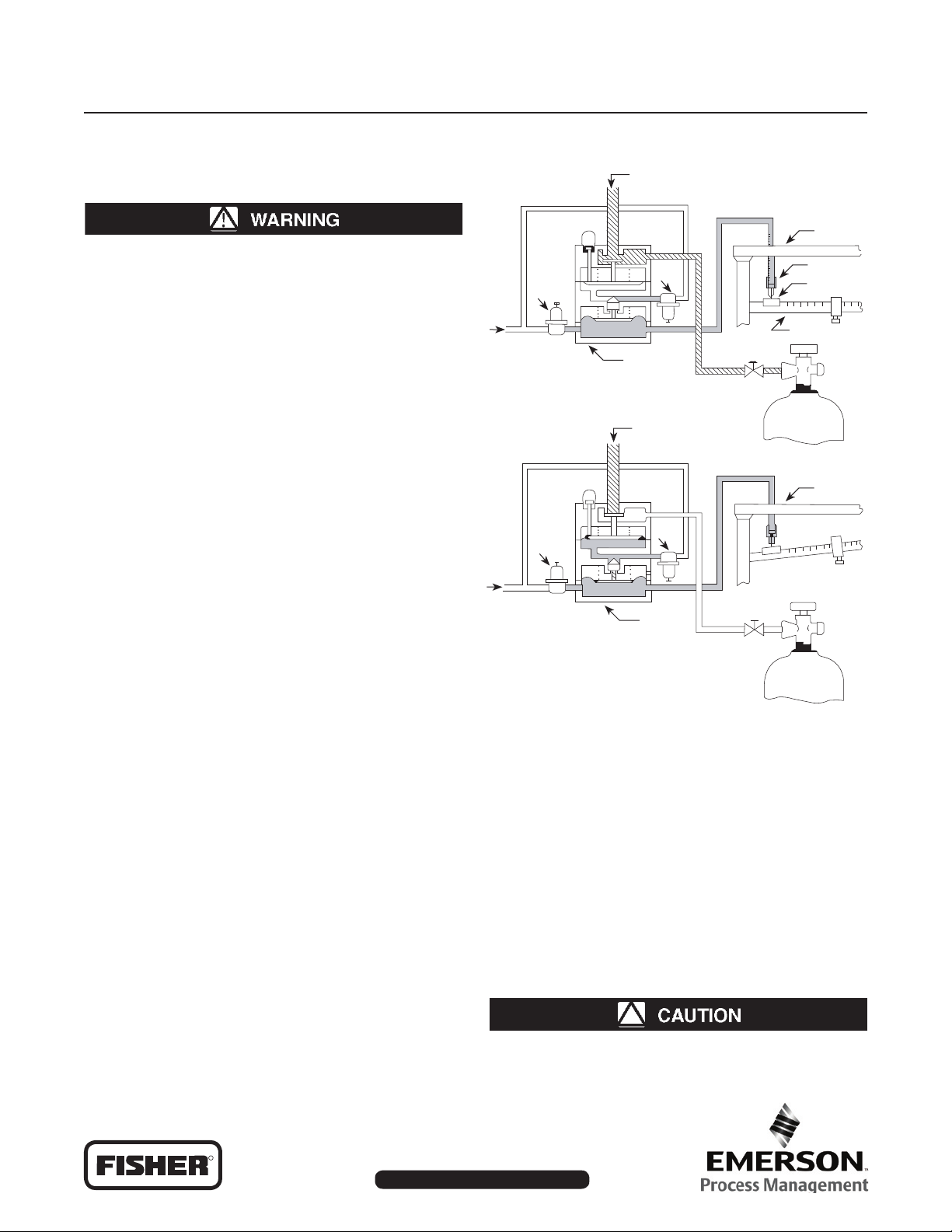
Principle of Operation
Refer to Figure 1. Supply pressure registers at
regulators 1 and 2. Pressure from regulator 1 registers
beneath the lower diaphragm of the filler valve, see “A”
in Figure 1. This pressure holds the lower valve closed,
preventing pressure from regulator 2 from registering on
the upper diaphragm. Spring force holds the upper valve
open, and liquid from the charging pump can enter the
cylinder to be filled.
When the cylinder reaches the predetermined weight set on
the scale, the beam button on the scale beam contacts the
trip valve, see “B” in Figure 1. The trip valve opens to exhaust
pressure from under the lower diaphragm. Spring force opens
the lower valve, allowing pressure from regulator 2 to register
on the upper diaphragm. This closes the upper valve, and
stops flow through the orifice. A red button indicates that the
filler valve is closed and that the cylinder is full. Removing the
full cylinder from the scale closes the trip valve and permits
the system to reset itself for the next cylinder.
Installation
Refer to Figure 2.
1. Connect the top 1/2-inch FNPT connection “C” of the
filler valve to the charging manifold.
2. Determine if the trip valve hose is long enough to reach
the scale frame as shown. If not, insert 1/8-inch pipe
as needed.
3. Standard trip valve installation (also see alternate
methods, 3.A and 3.B):
a. The trip valve should be installed at approximately 1/5
of the scale beam length, measured from the pivot point to
FROM CHARGING
PUMP
SCALE
FRAME
REG
# 1
SUPPLY
PRESSURE
A. FILLING CYLINDER
REG
# 1
SUPPLY
PRESSURE
B. FULL CYLINDER
REG
# 2
FILLER
VALVE
FROM CHARGING
PUMP
REG
# 2
FILLER
VALVE
TRIP VALVE
BEAM
BUTTON
SCALE BEAM
SCALE
FRAME
Figure 1. Operational Schematic
the beam stop, see drawing. Although the trip valve can
be installed to operate directly off the scale beam, it is not
recommended because of the side play in most scale beams
can resuIt in failure to contact the trip valve.
b. Drill a 5/8-inch (16 mm) hole through the scale frame
directly above the point on the scale beam, determined in
step 3 (a).
c. Remove locknut “D” and insert trip valve through the
5/8-inch (16 mm) hole. Replace locknut.
d. Place beam button “J” on the scale beam directly
beneath the trip valve.
e. Using locknuts “D” and “E”, position trip valve stem “B”
so that it barely contacts beam button “J” with the scale
beam in a level position, see drawing.
Be certain that the beam button cannot
contact the trip valve housing at point “A”
when the scale beam is in the uppemost
D450003T012
R
www.FISHERregulators.com/lp
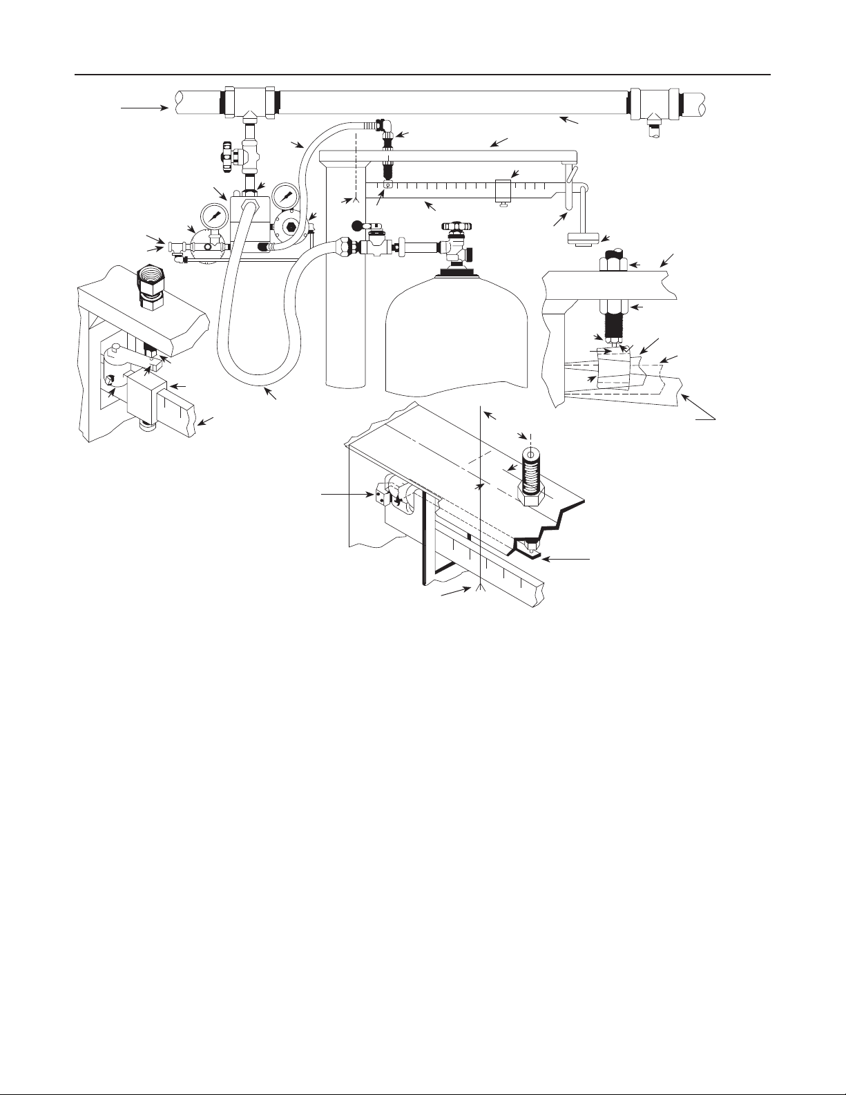
Type N201
FROM CHARGING PUMP
PILOT VAPOR
PRESSURE FROM
AIR COMPRESSOR
STORAGE TANK,
OR AUXILIARY
PROPANE CYLINDER
P
K
J
ALTERNATIVE TRIP VALVE
INSTALLATION #1
TYPE 201
FILLER VALVE
I
TRIP VALVE
H
SCALE BEAM
TRIP VALVE
HOSE
C
FILLING HOSE
APPROX. 1/5
LENGTH OF
SCALE BEAM
TRIP VALVE
PIVOT
2
POINT
M
J
SCALE BEAM
1 1/4
(31,8)
SCALE FRAME
H
BEAM STOP
3
(76,2)
MANIFOLD
STANDARD TRIP VALVE
INSTALLATION
F
TRIP
VALVE
B
J
BEAM WHEN CYLINDER
IS NOT FILLED
SCALE
FRAME
E
D
BEAM IN RAISED
POSITION
A
BEAM
HORIZONTAL
(LEVEL)
Figure 2. N201 Installation
position (full cylinder). To correct this, try
raising the trip valve slightly and retighten
locknuts “D” and “E”. If raising the trip valve
does not correct the situation the 5/8-inch
(16 mm) hole on the scale frame will have to
be drilled closer to the pivot point.
3.A On installations where the slide weight “H” must be
moved to zero, alternate trip valve installation no. 1 can be
made. (This is usually necessary when both 20 pounds
(9 kg) and 100 pounds (45,4 kg) cylinders are to be filled.)
Follow steps 3 (a), (b), (c) and:
d. Place the beam button “J” on the scale beam close
enough to the pivot point to allow the slide weight to move to
zero, see drawing. If there is not enough room to permit this,
either the beam button must be ground down or the user
must make a special beam button.
e. Mount beam bar “K” on the beam button so that it extends
directly under the trip valve. The beam bar can be bent if
necessary and extra length can be cut off.
f. Make certain the beam barely contacts the trip valve
stem when the scale beam is in a level position.
L
INCH
(mm)
PIVOT
POINT
ALTERNATE TRIP VALVE INSTALLATION # 2
(FOR TYPE 1124A AND 1280A FAIRBANKS MORSE SCALE)
3.B For Fairbanks Morse Type 1124A and 1280A scales,
alternate trip valve installation no. 2 must be made, see drawing.
a. Measure 3-inch (76,2 mm) from the pivot point as shown.
b. Measure 1 1/4-inch (31,75mm) from the scale frame
center line toward the back of the scale.
c. Drill a 5/8-inch (16 mm) hole through the scale frame
at this point.
d. Attach the beam bar “L” to the clamp “M” with two
screws, and attach the clamp to the rear of the scale beam
with two screws.
e. Remove locknut “D” and insert the trip valve through the
5/8-inch (16 mm) hole. Replace locknut.
f. Using locknut “D” and “E”, position trip valve so that
it barely contacts the beam bar ”L” with the scale in a
level position.
4. Connect supply pressure (air or gas) at point “P”.
Recommended supply pressure is at least 30 psig (2,1 bar),
since regulator 2 is set at 30 psig (2,1 bar) outlet pressure.
A 30 psig (2,1 bar) supply is sufficient for pump discharge
pressures up to 350 psig (24,1 bar). Regulator 1 is set at
3 psig (0,21 bar).
2

Type N201
Note
If propane vapor pressure is used, atmospheric
or room temperature below 8°F (-13,3°C) will
limit supply pressure to below 30 psig (2,1 bar).
To assure tight shutoff of the filler valve in this
event, refer to the table below.
MINIMUM SUPPLY
PRESSURE, PSIG (bar)
21 (1,4) 200 (13,8)
19 (1,3) 150 (10,3)
17 (1,2) 100 (6,9)
14 (0,97) 50 (3,4)
13 (0,90) 25 (1,7)
5. Attach the propane filling hose to one of the filler valve
outlets. Plug the other outlet. The filling hose must be
complete with a shutoff valve and suitable cylinder valve
connection. The filling hose and shutoff valve can be
counterbalanced for easy handling if desired.
PUMP DISCHARGE, PSIG (bar)
MAXIMUM RECOMMENDED
Operation
1. Place cylinder on scale platform and connect filler hose.
2. Slide beam weight “H” to tare weight stamped on cylinder.
3. Balance scales to compensate for the weight added by
the filler hose and shutoff valve. On some scales this can be
done by means of a small weight near the beam pivot pin. On
others a suitable weight can be added to scale pan “F”.
4. Add a 100 pounds (45,4 kg) weight (or the net weight
desired) to scale pan “F”, and open the cylinder and hose
valve for trial automatic filling operation.
5. Proceed with filling operation until scale beam rises and
contacts the trip valve stem. The filler valve will close and
the filling operation is complete. This is indicated by the red
button on top of the filler valve. Close the hose shutoff valve
and the cylinder valve.
6. Check weight of full cylinder on another
weight or the weight in scale pan “F” may have to be
readjusted slightly until the correct cylinder weight is
obtained. Filling accuracy is largely dependent upon the
condition of the scale used with Type N201.
7. After the scales have been checked and adjusted, simply
position the empty cylinder on the scale, connect the filling
hose, slide beam weight “H” to the tare weight stamped on
the cylinder, open the hose shutoff valve and the cylinder
valve, and the N201 will fill the cylinder to the weight added
on the scale pan.
Note
When operating with high pump pressure,
the filler valve may close off, then reopen
for a short spurt and close off again. This
is due to the force of
stream. If the proper cylinder weight has
been obtained before the additional spurt,
the incoming liquid
scale. Balance
the operator should immediately close the
hose shutoff valve when the scale beam
contacts the trip valve stem. If the scales
are balanced after the additional spurt, the
operator should wait for this before closing
the hose shutoff valve.
In Case of Trouble
1. If sticking of the main (upper) valve should occur, place a
few drops of oil below the disc holder, Key No.5 in Figure 3.
This can be done with an eye dropper or oil can through one
of the outlet ports. Refer to the disassembly instructions if this
does not correct the situation.
2. If the disc holder wears out quickly, check the outlet
pressure of regulator no. 2. Too high a regulator setting will
cause the disc to fail. Refer to step 4 under “Installation”.
3. If the trip valve stem “B” should stick, remove the lower
trip valve body, and clean out all oil or grease. Polish the
seat in the trip valve body by rotating the eraser end of a
pencil against the seat 10 or 12 times.
Disassembly
To check disc holder assembly, O-ring, and diaphragms
proceed as follows (numbers in parenthesis refer to Key Nos.
in Figure 3):
1. Remove tubing connection from the angle adaptor in
Type 67/683 (key 30).
2. Mark the valve body (key 17), valve housing (key 2),
and valve head (key 1) so that they can be aligned easily
when reassembling.
3. Remove cap screws (key 22).
4. Separate the valve head (key 1), valve housing (key 2), and
valve body (key 17). Examine the upper and lower diaphragms
(keys 10 and 32). Replace if necessary.
5. Remove orifice (key 3) and unscrew the disc holder
assembly (key 5). Examine and replace if necessary.
6. Remove bushing (key 8) and take out the O-ring (key 7).
Examine and replace if necessary. Put Dow Corning #3 grease
(or equivalent) on the O-ring.
7. Make sure all parts are clean before reassembling.
To reassemble
1. Replace orifice (key 3) in valve head (key 1).
2. Replace O-ring (key 7) and screw in bushing (key 8).
3. Replace disc holder assembly (key 5) and
spring (key 21). Screw the disc holder into the diaphragm
head (key 9).
4. Replace upper diaphragm (key 10) on the valve head
(key 1). Align the valve housing (key 2), spring (key 35),
lower diaphragm assembly (key 32), and valve body (key 17)
so that the cap screws (key 22) can be inserted.
5. Connect tubing (key 39) to angle adaptor in
(key 30).
Type 67/683
3

Type N201
34
39 30 15 9 20 5 7 8 21 13 31 38 40
33 11 10 18 19 3 6 1 45 2
46
47
44
36
42
17 16 32
22 26 14 35
23 24
25 37
43 41
BUTTON AND BAR FOR
ATTACHMENT TO SCALE BEAM
Figure 3. Type N201
Parts List
Key Description
1 Valve Head
2 Valve Housing
3 Orifice
5* Disc Holder Assembly
6 Control Valve Stem
7* O-Ring
8 Bushing
9 Diaphragm Head
10* Upper Diaphragm
11 Bushing
13 Pilot Valve
14 O-Ring Washer
15* O-Ring
16 Pilot Valve Stem
17 Valve Body
18 Indicator Rod
19 Sight Glass
20 Indicator Cap
21 Control Valve Spring
22 Cap Screw (6 required)
23 Trip Valve Stem
* Recommended spare parts for stock.
Fisher and Fisher Regulators are marks owned by Fisher Controls International, LLC. The Emerson logo is a trademark and service mark of Emerson Electric Co. All other marks are the
property of their respective owners.
The contents of this publication are presented for informational purposes only, and while every effort has been made to ensure their accuracy, they are not to be construed as warranties or guarantees, express
or implied, regarding the products or services described herein or their use or applicability. We reserve the right to modify or improve the designs or specifications of such products at any time
without notice.
Fisher does not assume responsibility for the selection, use or maintenance of any product. Responsibility for proper selection, use and maintenance of any Fisher product remains solely with
the purchaser.
Emerson Process Management
Key Description
24 Trip Valve
25 Inner Valve
26 Screen Holder Assembly (2 required)
30 Type 67/683
31 Type 67/685
32* Diaphragm Assembly
33 Pipe Nipple (3 required)
34 Tee
35 Spring
36 Inverted Flare Elbow (2 required)
37 Nut (2 required)
38 Hose Assembly
39 Tubing Assembly
40 Street Elbow
41 Beam Button
42 Beam Bar
43 Set Screw
44 Machine Screw
45 Vent Screen (2 required)
46 Trip Valve Spring
47 Spring Set
ed
Fisher Controls International, LLC.
P.O. Box 8004
McKinney, Texas 75070, USA
Telephone: 1 (800) 588-5853
Telephone: 1 (469) 293-4201
©Fis her Controls Inte rnation al, LLC., 1980; All Rights Rese rved
www.FISHERregulators.com/lp
 Loading...