

Page 1
P K-411UD
Windows®-Based
Off-Line Programming Utility
Software Manual
For the Fire•Watch 411UD and 411UDAC
D igital Alarm C o mmunicator Tra n smitte rs
Windows is a Registered Trademark of Microsoft Corporation.
One Fire•Lite Place
Northford, CT 06472
Phone (203) 484-7161
F AX: (203) 484-7118
Document #50802
1/5/99 Rev.
P/N 50802:B ECN 98-487
© 1999
B
Page 2

Installa tion P re cautions
WARN ING - S ev eral diff erent sources of power can
be connected to the fire alarm control panel.
Disconnect all sources of power before servicing.
Control unit and associated equipment may be
damaged by removing and/or i nserting cards, modules or inte rconnect ing ca bles w hile t he un it is e nergized. Do not attempt to inst all, service or operate
this unit until this manual is read and understood.
CAUTION - Sy stem Reacceptance Test after Soft-
ware Changes: To ensure proper system operation,
this product must be tested in accordance with NFPA
72 Chapter 7 after any programming operation or
change in site-specific software. Reacceptance testing is required a fter any c hange, additi on or del etion
of system components or after any modification,
repair or adjustment to system ha rd ware or wir ing.
All components, circuits, system operations or
software functions known to be affected by a change
must be 100% tested. In addition, to ensure that
other operations are not inadvertently affected, at
least 10% of initiating devices that are not directly
affected by the change, up to a maximum of 50
devices, must be tested and proper syst em operation
verifie d.
This system meets NFPA requirements for operation
o
at 0 - 49
(noncondensing) @ 3 0
of the system's standby batteries and the electronic
components may be adversely affected by extreme
temperature ranges and humidity. Therefore, it is
recommended tha t this system and its peri pherals be
installed in an environment with a nominal room
temperature of 60 - 80
Ve rify that wire sizes are adequate for all initiating
and indicating device loops. Most devices cannot
tolerate more than a 10% I.R. drop fr o m the specified
device voltage.
C and at a relative humidity o f 85% RH
o
C. However, the useful life
o
F.
Fi re Alarm System Limitations
An auto matic fire a larm sys tem - typically made
up of smoke detectors, heat de tectors, manual pull
stations, audible warning devices and a fire alarm
control with remote not ification capability, can provide early warning of a developing fire. Such a
system, however, does not assure protection against
property damage or loss of life resu lti ng from a fire.
Any fire alarm system may fail for a variety of
reasons:
Smoke detectors may not sense fire where
smoke cannot reach the detectors such as in
chimneys, in walls, in roo fs, or on the other side
of closed doors. Smoke detect ors also may not
sense a fire on another level or floor of a building.
A second floor detector, for example, may not
sense a first floor or basement fire. Fur therm ore,
all types of smoke de tectors, both ionization an d
photoelectric types, have sensing limita tions. No
type of smoke detector can sen se every kind of
fire caused by carelessness and safety hazards
like smoking in bed, violent explosions, escaping
gas, improper storage of flammable materials,
overloaded electrical circuits, children playing
with matches or arson.
IMPORTANT! Smoke detectors must be
installed in the same room as the control panel
and in room s used by the sy stem f or the connection of alarm transmission w iring, com munications, signaling and/or po wer. If detectors are not
so located, a developing fire may damage the
alarm system, cripp ling its ability to report a fire.
Adherence to the following will aid in problem-free
installation with long-term reliability:
While insta lling a fire a la rm system may make lower insura nc e
rates possible, it is not a substitute for fire insura nce
Like all solid state electronic devices, this
system may operate erratical ly or c an be da maged
when subjected to lightning induced transients.
Although no system is comple tely immune from
lightning transients and interferences, proper
grounding will reduce susceptibility. Overhead or
outside aerial w iring is not recomm ended, du e to
an increased susceptibility to nearby lightning
strikes. Consult with the Technical Services
Department if any problems are anticipated or
encountered.
Disconnect AC power and batteries prior to
removing or inserting circuit boards. Failure to do
so can damage circuits.
Remove all electronic assemblies prior to any
drilling, filing, reaming or punching of the
enclosure. When possible, make all cable entries
from the sides or rear. Before making modifications, verify that they will not interfere with
battery, transformer and printed circuit board
location.
Do not ti ghte n sc rew terminal s mo re than 9 inlbs. Over tightening may damage threads,
resulting in reduced terminal contact pressure and
difficulty with screw terminal removal.
This system contains static-sensitive
components. Always ground yourself with a
proper wrist strap before handl ing any circuits so
that static charges are removed from the body.
Use static suppressive packaging to protect
electronic assemblies removed from the unit.
Follow the instructions in the installation,
operating and programming manuals. These
instructions must be followed to avoid dama ge to
the control panel and associated equipment.
FACP operation and reliability depend upon
proper installation.
A udible warni ng de vic es such as bells m ay
not alert people if these devices are located on
the other side of closed or partly open doors or
are located on another floor of a building.
A fire alarm system will not operate without
any electrical power. If AC power fails, the
system will operate from standby batteries
only for a specified time.
Rate-of-Rise heat de tectors may be subject
to reduced sensitivity over time. For this
reason, the rate-of-rise feature of each detector
should be tested at least onc e per yea r by a
qualified fire protection specia list.
Equipment used in the system may not be
technically compatible with the control panel.
It is essential to use only equ ipment listed for
service with your control panel.
Telephone lines needed to transmit alarm
signals from a pr emis e to a central m onitoring
station may be out of servi ce or temporarily
disabled.
The most common cause of fire alarm
malfunctions, however, is inadequate maintenance. All devices and system wiring should be
tested and maintain ed by professional fire alarm
installers following written procedures supplied
with each device. System inspection and testing
should be scheduled monthly or as required by
National and/or local fire codes. Adequate written
records of all inspections sh ould be kept
Page 3

Tab le of Contents
CHAPTER 1: Product Description ..............................................................................................................6
1.1: Main Features..............................................................................................................................................6
CHAPTER 2: Getting Started.....................................................................................................................8
2.1: Basic System Requirements.......................................................................................................................9
2.1.1: System Microprocessor....................................................................................................................9
2.1.2: Memory and Drive Requirements....................................................................................................9
2.1.3: Monitor............................................................................................... ..... ...... ...................................9
2.1.4: Mouse...... ...... ...... ...................................................................................................................... ...... .9
®
2.1.5: Microsoft
2.2: About Modems............................................................................................................................................10
2.2.1: Compatible Modems............................. ............................................................................................10
2.3: Cable Connections.......................................................................................................................................11
2.4: Inventory......................................................................................................................................................11
FIGURE 2-1: Windows
2.5: Loading Software........................................................................................................................................11
2.5.1: Using W indows
FIGURE 2-2: Windows
FIGURE 2-3: Windows
2.5.2: PK-411UD Installation Prompts.......................................................................................................12
FIGURE 2-4: Installation to Hard Drive..............................................................................................12
FIGURE 2-5: Installation Path................................................... ...... ....................................................12
FIGURE 2-6: Installation Completed.............................................. ...... ..............................................13
2.6: Program Files ..............................................................................................................................................13
Windows® Environment................................................................................................9
®
3.1 Dialog Box............................................................................................11
®
To Load PK-411UD..............................................................................................11
®
95 Start........................................................................................................11
®
95 Dialog Box.............................................................................................12
CHAPTER 3: User Interface.......................................................................................................................14
FIGURE 3-1: PK-411UD ICON............................................................ ..............................................14
FIGURE 3-2: Copyright Window.................................................... ....................................................14
3.1: Initial Use of PK-411UD.............................................................................................................................14
FIGURE 3-3: Initialization Window............................... ........................................................ ...... . ..... .14
3.1.1: Log-in as Master...............................................................................................................................15
FIGURE 3-4: Log-in.......... ..................................................................................................................15
FIGURE 3-5: Communicator Selection Window................................................................................15
CHAPTER 4: Setup....................................................................................................................................16
4.1: Operator.......................................................................................................................................................16
FIGURE 4-1: Main Menu - Operator Setup........................................................................................16
FIGURE 4-2: Operator Information .............. ...... ..... ...........................................................................17
FIGURE 4-3: New Access.......................................................................... ...... ..... ..............................18
4.2: Default Directory and File...........................................................................................................................18
FIGURE 4-4: Main Menu - Configure Directories and Files..............................................................18
FIGURE 4-5: Default Selections ........ ..... ...... ......................................................................................19
4.2.1: Default Directory ................. .............................................................................................................19
FIGURE 4-6: Path Locator..................................................................................................................19
4.2.2: Install Directory ........ ...... ..... .............................................................................................................19
4.2.3: User Default Files ...................... .......................................................................................................20
FIGURE 4-7: User Default Files .........................................................................................................20
4.3: Modem ........................................................................................................................................................21
FIGURE 4-8: Main Menu - Configure Modem...................................................................................21
FIGURE 4-9: Configure Modem.........................................................................................................21
4.3.1: Modem........................................................ ...... ................................................................................22
FIGURE 4-10: Modem Selection ........................ ..... ...........................................................................22
4.3.2: Initialization String ............................... ............................................................................................22
Document 50802 Rev. B 1/5/99 P/N: 50802:B
3
Page 4

Table of Contents
FIGURE 4-11: Initialization String......................................................................................................22
4.3.3: Hangup String ...................................................................................................................................23
4.3.4: Communication Port .........................................................................................................................23
FIGURE 4-12: No Modem Found Window........................................................................................23
4.3.5: Modem Initialization and Testing......................................................................................................23
4.3.6: Saving Modem Settings.....................................................................................................................23
CHAPTER 5: Data Entry.............................................................................................................................24
FIGURE 5-1: Main Menu....................................................................................................................24
5.1: Customer......................................................................................................................................................25
FIGURE 5-2: Customer Files...............................................................................................................25
5.1.1: Adding Customer to Database...........................................................................................................25
FIGURE 5-3: Add Customer Button....................................................................................................25
FIGURE 5-4: Customer Entry window................................................................................................26
5.1.2: Add Customer Site Information to Database....................................................................................27
FIGURE 5-5: Customer Site Information............................................................................................27
5.1.3: Add Program File to Database..........................................................................................................27
FIGURE 5-6: Filename........................................................................................................................27
FIGURE 5-7: Existing File Selection ..................................................................................................28
FIGURE 5-8: New File........................................................................................................................28
FIGURE 5-9: Customer Files Window - Central Station ....................................................................29
5.1.4: Print Options .....................................................................................................................................29
FIGURE 5-10: Printing Options Window - Print All..........................................................................29
FIGURE 5-11: Print Current................................................................................................................30
FIGURE 5-12: Print Text.....................................................................................................................30
5.1.5: Customizing Program Files...............................................................................................................31
FIGURE 5-13: Central Station Programming.......................................................... ..... ...... .................31
FIGURE 5-14: Communications Format.............................................................................................32
FIGURE 5-15: Test Time Interval.......................................................................................................32
FIGURE 5-16: Backup Reporting........................................................................................................33
FIGURE 5-17: Communicator Disable /Trouble Call Limit Options..................................................33
FIGURE 5-18: 411UD Customer Files Window.................................................................................33
FIGURE 5-19: 411UD Input/Output Window.....................................................................................34
FIGURE 5-20: 411UD Input Function Selection.................................................................................34
FIGURE 5-21: 411UD Output Relay Programming............................................................................35
FIGURE 5-22: 411UD Option Programming......................................................................................35
FIGURE 5-23: 411UDAC Customer Files Window ...........................................................................36
FIGURE 5-24: Input/Output Window for the 411UDAC....................................................................36
FIGURE 5-25: 411UDAC Channel 1 - Input/output Window ............................................................37
FIGURE 5-26: 411UDAC Output Relay Options ...............................................................................37
FIGURE 5-27: AC Loss Delay Timer Options for the 411UDAC.....................................................38
FIGURE 5-28: 411UDAC Auto Silence Options................................................................................38
FIGURE 5-29: 411UDAC NAC Coding.............................................................................................39
FIGURE 5-30: 411UDAC Restoral Method Option............................................................................39
FIGURE 5-31: Customer Files Window - Event Codes......................................................................40
FIGURE 5-32: Event Code Programming...........................................................................................40
FIGURE 5-33: Customer Files Window - Service Terminal...............................................................41
FIGURE 5-34: Service Terminal Programming..................................................................................41
5.1.6: Automatic Download List.................................................................................................................43
FIGURE 5-35: Automatic Download ..................................................................................................43
FIGURE 5-36: Main Menu - Automatic Download............................................................................44
5.2: Modified Fields............................................................................................................................................44
FIGURE 5-37: 411UD Modified Fields ..............................................................................................44
FIGURE 5-38: 411UDAC Modified Fields.........................................................................................45
4
Document #50802 Rev. B 1/5/99 P/N: 50802:B
Page 5

Table of Contents
CHAPTER 6: Communications...................................................................................................................46
6.1: Download to Communicator.......................................................................................................................46
FIGURE 6-1: Downloading.................................................................................................................46
FIGURE 6-2: Download Connection Status........................................................................................46
6.1.1: Download with Callback Enabled.....................................................................................................47
6.1.2: Download with Callback Disabled....................................................................................................47
6.2: Upload from Communicator.......................................................................................................................48
FIGURE 6-3: Uploading......................................................................................................................48
FIGURE 6-4: Upload Connection Status.............................................................................................48
FIGURE 6-5: Upload Filename...........................................................................................................49
6.2.1: Conv erting an Upload File to a Download File ................................................................................49
FIGURE 6-6: Customer Window - Recall File....................................................................................49
FIGURE 6-7: Customer Site Information............................................................................................50
FIGURE 6-8: Filename Selection........................................................................................................50
FIGURE 6-9: Current Information Selection.......................................................................................51
FIGURE 6-10: Customer Window - Recall File..................................................................................51
6.3: Communicator Time.................. ..... .............................................................................................................52
FIGURE 6-11: Communicator Time...................................................................................................52
6.4: Troubleshoot................................................................................................................................................52
FIGURE 6-12: Troubleshoot Window for the 411UD ........................................................................52
FIGURE 6-13: Troubleshoot Window for the 411UDAC...................................................................53
6.5: Automatic Download ................ ..... .............................................................................................................53
FIGURE 6-14: Automatic Download Window for the 411UD ...........................................................54
FIGURE 6-15: Automatic Download Window for the 411UDAC......................................................54
FIGURE 6-16: View Log.....................................................................................................................55
CHAPTER 7: Secret Code..........................................................................................................................56
FIGURE 7-1: Secret Code...................................................................................................................56
CHAPTER 8: Utilities - Compare ................................................................................................................57
FIGURE 8-1: Compare........................................................................................................................ 57
FIGURE 8-2: Compare File Selections ...............................................................................................58
FIGURE 8-3: View Comparison..........................................................................................................58
8.1: Quick View of Differences ..........................................................................................................................59
FIGURE 8-4: Quick View Compare....................................................................................................59
8.2: Detailed Vie w of Dif fer ences............... .......................................................................................................60
FIGURE 8-5: Detailed View of Compare............................................................................................60
CHAPTER 9: Security Features..................................................................................................................61
9.1: Secret Code ......................... ....................................................................................................................... .61
FIGURE 9-1: Secret Code...................................................................................................................61
FIGURE 9-2: Downloading Secret Code.............................................................................................61
9.2: Panel Callback.......... ...... ...................................................................................................................... .......62
9.3: Digital Communicator Time-out.................................................................................................................62
9.4: Error Checking..................................... ...... ..... .................................................................... ........................63
9.5: Central Station Acknowledge......................................................................................................................63
9.6: Password Protection....................................................................................................................................63
Document 50802 Rev. B 1/5/99 P/N: 50802:B
5
Page 6
Product D escription
CHAPTER 1
The PK-411UD Off-Line Programming Utility
is a versatile utility program which allows
remote programming and communicator
interrogation of the Fire•Watch 411UD/
411UDAC over standard public telephone
lines. Using this utility, the communicator can
be programmed via modem using most IBM AT
or compatible computers, including laptops,
equipped with a Hayes
Program files can be created and stored on the
PC and then downloaded to the communicator.
Use of the PK-411UD software requires a full
understanding of the 411UD/411UDAC Digital
Communicator functionality prior to an y upload
or download activity. For information on the
digital communicator, refer to the Fire•Watch
411UD, manual P/N: 50759, or Fire•Watch
411UDAC, manual P/N: 51073. Each time a
new program is created or an existing program
is modified and entered into a 411UD/
411UDAC Digital Communicator, the communicator must be thoroughly tested.
P roduct Descr iption
®
compatible modem.
1.1 Main Features
• Program runs under Microsoft®
Windows
Windows
• Password protect i on with fou r separat e
authority levels
• Modem option selection window
• Operator Identification Utility provides
operator information wh ich is st ored in a
database
• Customer File Utility allows customer
configuration using separate data files
for each customer
• Download file utility (Download to
Communicator) permits versatile
program setup for programming digital
communicators. Create and customize a
master default download program or edit
existing programs
®
3.1 or higher, including
®
95
6
Document #50802 Rev.B 1/5/99 P/N 50802:B
Page 7

Main Features
• Upload file utility (Upload from Communicator) permits versatile examination of retrieved communicator
• Security Features:
• File Compare utility allows location by location comparison of separate upload and download files
• Print utility allows printing of upload and download file information
• On-line Help feature
• Escape (Esc) key feature which allows the recall of the last saved item in a program field
programs and information:
✓ Panel program
✓ Troubleshoot data and voltages
✓ Current communicator time
✓ Secret Code
✓ Time-out at communicator
✓ Callback (with Disable option)
✓ Panel Identification Number
✓ Error checking (with retry on error)
✓ Central Station acknowledge
Document #50802 Rev. B 1/5/99 P/N 50802:B
7
Page 8
Getting Started
CHAPTER 2
The PK-411UD software provides a
conv enient and po werful t ool which can be
used to program and manipulate the
411UD/411UD AC programm ing data from
a PC or laptop. This user friendly utility
has been designed to provide many features which will enhance the communicator's programmability. In order to take full
advantage of the available features, it is
important to become familiar with the
PK-411UD functions and the environment
in which the program was designed to
operate. This chapter pro vides information
on the minimum system requirements for
the computer in which the PK-411UD will
be installed.
Some computer literacy and a rudimentary
understanding of DOS and Windows
necessary to successfully use this utility.
Even if exposure to computers is limited,
the information in this chapter along with
DOS and Windows
should provide sufficient knowledge to use
the PK-411UD program. Take the time to
read and understand the installation as
presented in this chapter.
®
reference material
Getting Sta rted
®
are
An On-line Help feature has been
incorporated into the software. For
information about a window option, use
the mouse arrow to point to the window
option button or te xt block. Cl ick and hol d
the mouse button, and move the arrow off
the selected window button or block.
Release the mouse button and then press
the F1 keyboard key to dis play the Help
window for the selected option.
The keyboard Escape (Esc) key can be
used to recall the last saved item in a
program field. This can be particularly
useful if, while typing an entry into a
program field, the programmer decides to
delete the new entry before saving it.
Pressing the Escape (Esc) key will cause
the last saved entry to be displayed in the
program field in place of the recently typed
but not saved entry.
8
Document #50802 Rev.B 1/5/99 P/N 50802:B
Page 9

Basic System R equireme n ts
2 . 1 Ba sic Syste m Re quire ments
The PK-411UD Program has been designed for a
specific computer en viro nment. Although most IBM AT
or compatible computers will accommodate the
PK-411UD software, specific computer requirements
and operating systems must be adhered to. In order to
ensure proper operation of the PK-411UD software, the
minimum requirements listed below must be met.
2.1.1 System Microprocessor
Most IBM AT or compatible computers with at least a
486-66MHz microprocessor may serve as a service
terminal and will accommodate the PK-411UD
software.
2.1.2 Memory and Drive Requirements
The service terminal must have a minimum of 4 megabytes of onboard RAM in order to run the PK-411UD
software. The program must be run from a hard drive
and requires a minimum of 4 megabytes of hard drive
space to store the program.
2.1.3 Monitor
A minimum of a VGA monitor is required for adequate
display of the PK-411UD menu screens.
2.1.4 Mouse
Any IBM compatible mouse or track ball should be us ed
to run the program. The program may also be run from a
standard 101-key keyboard, although certain features
will not be accessible.
2.1.5 Microsoft® Wind ow s® Envi ro nme nt
The PK-411UD software was developed to run in a
Windows
3.1 or higher or Windows
To take full advantage of the Windows
a basic understanding of Windows
be acquired from t he many excellent books and manual s
on Microsoft
manual to provide this training, however, some of the
terms used in reference to Windows
this section.
Document #50802 Rev. B 1/5/99 P/N 50802:B
®
environment. Microsoft® Windows® version
®
Windows®. It is not the intention of this
®
95 must be installed.
®
-based software,
®
is needed and may
®
are indicated in
9
Page 10

About Mode ms
2 . 2 About M ode ms
A modem (modulator/demodulator) conve rts the digital data signals of a computer to audio tones in order to transmit
the serial data over standard telephone lines. The modem also converts the incoming audio tones to digital data that
the computer can use.
Two basic types of modem have been designed for IBM PCs and compatibles:
• direct connect internal modems
• direct connect external modems
The internal modem is designed as an IBM P C compati ble e xpan sion card wh ich plugs i nto the comput er's e xpans ion
slot. The main advantage of the internal modem is the relatively low cost.
An external modem incorporates its own po wer supply and RS-232 interf ace into a single package. It connects to an
IBM compatible computer through an RS-232 serial cable. The main advantages of the external modem are the simplicity of connection to an IBM compatible computer with an RS-232 serial interface and the ease with which it can
be moved from one computer to another.
Using the Configure Modem windo w, the PK-411UD can be set to operate with either an internal or external modem
with a baud rate of 1200 or higher. The PK-411UD will set it to the proper baud rate. Baud rate refers to the speed of
transmission in bits per second. Most 1200 baud modems conform to Bell 212A North American standard. Baud
rate standards set guidelines for modem manufacturers to ensure comp atibility between modems operating at the
same baud rates.
2.2.1 Compatible Modems
The following internal and external modems are supported:
• Cardinal 14400
• Cardinal 28800
• Hayes Accura 14400
• Hayes Accura 28800
• Hayes Optima 9600
• Hayes 2400 Data/9600 FAX
• Hayes 1200 Smart Modem
• Identity ID-2400
• US Robotics Sportster 1200
• US Robotics Sportster 9600
• US Robotics Sportster 14400
• US Robotics Sportster 28800
• Zoom 14400 Data/FAX
• Zoom 960 0
10
Document #50802 Rev.B 1/5/99 P/N 50802:B
Page 11
Ca ble Connections
2 . 3 C able Conne ctions
Direct connect modems are connected to telephone lines using standard RJ11 modular jacks and plugs.
Internal modems, which plug into the PC computer's expansion slot, connect directly to the phone line using the RJ11
connectors. An RJ11 jack is built into the modem card allowing connection to the phone line. Power for the modem
is supplied by the computer.
External modems connect to the telephone line using the RJ11 jack and plug. The modem then connects to the PC's
RS-232 serial port. A DB-9 o r DB-25 RS-232 cable is used, dependi ng on t he com puter ser ial por t con nector. Power
must be supplied to the external modem.
Note that cables are not supplied with the PK-411UD.
2.4 Inventory
The PK-411UD Off-Line Programing Utility Kit (P/N PK-411UD) contains the following:
• Four 3½" floppy disks
• PK-411UD Instruction Manual P/N 50802
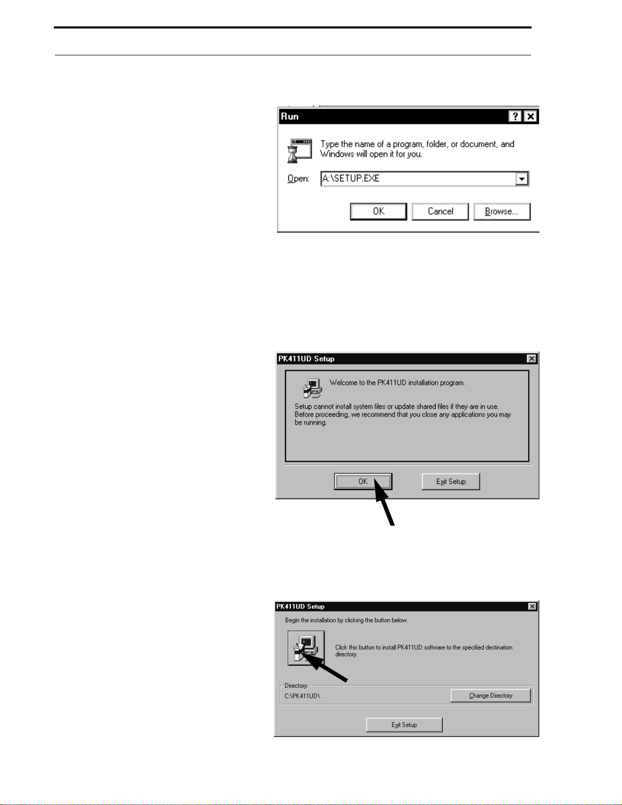
FIGURE 2-1:
Windows® 3.1 Dialog Box
2 .5 Loa ding Softwa re
The PK-411UD software, which is supplied on four 3½"
floppy disks, m ust be loaded onto the hard drive of t he
computer to be used for uploading and downloading to the
411UD/411UDAC Digital Communicator. The software
should be loade d using Windows
2.5 .1 U sin g Windows® To Load PK-411UD
With Windows® 3.1 or higher installed and the Program
Manager being displayed, insert the PK-411U D floppy disk
labeled 'Disk 1 of 4' into the computer floppy drive. Using
the mouse pointer, click 'File' in the Program Man ager menu
line. Using the mouse, click 'Run' to select it from the list of
options under 'File'. The window shown in Figure 2-1 will
be displayed with a cursor blinking in a box labeled
'Command Line'.
With Windows
the 'Start' button. The window shown in Figure 2-2 will be
displayed. Using the mouse pointer, click 'Run' to display
the dialog box shown in Figure 2-3. The cursor will be
blinking in the box labeled 'Open'.
®
95 installed, use the mouse pointer to click
®
.
FIGURE 2-2:
Windows® 95 Start
For Windows
®
3.1 or higher and Windows® 95, type the
following in the Command Line or Open Line:
A:\SETUP.EXE
Document #50802 Rev. B 1/5/99 P/N 50802:B
11
Page 12
Loading Software
If a floppy drive other than A is used, replace A
with the floppy drive in which the PK-411UD
floppy disk is inserted. Click the OK button in this
window. The computer will begin loading the
software from the floppy disk to the hard drive.
Window prompts will appear, instructing when to
insert the remaining disks. The software will also
provide prompts as indicated in “PK-411UD
Installation Prompts” on page 12.
2.5.2 PK-411UD Installation Prompts
One of the first screens to be displayed during the
installation process is shown in Figure 2-4. This
window recommends closing any application programs which may be running, before continuing
with the PK-411UD installation. After closing all
applications, click the OK button.
The window displayed in Figure 2-5 indicates
the default path for loading the software to the
hard driv e. As shown in the prompt , the program
will be loaded on the C drive in a directory called
PK411UD when the button (see Figure 2-5
arrow) is clicked. If you wish to change this
default path, type in the new information after
clicking the 'Change Directory' button.
FIGURE 2-3:
FIGURE 2-4:
Windows® 95 Dialog Box
Insta lla tion to H ard Drive
For example, if you have a partitioned hard drive
containing a D drive, you may load the program
to the D drive partition. If you wish to call the
directory something other than P K411UD, type a
different name such as PROGRAM (limit is 11
characters). To use more than 8 characters, a
period followed by up to 3 characters may be
entered, such as PROGRAM.DIR. To designate
PROGRAM as the directory name, type the
following:
D:\PROGRAM
Click the Install button (indicated by the arrow
in Figure 2-5) to continue the installation. Note
that the last floppy disk, labeled 'Disk 4 of 4',
should remain in the disk drive until installation
is completed.
FIGURE 2-5:
Insta lla tion P ath
12
Document #50802 Rev.B 1/5/99 P/N 50802:B
Page 13
Program Files
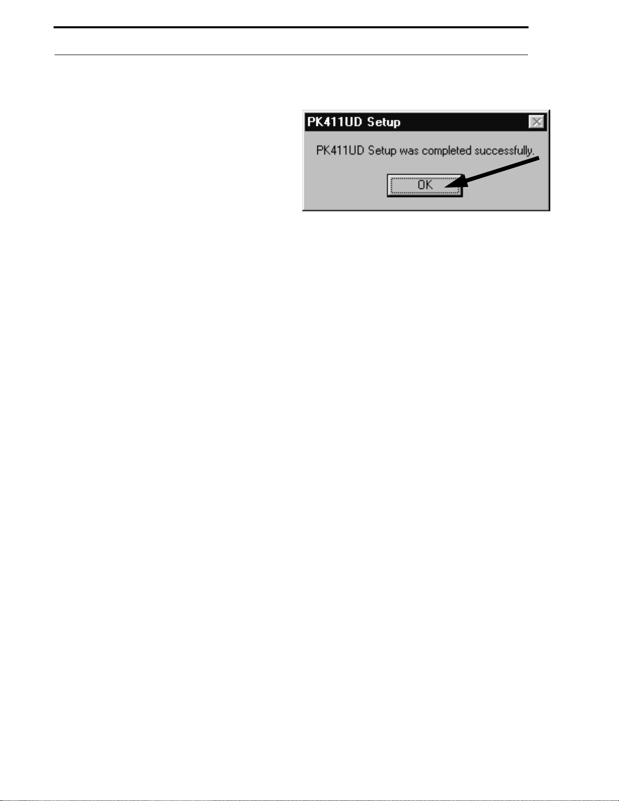
The last installation window, as shown in Figure 2-6,
provides an indication that the installation is completed. Use the mouse arrow to click the OK button
in this window. The final installation process is the
creation of the Upload/Download program ICON.
2.6 Program Files
The PK-411UD Off-Line Programming Utility can
be used in two ways:
• Off-line - program files can be created or
modified for later use
• On-line - the PC is connected to the 411UD/
411UDAC via modem and program files can
be transferred between the two devices.
FIGURE 2-6:
Ins tallat ion Complet ed
Document #50802 Rev. B 1/5/99 P/N 50802:B
13
Page 14
User Interface
CHAPTER 3
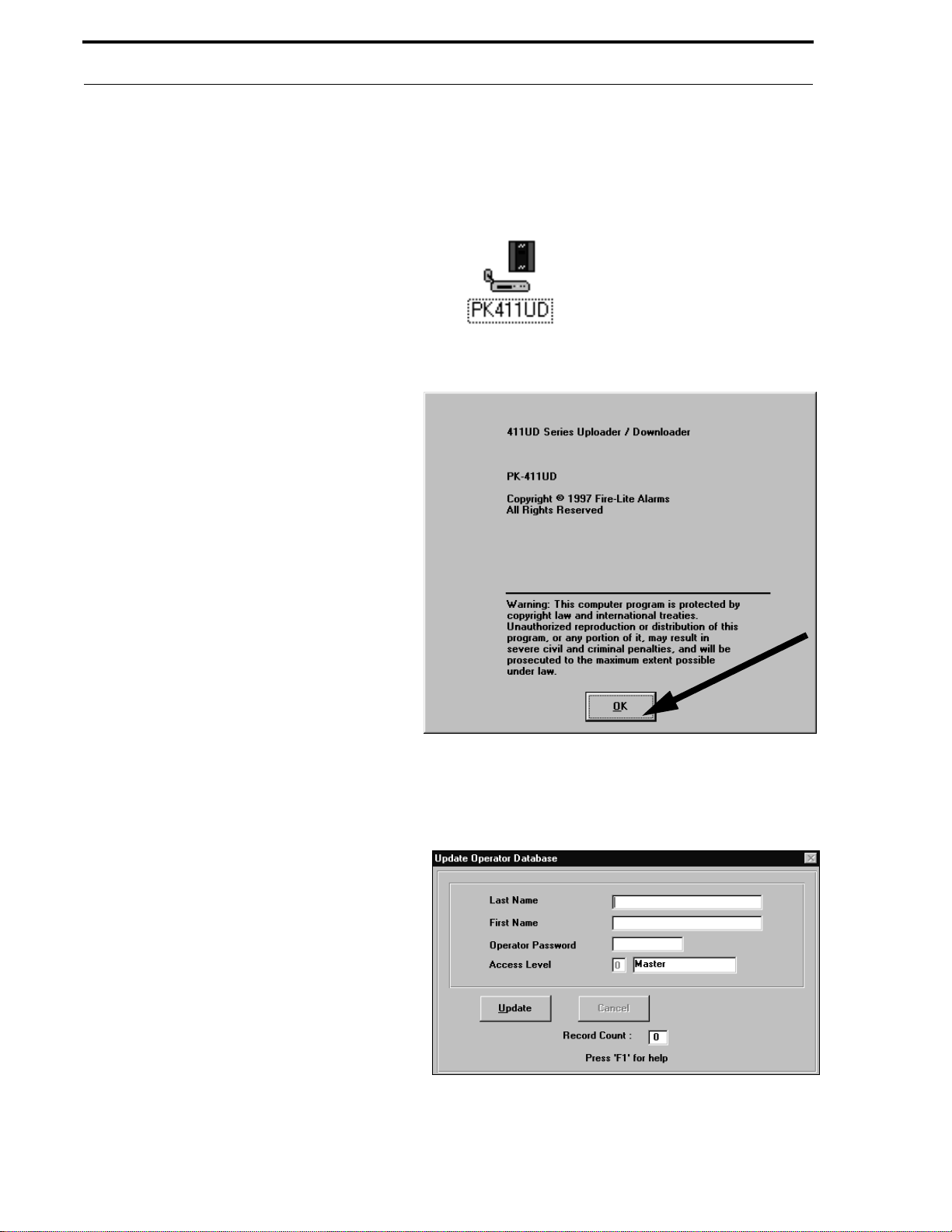
Following the completion of the PK-411UD
program installation, a window is created with the
PK-411UD ICON as shown in Figure 3-1. Run
Upload/Download program by placing the mouse
pointer on the ICON and double clicking.
The Copyright window, the first window displayed
when the PK-411UD program is run, is shown in
Figure 3-2. Read the information displayed before
proceeding with the PK-411UD Upload/Download
program. Clicking the OK button indicates agreement and compliance with this statement.
Note that from this point on, all subsequent menus
can be accessed and functions performed using the
keyboard. This is especially useful when a mouse
is not avai lable. Mo ve bet ween bu ttons or f ields v ia
the 'Tab' key, followed by pressing the 'Enter' key.
Note that all of the windows which appear while the
PK-411UD software is being used can be centered
on the PC (service terminal) screen by pressing and
holding the Control (Ctrl) key while pressing the
'C' key on the key boar d.
User Interfa ce
he
t
FIGURE 3-1:
FIGURE 3-2:
PK-411UD ICON
Copyright W indow
3.1 Initial Use of PK-411UD
The window shown in Figure 3-3 will appear only
on initial use of the PK-411UD Upload/Download
program. The primary (mast er) program operat or is
assigned at this time. The flashing cursor will be in
the top box labeled Last Name. The primary or
master operator types in the last name and then
places the mouse cursor in the First Name box and
clicks. The cursor moves to the next field labeled
First Name where the operator types the first name.
The mouse cursor is placed in the Operator Password box and clicked. The cur sor now mo ves to the
Operator Password field. A user defined password
consisting of at least 1 but not more than 8
alphanumeric characters is typed in. The name and
password should be checked and confirmed for
accuracy. If satisfied with this data, position the
mouse pointer on the Update key and click to store
this information. The software is now registered to
the individual entering this data. This window will
not appear on subsequent start-ups of the
PK-411UD program.
FIGURE 3-3:
Initia lization Windo w
14
Document #50802 Rev.B 1/5/99 P/N 50802:B
Page 15
Initial Use of PK-411UD
3.1.1 Log-in as Master
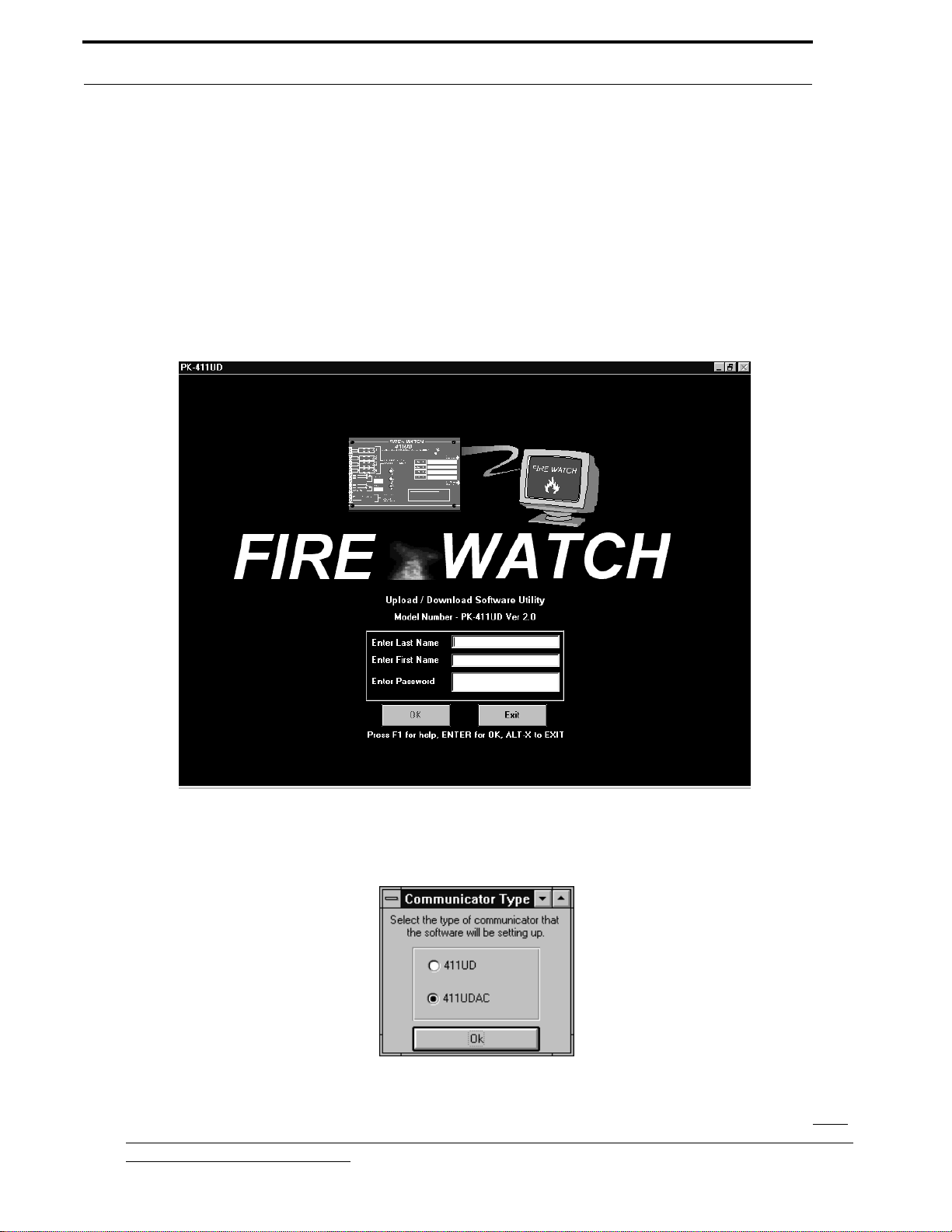
Following the Initialization window shown in Figure 3-3, or each time the Upload/Download program is run after
initialization, the window shown in Figure 3-4 will appear. The operator must type in the Last Name, the First Name
and the previously assigned password. Movement from one entry field to the next is accomplished by pressing the
Enter key, the Tab key or by us ing the mouse arrow to click the next field. Once the Password is keyed-in, click the
OK
button or press the Enter ke y twi ce.
It should be noted that for security reasons, the password is not displayed as it is typed (asterisks appear instead).
Make certain the password is typed correctly since there is no visual confirmation. Any incorrect entries during
Log-in will result in a message window stating 'Error With Log-in'.
FIGURE 3-4:
Log-in
Following a successful Log-in, the window shown in Fig. 3-5 will be displayed.
FIGURE 3-5:
Communica tor S election Window
After selecting the type of Communicat or, the Main Menu window shown in F igure 4-1 wil l be display ed. The menu
options are grouped under the headings of
Data Entry, Utilities, Communications, Setup
Secret Code
and
. Each
menu option is described in the sequence in which it would normally be used for an initial 411UD/411UDAC Digital
Communicator upload or download.
Document #50802 Rev. B 1/5/99 P/N 50802:B
15
Page 16
Setup
CHAPTER 4
The Setup options include:
✓ Operator setup, which allows the creation of new operators
✓ Default Directory and File setup, which allows the configuration of a default program file and
directory
✓ Modem setup, which allows PC and modem configuration
Setup
4.1 Operator
This optional menu selection may be used to create new users and maintain existing operators. The individual
designated as the Master (Level 0 access) during the program initialization process, has access to all program o ptions
and features. The Master may, howeve r , designate an alter nate Master for Le v el 0 or limited access to Le ve ls 1, 2 and
3 as described in the following paragraph.
FIGURE 4-1:
Main Menu - Operator Setup
16
Document #50802 Rev.B 1/5/99 P/N 50802:B
Page 17
Operator
Figure 4-2 shows the window which will be displayed by clicking the Oper ator button. The Name fields in this
display will contain the name of the individual who initially installed the PK-411UD program and is designated the
master. This window allows the master to create alternate masters and designate individuals with lower access levels.
FIGURE 4-2:
Operator Information
The Record Count displayed in the lower right corner of the window indicates the number of individuals with access
to the program. The count following initialization should be 1, since the program in staller (master) is the only one
with initial access.
In the window disp layed in F igure 4- 2, cli ckin g the Pr int button will allow printing of the current operator window or
the entire operator database. Clicking the New button adds new operators. Clicking the Update button allows modification of the current operator information. Clicking the Delete button deletes (with verification) the current opera-
tor. The remaining buttons (except the Exit button) allow navigation through the operator database, in order to view
the operators who have already been entered.
To add a new operator to the access list, click the New button. The window shown in Figure 4-3 will appear. Type
the Last Name, First Name, Password and access level for the new individual. Complete each entry by pressing the
Enter key or clicking on the next field with the mouse pointer. When the password has been entered and the Enter
key pressed, the cursor will move to the Access Level box. Typing the desired Access Level will automatically cause
the adjacent box to display the allowed function for the level. Available Access Levels are as follows:
0 = Master User (all functions)
1 = Upload/Download
2 = Upload Only
3 = View/Print Files
Document #50802 Rev. B 1/5/99 P/N 50802:B
17
Page 18
De fa ult D ire ctor y a nd F ile
Clicking the Cancel button will clear all data entered in this window prior to Updating. Clicking the Update button
will store this information and increment the Record Count by 1. The fields will clear in preparation for new input
data. If no new user is to be added, click the Exit button to return to the Main Operator window. From this window
click Exit to Main Men u to return to the Main Menu selections.
FIGURE 4-3:
Ne w Acce ss
4.2 Default Directory and File
Click the D efault Directory and File button on the Main Menu to customize default directories and program files.
FIGURE 4-4:
Ma in Menu - Configure Directories a nd Files
18
Document #50802 Rev.B 1/5/99 P/N 50802:B
Page 19
De fa ult D ire ctor y a nd F ile
Clicking the De fault Directory and F ile button will cause the window shown in Figure 4-5 to appear.
FIGURE 4-5:
Defau lt Selections
4.2.1 Def ault Directory
The field which is labeled Default Directory displays the drive and directory name, selected by the program, which
will hold files created by the program. In this example, C:\PK411UD is the default path. The drive and/ or d irectory
name may be changed by clicking in the white text block. The window shown in Figure 4-6 will be displayed.
FIGURE 4-6:
Path Locator
This window allows the user to select an alternate path for saving program files by clicking the Down Arrow symbol
in the bottom text block and selecting from the av ailable choices. Clicking the OK button will save the selection and
close the Path Locator window, returning to the window shown in Figure 4-5.
4.2.2 Install Directory
The Install Directory field displays the drive and directory name where the PK-411UD program was installed. This
field is for informational purposes only and cannot be changed.
Document #50802 Rev. B 1/5/99 P/N 50802:B
19
Page 20
De fa ult D ire ctor y a nd F ile
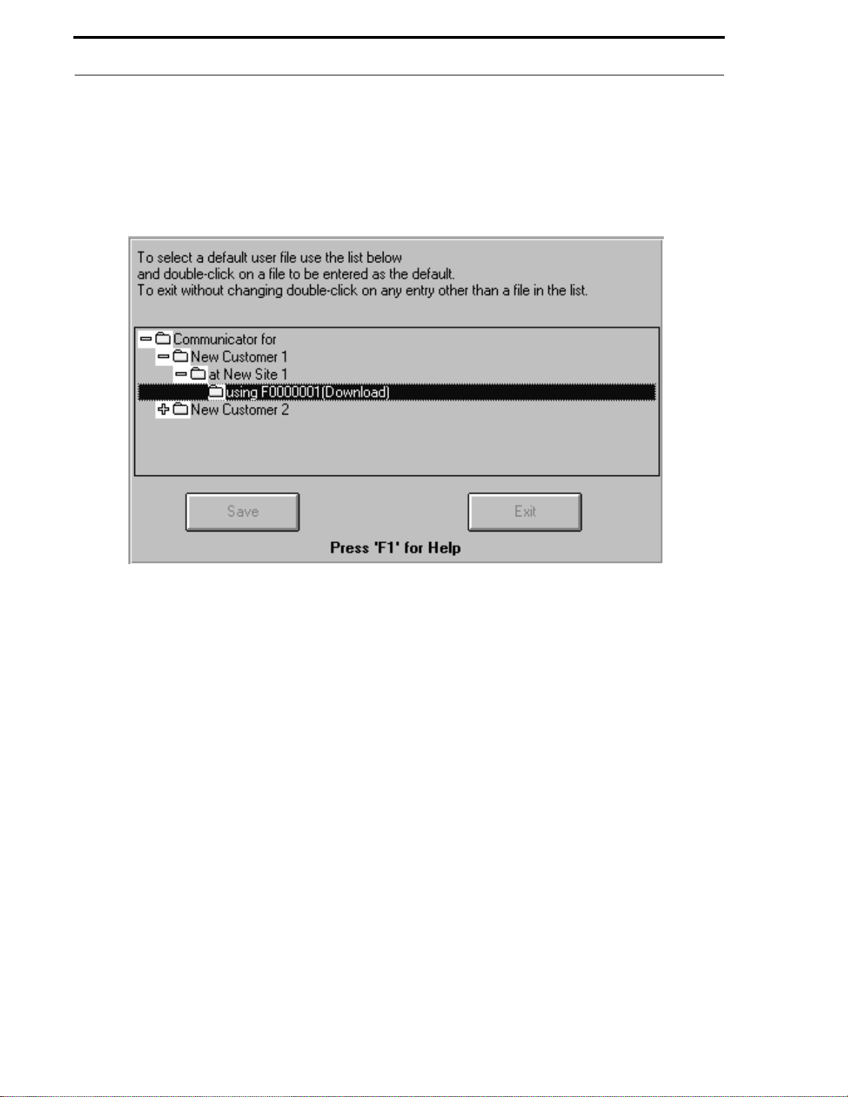
4.2.3 Us er Default Files
User Default File
The
future programming. Clicking in the
displayed.
field allows the user to select a file name which will be used as the default or template file for
User Default File
text block will cause the window shown in Figure 4-7 to be
FIGURE 4-7:
User Default Files
In order to view all av ailable user files, it may be necessary to expand the display en tries by clicking the plus (+) signs
preceding each entry. Click all plus (+) signs until only minus (-) signs appear. The available files follow the
customer and site names. In Figure 4-7, F0000001 is one of the available user files. Double click the file to be used
as the Default User File. The window will close and the selection will then appear in the Default User File text block.
T o exit the window illustrated in Figure 4-7 without selecting a file, double click any entry in the display except a user
file. The program will return to the window displayed in Figure 4-5. Save all selections by clicking the
To exit the window without saving the changes, click the
Exit
button.
Save
button.
20
Document #50802 Rev.B 1/5/99 P/N 50802:B
Page 21

Modem
4.3 Modem
The PK-411UD software must be configured for compatibility with the user's service terminal (PC) communications
ports and modem setup. Click the Modem button in the Main Menu to configure the service terminal for proper
modem operation.
FIGURE 4-8:
Ma in Menu - Configure Mode m
Clicking the Modem button will display the options window shown in Figure 4-9.
FIGURE 4-9:
Co nfig ure Modem
Document #50802 Rev. B 1/5/99 P/N 50802:B
21
Page 22

Modem
4.3.1 Modem
Modem
The
this block will cause a pull-down menu to appear with the list of available modem options as shown in Figure 4-10.
Use the mouse pointer to view additional modems by moving the scroll bar which is located to the right. Select the
desired modem by clicking the appropriate choice. The selection will appe ar in the
FIGURE 4-10:
field is used to select the type of modem being us ed. Clicking the Down Arrow symbol to the right of
Modem
Modem Selec tion
text block.
Scroll Bar
Note that it is possible to add to the existing modem list by clicking in the Modem text block and typing the name of
a modem model. The Initialization String and Hangup String can then b e customized as described in the following
paragraphs. After clicking the
Save
button, the new modem(s) will be saved with the Initialization String and
Hangup String and the modem name will appear in the pull-down menu.
4.3 .2 Initialization Stri ng
Selecting a modem from the existing list will cause the standard
entered in the te xt bl ock as illust rated in Fig ure 4-11 . The
drop-down window, cannot be changed. AT Commands, which appear in the
separated by semicolons (;). The semicolons allow all commands to be sent, e ven if o ne should fail. If the user wishes
to customize a specific initialization string, select the appropriate modem which will cause an initialization string to
appear in the text block. Change the name of the modem by clicking in the
name. The string may now be customized by clicking in the
desired information which may be found in the appropriate modem manual.
FIGURE 4-11:
Ini tializ ation St ring
Initialization String
Initialization Strings,
Initialization String
Modem
Initialization String
for the selected modem to be
for the modems which appear in the
text block, are
text block and typing a new
field and entering or deleting the
22
Document #50802 Rev.B 1/5/99 P/N 50802:B
Page 23
Modem
4.3 . 3 Han g up String
Hangup String
The
field is used t o enter the modem co mmand req uired t o hang up or discon nect the modem f rom t he
phone line. The factory default is 'H'. Refer to the specific modem manufacturer's manual for the required Hangup
String and enter the appropriate information by double-clicking in the Hangup text block and typing the new data.
4.3.4 Communication Port
Comm Port
selection (COM1 through COM4) determines the location of the physical connection for the modem.
An internal or external modem may be used. This selection depends on the service terminal's available serial connectors. Refer to the service terminal (PC) technical manual for additional information. An
vided which allows the software to determine which port is co nnected to the modem. Clicking on the
Auto-Detect
button is pro-
Auto-Detect
button will cause the software to send modem test signals to all ports. Messages detailing the presence or absence of
a modem will be displayed in the Modem Communications text block as the tests are generated. If multiple modems
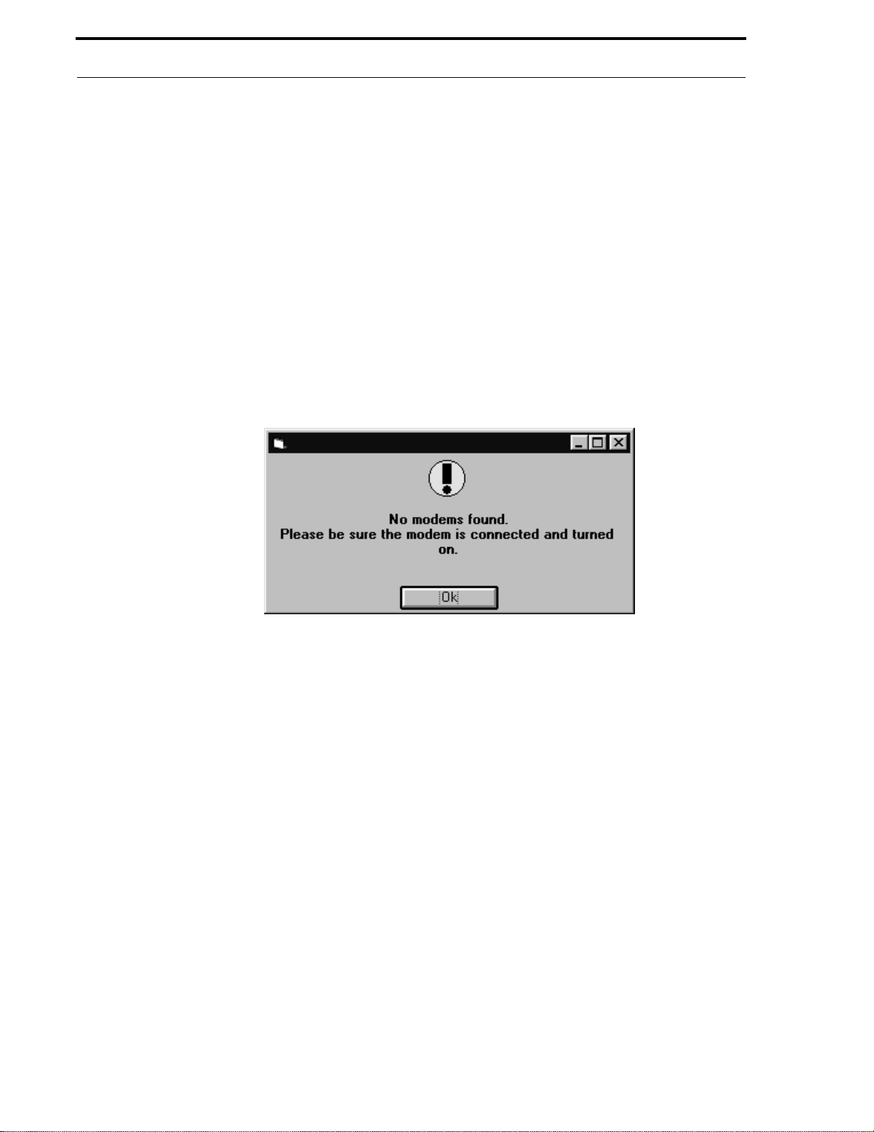
are installed, the first modem found will be selected. If no modem is detected, the window shown in Figure 4-12 will
be displayed.
FIGURE 4-12:
No M odem Found Window
The Baud Rate, which is the data transmission speed, is fixed at 1200 bps (bits per second).
4.3.5 Modem Initialization and Testing
Test features have also been incorporated into the modem window. Clicking the
initialization string to the PC modem in order to test the modems functionality. Test messages will be displayed in the
Modem Communications text block. Entering a modem phone number in the corresponding field and clicking the
Dial
button will test the service terminal modem's ability to dial out. Clicking the
service terminal to disconnect the call to the modem.
If during initialization, a particular AT Test fails, the information will be displayed in the
text block. Enter the failed AT Test in the
AT Test Co mmand
text block and click the
AT Test will be generated to the modem with the test results being displayed in the
block. The
Cl ear Di spla y
button clears all messages from the
Modem Comm uni cations
Initialize
Hangup
button will send the
button will cause the
Modem Comm uni c a ti o ns
Send
button. The designated
Modem Communica tions
text block.
text
4.3.6 Saving Modem Settings
After completing the communications configuration, click the
Initialization String, Hangup String and Com m. Port selection and return to the Main Menu. These settings should
not require further editing unless a different modem is to be used. Clicking the
Menu without saving the settings just selected.
Save
button to store the modem selection,
Exit
button will access the Main
Document #50802 Rev. B 1/5/99 P/N 50802:B
23
Page 24

Data E n try
CHAPTER 5
The Data Entry functions include the Customer option whi ch allo ws the user to desi gnate a customer name, customer
site and create a program file for the specific 411UD/41 1UD A C. The Modified Fields option allows the user to view
the programming features which have been altered during editing.
FIGURE 5-1:
Main Menu
Da ta Entr y
24
Document #50802 Rev.B 1/5/99 P/N 50802:B
Page 25

Customer
5.1 Customer
The Customer option allows the user to enter and store specific customer and site location information as well as the
program file for the 411UD/411UDA C located at the customer site. Note that program files created on the PC will be
1
saved as files with a .dl
will be saved with a .ul
display the window shown in Figure 5-2. Since customer information has not yet been entered, the Customer/Site/
File text block will not contain any customer information. Note th at on subsequent use of the Customer button,
customer information may appear in the window.
(download) extension and files retrieved from an 411UD/411UDAC Digital Communicator
1
(upload) extension. Clicking the Customer button, during the first use of the program, will
FIGURE 5-2:
Cus tom e r Files
5.1.1 Adding Customer to Database
To add a customer to the database, begin by clicking the Co mmunica tor For text which is located in the bottom left
corner of the window. An Add Customer button will appear as shown in Figure 5-3. This step must be followed
each time a new customer is to be added.
FIGURE 5-3:
Add Customer Button
Document #50802 Rev. B 1/5/99 P/N 50802:B
25
Page 26

Customer
Click the Add Customer button shown in Figure 5-3 to enter a new customer into the database. The blank customer
information window shown in Figure 5-4 will be displayed and will allow the entry of customer information.
FIGURE 5-4:
Custome r E ntr y window
The optional customer text which is entered in each f ield is used as a reference only. The customer information is not
sent to the 411UD/411UDAC during programming. To enter the Custome r N ame , highlight the text in the white
block to the right of this field and then type the customer name. Click in the Address 1 text block or use the Tab key
to move to the next field and type the appropriate information. Continue this process until the desired information is
entered in each block. Note that it is not necessary to enter text into every text block. Information is not saved until
the Save Customer button is clicked.
Note in Figure 5-4, that the Add Customer button shown in Figure 5-3, has changed to the Add Site button and the
Delete Customer button is no w di sp l ayed. To delete a customer from the database, click the plus (+) sign located in
front of the text Communicator for to view customer names in the database. T o view all customers, click all plus (+)
signs which appear in the Customer/Site/File block. Click the customer name to be deleted and click the Delete
Customer button. A confirmation window will appear asking if you are sure that you wish to delete the customer.
Clicking Yes will delete the customer, customer site and associated program files. Clicking No will cancel the
deletion.
26
Document #50802 Rev.B 1/5/99 P/N 50802:B
Page 27

Customer
5.1.2 A d d Cus tomer Site Info rmation to Databa s e
Information about the location of the customer's 411UD/411UDAC may also be added to the database. Click the
Add Site
button to display the window shown in Figure 5-5.
FIGURE 5-5:
The optional customer site text which is entered in each field is used as a reference only, except for the
Number
, which must be entered to allow the service terminal software to call the 411UD/411UDAC. The remaining
Custome r S ite Informa tion
Site Phone
customer site information is not sent to the 411UD/411UDAC during programming. The Customer Name located at
the top of the window is used to reference the site being edited and cannot be changed. To enter the
Name
, highlight the text in the white block to the right of this field and then type the site contact name. Click in the
Site Contact
Site Street Address 1 text block or use the Tab key to move to the next field and type the appropriate information.
Continue this process until the desired information is entered in each block. Note th at it is not necessary to en ter te x t
into every text block. Click the
Save Site Information
button to save the information.
After clicking the
Add File
text
and
Comm unicator fo r
Add Site
Delete Site
button shown in Figure 5-4, the
buttons. To delete a site from the database, click the plus (+) sign located in front of the
to view customer names and sites in the database . To view all customers and sites, click all
plus (+) signs which appear in the
Delete Site
button. A confirmation window will appear asking if you are sure that you wish to delete the site.
Customer/Site/File
Add Site
Delete Customer
and
buttons are replaced by
block. Click the customer site to be deleted and click the
Clicking Yes will delete the customer site and associated program files. Clicking No will cancel the deletion.
5.1.3 Add Program File to Database
The user may now create the 411UD/411UDAC Digital Communicator program file which will be downloaded to the
communicator at the customer's site. Clicking
FIGURE 5-6:
Filename
Document #50802 Rev. B 1/5/99 P/N 50802:B
Add File
will display the window shown in Figure 5-6.
27
Page 28

Customer
A default filename appears in the text block. Note that a program file has not yet been created, only a program filename. The default f ile name may be u sed or a ne w nam e can be enter ed by highli ghting t he tex t and typ ing in the n e w
1
filename. A maximum of 8 characters can be entered. The .dl
(download) extension will be added automatic ally
when the filename is saved. Click the OK button to add the new filename to the database. Click the Cancel button to
prevent the addition of the filename to the database. Clicking the OK button will automatically load the factory
default program if this is the first program file being created with the PK-411UD software. The window illustrated in
Figure 5-8 will appear. Clicking the OK button in this window will create a new program file with the filename created in Figure 5-6.
If program files have previously been created using the PK-411UD software, clicking the OK button in the window
illustrated in Figure 5-6 will cause the window shown in Figure 5-7 to be displayed. The User Def ault button will
appear only if a Default File has been assigned (refer to Figure 4-5 on page 19). The Current I n formation button
will appear only if a program file has been recalled and is currently in memory.
FIGURE 5-7:
Ex ist ing F i le Selecti on
To create a new program file referenced by the filename created in Figure 5-6, click the Factory Default, User
D efault or Current Informa t ion button. The window shown in Figure 5-8 will appear, indicating that a new
program file, for the current customer, has been created.
FIGURE 5-8:
New File
Clicking the OK button will cause new buttons to appear in the Customer Files window, as illustrated in Figure 5-9.
28
Document #50802 Rev.B 1/5/99 P/N 50802:B
Page 29

Customer
.
FIGURE 5-9:
Custome r F ile s Window - Central Station
The Save button is used to save new or updated information, entered in this window, to the filename indicated in the
Comm unicator F ile name text block. The Recall button is used to display the data stored in the file indicated in the
Comm unicator F ile name text block.
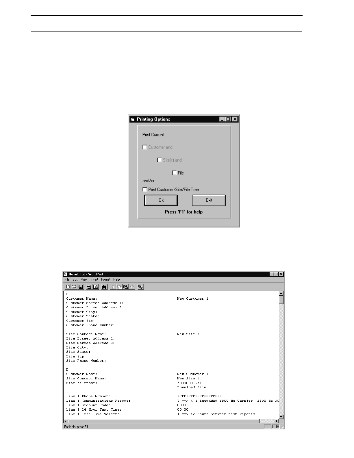
5.1.4 Print Options
The Print button, located at the bottom of the windo w, is used to print customer, site and p rogram f i le information. If
Comm unicator for is highlighted in the Customer Files w indow shown in Figure 5-9, clicking the Print button will
display the window shown in Figure 5-10.
FIGURE 5-10:
Printing O p tio ns Window - Pr i nt A ll
Document #50802 Rev. B 1/5/99 P/N 50802:B
29
Page 30
Customer
This option allows the user to print the database content for all customers, all sites and all program files or any
combination of choices.
If a specific Customer, Site or Fi le is highlighted in the Customer window shown in Figure 5-9, clicking the Print
button will display the window shown in Figure 5-11. This option allows the user to print the database content for the
currently selected customer, site or pr ogr am file or any combination of these choices. If File is highlighted in Figure
5-9, only File will be available for printing as shown in Figure 5-11. If Site is highlighted in Figure 5-9, Site and
File will be available for printing. If Customer is hi ghli ght ed in the Cu sto mer wind o w, Customer , Site and File will
be available for printing.
FIGURE 5-11:
Pr int C urrent
After the print selections have been made, clicking the OK button will cause the window shown in Figure 5-12 to be
displayed. This WordPad text window displays the data which was selected for printing. Clicking File in the menu
bar and then clicking Pr int in the File drop-down menu will start the print process.
FIGURE 5-12:
Print Text
30
Document #50802 Rev.B 1/5/99 P/N 50802:B
Page 31
Customer
5. 1.5 Cus to mi zing Pro gram Fil e s
Note that, in addition to the print optio n, a ser ies of four b ut tons, which are use d for prog ramming , are no w dis played
in the window shown in Figure 5-9. All program information for the current customer and site will be stored under
the filename which appears in the text block labeled
Communic ator Filename
. Below this block, the Upload/Down-
load field will indicate whether the file is an Upload File (retrieved from a communicator) or a Download File
1
(created on the PC). Upload files are automatically saved with a
1
.dl
extension.
.ul
extension and Download files are saved with a
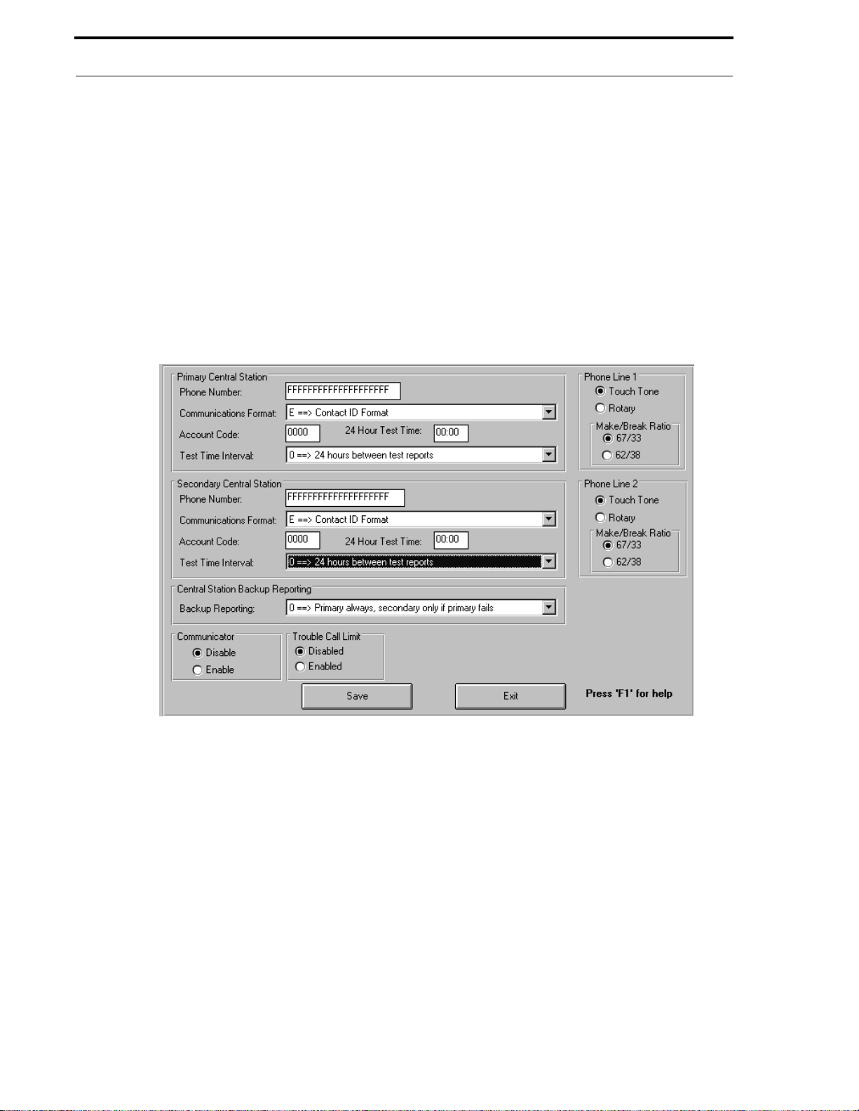
5.1.5.1 Central Station Programming
To program Central Station data, click the
FIGURE 5-13:
Central Station Programming
Central Stati on
button to display the window shown in Figure 5-13.
Enter the appropriate programming data in this window. The Central Station phone numbers are the numbers the
digital communicator uses to contact the Central Station. Click in the far left of the Phone Number text block for the
Primary Central Station text block. The cursor should appear to the left of the first 'F' in the text block. Type the
appropriate phone number. Each typed digit will replace an 'F' in the text block. When the entire phone number has
been entered, any remaining 'Fs' indicate the end of the num ber. Follow the same procedure for entering the
Terminal 2 Pho ne Number
. Valid phone number entries are '0' through '9'. In addition, 'A' through 'F' can be
Service
entered to represent the follo w ing:
A = * (symbol on a touch tone phone)
B = # (symbol on a touch tone phone)
C = look for secondary dial tone for up to 2 seconds, then dial anyway
D = 3 second pause
E = 5 second pause
F = end of phone number
Document #50802 Rev. B 1/5/99 P/N 50802:B
31
Page 32
Customer
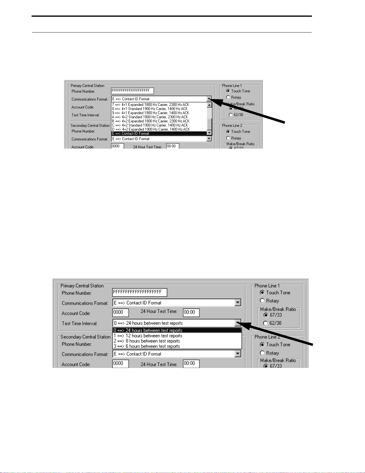
Click the down arrow to the right of the Communications Format text block, t o view the available format options as
illustrated in Figure 5-14. Use the scroll bar to view all formats. Clicking the desired communicatio ns format will
cause the selection to appear in the Communications Format text block.
FIGURE 5-14:
Communications Format
Each 411UD/411UDAC digital communicator is assigned a unique Account Code by the Central Station, which is
used for identification purposes. Double click in the Account Code text block and enter the appropriate three or four
digit account code. The number of digits entered will match the Communications Format selection. If the communications format selected is '2, 3, 4 or 5', a three digit account code will be assigned and must be entered. If the communications format selected is '0, 1, 6, 7, 8, 9, A, B, C, D or E', a four digit account code will be assigned and must be
entered.
Double click in the 2 4 Hour Test Time text block and enter the time that the digital communicator will call in the 24
hour test message to the Central Station. This entry must be made in military time with valid entries being '0000'
(midnight) to '2359' (11:59 PM).
Click the down arrow to the right of the Tes t Time I nterva l text block to view the available options as illustrated in
Figure 5-15. Clicking the desired T est T ime In terv al will cause the selection to appear in the Test Time Interval text
block.
FIGURE 5-15:
Test Time Interval
Select the type of phone service being used for Phone Line 1 by clicking the Touch Tone or Rotar y text which is
located to the top right of the window. Refer to Figure 5-15 for the location of these selectio ns. A dot will appear in
the white circle preceding the selected service.
If Rotary phone service has been chosen, select the Make/Break Ratio for Phone Line 1 b y clicki ng 67/33 or 62/38.
Refer to Figure 5-15 for the location of these selections. A dot will appear in the white circle preceding the selected
ratio.
32
Document #50802 Rev.B 1/5/99 P/N 50802:B
Page 33
Customer
After completing all entries for the Primary Central Station, continue progr amming the Secondary Central Station.
Begin by clicking in the far left of the text block for the Se condary Ce ntral Station Phone Number. The cursor
should be flashing to the left of the first 'F'. Type the appropriate phone number. Follow the same procedures used
for entering all programming data for the Primary Central Station.
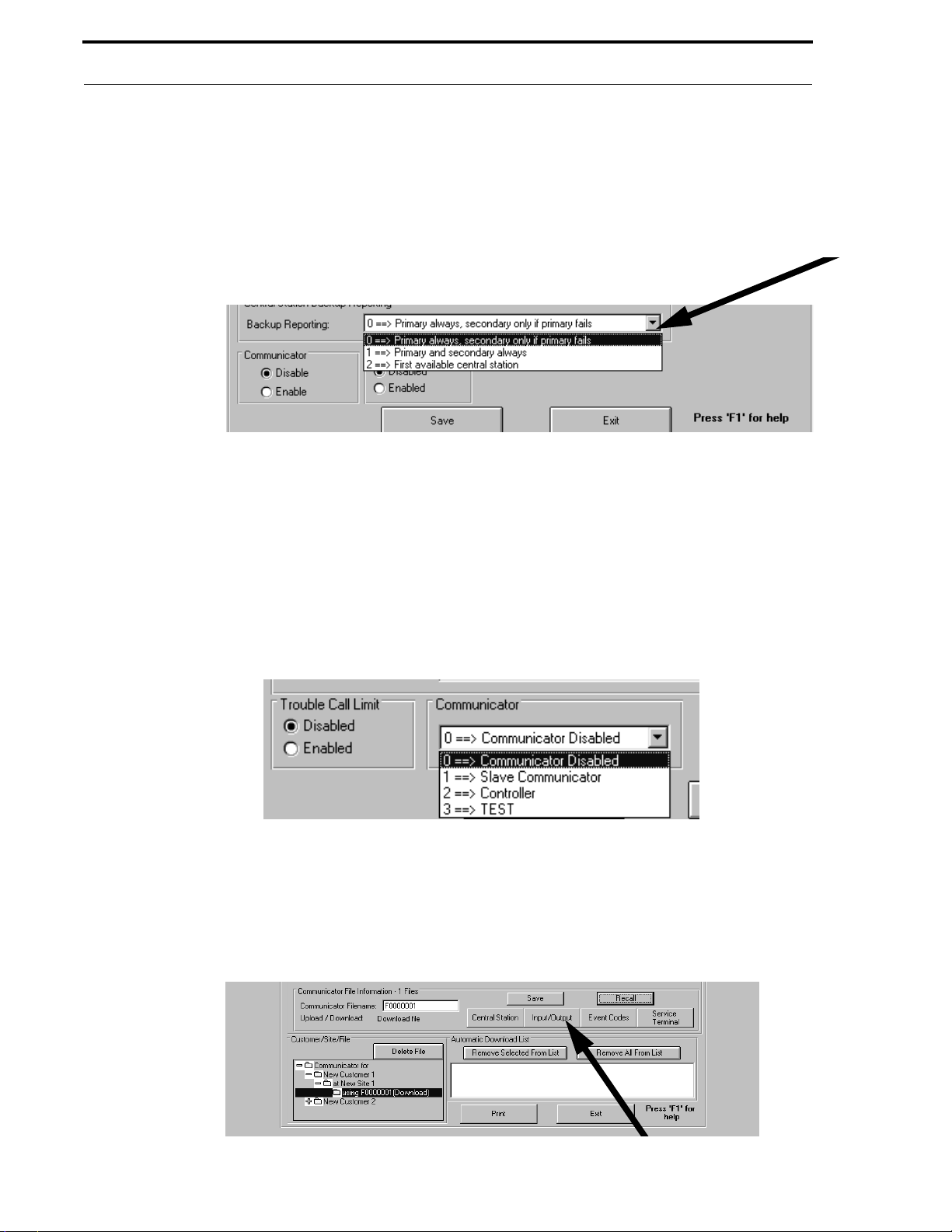
Program Central Station Backup Reporting by clicking the do wn arro w, located to the right of the Backup Reporting
text block. A drop-down window with a list of available options will appear, as illu strated in Figure 5-16. Clicking
the desired selection will cause the choice to appear in the Backup Re porting text block.
FIGURE 5-16:
Backup R eporting
The Trouble Call Li mit option is located to the left of the Central Station Program window. Clicking Disabled
will allow the communicator to call in all trouble messages to the Central Station, includi ng an unlimited number of
repetitive troubles. Clicking Enabled will limit the number of repetitive trouble calls to 10 for each unique trouble
within a 24 hour period. This will not limit the number of phone line (communications) troubles.
The Communicator Disable and SLAVE Communicator selections for the 411UD or the Communicator Disable,
Slave Communica tor, Controller and TEST selections for the 411UDAC are located to the left of the Trouble Call
Limit option. Refer to Figure 5-17 for the location of these options. Selecting the Disable text will prevent the
digital communicator from calling in to the Central Station. Selecting the Slave or Control l er text allows the
communicator to send messages to the Central Station.
FIGURE 5-17:
Communica tor Disable /Trouble Call Limit Options
Click the Save button to save all information programmed in this window and then click the Exit button. Clicking
the Exit b utton before cl icking the Sa ve button will close this window without saving the data entered in this window.
The Central Station window will close and the Customer Files window shown in Figure 5-18 will reappear.
5.1 . 5.2 Input/Output Prog rammi ng f o r the 411U D
FIGURE 5-18:
411UD Customer Files Window
Document #50802 Rev. B 1/5/99 P/N 50802:B
33
Page 34
Customer
Clicking the Input/Output button on the Customer Files window will cause the window shown in Figure 5-19 to
appear.
FIGURE 5-19:
41 1UD I nput/Output Window
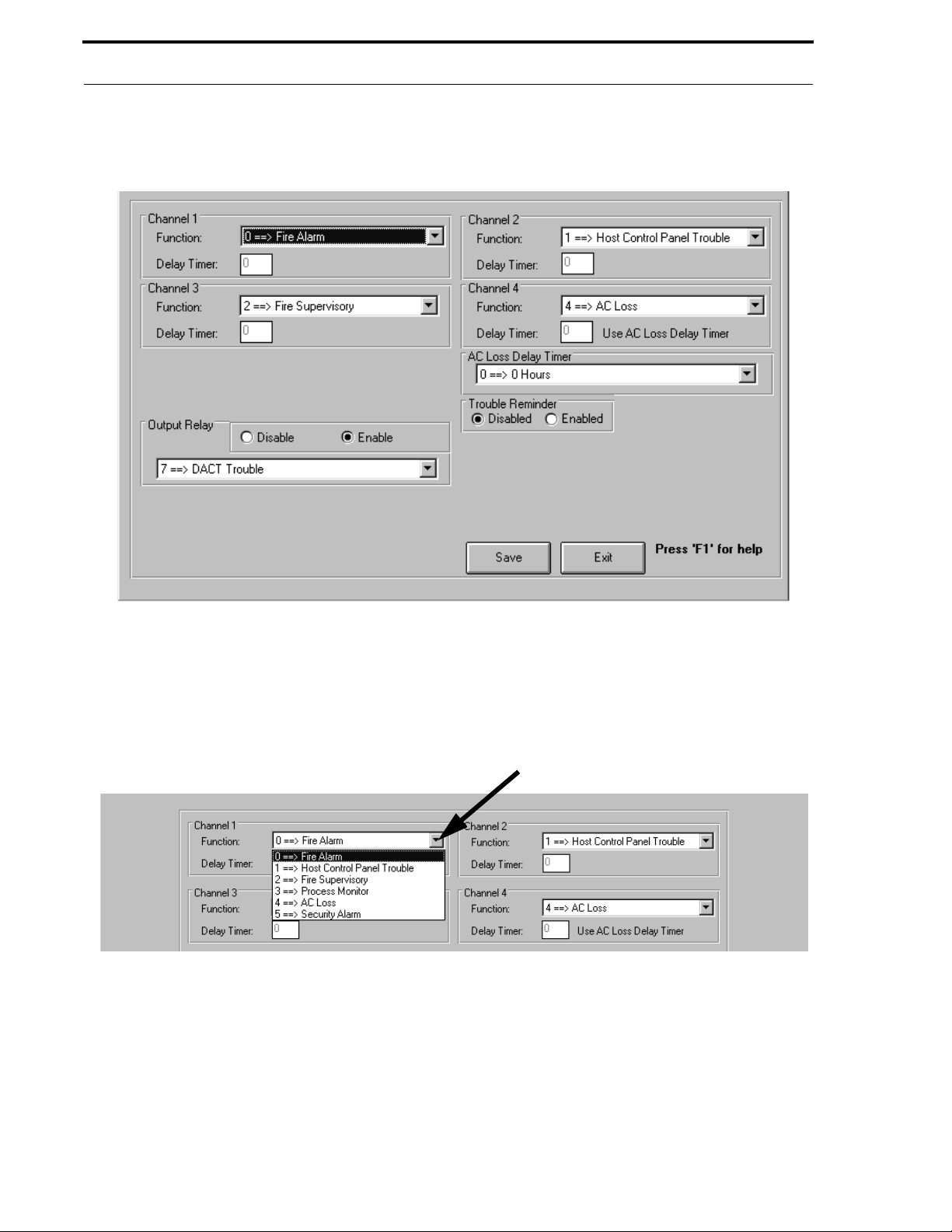
The Input/Output window allows the programming of each of the four channels and the output relay. In addition, the
AC Los s D e lay Timer can be programmed and the Trouble Reminder can be enabled or disabled.
Begin by programming Channel 1. Click the down arrow to the right of the Channel 1 Function text block to view
the available options as shown in Figure 5-20.
FIGURE 5-20:
41 1UD Input Function Selection
Clicking the desired selection will cause it to app ear in th e Function text block.
The Delay Timer text block will be enabled only if function 3 (Process Monitor) or function 5 (Security) is selected.
A default entry of zero (0) will not delay the reporting of a process monitor or security alarm to the Central Station.
T o delay the reporting of either of these functions, double click in the Delay Timer text block and enter a delay value
of from 1 second to 179 seconds.
The programming of Channel 1 has been completed. Continue with the programming of Channels 2, 3 and 4 by
following the same procedures outlined for Channel 1.
34
Document #50802 Rev.B 1/5/99 P/N 50802:B
Page 35
Customer
To program the Output Relay, click the down arrow to the right of the Output Relay text block to view the available
options as shown in Figure 5-21.
FIGURE 5-21:
411UD Output Relay Programming
Clicking the desired selection will cause the ch oice to appear in the Output Re lay text block. To enable the relay,
click the Enable text located above the text block. A black dot will appear in the white circle preceding the text,
indicating that the relay has been enabled. To disable the relay, click the Disable text. A black dot will appear in the
white circle preceding the text, to indicate the relay has been disabled. The programming of the Output Relay is
complete.
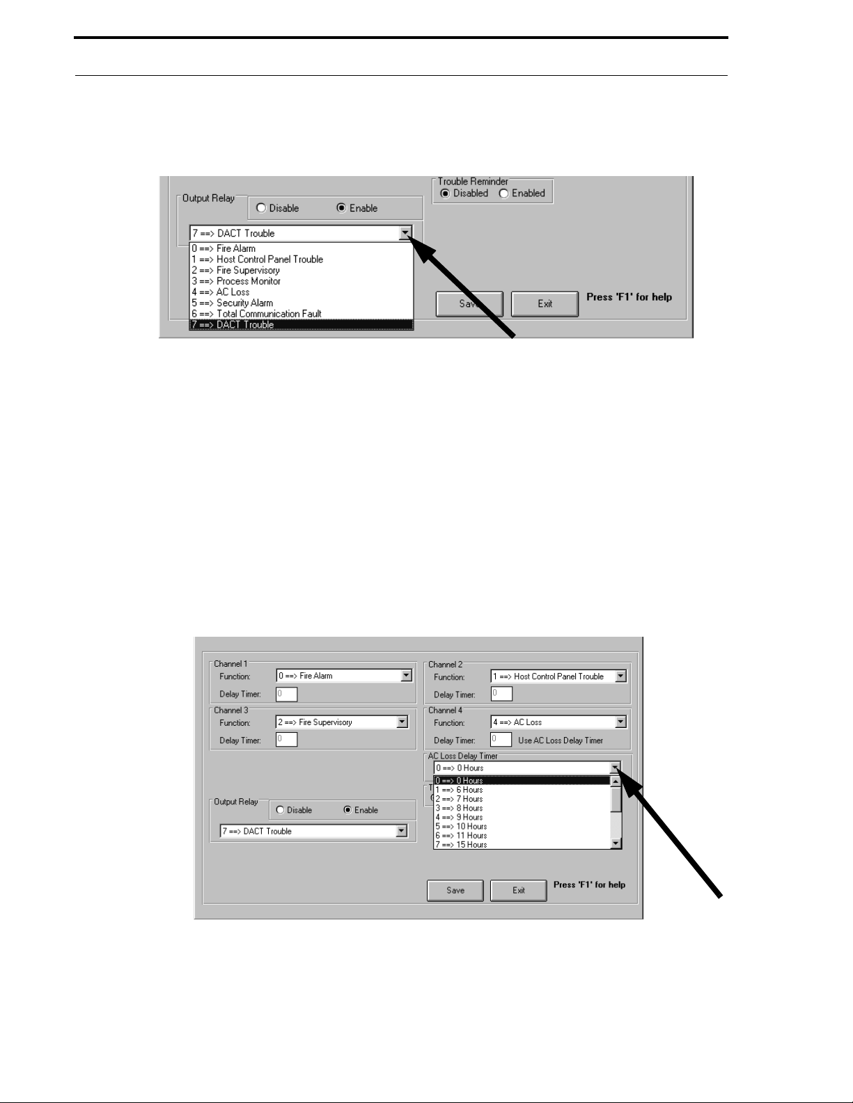
The AC Lo ss Delay Timer option can be programmed in this window if any Channel is programmed as AC Loss.
This option allows the digital communicator to delay sending an AC loss message to the Central Station for the
selected time period. Click the do wn arro w to the right of the AC Loss Delay Timer text block to vie w the av ailable
options as sho wn in F igure 5- 22. Use the scro ll b ar to view all of the options in this drop down window . C licki ng th e
desired time delay will cause the selection to be displayed in the AC Loss Delay Timer text block.
FIGURE 5-22:
411UD Option Programming
The Trouble Re m i nder option causes the digital communicator piezo to 'beep' every two minutes during a trouble
condition, after a trouble silence switch has been pressed. Click the Enabled text to enable this feature. A black dot
will appear in the white circle preceding the text to indicate the selection of this option. Click the Disabled text to
disable the Troub le Re minder feature. A black dot will appear in the white circle preceding the text to indicate that
the option has been disabled.
Document #50802 Rev. B 1/5/99 P/N 50802:B
35
Page 36
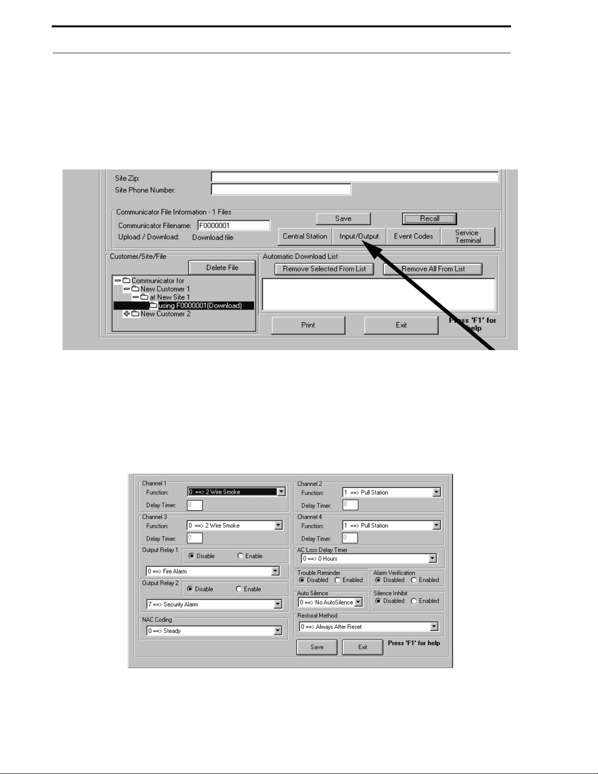
Customer
Click the Save button to save all information programmed in this window and then click the Exit button. Clicking
the Exit b utton befo re clicking the Sa ve button will close this window without saving the data entered in this window.
The Input/Output window will close and the Customer Files window, as illustrated in Figure 5-18, will reappear.
5.1 . 5.3 Input/Output Prog rammi ng f or the 411UDAC
FIGURE 5-23:
411UDAC Customer Files Window
Clicking the Input / Output button in the Custome r Fi les window will cause the Inpu t/Output window shown in
Figure 5-24 to appear.
Programming of each of the 4 chann els an d two output relays is accomplished through the Input/Output window. In
addition, options for NAC Co ding, the AC Loss De lay Timer, Auto Silence and Restoral Method as well as the
settings for Trouble Re minder, Alarm Verification and Sil ence Inhibi t are selected in this window.
FIGURE 5-24:
Input/ Output Window for the 411U D AC
36
Document #50802 Rev.B 1/5/99 P/N 50802:B
Page 37
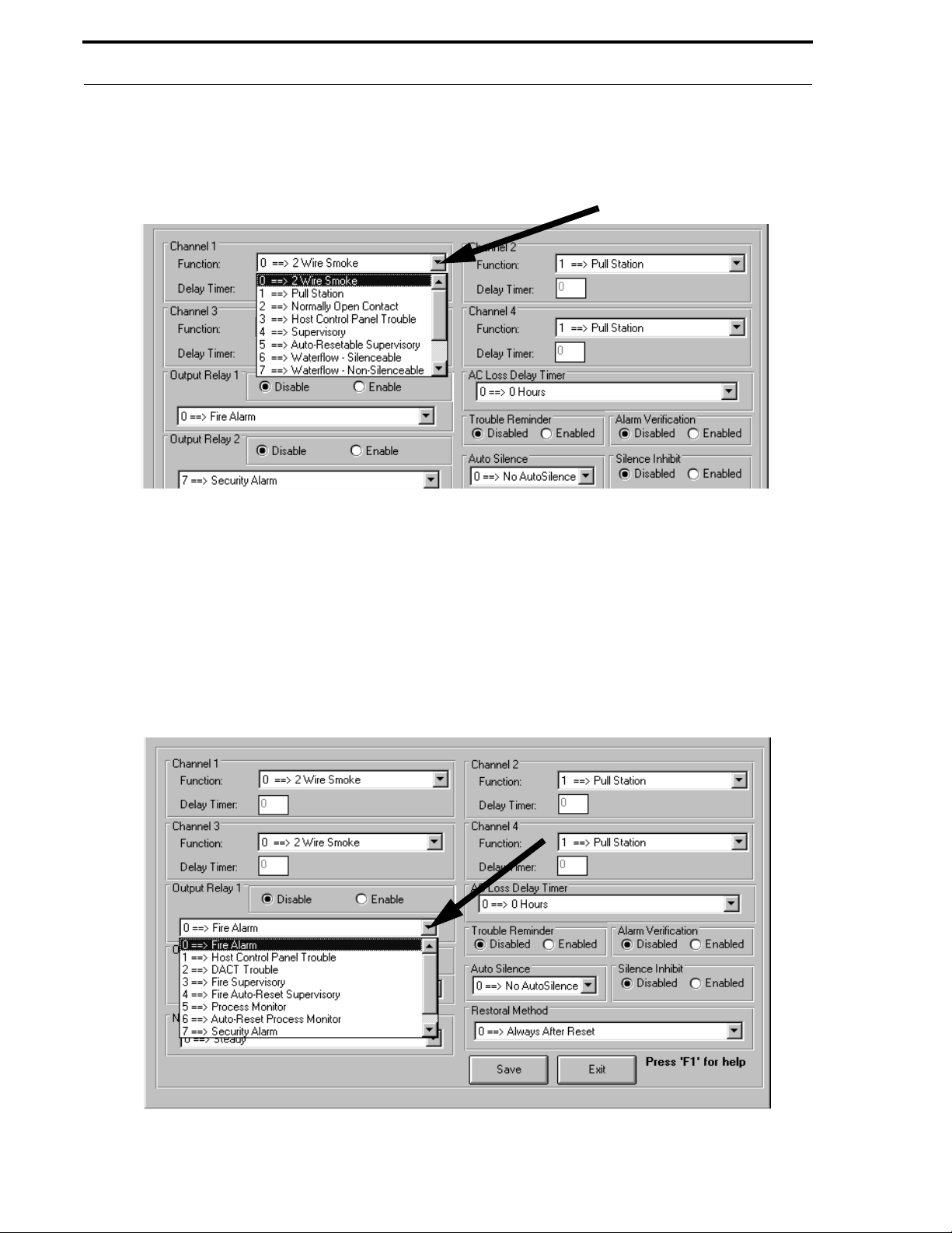
Customer
Begin by programming Channel 1. Click the down arrow to the right of the Channel 1 Functi on text block, as illustrated in Figure 5-25, to view the available options. Clicking the desired selection will cause it to appear in the
Function text block.
FIGURE 5-25:
41 1UDAC Channel 1 - Input/output Window
The Delay Timer text block will be enab led only if function 6, 7, 8, 9 or A is selected. A default entry of zero (0)
will not delay the reporting of these functions to the Central Station. To delay the reporting of any of these functions,
double click in the Delay Timer text block and enter a delay value of from 1 second to 179 seconds.
The programming of Channel 1 has been completed. Continue with the programming of Channels 2, 3 and 4 by
following the same procedures outlined for Channel 1.
Click the down arrow to the right of the Output Rel a y 1 text block, as illustrated in Figure 5-26, to see the available
options. Select one of the options displayed to program the Output Rela y. Program Relay 2 in the same manner.
FIGURE 5-26:
41 1UD AC Output Relay Options
Document #50802 Rev. B 1/5/99 P/N 50802:B
37
Page 38
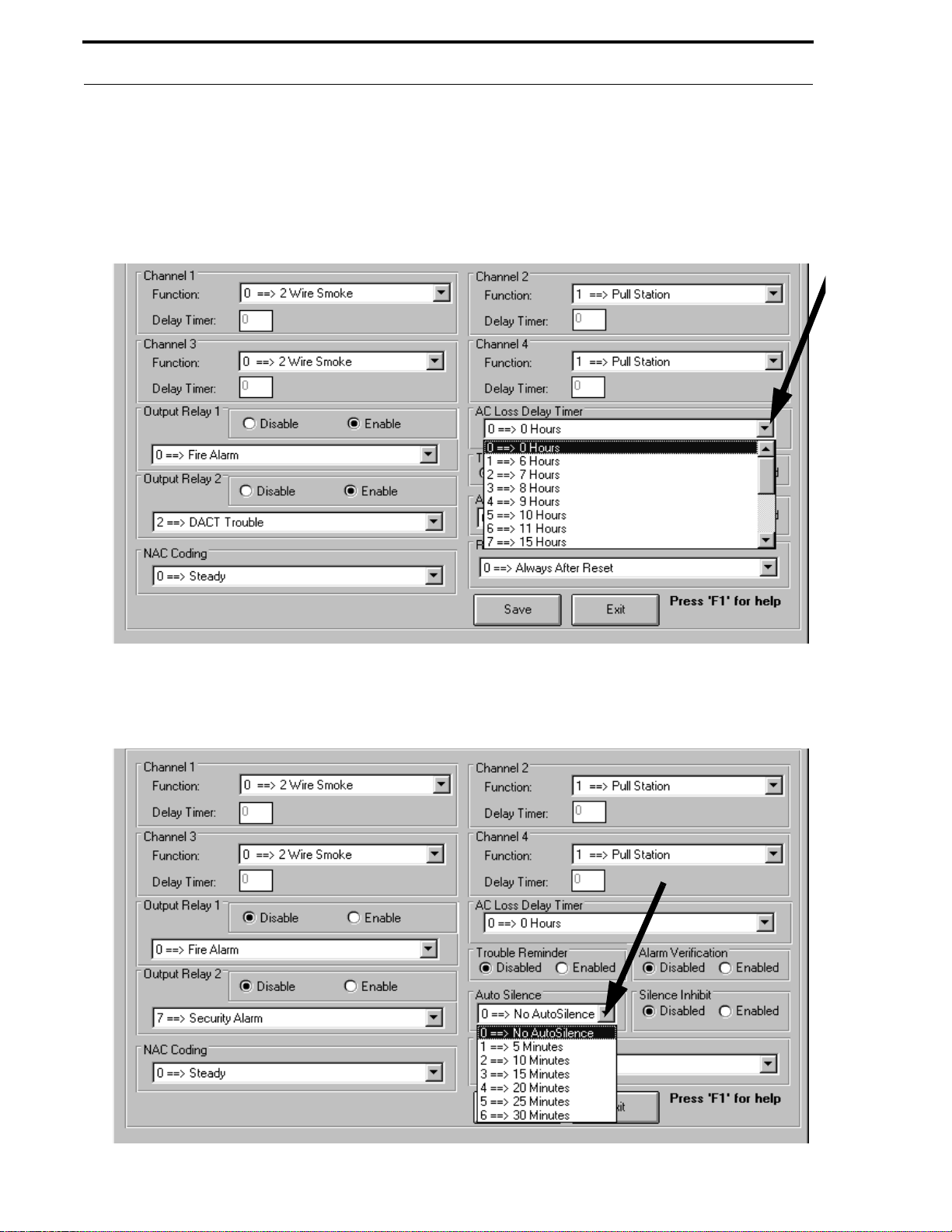
Customer
The AC Loss Delay Timer option can be programmed in this window if any Channel is programmed as AC Loss.
This option allows the digital communicator to delay sending an AC loss message to the Central Station for the
selected time period. Click the do wn arrow to the right of the AC Loss Delay Timer text block to view the av ailable
options as shown in Figure 5-27. Use the scroll bar to view all of the options. Clicking the desired time delay will
display the selected option in the AC Loss Del ay Timer text block.
FIGURE 5-27:
AC Lo ss Delay Timer Opt ion s for the 411U DAC
To program the Auto Silence option, click the down arrow to the right of the Auto Silence text block to see the
available options as illustrated in Figure 5-28.
FIGURE 5-28:
411UDAC Auto Silence Options
38
Document #50802 Rev.B 1/5/99 P/N 50802:B
Page 39
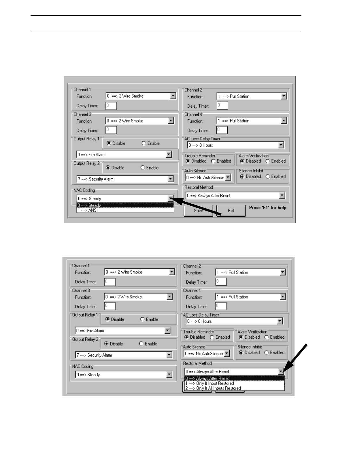
Customer
The NAC Coding option is located at the bottom left of the Input/Output programming window. Use the arrow at the
right of the text block in Figure 5-29 to display the available options. .
FIGURE 5-29:
411UDAC NAC Coding
.
FIGURE 5-30:
411UDAC Restoral Method Option
The Restoral Method text block is located to the right of the NAC Coding option. Click the down arrow in Figure
5-30 to display the options available. Choose the entry that indicates when the restored messages will be sent to the
Central Station once the channel has been restored.
Document #50802 Rev. B 1/5/99 P/N 50802:B
39
Page 40
Customer
5.1.5.4 Event Code Programming
Custome r Files Window - Event Codes
Ev e nt Co de
FIGURE 5-31:
programming is used to customize messages th at will be sent to the Central Station. Selecting a Communication Format will automatically program the Event Codes. Refer to Figure 5-14, “Communications Format,”
on page 32.
The Event Code messages can, however, be changed. Click the
Ev ent Codes
button to di s pl ay t h e win dow shown in
Figure 5-32.
FIGURE 5-32:
Eve nt Code Progr amming
A list of the Event Code Descriptions and Settings are displayed in this window. Use the scroll bar to the right of the
window to view additional entries. To customize a message, click the line with the Setting to be changed. The
selected line will appear in the text block at the top of the window. Only the Setting number can be changed. Double
click the Setting number in the text block as indicated by the arrow in Figure 5-32. Type in the new Setting nu mber
and then click the next line to be changed. The ne w Setting number for the first changed line will appear in the list of
Event Code Descriptions. Repeat this procedure for each Event Code Settings to be changed.
If multiple Settings are to be altered, the k e yb oard can be used to make the changes. Use the keyboard Up an d Down
arrow keys to select and highlight the Event Code Setting to be changed. The highlighted selection will appear in the
text block at the top of the windo w . Press the ke yboard ENTER k ey to highligh t the Setting Number in the tex t block.
T ype the new Setting number and press the ENTER key. The new Setting number will appear in the Event Code list.
Use the arrow keys to highlight the next Setting number to be altered and follow the same procedure to change
additional Settings.
40
Document #50802 Rev.B 1/5/99 P/N 50802:B
Page 41

Customer
Note that entering '0' in the Setting field will disable the selected message from being sent to the Central Station.
After completing all desired changes, click the Save button and then click th e Exit button to return to the Customer
File window shown in Figure 5-33. Clicking the Exit button before the Save button will return the program to the
Customer File window without saving the entries made in the Event Codes window.
5.1.5.5 Service Terminal Pro g ramming
FIGURE 5-33:
Custome r F ile s Window - Service Terminal
The Service T erminal wind ow is used to program the service terminal (PC) p hone line information . Click the Service
Terminal button to display the window shown in Figure 5-34.
FIGURE 5-34:
Se rvice Termina l Programming
The Service Terminal phone numbers are the numbers the 411UD/411UDAC digital communicator uses to contact
the service terminal (PC). Click in the far left of the Service Termi nal 1 Phone N umber text block. The cursor
should appear to the left of the first 'F' in the text block. Type the appropriate phone number. Each typed digit will
Document #50802 Rev. B 1/5/99 P/N 50802:B
41
Page 42

Customer
replace an 'F' in the text block. When the entire phone number has been entered, any remaining 'Fs' indicate the end
of the number. Follow the same procedure for entering the Se rv ice Terminal 2 Phone Numbe r.
The quantity of rings required, before the digital communicator answers an incoming call on phone line #1, can be set
in this window. The factory default value is '3' rings. Valid entries are '0' to '25', where '0 ' tells th e digital communicator not to answer the incoming call. Double-click in the text block labeled Number of Rings to Answ er on Line
1 and type the desired number. Entering a quantity greater than 25 will cause an error popup window to appear when
attempting to save the window.
The PK-411UD software must indicate whether or not the digital communicator primary phone line is being shared
with a FAX or answering machine. If the primary phone line is shared , click the Li ne Share d Use Ring Handshake
Sequence text. A black dot will appear in the white circle preceding this text to indicate selection. This option will
cause the digital communicator to wait for three consecutive calls, consisting of one ring each and spaced 30 seconds
apart, before answering the incoming call. This prevents the device sharing the phone line from answering the call.
The field labeled Ring Duration is valid only if the primary phone line is shared
with a F AX or answering m achine.
The time in the adjacent box refers to the amount o f time it takes for the 411UD/411UDAC to receive a ring from the
service terminal. This time takes into account delays in the PC, modem, telephone network and PBX if used. The
default time is 0 .75 seconds, however, the time may be adjusted by clicking the up or down arrow or by double clicking in the text block and typing the desired ring duration time.
If the primary phone line is no t shared with any other de vice, click the Line Not Shared text. A black dot will appear
in the white circle preceding this text to indicate selection. When this selection is made, the digital communicator
will answer the incoming call after the designated number of rings have occurred.
The final option to be programmed in this wind ow is the Central St ation Backup Reporting for Upload/Download
Codes Only. Available options include:
0 - Primary always, secondary only if primary fails
1 - Primary and secondary always
2 - First available Central Station
Click the text of the desired option. A black dot will appear in the white circle preceding the text to indicate selection.
Click the Save button to save all selections to the program file. Click the Exit button to return to the Customer File
window. Clicking the Exit button before the Save button will exit this window and return to the Customer File window without saving the changes.
The programming for this particular file has been completed. Additional customer files can be programmed by
repeating this process. Click the Save button to save all program information to the customer file.
42
Document #50802 Rev.B 1/5/99 P/N 50802:B
Page 43
Customer
5.1.6 A utomatic Download List
An Automatic Download feature has been incorporated into the software. Compiling a list of digital communicator
program files and sites, will allow the Service Terminal to automatically download programs to the designated sites.
The list will appear in the
A utomatic D ow nload List
window as illustrated in Figure 5-35.
FIGURE 5-35:
Automatic Do wnloa d
Site nameDouble-click Site name
To create the download list, the following steps must be performed:
1. Double-click the first Program File to be downloaded to a digital communicator - the program filename and
site name will appear in the Automatic Download List window
2. If the same program file is to be sent to one or more additional sites, double-click the site name(s) - the site
name(s) will appear in the Automatic Download List window
3. Double-click the next prog ram filename to be downloaded - the program fil ename and site name wi ll appe ar
in the Automatic Download List window
4. If the same program file is to be sent to one or more additional sites, double-click the site name(s) - the site
name(s) will appear in the Automatic Download List window
5. Continue the preceding steps for all additional program files and sites
Document #50802 Rev. B 1/5/99 P/N 50802:B
43
Page 44

Modified Fields
The Remove All From List button can be clicked to delete all entries from the Automatic Download List win dow.
Individual entries can be removed from the list by clicking the desired entry and then clicking the Remove Selected
From Lis t button. Clicking the Exit button will retain the list entries and return to the main menu. Note that the
Main Menu Automatic Download button will be enabled sin ce entries have been made in to the Automatic Down-
load list window. See “Automatic Download” on page 53 for a description of this feature.
FIGURE 5-36:
Ma in Menu - Automa tic D ow nloa d
5.2 Modified Fields
The Modified Fields feature allo ws the pro grammer to vie w the ch anges which ha v e been made in an upload o r do wnload program file. If a download file has been created using either the factory default program file or an existing program file or if data has been uploaded from a communicator, the Modified Fields window will display the areas of the
original program which have been changed. Clicking the Modified Fields button in the Main Menu will display a
window similar to the one shown in Figure 5-37 for the 411UD and Figure 5-38 for the 411UDAC.
FIGURE 5-37:
411UD Modified Fields
44
Document #50802 Rev.B 1/5/99 P/N 50802:B
Page 45

Modified Fields
The Modified Fields window is used to illustrate the changes which have been made to the current program file. A
check mark will appear next to each program item which has been changed from the previous program file. The
Clear/Select All button has no ef f ect on the actu al chan ges which ha v e occu rred in th e pr ogram f il e. The b utton may
be used to clear all check marks from the window as program modifications are in progress. This will allow the programmer to view the changes after each program alteration.
FIGURE 5-38:
411UDAC Modified Fields
Click the Exit button to return to the Main Menu.
Document #50802 Rev. B 1/5/99 P/N 50802:B
45
Page 46
Communications
CHAPTER 6
Communica tions
The Communications features are used to transfer data between the digital communicator and the Service Terminal
(PC). The data which can be transferred includes program files, digital communicator time and troubleshoot
information.
6 . 1 D ownload to Comm unicator
The Download to Communicator feature allo ws a user, with Level 0 or Le vel 1 access, to do wnload p rogram f iles, via
telephone lines, from the Service Terminal (PC) to the digital communicator. Before proceeding with the download
operation, make sure the correct program file has been specified in the Customer section by viewing the Communi-
cator Filename text block in the Customer window. Information such as the secret code and si te te lepho ne numbers
must agree between the selected file and the digital communicator. Refer to Figure 5-9, “Customer Files Window Central Station,” on page 29. Cl ick t he Download to Co m municator button to display the window shown in Figure
6-1. Clicking the OK b ut t on, with Disable Callback selected, will commence the download process.
FIGURE 6-1:
Downloading
The callback option requires the digital communicator to call the Service Terminal (PC) before the download begins.
Click the Callba ck Service Terminal 1 text to have the communicator call the PC on phone line #1. A black dot will
appear in the white circle preceding the text to indicate selection of this option. Click the Callback Service
Termin al 2 text to have the communicator call the PC on phon e line #2. A black dot will appear in the white circle
preceding the text to indicate selection of this option. Click the OK button to commence the download sequence.
The window illustrated in Figure 6-2 will be displayed, indicating the progress of the download process.
FIGURE 6-2:
ABORT
HANGUP
EXIT
Downloa d Connection Status
Transfer block
Progress and error messages
Retries block
Note that the Connection Status window illustrated in Figure 6-2, may at times be positioned behind another wind ow,
preventing access to the Abort/Hangup/Exit button. To position the window to the front, press and hold the Control
(Ctrl) key and press the 'P' key on the keyboard.
46
Document #50802 Rev.B 1/5/99 P/N 50802:B
Page 47

Downloa d to C ommunica tor
6.1.1 Download with Callback Enabled
Downloads can be performed with or without callback. The following message sequence displays at the service
terminal for a download with callback enabled:
1. Initializing strings sent to modem
2. Sending ATDT @ xxx (where xxx is communicator phone number)
3. Waiting for modem to connect
4. Verify Secret Code (attempt 1)
5. Secret Code Verification Complete
6. Request callback to phone zzz (where zzz is the Service Terminal phone number)
7. Communicator calls Central Station
8. Waiting for callback from communicator
9. Answering phone
10.Connecting with communicator
11.Verify Secret Code (attempt 1)
12.Requesting ID from communicator
13.Received communicator ID
14.Requesting download to communicator
15.Packet received by communicator
16.Communicator calls Central Station
When the Packet Received by Communicator message is displayed , downloadin g is complete and a new option
may be selected. Communicat ion will terminate if the user clicks o n 'Hangup' or 'Exit' or if the communicator terminates communication.
6.1.2 Download with Callback Disabled
The following message sequence displays at the service terminal for a download with callback disabled:
1. Initializing strings sent to modem
2. Sending ATDT @ xxx (where xxx is communicator phone number)
3. Waiting for modem to connect
4. Verify Secret Code (attempt 1)
5. Secret Code Verification Complete
6. Requesting Disable Callback
7. Requesting ID from communicator
8. Received communicator ID
9. Requesting download to communicator
10.Packet received by communicator
11.Communicator calls Central Station
Note that the label on the button to the left in Figure 6-2 will change as the status of th e modem changes. While the
software is attempting to connect to the modem, the button will be labeled
minate the connection attempt. The button label will change to
connect to the modem fail. Clicking the
ous window. The button label will change to
established. Clicking the
Hangup
Exit
button will close the Connection Status window and return to the previ-
Hangup
after communication with the digital communicator has been
button will terminate the call.
Exit
if the
Abort
. Clicking the
Abort
button is clicked or if attempts to
Abort
button will ter-
A successful transfer process will be indicated by the incrementation of the number in the
attempts to download are unsuccessful, the
Retries
block will indicate the n umber of fa iled attemp ts. The prog ress of
Transfers
block. If initial
the download and any errors which may occur befo re or during the do wnload process will be displayed in the windo w
above the
Transfers
and
Retries
blocks. To interrupt the download process at any time, click the
Document #50802 Rev. B 1/5/99 P/N 50802:B
Abort
button.
47
Page 48
Uploa d from Communicator
6 .2 U pload from C om municator
The Upload from Communicator feature allows the uploading of program files, via telephone lines, from the digital
communicator to the Service Terminal (PC). Before proceeding with the upload operation, make sure the correct program file for the specific site has been specified in the Customer section by viewing the Communi cator Fi lename
text block in the Customer window. Information such as the secret code and site telephone numbers must agree
between the selected file and the digital communicator. Refer to Figure 5-9, “Customer Files Window - Central Station,” on page 29. Click t he Upload from Communicator button to di s pla y the window shown in Fi gur e 6- 3. Click-
ing the OK button, with Disable Callback selected, will commence the upload process.
FIGURE 6-3:
Uploading
The callback option requires the digital communicator to call the Service Terminal (PC) before the upload begins.
Click the Callba ck Service Terminal 1 text to have the communicator call the PC on phone line #1. A black dot will
appear in the white circle preceding the text to indicate selection of this option. Click the Callback Service
Termin al 2 text to have the communicator call the PC on phon e line #2. A black dot will appear in the white circle
preceding the text to indicate selection of this option. Click the OK button to commence the upload sequence. The
window illustrated in Figure 6-4 will be displayed, indicating the progr ess of the upload process.
FIGURE 6-4:
Upload Connection Status
Progress and error messages
ABORT
HANGUP
EXIT
Transfer block
Retries block
Note that the label on the button to the left will change as the status of the modem changes . While the software is
attempting to connect to the modem, the button will be labeled Abort. Clicking the Abort button will terminate the
connection attempt. The button label will change to Exit if the Abort button is clicked or if attempts to connect to the
modem fail. Clicking the Exit button will close the Connection Status window and return to the previous window.
The button label will change to Hangup after communication with the digital communicator has been established.
Clicking the Hangup button will terminate the call.
Note that the Connection Status window illustrated in Figure 6-4, may at times be positioned behind another wind ow,
preventing access to the Abo rt/ Hangup/Exit button. To position the window to the f r on t, pres s an d hold the Control
(Ctrl) key and press the 'P' key on the keyboard.
48
Document #50802 Rev.B 1/5/99 P/N 50802:B
Page 49
Uploa d from Communicator
A successful transfer process will be indicated by the incrementation of the number in the Tr ansfers block. If initial
attempts to upload are unsuccessful, the Retries block will indicate the number of failed attempts. The progress of
the upload and any errors which may occur before or during the upload process will be displayed in the window
above the Transfers and Retries blocks. To interrupt the upload process at any time, click the Abort button.
When the Transfers block stops incrementing, uploading has been successfully completed. Note that the uploaded
file must be saved by selecting Customer from the Main Menu and clicking the Save button. The window shown in
Figure 6-5 will be displayed. The default filename may be used or a new filename can be entered by clicking in the
text block and typing up to eight characters. When OK is clicked, the Upload file will be saved using the selected
1
filename and a .ul
extension.
FIGURE 6-5:
Uploa d Filename
6.2.1 Converting an Upload File to a Download File
An Upload program file can be converted to a Download program file by selecting Customer in the Main Menu. The
Customer window shown in Figure 6-6 will be displayed.
FIGURE 6-6:
Custome r W indow - Reca ll F ile
Document #50802 Rev. B 1/5/99 P/N 50802:B
49
Page 50

Uploa d from Communicator
Type the filename of the Upload file that is to be converted to a Download file in the Communi cato r Fi lename text
block and then click the Recall button. The program file will be recalled into the service terminal memory . Click any
Site name in the Customer/S ite/File text block to display the window shown in Figure 6-7.
FIGURE 6-7:
Customer Site Information
Add File
Button
Click Any Site Name to Display the Add File button
Clicking the Add File button will display the Filename window shown in Figure 6-8. Use the default name indicated
in the text block or click in the text block and type a dif ferent filename to be used for the new Download file which is
being converted from an Upload file.
FIGURE 6-8:
Fi lenam e Selec t io n
50
Document #50802 Rev.B 1/5/99 P/N 50802:B
Page 51
Uploa d from Communicator
After the filename has been selected, clicking the OK button will display the window shown in Figure 6-9 .
FIGURE 6-9:
Cu rrent I nfo rmation Sel e c tio n
Click the Current In formatio n button to create a Download file using the new filename and containing the Upload
program file information. Click the Save button in the Customer window shown in Figure 6-10, to save the newly
created Download file. The Download file may now be modified and used to program a 411UD/411UDAC.
FIGURE 6-10:
Customer Window - Recall File
Document #50802 Rev. B 1/5/99 P/N 50802:B
51
Page 52
Communicator Time
6 .3 C omm unicator T ime
The Communicator Time feature allows the Service Terminal (PC) to retrieve the digital communicator time in o rder
to check it for accuracy. The Service Terminal can also do wnload the PC time to the digital communicator. Click the
Comm unicator Time button in the Main Menu to access the window illustrated in Figure 6-11.
FIGURE 6-11:
The Service T erminal (PC) time is displayed in the text block to the left of this window. To download this time to the
digital communicator, click the Upda te Communicator from PC button. The process to download the time will be
initiated. Follow the procedure described in the section titled “Download to Communicator” on page 46.
The digital communicator time can be retrieved and displayed in the text block labeled Co mm unicator Time to the
right of this window. To upload the time from the digital communicator, click the Update Display from
Communicator button. The process to upload the time will be initiated. Follow the procedure described in the section titled “Upload from Communicator” on page 48.
Communicator T ime
6.4 Troubleshoot
The Troubleshoot feature allows the user to remotely view the status of the digital communicator. Clicking the Troubleshoot button in the Main Menu will initiate an upload process. Follow the procedure described in the section titled
“Upload from Communicator” on page 48. The window shown in Figure 6-12 will be displayed for the 411UD and
the window shown in Figure 6-13, for the 411UDAC.
FIGURE 6-12:
Troubleshoot Window for the 4 11U D
The status of each of the four input channels is shown at the top of the windo w . A poin ter in the yellow tro uble sector ,
green normal sector or red alarm sector of the meter indicates the real-time status of each channel.
52
Document #50802 Rev.B 1/5/99 P/N 50802:B
Page 53
Automatic D o wnloa d
A listing of each input channel and output relay function definition, as presently programmed in the digital communicator, is displayed in the lower left portion of the window. The 'LEDs' located in the center of the window represent
the status of each channel and relay. These 'LEDs' indicate Normal, Active or Trouble status for each Channel.
Four system status and piezo status blocks are located in the lower right corner of the window. The top block indicates 'System Normal' or 'System T r oub le'. The second block indicates 'Piezo Off', 'Piezo On' or 'Piezo Silence'. T he
third block indicates 'Communicator Enabled' or 'Communicator Disabled'. The fourth block indicates 'DACT Normal' or 'DACT Off Normal'.
Note that the Connection Status window, which appears while the Troubleshoot information is being uploaded (refer
to Figure 6-4), may be positioned behind the Troubleshoot window, prev enting access to the Abort/Hangup/Exit button. To position the window in front, press and hold the Control (Ctrl) key and press the 'P' key on the keyboard.
Click the Exit button to return to the Main Menu window.
FIGURE 6-13:
Troubleshoot Window for the 4 11U D AC
6.5 Automatic Download
The Automatic Download feature allows the user to download a program file or series of files to one or more digital
communicator sites. The program file and site list created in the Customer window is used as a guide for the automatic download procedure. Refer to Figure 5-35, “Automatic Download,” on page 43. Click the Automatic Download button to begin this process. If a 411UD is selected, the window shown in Figure 6-14 will be displayed. If an
411UDAC is s elected, the window shown in Figure 6-15 will be displaye d.
The Automatic Download Window is used to select the specific program fields to be reprogrammed during the automatic download operation, initiate the download operation and view a log which lis ts the results of each download.
Specific program field verification refers to the feature which allows the Service Terminal (PC) program to compare
its download program with the current digital communicator program before the communicator is reprogrammed.
From one to all fields can be verified but only the program fields without check marks will be verified. If the programming of any unchecked field in the download program does not match the programming in the same field in the
digital communicator program, the download operation will be terminated.
Document #50802 Rev. B 1/5/99 P/N 50802:B
53
Page 54
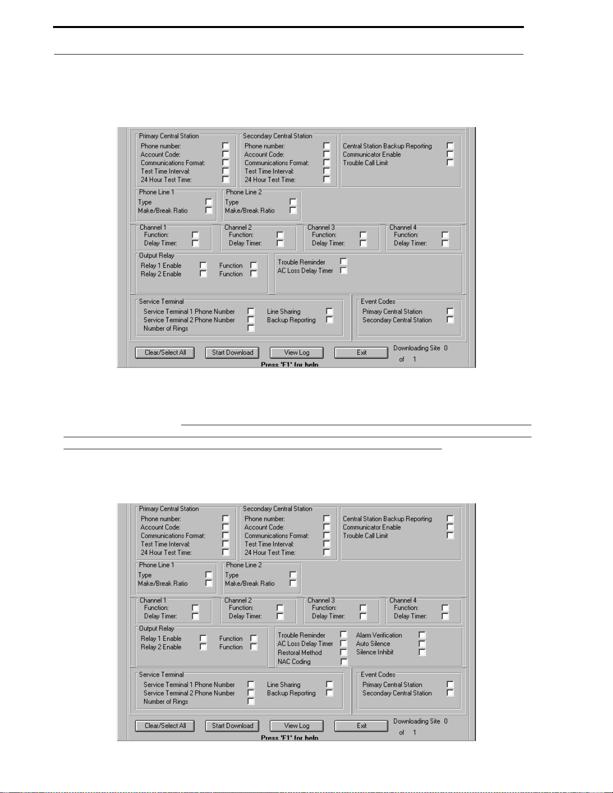
Automatic D o wnloa d
FIGURE 6-14:
Automatic Download Window for the 411UD
It should be noted that, since the Automatic Download feature involves downloading to a series of different digital
communicators, an error or interruption during an y one download will not prevent the downloading t o oth er panels in
the automatic download list. For this reason, it is vita lly important that the
View Log be checked following the com-
pletion of all downloads. The log, which automatically pops-up on completion of the Automatic Download, will list
the results of each download operation, including whether or not the dow nload was successful.
FIGURE 6-15:
Automatic Download Window for the 411UDAC
54
Document #50802 Rev.B 1/5/99 P/N 50802:B
Page 55

Automatic D o wnloa d
Following are examples of when verification of specific program fields may be employed.
New D ig ital Co mmunic a tor Ins t al lati ons o r Complete Reprog rammi ng
Download Without Specif ic Field Verification
- Automatic Download may be accomplished without verifying an y
program fields. This option would be used when programming new digi tal communicators or when changing all
of the programming in existing communicators. Since verification is not being employed, make certain check
marks appear in all fields in the window shown in Figure 6-14 or Figure 6-15. To set all check marks, click the
Clear/Select All button. This button will cause the window to toggle between clearing any check marks found in
the window, and inserting check marks in all fields of a cleared window. Once check marks appear in all fields,
click the Start Download b utton to be gin the do wnload operati on. See “Dow nload to Communicat or” on page 46
for a description of the download operation.
Partial Reprogramming of Existing Digital Communica tors
Download With Specific Field Verification
- Automatic Download may be accomplished with verification of specific program fields. This option would be used when partially reprogramming existing digital communicators.
Place a check mark next to the program field(s) that will be changed by the new program by clicking on the
selected field. Refer to Figure 6-1 4 or Figure 6-15. The Clear/Se lect All button will cause the window to toggle
between clearing any check marks found in the window, and inserting check marks in all fields of a cleared window. Once all desired check marks have been inserted, click the S tart D ownload button to b egin the download
operation. See “Download to Communicator” on page 46, for a description of the download operation.
After downloading has been completed, check the Vie w Lo g to confirm that each download has been successfully
completed. The window shown in Figure 6-16 will appear.
FIGURE 6-16:
View Log
If any file downloads were unsuccessful, a list of errors and failed attempts will be displayed as shown in this
example. This window will also indicate all successful downloads.
Document #50802 Rev. B 1/5/99 P/N 50802:B
55
Page 56
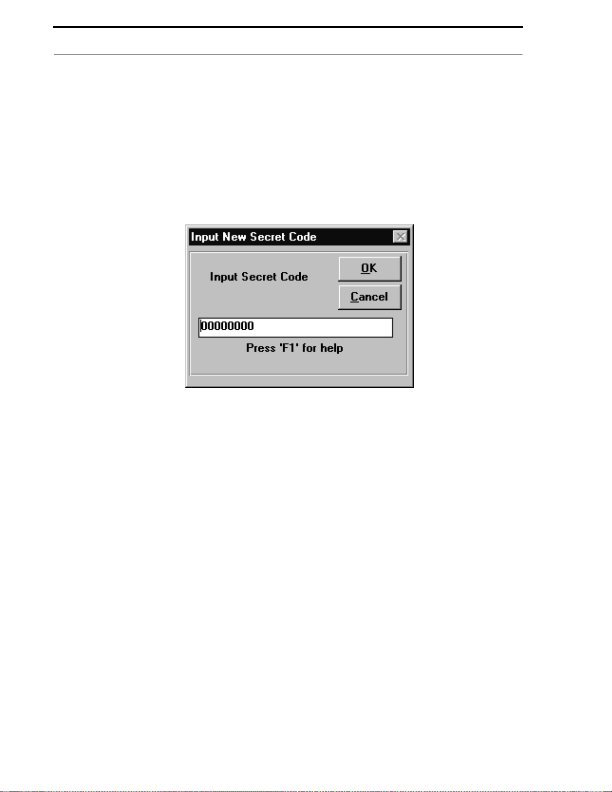
Se cret Code
CHAPTER 7
The Secret Code feature provides protection from unauthorized changes to the digital communicator program. The
factory default Secret Code for all 411UD/411UDAC digital communicators is '00000000', but each communicator
should be customized by the user. The code can only be changed through an initial download to the communicator or
by using the Change Secret Code feature. Clicking the Chang e Se cret Code button in the Main Menu window will
display the window shown in Figure 7-1.
FIGURE 7-1:
Secret Code
Secr et Code
Use this window to change the Secret Code after it has been established by an initial download. Double-click in the
white text block and type from 1 to 8 characters for the new secret code. Click the OK button to begin the Secret
Code download process. For an explanation of the download process and the windows which will appear, refer to
“Download to Communicator” on page 46. Note that only the secret code will b e downloaded during this procedure.
56
Document #50802 Rev.B 1/5/99 P/N 50802:B
Page 57

Utilities - Compa re
CHAPTER 8
The Compare feature allows the user to compare the programmin g of tw o separate prog ram f iles, side-b y-sid e. Clicking the Compar e button in the Main Menu will cause the window shown in Figure 8-1 to appear.
FIGURE 8-1:
Compare
Utilities - Compa re
Program files, that are a v ailable for comparison, can be vie w ed b y clicking the plus (+) signs next to the text Commu-
nicator f or in the two sections of the Compare window. Click all (+) signs until only (-) signs are visible. This will
allow the user to view all available files in each section. Click the first file in the left screen to be compared.
Document #50802 Rev. B 1/5/99 P/N 50802:B
57
Page 58
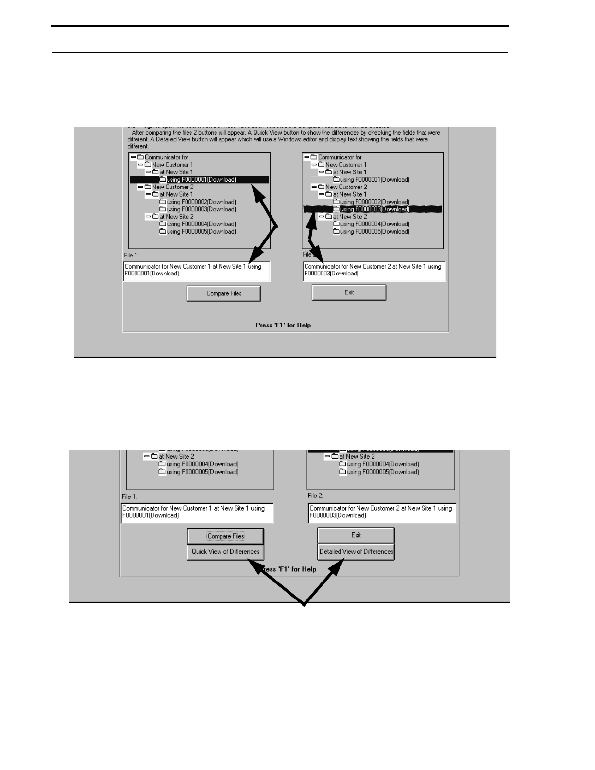
Utilities - Compa re
The filename will appear in the text block labeled Fi l e 1 . Click the second file in the right screen to be compared.
The filename will appear in the text block labeled Fi l e 2 as shown in Figure 8-2.
FIGURE 8-2:
Compa re File Selections
Click the Compare Files button to begin the compare process. The software will search for the program f ields which
differ from one file to the next. The window shown in Figure 8-3 will be displayed.
FIGURE 8-3:
View Comparison
Two buttons appear which allow viewing of the differences between the two program files.
58
Document #50802 Rev.B 1/5/99 P/N 50802:B
Page 59

Quick V iew of Differe nce s
8.1 Quick View of Differences
Clicking the Quick View of Differences button will display the window shown in Figure 8-4.
FIGURE 8-4:
Quick View Compa re
The Quick View window indicates the fields which differ from file to file without specifying the actual differences. A check mark, in the box next to the field, indicates that field contains different information in the two
files being compared.
Document #50802 Rev. B 1/5/99 P/N 50802:B
59
Page 60
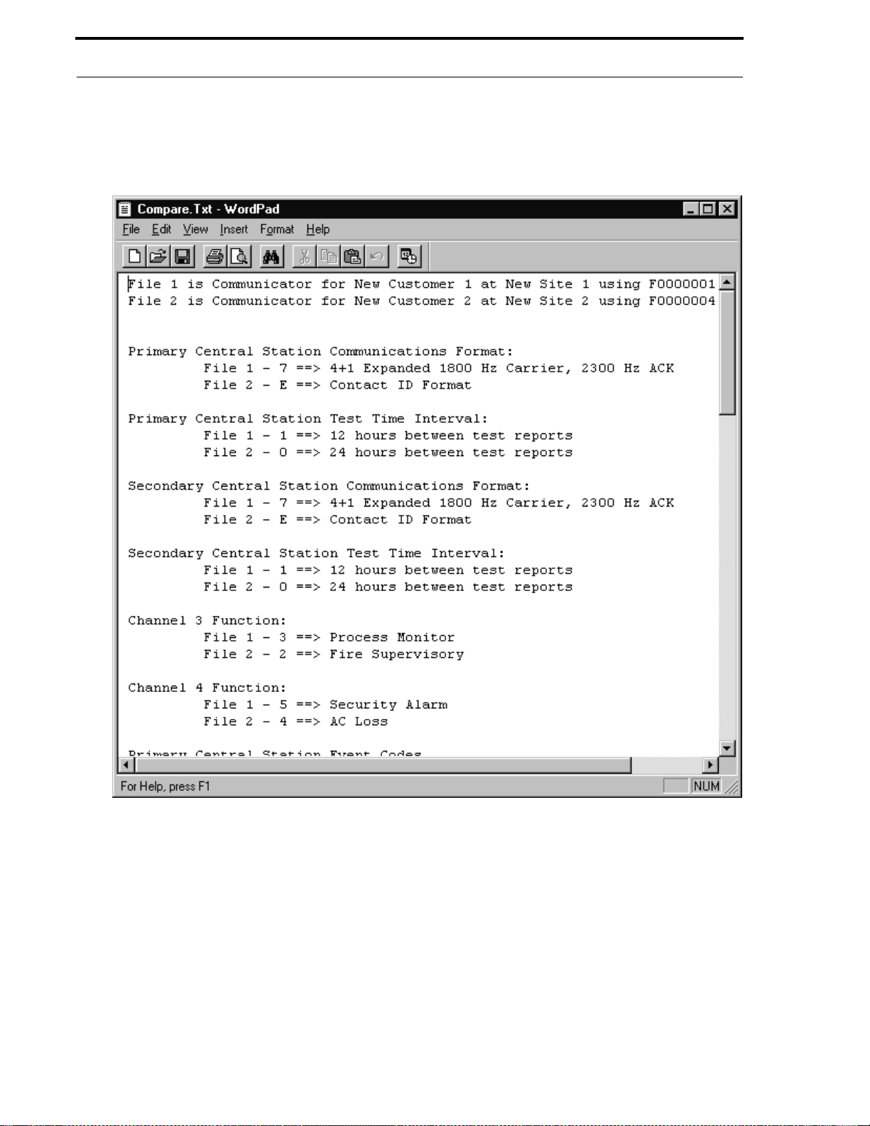
Detailed View of Differences
8.2 Detailed View of Differences
Clicking the Detailed View of Differences button will display the window shown in Figure 8-5.
FIGURE 8-5:
Detailed View of Compare
60
The Detailed View window is a Wordpad text window that displays the specific differences between the two files
being compared. A field-by-field comparison is provided between the first program file and the second file. A
printout of this screen is available by clicking File and clicking Print in the File menu.
Document #50802 Rev.B 1/5/99 P/N 50802:B
Page 61
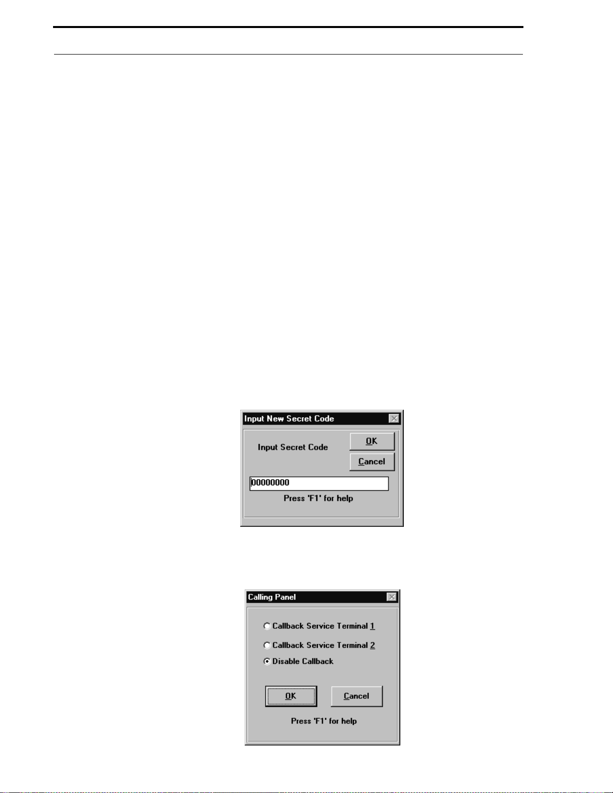
Security Features
CHAPTER 9
Security features have been incorporated into the PK-411UD software to maximize digital communicator integrity
and reliability. These features include the following:
✓ restricted access to the program
✓ communicator callback to service terminal
✓ digital communicator time-out
✓ data error checking
✓ central station acknowledge
✓ central station data protection
Secur ity Fea tures
9.1 Secret Code
The Secret Code for each 411UD/411UDAC digital communicator is set to a factory default value of 00000000 . The
Secret Code for each communicator should be customized by the PK-411UD user. The code can only be changed
through an initial download to the communicator or by using the Change Secret Code feat ure.
To change the Secret Code after it has been established by an initial download, select Change Secret Code from the
Main Menu. Clicking the Change Secret Code button will cause the window shown in Figure 9-1 to be displayed.
A flashing cursor will be positioned in the box at the bottom of the window.
FIGURE 9-1:
Type from 1 to 8 characters for the new Secret Code. Use the mouse arrow to click the OK button. The window
shown in Figure 9-2 will be displayed.
FIGURE 9-2:
Secret Code
D own loading S ecret Code
Document #50802 Rev. B 1/5/99 P/N 50802:B
61
Page 62

Pa ne l C a llba ck
Select one of the three options:
✓ Callback Service Terminal 1
✓ Callback Service Terminal 2
✓ Disable Callback
Once the selection has been made, click the
The Customer File is automatically updated with the new Secret Code.
button to download the ne w Secret code to the digital communicator.
9.2 Panel Callback
Upload or download operations may require the digital communicator to callback the service termi nal initiating the
call, before proceeding with a data transfer. Note that 'Disable Callback' may be selected by the master operator,
which will allow the operator to complete an upload/download from any service terminal location. This callback procedure is incorporated into the software for the following reasons:
✓ Confirmation of service terminal initiating call
✓ Insures that only authorized service terminal can access the digital communicator
✓ Digital communicator must notify the central station(s) of request for upload or download. If central
station(s) denies the request, the communicat or will not callback the service terminal
9 .3 D igital C omm unicator T ime- out
The 411UD/411UDAC software has been designed to terminate communications with a service terminal if valid data
is not received within a specific period of time. Reasons for the termination are as follows:
• If the modem connect sequence does not occur within 30 seconds of the digital communicator answering a
call, the communicator will terminate (hangup) the call. This is a protection against wrong numbers interfering with normal digital communicator operations
• Following the connection of the digital communicator and service terminal modem, any errors occurring during message or data transfers will prompt an attempt to retransmit the information. If transmission errors continue with each retry, the communicator will terminate the call after 2 minutes
• Following the connection of the communicator and service terminal modem, any delay of 2 minutes or more
in initiating a data transfer will result in the communicator terminating the call
• After answering a call from service terminal, the communicator will attempt to callback the service terminal a
maximum of 4 times (Callback Service Terminal enabled). If the Secret Code is not verified after the 4th
attempt, the communicator will hangup and notify the Central Station(s) of the failed upload/download
attempt. Possible reasons for failure of the service terminal to answer a callback are as follows:
✓ Service terminal phone line inoperative
✓ Service terminal modem failure
✓ Service terminal window initiating call has been exited before receiving callback
✓ Data transmission errors have occurred prompting up to a 2 minute time-out. 4 callbacks have been
made, each resulting in up to a 2 minute time-out.
62
Document #50802 Rev.B 1/5/99 P/N 50802:B
Page 63

Error Checking
9 .4 E rror Checking
Data from the service terminal is transmitted to a temporary holding buffer in the digital communicator. This data is
verified by the communicator for integrity and if the data is correct, it will be transferred from the temporary b uf fer to
the communicator memory for permanent storage and immediate use.
If the data is found to be incorrect, the digital communicator will request the service terminal to retransmit the data.
If the retransmitted data is still incorrect, the communicator will continue to request retransmission for a maximum of
2 minutes. If still unsuccessful, the communicator will terminate the connection. Should a failure to transmit occur,
the operator must reinitiate the sequence at the service terminal.
9.5 Central Station Acknowledge
The digital communicator will report to the Central Station(s) that a request for upload or download has been
received. If the Central Station(s) does not acknowledge receipt of this request, uploading or downloading is prohibited. If acknowledged by the Central Station(s), another message is transmitted by the digital communicator informing the Central Station(s) that:
• downloading was successful
• uploading was successful
• uploading/downloading was not successful
9 . 6 Password P rotection
The PK-411UD provides four user access levels, each requiring a password for access. Refer to “Operator” on page
16, for a description about this process.
• Level 0 is reserved for the Master(s). All PK-411UD option s are a v ailable to the Master. In addition, the Master must assign all other levels and their passwords and may view Operator Information
• Level 1 has access to all options except the assignment of level access and passwords and Level 1 cannot disable Central Station callback. A Level 1 user can view only their own Operator information and can change
only their own password
• Level 2 can upload from the digital communicator, view the upload data, print the upload and download data,
change the modem configuration and vie w the down load data but not edit and sav e it. A Lev el 2 user can view
only their own Operator information and can change only their own password
• Level 3 can on ly view and print the upload data. A Le vel 3 user can vie w only their o wn Operato r informatio n
and can change only their own password
Document #50802 Rev. B 1/5/99 P/N 50802:B
63
Page 64

Notes
64
Document #50802 Rev.B 1/5/99 P/N 50802:B
Page 65

Index
Numerics
411UD 6, 34, 35, 44
411UDAC 6, 36, 37, 38, 39, 44, 45
A
AC Loss Delay Timer 34, 35, 36, 38
Access Level 17
017
117
217
317
Account Code 32
Alarm Verification 36
Auto Silence 36, 38
Auto-Detect
see Communication Port
Automatic Download 44, 53
411UD 54
411UDAC 54
Automatic Download List 43
B
Backup Reporting 33
Baud Rate 10, 23
C
Callback 7, 46, 48
Callback Panel 62
Centering Windows 14
Central Station 33
Backup Reporting 33
Central Station Acknowledge 7, 63
Central Station Programming 31
Service Terminal Phone Number 31
Valid entries 31
Change Directory 12
Channel Function 37
Communication Port 23
Auto-Detect 23
Communications 46
Communications Format 32
Communicator Disable 33
Communicator Selection 15
Communicator Time 52
Compare Files 57, 58
Detailed V iew 60
Quick View 59
View 58
Complete Reprogramming 55
Configure Modem 10
Controller 33
Converting Upload File to Download File 49
Copyright Window 14
Current Information 51
Customer
Add Site Information 27
Add to Database 25, 26
Button 25
Delete from Database 26
Delete Site Information 27
Information 25
Print Files 29
Customer File Utility 6
Customer Files Window 29
D
Data Entry 24
Default Directory 19
Default Directory and File 18
default path 12
Delay Timer 34, 37
Description of PK -411UD 6
Download
with Callback 47
without Callback 47
Download File Utility 6
Download to Communicator 46
E
Error Checking 7, 63
Escape 7, 8
Recall 7
Event Code Programming 40
Event Codes 40
F
Features of PK-411UD 6
File Compare Utility 7
Filename Extension 28
Filename Selection 50
H
Hangup String 23
Help 7, 8
On-line 8
I
Initialization 14
Initialization String 22
Input/Output Programming 34, 36
Install Directory 19
Installation 11
Using Windows® 11
K
Keyboard Operation 14
L
Line Shared 42
Log-in 15
M
Master 17
Master Operator 14
Memory 9
Microprocessor 9
Modem 6, 22
Baud Rate 10
Communication Port 23
Configure 10, 21
Connections 11
External 10, 11
Hangup String 22, 23
Initialization String 22
Internal 10, 11
Saving Settings 23
Modem Testing
AT Test Command 23
Dial Button 2 3
Hangup Button 23
Initialize Button 23
Modems 10
Compatible 10
Modified Fields 44
Monitor 9
Mouse 9
Document #50802 Rev. B 1/5/99 P/N 50802:B
65
Page 66

N
NAC Coding 36, 39
Number of Rings 42
O
Operating System 6, 8
Operator 17
Operator Identification Utility 6
Operator Setup 16
Output Relay 37
Output Relay Programming 35
Modem 16
Operator 16
Silence Inhibit 36
Slave Communicator 33
Software Registration 14
System Requirements 9
Environment 9
Memory 9
Microprocessor 9
Monitor 9
Mouse 9
P
Panel Identification Number 7
Partial Reprogramming 55
Password 6, 14, 15, 63
Access Level 17
Level 0 63
Level 1 63
Level 2 63
Level 3 63
Operator 14
Phone System
Rotary 32
Make/Break Ratio 32
Touch Ton e 32
Print Option 30
Print Options 29
Print Utility 7
Program
Current Information 28
Factory Default 28
User Default 28
Program File
Add to Database 27
Program Files 13
Customizing 31
Off-line 13
On-line 13
Programming 6
Programming Utility 6
Installation 11
Installation Prompts 12
Inventory 11
Run Upload/Download P rogram 14
T
Test 33
Test Ti me 32
Test Time Interval 32
Time-out 7, 62
Transfers 49
Trouble Call Limit 33
Trouble Reminder 34, 35, 36
Troubleshoot 7, 52
411UD 52
411UDAC 53
U
Upload File Utility 7
Upload from Communicator 48
User Default File 20
V
View Log 55
W
Windows® 11
R
Recall 7, 8, 50, 51
Record Count 17, 18
Restoral Method 36, 39
Retries 49
Ring Duration 42
RJ11 Jack 11
S
Secret Code 7, 56, 61
Change 56, 61
Security Features 7, 61
Central Station Acknow ledg e 63
Digital Communicator Time-out 62
Error Checking 63
Panel Callback 62
Password Protection 63
Secret Code 61
Service Terminal 41, 42
Service Terminal Programming 41
Setup 1 6
Default Directory and File 16
66
Document #50802 Rev.B 1/5/99 P/N 50802:B
Page 67

Notes
Document #50802 Rev. B 1/5/99 P/N 50802:B
67
Page 68

Limite d Warranty
Fire•Lite® warrants its products to be free from defects in materials and
workmanship for eighteen (18) months from the date of manufacture, under
normal use and service. Products are date stamped at time of
manufacture. The sole and exclusive obligation of Fire•Lite
replace, at its option, fre e of charge for part s and labor, any part which is
defective in materials or wor kmanship u nder nor mal use a nd ser vice. For
®
products not under Fire•Lite
manufacturing date-stamp control, the war-
ranty is eighteen (18) months from date of original purchase by Fire•Lite®'s
distributor unless the installation instru ct io ns or catalog sets forth a shorter
period, in which case the shorter period shall apply. This warranty is void if
the product is altered, repaired or serviced by anyone other than Fire•Lite
or its authorized d istributors or if t here is a failure to m aintain the prod ucts
and systems in whi ch they operate in a prope r and workable manner. In
case of defect, secure a Return Material Authorization form from our
customer service department. Return pr oduct, transportation prepaid, to:
®
Fire•Lite
, One Fire-Lite Place, Northford, Connecticut 06472-1653.
This writing constitutes th e only warranty made by Fire•Lite
to this products. Fire•Lite® does not represent that its products will prevent
any loss by fire or otherwise, or that its products will in all cases provide the
protection for which they are installed or intended. Buyer acknowledges
®
that Fire•Lite
is not an insure r and ass umes no r isk for loss or damag es
or the cost of any inconvenience, transpor tation, dama ge, misuse, abuse,
accident or similar incident.
®
is to repair or
®
with respect
®
Fire•Lite® GIVES NO WARRANTY, EXPRESSED OR IMPLIED, OF
MERCHANTABILITY, FITNESS FOR ANY PARTICULAR PUR POSE, OR
OTHERWISE WHICH EXTEND BEYOND THE DESCRIPTION ON THE
®
FACE HEREOF. UNDER NO CIRCUMSTANCES SHALL Fire•Lite
BE
LIABLE FOR ANY LOSS OF OR DAMAGE TO PROPERTY, DIRECT,
INCIDENTAL OR CONSEQUENTIAL, ARISING OUT OF THE USE OF OR
®
INABILITY TO USE Fire•Lite
PRODUCTS. FURTHERMORE, Fire•Lite
SHALL NOT BE LIABLE FOR ANY PERSONAL INJURY OR DEATH
WHICH MAY ARISE IN THE COURSE OF, OR AS A RESULT OF,
PERSONAL, COMMERCIAL OR INDUSTRIAL USE OF ITS PRODUCTS.
This warranty replaces all previous warranties and is the only warranty
®
made by Fire•Lite
. No increase or alteration, written or verbal, of the obli-
gation of this warranty is authori zed
Fire•Lite
®
is a registered trademark.
One Fire-Lite Place
Northford, CT 06472
Phone: (203) 484-7161
FAX: (203) 484-7118
®
 Loading...