

Page 1

PN: 51899:B1 ECN 05-044
Digital Alarm Communicator/Transmitter
DACT-UD Module
Document #51899
B
1/25/05 Revision:
1
Page 2

Fire Alarm System Limitations
While a fire alarm system may lower insurance
rates, it is not a substitute for fire insurance!
An automatic fire alarm system–typically made up of smoke
detectors, heat detectors, manual pull stations, audible warning devices, and a fire alarm control with remote notification
capability–can provide early warning of a developing fire.
Such a system, however, does not assure protection against
property damage or loss of life resulting from a fire.
The Manufacturer recommends that smoke and/or heat detectors be located throughout a protected premise following the
recommendations of the current edition of the National Fire
Protection Association Standard 72 (NFPA 72),
manufacturer's recommendations, State and local codes, and
the recommendations contained in the Guide for Proper Use
of System Smoke Detectors, which is made available at no
charge to all installing dealers. A study by the Federal Emergency Management Agency (an agency of the United States
government) indicated that smoke detectors may not go off in
as many as 35% of all fires. While fire alarm systems are designed to provide early warning against fire, they do not guarantee warning or protection against fire. A fire alarm system
may not provide timely or adequate warning, or simply may not
function, for a variety of reasons:
Smoke detectors may not sense fire where smoke cannot
reach the detectors such as in chimneys, in or behind walls, on
roofs, or on the other side of closed doors. Smoke detectors
also may not sense a fire on another level or floor of a building. A second-floor detector, for example, may not sense a
first-floor or basement fire.
Particles of combustion or "smoke" from a developing fire
may not reach the sensing chambers of smoke detectors because:
• Barriers such as closed or partially closed doors, walls, or
chimneys may inhibit particle or smoke flow.
• Smoke particles may become "cold," stratify, and not reach
the ceiling or upper walls where detectors are located.
• Smoke particles may be blown away from detectors by air
outlets.
• Smoke particles may be drawn into air returns before reaching
the detector.
The amount of "smoke" present may be insufficient to alarm
smoke detectors. Smoke detectors are designed to alarm at
various levels of smoke density. If such density levels are not
created by a developing fire at the location of detectors, the
detectors will not go into alarm.
Smoke detectors, even when working properly, have sensing
limitations. Detectors that have photoelectronic sensing
chambers tend to detect smoldering fires better than flaming
fires, which have little visible smoke. Detectors that have ionizing-type sensing chambers tend to detect fast-flaming fires
better than smoldering fires. Because fires develop in different ways and are often unpredictable in their growth, neither
type of detector is necessarily best and a given type of detector may not provide adequate warning of a fire.
Smoke detectors cannot be expected to provide adequate
warning of fires caused by arson, children playing with
matches (especially in bedrooms), smoking in bed, and violent
explosions (caused by escaping gas, improper storage of
flammable materials, etc.).
Heat detectors do not sense particles of combustion and alarm
only when heat on their sensors increases at a predetermined
rate or reaches a predetermined level. Rate-of-rise heat detectors may be subject to reduced sensitivity over time. For this
reason, the rate-of-rise feature of each detector should be tested
at least once per year by a qualified fire protection specialist.
Heat detectors are designed to protect property, not life.
IMPORTANT! Smoke detectors must be installed in the
same room as the control panel and in rooms used by the
system for the connection of alarm transmission wiring, communications, signaling, and/or power. If detectors are not so
located, a developing fire may damage the alarm system,
crippling its ability to report a fire.
Audible warning devices such as bells may not alert people
if these devices are located on the other side of closed or
partly open doors or are located on another floor of a building.
Any warning device may fail to alert people with a disability or
those who have recently consumed drugs, alcohol or medication. Please note that:
• Strobes can, under certain circumstances, cause seizures
in people with conditions such as epilepsy.
• Studies have shown that certain people, even when they
hear a fire alarm signal, do not respond or comprehend the
meaning of the signal. It is the property owner's responsibility to conduct fire drills and other training exercise to
make people aware of fire alarm signals and instruct them
on the proper reaction to alarm signals.
• In rare instances, the sounding of a warning device can
cause temporary or permanent hearing loss.
A fire alarm system will not operate without any electrical
power. If AC power fails, the system will operate from standby
batteries only for a specified time and only if the batteries
have been properly maintained and replaced regularly.
Equipment used in the system may not be technically compatible with the control. It is essential to use only equipment
listed for service with your control panel.
Telephone lines needed to transmit alarm signals from a
premise to a central monitoring station may be out of service
or temporarily disabled. For added protection against telephone line failure, backup radio transmission systems are recommended.
The most common cause of fire alarm malfunction is inadequate maintenance. To keep the entire fire alarm system in
excellent working order, ongoing maintenance is required per
the manufacturer's recommendations, and UL and NFPA standards. At a minimum, the requirements of NFPA 72 shall be
followed. Environments with large amounts of dust, dirt or
high air velocity require more frequent maintenance. A maintenance agreement should be arranged through the local
manufacturer's representative. Maintenance should be
scheduled monthly or as required by National and/or local
fire codes and should be performed by authorized professional fire alarm installers only. Adequate written records of
all inspections should be kept.
PrecauLarge.PMD 01/10/2005
Page 3

Installation Precautions
Adherence to the following will aid in problem-free
installation with long-term reliability:
WARNING - Several different sources of power can be con-
nected to the fire alarm control panel. Disconnect all sources
of power before servicing. Control unit and associated equipment may be damaged by removing and/or inserting cards,
modules, or interconnecting cables while the unit is energized.
Do not attempt to install, service, or operate this unit until this
manual is read and understood.
CAUTION - System Reacceptance Test after Software
Changes. To ensure proper system operation, this product
must be tested in accordance with NFPA 72 after any programming operation or change in site-specific software. Reacceptance testing is required after any change, addition or
deletion of system components, or after any modification,
repair or adjustment to system hardware or wiring.
All components, circuits, system operations, or software functions known to be affected by a change must be 100% tested.
In addition, to ensure that other operations are not inadvertently affected, at least 10% of initiating devices that are not
directly affected by the change, up to a maximum of 50 devices, must also be tested and proper system operation verified.
This system meets NFPA requirements for indoor dry operation at 0-49° C/32-120° F
RH (non-condensing) at 32 ±2° C/90 ±3° F. However, the
useful life of the system's standby batteries and the electronic components may be adversely affected by extreme
temperature ranges and humidity. Therefore, it is recommended that this system and all peripherals be installed in
an environment with a nominal room temperature of 15-27°
C/60-80° F.
Verify that wire sizes are adequate for all initiating and
indicating device loops. Most devices cannot tolerate more
than a 10% I.R. drop from the specified device voltage.
and at a relative humidity of 93 ±2%
Like all solid state electronic devices, this system may
operate erratically or can be damaged when subjected to
lightning-induced transients. Although no system is completely immune from lightning transients and interferences,
proper grounding will reduce susceptibility. Overhead or out-
side aerial wiring is not recommended, due to an increased
susceptibility to nearby lightning strikes. Consult with the
Technical Services Department if any problems are anticipated or encountered.
Disconnect AC power and batteries prior to removing or inserting circuit boards. Failure to do so can damage circuits.
Remove all electronic assemblies prior to any drilling, filing,
reaming, or punching of the enclosure. When possible, make
all cable entries from the sides or rear. Before making modifications, verify that they will not interfere with battery, transformer, and printed circuit board location.
Do not tighten screw terminals more than 9 in-lbs.
Over-tightening may damage threads, resulting in reduced
terminal contact pressure and difficulty with screw terminal
removal.
Though designed to last many years, system components
can fail at any time. This system contains static-sensitive
components. Always ground yourself with a proper wrist strap
before handling any circuits so that static charges are removed from the body. Use static-suppressive packaging
to protect electronic assemblies removed from the unit.
Follow the instructions in the installation, operating, and
programming manuals. These instructions must be followed
to avoid damage to the control panel and associated
equipment. FACP operation and reliability depend upon
proper installation by authorized personnel.
FCC Warning
WARNING: This equipment generates, uses, and can ra-
diate radio frequency energy and if not installed and used
in accordance with the instruction manual, may cause interference to radio communications. It has been tested
and found to comply with the limits for class A computing
device pursuant to Subpart B of Part 15 of FCC Rules,
which is designed to provide reasonable protection against
such interference when operated in a commercial environment. Operation of this equipment in a residential area is
likely to cause interference, in which case the user will be
required to correct the interference at his own expense.
PrecauLarge.PMD 01/10/2005
Canadian Requirements
This digital apparatus does not exceed the Class A
limits for radiation noise emissions from digital
apparatus set out in the Radio Interference Regulations
of the Canadian Department of Communications.
Le present appareil numerique n'emet pas de bruits
radioelectriques depassant les limites applicables aux
appareils numeriques de la classe A prescrites dans le
Reglement sur le brouillage radioelectrique edicte par le
ministere des Communications du Canada.
Page 4

Notes
4 DACT-UD PN 51899:B1 1/25/05
Page 5

Table of Contents
SECTION 1: Product Description ........................................................................................................................8
1.1: Product Features..........................................................................................................................................8
1.2: Compatible Panel ........................................................................................................................................8
1.3: Specifications ..............................................................................................................................................8
1.4: Digital Communicator.................................................................................................................................9
1.5: Telephone Requirements and Warnings ......................................................................................................10
1.5.1: Telephone Circuitry - PH1 & PH2....................................................................................................10
1.5.2: Digital Communicator.......................................................................................................................10
1.5.3: Telephone Company Rights and Warnings.......................................................................................11
SECTION 2: DACT-UD Installation ....................................................................................................................13
2.1: Installation in MS-9600 FACP....................................................................................................................13
2.1.1: MS-9600 Keypad/Display Removal .................................................................................................13
2.1.2: DACT-UD Installation ......................................................................................................................14
SECTION 3: Programming for DACT-UD .........................................................................................................17
3.1: Programming the MS-9600 Fire Alarm Control Panel ...............................................................................17
3.1.1: On-Board DACT...............................................................................................................................17
3.1.1.1 DACT-UD Enable ...................................................................................................................17
3.1.1.2 Primary Phone .........................................................................................................................18
3.1.1.3 Secondary Phone .....................................................................................................................18
3.1.1.4 Service Terminal .....................................................................................................................19
3.1.1.4.1 Panel ID ................................................................................................................................19
3.1.1.4.2 Terminal 1 and Terminal 2 ...................................................................................................20
3.1.1.4.3 Ring Count ...........................................................................................................................21
3.1.1.5 Central Station .........................................................................................................................21
3.1.1.5.1 Reporting Enable ..................................................................................................................21
3.1.1.5.2 Backup Reporting ................................................................................................................22
3.1.1.5.3 Trouble Call Limit (Dialer Runaway Prevention) ...............................................................22
3.1.1.5.4 Central Station Primary and Secondary Phone Numbers ....................................................23
3.1.1.6 Manual Dial Mode ..................................................................................................................35
3.2: Remote Site Upload/Download...................................................................................................................36
3.2.1: Downloading Program: General .......................................................................................................36
3.2.2: Security Features...............................................................................................................................37
3.3: Downloading Initiated at a Service Terminal..............................................................................................39
3.4: Uploading Initiated at a Service Terminal...................................................................................................39
3.5: Simultaneous Data Transfers.......................................................................................................................40
SECTION 4: Central Station Communications ..................................................................................................41
4.1: Transmittal Priorities...................................................................................................................................44
APPENDIX A: Default Programming .................................................................................................................46
APPENDIX B: Ademco Contact ID Format
...................................................................................................................................................................................
Event Code Descriptions ........................................................................................................................................47
APPENDIX C: Central Station Points ................................................................................................................52
DACT-UD P/N: 51889:B1 1/25/05 5
Page 6

Notes
6 DACT-UD PN 51899:B1 1/25/05
Page 7
It is imperative that the installer understand the requirements of the Authority Having Jurisdiction
(AHJ) and be familiar with the standards set forth by the following regulatory agencies:
• Underwriters Laboratories Standards
• NFPA 72 National Fire Alarm Code
Before proceeding, the installer should be familiar with the following documents.
NFPA Standards
NFPA 72 National Fire Alarm Code
• Central Station Fire Alarm Systems (Automatic, Manual and Waterflow) Protected
Premises Unit
• Local (Automatic, Manual, Waterflow and Sprinkler Supervisory) Fire Alarm
Systems
• Proprietary Fire Alarm Systems (Protected Premises Unit)
NFPA 70 National Electrical Code
Underwriters Laboratories Documents:
UL 38 Manually Actuated Signaling Boxes
UL 217 Smoke Detectors, Single and Multiple Station
UL 228 Door Closers–Holders for Fire Protective Signaling Systems
UL 268 Smoke Detectors for Fire Protective Signaling Systems
UL 268A Smoke Detectors for Duct Applications
UL 346 Waterflow Indicators for Fire Protective Signaling Systems
UL 464 Audible Signaling Appliances
UL 521 Heat Detectors for Fire Protective Signaling Systems
UL 864 Standard for Control Units for Fire Protective Signaling Systems
UL 1481 Power Supplies for Fire Protective Signaling Systems
UL 1610 Central Station Burglar Alarm Units
UL 1638 Visual Signaling Appliances
UL 1971 Signaling Devices for Hearing Impaired
Other:
EIA-232E Serial Interface Standard
EIA-485 Serial Interface Standard
NEC Article 250 Grounding
NEC Article 300 Wiring Methods
NEC Article 760 Fire Protective Signaling Systems
Applicable Local and State Building Codes
Requirements of the Local Authority Having Jurisdiction (LAHJ)
Fire-Lite Documents:
Fire-Lite Device Compatibility Document #15384
MS-9600 Manual Document #51335
DACT-UD PN 51899:B1 1/25/05 7
Page 8

Product Description Product Features
SECTION 1 Product Description
The DACT-UD Digital Alarm Communicator/Transmitter transmits system status to
UL listed Central Station Receivers via the public switched telephone network. The
communicator mounts to the FACP main circuit board inside the panel cabinet and is
capable of reporting 636 points or 99 zones.
1.1 Product Features
• Dual telephone lines
• Dual telephone line voltage detect
• Mounts inside the control panel
• Extensive transient protection
• Individual LEDs for
Kissoff - green LED
Primary Phone Line Active - red LED
Secondary Phone Line Active - red LED
• Communicates vital system status including:
Independent zone/point alarm
Independent zone/point trouble
Independent zone/point supervisory
AC power loss
Low battery
Earth fault
System off normal
12 or 24 hour test signal
Abnormal test signal per UL requirements
Annunciation at control panel of DACT troubles including loss of phone lines,
communication failure with either Central Station, total communication failure
1.2 Compatible Panel
The DACT-UD has been designed to be compatible with the following control panel:
• MS-9600
1.3 Specifications
DC Power - J1 Connector
Current draw in standby and alarm:
Standby = 0.100 amps
Alarm = 0.132 amps (communicating)
8 DACT-UD PN 51899:B1 1/25/05
Page 9

Digital Communicator Product Description
1.4 Digital Communicator
Two modular phone jacks allow easy connection to telephone lines. Modular jacks are
labeled PH1 and PH2 for the Primary and Secondary phone lines. Telephone line
Primary Active and Secondary Active red LEDs are provided as well as a green Kissoff
LED> The digital communicator provides the following functions:
• Line Seizure - takes control of phone lines disconnecting any premises phones
• Off/On Hook - performs on and off-hook status to the phone lines
• Listen for dial tone - 440 hertz tone typical in most networks
• Dialing Central Station(s) number - default is Touch-Tone®, programmable to
rotary
• For tone burst or touchtone type formats: determine proper ‘Acknowledge’ and
‘Kissoff’ tone(s) - the frequency and time duration of the tone(s) varies with the
transmission format. The control panel will adjust accordingly
• Communicate in the following formats:
12 Tone Burst Types: 20 pps
(3+1, 4+1, 4+2, 3+1 Exp., 4+1 Exp., 4+2 Exp.)
3 Touchtone Types:
4+1 Ademco Express
4+2 Ademco Express
Ademco Contact ID
DACT-UD PN 51899:B1 1/25/05 9
Page 10

Product Description Telephone Requirements and Warnings
1.5 Telephone Requirements and Warnings
1.5.1 Telephone Circuitry - PH1 & PH2
Ringer Equivalence Number (REN) = 0.0B
AC Impedance: 10.0 Mega Ohm
Complies with FCC Part 68
Mates with RJ31X Male Connector
Supervision Threshold: less than 4.0 volts for 2 minutes
The REN is used to determine the quantity of devices which may be connected to
the telephone line. Excessive RENs on the telephone line may result in the devices
not ringing in response to an incoming call. In most, but not all areas, the sum of
the RENs should not exceed five (5.0). To be certain of the number of devices that
may be connected to the line, as determined by the total RENs, contact the
telephone company to determine the maximum REN for the calling area.
1.5.2 Digital Communicator
Before connecting the control panel to the public switched telephone network, the
installation of two RJ31X jacks is necessary. If trouble is experienced with this equipment, for repair or warranty information, please contact:
Manufacturer: Fire•Lite Alarms, Inc.
One Fire-Lite Place
Northford, CT 06472
(203) 484-7161
Product Model Number: DACT-UD
FCC Registration Number: US:1W6AL00BDACTUD
Ringer Equivalence: 0.0B
Note: This equipment complies with Part 68 of the FCC rules and the
requirements adopted by the ACTA. On the DACT-UD module IC is a
label that contains, among other information, a product identifier in the
format US:AAAEQ##TXXXX. If requested, this number must be
provided to the telephone company.
Alarm dialing equipment must be able to seize the telephone line and place a call in an
emergency situation. It must be able to do this even if other equipment (telephone,
answering system, computer modem, etc.) already has the telephone line in use. To do
so, alarm dialing equipment must be connected to a properly installed RJ31X jack that
is electrically in series with and ahead of all other equipment attached to the same
telephone line. If there are any questions concerning these instructions, consult the
telephone company or a qualified installer about installing the RJ31X jack and alarm
dialing equipment. Refer to Figure 2.6 on page 16 for an illustration of the proper
installation of this equipment.
10 DACT-UD PN 51899:B1 1/25/05
Page 11

Telephone Requirements and Warnings Product Description
1.5.3 Telephone Company Rights and Warnings
The telephone company, under certain circumstances, may temporarily discontinue
services and/or make changes in its facilities, services, equipment or procedures which
may affect the operation of this control panel. However, the telephone company is
required to give advance notice of such changes or interruptions.
If the control panel causes harm to the telephone network, the telephone company
reserves the right to temporarili discontinue service. Advance notification will be
provided except in cases when advance notice is not practical. In such cases, notification will be provided as soon as possible. The opportunity will be given to correct any
problems and to file a complaint with the FCC if you believe it is necessary.
DO NOT CONNECT THIS PRODUCT TO COIN TELEPHONE, GROUND START, OR
PARTY LINE SERVICES.
When the control panel activates, premise phones will be disconnected.
Two separate phone lines are required. Do not connect both telephone interfaces to the
same telephone line.
The control panel must be connected to the public switched telephone network
upstream (as first device) of any private telephone system at the protected premises.
A plug and jack used to connect this equipment to the premises wiring and telephone
network must comply with the applicable FCC Part 68 rules and requirements adopted
by ACTA. This equipment is designed to be connected to the telephone network or premises wiring using a compliant RJ31X male modular plug and compatible modular
jack that is also compliant.
DACT-UD PN 51899:B1 1/25/05 11
Page 12

Notes
This Page Left Intentionally Blank
12 DACT-UD PN 51899:B1 1/25/05
Page 13
Installation in MS-9600 FACP DACT-UD Installation
A
SECTION 2 DACT-UD Installation
2.1 Installation in MS-9600 FACP
WARNING! Disconnect all sources of power (AC and DC) before installing or
removing any modules or wiring.
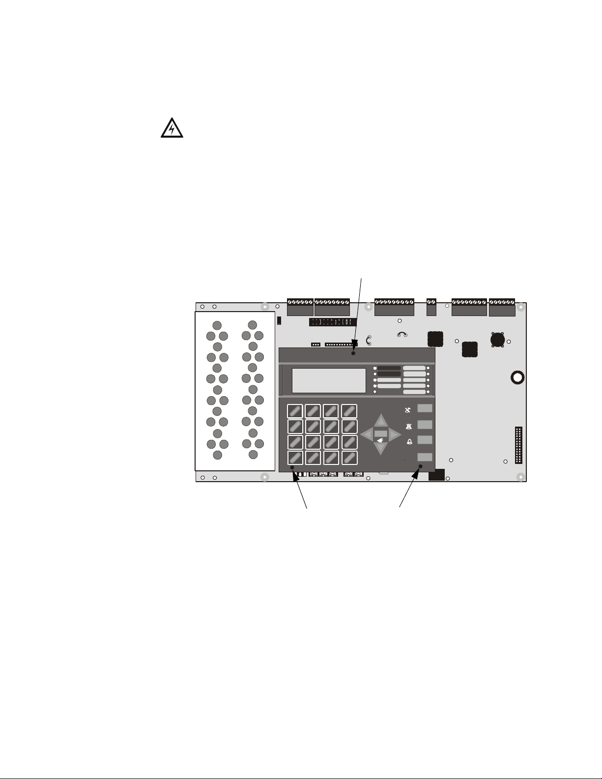
2.1.1 MS-9600 Keypad/Display Removal
DACT-UD (Digital Alarm Communicator/Transmitter) Module installation requires the
removal of the MS-9600 Keypad/Display unit from the main circuit board. To remove
the Keypad/Display, insert a Phillips screwdriver into each of the three holes located in
the flexible covering of the Keypad/Display and loosen the three mounting screws.
Note that it is not necessary to disconnect the cables between the Keypad/Display and
the main circuit board. Carefully lift the Keypad/Display and rest the unit at the bottom
of the main circuit board.
Mounting Screw Access Hole
TB3
JP3
REMOVE
TO DISABLE
LOCAL
CHARGER
JP10
JP2
2
1
DISABL E
GND
FLT
4
5
GHI JKL
J17
J16
78 9
PRS
0
*
QZ
RECALL
HOT
CB1
4XTM OPT BD
ABC DEF
CUT TO
MONITOR 4XTM
TUV WXY
LCD DISPLAY
NEUT E ARTH
TB4 TB5
JP6
AC POWER
FIRE ALARM
SUPERVISORY
st
3
1
JP8
EVENT
JP7
CLR
6
MNO
JP6
ESC
MODE
#
TB1
-/.
+BATTERY-
TB2
ENTER
J6
KEYPAD I/F
TROUBLE
J2
OPT DACT
J8
CK/STEP
ALARM
SILENCE
JP5
MAINTENANCE
ALARM
SILENCED
DISABLED
BATTERY
GROUND
DRILL
HOLD 2 SEC
RESET
Mounting Screw Access Holes
Figure 2.1 Keypad/Display Removal
TB6 TB7
JP4
1
2
3
J7
TB8
OPT SLC
J3
DACT-UD PN 51899:B1 1/25/05 13
Page 14
DACT-UD Installation Installation in MS-9600 FACP
2.1.2 DACT-UD Installation
WARNING! Disconnect all sources of power (AC and DC) before installing or
removing any modules or wiring.
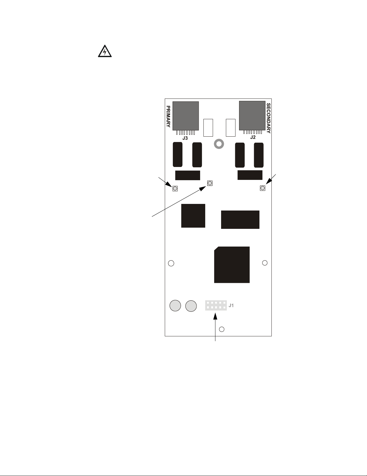
The DACT-UD module plugs into connector J2 on the MS-9600 main circuit board.
Primary Active LED
Kissoff LED
PH1
Primary
Phone Line
PH2
Secondary
Phone Line
Secondary Active LED
9600DACT.CDR
J1 Connector (located on back
of module) plugs into J2 on
MS-9600 main circuit board
Figure 2.2 DACT-UD Module
The following steps must be followed when installing the DACT module:
1. Remove all power (AC and DC) from the FACP before proceeding with the
installation
2. Remove the Keypad/Display from the main circuit board as described in the
beginning of this section
14 DACT-UD PN 51899:B1 1/25/05
Page 15
Installation in MS-9600 FACP DACT-UD Installation
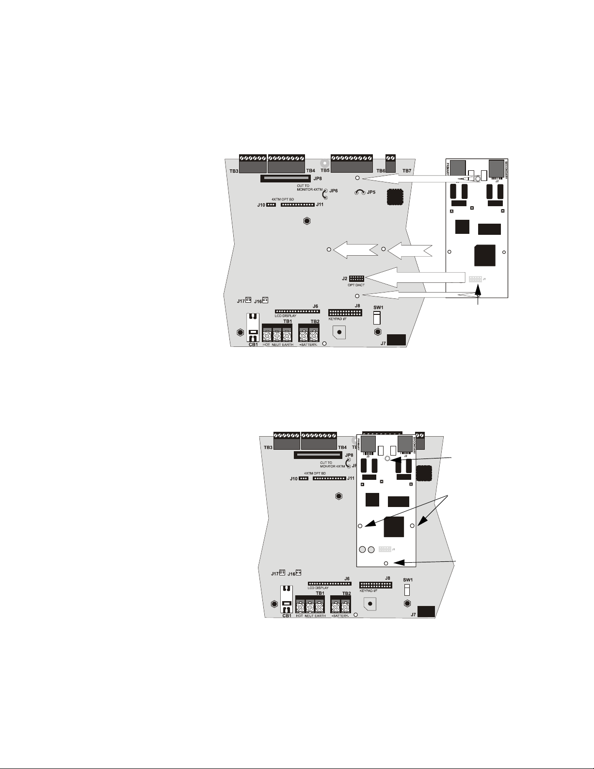
3. Insert the supplied plastic snap-in standoff into mounting hole located at the
bottom center of the DACT-UD module (insert into back of board)
4. Carefully plug connector J1 on the back of the DACT-UD module into connector
J2 on the MS-9600 main circuit board, being careful not to bend any pins and at
the same time, insert plastic snap-in standoff into mounting hole in main board
5. Align the mounting holes in the DACT module with the premounted standoffs on
the FACP main circuit board
Standoff
Standoff
Standoff
J2
Standoff (snap-in)
J1
J1 Connector located on
back of DACT module
Figure 2.3 DACT J1 Connector to FACP J2 Connector
6. Secure the module to the standoffs on the main circuit board with the three
screws supplied with the DACT-UD. It is important that the supplied screws be
used to secure the module to the metal standoff in order to help protect against
electrical transients.
Mounting Screw
Mounting Screws
96dact2.CDR
Snap-in Standoff
96dact3.CDR
Figure 2.4 DACT Installation on Standoffs
7. Reinstall the Keypad/Display on the main circuit board by positioning the unit
over the appropriate standoffs and securing with the screws which were loosened
in step 2
8. Make certain to program the control panel for DACT operation
DACT-UD PN 51899:B1 1/25/05 15
Page 16
DACT-UD Installation Installation in MS-9600 FACP
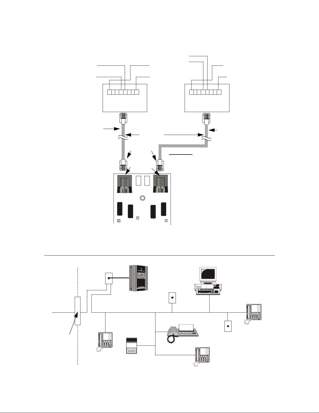
9. Refer to "Digital Communicator" on page 10, before proceeding with this step.
Connect the premises primary and secondary phone lines to the DACT as
illustrated in Figure 2.5 and test the system for correct operation
Primary Lines
Incoming Telco Phone Lines
Tip
Ring
Primary Phone Line PH-1
Green Wire
Red Wire
1 2 3 4 5 6 7 8
RJ3 1-X
Jack
PH1
Ring
Red Wire
Ring
Tip
To premise phones
Tip
Note: Shorting bars inside RJ31X Jack
removed during male plug insertion
7 foot cable
(MCBL-7)
order separately
Male Plug
Connectors
Female
Connectors
J3
J2
CAUTION: It is critical that the DACT-UD
be located as the first device on the incoming
telephone circuit to properly function
PH2
Green Wire
1 2 3 4 5 6 7 8
RJ31 -X
Jack
Secondary Lines
Incoming Telco Phone Lines
Ring
To premise phones
Tip
Secondary Phone Line PH-1
DACT-UD
Figure 2.5 Wiring Phone Jacks
It is critical that the DACT be located as the first device on the incoming telephone circuit to properly function.
Customer Premises Equipment and Wiring
M
S
2
9
0
0
U
Network
Service
Provider’s
Facilities
RJ31X
Jack
D
Computer
Unused
RJ-11 Jack
MS-9600 with DACT-UD
Telephone
Line
Telephone
Network
Demarcation
Fax Machine
Unused
RJ-11 Jack
Point
Telephone
Answering
System
Telephone
Figure 2.6 DACT Installation
16 DACT-UD PN 51899:B1 1/25/05
Page 17

Programming the MS-9600 Fire Alarm Control Panel Programming for DACT-UD
SECTION 3 Programming for DACT-UD
3.1 Programming the MS-9600 Fire Alarm Control Panel
Refer to the MS-9600 Manual programming section for general programming
information. To program the MS-9600 FACP for use with the DACT-UD:
1. Press the Enter or Mode key to display the Read Status/Programming screen
2. Press 2 to access Programming
3. Enter the Master level password
4. Press the down arrow key twice to view the screen with the Option Modules
choice
OPTION MODULES
1=ANNUNCIATORS/UDACT
2=ON BOARD DACT
3=PRINTER/PC
Option Module Screen
5. Press 3 for Option Modules to access the Option Modules screen as shown to the
left
6. Program the FACP for use with the DACT-UD using the following procedure
3.1.1 On-Board DACT
The DACT-UD (Digital Alarm Communicator/Transmitter) is an optional module
which installs directly on the FACP main circuit board for communication to a
central station. Pressing 2 while viewing the Option Module Screen will cause the
following screens to be displayed:
ON BOARD DACT
1=ENABLED YES
2=PRIMARY PHONE
3=SECONDARY PHONE
On Board DACT Screen #1
ON BOARD DACT
1=SERVICE TERMINAL
2=CENTRAL STATION
3=MANUAL DIAL MODE
On Board DACT Screen #2
3.1.1.1 DACT-UD Enable
To enable the on-board DACT module, press 1 while viewing On Board DACT
Screen #1 until the display reads Enabled Yes. The display will toggle between
Enabled Yes and Enabled No with each press of the key.
DACT-UD PN 51899:B1 1/25/05 17
Page 18
Programming for DACT-UD Programming the MS-9600 Fire Alarm Control Panel
3.1.1.2 Primary Phone
Press 2 while viewing On Board DACT Screen #1 to program the type of primary
phone line being connected to the DACT. The following screen will be displayed:
ON BOARD DACT
PRIMARY PHONE LINE
1=TYPE TOUCHTONE
Primary Phone Line Screen
To select the type, press 1 while viewing the Primary Phone Line screen. The
following screen will be displayed:
PHONE LINE
1=TOUCHTONE
2=ROTARY 67/33
3=ROTARY 62/38
ON BOARD DACT
1=ENABLED
2=PRIMARY PHONE
3=SECONDARY PHONE
On Board DACT Screen #1
Primary Phone Type Screen
Press 1 to select Touchtone dialing, 2 to select Rotary dialing with a make/break
ratio of 67/33 or 3 to select Rotary dialing with a make/break ratio of 62/38.
3.1.1.3 Secondary Phone
Press 3 while viewing On Board DACT Screen #1 to program the type of secondary
phone line being connected to the DACT. The following screen will be displayed:
ON BOARD DACT
SECONDARY PHONE LINE
1=TYPE TOUCHTONE
Secondary Phone Line Screen
To select the type, press 1 while viewing the Secondary Phone Line screen. The
following screen will be displayed:
PHONE LINE
1=TOUCHTONE
2=ROTARY 67/33
3=ROTARY 62/38
Secondary Phone Type Screen
Press 1 to select Touchtone dialing, 2 to select Rotary dialing with a make/break
ratio of 67/33 or 3 to select Rotary dialing with a make/break ratio of 62/38.
18 DACT-UD PN 51899:B1 1/25/05
Page 19

Programming the MS-9600 Fire Alarm Control Panel Programming for DACT-UD
3.1.1.4 Service Terminal
ON BOARD DACT
1=SERVICE TERMINAL
2=CENTRAL STATION
3=MANUAL DIAL MODE
On Board DACT Screen #2
The MS-9600 can be programmed remotely from a PC using a modem and
telephone line. Information can also be retrieved from the FACP using the same
method. The Upload/Download option allows an operator to set the necessary
parameters to allow the uploading and downloading of data between the FACP and
PC. The Service Terminal selection provides the means for entering these
parameters.
Pressing 1 while viewing On Board DACT Screen #2 will cause the following
screens to appear:
SERVICE TERMINAL
1=PANEL ID
2=TERMINAL 1
3=TERMINAL 2
Service Terminal Screen #1
SERVICE TERMINAL
1=RING COUNT 3
Service Terminal Screen #2
3.1.1.4.1 Panel ID
The Panel Identification Number is a 4-digit code (valid digits being 0 - 9 and A - F)
that is used to identify the installed FACP. It is important to program this code into
the FACP the first time that downloading is performed so that the called Service
Terminal can identify the control panel. The factory default is 0000.
To program the Panel ID, press 1 while viewing Service Terminal Screen #1. The
following screen will be displayed:
PANEL ID
4 CHARACTER 0-F
Panel ID Screen
A flashing cursor will appear in the lower left corner of the display. Enter a 4-digit
code using the digits 0 - 9 and/or the letters A - F by entering the first character.
Press the right arrow key to move the cursor to the second position and enter the
second character. Follow the same procedure to enter the remaining characters.
After entering the fourth character, press the right arrow key and then press the
Enter key to store the Panel ID number.
DACT-UD PN 51899:B1 1/25/05 19
Page 20

Programming for DACT-UD Programming the MS-9600 Fire Alarm Control Panel
3.1.1.4.2 Terminal 1 and Terminal 2
Service Terminal #1 is generally designated as the FACP primary phone line used
for receiving phone calls from the service terminal (PC) being used for remote
programming. Service Terminal 2 is referred to as the secondary phone line.
Pressing 2 for Terminal 1 or 3 for Terminal 2 while viewing Service Terminal
Screen #1 will display the following screen:
SERVICE TERMINAL #
1=PHONE NUMBER
Service Terminal # Screen
Phone Number (Service Terminal)
The Service Terminal Phone Number will be used by the control panel to contact
the service terminal. Pressing 1 while viewing the Service Terminal # Screen will
cause the following screen to be displayed:
PHONE NUMBER
20 NUMBERS MAXIMUM
Printer-PC Screen
A flashing cursor will appear in the lower left corner. Enter the phone number for
the service terminal by keying in the first digit, pressing the left arrow key and
entering the second digit. Continue this process until all desired numbers have been
entered (maximum of 20 characters). Press the Enter key to store the phone number
in memory and return the display to the Service Terminal # Screen.
Valid entries are 0 - 9 and A - F with the numeric digits as dialed numbers and
letters representing the following functions:
• A = * on a Touchtone phone keypad
• B = # on a Touchtone phone keypad
• C = look for secondary dial tone for up to two seconds (then dial anyway)
• D = three second pause
• E = five second pause
• F = end of phone number (F is automatically entered for unused entry positions)
20 DACT-UD PN 51899:B1 1/25/05
Page 21

Programming the MS-9600 Fire Alarm Control Panel Programming for DACT-UD
3.1.1.4.3 Ring Count
The ring count designates the number of rings allowed on the phone line prior to
answering an incoming call from a service terminal. The factory default is 3 which
means the control panel will not answer an incoming call until 3 rings are detected.
This entry may be programmed for 1 to 25 rings. A setting of 00 prevents the panel
from answering incoming calls.
To change the Ring Count, press 1 while viewing the Service Terminal Screen #2.
The following screen will be displayed:
RING COUNT
0-25 RANGE
Ring Count Screen
A flashing cursor will appear in the lower left corner of the display. Enter the twodigit ring count which can be a value between 00 and 25. After the second digit is
entered, the display will return to the Service Terminal screen.
ON BOARD DACT
1=SERVICE TERMINAL
2=CENTRAL STATION
3=MANUAL DIAL MODE
On Board DACT Screen #2
3.1.1.5 Central Station
Central Station programming configures the control panel DACT for contacting the
central station. Pressing 2 while viewing On Board DACT Screen #2 will cause the
following screens to be displayed:
CENTRAL STATION
1=REPORTING DISABLED
2=REPORT BACKUP
3=CALL LIMIT
Central Station Screen #1
CENTRAL STATION
1=PRIMARY
2=SECONDARY
3=REPORT STYLE
Central Station Screen #2
3.1.1.5.1 Reporting Enable
To enable the DACT for reporting FACP activity to the central station, press 1 while
viewing Central Station Screen #1 so the display reads Reporting Enabled. Each
press of the 1 key will toggle the display between Reporting Disabled and
Reporting Enabled.
DACT-UD PN 51899:B1 1/25/05 21
Page 22

Programming for DACT-UD Programming the MS-9600 Fire Alarm Control Panel
3.1.1.5.2 Backup Reporting
The DACT can be programmed to transmit reports to primary and/or secondary
central station phone numbers as a backup. Press 2 while viewing Central Station
Screen #1 to display the following screen:
BACKUP REPORTING
1=BACKUP ONLY
2=BOTH
3=FIRST AVAILABLE
Backup Reporting Screen
Press 1 to have all reports transmitted to the central station secondary phone number
as a backup only if the primary phone line fails, 2 to transmit all reports to both the
primary and secondary phone numbers all of the time or 3 to send reports to the first
available phone number.
3.1.1.5.3 Trouble Call Limit (Dialer Runaway Prevention)
The Call Limit option limits the number of DACT trouble calls to the Central
Station, to a programmed amount between 0 and 99, for each unique trouble within
a 24 hour period. Separate limit counters keep track of each unique type of trouble.
Note that the number of phone line (communication) faults called to the Central
Station are not limited by this feature. No subsequent restoral message is sent to the
Central Station(s) for a particular trouble whose call limit has been reached. Local
DACT annunciation will still track the particular trouble and restoral.
To set the Trouble Call Limit, press 3 while viewing Central Station Screen #1. The
following screen will be displayed.
TROUBLE CALL LIMIT
00-99 RANGE
*
Backup Reporting Screen
Enter a value between 00 and 99, then press Enter to set the Call Limit to this value.
22 DACT-UD PN 51899:B1 1/25/05
Page 23

Programming the MS-9600 Fire Alarm Control Panel Programming for DACT-UD
3.1.1.5.4 Central Station Primary and Secondary Phone Numbers
CENTRAL STATION
1=PRIMARY
2=SECONDARY
3=REPORT STYLE
Central Station Screen #2
Pressing 1 for Primary or 2 for Secondary will cause the following screens to be
displayed.
CENTRAL STATION
1=TEST TIME INT 24
2=ACCOUNT CODE 0000
3=24HR TST TIME 0021
Primary/Secondary Screen #1
CENTRAL STATION
1=PHONE NUMBER
Primary/Secondary Screen #2
CENTRAL STATION
1=COMM FORMAT
ADEMCO-CONTACT-ID
Primary/Secondary Screen #3
CENTRAL STATION
1=EVENT CODES
Primary/Secondary Screen #4
DACT-UD PN 51899:B1 1/25/05 23
Page 24

Programming for DACT-UD Programming the MS-9600 Fire Alarm Control Panel
Test Time Interval
CENTRAL STATION
1=TEST TIME INT
2=ACCOUNT CODE
3=24HR TST TIME
Primary/Secondary Screen #1
Pressing 1 while viewing Primary/Secondary Screen #1 will cause the following
screens to be displayed:
TEST TIME INTERVAL
1=24 HOURS
2=12 HOURS
3=8 HOURS
Test Time Interval Screen #1
TEST TIME INTERVAL
1=6 HOURS
Test Time Interval Screen #2
The test report sent to the Central Station phone number may be sent once every 6,
8, 12 or 24 hours. Select the desired Test Time Interval by pressing the
corresponding digit in the screens shown above.
Account Code
Pressing 2 while viewing Primary/Secondary Screen #1 will cause the following
screen to be displayed:
ACCOUNT CODE
4 CHAR RANGE 0-F
Account Codes Screen
The Account Code, which is assigned by a Central Station, depends on the
communication format being used. The Account Code screen will have a flashing
cursor in the lower left corner. Enter the supplied account code using 0 - 9 and A- F
keys.
Note: If the Account Code being entered is a three digit number, enter the three
digits first and then add a 0 (zero) as the fourth digit.
24 DACT-UD PN 51899:B1 1/25/05
Page 25

Programming the MS-9600 Fire Alarm Control Panel Programming for DACT-UD
24 Hour Test Time
CENTRAL STATION
1=TEST TIME INT
2=ACCOUNT CODE
3=24HR TST TIME
Primary/Secondary Screen #1
Pressing 3 while viewing Primary/Secondary Screen #1 will cause the following
screen to be displayed:
24 HOUR TEST TIME
RANGE 0000-2359
24 Hour Test Time Screen
Use the 24 Hour Test Time screen to program the time that the DACT-UD will
transmit the 24 Hour Test to the Central Station. A flashing cursor will appear in the
lower left corner of the screen. Enter a four digit number representing the test time
using military time (0000 = midnight and 2359 = 11:59PM).
CENTRAL STATION
1=PHONE NUMBER
Primary/Secondary Screen #2
Phone Number
Pressing 1 while viewing Primary/Secondary Screen #2 will cause the following
screen to be displayed:
PHONE NUMBER
20 NUMBERS MAXIMUM
Phone Number Screen
The Phone Number screen is used to enter the Central Station phone number that
the DACT-UD will be contacting. A maximum of 20 characters can be entered with
valid entries being 0 - 9 and A - F where A = *, B = #, C = look for secondary dial
tone for up to 2 seconds (then dial anyway), D = 3 second pause, E = 5 second pause
and F = end of phone number (must be entered at end of phone number).
A flashing cursor will appear in the lower left corner of the screen. Enter the first
digit then press the right arrow key to move the cursor to the right one position.
Enter the second digit and repeat the process until all digits are entered. Press the
Enter key to store the phone number in memory.
Enter the digits as you would like the number to be dialed. For example, if it’s
necessary to dial 9 before dialing a number outside the building, you may wish to
pause after dialing 9. Enter 9 followed by D for a three second pause or E for a five
second pause then the phone number followed by an F to indicate the end of the
number.
DACT-UD PN 51899:B1 1/25/05 25
Page 26

Programming for DACT-UD Programming the MS-9600 Fire Alarm Control Panel
Pressing 1 while viewing Primary/Secondary Screen #3 will cause the following
CENTRAL STATION
1=COMM FORMAT
screens to be displayed:
COMM FORMAT
Primary/Secondary Screen #3
1=ADEMCO EXPRESS 4P1
2=ADEMCO EXPRESS 4P2
3=3P1S C18 A23
Comm Format Screen #1
COMM FORMAT
1=3P1E C18 A23
2=3P1S C19 A14
3=3P1E C19 A14
Comm Format Screen #2
COMM FORMAT
1=4P1S C18 A23
2=4P1E C18 A23
3=4P1S C19 A14
Comm Format Screen #3
COMM FORMAT
1=4P1E C19 A14
2=4P2S C18 A23
3=4P2E C18 A23
Comm Format Screen #4
COMM FORMAT
1=4P2S C19 A14
2=4P2E C19 A14
3=ADEMCO CONTACT ID
Comm Format Screen #5
26 DACT-UD PN 51899:B1 1/25/05
Page 27

Programming the MS-9600 Fire Alarm Control Panel Programming for DACT-UD
The Communication Format is determined by the type of receiver that the
DACT-UD is transmitting to. Consult your Central Station for proper selection or
consult our factory representatives. For any format chosen, the control panel
automatically programs all of the event codes.
Select the Communication Format by pressing the corresponding number key while
viewing the appropriate Comm Format screen. The following table describes each
format:
Table 3.1 Communication Formats
Screen Selection Communication Format Description
ADEMCO EXPRESS 4P1 4+1 Ademco Express Standard, DTMF, 1400/2300 ACK
ADEMCO EXPRESS 4P2 4+2 Ademco Express Standard, DTMF, 1400/2300 ACK
3P1S C18 A23 3+1 Standard 1800 Hz Carrier, 2300 Hz ACK
3P1E C18 A23 3+1 Expanded 1800 Hz Carrier, 2300 Hz ACK
3P1S C19 A14 3+1 Standard 1900 Hz Carrier, 1400 Hz ACK
3P1E C19 A14 3+1 Expanded 1900 Hz Carrier, 1400 Hz ACK
4P1S C18 A23 4+1 Standard 1800 Hz Carrier, 2300 Hz ACK
4P1E C18 A23 4+1 Expanded 1800 Hz Carrier, 2300 Hz ACK
4P1S C19 A14 4+1 Standard 1900 Hz Carrier, 1400 Hz ACK
4P1E C19 A14 4+1 Expanded 1900 Hz Carrier, 1400 Hz ACK
4P2S C18 A23 4+2 Standard 1800 Hz Carrier, 2300 Hz ACK
4P2E C18 A23 4+2 Expanded 1800 Hz Carrier, 2300 Hz ACK
4P2S C19 A14 4+2 Standard 1900 Hz Carrier, 1400 Hz ACK
4P2E C19 A14 4+2 Expanded 1900 Hz Carrier, 1400 Hz ACK
ADEMCO CONTACT ID Contact ID, DTMF, 1400/2300 ACK
CENTRAL STATION
1=EVENT CODES
Primary/Secondary Screen #4
Event Codes
Pressing 1 while viewing Primary/Secondary Screen #4 will cause the following
screen to be displayed:
EVENT CODES
1=PULL STATION
2=MON-USER-DEF-1
3=WATERFLOW
Event Code Screen
Pressing the down arrow key allows viewing of all Events associated with the
selected Communication Format. Pressing the number corresponding to the event
displayed in each screen will display its default event code which can be customized
by the programmer. For example, pressing 1 for Pull Station will display a screen
similar to the following which allows the Event Code to be changed from the
default value.
PULL STATION
ALARM 000
Event Code Screen
The tables on the following pages list all of the Events and their default Event
Codes for the various Communication Formats.
DACT-UD PN 51899:B1 1/25/05 27
Page 28

Programming for DACT-UD Programming the MS-9600 Fire Alarm Control Panel
3+1, 4+1 Express and 4+1 Standard
The information shown in Table 3.2 is automatically programmed for the Central
Station phone number Event Codes when any of these Formats are selected. Enter 0
for an Event Code Setting to disable the report.
Table 3.2 Event Codes
Event Description Event Code Settings
Active Restoral
PULL STATION 1 E
MON-USER-DEF-1 1 E
WATERFLOW 1 E
MON-USER-DEF-2 1 E
SMOKE (PHOTO) 1 E
DET-USER-DEF-1 1 E
SMOKE (ION) 1 E
DET-USER-DEF-2 1 E
HEAT DETECT 1 E
DET-USER-DEF-3 1 E
SMOKE DUCT-P 1 E
DET-USER-DEF-4 1 E
DUCT SUPERVISORY 8 E
DET-USER-DEF-5 8 E
not used 0 0
not used 0 0
not used 0 0
not used 0 0
MONITOR 1 E
MON-USER-DEF-3 1 E
not used 0 0
not used 0 0
SMOKE CONVEN 1 E
MON-USER-DEF-5 1 E
HEAT DETECT 1 E
MON-USER-DEF-6 1 E
MEDIC ALERT 0 0
MON-USER-DEF-7 0 0
HAZARD ALERT 0 0
MON-USER-DEF-8 0 0
TORNADO ALRT 0 0
MON-USER-DEF-9 0 0
PHONE 0 0
MON-USER-DEF-10 0 0
TAMP ER 8 E
MON-USER-DEF-11 8 E
MON SUPERVISORY 8 E
MON-USER-DEF-12 8 E
MON SUPERV AUTO 8 E
MON-USER-DEF-13 8 E
POWER MON 6 A
MON-USER-DEF-14 6 A
TROUBLE MON refer to POINT_FAULT for codes
MON-USER-DEF-15 refer to POINT_FAULT for codes
PROCESS MON 0 0
MON-USER-DEF-16 0 0
28 DACT-UD PN 51899:B1 1/25/05
Page 29

Programming the MS-9600 Fire Alarm Control Panel Programming for DACT-UD
Table 3.2 Event Codes (Continued)
PROCMON AR 0 0
MON-USER-DEF-17 0 0
not used 0 0
not used 0 0
POINT_FAULT F D
POINT_DISABLE 4 5
AC_FAIL 9 3
DRILL B C
SLC 1 OPEN FAULT 6 A
SLC 1 SHORT FAULT 6 A
SLC 2 OPEN FAULT 6 A
SLC 2 SHORT FAULT 6 A
GROUND FAULT 6 A
LOW BATTERY 6 A
NO_BATTERY 6 A
TELCO LINE 1 6 A
TELCO LINE 2 6 A
COMM FAULT 1 6 A
COMM FAULT 2 6 A
TOTAL COMM FLT 0 0
PRINTER FAULT 6 A
NAC 1 FAULT 6 A
NAC 2 FAULT 6 A
NAC 3 FAULT 6 A
NAC 4 FAULT 6 A
not used 0 0
VOICE EVACUATION 6 A
ACS FAULT 6 A
LCD_80F FAULT 6 A
NAC 1 DISABLE 4 5
NAC 2 DISABLE 4 5
NAC 3 DISABLE 4 5
NAC 4 DISABLE 4 5
MEMORY FAULT 6 A
CHARGER FAULT 6 A
OPTION CARD 1 FAULT 6 A
OPTION CARD 2 FAULT 6 A
SLC 2 FAULT 6 A
ZONE DISABLE 4 5
NAC_KEY_FLT 6 A
NO_DEVICES_INSTLLD 6 A
OFF_NORMAL_MESSAGE 6 A
24_HOUR_TEST 9 0
24 HOUR ABNORMAL TES F 0
UPDOWN REQUEST 7 0
UPLOAD SUCCESS 7 0
DOWNLOAD SUCCESS 7 0
UPDOWN FAILURE 7 0
GENERAL_ALARM 0 0
GENERAL_SUPERVISORY 0 0
DACT-UD PN 51899:B1 1/25/05 29
Page 30

Programming for DACT-UD Programming the MS-9600 Fire Alarm Control Panel
4+2 Standard, 4+2 Express, 3 + 1, 4+1 and 4+2 Expanded Formats
The information shown in Table 3.3 is automatically programmed for the Central
Station phone number Event Codes when any of these Formats are selected. Enter
00 for an Event Code Setting to disable the report.
Table 3.3 Event Codes
Event Description Event Code Settings
Active Restoral
PULL STATION 11 E1
MON-USER-DEF-1 11 E1
WATERFLOW 11 E1
MON-USER-DEF-2 11 E1
SMOKE (PHOTO) 11 E1
DET-USER-DEF-1 11 E1
SMOKE (ION) 11 E1
DET-USER-DEF-2 11 E1
HEAT DETECT 11 E1
DET-USER-DEF-3 11 E1
SMOKE DUCT-P 11 E1
DET-USER-DEF-4 11 E1
DUCT SUPERVISORY 81 E1
DET-USER-DEF-5 81 E1
not used 00 00
not used 00 00
not used 00 00
not used 00 00
MONITOR 11 E1
MON-USER-DEF-3 11 E1
not used 00 00
not used 00 00
SMOKE CONVEN 11 E1
MON-USER-DEF-5 11 E1
HEAT DETECT 11 E1
MON-USER-DEF-6 11 E1
MEDIC ALERT 00 00
MON-USER-DEF-7 00 00
HAZARD ALERT 00 00
MON-USER-DEF-8 00 00
TORNADO ALRT 00 00
MON-USER-DEF-9 00 00
PHONE 00 00
MON-USER-DEF-10 00 00
TAMPER 81 E1
MON-USER-DEF-11 81 E1
MON SUPERVISORY 81 E1
MON-USER-DEF-12 81 E1
MON SUPERV AUTO 81 E1
MON-USER-DEF-13 81 E1
POWER MON 81 E1
MON-USER-DEF-14 81 E1
TROUBLE MON refer to POINT_FAULT for codes
MON-USER-DEF-15 refer to POINT_FAULT for codes
PROCESS MON 00 00
MON-USER-DEF-16 00 00
30 DACT-UD PN 51899:B1 1/25/05
Page 31

Programming the MS-9600 Fire Alarm Control Panel Programming for DACT-UD
Table 3.3 Event Codes (Continued)
PROCMON AR 00 00
MON-USER-DEF-17 00 00
not used 00 00
not used 00 00
POINT_FAULT F1 D1
POINT_DISABLE 41 51
AC_FAIL 92 93
DRILL 97 98
SLC 1 OPEN FAULT 43 53
SLC 1 SHORT FAULT 44 54
SLC 2 OPEN FAULT 4B 5B
SLC 2 SHORT FAULT 4C 5C
GROUND FAULT 61 A1
LOW BATTERY 62 A2
NO_BATTERY 63 A3
TELCO LINE 1 64 A4
TELCO LINE 2 65 A5
COMM FAULT 1 6A AA
COMM FAULT 2 6B AB
TOTAL COMM FLT 00 00
PRINTER FAULT 6C AC
NAC 1 FAULT 66 A6
NAC 2 FAULT 67 A7
NAC 3 FAULT 68 A8
NAC 4 FAULT 69 A9
not used 00 00
VOICE EVACUATION 00 00
ACS FAULT 6D AD
LCD_80F FAULT 6E AE
NAC 1 DISABLE 4B 5B
NAC 2 DISABLE 4C 5C
NAC 3 DISABLE 4D 5D
NAC 4 DISABLE 4E 5E
MEMORY FAULT 46 56
CHARGER FAULT 47 57
OPTION CARD 1 FAULT 48 58
OPTION CARD 2 FAULT 49 59
SLC 2 FAULT 4F 5F
ZONE DISABLE 42 52
NAC_KEY_FLT 4B 5B
NO_DEVICES_INSTLLD 4A 5A
OFF_NORMAL_MESSAGE 6F AF
24_HOUR_TEST 99 00
24 HOUR ABNORMAL TES FB 00
UPDOWN REQUEST 71 00
UPLOAD SUCCESS 72 00
DOWNLOAD SUCCESS 73 00
UPDOWN FAILURE 74 00
GENERAL_ALARM 00 00
GENERAL_SUPERVISORY 00 00
DACT-UD PN 51899:B1 1/25/05 31
Page 32

Programming for DACT-UD Programming the MS-9600 Fire Alarm Control Panel
Ademco Contact ID Format
The information shown in Table 3.4 is automatically programmed for the Central
Station phone number Event Codes when Ademco Contact ID Format is selected.
Enter 000 for an Event Code Setting to disable the report.
Table 3.4 Event Codes
Event Description Event Code Settings
Active
PULL STATION 115
MON-USER-DEF-1 115
WATERFLOW 113
MON-USER-DEF-2 113
SMOKE (PHOTO) 111
DET-USER-DEF-1 111
SMOKE (ION) 111
DET-USER-DEF-2 111
HEAT DETECT 114
DET-USER-DEF-3 114
SMOKE DUCT-P 116
DET-USER-DEF-4 116
DUCT SUPERVISORY 200
DET-USER-DEF-5 200
not used 000
not used 000
not used 000
not used 000
MONITOR 110
MON-USER-DEF-3 110
not used 000
not used 000
SMOKE CONVEN 111
MON-USER-DEF-5 111
HEAT DETECT 114
MON-USER-DEF-6 114
MEDIC ALERT 100
MON-USER-DEF-7 100
HAZARD ALERT 150
MON-USER-DEF-8 150
TORNADO ALRT 150
MON-USER-DEF-9 150
PHONE 000
MON-USER-DEF-10 000
TAMPER 144
MON-USER-DEF-11 144
MON SUPERVISORY 200
MON-USER-DEF-12 200
MON SUPERV AUTO 200
MON-USER-DEF-13 200
POWER MON 330
MON-USER-DEF-14 330
TROUBLE MON refer to POINT_FAULT for code
MON-USER-DEF-15 refer to POINT_FAULT for code
PROCESS MON 000
MON-USER-DEF-16 000
32 DACT-UD PN 51899:B1 1/25/05
Page 33

Programming the MS-9600 Fire Alarm Control Panel Programming for DACT-UD
Table 3.4 Event Codes (Continued)
PROCMON AR 000
MON-USER-DEF-17 000
not used 000
not used 000
POINT_FAULT 380
POINT_DISABLE 570
AC_FAIL 301
DRILL 604
SLC 1 OPEN FAULT 371
SLC 1 SHORT FAULT 372
SLC 2 OPEN FAULT 371
SLC 2 SHORT FAULT 372
GROUND FAULT 310
LOW BATTERY 302
NO_BATTERY 311
TELCO LINE 1 351
TELCO LINE 2 352
COMM FAULT 1 354
COMM FAULT 2 355
TOTAL COMM FLT 000
PRINTER FAULT 336
NAC 1 FAULT 321
NAC 2 FAULT 322
NAC 3 FAULT 326
NAC 4 FAULT 327
not used 000
VOICE EVACUATION 337
ACS FAULT 333
LCD_80F FAULT 334
NAC 1 DISABLE 521
NAC 2 DISABLE 522
NAC 3 DISABLE 526
NAC 4 DISABLE 527
MEMORY FAULT 304
CHARGER FAULT 300
OPTION CARD 1 FAULT 331
OPTION CARD 2 FAULT 332
SLC 2 FAULT 370
ZONE DISABLE 570
NAC_KEY_FLT 300
NO_DEVICES_INSTLLD 380
OFF_NORMAL_MESSAGE 308
24_HOUR_TEST 602
24 HOUR ABNORMAL TES 608
UPDOWN REQUEST 411
UPLOAD SUCCESS 416
DOWNLOAD SUCCESS 412
UPDOWN FAILURE 413
GENERAL_ALARM 000
GENERAL_SUPERVISORY 000
DACT-UD PN 51899:B1 1/25/05 33
Page 34

Programming for DACT-UD Programming the MS-9600 Fire Alarm Control Panel
Report Style
CENTRAL STATION
1=PRIMARY
2=SECONDARY
3=REPORT STYLE
Central Station Screen #2
Pressing 3 while viewing Central Station Screen #2 will cause the Report Style
display to toggle between Point and Zone. Setting the Report Style to Point will
program the DACT to report individual point status to the Central Station. The
control panel is capable of monitoring a total of 636 addressable devices. Setting
the Report Style to Zone will program the DACT to report zone status to the Central
Station. The control panel is capable of monitoring a total of 99 individual zones.
CENTRAL STATION
1=PRIMARY
2=SECONDARY
3=REPORT STYLE POINT
Central Station Screen #2
Notes on Central Station Reporting:
1. SLC Loop 1, Detector Address 01 will be reported to the Central Station as
Point 01, Detector Address 02 as Point 02, with reports continuing in a similar
fashion all the way up to Detector Address 159 which will be reported as Point
159.
2. SLC Loop 1, Module Address 01 will be reported to the Central Station as
Point 160, Module Address 02 will be reported to the Central Station as Point
161, with reports continuing in a similar fashion all the way up to Module
Address 159 which will be reported as Point 318.
3. SLC Loop 2, Detector Address 01 will be reported to the Central Station as
Point 319, Detector Address 02 as Point 320, with reports continuing in a
similar fashion all the way up to Detector Address 159 which will be reported
as Point 477.
4. SLC Loop 2, Module Address 01 will be reported to the Central Station as
Point 478, Module Address 02 as Point 479, with reports continuing in a
similar fashion all the way up to Module Address 159 which will be reported as
Point 636.
34 DACT-UD PN 51899:B1 1/25/05
Page 35

Programming the MS-9600 Fire Alarm Control Panel Programming for DACT-UD
3.1.1.6 Manual Dial Mode
ON BOARD DACT
1=SERVICE TERMINAL
2=CENTRAL STATION
3=MANUAL DIAL MODE
On Board DACT Screen #2
Pressing 3 while viewing On Board DACT Screen #2 will cause the following
screen to be displayed:
MANUAL DIAL MODE
1=PRIMARY PHONE
2=SECONDARY PHONE
Pressing 1 for Primary Phone or 2 for Secondary Phone will display the following:
MANUAL DIAL MODE
1=GO OFF HOOK
2=DIAL DIGIT(S)
3=GO ON HOOK
Pressing 1 for Go Off Hook will cause the DACT to access the selected phone line
(similar to taking the phone handset off the cradle). The selected phone line’s red
Active LED will turn on.
Pressing 2 for Dial Digit(s) will display a screen which allows the user to key in the
phone number to be dialed. The first digit is keyed in and then the right arrow key
is pressed to move the cursor to the next position. The next digit is keyed in and the
process is repeated until all digits have been entered. Pressing the Enter key will
cause the number just entered to be dialed.
Pressing 3 for Go On Hook will cause the DACT to hang-up, deselecting the
previously selected phone line. The phone line’s red Active LED will turn off.
DACT-UD PN 51899:B1 1/25/05 35
Page 36

Programming for DACT-UD Remote Site Upload/Download
3.2 Remote Site Upload/Download
The control panel may be programmed or interrogated off-site via the public switched
telephone network. Any personal computer with Windows 95, a 1200 baud Hayes
compatible modem and Fire•Lite Upload/Download software P/N PK-CD may serve as
a Service Terminal. The Upload/Download software allows the following:
Download of the entire program
Download of an individual program item
Upload of the entire program
Upload of an individual program item
Upload of the entire program plus history file, walktest data, current status,
system voltages and time & date
Real-time upload, either continuous or ‘snapshot’ (one time) of current status
or system voltages
Execution of control panel functions such as Trouble Silence, Manual
Evacuate, Manual Evacuate Restore, Zone/NAC Disable, Zone/NAC Enable
and Set Time & Date
WA R NI N G : Changes to program entries occur as a result of the downloading process.
After successful downloading, make certain to perform the following steps:
1. Print out all programmed data via print mode or manually view programmed
entries and compare to intended program data
2. Test all affected panel operations
3. Immediately correct any problems found
3.2.1 Downloading Program: General
Any time that the control panel is downloaded, whether initiated at the jobsite or
remotely, a secret code (Factory Default 0000) is verified between the control panel and
the Service Terminal. Changing the Secret Code may only be accomplished at the
Service Terminal and subsequently loaded into the control panel. Future upload or
download requests cause verification of the secret code by the control panel before
processing of data is allowed. If the secret code is not verified, the control panel will
terminate the request immediately.
While the control panel is communicating with the Service Terminal, the DACT-UD’s
green Modem LED and one of the red Line Seize LEDs will remain on steady. At the
conclusion of a successful download transaction, the green Kissoff LED will come on
steady for one second. Upon termination of communication, the green Modem LED
will turn off and the red Line Seize LED will turn off.
In order to download the panel (whether initiated at the jobsite or remotely) the
following must be true:
The control panel may be in any mode of operation, including Disable, Enable
and Drill. Downloading is not possible if the communicator is active during
Central Station communications or while testing the phone lines while in
Troubleshoot mode
There cannot be any active communications ongoing with a Central Station
receiver
All active events must be successfully ‘Kissed-off’ by the Central Station(s)
The communicator must be in a standby state with no new information waiting
to be transmitted to a Central Station
36 DACT-UD PN 51899:B1 1/25/05
Page 37

Remote Site Upload/Download Programming for DACT-UD
Two basic communication mechanisms are supported as follows:
• Download with Callback - the Service Terminal calls the control panel. The
control panel answers the call, confirms the calling party then hangs-up. The
Service Terminal then waits for a callback from the control panel. After the
control panel calls the Central Station and successfully reports that a request for
downloading has been received, the control panel calls the Service Terminal
back. Upon secret code verification, data transfers occur. When the data
transfers are completed and the Service Terminal disconnects from the control
panel, the panel calls the Central Station back to confirm either successful or
unsuccessful results
• Download with Callback Disabled - the Service Terminal calls the control panel.
No hang-up sequence occurs. Data transfers proceed.
Note: Callback enable/disable is controlled by the master user at the Service Terminal
on a per call basis.
Anytime a download with callback is initiated, the control panel will first contact the
primary Central Station or both the primary and secondary Central Stations or the first
available Central Station phone number (depending on which option has been
programmed into the control panel) to report a request for upload/download message.
Once the request is ‘Kissed-off’ by the Central Station(s), the control panel will then
call the appropriate Service Terminal and begin the downloading process.
Anytime a download without callback is initiated, the control panel and the Service
Terminal will communicate and transfer data without first contacting a Central Station.
When the data transfers are completed and the control panel disconnects from the
Service Terminal, the panel will call the Central Station and report the following:
• Upload/download request received
• Upload and/or download successful or
• Upload/download failed
To prevent the request for up/download message(s) from being reported to the Central
Stations(s), disable all upload/download reports back to both Central Stations.
During the downloading process, the fire protection remains active
trouble or alarm condition occur, the control panel immediately terminates
downloading and processes the trouble or alarm locally and transmits the information
to the Central Station(s).
. Should a system
3.2.2 Security Features
Remote site upload and download with the control panel has been carefully designed to
include key security features to ensure proper functionality. The key features are listed
and explained below.
Secret Code Verification
A secret code is stored in the control panel by a Service Terminal to prevent
unauthorized access. The secret code is created at the Service Terminal in Password
level 1 and cannot be viewed or changed by anyone other than a user with access to
level 1. Viewing of the secret code is prohibited at the control panel. Prior to allowing
an upload or download of data, the control panel will verify the secret code transmitted
by the Service Terminal.
Time-out at Control Panel
Upon answering an incoming call on either the primary or secondary Central Station
phone line, the panel will listen for a modem connection signal. If this signal is not
received within 30 seconds, the panel will disconnect the call.
Upon successful connection (secret code verified and callback complete, if applicable),
if no communication occurs within five minutes, the panel will disconnect the call.
DACT-UD PN 51899:B1 1/25/05 37
Page 38

Programming for DACT-UD Remote Site Upload/Download
Callback to Service Terminal
Anytime that the panel is remotely requested to allow an upload or download with
callback, it will confirm the source of the incoming call, hang-up and call back the
calling party (Service Terminal phone number).
Panel Identification Number
The panel identification number will be used to automatically identify the panel to the
Service Terminal (when the panel calls the Service Terminal).
Calls initiated at the panel must be coordinated a the Service Terminal manually. Note
that the Service Terminal will not pickup the incoming call unless operating on the
communications screen. The Service Terminal will not recognize a control panel
initiated call unless the secret code is at the factory default settings.
Error Checking
As each block of data is received by the control panel, it is checked for accuracy. If an
error is detected, the block is retransmitted until correct, up to a maximum of four
times. If the Secret Code is not verified and four errors occur, the call is disconnected
and the report that the upload/download was not successful is called to the Central
Station(s).
Central Station Acknowledge
There is an option whereby the control panel will report to one or both Central Stations
that a request for uploading or downloading has been received prior to processing the
call. This is called the callback option. If the Central Station(s) does not acknowledge
receipt of this request, uploading or downloading is prohibited. If acknowledged by the
Central Station(s), another message is transmitted informing the Central Station(s) that:
(1) downloading was successful, (2) uploading was successful or (3) uploading/
downloading was not successful.
Data Protection/Integrity
Options allow programming of single data entries or the entire program. Use caution
when selecting programming choices and verify all entries via an upload or manual
check at the control panel. Data blocks containing user programming options are
protected from partial programming due to faulty phone connections, line noise and
other errors.
38 DACT-UD PN 51899:B1 1/25/05
Page 39

Downloading Initiated at a Service Terminal Programming for DACT-UD
3.3 Downloading Initiated at a Service Terminal
Before initiating the Download procedure, make certain that the control panel is in the
standby state with the red Line Seize LED, green Modem and Kissoff LEDs off.
Once an incoming call is accepted/answered by the control panel, the panel will:
1. Establish basic modem connection
2. Verify secret code
3. Verify callback vs. no callback request from the Service Terminal. If callback is
requested then perform steps 4 through 10. If no callback is requested then
perform steps 9 and 10 only
4. Identify the Service Terminal location
5. Hang-up/disconnect call
6. Call the Central Station(s) and transmit a request for upload/download message
(if programmed to do so). If this message is accepted, the control panel will
proceed to the next step
7. Return call to Service Terminal
8. Verify secret code
9. Begin downloading
10. Upon completion of download, call Central Station(s) back and report a
successful download or failed upload/download status (if programmed to do so)
3.4 Uploading Initiated at a Service Terminal
Items that may be uploaded from the control panel to a Service Terminal are:
• All or portions of programmed data plus the real time clock, time and date
• Entire Walktest data file in real-time continuous or as a ‘snapshot’
• Troubleshoot system voltages in real-time continuous or as a ‘snapshot’
• Entire event History file
• Current system status in real-time continuous or a a ‘snapshot’
Uploading is possible at any time provided the following conditions are true:
The control panel may be in any mode of operation. Uploading is not possible
if the communicator is active or while testing the phone lines while in
troubleshoot mode
There cannot be any active communications ongoing with a Central Station
receiver
All active events must be successfully ‘Kissed-off’ by the Central Station(s).
The communicator must be in a standby state with no new information waiting
to be transmitted to a Central Station
DACT-UD PN 51899:B1 1/25/05 39
Page 40

Programming for DACT-UD Simultaneous Data Transfers
Once an incoming call is accepted/answered by the control panel, the panel will
1. Establish basic modem connection
2. Verify secret code
3. Verify callback vs. no callback request from the Service Terminal. If callback is
requested then perform steps 4 through 10. If no callback is requested then
perform steps 9 and 10 only
4. Identify the Service Terminal location
5. Hang-up/disconnect call
6. Call the Central Station(s) and transmit a request for upload/download message
(if programmed to do so). If this message is accepted, the control panel will
proceed to the next step
7. Return call to Service Terminal
8. Verify secret code
9. Begin uploading
10. Upon completion of upload, call Central Station(s) back and report a successful
upload or failed upload/download status (if programmed to do so)
During the uploading process, the fire protection remains active. Should a system
trouble or alarm condition occur, the control panel immediately terminates uploading
and processes the trouble or alarm locally and transmits the information to the Central
Station(s).
3.5 Simultaneous Data Transfers
Uploading and downloading may take place on a single telephone call. Control and
selection of the data transaction is coordinated at the Service Terminal. This eliminates
multiple phone calls, allows instant verification of downloaded data files and simplifies
the overall process.
40 DACT-UD PN 51899:B1 1/25/05
Page 41

Simultaneous Data Transfers Central Station Communications
SECTION 4 Central Station Communications
The DACT-UD transmits zone and system status reports to Central Stations via the public switched telephone network. Two supervised telephone line connections are made
to interface the DACT to the telephone lines. Two optional 7 foot telephone cords are
available for this purpose and can be purchased separately.
The control panel supervises both telephone lines for proper voltage. A delay of two
minutes will occur before a fault in either phone line connection is reported as a trouble.
When a fault is detected, an audible trouble signal will sound, the yellow trouble LED
will blink, the display will show a DACT communication trouble and the trouble
condition will be reported to the Central Station over the remaining operational phone
line.
The DACT-UD comes with line seizure capability provided for both the primary and
secondary telephone line interfaces. Any time that the control panel needs to make a
call to a Central Station, line seizure will disconnect any local premises phones sharing
the same telephone line.
All transmissions to the Central Stations will be sent over the primary phone line. In
the event of noisy phone lines, transmissions will be sent over the backup secondary
phone line.
Two phone numbers must be programmed, the primary Central Station phone number
and the secondary Central Station phone number. All system reports will be transmitted
to the primary Central Station phone number. Reports will automatically be sent to the
secondary Central Station phone number if attempts to transmits to the primary Central
Station phone number are unsuccessful. Note that as an option, all reports may also be
sent to the secondary Central Station phone number.
The DACT-UD installed on the MS-9600 meets NFPA 72 National Fire Code reporting
requirements for: (a) the type of signal, (b) condition and (c) location of the reporting
premises. The general priority reporting structure is:
1. Zone Alarms and Restores
2. Zone Troubles and Restores
3. System Troubles and Restores
4. 24-hour Test
DACT-UD PN 51899:B1 1/25/05 41
Page 42

Central Station Communications Simultaneous Data Transfers
The control panel is capable of reporting detailed messages depending upon the format
in use. Table 4-1 shows the reporting structure for all formats.
TABLE 4-1:Format Selection
Format Format Format Format
Report
Alarm SSS(S) A
Alarm Restore SSS(S) RA
Zone Trouble
(Zone Open)
Zone Trouble Restore SSS(S) RTZ
System Trouble SSS(S) TS
System Trouble Restore SSS(S) RTS
Zone Disable SSS(S) DZ
Zone Disable Restore SSS(S) RDZ
Low Battery SSS(S) L
Low Battery Restore SSS(S) RL
AC Loss SSS(S) P
AC Loss Restore SSS(S) RP
Fire Drill SSS(S) FD
Fire Drill Restore SSS(S) RFD
Supervisory Condition SSS(S) V
Supervisory Condition
Restore
Test Report SSS(S) X SSS(S) X SSSS XX2 SSSS XX2
Upload or Download SSS(S) UD SSS(S) UD SSS UDUD2 SSS UDUD2
3+1/4+1/Standard
4+1 Express
SSS(S) TZ
SSS(S) RV
3+1/4+1/Expanded
SSS(S) A
AAA(A) Z
SSS(S) RA
RARARA(RA) Z
SSS(S) TZ
TZTZTZ(TZ) Z
SSS(S) RTZ
RTZ RTZRTZ( RTZ ) Z
SSS(S) TS
TSTSTS(TS) Y
SSS(S) RTS
RTS RTSRTS( RTS) Y
SSS(S) DZ
DZDZDZ(DZ) Z
SSS(S) RDZ
RDZRDZRDZ(RDZ) Z
SSS(S) L
LLL(L) L2
SSS(S) RL
RLRLRL(RL) L2
SSS(S) P
PPP(P) P2
SSS(S) RP
RPRPRP(RP) RP2
SSS(S) FD
FDFDFD(FD) FD2
SSS(S) RFD
RFDRFDRFD(RFD) RFD2
SSS(S) V
VVV(V) Z
SSS(S) RV
RVRVRV ( RV) Z
4+2/Standard
4+2 Express
SSSS AA2 SSSS AZ
SSSS RARA2 SSSS RAZ
SSSS TZTZ2 SSSS TZZ
SSSS RTZRTZ2 SSSS RTZZ
SSSS TSTS2 SSSS TSY
SSSS RTSRTS2 SSSS RTSY
SSSS DZDZ2 SSSS DZZ
SSSS RDZRDZ2 SSSS RDZZ
SSSS LL2 SSSS LL2
SSSS RLRL2 SSSS RLRL2
SSSS PP2 SSSS PP2
SSSS RPRP2 SSSS RPRP2
SSSS FDFD2 SSSS FDFD2
SSSS RFDRFD2 SSSS RFDRFD2
SSSS VV2 SSSS VZ
SSSS RVRV2 SSSS RVZ
4+2/Expanded
Refer to Table 4-2 for an explanation of each letter code in Table 4-1 . Refer to Table
4-3 for a list of compatible receivers.
42 DACT-UD PN 51899:B1 1/25/05
Page 43

Simultaneous Data Transfers Central Station Communications
TABLE 4-2:Format Selection Address Explanation
Where
SSS or SSSS = Subscriber ID
A = Alarm (1st digit)
A2 = Alarm (2nd digit)
Z = Zone Number
RA = Alarm Restore (1st digit)
RA2 = Alarm Restore (2nd digit)
TZ = Zone Trouble (1st digit)
TZ2 = Zone Trouble (2nd digit)
RTZ = Zone Trouble Restore (1st digit)
RTZ2 = Zone Trouble Restore (2nd digit)
TS = System Trouble (1st digit)
TS2 = System Trouble (2nd digit)
RTS = System Trouble Restore (1st digit)
RTS2 = System Trouble Restore (2nd digit)
DZ = Zone Disable (1st digit)
DZ2 = Zone Disable (2nd digit)
RDZ = Zone Disable Restore (1st digit)
RDZ2 = Zone Disable Restore (2nd digit)
L = Low Battery (1st digit)
L2 = Low Battery (2nd digit)
RL = Low Battery Restore (1st digit)
RL2 = Low Battery Restore (2nd digit)
P=AC Loss (1st digit)
P2 = AC Loss (2nd digit)
RP = AC Loss Restore (1st digit)
RP2 = AC Loss Restore (2nd digit)
FD = Fire Drill (1st digit)
FD2 = Fire Drill (2nd digit)
RFD = Fire Drill Restore (1st digit)
RFD2 = Fire Drill Restore (2nd digit)
V = Supervisory Condition (1st digit)
V2 = Supervisory Condition (2nd digit)
RV = Supervisory Condition Restore (1st digit)
RV2 = Supervisory Condition Restore (2nd digit)
X = Test Report (1st digit)
X2 = Test Report (2nd digit)
Y = A trouble corresponding to the following:
7 = Ground Fault
8 = Low Battery
9 = No Battery
A = Telco Primary Line Fault
B = Telco Secondary Line Fault
C = Main Bell Fault, Annunciator Bell
D = Communication Fault to Primary Number
E = Communication Fault to Secondary Number
F = System Off Normal Fault/System Fault (Slave Operation, see Chapter 6)
UD = Upload/download (1st digit)
UD2 = Upload/download (2nd digit)
Note: For Expanded Reporting, the control panel automatically adds the digit corresponding to the
zone number and the second digit corresponding to any system trouble condition. Only the first
digit is programmable.
DACT-UD PN 51899:B1 1/25/05 43
Page 44

Central Station Communications Transmittal Priorities
4.1 Transmittal Priorities
The DACT-UD transmits highest priority events first. Events, in terms of priority, are listed below
in descending order:
1. Alarms (highest priority level)
Pull stations
Waterflow
Smoke detector
Other alarm types
2. Supervisory Zone
3. System Troubles
Zone disabled
Fire drill
AC fail (after delay)
Zonal faults
Earth fault
Low battery/no battery
Telephone line fault
Notification Appliance Circuits fault
Communication trouble
Annunciator trouble
System off normal
4. Restoral Reports
Zone alarm
Supervisory
Zone(s) enabled
Fire drill
AC
Zone fault
Earth
Battery
Telephone line
Notification Appliance Circuits
Communication
Annunciator trouble
System off normal
5. 24 Hour Test (lowest priority)
Red LEDs are provided on the DACT-UD circuit board to identify which telephone line is activated. Also, a green LED labeled 'kissoff' will turn on whenever the DACT-UD has successfully
transmitted reports to the Central Station. The 'kissoff' LED may turn on several times during communications with a Central Station.
44 DACT-UD PN 51899:B1 1/25/05
Page 45

Transmittal Priorities Central Station Communications
The table below shows UL listed receivers which are compatible with the DACT-UD.
TABLE 4-3:Compatible UL Listed Receivers
Ademco
685 (1)
Silent Knight
9000 (2)
ITI
CS-4000 (3)
FBI
CP220FB
Osborne Hoffman
Models 1 & 2
Radionics
6000 (6)
Radionics
6500 (5)
Sescoa
Format #
4+1 Ademco Express
4+2 Ademco Express
3+1/Standard/1800/2300
3+1/Expanded/1800/2300
3+1/Standard/1900/1400
3+1/Expanded/1900/1400
4+1/Standard/1800/2300
4+1/Expanded/1800/2300
4+1/Standard/1900/1400
4+1/Expanded/1900/1400
4+2/Standard/1800/2300
4+2/Expanded/1800/2300
4+2/Standard/1900/1400
4+2/Expanded/1900/1400
Ademco Contact ID
Not Used
3000R (7)
(8)
(4)
(4)
(4)
(4)
(4)
(4)
(4)
(4)
(4)
(4)
(4)
(4)
Surguard
MLR-2 (9)
1. With 685-8 Line Card with Rev. 4.4d software
2. With 9002 Line Card Rev. 9035 software or 9032 Line Card with 9326A software
3. Rev. 4.0 software
4. FBI CP220FB Rec-11 Line Card with Rev. 2.6 software and a memory card with Rev. 3.8
software
5. Model 6500 with Rev. 600 software
6. Mode 6000 with Rev. 204 software
7. With Rev. B control card at Rev. 1.4 software and Rev. C line card at Rev. 1.5 software
8. Model 2 only
9. Version 1.62 software
DACT-UD PN 51899:B1 1/25/05 45
Page 46

Default Programming Default Programming
APPENDIX A Default Programming
The following table provides a list of the programming options and their factory default settings.
Program Option Factory Default
ON Board DACT Disabled
Service Terminal Primary Phone Line Type Touch Tone
Service Terminal Secondary Phone Line Type Touch Tone
Service Terminal Panel ID 0000
Service Terminal Primary Phone Number all Fs
Service Terminal Secondary Phone Number all Fs
Service Terminal Primary Phone Ring Count. 03
Service Terminal Secondary Phone Ring Count 03
Service Terminal Upload/Download Reporting Backup Only
Central Station Reporting Disabled
Central Station AC Loss Reporting Delay 4
Central Station Backup Reporting First Available
Central Station Primary Phone Line Reporting Style Reporting by Point
Central Station Secondary Phone Line Reporting Style Reporting by Point
Central Station Trouble Call Limit 10
Central Station Primary Phone Line Test Time 0000
Central Station Secondary Phone Line Test Time 0000
Central Station Primary Phone Line Test Time Interval 24
Central Station Secondary Phone Line Test Time Interval 24
Central Station Primary Phone Line Account Code 0000
Central Station Secondary Phone Line Account Code 0000
Central Station Primary Phone Number all Fs
Central Station Secondary Phone Number all Fs
Central Station Primary Phone Communication Format Ademco Contact ID
Central Station Secondary Phone Communication Format Ademco Contact ID
46 DACT-UD PN 51899:B1 1/25/05
Page 47

Ademco Contact ID Format Event Code Descriptions Ademco Contact ID Format Event Code Descriptions
APPENDIX B Ademco Contact ID Format
Event Code Descriptions
This appendix describes the various Event Codes and their messages which are available for the
Ademco Contact ID Format.
The reporting structure for the Ademco Contact ID Format is as follows:
SSS 18 QXYZ GG CCC where
SSSS = Four digit Subscriber ID Account Code
18 = Identifies transmission as Contact ID to the receiver at the Central Station
Q = Event Qualifier where 1 = New Event and 3 = New Restore
XYZ = Event code (shown in Table 3.4 )
GG = Group number
CCC = Zone number
Notes:
1. GG Group Number is fixed at '00' and cannot be changed.
2. CCC for Zone or Point Number :
Zone Number is transmitted as '001' for zone 1 up to '099' for zone 99
Point Number is transmitted as ‘001’ for point 1 to ‘636’ for point 636
Ademco Contact ID Reporting Structure
A typical printout from a Central Station receiver (such as the Ademco 685) of alarm and trouble
reports in the Ademco Contact ID Reporting Structure follows:
Time Date Rcvr/Line ID SSSS QXYZ GG CCCC
11:28 03/25 11 7777 E110 00 C001 - general fire alarm on zone one
11:28 03/25 11 7777 E111 00 C002 - smoke detector alarm on zone two
11:28 03/25 11 7777 E380 00 C003 - fault on zone three
11:28 03/25 11 7777 E570 00 C009 - Zone nine disabled
11:28 03/25 11 7777 R110 00 C001 - Zone one alarm restored
11:28 03/25 11 7777 R111 00 C002 - smoke detector zone two restored
11:28 03/25 11 7777 R380 00 C003 - zone three fault restored
11:28 03/25 11 7777 R570 00 C009 - zone nine reenabled
11:28 03/25 11 7777 E158 00 C006 - high temperature, zone six
11:28 03/25 11 7777 E151 00 C007 - gas detected, zone seven
Notes:
1. 18
, which is used in the reporting structure to identify the transmission as Contact ID, is not
printed out in the alarm and trouble report.
2. Q
, which is the Event Qualifier for the reporting structure, is printed out in the report as an E
for New Event or R
DACT-UD PN 51899:B1 1/25/05 47
for New Restore.
Page 48

Ademco Contact ID Format Event Code Descriptions Ademco Contact ID Format Event Code Descriptions
EVENT CODE CLASSIFICATIONS
1 0 0
ALARMS
M e d i c a l F i r e
Panic Burglary General 24
Hour
2 00
SUPERVISORY
Fire
3 00
TROUBLES
System Sounder/
Relay System
Peripheral Communication Protective
Loop Sensor
400
OPEN/CLOSE
REMOTE ACCESS
Open/Close Remote
Access Access Control
5 00
DISABLES/
BYPASSES
System Sounder/
Relay System
Peripheral Communication
600
TEST/
MISC.
Tes t
EVENT MESSAGE
Medical Alarms - 100
100 Medical EMERG - Personal Emergency - #
101 Pendant transmitter EMERG - Personal Emergency - #
102 Fail to report in EMERG - Fail to Check-in - #
Fire Alarms - 110
110 Fire Alarm FIRE - Fire Alarm - #
111 Smoke FIRE - Smoke Detector - #
112 Combustion FIRE - Combustion - #
113 Waterflow FIRE - Waterflow - #
114 Heat FIRE - Heat Sensor - #
115 Pull station FIRE - Pull Station - #
116 Duct FIRE - Duct Sensor - #
117 Flame FIRE - Flame Sensor - #
118 Near Alarm FIRE - Near Alarm - #
Panic Alarms - 120
120 Panic Alarm PANIC - Panic - #
121 Duress PANIC - Duress
122 Silent PANIC - Silent Panic - #
123 Audible PANIC - Audible Panic - #
Burglar Alarms - 130
130 Burglary BURG - Burglary - #
131 Perimeter BURG - Perimeter - #
132 Interior BURG - Interior - #
133 24-Hour BURG - 24-Hour - #
134 Entry/Exit BURG - Entry/Exit - #
135 Day/Night BURG - Day/Night - #
136 Outdoor BURG - Outdoor - #
137 Tampe r BUR G - Tam p er - #
138 Near Alarm BURG - Near Alarm - #
General Alarms - 140
140 General Alarm ALARM - General Alarm - #
141 Polling loop open ALARM - Polling Loop Open - #
142 Polling loop short ALARM - Polling Loop Short - #
143 Expansion module failure ALARM - Exp. Module Fail - #
144 Sensor tamper ALARM - Sensor Tamper - #
145 Expansion module tamper ALARM - Exp. Module Tamper - #
48 DACT-UD PN 51899:B1 1/25/05
Page 49

Ademco Contact ID Format Event Code Descriptions Ademco Contact ID Format Event Code Descriptions
EVENT MESSAGE
24 Hour Non-Burglary - 150 and 160
150 24-Hour Non-Burg ALARM - 24-Hr. Non-Burg - #
151 Gas detected ALARM - Gas Detected - #
152 Refrigeration ALARM - Refrigeration - #
153 Loss of heat ALARM - Heating System - #
154 Water leakage ALARM - Eater Leakage - #
155 Foil break ALARM - Foil Break - #
156 Day trouble ALARM - Day Zone - #
157 Low bottled gas level ALARM - Low Gas Level - #
158 High temp ALARM - High Temperature - #
159 Low temp ALARM - Low Temperature - #
161 Loss of air flow ALARM - Air Flow - #
Fire Supervisory - 200 and 210
200 Fire supervisory SUPER. - Fire Supervisory - #
201 Low water pressure SUPER. - Low Water Pressure - #
202 Lox CO2 SUPER. - Low CO2
203 Gate valve sensor SUPER. - Gate Valve - #
204 Low water level SUPER. - Low Water Level - #
205 Pump activated SUPER. - Pump Activation - #
206 Pump failure SUPER. - Pump Failure - #
System Troubles - 300 and 310
300 System trouble TROUBLE - System Trouble
301 AC loss TROUBLE - AC Power
302 Low system battery TROUBLE - System Low Battery
303 RAM checksum bad TROUBLE - Bad RAM Checksum (Restore not applicable)
304 ROM checksum bad TROUBLE - Bad ROM Checksum (Restore not applicable)
305 System reset TROUBLE - System Reset (Restore not applicable)
306 Panel program changed TROUBLE - Programming Changed (Restore not applicable)
307 Self-test failure TROUBLE - Self Test Failure
308 System shutdown TROUBLE - System Shutdown
309 Battery test failure TROUBLE - Battery Test Failure
310 Ground fault TROUBLE - Ground Fault - #
311 No battery TROUBLE - No Battery
Sounder/Relay Troubles - 320
320 Sounder/Relay TROUBLE - Sounder Relay - #
321 Bell 1 TROUBLE - Bell/Siren #1
322 Bell 2 TROUBLE - Bell/Siren #2
323 Alarm relay TROUBLE - Alarm Relay
324 Trouble relay TROUBLE - Trouble Relay
325 Reversing TROUBLE - Reversing Relay
326 Bell 3 TROUBLE - Bell/Siren #3
327 Bell 4 TROUBLE - Bell/Siren #4
System Peripheral Troubles - 330 and 340
330 System peripheral TROUBLE - Sys. Peripheral - #
331 Polling loop open TROUBLE - Polling Loop Open
332 Polling loop short TROUBLE - Polling Loop Short
333 Expansion module failure TROUBLE - Exp. Module Fail - #
334 Repeater failure TROUBLE - Repeater Failure - #
335 Local printer paper out TROUBLE - Printer Paper Out
336 Local printer failure TROUBLE - Local Printer
DACT-UD PN 51899:B1 1/25/05 49
Page 50

Ademco Contact ID Format Event Code Descriptions Ademco Contact ID Format Event Code Descriptions
EVENT MESSAGE
Communication Troubles - 350 and 360
350 Communication TROUBLE - Communication Trouble
351 Telco 1 fault TROUBLE - Phone Line #1
352 Telco 2 fault TROUBLE - Phone Line #2
353 Long range radio xmitter fault TROUBLE - Radio Transmitter
354 Fail to communicate TROUBLE - Fail to Communicate
355 Loss of radio supervision TROUBLE - Radio Supervision
356 Loss of central polling TROUBLE - Central Radio Polling
Protection Loop Troubles - 370
370 Protection loop TROUBLE - Protection Loop - #
371 Protection loop open TROUBLE - Protection Loop Open - #
372 Protection loop short TROUBLE - Protection Loop Short - #
373 Fire Trouble TROUBLE - Fire Loop - #
Sensor Troubles - 380
380 Sensor trouble TROUBLE - Sensor Trouble - #
381 Loss of supervision - RF TROUBLE - RF Sensor Supervision - #
382 Loss of supervision - RPM TROUBLE - RPM Sensor Supervision - #
383 Sensor tamper TROUBLE - Sensor Tamper - #
384 RF transmitter low battery TROUBLE - RF Sensor Batt. - #
Open/Close - 400
400 Open/Close OPENING CLOSING
401 Open/Close by user OPENING - User # CLOSING - User #
402 Group Open/Close OPENING - Group User # CLOSING - Group User #
403 Automatic Open/Close OPENING - Automatic CLOSING - Automatic
404 Late Open/Close OPENING - Late CLOSING - Late
405 Deferred Open/Close Opening not used Closing not used
406 Cancel OPENING - Cancel Closing not used
407 Remote arm/disarm OPENING - Remote CLOSING - Remote
408 Quick arm Opening not applicable CLOSING - Quick arm
409 Keyswitch Open/Close OPENING - Keyswitch CLOSING - Keyswitch
Remote Access - 410
411 Callback request made REMOTE - Callback Requested Restore not applicable
412 Success - download/access REMOTE - Successful Access Restore not applicable
413 Unsuccessful access REMOTE - Unsuccessful Access Restore not applicable
414 System shutdown REMOTE - System Shutdown
415 Dialer shutdown REMOTE - Dialer Shutdown
416 Success - upload/access REMOTE - Successful Access Restore not applicable
Access Control - 420
421 Access denied ACCESS - Access Denied - User # Restore not used
422 Access report by user ACCESS - Access Gained - User # Restore not used
System Disables - 500 and 510
50 DACT-UD PN 51899:B1 1/25/05
Page 51

Ademco Contact ID Format Event Code Descriptions Ademco Contact ID Format Event Code Descriptions
EVENT MESSAGE
Sounder/Relay Disables - 520
520 Sounder/Relay disable DISABLE - Sounder/Relay - #
521 Bell 1 disable DISABLE - Bell/Siren - #1
522 Bell 2 disable DISABLE - Bell/Siren - #2
523 Alarm relay disable DISABLE - Alarm Relay
524 Trouble relay disable DISABLE - Trouble Relay
525 Reversing relay disable DISABLE - Reversing Relay
526 Bell 3 disable DISABLE - Bell/Siren - #3
527 Bell 4 disable DISABLE - Bell/Siren - #4
System Peripheral Disables - 530 and 540
Communication Disables - 550 and 560
551 Dialer disabled DISABLE - Dialer Disable
552 Radio transmitter disabled DISABLE - Radio Disable
Bypasses - 570
570 Zone bypass BYPASS - Zone Bypass - #
571 Fire bypass BYPASS - Fire Bypass - #
572 24-Hour zone bypass BYPASS - 24-Hour Bypass - #
573 Burglar bypass BYPASS - Burg. Bypass - #
574 Group bypass BYPASS - Group Bypass - #
Test Misc. - 600
601 Manual trigger test TEST - Manually Triggered Restore not applicable
602 Periodic test report TEST - Periodic Restore not applicable
603 Periodic RF transmission TEST - Periodic Radio Restore not applicable
604 Fire test TEST - Fire Test Restore not used
605 Status report to follow STATUS - Status Follows Restore not applicable
606 Listen-in to follow LISTEN - Listen-in Active Restore not applicable
607 Walk test mode TEST - Walk Test Mode
608 System abnormal test TEST - System Abnormal Test
DACT-UD PN 51899:B1 1/25/05 51
Page 52

Central Station Points Central Station Points
APPENDIX C Central Station Points
The DACT-UD transmits Central Station Reports in a numerical format which indicates the FACP
addressable device address that is reporting and the SLC loop on which it resides. The following
table indicates the Central Station Report (CS Report) number that will be transmitted and the
addressable device address and SLC loop number it represents.
Table C.1 Addressable DETECTORS on SLC Loop 1
CS
Report
001 001 033 033 065 065 097 097 129 129
002 002 034 034 066 066 098 098 130 130
003 003 035 035 067 067 099 099 131 131
004 004 036 036 068 068 100 100 132 132
005 005 037 037 069 069 101 101 133 133
006 006 038 038 070 070 102 102 134 134
007 007 039 039 071 071 103 103 135 135
008 008 040 040 072 072 104 104 136 136
009 009 041 041 073 073 105 105 137 137
010 010 042 042 074 074 106 106 138 138
011 011 043 043 075 075 107 107 139 139
012 012 044 044 076 076 108 108 140 140
013 013 045 045 077 077 109 109 141 141
014 014 046 046 078 078 110 110 142 142
015 015 047 047 079 079 111 111 143 143
016 016 048 048 080 080 112 113 144 144
017 017 049 049 081 081 113 113 145 145
018 018 050 050 082 082 114 114 146 146
019 019 051 051 083 083 115 115 147 147
020 020 052 052 084 084 116 116 148 148
021 021 053 053 085 085 117 117 149 149
022 022 054 054 086 086 118 118 150 150
023 023 055 055 087 087 119 119 151 151
024 024 056 056 088 088 120 120 152 152
025 025 057 057 089 089 121 121 153 153
026 026 058 058 090 090 122 122 154 154
027 027 059 059 091 091 123 123 155 155
028 028 060 060 092 092 124 124 156 156
029 029 061 061 093 093 125 125 157 157
030 030 062 062 094 094 126 126 158 158
031 031 063 063 095 095 127 127 159 159
032 032 064 064 096 096 128 128
Detector
Address
Loop 1
CS
Report
Detector
Address
Loop 1
CS
Report
Detector
Address
Loop1
CS
Report
Detector
Address
Loop 1
CS
Report
Detector
Address
Loop 1
52 DACT-UD PN 51899:B1 1/25/05
Page 53

Central Station Points Central Station Points
Table C.2 Addressable MODULES on SLC Loop 1
CS
Report
160 001 192 033 224 065 256 097 288 129
161 002 193 034 225 066 257 098 289 130
162 003 194 035 226 067 258 099 290 131
163 004 195 036 227 068 259 100 291 132
164 005 196 037 228 069 260 101 292 133
165 006 197 038 229 070 261 102 293 134
166 007 198 039 230 071 262 103 294 135
167 008 199 040 231 072 263 104 295 136
168 009 200 041 232 073 264 105 296 137
169 010 201 042 233 074 265 106 297 138
170 011 202 043 234 075 266 107 298 139
171 012 203 044 235 076 267 108 299 140
172 013 204 045 236 077 268 109 300 141
173 014 205 046 237 078 269 110 301 142
174 015 206 047 238 079 270 111 302 143
175 016 207 048 239 080 271 113 303 144
Module
Address
Loop 1
CS
Report
Module
Address
Loop 1
CS
Report
Module
Address
Loop1
CS
Report
Module
Address
Loop 1
CS
Report
Module
Address
Loop 1
176 017 208 049 240 081 272 113 304 145
177 018 209 050 241 082 273 114 305 146
178 019 210 051 242 083 274 115 306 147
179 020 211 052 243 084 275 116 307 148
180 021 212 053 244 085 276 117 308 149
181 022 213 054 245 086 277 118 309 150
182 023 214 055 246 087 278 119 310 151
183 024 215 056 247 088 279 120 311 152
184 025 216 057 248 089 280 121 312 153
185 026 217 058 249 090 281 122 313 154
186 027 218 059 250 091 282 123 314 155
187 028 219 060 251 092 283 124 315 156
188 029 220 061 252 093 284 125 316 157
189 030 221 062 253 094 285 126 317 158
190 031 222 063 254 095 286 127 318 159
191 032 223 064 255 096 287 128
DACT-UD PN 51899:B1 1/25/05 53
Page 54

Central Station Points Central Station Points
Table C.3 Addressable DETECTORS on SLC Loop 2
CS
Report
319 001 351 033 383 065 415 097 447 129
320 002 352 034 384 066 416 098 448 130
321 003 353 035 385 067 417 099 449 131
322 004 354 036 386 068 418 100 450 132
323 005 355 037 387 069 419 101 451 133
324 006 356 038 388 070 420 102 452 134
325 007 357 039 389 071 421 103 453 135
326 008 358 040 390 072 422 104 454 136
327 009 359 041 391 073 423 105 455 137
328 010 360 042 392 074 424 106 456 138
329 011 361 043 393 075 425 107 457 139
330 012 362 044 394 076 426 108 458 140
331 013 363 045 395 077 427 109 459 141
332 014 364 046 396 078 428 110 460 142
333 015 365 047 397 079 429 111 461 143
334 016 366 048 398 080 430 113 462 144
335 017 367 049 399 081 431 113 463 145
336 018 368 050 400 082 432 114 464 146
337 019 369 051 401 083 433 115 465 147
338 020 370 052 402 084 434 116 466 148
339 021 371 053 403 085 435 117 467 149
340 022 372 054 404 086 436 118 468 150
341 023 373 055 405 087 437 119 469 151
342 024 374 056 406 088 438 120 470 152
343 025 375 057 407 089 439 121 471 153
344 026 376 058 408 090 440 122 472 154
345 027 377 059 409 091 441 123 473 155
346 028 378 060 410 092 442 124 474 156
347 029 379 061 411 093 443 125 475 157
348 030 380 062 412 094 444 126 476 158
349 031 381 063 413 095 445 127 477 159
350 032 382 064 414 096 446 128
Detector
Address
Loop 2
CS
Report
Detector
Address
Loop 2
CS
Report
Detector
Address
Loop2
CS
Report
Detector
Address
Loop 2
CS
Report
Detector
Address
Loop 2
54 DACT-UD PN 51899:B1 1/25/05
Page 55

Central Station Points Central Station Points
Table C.4 Addressable MODULES on SLC Loop 2
CS
Report
478 001 510 033 542 065 574 097 606 129
479 002 511 034 543 066 575 098 607 130
480 003 512 035 544 067 576 099 608 131
481 004 513 036 545 068 577 100 609 132
482 005 514 037 546 069 578 101 610 133
483 006 515 038 547 070 579 102 611 134
484 007 516 039 548 071 580 103 612 135
485 008 517 040 549 072 581 104 613 136
486 009 518 041 550 073 582 105 614 137
487 010 519 042 551 074 583 106 615 138
488 011 520 043 552 075 584 107 616 139
489 012 521 044 553 076 585 108 617 140
490 013 522 045 554 077 586 109 618 141
491 014 523 046 555 078 587 110 619 142
492 015 524 047 556 079 588 111 620 143
493 016 525 048 557 080 589 113 621 144
494 017 526 049 558 081 590 113 622 145
495 018 527 050 559 082 591 114 623 146
496 019 528 051 560 083 592 115 624 147
497 020 529 052 561 084 593 116 625 148
498 021 530 053 562 085 594 117 626 149
499 022 531 054 563 086 595 118 627 150
500 023 532 055 564 087 596 119 628 151
501 024 533 056 565 088 597 120 629 152
502 025 534 057 566 089 598 121 630 153
503 026 535 058 567 090 599 122 631 154
504 027 536 059 568 091 600 123 632 155
505 028 537 060 569 092 601 124 633 156
506 029 538 061 570 093 602 125 634 157
507 030 539 062 571 094 603 126 635 158
508 031 540 063 572 095 604 127 636 159
509 032 541 064 573 096 605 128
Modules
Address
Loop 2
CS
Report
Modules
Address
Loop 2
CS
Report
Modules
Address
Loop2
CS
Report
Modules
Address
Loop 2
CS
Report
Modules
Address
Loop 2
DACT-UD PN 51899:B1 1/25/05 55
Page 56

Notes
56 DACT-UD PN 51899:B1 1/25/05
Page 57

Index
Numerics
24 Hour Test Time 25
A
Account Code 24
Ademco
contact ID format 47
Alarm Current 8
B
Backup
Reporting 22
C
Callback to Service Terminal 38
Central Station 21
Communication 41
Phone Number 23, 25
point assignments 52
Central Station Acknowledge 38
Central Station Communications 41
Central Station Reports 52
Communication
Central Station 41
Communication Format 26, 27
Reporting Structure 42
Communication Formats 9
Compatible Panel 8
contact ID 47
Current
Alarm 8
Standby 8
D
DACT
Installation 14
Programming 17
Data Protection/Integrity 38
DC Power 8
Default Programming 46
Description 8
dial tone 9
Digital Communicator 9
Download
Program 36
Remote 36
Service Terminal 39
E
Enable
DACT 17
Reporting 21
Error Checking 38
event code classification 48
Event Codes 27
F
Features 8
Format Selection Address 42
I
Installation of DACT
MS-9600 13
K
Keypad/Display Removal
MS-9600 13
L
Line Seizure 9
M
Manual Dial Mode 35
MS-9600
Keypad/Display Removal 13
O
Off Hook 35
Off/On Hook 9
On Hook 35
On-Board DACT
Programming 17
P
Panel Compatibility 8
Panel ID 19
Panel Identification Number 38
Phone Number
Central Station 23, 25
Service Terminal 20
point assignments 52
Point Reporting 34
Primary Phone 18
Priorities
Transmittal 44
Product Features 8
Program
Download 36
Programming
factory default 46
MS-9600 for DACT 17
R
Receivers 45
receivers
UL listed 45
Remote Site
Upload/Download 36
REN
see also Ringer Equivalence
Number 10
Report Style 34
Reporting
Backup 22
Enable 21
Reporting Structure
Communication Format 42
Ring Count 21
Ringer Equivalence Number 10
Rotary dialing 18
S
Secondary Phone 18
Secret Code Verification 37
Security Features 37
Service Terminal 19
Phone Number 20
Simultaneous Data Transfers 40
Specifications 8
Standby Current 8
T
Telephone
Circuitry 10
Requirements 10
Telephone Company
Rights and Warnings 11
Telephone Connection 16
Telephone Line 9
Terminal 20
Test Time
24 Hour 25
Test Time Interval 24, 25
Time-out at Control Panel 37
tone burst 9
touchtone 9
Touchtone dialing 18
Transmittal
Priorities 44
Transmittal Priorities 44
U
Upload
Remote 36
Service Terminal 39
W
Warnings 10
Z
Zone Reporting 34
DACT-UD PN 51899:B1 1/25/05 57
Page 58

Notes
58 DACT-UD PN 51899:B1 1/25/05
Page 59

Limited Warranty
The manufacturer warrants its products to be free from defects in materials and workmanship
for eighteen (18) months from the date of manufacture, under normal use and service. Products
are date-stamped at time of manufacture. The sole and exclusive obligation of the manufacturer
is to repair or replace, at its option, free of charge for parts and labor, any part which is
defective in materials or workmanship under normal use and service. For products not under
the manufacturer's date-stamp control, the warranty is eighteen (18) months from date of
original purchase by the manufacturer's distributor unless the installation instructions or catalog
sets forth a shorter period, in which case the shorter period shall apply. This warranty is void
if the product is altered, repaired, or serviced by anyone other than the manufacturer or its
authorized distributors, or if there is a failure to maintain the products and systems in which
they operate in a proper and workable manner. In case of defect, secure a Return Material
Authorization form from our customer service department. Return product, transportation
prepaid, to the manufacturer.
This writing constitutes the only warranty made by this manufacturer with respect to its
products. The manufacturer does not represent that its products will prevent any loss by fire
or otherwise, or that its products will in all cases provide the protection for which they are
installed or intended. Buyer acknowledges that the manufacturer is not an insurer and assumes
no risk for loss or damages or the cost of any inconvenience, transportation, damage, misuse,
abuse, accident, or similar incident.
THE MANUFACTURER GIVES NO WARRANTY, EXPRESSED OR IMPLIED, OF
MERCHANTABILITY, FITNESS FOR ANY PARTICULAR PURPOSE, OR OTHERWISE
WHICH EXTEND BEYOND THE DESCRIPTION ON THE FACE HEREOF. UNDER
NO CIRCUMSTANCES SHALL THE MANUFACTURER BE LIABLE FOR ANY LOSS
OF OR DAMAGE TO PROPERTY, DIRECT, INCIDENTAL, OR CONSEQUENTIAL,
ARISING OUT OF THE USE OF, OR INABILITY TO USE THE MANUFACTURER'S
PRODUCTS. FURTHERMORE, THE MANUFACTURER SHALL NOT BE LIABLE FOR
ANY PERSONAL INJURY OR DEATH WHICH MAY ARISE IN THE COURSE OF, OR
AS A RESULT OF, PERSONAL, COMMERCIAL, OR INDUSTRIAL USE OF ITS
PRODUCTS.
This warranty replaces all previous warranties and is the only warranty made by the
manufacturer. No increase or alteration, written or verbal, of the obligation of this warranty
is authorized.
LimWarLg.p65 01/10/2000
Page 60

World Headquarters
One Fire-Lite Place, Northford, CT 06472-1653 USA
203-484-7161 • Fax 203-484-7118
www.firelite.com
©2005 by Honeywell International Inc. All rights reserved. Unauthorized use of this document is strictly prohibited.
 Loading...