

Page 1
2
2
2
2
2
2
2
2
2
2
2
2
2
2
2
2
2
2
2
2
2
2
2
2
2
2
2
2
2
2
2
2
2
2
2
2
2
2
2
2
2
2
2
2
2
2
2
2
2
2
2
2
2
2
2
2
2
2
2
2
2
2
2
2
2
2
2
2
2
2
2
2
2
2
2
2
2
2
2
2
2
2
R
12 Clintonville Road, Northford, CT 06472
Phone: (203) 484-7161 FAX: (203) 484-7118
23456789012345678901234567890121234567890123456789012345678901212345678901
23456789012345678901234567890121234567890123456789012345678901212345678901
23456789012345678901234567890121234567890123456789012345678901212345678901
23456789012345678901234567890121234567890123456789012345678901212345678901
23456789012345678901234567890121234567890123456789012345678901212345678901
23456789012345678901234567890121234567890123456789012345678901212345678901
23456789012345678901234567890121234567890123456789012345678901212345678901
23456789012345678901234567890121234567890123456789012345678901212345678901
23456789012345678901234567890121234567890123456789012345678901212345678901
23456789012345678901234567890121234567890123456789012345678901212345678901
23456789012345678901234567890121234567890123456789012345678901212345678901
23456789012345678901234567890121234567890123456789012345678901212345678901
23456789012345678901234567890121234567890123456789012345678901212345678901
23456789012345678901234567890121234567890123456789012345678901212345678901
23456789012345678901234567890121234567890123456789012345678901212345678901
23456789012345678901234567890121234567890123456789012345678901212345678901
23456789012345678901234567890121234567890123456789012345678901212345678901
23456789012345678901234567890121234567890123456789012345678901212345678901
23456789012345678901234567890121234567890123456789012345678901212345678901
23456789012345678901234567890121234567890123456789012345678901212345678901
23456789012345678901234567890121234567890123456789012345678901212345678901
23456789012345678901234567890121234567890123456789012345678901212345678901
23456789012345678901234567890121234567890123456789012345678901212345678901
23456789012345678901234567890121234567890123456789012345678901212345678901
23456789012345678901234567890121234567890123456789012345678901212345678901
23456789012345678901234567890121234567890123456789012345678901212345678901
23456789012345678901234567890121234567890123456789012345678901212345678901
23456789012345678901234567890121234567890123456789012345678901212345678901
23456789012345678901234567890121234567890123456789012345678901212345678901
23456789012345678901234567890121234567890123456789012345678901212345678901
23456789012345678901234567890121234567890123456789012345678901212345678901
23456789012345678901234567890121234567890123456789012345678901212345678901
23456789012345678901234567890121234567890123456789012345678901212345678901
23456789012345678901234567890121234567890123456789012345678901212345678901
23456789012345678901234567890121234567890123456789012345678901212345678901
23456789012345678901234567890121234567890123456789012345678901212345678901
23456789012345678901234567890121234567890123456789012345678901212345678901
23456789012345678901234567890121234567890123456789012345678901212345678901
23456789012345678901234567890121234567890123456789012345678901212345678901
23456789012345678901234567890121234567890123456789012345678901212345678901
23456789012345678901234567890121234567890123456789012345678901212345678901
23456789012345678901234567890121234567890123456789012345678901212345678901
23456789012345678901234567890121234567890123456789012345678901212345678901
23456789012345678901234567890121234567890123456789012345678901212345678901
23456789012345678901234567890121234567890123456789012345678901212345678901
23456789012345678901234567890121234567890123456789012345678901212345678901
23456789012345678901234567890121234567890123456789012345678901212345678901
23456789012345678901234567890121234567890123456789012345678901212345678901
23456789012345678901234567890121234567890123456789012345678901212345678901
23456789012345678901234567890121234567890123456789012345678901212345678901
23456789012345678901234567890121234567890123456789012345678901212345678901
23456789012345678901234567890121234567890123456789012345678901212345678901
23456789012345678901234567890121234567890123456789012345678901212345678901
23456789012345678901234567890121234567890123456789012345678901212345678901
23456789012345678901234567890121234567890123456789012345678901212345678901
23456789012345678901234567890121234567890123456789012345678901212345678901
23456789012345678901234567890121234567890123456789012345678901212345678901
23456789012345678901234567890121234567890123456789012345678901212345678901
23456789012345678901234567890121234567890123456789012345678901212345678901
23456789012345678901234567890121234567890123456789012345678901212345678901
23456789012345678901234567890121234567890123456789012345678901212345678901
23456789012345678901234567890121234567890123456789012345678901212345678901
23456789012345678901234567890121234567890123456789012345678901212345678901
23456789012345678901234567890121234567890123456789012345678901212345678901
23456789012345678901234567890121234567890123456789012345678901212345678901
23456789012345678901234567890121234567890123456789012345678901212345678901
23456789012345678901234567890121234567890123456789012345678901212345678901
23456789012345678901234567890121234567890123456789012345678901212345678901
23456789012345678901234567890121234567890123456789012345678901212345678901
23456789012345678901234567890121234567890123456789012345678901212345678901
23456789012345678901234567890121234567890123456789012345678901212345678901
23456789012345678901234567890121234567890123456789012345678901212345678901
23456789012345678901234567890121234567890123456789012345678901212345678901
23456789012345678901234567890121234567890123456789012345678901212345678901
23456789012345678901234567890121234567890123456789012345678901212345678901
23456789012345678901234567890121234567890123456789012345678901212345678901
23456789012345678901234567890121234567890123456789012345678901212345678901
23456789012345678901234567890121234567890123456789012345678901212345678901
23456789012345678901234567890121234567890123456789012345678901212345678901
23456789012345678901234567890121234567890123456789012345678901212345678901
23456789012345678901234567890121234567890123456789012345678901212345678901
23456789012345678901234567890121234567890123456789012345678901212345678901
Instruction Manual for the
MS-4012/4024 and CMS-4012/4024
Fire Alarm Control Panels
Document 15586
5/11/93 Revision:
P/N 15586:E ECN 93-119
E
Page 2

2 15586 Rev E 5/14/93 P/N 15586:E
Page 3

Table of Contents
Note: This instruction manual covers panels listed by UL (MS-4012 and MS-4024) and by ULC (CMS-4012 and
CMS-4024). For simplicity, this document refers to these panels as the "4012" (for the 12-volt MS-4012 and CMS-
4012 control panels) and the "4024" (for the 24-volt MS-4024 and CMS-4024 control panels).
Page
Table of Figures 4
1.0 Fire Alarm Control System 7
1.1 Standard Features 7
1.2 Optional Features 7
2.0 Controls and Indicators 8
2.1 Control Switches 8
2.2 Status Indicators 9
3.0 Installation Instructions 10
3.1 General 10
3.2 Initiating Circuits 10
3.3 Output Circuits 11
3.4 Power 12
3.5 Optional Modules 13
4.0 Periodic Testing 20
4.1 Notification 20
4.2 System Test 20
4.3 Zone Test 20
4.4 Initiating Device Test 20
4.5 Supervisory Test 20
4.6 Trouble Test 21
4.7 Battery Test 21
4.8 Test Completion 21
5.0 Troubleshooting Guide 22
5.1 Control Panel Checkup 23
Appendix A: Specifications 26
Appendix B: Power Calculations 28
Quick Reference Sheets
Inside Back Cover
15586 Rev E 5/14/93 P/N 15586:E 3
Page 4

Table of Figures
Page
2A Dress Panel 8
3A Zone Wiring 10
3B Dress Panel Terminal Guide 11
3C Indicating Circuit Wiring Diagram 11
3D Typical End of Line Relay Connection 12
3E AC Connections 12
3F Battery and Meter Connections 13
3G Remote Zone Annunciator Installation 14
3H Zone Relay Module Connections 15
3I General Alarm and Trouble Module Connections 16
3J Transmitter Module Connections 17
3K McCulloh-Type Transmitter Connection 18
3L Basic System Wiring Diagram 19
3M Battery Charger Check Procedure 24
4 15586 Rev E 5/14/93 P/N 15586:E
Page 5
The MS-4012/4024 and CMS-4012/4024 Fire Alarm Control Panels are suitable for service
under the following standards:
National Fire Protection Association (NFPA) Standards:
71 Signaling Systems for Central Station Service
72 Local Protective Signaling Systems
72 Auxiliary Protective Signaling Systems
72 Remote Station Protective Signaling Systems
72 Proprietary Protective Signaling Systems
Underwriter's Laboratories (UL) listed as a
Fire Protective Signaling System - Standard 864
Underwriter's Laboratories of Canada (ULC) listed
Standard CAN/ULC - S527 - M87
California State Fire Marshall (CSFM) listed
CSFM File Number: 7165-075:130
Bureau of Standards and Appeals listed
MEAMEA
MEA
MEAMEA
For Compatible Notification Appliances, 2 and 4-wire smoke detectors and door holders, refer to the
Fire Lite Device Compatibility Document, 15384.
MEA Resolution Number: 578-81-SA
15586 Rev E 5/14/93 P/N 15586:E 5
Page 6
A Packaging Note
Each optional module listed in this manual as "40xx" is offered in 12 and 24-volt versions. The "XX" represents
either "12" or "24" volts DC.
Each module is further distinguished by its respective two letter abbreviation (such as TM for Transmitter
Module).
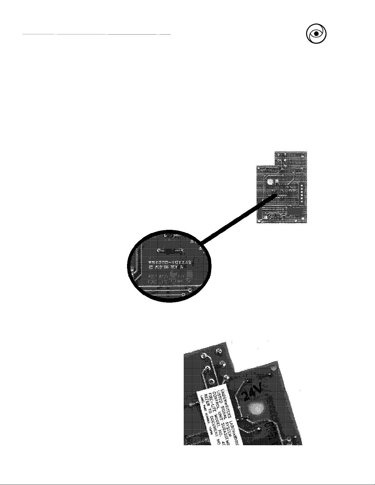
When received, the actual module boards will be marked as "MS4000 - 40xx" followed by a one letter
abbreviation and the letter "B" (
For instance:
To order a 24-volt General Alarm and Trouble Module, order a "4024AT".
The module received will be marked "MS4000 - 40xxAB."
for board
).
The voltage of a particular module is inked
on the bottom side of the PC board
6 15586 Rev E 5/14/93 P/N 15586:E
Page 7

1.0 Fire Alarm Control System
The MS-4012/4024 and CMS-4012/4024 are 4-zone fire alarm control panels designed for use in
commercial, industrial, and institutional applications. The 4012 is designed for 12-volt (nominal) devices.
The 4024 is designed for 24-volt (nominal) devices. Activation of any compatible two wire detector or any
normally open initiating device will sound audible devices, annunciate a fire zone, trip a municipal box,
notify a remote station and activate supplementary relay(s).
1.1 Standard features include:
✓✓
✓ 4 Class B (Style B) initiating zones
✓✓
✓✓
✓ 2 Class B (Style Y) indicating circuits
✓✓
✓✓
✓ Normally closed supervisory zone
✓✓
✓✓
✓ Power limited initiating and indicating loops
✓✓
✓✓
✓ Walk test feature with indicator
✓✓
✓✓
✓ Disable switches per initiating zone
✓✓
✓✓
✓ Resettable regulated power for 4-wire smoke detectors
✓✓
✓✓
✓ Current limited float type charger for sealed batteries
✓✓
✓✓
✓ Battery supervision
✓✓
✓✓
✓ Ground fault indicator
✓✓
✓✓
✓ Extensive transient protection
✓✓
✓✓
✓ Single Form-C general alarm contact
✓✓
✓✓
✓ Supervision of option boards
✓✓
✓✓
✓ Conversion of Zone 4 to a N.O. sprinkler supervisory
✓✓
✓✓
✓ Waterflow Alarm Service, including two zone waterflow plates (4000 WF) that
✓✓
mechanically lock the disable switch on waterflow zones.
1.2 Optional features include:
Transmitter Module (40xxTM) with reverse polarity alarm and trouble outputs, supervised
✓✓
✓
✓✓
output for local energy municipal box, and transmitter disable switch with indicator.
General Alarm and Trouble Module (40xxAT) that provides one Form-C general alarm
✓✓
✓
✓✓
contact with disable switch and one Form-C dry trouble contact with visual trouble indicator.
Zone Relay Module (40xxZR) that provides a Form-C alarm contact by zone, Form-A
✓✓
✓
✓✓
general alarm contact and Form-C trouble contact.
LED Annunciator Interface Module (40xxLI) for use with a remote zone annunciator (type
✓✓
✓
✓✓
RZA-4).
15586 Rev E 5/14/93 P/N 15586:E 7
Page 8
2.0 Controls and Indicators
2.1 Control Switches
Trouble Silence switch will si-
lence an audible trouble device.
The system trouble LED and the
trouble contact will remain activated until the trouble has been
corrected. If trouble silence switch
is still engaged when trouble is
cleared, audible device will resound.
System Test switch while held
down will energize an audible
trouble device and will light all indicators except the zone alarm
LEDs. Upon release of the switch,
all zones will go into alarm mode
and the supplementary relay(s) will
ALARM
TROUBLE
ALARM
TROUBLE
ALARM
TROUBLE
ALARM
TROUBLE
DISABLE
DISABLE
DISABLE
DISABLE
FIRE ALARM CONTROL
ZONE
1
ZONE
2
ZONE
3
ZONE
4
AC
POWER
SYSTEM
ALARM
SUPERVISORY
SYSTEM
TROUBLE
IND. CIRC.
TROUBLE
BATTERY
TROUBLE
GROUND
FAULT
WALK
TEST
SYSTEM
RESET
TROUBLE
SILENCE
SYSTEM
TEST
WALK
TEST
be activated.
Figure 2A: Dress Panel
Note: The Supervisory LED may not light during System Test, depending on whether or not Zone 4 is
programmed for supervisory service. To test the Supervisory LED, remove the jumper across Terminals 9
and 10, creating a supervisory condition. If the LED lights, it is good.
Walk Test switch allows one person to test all initiating an indicating devices. The function of this switch is
to automatically reset the panel. After receiving an alarm signal, the panel will sound all signaling devices
for two seconds and then will reset the panel. The procedure repeats every two to three seconds until the
alarm condition is cleared.
Disable switch (per initiating zone) prevents the sounding of alarm indicating devices in response to an alarm
condition on that zone. Zone and system trouble LEDs light and the audible trouble device sounds when a
respective zone is disabled. Zone alarm LED continues to indicate any alarm condition on disabled zone.
Note: The alarm and trouble contacts on the optional zone relay
module (40xxZR) are NOT disabled by the zone disable switch.
8 15586 Rev E 5/14/93 P/N 15586:E
Page 9

2.2 Status Indicators
A.C. Power - A green LED that remains on while the A.C. power supply is operating. If this indicator fails to light
under normal conditions, service the system immediately.
System Alarm - A red LED that lights when an alarm condition is detected.
Supervisory - A yellow LED that indicates need for action in connection with the supervision or maintenance
of sprinklers, extinguishing systems or other protective systems.
System Trouble - This yellow LED indicates that a fault or abnormal condition exists and that the fire alarm
system may be inoperative.
Ind. Circuit Trouble - A yellow LED that lights in response to a fault in the main bell circuits, including an open
or a short in the field wiring, or connection of a non-polarized indicating appliance.
Battery Trouble - A yellow LED that annunciates fault in the battery circuit.
Ground Fault - A yellow LED that lights when either side of the power source is shorted to the chassis.
Walk Test - A yellow LED that lights when the Walk Test feature is activated.
Zone Alarm - A red LED that lights when its associated zone is in alarm. The zone disable does not affect this
annunciator.
Zone Trouble - A yellow LED that lights when its associated zone has a fault or abnormal operating condition.
This trouble circuit monitors an initiating loop, local and remote zone alarm indicators, and the position of the
zone disable switch .
15586 Rev E 5/14/93 P/N 15586:E 9
Page 10
3.1 General
Carefully unpack the system and check for shipping damage. Mount the cabinet in a clean, dry, vibration-free
area in which extreme temperatures are not encountered. The location should be readily accessible with
sufficient room for easy installation and maintenance. Locate the top of the cabinet approximately five feet
above the floor with the hinge mounting on the left. Determine the number of conductors required for the
devices to be employed. Pull required conductors into the box through the knockout provided. All wiring should
be in accordance with the National and/or Local codes for fire alarm systems.
3.0 Installation Instructions
3.2 Initiating Circuits
Zones - Wire all alarm initiating devices sequentially for
proper supervision. Initiating devices include: coded and noncoded pull stations; heat, photoelectric, and ionization type
detectors; and waterflow alarm devices.
NOTE: To employ coded manual pull stations, inhibit the
latching circuit for a particular zone by removing the associated diode in the zone circuit on the main board (see Figure
3L).
Observe polarity when connecting polarized devices. Connect first device to the panel, second device to the first device,
third to the second and so on. Remove the End-of-Line
resistor (ELR) from the terminals and install on the terminals
of the last device. Wire the zones to the panel as shown in
Figures 3A and 3B.
Supervisory Circuit (Normally Open) - Zone 4 can be programmed to function as a normally open
supervisory zone. A short across the loop will light the zone alarm and supervisory LEDs, and will activate
an audible trouble device that can not be silenced and will sound until the panel is returned to normal. An open
in the wiring will light zone and system trouble LEDs, and the audible trouble device will sound. In this mode,
the audible device can be silenced. Remove jumper plugs JP5, JP6 and install JP7 and JP8. Connect normally
open contacts to Zone 4 terminals with an ELR across the last device.
Supervised Class B Operation
ELR
Smoke Detector
Heat Detector
Manual Station
Smoke Detector
Figure 3A: Zone Wiring
10 15586 Rev E 5/14/93 P/N 15586:E
Page 11

+ - +
Figure 3B: Dress Panel Terminal Guide
Waterflow - For waterflow service without a disable capability, the 4000WF can be employed. This adhesive-
backed metal plate can be affixed to the front dress panel over any zone used for monitoring sprinkler waterflow
detection devices. The plate mechanically locks the disable switch in the enable position so that it cannot silence
a waterflow alarm. To install, push the zone disable switch into the up (enable) position. Remove the adhesive
backing from the 4000WF plate and place it over the dress panel so that the switch protrudes through the plate.
✍✍
✍
NOTE: This option must not be used on Zone 4 if that
✍✍
zone is programmed for sprinkler supervisory service.
See the Device Compatibility Document for compatible, UL listed detectors available from Fire Lite.
3.3 Output Circuits
Indicating (Bell) Circuits - Two Class B Indicating Appliance Circuits are provided as a standard feature on
this panel. Each circuit is capable of 1.5 amperes of signaling current. Total current drawn from both circuits
cannot exceed 2.5 amperes. Indicating appliances must be polarized. Remove ELR from each circuit and install
after the last device connected to its respective circuit (see Figures 3B and 3C).
Indicating
Circuit
Polarized Polarized Polarized
Horn Light Bell
End of Line Resistor
10K 1/4-watt
Figure 3C: Indicating Circuit Wiring Diagram
Alarm Relay - One Form-C dry supplementary alarm contact is provided in the basic panel for controlling
supplementary devices. It is rated for 2 amps of current at 30 VDC and 0.5 amps at 30 VAC (resistive). See
Figure 3B for terminal location.
15586 Rev E 5/14/93 P/N 15586:E 11
Page 12

3.4 Power
Smoke Detector Power - Resettable power for 4-wire photoelectric and ionization smoke detectors can be
obtained from terminals 19 (negative) and 20 (positive). Up to 200mA of current is available, depending on
the number of optional modules in the system (see Appendix B: Table B-2 ).
Non-resettable Power - Non-resettable power can be drawn from Terminal Block 3. Power obtained from
TB3 must be subtracted from available Smoke Detector Power.
Resettable Power is to be drawn from the control panel, limit combined current to 50 mA.
CAUTION: Several different sources of power can be connected to this panel.
Disconnect all sources of power before servicing. The panel and associated
equipment may be damaged by removing and/or inserting cards, modules, or
interconnecting cables while this unit is energized.
Note: If both Smoke Detector and Non
20 (+)
19 ( - )
Unregulated, Unfiltered Power: Devices such as door holders requiring such DC power, up to 200 mA for
door holders, can be connected to terminal #18(+) and 19(-). See Figure 3B for terminal location.
Smoke Detector Power
Zone Loop
Smoke Detector Power
Figure 3D: Typical End of Line Relay ConnectionFigure 3D: Typical End of Line Relay Connection
Figure 3D: Typical End of Line Relay Connection
Figure 3D: Typical End of Line Relay ConnectionFigure 3D: Typical End of Line Relay Connection
End of Line Resistor
Last device
on zone
Listed End of Line Relay
Contacts shown in
energized position.
AC Power - Primary power required for this panel is
120 VAC, 60 Hz, 1.2 amperes. Overcurrent protection for this circuit must comply with Article 760 of
the National Electrical Code (NEC) and/or local
codes. Use #14 AWG or larger wire with 600 volt.
Connect AC power to panel terminals as illustrated
in Figure 3E.
Neutral
Hot
Figure 3E: AC Connections
12 15586 Rev E 5/14/93 P/N 15586:E
CAUTION
HIGH
VOLTA GE
Page 13

Battery Power - Observe polarity when connecting battery. Connect battery to P2 on the main board using
the plug-in connector provided. See Appendix B for calculation of correct battery rating. See Figure 3F for
battery connections.
CAUTION: Battery contains sulfuric acid which can cause severe burns to the skin
and eyes, and can destroy fabrics. If contact is made with sulfuric acid, immediately
flush skin or eyes with water for 15 minutes and seek immediate medical attention.
Ammeter - To monitor charging current, employ a zero-centered meter with a minimum range of 4 - 0 - 4.
Remove jumper JP2 and connect meter to plug P6 (see Figure 3F).
Voltmeter - To monitor the charger output voltage, use a voltmeter with a range of 0 - 50 VDC. Connect the
meter to plug P5 (see Figure 3F).
Zero-Centered Ammeter
Figure 3F: Battery and Meter Connections
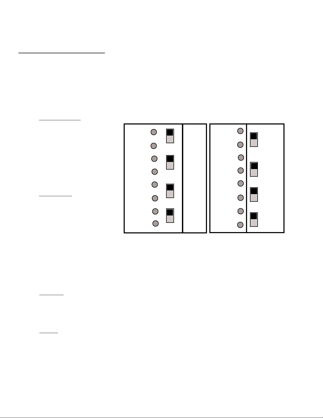
3.5 Optional Modules
The 4012/4024 has two module connectors - P3 and P4. Four modules are available for the panel, and they
can only be used in the combinations described below.
Connector P3 OR
Connector P4 OR
To Battery
(4 to 9 amp-hour)
Zone Relay Module (40xxZR)
LED Interface (40xxLI)
General Alarm and Trouble Module (40xxAT)
Transmitter Module (40xxTM)
Voltmeter
15586 Rev E 5/14/93 P/N 15586:E 13
Page 14

Remote Zone Annunciator (RZA-4) - This option provides remote LED annunciation of zone alarms and
system trouble status. It includes an audible trouble device with a trouble silence switch. To make use of this
remote function, an LED interface board (40xxLI) must be used. The 40xxLI module is supervised for insertion
(once JP3 is removed from the main board). If the 40xxLI is then removed, all four zone trouble LEDs and the
system trouble LED will come on, and the panel's audible trouble device sounds. All wiring except audible
trouble is supervised for opens and ground faults. The 4012/24 can power only one annunciator.
To install:
* Remove jumper JP3 on the main board.
* Plug the 40xxLI into connector P3 on the main board. Note that either this module or a Zone
Relay Module (40xxZR) may be plugged into P3, but not both.
* Connect the RZA-4 to the 40xxLI as illustrated in Figure 3G below.
Connect
to
P3
on Main
Board
To RZA-4
Terminal #:
RZA-4
Terminals
RZA-4 Schematic
Note: For unused zones on the RZA-4, jumper
corresponding terminal(s) on the 40xxLI to
Terminal 1(+12/24 volts). For instance, if
Zones 3 and 4 are not to be used on the RZA4, jumper Terminals 4 and 5 on the 40xxLI to
Terminal 1 on the 40xxLI.
1 2 3 4 5 6 7 8 9
Figure 3G: 40xxLI - Remote Zone Annunciator (RZA-4) Installation
14 15586 Rev E 5/14/93 P/N 15586:E
Page 15

Zone Relay Module (40xxZR) - One Form-C dry alarm contact per zone, one Form-A general alarm contact,
one Form-C trouble contact are provided with this option. The module is supervised for insertion (once jumper
JP3 on the main board is cut). If the 40xxZR is then removed, all four zone trouble LEDs and the system trouble
LED will come on, and the panel's audible trouble device sounds. Contacts are rated for 2.0 amps at 30 VDC
and 0.5 amps at 120 VAC. For applications requiring ULC listing, these contacts shall be derated to 2.0 amps
at 30 VDC and 0.5 amps at 30 VAC.
To install, remove jumper JP3 on the main board (Zone Alarm relays will NOT operate with JP3 installed). Plug
the module into connector P3 on the main board. Note that either this module or the LED Interface Board
(40xxLI) can be plugged into P3, but not both. Screw terminal connections are provided with each contact (see
Figure 3H).
The Zone Disable and Trouble Silence switches will not affect operation of the relays on the 40xxZR
module.
General
Alarm
Contact
Zone 1
Zone 2
Zone 3
Zone 4
System
Trouble
Note 1: Pin 2 is a Form-B general alarm contact. This pin provides a Normally Closed contact that will open only when ALL four
Note 2: Zone 4 alarm contacts WILL operate if Zone 4 is programmed as a supervisory zone.
zones are in alarm.
Figure 3H: 40xxZR Zone Relay Module Connections
15586 Rev E 5/14/93 P/N 15586:E 15
Page 16

General Alarm and Trouble Module (40xxAT)- This module provides one Form-C general alarm contact
and a system trouble contact. An Auxiliary Disable switch disables the alarm contact and creates a system
trouble condition. A yellow LED indicates when the switch is in the disable position. This module is supervised
for insertion (once jumper JP4 on the main board is cut). If the 40xxAT is then removed, the system trouble
LED will light and the panel's audible trouble device will sound.
Contacts are rated for 2.0 amps at 30 VDC and 0.5 amp at 120 VAC. For applications requiring ULC listing,
these contacts shall be derated to 2 amps at 30 VDC and 0.5 amps at 30 VAC.
To install, remove jumper JP4 on the main board. Plug the module into connector P4 through the standoff.
Secure the board to the main board using two screws provided. Note that either this module or a Transmitter
Module (40xxTM) may be plugged into P4, but not both.
Trouble
Alarm
Figure 3I: 40xxAT General Alarm and Tr o ub le Module Connections
16 15586 Rev E 5/14/93 P/N 15586:E
Page 17

Transmitter Module (40xxTM) - Use this module to connect to a local energy municipal box. Reverse polarity
alarm and trouble outputs are also provided. The reverse polarity alarm and municipal box outputs can be
disabled via a switch. A yellow LED indicates when the switch is in the disable position. The module is
supervised for insertion (once JP4 on the main board is removed). If the 40xxTM is then removed, the system
trouble LED will light and the panel's audible trouble device sounds. To install, remove jumper JP4 on the main
board. Plug this module into connector P4 and secure with the screws provided.
Municipal Box Output +
(alarm polarity shown) ALARM + in Normal - in Alarm
OUTPUT - in Normal + in Alarm
TROUBLE - in Normal + in Trouble
OUTPUT + in Normal - in Trouble
Figure 3J: 40xxTM Transmitter Module Connections
** Local Energy Municipal Box (supervised circuit): Remove jumper JP1. If box is equipped
with a reset supervisory switch, remove jumper between main board terminals 9 and 10 (see
Figure 3B). Wire the switch common to terminal 9 and the N.C. contact to terminal 10.
** Remote Station Connection (non-supervised): Terminals 3 and 4 provide a reverse
polarity alarm output. Trouble signals can be transmitted on these same terminals by cutting
jumper JP2 on the module (output voltage drops to zero (0) VDC during trouble unless overriden
by an alarm condition).
Note: This panel is suitable for use as a remote station where separate transmission circuits
are required for fire and trouble. To implement this feature, leave JP2 intact, use terminals 3
and 4 for alarm only, and terminals 5 and 6 for the reverse polarity trouble output.
15586 Rev E 5/14/93 P/N 15586:E 17
Page 18

McCulloh Transmitter - A McCulloh-type transmitter may be connected to the 4012/4024 (see Figure 3K for
connection of a model ATTE-B transmitter). The transmitter is mounted in a separate cabinet. Note that a General
Alarm and Trouble Module (40xxAT) is required to use the transmitter. NOTE: Be sure to derate available signaling
power by the transmitter coil current.
ATTE-B 40xxTM 4012/4024
Terminal Module
3 19
4 4
5 19
6 5
7 19
8 20
For more information on the ATTE-B,
consult "Bulletin 669" available
from Potter Electric Signal Company.
Figure 3K: ATTE-B McCulloh-Type Transmitter ConnectionFigure 3K: ATTE-B McCulloh-Type Transmitter Connection
Figure 3K: ATTE-B McCulloh-Type Transmitter Connection
Figure 3K: ATTE-B McCulloh-Type Transmitter ConnectionFigure 3K: ATTE-B McCulloh-Type Transmitter Connection
** Alarm Operation - During an alarm condition, the control panel will actuate the transmitter and cause the unit to transmit the
following:
- Four rounds of coded signal if the control panel is in a normal state.
- Three rounds of coded signal if the control panel is in a trouble state.
The transmitter's red LED will light during an alarm. When the alarm has cleared, reset the panel to reset the transmitter.
** Trouble Operation - During a trouble condition, the control panel will actuate the transmitter and cause the unit to transmit
one round of coded signal. The transmitter's yellow LED will light during trouble conditions. After the trouble condition in the
control panel has been cleared, press the Reset switch on the ATTE-B to remove the transmitter from a trouble state.
3.6 Central Station Service
The 4012/4024 can be employed as a Central Station Protected Premise Control Unit under the following conditions:
✓✓
✓ The control unit is used in conjuction with a compatible electrically actuated transmitter, UL listed for central
✓✓
station fire service under classification UUTV (Potter Electric Signal Company model ATTE-B)
✓✓
✓ The central station receiving unit must be UL listed and compatible with the transmitter.
✓✓
✓✓
✓ The transmitter must be installed according to its installation instructions.
✓✓
✓✓
✓ The transmitter cabinet must be mounted adjacent to the control unit with interconnecting wiring enclosed in
✓✓
conduit.
✓✓
✓ The fire alarm control unit, transmitter, and receiver are required to have at least 24-hour standby operating
✓✓
power.
18 15586 Rev E 5/14/93 P/N 15586:E
Page 19

Indicating Appliance Circuits: Class B operation. Power limited circuitry.
2.5 amps max (1.5 amps/circuit). 1.2 mA in normal. ELR = 10 K, 1/4 watt. Must
use polarized indicating appliances.
Initiating Device Circuits: Class B operation. 2.0
mA per loop. Power limited circuitry.
ELR - 2.2K, 1/4-watt (4012); 4.7K, 1/4 watt (4024)
Heat Detector
Manual Station
Smoke Detector
Ground
120 VAC
60 Hz
1.2 Amps
Ground
Dry supplementary alarm contact. Rated 2 amps @ 30
VDC and 0.5 amps @ 30 VAC (resistive).
DC power for external devices.
Power limited (see Section 3.4).
Unfiltered, unregulated, 1 amp max
(subtract from indicating circuit power).
Four-wire detector power
(up to 200 mA max, refer to
Appendix D). If non-resettable
power is used, limit combined
current to 50 mA.
Non-resettable
Power
(up to 50 mA max).
Subtract from Fourwire detector power.
Refer to Appendix D.
Plug TM or AT
module in P4
and cut JP4
Inhibit
latching
circuit by
removing
diode in
associated
zone:
D31 (Zone 1)
D33 (Zone 2)
D35 (Zone 3)
D37 (Zone 4)
Connect
Transformer
to P1
Remove JP5 and JP6
then install JP7
and JP8 for normally
open supervisory
service on Zone 4.
Zero-centered Ammeter
Plug LI or ZR
module in P3
and cut JP3
Cut JP4
when TM or
AT module is
employed
Cut JP2 when
ammeter is
employed
Voltmeter
Battery
(4-9 amp-hour)
PS-1242 or PS-1279
Figure 3L: Basic System Wiring Diagram
15586 Rev E 5/14/93 P/N 15586:E 19
Page 20

To insure proper and reliable operation, it is recommended that an inspection and testing of the system be
conducted monthly, or as required by National and/or Local codes. Testing should be performed by a qualified
service representative.
4.1 Notification
Before testing the panel, notify:
** Fire department and/or the central station receiving any transmitted alarm or trouble condition. If it is
necessary to inhibit alarm transmission, slide the remote station disable switch to its abnormal position.
** Facility personnel so that the alarm sounding devices will be ignored during the test period.
4.2 System T est
Slide the System Test switch down and ensure that all indicators except the zone alarm LEDs light and that
all signaling devices are active. Release the switch and ensure that all zone alarm LEDs light. Reset the panel.
4.3 Zone Test
Test a zone by shorting the zone contacts with a jumper. Ensure that the signaling devices are activated and
that the zone and system alarm LEDs light. Reset the panel and repeat for each zone.
4.0 Periodic Testing
4.4 Walk T est
To check all initiating devices, slide the Walk Test switch down. The Walk Test LED will light and the system
trouble devices will be activated. In this mode, the panel will reset automatically. Activate an alarm initiating
device and ensure that the indicating devices function. Check each initiating device in this manner. When all
initiating and indicating devices have been checked, return the Walk Test switch to its normal position.
4.5 Supervisory Test
When the fourth zone is programmed to monitor normally open supervisory devices, a contact closure across
the loop will light the supervisory and zone alarm LEDs and will sound the audible trouble device. In this state,
the audible device will continue to sound regardless of the position of the trouble silence switch. An open in
the loop will light zone and system trouble LEDs and will sound the audible device.
20 15586 Rev E 5/14/93 P/N 15586:E
Page 21

4.6 T rouble T est
Momentarily open the following circuits, one at a time, and check for a trouble signal:
❑❑
❑ Indicating Appliance Circuits 1 and 2
❑❑
❑❑
❑ All initiating zones
❑❑
❑❑
❑ Supervisory circuit
❑❑
❑❑
❑ Municipal Box (if employed)
❑❑
4.7 Battery T est
With fully charged battery, remove AC power and repeat the test procedure outlined in Section 4.2. Measure
battery voltage while the indicating appliances are activated. Reapply AC power and reset the panel. Replace
any battery with terminal voltage less than 85% of rating.
4.8 T est Completion
At the conclusion of testing, return all switches to their normal (up) positions. Notify the fire department, central
station and facility personnel that the test is complete.
15586 Rev E 5/14/93 P/N 15586:E 21
Page 22

Troubleshooting is divided into two parts. Section 5.1 is a diagnostic procedure that can be used to determine
the general condition of the control panel. Section 5.2 is to be used by QUALIFIED SERVICE PERSONNEL
ONLY to isolate a specific problem with the panel.
5.1 Control Panel Checkup
This procedure must be used after initial installation of the control panel. The procedure should also be
followed after any repairs are made to the panel. Follow the procedure step by step until the problem is
eliminated or all tests have been completed. Remove both sources of power from this unit whenever working
with the unit's terminals, modules, or plugs.
Jumpers - Ensure that jumpers JP2-JP8 and Diodes D31, D33, D35, and D37 are programmed in accordance
with the guidelines below. Refer to Figure 3L for jumper and diode locations.
* JP2 is cut only when an ammeter is employed.
* JP3 is cut only when a 40xxLI or 40xxZR is being used.
* JP4 is cut only when a 40xxTM or 40xxAT is being used.
* For normally open supervisory service on Zone 4, JP7 & JP8 must be installed and JP5 and JP6 must be
removed. For normal operation on Zone 4, JP5 & JP6 must be installed and JP7 & JP8 removed.
* For coded output, inhibit the alarm latching circuit on an initiating zone by cutting its respective diode: D31-
Zone 1; D33-Zone 2; D35-Zone 3; D37-Zone 4.
5.0 Troubleshooting Guide
Reset - Disconnect the batteries. Remove AC power from the panel. Wait 30 seconds and reconnect AC
power first, followed by the batteries. This resets the panel's built-in fuses.
Isolate - To distinguish between a problem in the field wiring, disconnect all initiating and indicating loops and
reinstall the end-of-line resistors across the appropriate terminals. Jumper terminals 9 and 10 together.
Disconnect any wiring on terminals 15-20. If employing any of the optional modules, disconnect all wiring but
leave the modules in their appropriate connectors (P3 & P4). The only wires leading to the panel should be
the AC power connections. Refer to Figure 3L for ELR values.
If this action clears the problem, the trouble lies in the field wiring. To isolate
the problem, reconnect the wires one at a time until the problem reappears.
Remove one module at a time and reconnect the corresponding jumper (JP3 for 40xxLI or 40xxZR - and JP4
for 40xxTM or 40xxAT).
If this action clears the problem condition, the
trouble lies in the module. Replace the module.
Leave each module off to continue the testing.
22 15586 Rev E 5/14/93 P/N 15586:E
Page 23

System Test - Slide the system test switch down and ensure that all LEDs except the zone alarm LEDs light.
Release the switch and ensure that all alarm LEDs light. Note: The Supervisory LED may not light during
System Test, depending on whether or not Zone 4 is programmed for supervisory service. To test the
Supervisory LED, remove the jumper across Terminals 9 and 10, creating a supervisory condition. If the LED
lights, it is good.
If any LED fails to light or the audible trouble device fails
to sound, the panel must be repaired or replaced.
Conclusion - If the problem still exists, four conditions may prevail:
a) Main board has failed.
b) Power Supply (transformer) has failed.
c) Batteries have failed.
d) Combination of the above three.
If the AC led is on, the transformer can be eliminated as the source of
the problem. If the battery trouble LED is off (but passed the system test),
the batteries are not the source of the problem. If the batteries and
transformer are known to be good, have the panel repaired or replaced.
Problems concerning the AC power supply or the batteries are covered in Section 5.2.
5.2 Component Troubleshooting
QUALIFIED SERVICE PERSONNEL ONLY!
The test procedures in Section 5.1 must be conducted prior to conducting the
test in this section in order to accurately troubleshoot the control panel.
Battery Test (Battery Trouble Indication)
The batteries may be tested by conducting the procedure in Section 4.7.
Transformer Test (AC Power LED off)
Ensure that circuit breaker CB1 is not tripped. Measure the AC voltage applied to the transformer primary
winding (pins 5 & 7 on plug P1- see Figure 3L for plug locations). This voltage should fall in the range 102
- 132 VAC. Measure the transformer secondary voltage on plug P1 to determine if it falls within the following
specifications: P1 - Pins 2 & 3: 24 - 32 AC volts P1 - Pins 1 & 3: 12 - 16 AC volts
If the transformer secondary voltage does not
meet specifications, replace the transformer.
15586 Rev E 5/14/93 P/N 15586:E 23
Page 24

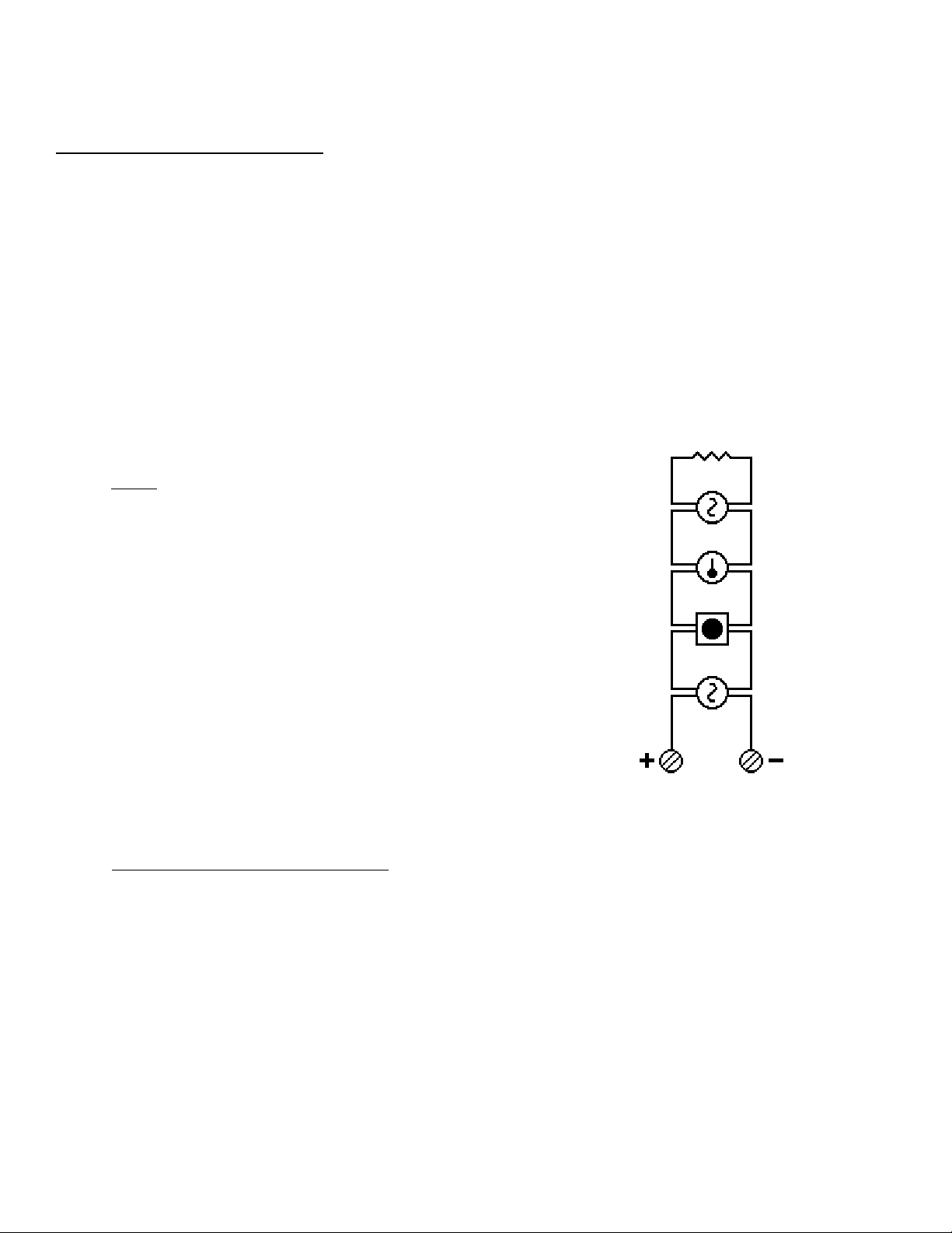
Charger Test, New Models (CMS-4012/4024s and newer model MS-4012/4024s only)
IMPORTANT! The Battery Charger Output cannot be field adjusted on CMS4012/4024 control panels and on newer revisions of the MS-4012/4024 control
panels. These panels are distinquished from earlier models by the addition of two
non-resettable power terminals (Terminal Block 3) in the upper right-hand part
of the control board. Any attempts to adjust this output may result in damage to
the batteries (to read and adjust the charger output on earlier model MS-4012/
4024s, see the next page).
The charger output can be read with a voltmeter to determine if the panel is
operating properly. To read the charger output, see Figure 3M: Battery Charger
Check Procedure. If the charger output voltage does not meet specifications (and
the transformer is known to be good), the control panel will have to be repaired
or replaced.
Step 1
Remove and save JP12 from the
control panel.
Newer 4012s and 4024s
contain TB3 (Nonresettable Power Output).
Step 2
Remove the batteries and place a 1k, 1watt resistor across the charger ouput
pins - P2, pin 1(+) and P2, pin 3 (-).
Step 3
Using a voltmeter, measure the DC voltage across the 1K resistor. This
voltage must be 13.2 - 13.3 on the 4012, or 27.5 - 27.7 on the 4024.
At the conclusion of the test, remove the voltmeter and 1K resistor,
replace the batteries, and reinstall JP12!
Figure 3M: Battery Charger Check Procedure
24 15586 Rev E 5/14/93 P/N 15586:E
Page 25

Charger Test, Older Models (Older Model MS-4012/4024s only)
Note: This procedure may result in destruction of the batteries if used on
CMS-4012/4024s and newer MS-4012/4024s that provide non-resettable power!
For MS-4012/4024s that do not provide non-resettable power, the battery charging circuit can be checked and
if neccessary, calibrated under the following procedure. Remove the batteries and place a 1k, 1-watt resistor
across the charger ouput pins [plug P2: pin 1 - (+), pin 3 (-) ]. Using a voltmeter, measure the DC voltage across
the 1K resistor. If the voltage measured is not 13.2 - 13.3 (4012) or 27.5 - 27.7 VDC (4024), perform the
following calibration procedure:
Step 1 Adjust R5 until the voltage across the 1K resistor is 30 VDC (MS-4024) or 15 VDC (MS-4012).
Step 2 Adjust R108 until the the Battery Trouble LED just turns on (threshold point).
Step 3 Adjust R5 until the voltage across the resistor is 27.6 VDC (MS-4024) or 13.2 VDC (MS-4012).
Step 4 Remove the meter and resistor and reconnect the batteries to Plug P2.
If this adjustment fails to bring the charger voltage to within the specified range,
or fails to extinquish the battery trouble indication, (and the transformer and
batteries are known to be good), have the panel repaired or replaced.
15586 Rev E 5/14/93 P/N 15586:E 25
Page 26

Appendix A: Specifications
A.1 Initiating Circuits
Power-limited circuitry
Operation: Class B (Style B)
Standby voltage: 4012 = 12 VDC (ripple = 10mV peak-to-peak)
4024 = 24 VDC (ripple = 10mV peak-to-peak)
Alarm current: 15 milliamps minimum
Short circuit current: 35 milliamps typical
Maximum detector current in standby: 2 milliamps (peak) per zone
Maximum loop resistance = 200 ohms
End-of-line resistor: 4012 = 2.2K, 1/4-watt 4024 = 4.7K, 1-4-watt
Detector loop current is sufficient to ensure operation of one alarmed detector per zone.
Supervisory current: 5mA
A.2 Indicating Circuits
Power-limited circuitry
Maximum voltage drop due to wiring: 4012 = 1 VDC 4024= 2 VDC
Indicating device operating range: 4012 = 9 - 15 VDC 4024 = 18-31 VDC
Total current to all external devices: 2.5 amps
Maximum signaling current per circuit: 1.5 amps
End-of-line resistor = 10k, 1/4 watt
A.3 Alarm Relay
Dry Form-C contacts rated for: 2.0 amps @ 30 VDC (resistive)
0.5 amps @ 30 VAC (resistive)
A.4 AC Power
120 VAC, 60 Hz, 1.2 amps
Wire size: #14 AWG with 600V insulation
A.5 T ransmitter Module (40xxTM)
For local energy municipal box service
Output current: 1.2 mA (in normal).
Trip current: 0.35 amps.
Coil Voltage: 3.65 VDC.
Coil resistance: 14.6 ohms.
Total wire resistance between panel and trip coil = 3 ohms
For Remote Station service:
Output current shall not exceed 10 milliamps per circuit.
Reverse polarity output voltage: 4012 = 12 VDC 4024 = 24 VDC.
See Figure 3J for terminal information.
26 15586 Rev E 5/14/93 P/N 15586:E
Page 27

A.6 Zone Relay Module (40xxZR)
Contacts rated for: 2.0 amps @ 30 VDC (resistive) 0.5 amps @ 120 VAC (resistive)
Note: For U.L.C. applications, contacts are derated for: 2.0 amps @ 30 VDC (resistive)
0.5 amps @ 30 VAC (resistive)
A.7 General Alarm and Tr o ub le Relay Module (40xxAT).
Contacts rated for: 2.0 amps @ 30 VDC (resistive) 0.5 amps @ 120 VAC (resistive)
Note: For U.L.C. applications, contacts are derated for: 2.0 amps @ 30 VDC (resistive)
0.5 amps @ 30 VAC (resistive)
A.8 Four-wire Smoke Detector Power
Up to 200mA of current can be provided to four-wire smoke detectors. Note: If using Non-Resettable
power (Terminal Block 3), the combined current shall be limited to 50 mA.
A.9 Unregulated, Unfiltered Power
Total DC current available for powering external devices is 1.0 amp (subtracted from indicating appliance
power).
A.10 Non-resettable Power
DC current available from this output and four-wire smoke power output combined is 50mA.
A.11 Cabinet Dimensions
Door = 15-1/4"
Backbox = 15"
Cabinet = 2-7/8"
Backbox = 2-1/2"
Door = 14-3/4"
Backbox = 14-1/2"
15586 Rev E 5/14/93 P/N 15586:E 27
Page 28

Appendix B: Power Calculations
NOTE: The LED Interface (40xxLI) does not consume any power and can be ignored when calculating power
requirements. In addition, the General Alarm and Trouble Module (40xxAT) does not consume power during
trouble and the RZA-4 consumes nothing in alarm.
Table 1: Standby Battery Requirements
Basic Control Panel 79.2 mA
(AC Power off - System trouble LED on and audible trouble
sounder activated - includes indicating supervisory current)
If using a Zone Relay Module: 4012ZR, add 8 mA
or 4024ZR, add 16 mA
If using a Transmitter Module (40xxTM), add 5 mA
If using the Reverse Polarity Alarm output, add 10 mA
If using the Reverse Polarity Trouble output, add 10 mA
If using a Remote Zone Annunciator (RZA-4), add 8 mA
Unregulated, Auxiliary power (draw from Terminals 18 & 19)
Number Current Total
in Per Device
use Device Current
a. Two-wire detector heads
b. Four-wire detector heads
c. End of Line Relays
d. Add lines a, b, & c for subtotal
X 0.1 mA =
X 0.15 mA =
X 25.0 mA =
Place subtotal here
Add last column for Standby Battery Current :
☞☞
☞
☞☞
28 15586 Rev E 5/14/93 P/N 15586:E
Page 29

Table 2: Power Supply Loading
Basic Control Panel (all zones in alarm)
If using the Zone Relay Module, add
64 mA for the MS-4012 or 32 mA for the MS-4024
If using General Alarm & Trouble Module: add
18 mA for the MS-4012 or 10 mA for the MS-4024
If using the Transmitter Module (40xxTM), add 13 mA
If using the Reverse Polarity Trouble output, add 10 mA
Current (in mA) drawn from Non-resettable Power (TB3)
340 mA340 mA
340 mA
340 mA340 mA
Place subtotal from line d, Table 1 here
Add column for Total Alarm Current:
(Total Alarm Current cannot exceed 550 mA)
Table 3: Ampere-Hour Calculations
Standby Battery Current Standby Time
Convert the total from Table 1 24 or 60 hours
to amps and enter here
amps X hours =
Enter 0.3 for 5 minutes in alarm
or 0.6 for 10 minutes in alarm +
☞☞
☞
☞☞
Standby
amp/hours
Alarm
amp/hours
Add Standby and Alarm amp/hours =
Select a battery with a greater amp/hour rating.
Notes: * NFPA 72 Local and 72 Proprietary Protected Premises systems require 24 hours of standby.
* NFPA 72 Auxiliary and 72 Remote Station systems require 60 hours of standby.
* The battery charger in this panel will charge a maximum of 9 AH batteries within 48 hours (6 AH minimum).
(Batteries larger than 7-AH battery will have to be mounted in a separate cabinet adjacent to panel).
Batteries available from FireLite
PS-1242 4.2 AH @ 12 VDC (MS-4012 requires two)
PS-1270 7.0 AH @ 12 VDC (MS-4024 requires two)
15586 Rev E 5/14/93 P/N 15586:E 29
Total amp/hours
needed
Page 30

MS-4012/4024 Quick Reference Sheet
O
p
e
r
a
t
i
o
n
T
e
Alarm Condition:
Alarm Silence:
Alarm Reset:
Trouble Condition:
Action Result
Notify fire department, central station, and facility personnel of test.
Slide SYSTEM TEST switch down. ------------------ All LEDs (except zone alarm) light and
Release SYSTEM TEST switch. ---------------------- All zone alarm LEDs will light.
Short out each zone, one at a time. ---------------- Zone and system LEDs light. All indicating
1) The system alarm and zone alarm indicators will light.
2) Indicating appliances will be activated.
3) Supplementary output will be activated.
Locate alarmed zone and slide zone disable switch downward.
After correcting the alarm condition, reset the control panel by
depressing the SYSTEM RESET switch.
A trouble signal under normal operation indicates a condition
that requires immediate correction. Contact your local service
representative. The panel's audible trouble buzzer that sounds
in response to a trouble condition may be silenced by depressing
the TROUBLE SILENCE switch (the trouble LED will remain on).
indicating appliances are activated.
appliances are activated.
s
t
i
n
g
Name:
Address:
Slide WALK TEST switch down. --------------------- Walk Test LED and system trouble activated.
Activate alarm initiating ------------------------------- Zone alarm and system LEDs light. Indicating
devices, one at a time appliances are briefly activated then reset.
Slide WALK TEST switch up. ------------------------- Panel exits test mode and returns to normal.
Short out Zone 4 (if monitoring ---------------------- Supervisory and zone alarm LEDs light. Audible device
N.O. supervisory devices). continues to sound until trouble condition is corrected.
Open Zone 4 (if monitoring -------------------------- Zone and system trouble LEDs light and
N.O. supervisory devices). audible trouble device sounds.
Momentarily open all circuits, ----------------------- System and respective circuit trouble LEDs
one at a time. light. Audible trouble device sounds.
Remove AC power and conduct SYSTEM ------ Battery terminal voltage should be at nominal rating.
TEST again. Measure battery voltage.
Notify fire department, central station, and facility personnel that test is complete.
Local Service Representative
Telephone:
Cut out, frame and place this sheet adjacent to the control panel.
✄✄
✄
✄✄
Page 31

CMS-4012/4024 Quick Reference Sheet
O
p
e
r
a
t
i
o
n
T
e
Alarm Condition:
Alarm Silence:
Alarm Reset:
Trouble Condition:
Action Result
Notify fire department, central station, and facility personnel of test.
Slide SYSTEM TEST switch down. ------------------ All LEDs (except zone alarm) light and
Release SYSTEM TEST switch. ---------------------- All zone alarm LEDs will light.
Short out each zone, one at a time. ---------------- Zone and system LEDs light. All indicating
1) The system alarm and zone alarm indicators will light.
2) Indicating appliances will be activated.
3) Supplementary output will be activated.
Locate alarmed zone and slide zone disable switch downward.
After correcting the alarm condition, reset the control panel by
depressing the SYSTEM RESET switch.
A trouble signal under normal operation indicates a condition
that requires immediate correction. Contact your local service
representative. The panel's audible trouble buzzer that sounds
in response to a trouble condition may be silenced by depressing
the TROUBLE SILENCE switch (the trouble LED will remain on).
indicating appliances are activated.
appliances are activated.
s
t
i
n
g
Name:
Address:
Slide WALK TEST switch down. --------------------- Walk Test LED and system trouble activated.
Activate alarm initiating ------------------------------- Zone alarm and system LEDs light. Indicating
devices, one at a time appliances are briefly activated then reset.
Slide WALK TEST switch up. ------------------------- Panel exits test mode and returns to normal.
Short out Zone 4 (if monitoring ---------------------- Supervisory and zone alarm LEDs light. Audible device
N.O. supervisory devices). continues to sound until trouble condition is corrected.
Open Zone 4 (if monitoring -------------------------- Zone and system trouble LEDs light and
N.O. supervisory devices). audible trouble device sounds.
Momentarily open all circuits, ----------------------- System and respective circuit trouble LEDs
one at a time. light. Audible trouble device sounds.
Remove AC power and conduct SYSTEM ------ Battery terminal voltage should be at nominal rating.
TEST again. Measure battery voltage.
Notify fire department, central station, and facility personnel that test is complete.
Local Service Representative
Telephone:
Cut out, frame and place this sheet adjacent to the control panel.
✄✄
✄
✄✄
 Loading...