

Page 1

Page 2

Dear Customer,
Thank you for selecting Fiat and congratulations on your choice of a Fiat SEDICI.
We have written this handbook to help you get to know all your new vehicle features and use it in the best possible way.
You should read it right through before taking the road for the first time.
You will find information, tips and important warnings regarding the driving of your vehicle to help you derive the maximum from
your Fiat SEDICI technological features.
The enclosed Warranty Booklet lists the services that Fiat offers to its Customers:
❒
the Warranty Certificate with terms and conditions for maintaining its validity
❒
the range of additional services available to Fiat Customers.
Best regards and good motoring!
This Owner Handbook describes all Fiat SEDICI versions. As a consequence, you should consider only the
information which is related to the engine and bodywork version of the vehicle you purchased.
1
Page 3

FIAT ORIGINAL SPARE PARTS AND FIAT RE-CONDITIONED SPARE PARTS
FIAT ORIGINAL SPARE PARTS
These spare parts ensure the reliability
and technological quality needed to travel safely. Designed on the basis of the same
project of the components fitted on the
vehicle, the original spare parts undergo
very harsh tests before being produced or
re-conditioned, with the aim of being used
to keep the vehicle performance unchanged in time.
Therefore, for an accurate and careful
maintenance, choose Fiat original spare
parts (re-conditioned and non re-conditioned), which can be identified by the features of their package and which are available only at the Fiat Dealership.
By choosing Fiat original spare parts (reconditioned and non re-conditioned) you
can rely on a rapid and efficient service
provided by skilled operators, on good
equipment and a wide range of parts.
The Fiat Dealership uses Fiat original spare
parts and re-conditioned spare parts.
FIAT RE-CONDITIONED
SPARE PARTS
They are Fiat original spare parts/mechanical assemblies, already used but given back to Fiat, which renews them completely to meet the same qualitative and
reliability requirements of the newly original spare parts.
Fiat re-conditioned spare parts:
❒
give the Customers the opportunity to
buy spare mechanical assemblies (engines, transmissions, etc.) at particularly favourable prices;
❒
contribute to safeguard the environment by reducing scrapping operations
and the disposal of removed materials.
2
Page 4
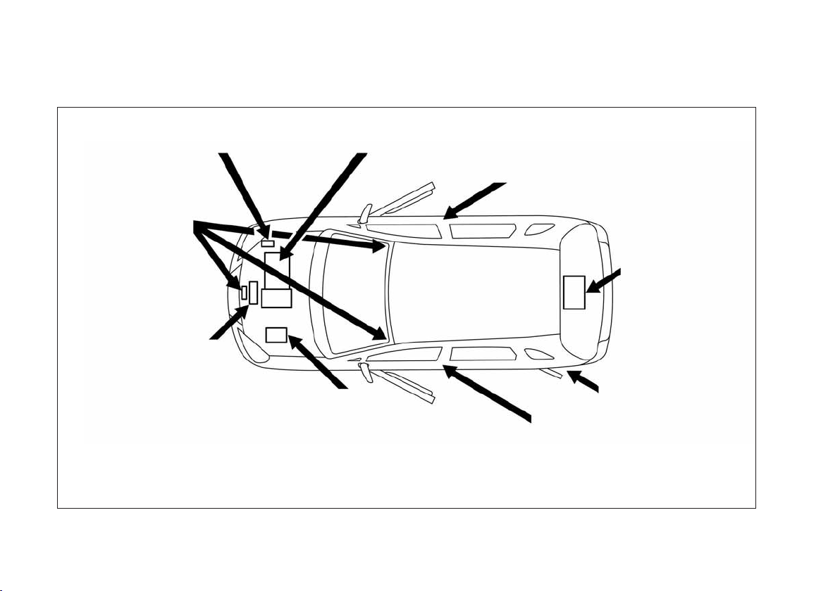
SERVICE STATION GUIDE
Windshield washer fluid
(See Section 8)
Engine hood
(See Section 4)
Engine oil and filter
(See Section 8)
Engine coolant
(See Section 8)
LHD: Left Hand Drive
RHD: Right Hand Drive
Engine oil dipstick (Yellow)
(See Section 8)
(RHD)
(LHD)
Battery
(See Section 8)
Tire pressure (RHD)
(See tire information label
on driver’s door lock pillar)
Tire changing tools
(See Section 4)
Spare tire
(See Section 8)
Fuel
(See Section 1)
Tire pressure (LHD)
(See tire information label on driver’s
door lock pillar)
79J090
3
Page 5
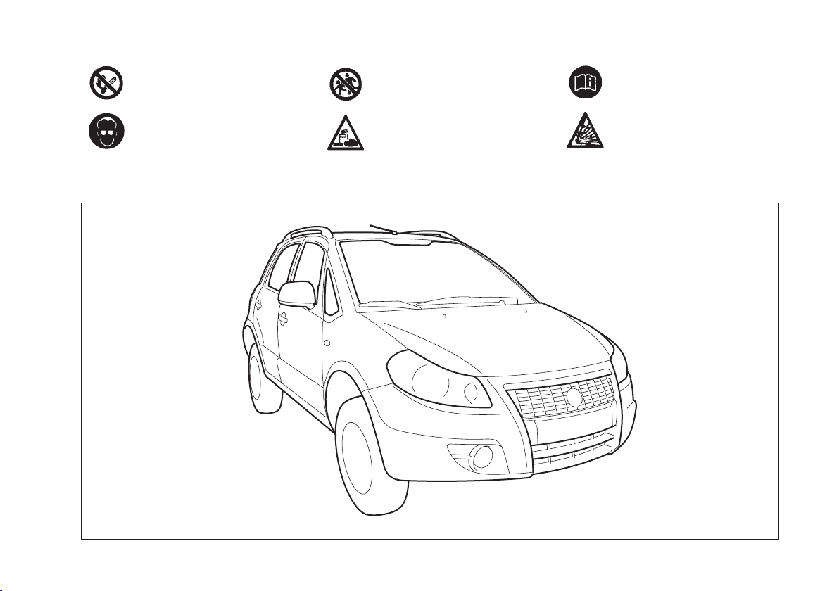
BATTERY LABEL SYMBOL MEANINGS
No smoking, no naked flames,
no sparks
Shield eyes
Keep away from children
Battery acid
Note operating instructions
Explosive gas
79J001
4
Page 6
FOREWORD
This manual should be considered a permanent part of the vehicle and should remain with the vehicle when resold or otherwise transferred to a new owner or operator. Please read this manual carefully
before operating your new Fiat and review
the manual from time to time. It contains
important information on safety, operation and maintenance.
All information in this manual is based on
the latest product information available at
the time of publication. Due to improvements or other changes, there may be discrepancies between information in this
manual and your vehicle. Fiat reserves the
right to make production changes at any
time, without notice and without incurring
any obligation to make the same or similar changes to vehicles previously built or
sold.
This vehicle may not comply with standards or regulations of other countries.
Before attempting to register this vehicle
in any other country, check all applicable
regulations and make any necessary modifications.
IMPORTANT
Please read this manual and follow its instructions carefully. To emphasize special
information, the symbol "and the words
WARNING, IMPORTANT and NOTE
have special meanings. These special
meanings apply except when laws or regulations require that the signal words be
used with a different meaning.
Pay special attention to the messages highlighted by these signal words:
WARNING
Indicates a potential hazard
that could result in death or
injury.
IMPORTANT Indicates a potential hazard
that could result in vehicle damage.
NOTE Indicates special information to
make maintenance easier or instructions
clearer.
5
Page 7
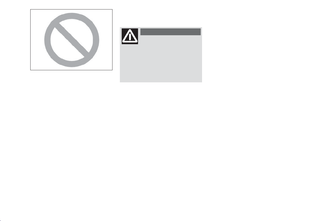
MODIFICATION WARNING
75F080
The circle with a slash in this manual
means “Don’t do this” or “Don’t let this
happen”.
WARNING
Do not modify this vehicle.
Modification could adversely affect safety, handling, performance, or durability and may violate
governmental regulations. In addition, damage or performance problems resulting from modification may
not be covered under warranty.
IMPORTANT Improper installation of
mobile communication equipment such as
cellular telephones or CB (Citizen’s Band)
radios may cause electronic interference
with your vehicle’s ignition system, resulting in vehicle performance problems.
Consult your Fiat Dealership or qualified
service technician for advice on installing
such mobile communication equipment.
6
Page 8

TTAABBLLEEOOFFCCOONNTTEENNTTS
S
BEFORE DRIVING
1
STEERING COLUMN CONTROLS
INSTRUMENT PANEL
OTHER CONTROLS AND EQUIPMENT
OPERATING YOUR VEHICLE
DRIVING TIPS
VEHICLE LOADING AND TOWING
INSPECTION AND MAINTENANCE
EMERGENCY SERVICE
BODY WORK CARE
GENERAL INFORMATION
TECHNICAL SPECIFICATIONS
2
3
4
5
6
7
8
9
10
11
12
SUPPLEMENT
INDEX
13
14
Page 9

Page left blank voluntarily.
Page 10
60G404
BBEEFFOORREEDDRRIIVVIINNG
FUEL RECOMMENDATION ............................................ 10
KEYS ........................................................................................ 11
DOOR LOCKS ..................................................................... 12
WINDOWS .......................................................................... 24
MIRRORS ............................................................................... 27
SEAT ADJUSTMENT ........................................................... 28
ADJUSTABLE HEAD RESTRAINTS (if equipped) ........ 30
SEAT BELTS AND CHILD RESTRAINT SYSTEMS ...... 31
SUPPLEMENTAL RESTRAINT SYSTEM
(air bags) (if equipped) ......................................................... 47
G
1
9
Page 11
FUEL
RECOMMENDATION
GASOLINE ENGINE
If your vehicle is not fitted with a restrictor
in the fuel filler pipe then you may use leaded or unleaded gasoline with an octane
number (RON) of 85 or higher.
Note, it is preferable to use unleaded gasoline.
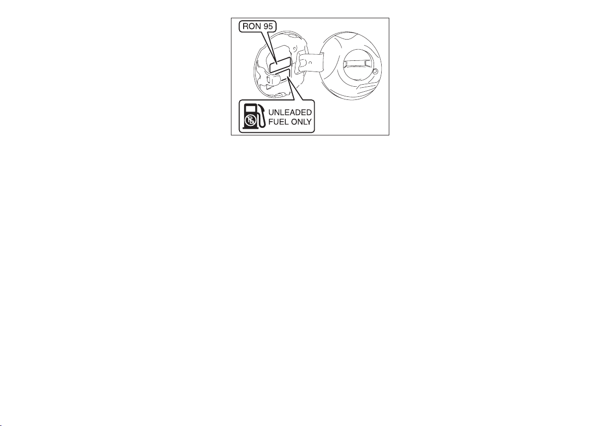
If your vehicle is fitted with a restrictor
in the fuel filler pipe then you must use unleaded gasoline with an octane number
(RON) of 91 or higher (or RON of 95 or
higher if it is stated on the fuel filler lid).
These vehicles are also identified by a label attached near the fuel filler pipe that
states: “UNLEADED FUEL ONLY”.
If the “RON 95” label is attached, you
must use unleaded gasoline with an octane
number (RON) of 95 or higher.
63J292
Gasoline/ Ethanol blends
Blends of unleaded gasoline and ethanol
(grain alcohol), also known as gasohol, are
commercially available in some areas.
Blends of this type may be used in your vehicle if they are no more than 10%
ethanol. Make sure this gasoline- ethanol
blend has octane ratings no lower than
those recommended for gasoline.
Gasoline/ Methanol blends
Blends of unleaded gasoline and methanol
(wood alcohol) are also commercially available in some areas. DO NOT USE fuels
containing more than 5% methanol under
any circumstances. Fuel system damage or
vehicle performance problems resulting
from the use of such fuels are not the responsibility of Fiat and may not be covered
under the New Vehicle Warranty.
Fuels containing 5% or less methanol may
be suitable for use in your vehicle if they
contain cosolvents and corrosion inhibitors.
NOTE If you are not satisfied with the driveability or fuel economy of your vehicle
when you are using a gasoline/ alcohol
blend, you should switch back to unleaded gasoline containing no alcohol.
IMPORTANT Be careful not to spill fuel
containing alcohol while refueling. Fuels
containing alcohol can cause paint damage,
which is not covered under the New Vehicle Limited Warranty.
DIESEL ENGINE
The diesel fuel should be with Cetane Index higher than 50 and sulfur content less
than 50 ppm (parts per million). You
should use the diesel fuel conformable to
EN590 that corresponded to Euro IV
emission control. Do not use marine
diesel fuel, heating oils and so forth. If you
use improper diesel fuel, it may cause serious engine damage.
10
Page 12
IMPORTANT The vehicle must only be
filled with diesel fuel for motor vehicles,
in compliance with European Standard
EN590. The use of other products or mixtures may irreparably damage the engine
with invalidation of the warranty due to
the damage caused. In the event of accidentally filling with another type of fuel, do
not start the engine and empty the tank.
If the engine has been run even for only a
very short time, in addition to the tank,
it is also necessary to drain out the whole
fuel circuit.
IMPORTANT The fuel tank has an air
space to allow for fuel expansion in hot
weather. If you continue to add fuel after
the filler nozzle has automatically shut off
or an initial blowback occurs, the air
chamber will become full. Exposure to
heat when fully fuelled in this manner will
result in leakage due to fuel expansion. To
prevent such fuel leakage, stop filling after the filler nozzle has automatically shut
off, or when using an alternative non automatic system, initial vent blowback occurs.
WARNING
Do not put naked flames or
lighted cigarettes near the
fuel filler hole as there is a danger of
fire. Do not bend too close to the hole
either so as not to breathe in harmful
vapours.
KEYS
Your vehicle comes with a pair of identical keys. One key can open all of the locks
on the vehicle. Keep the spare key in a safe
place.
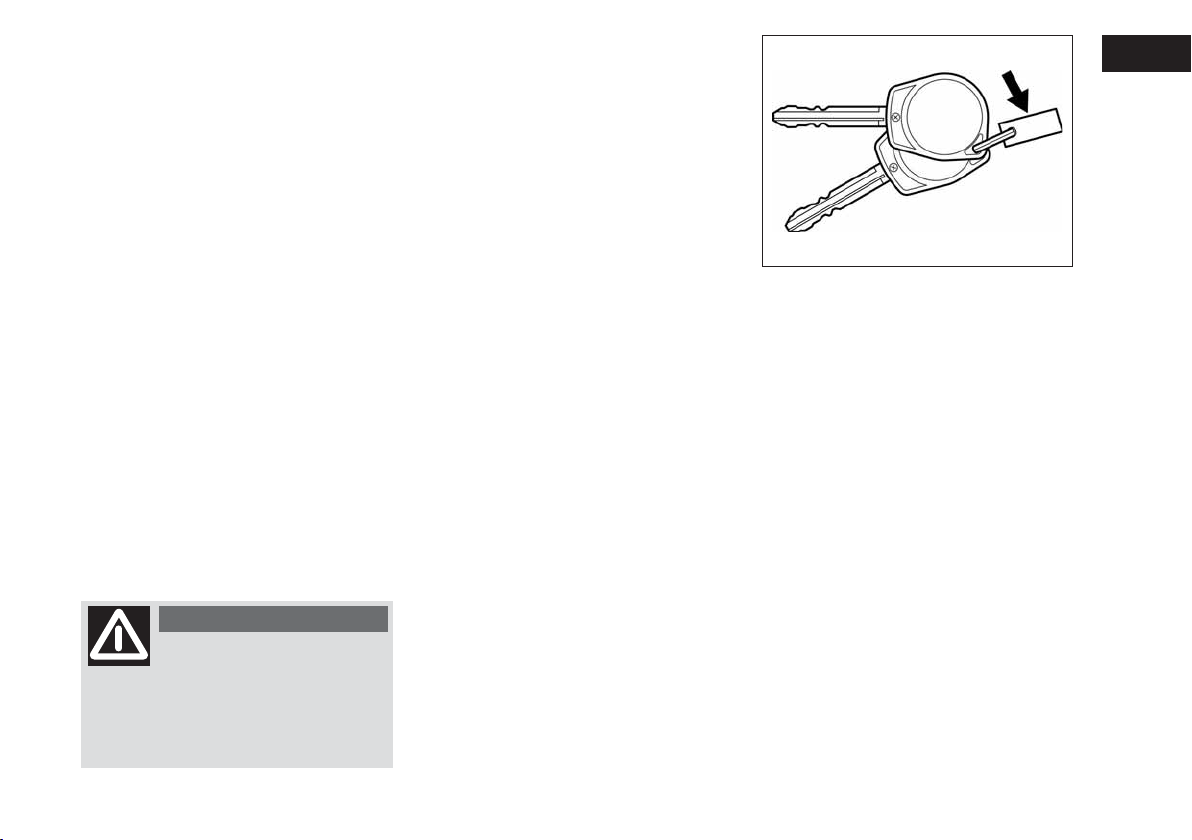
The key identification number is stamped
on a metal tag provided with the keys or
on the keys. Keep the tag (if equipped) in
a safe place. If you lose your keys, you will
need this number to have new keys made.
IMPORTANT All the keys and the metal
tag must be handed over to the new owner when selling the vehicle.
79J020
Fiat CODE - Immobilizer System
(if equipped)
This system is designed to help prevent
vehicle theft by electronically disabling the
engine starting system.
The engine can be started only with your
vehicle’s original immobilizer ignition key
which has an electronic identification code
programmed into it. The key communicates the identification code to the vehicle when the key is turned to the “ON”
position. If you need to make spare keys,
see your Fiat Dealership. The vehicle must
be programmed with the correct identification code for the spare keys. A key
made by an ordinary locksmith will not
work.
11
Page 13
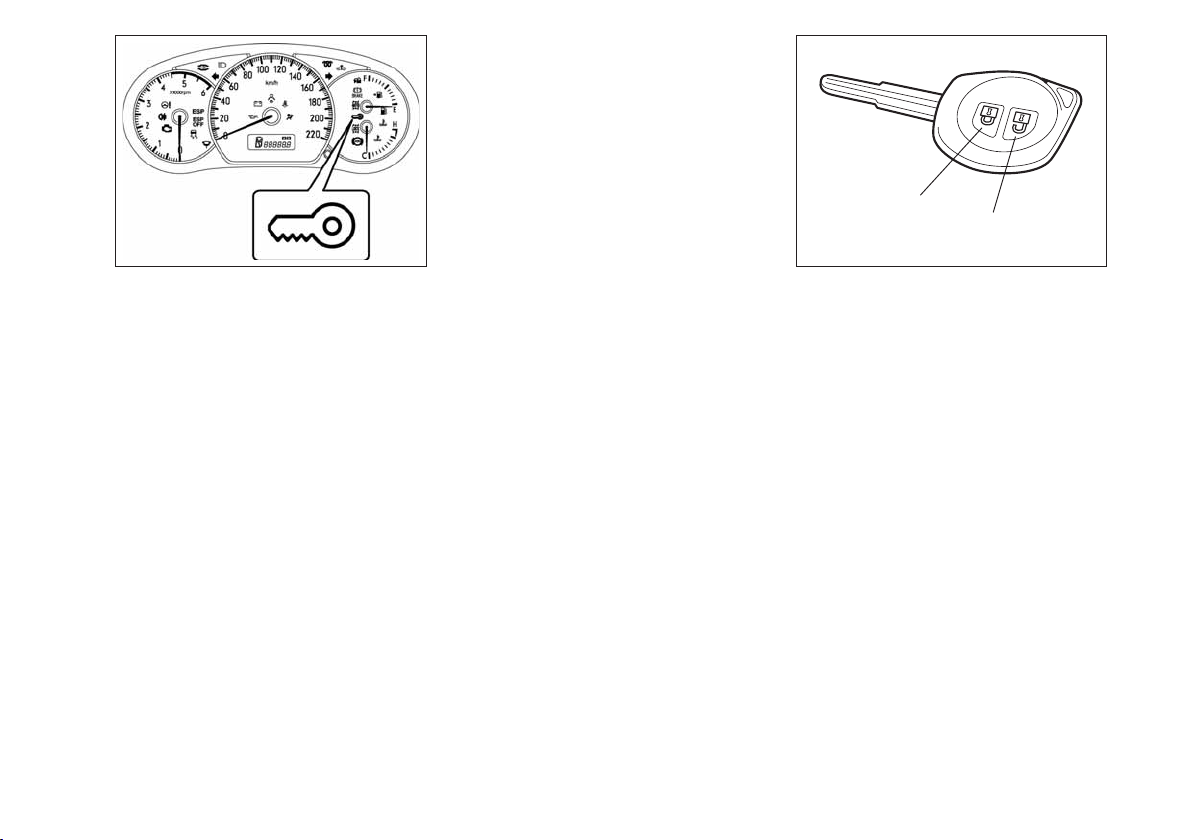
(1) (2)
62J127
If the immobilizer system light (1) for gasoline engine or service vehicle soon (SVS)
light (2) for diesel engine blinks when the
ignition switch is in the “ON” position, the
engine will not start.
NOTE
If this light blinks, turn the ignition switch
to the “LOCK” position, then turn it back
to the “ON” position. If the light still blinks
with the ignition switch turned to the
“ON” position, there may be something
wrong with your key or with the immobilizer system. Ask your Fiat dealer to inspect the system.
NOTE
❒
If you lose your Immobilizer ignition
key, see your Fiat Dealership as soon
as possible to have the lost one deactivated, then have the new key made by
them.
❒
If you own other vehicles with immobilizer keys, keep those keys away from
the ignition switch when using your Fiat, or the engine may not be started because they may interfere with your Fiat’s immobilizer system.
❒
In case of attaching any metal objects
to the immobilizer key, it may not start
the engine.
IMPORTANT The immobilizer key is a
sensitive electronic instrument. To avoid
damaging the immobilizer key:
❒
Do not expose it to impacts, moisture
or high temperature such as on the
dashboard under direct sunlight.
❒
Keep the immobilizer key away from
magnetic objects.
IMPORTANT The electronic components
inside the key may be damaged if the key
is submitted to sharp knocks.
This immobilizer system, model 5WK49181
and 5WK49182 for gasoline engine or
model 5WK49183 and 5WK49184 for
diesel engine are in compliance with the
essential requirements and other provisions of the Directive 1999/5/EC.
Ignition Key Reminder
(if equipped)
A buzzer sounds intermittently to remind
you to remove the ignition key if it is in
the ignition switch when the driver’s door
is opened.
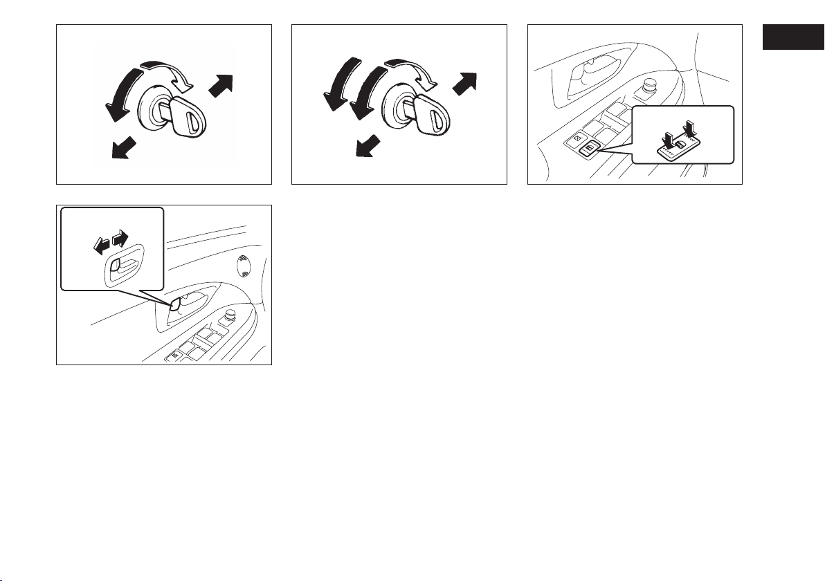
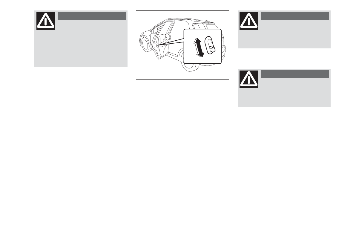
DOOR LOCKS
SIDE DOOR LOCKS
To lock a front door from outside the vehicle:
❒
Insert the key and turn the top of the
key toward the rear of the vehicle, or
❒
Turn the lock knob forward and hold
the door handle up as you close the
door.
To unlock a front door from outside the
vehicle, insert the key and turn the top of
the key toward the front of the vehicle.
To lock a rear door from outside the vehicle, turn the lock knob forward and
close the door.
To lock a door from inside the vehicle,
turn the lock knob forward. Turn the lock
knob rearward to unlock the door.
NOTE Be sure to hold the door handle
up when you close a locked front door, or
the door will not remain locked.
12
Page 14
UNLOCK
LOCK
Rear
UNLOCK
LOCK
Rear
LOCK
UNLOCK
Front
UNLOCK
LOCK
60B008
79J021
Front
54G294
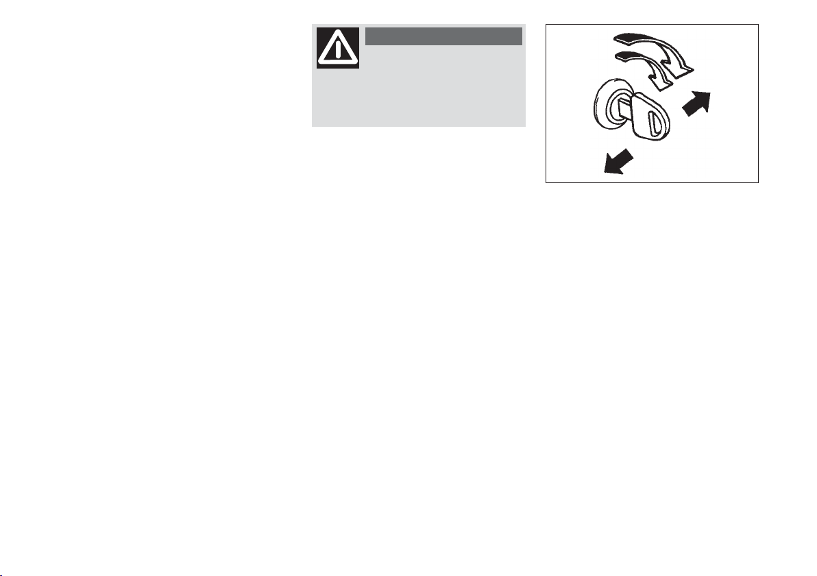
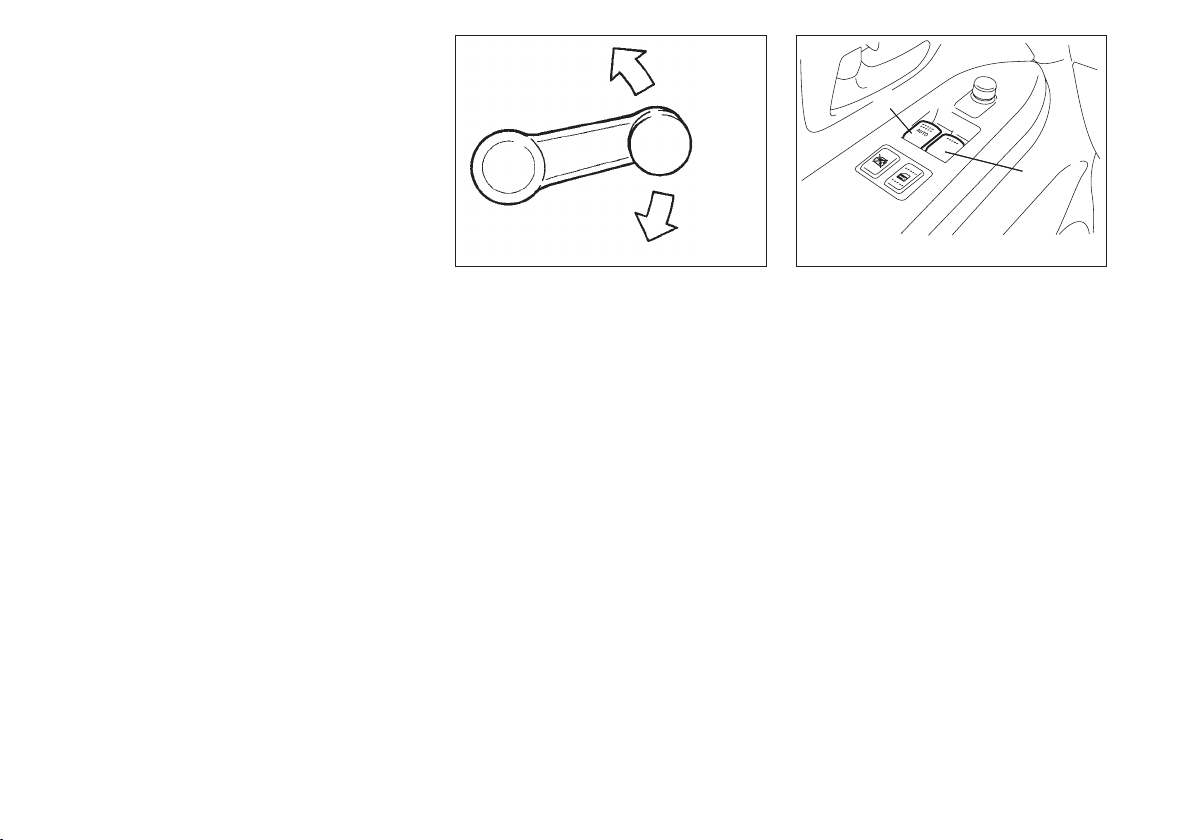
CENTRAL DOOR LOCKING
SYSTEM (if equipped)
You can lock and unlock all doors (including the rear door) simultaneously by
using the key in the driver’s door lock.
To lock all doors simultaneously, insert
the key in the driver’s door lock and turn
the top of the key toward the rear of the
vehicle once.
To unlock all doors simultaneously, insert
the key in the driver’s door lock and turn
the top of the key toward the front of the
vehicle twice.
To unlock the driver’s door only, insert
the key in that door lock and turn the top
of the key toward the front of the vehicle once.
79J022
You can also lock or unlock all doors by
depressing the front or rear of the switch,
respectively.
NOTE
❒
If your vehicle is equipped with the keyless entry system, you can also lock or
unlock all doors by operating the transmitter. Refer to “Keyless Entry System”
in this section.
❒
If your vehicle is equipped with the keyless start system, you can also lock or
unlock all doors by pushing the request
switch on the door handle. Refer to
“Keyless Start System” in this section.
13
Page 15
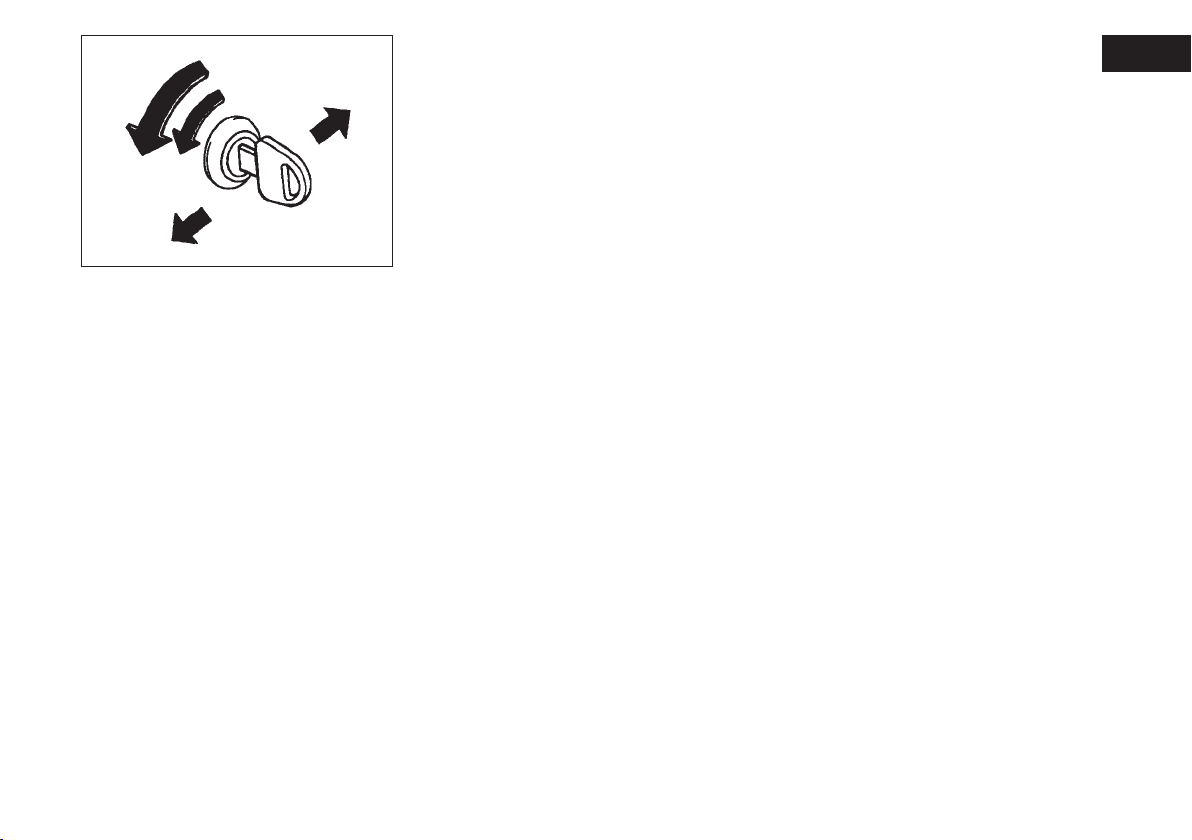
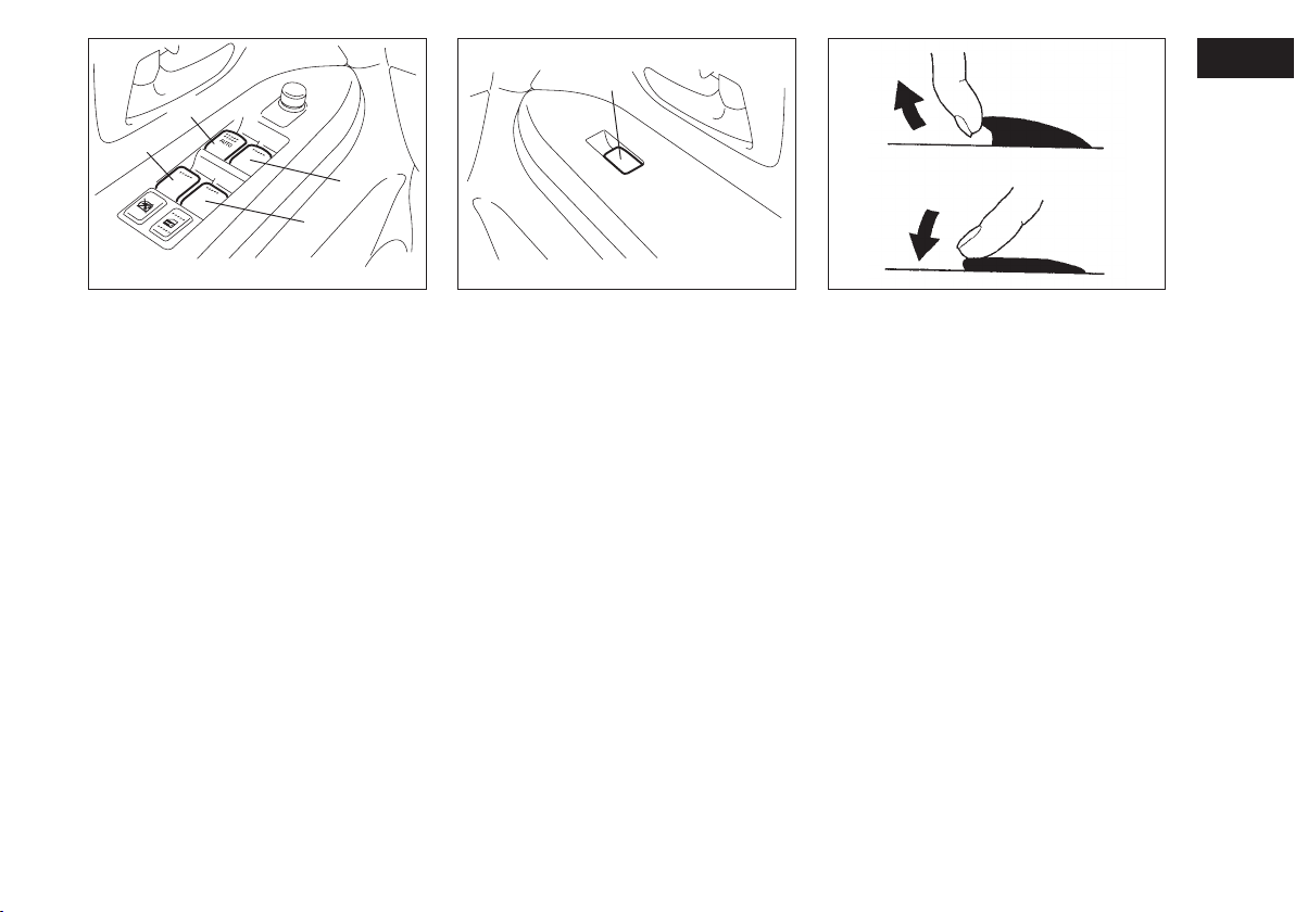
DEAD LOCK SYSTEM
(if equipped)
This system is designed to help prevent
tamper-unlocking of the door locks.
You can activate this system by turning the
key in the driver’s door lock.
NOTE
❒
If your vehicle is equipped with the keyless entry system, you can activate the
dead lock system by operating the
transmitter. Refer to “Keyless Entry
System” in this section.
❒
If your vehicle is equipped with the keyless start system, you can activate the
dead lock system by pushing the request switch on the door handle. Refer
to “Keyless Start System” in this section.
WARNING
Do not activate the dead
lock system if there are occupants in the vehicle. They will be
locked in the vehicle and cannot unlock the doors from inside.
NOTE
❒
The dead lock system will not operate
if one or more door (s) is (are) not
closed and latched completely. Make
sure all doors are completely closed
and latched when activating the dead
lock system.
❒
The dead lock system is released automatically allowing all the side doors
to be unlocked when the ignition switch
is turned to the “ON” position.
2 times
Rear
Front
83E107
To activate this system:
Insert the key in the driver’s door lock and
turn the top of the key toward the rear of
the vehicle twice within 3 seconds.
You can not use the lock knobs to unlock
the side doors when this system is activated.
14
Page 16
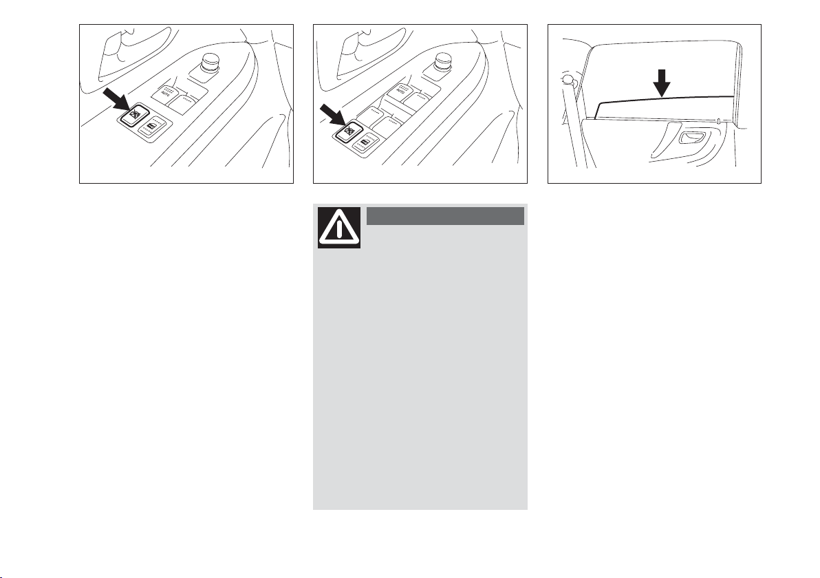
Rear
Front
83E105
To release this system:
To unlock all the side doors, insert the key
in the driver’s door lock and turn the top
of the key toward the front of the vehicle twice.
To unlock only the driver’s door, insert
the key in that door lock and turn the top
of the key toward the front of the vehicle once.
KEYLESS START SYSTEM
(if equipped)
The keyless start system enables the following operations:
❒
You can lock or unlock the doors by
pushing the request switch on the door
handle. For details, refer to the explanation in this section.
❒
You can start the engine without using
an ignition key. For details, refer to “Ignition Switch” in the “STEERING COLUMN CONTROLS” section and
“Starting the Engine” in the “OPERATING YOUR VEHICLE” section.
❒
You can lock or unlock the doors by
operating the LOCK/ UNLOCK buttons on the remote controller. Refer
to “Keyless Entry System” in the “BEFORE DRIVING” section.
NOTE The keyless start system may not
function correctly depending on the environment or operating conditions as follows:
❒
When there are strong signals coming
from a television, power station or a
cellular phone with you.
❒
When the remote controller is in contact with or covered by a metal object.
❒
When the radio wave type remote keyless entry is used nearby.
❒
When the remote controller is placed
near an electric appliance such as personal computer.
The Keyless Start System, controller model S62J1 and key model TS001 are in compliance with the essential requirements
and other provisions of Directive
1999/5/EC.
NOTE
❒
Make sure the ignition key is stowed
in the remote controller. If the remote
controller becomes unreliable, you can
not lock or unlock the doors and start
the engine.
❒
Be sure that the driver always carries
the remote controller.
❒
If you lose your remote controller, see
your Fiat Dealership as soon as possible to have the lost one deactivated.
❒
You can use up to four remote controllers and ignition keys for your vehicle. Ask your Fiat Dealership for details.
❒
The battery life of the remote controller is about two years, but it can
very depending on usage conditions.
15
Page 17
62J004
The turn signal lights will flash once when
the doors are locked and then the turn
signal lights will flash once again when the
doors are locked with the dead lock system.
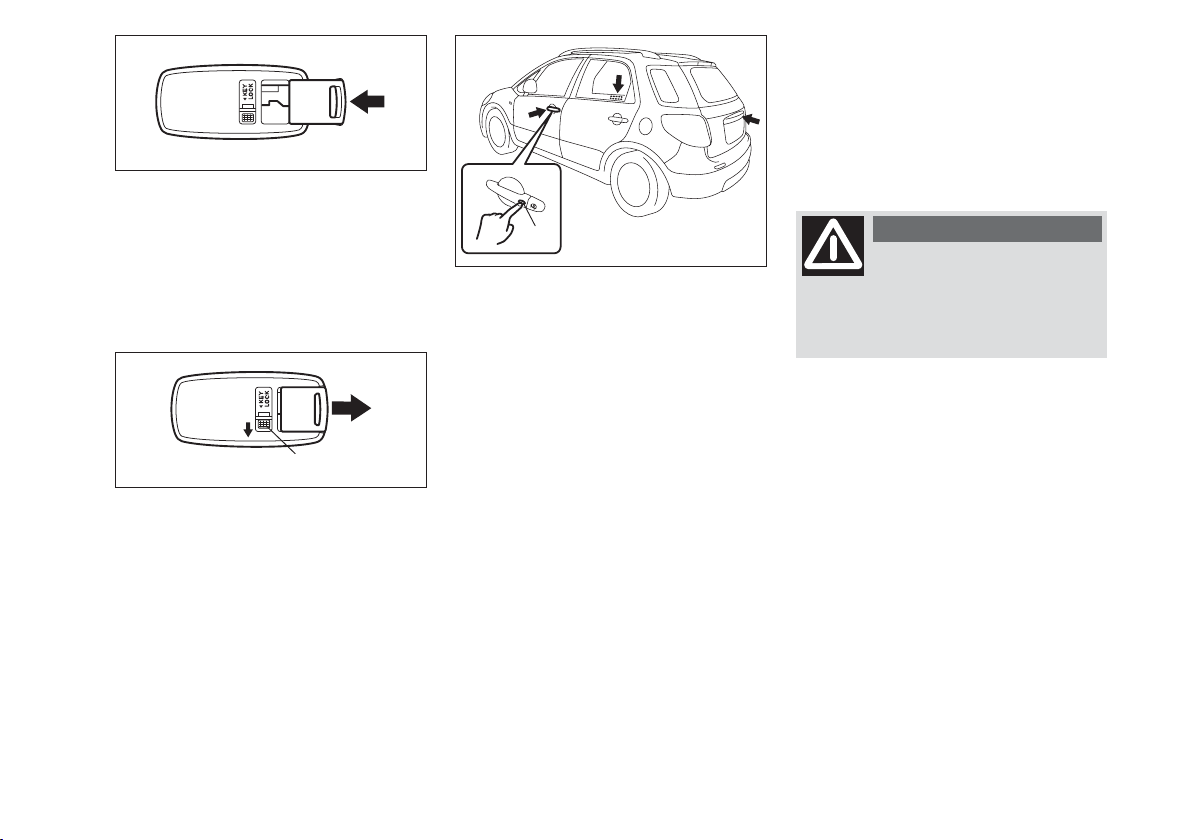
To stow the ignition key in the remote
controller, push the key in the remote
controller until the click is heard.
(A)
62J005
To remove the key from the remote controller, push the button (A) in the direction of the arrow and pull the key out
from the remote controller.
(1)
79J023
Keyless unlocking /
locking operation
When the remote controller is within the
access range, you can lock or unlock the
doors by pushing the request switch (1)
on the door handle of the driver’s door,
front passenger’s door or rear door. If you
want to prevent tamper- unlocking of the
door locks, you can activate the dead lock
system.
To lock or dead lock all doors when all
doors are unlocked:
❒
To lock all doors, push the request
switch on one of the door handles
once.
❒
To lock all doors with the dead lock
system, push the request switch on one
of the door handles twice within about
3 seconds.
WARNING
Do not activate the dead
lock system if there are occupants in the vehicle. They will be
locked in the vehicle and cannot unlock the doors from inside.
To unlock a door or all doors:
❒
To unlock the door only, push the request switch on the door handle once.
❒
To unlock other doors, push the request switch on the door handle once
again.
16
Page 18

When the door (s) is (are) unlocked:
❒
the turn signal lights will flash twice, and
❒
the interior light will turn on for about
15 seconds and then fade out with the
interior light switch in the middle position. If you push the ignition switch
during that time, the light will start to
fade out immediately.
Be sure the doors are locked after you operate the request switch to lock.
NOTE
❒
The door locks can not be operated by
the request switch under the following conditions:
– if any door is open or incompletely
closed;
– if the ignition switch is in a position
other than LOCK;
– if the ignition key is inserted in the ig-
nition switch.
❒
If no doors are opened within about 30
seconds after unlocking by pushing the
request switch, the doors will be locked
automatically again.
80 cm
80 cm
80 cm
64J007
When the remote controller is within approximately 80 cm from the front door
handle or rear door, you can lock or unlock the doors by pushing the request
switch.
NOTE
❒
The request switch operating range is
within approximately 80 cm of the door
handle or rear door handle. If the remote controller is outside this range, it
will not operate the request switch.
❒
If the battery of the remote controller
runs down or there are strong radio
waves or noise, the operating range
may be narrower or the remote controller may be inoperative.
❒
If you are too close to the door glass,
the remote controller may not operate.
❒
If a spare remote controller is in the vehicle, the request switches may not operate normally.
❒
The remote controller will only operate a request switch if it is within the
switch’s operating range. For example,
if the remote controller is within the
operating range of the driver’s door request switch, the driver’s door switch
can be operated but the front passenger’s door switch or rear door switch
can not be operated.
IMPORTANT The remote controller is
a sensitive electronic instrument. To avoid
damaging the remote controller:
❒
Do not expose it to impacts, moisture
or high temperature such as on the
dashboard under direct sunlight.
❒
Keep the remote controller away from
magnetic objects such as a television.
17
Page 19
(1)
(2)
79J186
Reminder function
If the remote controller is not in the vehicle under the following condition, a buzzer
sounds intermittently for about 2 seconds
and the keyless start system indicator light
on the instrument cluster blinks in red:
❒
When the vehicle speed is over 10 km/h.
❒
When the door (s) has (have) opened
and later all doors are closed with the
ignition switch in a position other than
LOCK.
The red indicator light will turn off within
several seconds after the remote controller
is returned in the vehicle except in the rear
luggage area.
If the remote controller is left in the vehicle and you lock the door in the following manner, the driver’s door or the front
passenger’s door will be automatically unlocked.
❒
You open the driver’s door and lock
the door by turning the lock knob forward or pushing the power door locking switch, the driver’s door will be automatically unlocked.
❒
You open the door (s) except the driver’s door and lock the front passenger’s door by turning the lock knob forward or pushing the power door locking switch, the front passenger’s door
will be automatically unlocked.
NOTE
❒
The reminder will not operate when
the remote controller is on the instrument panel, in the glove box, in the
door pocket, in the sun visor or on the
floor etc.
❒
Be sure that the driver always carries
the remote controller.
❒
Do not leave the remote controller in
the vehicle when departing from the vehicle.
Type 1
81A184
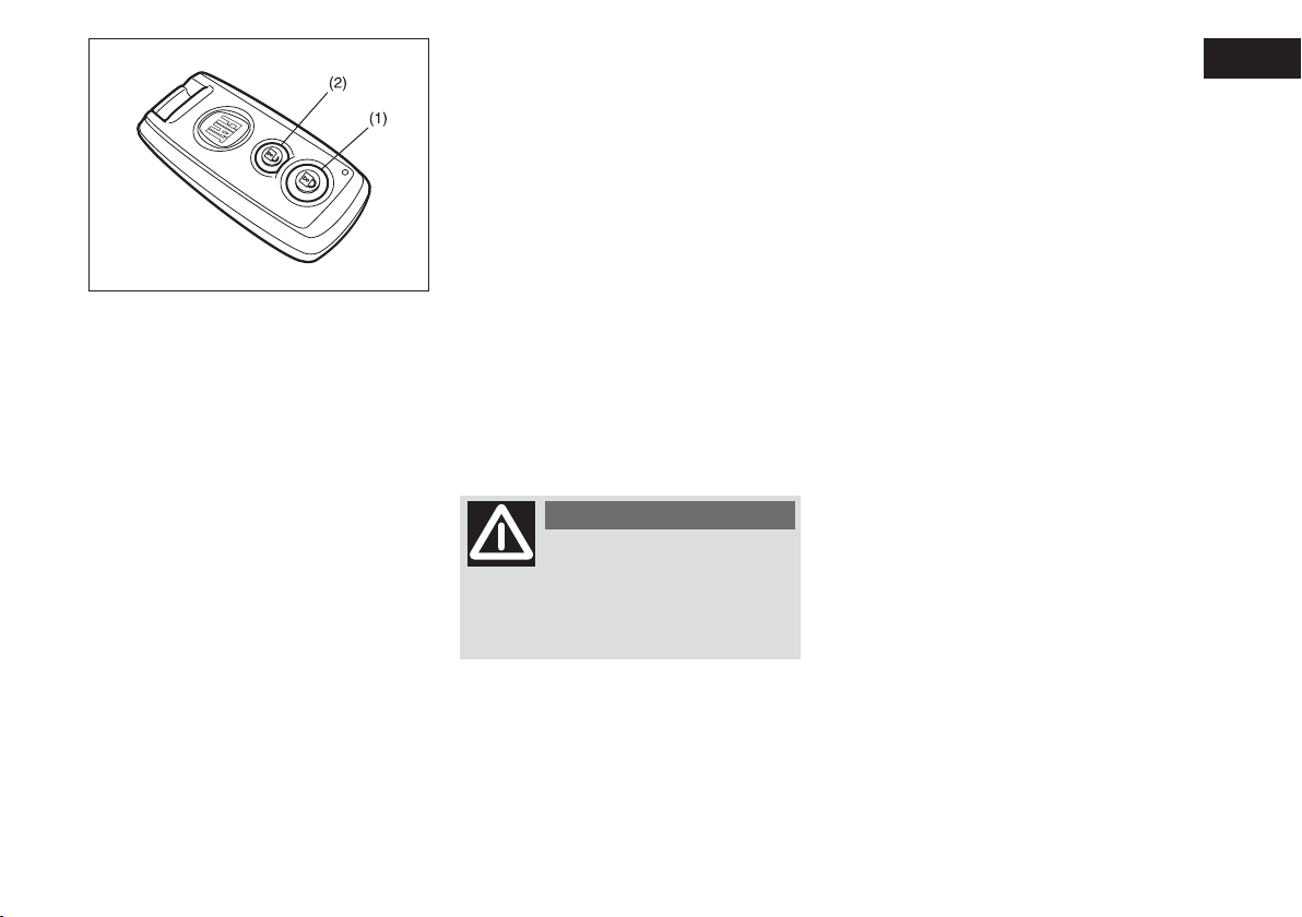
KEYLESS ENTRY SYSTEM
(if equipped)
(1) “LOCK” button
(2) “UNLOCK” button
There are two ways to lock or unlock all
doors simultaneously by operating the
transmitter/ remote controller near the
vehicle.
18
Page 20
Type 2
Central door locking system
❒
To lock all doors, push the “LOCK”
button (1) once.
❒
To unlock only the driver’s door, push
the “UNLOCK” button (2) once.
❒
To unlock other doors, push the “UNLOCK” button (2) once again.
189001
Central door locking system with
the dead lock system (if equipped)
If you want to prevent tamper- unlocking
of the door locks, use this method. When
the dead lock system is activated, operating the lock knobs will not unlock the
side doors.
To activate this system:
To lock all doors, push the “LOCK” but-
ton (1) twice within 3 seconds.
To release this system:
❒
To unlock only the driver’s door, push
the “UNLOCK” button (2) once.
❒
To unlock other doors, push the “UNLOCK” button (2) once again.
WARNING
Do not activate the dead
lock system if there are occupants in the vehicle. They will be
locked in the vehicle and cannot unlock the doors from inside.
The turn signal lights will flash once when
the doors are locked and then the turn
signal lights will flash once again when the
doors are locked with the dead lock system.
When the door (s) is (are) unlocked:
❒
The turn signal lights will flash twice,
and
❒
the interior light will turn on for about
15 seconds and then fade out with the
interior light switch in the middle position. If you insert the key into the ignition switch during that time, the light
will start to fade out immediately.
Be sure the doors are locked after you operate the “LOCK” button (1).
If no door is opened within about 30 seconds after the “UNLOCK” button (2) is
operated, the doors will automatically lock
again.
19
Page 21
(1)
(2)
NOTE
❒
The maximum operating distance is
about 5 meter (16 ft.), but this can vary
depending on the surroundings, especially near other transmitting devices
such as radio towers or CB (Citizen’s
Band) radios.
❒
The door locks can not be operated
with the transmitter/ remote controller:
– if the ignition switch is in a position
other than “LOCK” or the ignition
key is inserted in the ignition switch,
or
– if any door is open or incompletely
closed.
❒
If you lose your transmitter/ remote
controller, ask your Fiat Dealership as
soon as possible for a replacement and
to have the lost one deactivated.
Type 1
The Keyless Entry System, Transmitter
model TS002 and Receiver model R62J1
or R51K0 are in compliance with the essential requirements and other provisions
of Directive 1999/5/EC.
Type 2
The Keyless Start System, controller model S62J1 and key model TS001 are in compliance with the essential requirements
and other provisions of Directive
1999/5/EC.
IMPORTANT The transmitter/remote
controller is a sensitive electronic instrument. To avoid damaging the transmitter/remote controller:
❒
Do not expose it to impacts, moisture
or high temperature such as on the
dashboard under direct sunlight.
❒
Keep the transmitter/remote controller away from magnetic objects
such as a television.
81A185
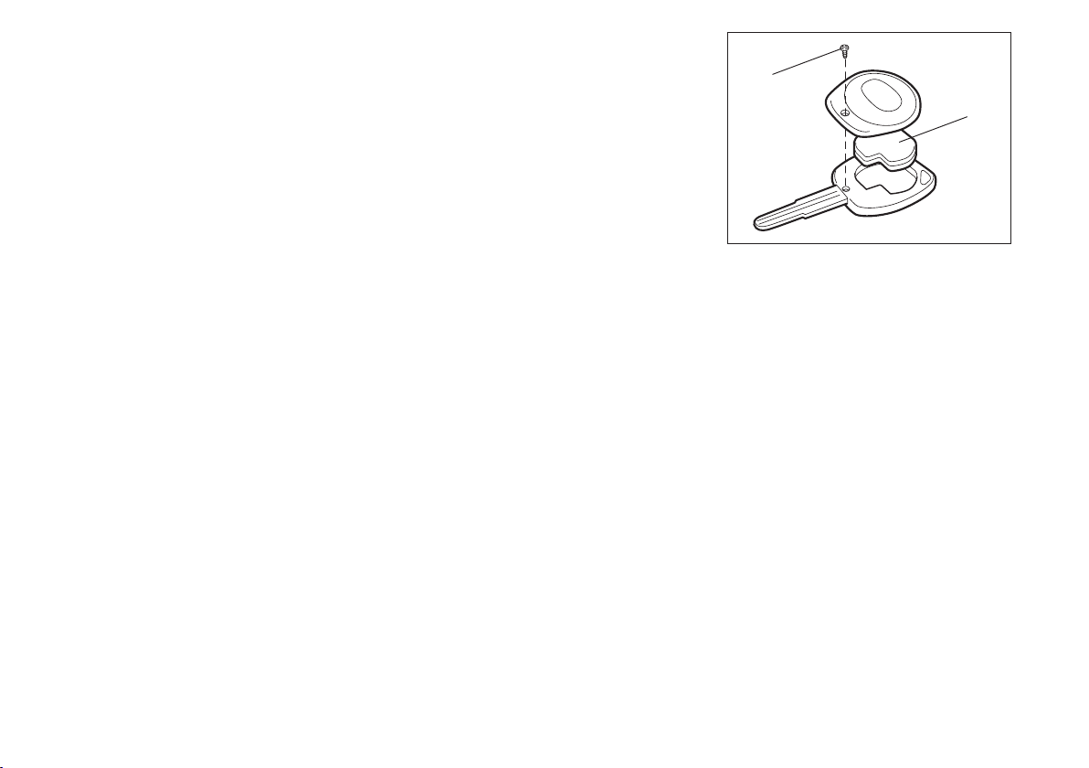
Replacement of the battery
If the transmitter/ remote controller becomes unreliable, replace the battery.
To replace the battery for the
transmitter of the keyless entry
❒
Remove the screw (1), and open the
transmitter cover.
❒
Remove the transmitter (2).
20
Page 22
(2)
(3)
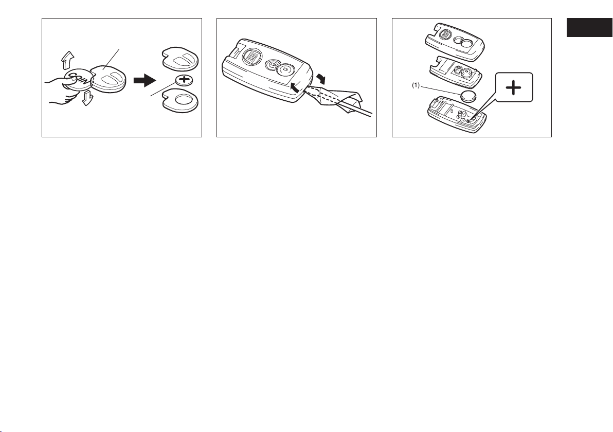
❒
Put the edge of a coin or a flat blade
screw driver in the slot of the transmitter (2) and pry it open.
❒
Replace the battery (3) (Lithium disctype CR1620 or equivalent) so its +
terminal faces the “+” mark of the
transmitter.
❒
Close the transmitter and install it into the transmitter holder.
❒
Close the transmitter cover, install and
tighten the screw (1).
❒
Make sure the door locks can be operated with the transmitter.
❒
Dispose of the used battery properly
according to applicable rules or regulations. Do not dispose of lithium batteries with ordinary household trash.
81A186
189002 189003
To replace the battery for the
remote controller of the keyless
start system
❒
Insert a flat blade screw driver covered
with a soft cloth in the slit of the remote controller and pry it open.
❒
Replace the battery (1) (Lithium disc
type CR2032 or equivalent) so its +
terminal faces the bottom of the case
as shown in the illustration.
❒
Close the remote controller firmly.
❒
Make sure the door locks can be operated with the remote controller.
❒
Dispose of the used battery properly
according to applicable rules or regulations. Do not dispose of lithium batteries with ordinary household trash.
21
Page 23
WARNING
Swallowing a lithium battery
may cause serious internal
injury. Do not allow anyone to swallow a lithium battery. Keep lithium
batteries away from children and
pets. If swallowed, contact physician
immediately.
IMPORTANT Used batteries are harmful to the environment. They should be
disposed of as specified by law in the special containers provided, or take them to
a Fiat Dealership, which will deal with their
disposal.
IMPORTANT The transmitter/ remote
controller is a sensitive electronic instrument. To avoid damaging it, do not expose
it to dust or moisture or tamper with internal parts.
(2)
(1)
79J025
Child-Proof Locks (rear side door)
As illustrated, a child-proof lock is provided for both rear doors. When the lock
lever is in position (1), the child-proof lock
is locked, and when in position (2), the
childproof lock is unlocked. When the
childproof lock is in the locked position,
the rear door cannot be opened from the
inside even if the inside door lock is unlocked but can be opened from the outside.
WARNING
Be sure to place the child-
proof lock in the locked position whenever children are seated in
the rear.
WARNING
After engaging the child lock
on both rear doors, check for
proper engagement by trying to open
a rear door with the internal handle.
22
Page 24

(1)
WARNING
Always make sure that the
rear door is closed and
latched securely. Completely closing
the rear door helps prevent occupants
from being thrown from the vehicle in
the event of an accident. Completely
closing it also helps keep exhaust gases from entering the vehicle.
(2)
79J026
Rear door
1) Rear door unlatch switch
You can lock and unlock the rear door by
using the key in the driver’s door lock.
To open the rear door, push and hold the
rear door unlatch switch (1) and lift the
rear door.
NOTE When the rear door is closed incompletely, follow the procedure below:
❒
Push the rear door unlatch switch (1)
and open the rear door a little.
❒
After a few seconds, close the rear
door.
❒
Make sure that the rear door is closed
completely.
If you can not unlatch the rear door by
pushing the unlatch switch (1) due to a discharged battery or malfunction, follow the
procedures below to unlatch the rear
door from inside the vehicle.
❒
Fold the rear seat forward for easier access. Refer to “Folding Rear Seats” section for details on how to fold the rear
seat forward.
79J099
❒
Push open the rear door from inside by
pushing up on the emergency lever (2)
using a flat blade screw driver or the
jack handle. The rear door will be
latched again by closing the rear door
simply.
If the rear door can not be unlatched, have
the vehicle inspected by your Fiat Dealership.
WARNING
To avoid injury, do not use
your finger to push the
emergency lever.
Make sure there is not anyone near
the rear door when pushing open the
rear door from inside the vehicle.
23
Page 25
(1)
(2)
WINDOWS
MANUAL WINDOW CONTROL
(if equipped)
Raise or lower the door windows by turning the handle located on the door panel.
60G010
Driver’s side (type A)
79J027
ELECTRIC WINDOW
CONTROLS (if equipped)
The electric windows can only be operated when the ignition switch is in the
“ON” position.
24
Page 26
(4)
(1)
(3)
CLOSE
(2)
(5)
Driver’s side (type B)
79J028
Driver’s side
The driver’s door has a switch (1) to operate the driver’s window, and a switch
(2) to operate the front passenger’s window or there are switches (4), (5), to operate the rear left and right passenger windows, respectively.
79J029
Passenger’s door
The passenger’s door has a switch (3) to
operate the passenger’s window.
OPEN
81A009
To open a window, push the top part of
the switch and to close the window lift up
the top part of the switch.
The driver’s window has an “auto-down”
feature for added convenience (at toll
booths or drive-through restaurants, for
example). This means you can open the
window without holding the window
switch in the “Down” position. Press the
driver’s window switch completely down
and release it. To stop the window before
it reaches the bottom, pull the switch up
briefly.
25
Page 27
Lock switch (type A)
Lock switch (type B)
79J030 79J031
54G011
The driver’s door also has a lock switch
for the passenger’s window (s). When you
push in the lock switch, the passenger’s
window (s) can not be raised or lowered
by operating any of the switches (2), (3),
(4) or (5). To restore normal operation,
release the lock switch by pushing again.
26
WARNING
You should always lock the
passenger’s window operation when there are children in the vehicle. Children can be seriously injured if they get part of their body
caught by the window during operation.
To avoid injuring an occupant by window entrapment, be sure no part of
the occupant’s body such as hands or
head is in the path of the electric windows when closing them.
Always remove the ignition key when
leaving the vehicle even if a short
time. Also do not leave children alone
in a parked vehicle. Unattended children could use the electric window
switches and get trapped by the window.
NOTE The rear side door windows are
not designed to open fully. They can be
opened about 2/3 of the way down.
Page 28
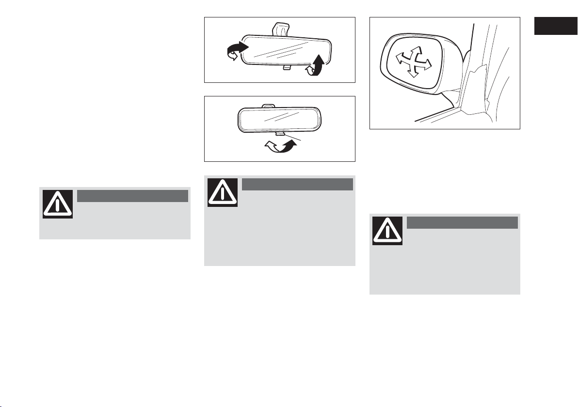
MIRRORS
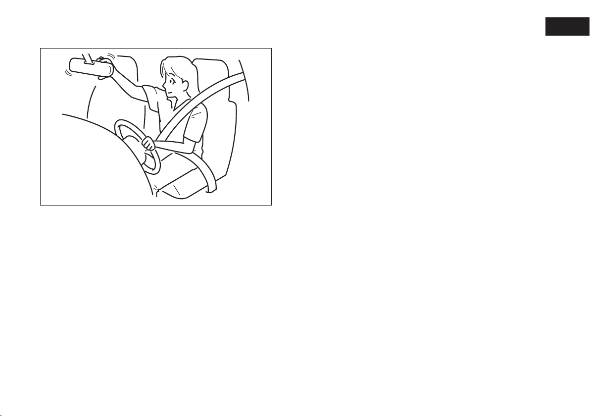
INSIDE REARVIEW MIRROR
You can adjust the inside rearview mirror
by hand so as to see the rear of your vehicle in the mirror. To adjust the mirror,
set the selector tab (1) to the day position, then move the mirror up, down or
sideways by hand to obtain the best view.
When driving at night, you can move the
selector tab to the night position to reduce glare from the headlights of vehicles
behind you.
WARNING
Always adjust the mirror
with the selector set to the
day position.
79J032
Day driving
(1)
Night driving
65D409
WARNING
Only use the night position
if it is necessary to reduce
glare from the headlights of vehicles
behind you. Be aware that in this position you may not be able to see
some objects that could be seen in the
day position.
79J033
OUTSIDE REARVIEW MIRRORS
Adjust the outside rearview mirrors so
you can just see the side of your vehicle in
the mirrors.
WARNING
Be careful when judging the
size or distance of a vehicle
or other object seen in the side convex mirror. Be aware that objects
look smaller and appear farther away
than when seen in a flat mirror.
27
Page 29

SEAT ADJUSTMENT
(2)
(4)
(3)
(1)
(1)
(3)(2)
(4)
WARNING
Only make adjustments when
the vehicle is stationary.
WARNING
To avoid excessive seat belt
slack, which reduces the effectiveness of the seat belts as a safety device, make sure that the seats
are adjusted before the seat belts are
fastened.
28
ELECTRIC MIRRORS (if equipped)
The switch to control the electric mirrors
is located on the driver’s door panel. You
can adjust the mirrors when the ignition
switch is in the “ACC” or “ON” position.
To adjust the mirrors:
❒
Move the selector switch to the left or
right to select the mirror you wish to
adjust.
❒
Press the outer part of the switch that
corresponds to the direction in which
you wish to move the mirror.
❒
Return the selector switch to the center position to help prevent unintended adjustment.
79J034
WARNING
Check that the seat is firmly
locked in the runners by trying to move it back and forth. Failure
to lock the seat in place could result
in the seat moving suddenly and the
driver losing control of the vehicle.
Page 30
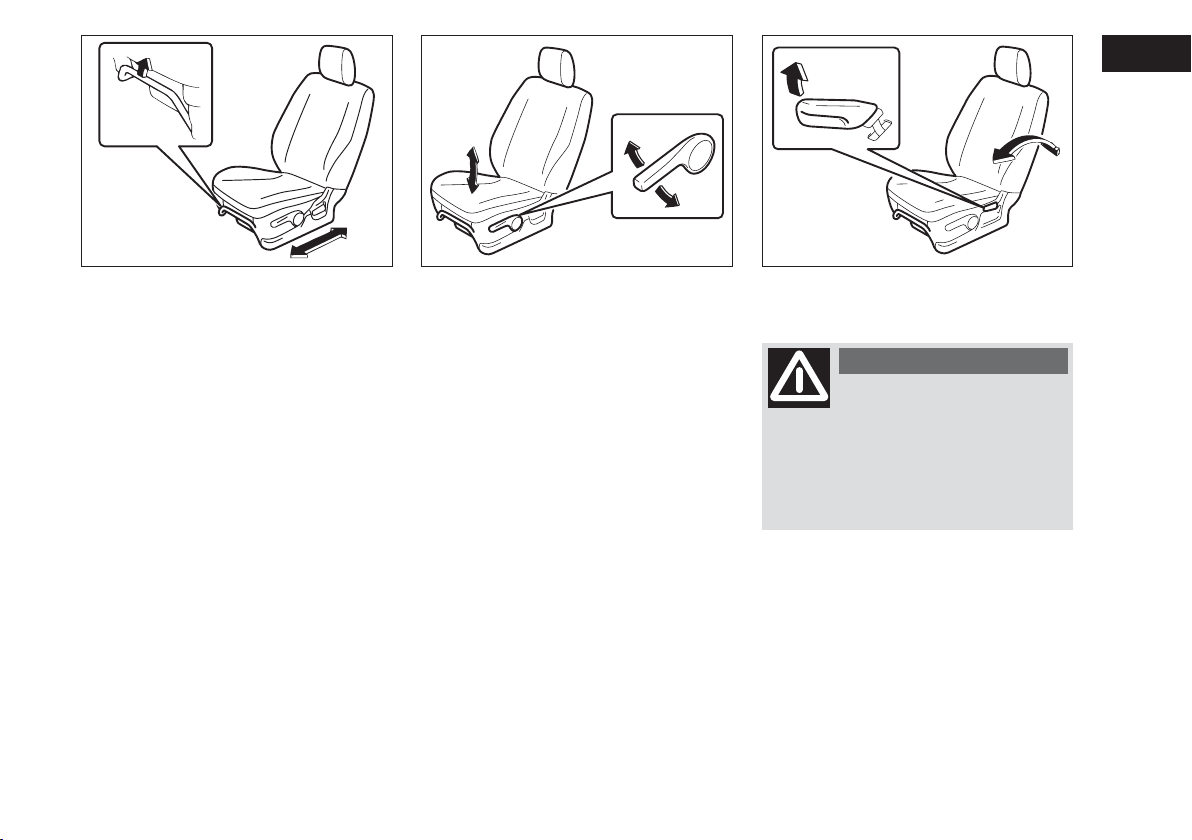
79J114 79J055 79J056
The adjustment lever for each front seat
is located under the front of the seat. To
adjust the seat position, pull up on the adjustment lever and slide the seat forward
or rearward.
After adjustment, try to move the seat forward and rearward to ensure that it is securely latched.
If the driver’s seat is equipped with a seat
height adjuster lever on the outboard side
of the seat, raise or lower the seat by
pulling up or down the adjuster lever.
ADJUSTING SEATBACKSADJUSTING SEAT POSITION
WARNING
All seatbacks should always
be in an upright position
when driving, or seat belt effectiveness may be reduced. Seat belts are
designed to offer maximum protection when seatbacks are in the upright position.
To adjust the seatback angle of front seats,
pull up the lever on the outboard side of
the seat, move the seatback to the desired
position, and release the lever to lock the
seatback in place.
29
Page 31

ADJUSTABLE HEAD
RESTRAINTS
(if equipped)
Head restraints are designed to help reduce the risk of neck injuries in the case
of an accident. Adjust the head restraint
to the position which places the center
of the head restraint closest to the top of
your ears. If this is not possible for very
tall passengers, adjust the head restraint
as high as possible.
WARNING
Remember that the head re-
straints should be adjusted
to support the back of your head and
not your neck. Only in this position
do they exert their protective action.
Do not attempt to adjust the head restraint while driving.
75F123 63J015
NOTE It may be necessary to recline the
seatback to provide enough overhead
clearance to remove the head restraint.
Front
To raise the front head restraint, pull upward on the restraint until it clicks. To
lower the restraint, push down on the restraint while holding in the lock lever. If a
head restraint must be removed (for
cleaning, replacement, etc.), push in the
lock lever and pull the head restraint all
the way out.
30
Page 32

SEAT BELTS AND CHILD
RESTRAINT SYSTEMS
WARNING
Wear Your Seat Belts at All
Times.
63J135
Rear
To raise the rear head restraint, pull upward on the restraint until it clicks. To
lower the restraint, push down on the restraint while holding in the lock lever. If a
head restraint must be removed (for
cleaning, replacement, etc.), push in the
lock lever and pull the head restraint all
the way out.
When installing a child restraint system,
raise the head restraint to the most upper
position.
WARNING
An air bag supplements, or
adds to, the frontal crash
protection offered by seat belts. The
driver and all passengers must be
properly restrained by wearing seat
belts at all times, whether or not an
air bag is mounted at their seating position, to minimize the risk of severe
injury or death in the event of a crash.
WARNING
Never allow persons to ride
in the cargo area of a vehicle. In the event of an accident, there
is a much greater risk of injury for
persons who are not riding in a seat
with their seat belt securely fastened.
Above the pelvis
Across the pelvis
65D231
65D360
65D201
31
Page 33

WARNING
Seat belts should always be
adjusted as follows:
– The lap portion of the belt should
be worn low across the pelvis, not
across the waist.
– The shoulder straps should be worn
on the outside shoulder only, and never under the arm.
– The shoulder straps should be away
from your face and neck, but not
falling off your shoulder.
– Seat belts should never be worn
with the straps twisted and should be
adjusted as tightly as is comfortable
to provide the protection for which
they have been designed. A slack belt
will provide less protection than one
which is snug.
– Make sure that each seat belt buckle is inserted into the proper buckle
catch. It is possible to cross the buckles in the rear seat.
as low as possible
across the hips
65D199
WARNING
Pregnant women should use
seat belts, although specific
recommendations about driving
should be made by the woman’s medical advisor. Remember that the lap
portion of the belt should be worn as
low as possible across the hips, as
shown in the diagram.
Do not wear your seat belt over hard
or breakable objects in your pockets
or on your clothing. If an accident occurs, objects such as glasses, pens, etc.
under the seat belt can cause injury.
WARNING
Never use the same seat belt
on more than one occupant
and never attach a seat belt over an
infant or child being held on an occupant’s lap. Such seat belt use could
cause serious injury in the event of an
accident.
Periodically inspect seat belt assemblies for excessive wear and damage.
Seat belts should be replaced if webbing becomes frayed, contaminated,
or damaged in any way. It is essential
to replace the entire seat belt assembly after it has been worn in a severe impact, even if damage to the
assembly is not obvious.
Children age 12 and under should ride
properly restrained in the rear seat.
Infants and small children should never be transported unless they are
properly restrained. Restraint systems
for infants and small children can be
purchased locally and should be used.
Make sure that the system you purchase meets applicable safety standards. Read and follow all the directions provided by the manufacturer.
32
Page 34

WARNING
Avoid contamination of seat
belt webbing by polishes,
oils, chemicals, and particularly battery acid. Cleaning may safely be carried out using mild soap and water.
For children, if the shoulder belt irritates the neck or face, move the child
closer to the center of the vehicle.
All seatbacks should always be in an
upright position when driving, or seat
belt effectiveness may be reduced.
Seat belts are designed to offer maximum protection when seatbacks are
in the upright position.
WARNING
Under no circumstances
should the components of
the seat belts and pretensioners be
tampered with or removed. Any operation should be carried out by qualified and authorised personnel. Always contact a Fiat Dealership.
LAP-SHOULDER BELT
Emergency Locking Retractor
(ELR)
The seat belt has an emergency locking
retractor (ELR), which is designed to lock
the seat belt only during a sudden stop
or impact. It also may lock if you pull the
belt across your body very quickly. If this
happens, let the belt go back to unlock it,
then pull the belt across your body more
slowly.
Sit up straight and
fully back
Low on hips
Low on hips
60A038
60A040
33
Page 35

Safety reminder
To reduce the risk of sliding under the belt
during a collision, position the lap portion
of the belt across your lap as low on your
hips as possible and adjust it to a snug fit
by pulling the shoulder portion of the belt
upward through the latch plate. The length
of the diagonal shoulder strap adjusts itself to allow freedom of movement.
60A036 79J057
34
To fasten the seat belt, sit up straight and
well back in the seat, pull the latch plate
attached to the seat belt across your body
and press it into the buckle until you hear
a “click”.
NOTE The word “CENTER” is molded into the buckle for the rear center belt. The
buckles are designed so a latch plate can
not be inserted into the wrong buckle.
Page 36

60A039 79J187
To unfasten the belt, push the red
“PRESS” button on the buckle and allow
the belt to retract.
DRIVER’S SEAT BELT
REMINDER
When the driver doesn’t buckle his or her
seat belt, the driver’s seat belt reminder
light in the instrument cluster will come
on and a buzzer will sound as a reminder
to the driver to buckle his or her seat belt.
For more details, refer to the explanation
below.
If the driver’s seat belt remains unbuckled
when the ignition switch is turned to the
“ON” position, the reminder works as follows:
1) The driver’s seat belt reminder light will
come on.
2) After the vehicle’s speed has reached
about 15 km/ h, the driver’s seat belt
reminder light will blink and a buzzer
will sound for about 95 seconds.
3) After step 2) has finished, the reminder
light will remain on until the driver’s
seat belt is buckled.
If the driver has buckled his or her seat
belt and later unbuckles the seat belt, the
reminder system will be activated from
step 1) or step 2) according to the vehicle’s speed. When the vehicle’s speed is
below about 15 km/h, the reminder will
start from step 1). When the vehicle’s
speed is above about 15 km/h, the reminder will start from step 2).
The reminder will be automatically canceled when the driver’s seat belt is buckled or the ignition switch is turned off.
WARNING
It is absolutely essential that
the driver and passengers
wear their seat belts at all times. Persons who are not wearing seat belts
have a much greater risk of injury if
an accident occurs. Make a regular
habit of buckling your seat belt before
putting the key in the ignition.
35
Page 37

WARNING
Be sure that the shoulder
belt is positioned on the center of the outside shoulder. The belt
should be away from your face and
neck, but not falling off your shoulder. Misadjustment of the belt could
reduce the effectiveness of the safety belt in a crash.
SHOULDER ANCHOR HEIGHT
ADJUSTER (if equipped)
Adjust the shoulder anchor height so that
the shoulder belt rides on the center of
the outboard shoulder. To adjust the
shoulder anchor height, slide the anchor
up or down while pulling the lock knob
out. After adjustment, make sure that the
anchor is securely locked.
36
64J198
79J035
SEAT BELT HANGER
(if equipped)
When you move a seatback, make sure
the belt webbing is hooked in the seat belt
hangers so the seat belts are not caught
by the seatback, seat hinge, or seat latch.
This helps prevent damage to the belt system.
Page 38

65D209S
SEAT BELT INSPECTION
Periodically inspect the seat belts to make
sure they work properly and are not damaged. Check the webbing, buckles, latch
plates, retractors, anchorages, and guide
loops. Replace any seat belts which do not
work properly or are damaged.
WARNING
Be sure to inspect all seat
belt assemblies after any collision. Any seat belt assembly which
was in use during a collision (other
than a very minor one) should be replaced, even if damage to the assembly is not obvious. Any seat belt assembly which was not in use during
a collision should be replaced if it
does not function properly, it is damaged in any way or the seat belt pretensioners were activated (that is, if
the front air bags were activated).
WARNING
Under no circumstances
should the components of
the seat belts and pretensioners be
tampered with or removed. Any operation should be carried out by qualified and authorised personnel. Always contact a Fiat Dealership.
60G332S
CHILD RESTRAINT SYSTEMS
Fiat highly recommends that you use a
child restraint system to restrain infants
and small children. Many different types of
child restraint systems are available; make
sure that the restraint system you select
meets applicable safety standards.
All child restraint systems are designed to
be secured in vehicle seats by either seat
belts (lap belts or the lap portion of lapshoulder belts) or by special rigid lower
anchor bars built into the seat. Whenever possible, Fiat recommends that child restraint systems be installed on the rear
seat. According to accident statistics, children are safer when properly restrained
in rear seating positions than in front seating positions.
37
Page 39

Infant restraint - rear seat only
79J221
Booster seat
79J223
65D361
Child restraint
If you must use a front-facing child restraint in the front passenger’s seat, adjust
the passenger’s seat as far back as possible.
38
79J222
(For EU countries)
When purchasing a child restraint and install it to your FIAT, refer to the information about suitability for child restraints
shown in “Child Restraint System for EU
Countries” in this section.
The child restraint installation to this model is limited to the left position of the rear
seat except ISOFIX type child restraint of
the group 1; child weight 9 to 18kg.
NOTE Observe any statutory regulation
about child restraints.
WARNING
The figure is only an exam-
ple for mounting. Attain to
the instructions for fastening which
must be enclosed with the specific
child restraining system you are using.
WARNING
If your vehicle is equipped
with a front passenger air
bag, do not install a rear-facing child
restraint in the front passenger’s seat.
If the passenger’s air bag inflates, a
child in a rear-facing child restraint
could be killed or seriously injured.
The back of a rear-facing child restraint would be too close to the inflating air bag.
Page 40

65D362 65D363
WARNING
If you install a child restraint
system in the rear seat, slide
the front seat for enough forward so
that the child’s feet do not contact
the front seatback. This will help
avoid injury to the child in the event
of an accident.
WARNING
Children could be endan-
gered in a crash if their child
restraints are not properly secured in
the vehicle. When installing a child restraint system, be sure to follow the
instructions below. Be sure to secure
the child in the restraint system according to the manufacturer’s instructions.
WARNING
If your vehicle is equipped
with side air bags, do not install a child restraint in the front passenger’s seat. If the passenger’s side
air bag inflates, a child in a child restraint could be severely injured.
WARNING
In an accident or sudden
stop, the rear seat armrest (if
equipped) could fall forward. If there
is a child in a rear-facing child restraint in the rear center seating position, the falling armrest could injure
the child. Do not install a rear- facing
child restraint in the rear center seating position.
39
Page 41

CHILD RESTRAINT SYSTEM FOR EU COUNTRIES
CHILD RESTRAINT
The suitability of each passenger’s seat position for carriage of children and fitting of child restraint system is shown in the table below. Whenever you carry children under 12 years of age or smaller than 150 cm, properly use the child restraints which conform
to ECE-R Norm 44, the standard for child restraints, referring to the table.
Table of vehicle handbook information on conventional (fastening with seat belt) child restraint systems
installation suitability for various seating positions
Mass group Seating position (or other site)
Front Rear Rear Intermediate Intermediate
Passenger Outboard Center Outboard Center
group 0 up to 10 kg
group 0+ up to 13 kg
group 1 9 to 18 kg
group 2 15 to 25 kg
group 3 22 to 36 kg
Key of letters to be inserted in the above table:
U = suitable for “universal” category restraints approved for use in this mass group.
UF = suitable for forward-facing “universal” category restraints approved for use in this mass group.
L = suitable for particular child restraints given on attached list These restraints may be of the “specific vehicle”, “restricted” or
“semi-universal” categories.
B = built-in restraint approved for this mass group.
X = seat position not suitable for children in this mass group.
NA = not applicable.
* ISOFIX child restraint systems are available to both left and right position.
NOTE “universal” is the category in the ECE regulation-Norm 44.
X
X
X
X
X
U (only left)
U (only left)
U (only left) *
UF (only left)
UF (only left)
X
X
X
X
X
NA
NA
NA
NA
NA
40
NA
NA
NA
NA
NA
Page 42

Table of vehicle handbook information on ISOFIX child restraint systems installation suitability for various
ISOFIX positions
Vehicle ISOFIX positions
Mass group
Size
class
Fixture Front Rear Rear Intermediate Intermediate Other
Passanger Outboard Center Ourboard Center Sites
NA
NA
NA
NA
NA
NA
NA
NA
NA
NA
NA
NA
NA
NA
NA
NA
NA
carrycot
F
G
ISO/L1
ISO/L2
(1)
group 0 up to 10 kg
group 0+ up to 13 kg
E
E
D
C
ISO/R1
(1)
ISO/R1
ISO/R2
ISO/R3
(1)
group 1 9 to 18 kg
D
C
B1
A
ISO/R2
ISO/R3
B
ISO/F2
ISO/F2X
ISO/F3
(1)
group 2 15 to 25 kg
group 3 22 to 36 kg
(1) For the child restraint system which do not carry the ISO/XX size class identification (A to G), for the applicable mass group, the car manu-
facturer shall indicate the vehicle specific ISOFIX child restraint system(s) recommended for each position.
Key of letters to be inserted in the above table:
IUF = suitable for ISOFIX forward child restraint systems of universal category approved for use in this mass group Fiat recommends RÖMER
DUO plus, available at Lineaccessori Fiat..
IL = suitable for particular ISOFIX child restraint system are those of the “specific vehicle”, “restricted” or “semi-universal” categories.
X = ISOFIX position not suitable for ISOFIX child restraint systems in this mass group and/or this size class.
ND = not applicable.
NOTE “universal” is the category in the ECE regulation-Norm 44.
(1)
(1)
X
X
NA
X
NA
X
X
X
ND
X
X
IUF
IUF
IL
NA
NA
NA
NA
NA
NA
NA
NA
NA
NA
NA
NA
NA
NA
NA
NA
NA
NA
NA
NA
NA
NA
NA
NA
NA
NA
NA
NA
NA
NA
NA
NA
NA
NA
NA
NA
NA
NA
NA
NA
NA
NA
NA
NA
NA
NA
NA
NA
NA
NA
NA
NA
NA
NA
NA
NA
NA
NA
NA
NA
NA
NA
NA
NA
NA
NA
NA
NA
NA
NA
NA
41
Page 43

79J224
79J058
63J020
INSTALLATION WITH LAPSHOULDER SEAT BELTS
(available to the left position of the
rear seat)
IMPORTANT Before installing a child restraint system in the rear seat, raise the
head restraint to the most upper position.
ELR type belt
WARNING
Install your child restraint
system according to the instructions provided by the child restraint system manufacturer.
Make sure that the seat belt is securely
latched.
Try to move the child restraint system in
all directions, to make sure it is securely
installed.
42
INSTALLATION WITH ISOFIX
TYPE ANCHORAGES
(available to both left and right
position of the rear seat with the
ISOFIX type of the group 1; child
weight 9 to 18kg)
Your vehicle is equipped with the lower
anchorages in the rear seat outboard seating positions for securing a ISOFIX type of
child restraints with the connecting bars.
The lower anchorages are located where
the rear of the seat cushion meets the bottom of the seatback.
WARNING
Be sure to install the ISOFIX
type of child restraint(s) in
the only outboard seating positions,
not in the central position for rear
seat.
WARNING
Install the ISOFIX type child
restraint system according to
the instructions provided by the child
restraint system manufacturer. After
installing, try moving the child restraint system in all directions especially forward, to make sure the connecting bars are securely latched to
the anchorages.
If your vehicle is equipped with the top
strap anchorages, be sure to use the top
strap of the child restraint according to
the instructions provided by the child restraint system manufacture.
Page 44

78F114 54G183 54G184
Here is a general instruction:
❒
Pull upward on the rear head restraint
to the most upper position.
IMPORTANT Before installing a child restraint system in the rear seat, raise the
head restraint to the most upper position.
❒
If possible, fold the seatback rearward
for easier installation.
❒
Place the child restraint in the rear seat,
inserting the connecting bars to the anchorages between the seat cushion and
the seatback.
❒
Use your hands to carefully align the
connecting bar tips with the anchorages. Take care not to pinch your fingers.
❒
Push the child restraint toward the anchorages so that the connecting bar tips
are partially hooked to the anchorages.
Use your hands to confirm the position.
43
Page 45

54G185 62J026
❒
Hook the top strap to the anchor
bracket and tighten the top strap according to the instructions provided by
the child restraint system manufacturer. Be sure to attach the top strap to
the corresponding anchor located directly behind the child restraint. Do not
attach the top strap to the luggage restraint loops (if equipped).
44
❒
Grasp the front of the child restraint
and push the child restraint forcefully
to latch the connecting bars. Make sure
they are securely latched by trying to
move the child restraint system in all directions, especially forward.
❒
Return the seatback if folded.
❒
Attach the top strap referring to “Installation of Child Restraint with Top
Strap” section below (if equipped).
INSTALLATION OF CHILD
RESTRAINT WITH TOP STRAP
Some child restraint systems require the
use of a top strap. Top strap anchor brackets are located on the back of the rear
seatbacks. The number of the anchor
bracket provided in your vehicle depends
on the vehicle specification.
Install the child restraint system as follows:
❒
Remove the luggage compartment cover.
❒
Secure the child restraint on rear seat
using the procedure described above
for securing a restraint system that
does not require a top strap.
WARNING
Do not attach the child re-
straint top strap to the luggage restraint loops (if equipped). Incorrectly attached top strap will reduce
the intended effectiveness of the child
restraint system.
Page 46

Type 1
Type 2
❒
When routing the top strap, be sure to
pass the top strap as shown in the illustration. (Refer to “Adjustable Head
Restraints” section for details on how
to raise or lower the head restraint.).
❒
Make sure that cargo does not interfere with routing of the top strap.
86G032
and/or
Label
65D205
SEAT BELT PRETENSIONER
SYSTEM (if equipped)
WARNING
This section of the owner’s
manual describes your Fiat’s
SEAT BELT PRETENSIONER SYSTEM. Please read and follow ALL
these instructions carefully to minimize your risk of severe injury or
death.
To determine if your vehicle is equipped
with a seat belt pretensioner system at the
front seating positions, check the label on
the front seat belt at the bottom part. If
the letters “p” and/or “PRE” appear as illustrated, your vehicle is equipped with
the seat belt pretensioner system. You can
use the pretensioner seat belts in the same
manner as ordinary seat belts.
Read this section and the “Supplemental
Restraint System (air bags)” section to
learn more about the pretensioner system.
The seat belt pretensioner system works
with the SUPPLEMENTAL RESTRAINT
SYSTEM (Air Bags). The crash sensors and
the electronic controller of the air bag system also control the seat belt pretensioners. When the air bags are triggered,
the pretensioners are also triggered. For
precautions and general information including servicing the pretensioner system,
refer to the “Supplemental Restraint System (air bags)” section in addition to this
“Seat Belt Pretensioner System” section,
and follow all those precautions.
45
Page 47

The pretensioner is located in each front
seat belt retractor. The pretensioner tightens the seat belt so the belt fits the occupant’s body more snugly in the event of
a frontal crash. The retractors will remain
locked after the pretensioners are activated. Upon activation, some noise will occur and some smoke may be released.
These conditions are not harmful and do
not indicate a fire in the vehicle.
The driver and all passengers must be
properly restrained by wearing seat belts
at all times, whether or not a pretensioner is equipped at their seating position, to
minimize the risk of severe injury or death
in the event of a crash.
Sit fully back in the seat; sit up straight; do
not lean forward or sideways. Adjust the
belt so the lap portion of the belt is worn
low across the pelvis, not across the waist.
Please refer to the “Seat Adjustment” section and the instructions and precautions
about the seat belts in this “Seat Belts and
Child Restraint Systems” section for details on proper seat and seat belt adjustments.
Please note that the pretensioners along
with the air bags will activate only in severe frontal collisions. They are not designed to activate in rear impacts, side impacts, rollovers, or minor frontal collisions. The pretensioners can be activated only once. If the pretensioners are activated (that is, if the air bags are activated), have the pretensioner system serviced by an authorized Fiat Dealership as
soon as possible.
If the “AIR BAG” light on the instrument
cluster does not blink or come on briefly
when the ignition switch is turned to the
“ON” position, stays on for more than 10
seconds, or comes on while driving, the
pretensioner system or the air bag system
may not work properly. Have both systems inspected by an authorized Fiat Dealership as soon as possible.
WARNING
Service on or around the
pretensioner system components or wiring must be performed
only by an authorized Fiat Dealership
who is specially trained. Improper service could result in unintended activation of pretensioners or could render the pretensioner inoperative. Either of these two conditions may result in personal injury.
To prevent damage or unintended activation of the pretensioners, be sure the battery is disconnected and the ignition switch
has been in the “LOCK” position for at
least 90 seconds before performing any
electrical service work on your Fiat.
Do not touch pretensioner system components or wiring. The wires are wrapped
with yellow tape or yellow tubing, and the
couplers are yellow. When scrapping your
Fiat, ask your Fiat Dealership, body repair
shop, or scrap yard for assistance.
46
Page 48

SUPPLEMENTAL
RESTRAINT SYSTEM
(air bags)
(if equipped)
4
1
4
WARNING
This section of the owner’s
manual describes the protection provided by your Fiat’s SUPPLEMENTAL RESTRAINT SYSTEM
(air bags). Please read and follow ALL
these instructions carefully to minimize your risk of severe injury or
death in the event of a collision.
Your vehicle is equipped with a Supplemental Restraint System consisting of the
following components in addition to a lapshoulder belt at each front seating position.
1 Driver’s front air bag module
2 Front passenger’s front air bag module
3 Side air bag module (if equipped)
4 Side curtain air bag module (if
equipped)
7
3
8
5 Seat belt pretensioners
6 Air bag controller
7 Forward crash sensor
8 Side crash sensor (if equipped)
2
3
6
5
5
8
79J115
47
Page 49

63J030
If the “AIR BAG” light on the instrument
cluster does not blink when the ignition
switch is first turned to the “ON” position, or the “AIR BAG” light stays on, or
comes on while driving, the air bag system
(or the seat belt pretensioner system (if
equipped)) may not work properly. Have
the air bag system inspected by an authorized Fiat Dealership as soon as possible.
63J113 79J059
FRONT AIR BAGS
The driver’s front air bag is located behind
the center pad of the steering wheel and
the front passenger’s front air bag is located behind the passenger’s side of the
dashboard. The words “SRS AIRBAG” are
molded into the air bag covers to identify the location of the air bags.
Frontal collision range
48
WARNING
60G032
Do not apply stickers or oth-
er objects to the steering
wheel or to the air bag cover on the
passenger’s side or on the side roof
lining. Never put objects (e.g. mobile
phones) on the dashboard on passenger side since they could interfere
with proper air bag inflation and also cause serious injury.
Page 50

Front air bags will not inflate Front air bags will probably not inflate
65D236A 65D237A
Front air bags are designed to inflate only in severe frontal collisions. They are not
designed to inflate in rear impacts, side impacts, rollovers or minor frontal collisions,
since they would offer no protection in
those types of accidents. Remember, since
an air bag deploys only one time during an
accident, seat belts are needed to restrain
occupants from further movements during the accident.
Therefore, an air bag is NOT a substitute
for seat belts. To maximize your protection, ALWAYS WEAR YOUR SEAT
BELTS. Be aware that no system can prevent all possible injuries that may occur in
an accident.
WARNING
An air bag supplements, or
adds to, the crash protection
offered by seat belts. The driver and
all passengers must be properly restrained by wearing seat belts at all
times, whether or not an air bag is
mounted at their seating position, to
minimize the risk of severe injury or
death in the event of a crash.
65D361
WARNING
Do not install a rear- facing
child restraint in the front
passenger’s seat. If the passenger’s
front air bag inflates, a child in a rearfacing child restraint could be killed
or severely injured. The back of a
rear- facing child restraint would be
too close to the inflating air bag.
If you must use a front- facing child restraint in the front passenger’s seat, be
sure to move the front passenger’s seat as
far back as possible. Please refer to the
“Seat Belts and Child Restraint Systems”
section in the “BEFORE DRIVING” section for details on securing your child.
49
Page 51

63J115 77J052
AVERTISSEMENTWARNING
ADVERTENCIA WARNUNG
ATTENZIONE WAARSCHUWING
VIGYÁZAT
GB
F
E
D
I
NL
H
DO NOT place rear-facing child seat
on this seat with airbag.
DEATH OR SERIOUS INJURY can
occur.
The BACK SEAT with child restraint
is the SAFEST place for children.
SIDE AIR BAGS AND SIDE
CURTAIN AIR BAGS (if equipped)
Side air bags (if equipped) are located in
the part of the front seatbacks closest to
the doors. The words “SRS AIRBAG” are
molded into the side air bag cover to identify the location of the side air bags.
Air bag plate
The plate is located on the sun visor
50
73K021
Page 52

Side collision range
Side air bags and side curtain air bags
will not inflate
79J116
WARNING
If your vehicle is equipped
with a side air bag, do not install a child restraint in the front passenger’s seat. If the passenger’s side
air bag inflates, a child in a child restraint could be injured.
Side curtain air bags (if equipped) are located in the roof lining. The words “SRS
AIRBAG” are molded into the pillar to
identify the location of the side curtain air
bags.
54G026
WARNING
Never rest head, arms and
elbows on the door, on the
windows and in the window bag area
to prevent possible injuries during inflation phase.
54G027
WARNING
Never lean head, arms and
elbows out of window.
51
Page 53

Side air bags and side curtain air bags will
probably not inflate
54G028
Side air bags and side curtain air bags are
designed to inflate only in severe side impact collisions. They are not designed to
inflate in frontal or rear collisions,
rollovers or minor side collisions, since
they would offer no protection in those
types of accidents. Remember, since an air
bag deploys only one time during an accident, seat belts are needed to restrain occupants from further movements during
the accident.
Therefore, an air bag is NOT a substitute
for seat belts. To maximize your protection, ALWAYS WEAR YOUR SEAT
BELTS. Be aware that no system can prevent all possible injuries that may occur in
an accident.
WARNING
An air bag supplements, or
adds to, the crash protection
offered by seat belts. The driver and
all passengers must be properly restrained by wearing seat belts at all
times, whether or not an air bag is
mounted at their seating position, to
minimize the risk of severe injury or
death in the event of a crash.
65D366
HOW THE SYSTEM WORKS
In a frontal collision, the crash sensors will
detect rapid deceleration, and if the controller judges that the deceleration represents a severe frontal crash, the controller will trigger the inflators. If your vehicle is equipped with side air bags and side
curtain air bags, crash sensors will detect
a side collision, and if the controller judges
that the side collision is severe enough, it
will trigger a side inflator. The inflators inflate the appropriate air bags with nitrogen or argon gas. The inflated air bags provide a cushion for your head (front air bags
and side curtain air bags only) and upper
body. The air bag inflates and deflates so
quickly that you may not even realize that
it has activated. The air bag will neither
hinder your view nor make it harder to
exit the vehicle.
52
Page 54

Air bags must inflate quickly and forcefully in order to reduce the chance of serious or fatal injuries. However, an unavoidable consequence of the quick inflation is that the air bag may irritate bare
skin, such as the facial area against a front
air bag. Also, upon inflation, a loud noise
will occur and some powder and smoke
will be released. These conditions are not
harmful and do not indicate a fire in the
car. Be aware, however, that some air bag
components may be hot for a while after
inflation.
54G535
A seat belt helps keep you in the proper
position for maximum protection when an
air bag inflates. Adjust your seat as far back
as possible while still maintaining control
of the vehicle. Sit fully back in your seat;
sit up straight; do not lean over the steering wheel or dashboard. Front occupants
should not lean on or sleep against the
door. Please refer to the “Seat Adjustment” section and the “Seat Belts and
Child Restraint Systems” section in the
“BEFORE DRIVING” section for details
on proper seat and seat belt adjustments.
WARNING
The driver should not lean
over the steering wheel. The
front passenger should not rest his or
her body against the dashboard, or
otherwise get too close to the dashboard. For vehicles with side air bags
and side curtain air bag, occupants
should not lean on or sleep against
the door. In these situations, the outof- position occupant would be too
close to an inflating air bag, and may
suffer severe injury.
Do not attach any objects to, or place
any objects over, the steering wheel
or dashboard. Do not place any objects between the air bag and the driver or front passenger. These objects
may interfere with air bag operation
or may be propelled by the air bag
in the event of a crash. Either of these
conditions may cause severe injury.
For vehicles with side air bags, do not
place seat covers on the front seats,
because seat covers could restrict the
air bag’s inflation. Also, do not place
any cup holders on the door, as the
cup holder could be propelled by the
air bag in the event of a crash. Either
of these conditions may cause severe
injury.
53
Page 55

Note that even though your vehicle may
be moderately damaged in a collision, the
collision may not have been severe enough
to trigger the front or side air bags to inflate. If your vehicle sustains ANY frontend or side damage, have the air bag system inspected by an authorized Fiat Dealership to ensure it is in proper working
order.
Your vehicle is equipped with a diagnostic
module which records information about
the air bag system if the air bags deploy
in a crash. The module records information about overall system status, which
sensors activated the deployment.
Servicing the air bag system
If the air bags inflate, have the air bags and
related components replaced by an authorized Fiat Dealership as soon as possible.
If your vehicle ever gets in deep water and
the driver’s floor is submerged, the air bag
controller could be damaged. If it does,
have the air bag system inspected by the
Fiat Dealership as soon as possible.
Special procedures are required for servicing or replacing an air bag. For that reason, only an authorized Fiat Dealership
should be allowed to service or replace
your air bags. Please remind anyone who
services your Fiat that it has air bags.
Service on or around air bag components
or wiring must be performed only by an
authorized Fiat Dealership. Improper service could result in unintended air bag deployment or could render the air bag inoperative. Either of these two conditions
may result in severe injury.
To prevent damage or unintended inflation of the air bag system, be sure the battery is disconnected and the ignition
switch has been in the “LOCK” position
for at least 90 seconds before performing any electrical service work on your Fiat. Do not touch air bag system components or wires. The wires are wrapped
with yellow tape or yellow tubing, and the
couplers are yellow for easy identification.
Scrapping a vehicle that has an uninflated
air bag can be hazardous. Ask your Fiat
Dealership, body repair shop or scrap
yard for help with disposal.
54
Page 56

GENERAL WARNINGS
WARNING
Never travel with objects on
your lap, in front of your
chest or with a pipe, pencil, etc. between your lips; injury may result in
the event of the air bag being triggered.
WARNING
Remember that with the key
engaged and at ON, even if
the engine is not running, the air bags
may be triggered on a stationary vehicle if it is bumped by another moving car. Therefore, never seat children
on the front seat even when the vehicle is stationary. On the other hand
remember that if the key is at LOCK,
no safety system (air bags or pretensioners) is triggered in the event of an
impact; in this case, failure to come
into action cannot be considered as a
sign that the system is not working
properly.
WARNING
If the vehicle has been stolen
or an attempt to steal it has
been made, if it has been subjected to
vandals or floods, have the air bag
system checked by Fiat Dealership.
WARNING
Do not wash the seat back
rest with pressurised water
or steam (by hand or at automatic
seat washing stations).
WARNING
The front air bag is triggered
for shocks greater in magnitude that the pretensioners. For impacts between these two thresholds,
it is therefore normal that only the
pretensioners are triggered.
55
Page 57

Do not hook rigid objects to
the coat hooks and to the
support handles.
WARNING
56
Page 58

SSTTEEEERRIINNGGCCOOLLUUMMNNCCOONNTTRROOLLS
S
60G405
IGNITION SWITCH ........................................................... 58
LIGHTING/ TURN SIGNAL CONTROL LEVER ......... 63
WINDSHIELD WIPER AND WASHER LEVER ............ 65
REAR WINDOW WIPER/ WASHER SWITCH
(if equipped) .......................................................................... 66
TILT STEERING LOCK LEVER (if equipped) ................ 67
REMOTE AUDIO CONTROLS (if equipped) ............... 68
HORN .................................................................................... 68
2
57
Page 59

65D367
WARNING
To avoid possible injury, do
not operate controls by
reaching through the steering wheel.
IGNITION SWITCH
VEHICLE WITHOUT KEYLESS
START SYSTEM
The ignition switch has the following four
positions:
LOCK
This is the normal parking position. It is
the only position in which the key can be
removed.
It locks the ignition, and prevents normal
use of the steering wheel after the key is
removed.
You must push in the key to turn it to the
“LOCK” position.
To release the steering lock, insert the key
and turn it clockwise to one of the other
positions. If you have trouble turning the
key to unlock the steering, try turning the
steering wheel slightly to the right or left
while turning the key.
60B041A
Turn to “LOCK”
Push
60G033A
ACC
Accessories such as the radio can operate, but the engine is off.
58
ON
This is the normal operating position. All
electrical systems are on.
Page 60

START
This is the position for starting the engine
using the starter motor. The key should
be released from this position as soon as
the engine starts.
Ignition key reminder (if equipped)
A buzzer sounds intermittently to remind
you to remove the ignition key if it is in
the ignition switch when the driver’s door
is opened.
WARNING
When getting out of the ve-
hicle, always remove the key
to prevent any occupants from accidentally activating the controls. Remember to engage the handbrake
and if the vehicle is parked on uphill
slope to engage the first gear. If the
vehicle is facing downhill, engage the
reverse gear. Never leave unsupervised children in the vehicle.
WARNING
It is absolutely forbidden to
carry out whatever aftermarket operation involving steering
system or steering column modifications (e.g.: installation of anti-theft
device) that could badly affect performance and safety, cause the lapse
of warranty and also result in noncompliance of the vehicle with homologation requirements.
WARNING
If the ignition device is tam-
pered with (e.g.: attempted
theft), have it checked over by a Fiat
Dealership as soon as possible.
WARNING
Never remove the ignition
key while the vehicle is moving. The steering wheel would automatically lock as soon as you try to
turn it. This also applies when the vehicle is being towed.
59
Page 61

80J083 79J186
VEHICLE WITH KEYLESS
START SYSTEM
The ignition switch can be operated when
the remote controller is in the vehicle except the rear luggage area. To turn the
ignition switch, push the switch first.
NOTE You must push in the ignition
switch to turn it from the “LOCK” position to the “ACC” position. To return to
the “LOCK” position from the “ACC” position, turn the ignition switch counterclockwise while pushing in the switch.
If the keyless start system blue indicator
light illuminates on the instrument cluster,
you can turn the ignition switch. If the red
indicator light illuminates, you can not turn
the ignition switch.
NOTE
❒
The ignition switch can be turned to the
“ACC” position when the keyless start
system blue indicator light illuminates.
The blue indicator light will illuminate
for several seconds and then turn off to
protect the system. In this case, you
must release the ignition switch once
and push the switch again.
❒
If the keyless start system red indicator
light illuminates, the remote controller
may not be in the vehicle or the battery
of the remote controller may be unreliable. The red indicator light will turn
off within several seconds after the remote controller is returned in the vehicle except in the rear luggage area.
When the remote controller is in the vehicle except the rear luggage area, you can
turn the ignition switch without using an
ignition key.
NOTE
❒
If the battery of the remote controller
runs down or there are strong radio
waves or noise, the operating range
may be narrower or the remote controller may be inoperative.
❒
If the remote controller is too close to
the door glass, it may not operate.
❒
The ignition switch may not turn when
the remote controller is on the instrument panel, in the glove box, in the
door pocket, in the sun visor or on the
floor.
60
Page 62

IMPORTANT The remote controller is
a sensitive electronic instrument. To avoid
damaging the remote controller:
❒
Do not expose it to impacts, moisture
or high temperature such as on the
dashboard under direct sunlight.
❒
Keep the remote controller away from
magnetic objects such as a television.
You can also turn the ignition switch by
inserting the ignition key into the slot.
If you leave any of the doors open with the
ignition switch in the “ACC” position for
a while (and no key inserted), the engine
may not start when you turn the ignition
switch to “START”. If the engine does not
start, close all doors completely or turn
the ignition switch back to the “LOCK”
position, then start the engine.
The ignition switch has the following four
positions:
LOCK (1)
This is the normal parking position. It is
the only position in which the key can be
removed. It locks the ignition, and prevents normal use of the steering wheel.
To release the steering lock, turn the ignition switch clockwise to one of the other positions. If you have trouble turning
the ignition switch to unlock the steering, try turning the steering wheel slightly
to the right or left while turning the
switch.
NOTE You must push the ignition switch
to turn it to the “ACC” position. Also you
must push the ignition switch to return it
to the “LOCK” position.
ACC (2)
Accessories such as the radio can operate, but the engine is off.
ON (3)
This is the normal operating position. All
electrical systems are on.
START (4)
This is the position for starting the engine
using the starter motor. The switch should
be released from this position as soon as
the engine starts.
61
Page 63

Ignition switch reminder
(When using the keyless start system)
A buzzer sounds intermittently to remind
you to return the ignition switch to the
“LOCK” position if it is in the “ACC” position when the driver’s door is opened.
Ignition key reminder
(When using the ignition key)
A buzzer sounds intermittently to remind
you to remove the ignition key if it is in
the ignition switch when the driver’s door
is opened.
81A279S
WARNING
Never return the ignition
switch to the “LOCK” position and remove the ignition key
while the vehicle is moving. The steering wheel will lock and you will not be
able to steer the vehicle.
Always return the ignition switch to
the “LOCK” position and remove the
ignition key when leaving the vehicle
even if a short time. Also do not leave
children alone in a parked vehicle.
Unattended children could cause accidental movement of the vehicle or
could tamper with power windows or
power sunroof. They also could suffer from heat stroke in warm or hot
weather. These could result in severe
injury or even death.
IMPORTANT
❒
Do not use the starter motor for more
than 15 seconds at a time. For diesel
engine model, do not use the starter
motor for more than 30 seconds at a
time. If the engine does not start, wait
15 seconds before trying again. If the
engine does not start after several attempts, check the fuel and ignition systems or consult your Fiat Dealership.
❒
Do not leave the ignition switch in the
“ON” position if the engine is not running as the battery will discharge.
62
Page 64

LIGHTING/TURN
SIGNAL CONTROL
LEVER
LIGHTING OPERATION
To turn the lights on or off, twist the knob
on the end of the lever. There are three
positions: in the “OFF” position all lights
are off; in the middle position the front
parking lights, taillights, licence plate light,
and instrument lights are on, but the headlights are off; in the third position the
headlights come on in addition to the other lights.
With the headlights on, push the lever forward to switch to the high beams (main
beams) or pull the lever toward you to
switch to the low beams. When the high
beams (main beams) are on, a light on the
instrument panel will come on. To momentarily activate the high beams (main
beams) as a passing signal, pull the lever
slightly toward you and release it when
you have completed the signal.
62J029 62J030
Lights “On” reminder
(if equipped)
A buzzer/ chime sounds to remind you to
turn off the lights if they are left on when
the ignition key is removed and the driver’s door is opened.
Day time running light control
(if equipped)
When the engine is started, this system
turns on all lights. But this control is canceled when the light control lever is
turned to any position other than “OFF”.
63
Page 65

62J031 62J032 62J033
REAR FOG LIGHT SWITCH
To turn the rear fog light on, twist the
knob as shown in the illustration with the
head light switch in the third position.
When the rear fog light is on, an indicator
light on the instrument cluster will come
on. Do not turn the rear fog light switch
unless the head light switch is in the third
position.
NOTE When the head light switch is returned to the “OFF” position, the rear fog
light switch will be canceled automatically.
64
TURN SIGNAL OPERATION
With the ignition switch in the “ON” position, move the lever up or down to activate the right or left turn signals.
Normal turn signal
Move the lever all the way upward or
downward to signal. When the turn is
completed, the signal will cancel and the
lever will return to its normal position.
Lane change signal
Some times, such as when changing lanes,
the steering wheel is not turned far
enough to cancel the turn signal. For convenience, you can flash the turn signal by
moving the lever part way and holding it
there. The lever will return to its normal
position when you release it.
Page 66

WINDSHIELD WIPER
AND WASHER LEVER
MIST
OFF
WINDSHIELD WIPERS
To turn the windshield wipers on, move
the lever down to one of the three operating positions. In the “INT” position
(if equipped), the wipers operate intermittently. The “INT” position is very convenient for driving in mist or light rain. In
the “LO” position, the wipers operate at
a steady low speed. In the “HI” position,
the wipers operate at a steady high speed.
To turn off the wipers, move the lever
back to the “OFF” position.
Move the lever up and hold it to the
“MIST” position, the windshield wipers
will turn on continuously at low speed.
IMPORTANT Never use the window
wiper to remove ice or snow from the
windscreen. In these conditions, the wiper
is submitted to excessive effort that results in motor protection cutting in and
wiper operation inhibition for few seconds
as a consequence. If operation is not restored (also after restarting the vehicle by
the ignition key) contact Fiat Dealership.
INT
LO
HI
62J034
62J035
If the lever is equipped with the “INT
TIME” control, turn the control forward
or rearward to adjust the intermittent
wiper operation to the desired interval.
62J036
WINDSHIELD WASHER
To spray windshield washer fluid, pull the
lever toward you. The windshield wipers
will automatically turn on at low speed if
they are not already on and the “INT” position is equipped.
WARNING
To prevent windshield icing in
cold weather, turn on the defroster to heat the windshield before
and during windshield washer use.
Do not use radiator antifreeze in the
windshield washer reservoir. It can severely impair visibility when sprayed
on the windshield, and can also damage your vehicle’s paint.
65
Page 67

IMPORTANT To help prevent damage to
the windshield wiper and washer system
components, you should take the following precautions:
❒
Do not continue to hold in the lever
when there is no windshield washer fluid being sprayed or the washer motor
can be damaged.
❒
Do not attempt to remove dirt from a
dry windshield with the wipers or you
can damage the windshield and the
wiper blades. Always wet the windshield with washer fluid before operating the wipers.
❒
Clear ice or packed snow from the
wiper blades before using the wipers.
❒
Check the washer fluid level regularly.
Check it often when the weather is bad.
❒
Only fill the washer fluid reservoir
3/4 full during cold weather to allow
room for expansion if the temperature
falls low enough to freeze the solution.
REAR WINDOW
WIPER/WASHER
SWITCH (if equipped)
To turn the rear wiper on, twist the rear
wiper switch on the end of the lever forward to the “ON” position. If your vehicle is equipped the “INT” position, the
rear wiper operates intermittently when
you twist the switch forward to the “INT”
position. To turn the rear wiper off, twist
the switch rearward to the “OFF” position.
With the rear wiper in the “OFF” position, twist the switch rearward and hold
it there to spray window washer fluid.
With the rear wiper in the “ON” position,
turn the switch forward and hold it there
to spray window washer fluid.
IMPORTANT Never use the rear window
wiper to remove ice or snow from the
rear window. In these conditions, the
wiper is submitted to excessive effort that
results in motor protection cutting in and
wiper operation inhibition for few seconds
as a consequence. If operation is not restored contact Fiat Dealership.
Wiper
Washer
Intermittent wiper
62J037
IMPORTANT Clear ice or snow from the
rear window and rear wiper blade before
using the rear wiper. Accumulated ice or
snow could prevent the wiper blade from
moving, causing damage to the wiper motor.
66
Page 68

TILT STEERING LOCK
LEVER (if equipped)
The lock lever is located under the steering column. To adjust the steering wheel
height:
❒
Pull up the lock lever to unlock the
steering column.
❒
Adjust the steering wheel to the desired height and lock the steering column by push down the lock lever.
❒
Try moving the steering wheel up and
down to make sure it is securely locked
in position.
LOCK
UNLOCK
63J026
WARNING
Any adjustment of the steer-
ing wheel position must be
carried out only with the vehicle stationary and the engine turned off.
WARNING
It is absolutely forbidden to
carry out whatever aftermarket operation involving steering
system or steering column modifications (e.g.: installation of anti-theft
device) that could badly affect performance and safety, cause the lapse
of warranty and also result in noncompliance of the vehicle with homologation requirements.
WARNING
Never attempt to adjust the
steering wheel height while
the vehicle is moving or you could lose
control of the vehicle.
67
Page 69

REMOTE AUDIO
CONTROLS
(if equipped)
You can control basic functions of the audio system with the switches on the steering wheel.
For details, refer to “Audio Systems” in
the “INSTRUMENT PANEL” section.
HORN
Press the horn button of the steering
wheel to sound the horn. The horn will
sound with the ignition switch in any position.
79J073
68
79J060
Page 70

60G406
INSTRUMENT PANEL ........................................................ 70
INSTRUMENT CLUSTER ................................................... 71
WARNING AND INDICATOR LIGHTS ...................... 72
SPEEDOMETER/ ODOMETER/ TRIP METER/
METER ILLUMINATION CONTROL ............................. 81
TACHOMETER .................................................................... 83
FUEL GAUGE ....................................................................... 84
TEMPERATURE GAUGE/OVERHEAT INDICATOR
LIGHT (for diesel engine model) ...................................... 84
IINNSSTTRRUUMMEENNTTPPAANNEEL
HAZARD WARNING SWITCH ...................................... 85
“ESP OFF” SWITCH (if equipped) ................................... 85
2WD/ 4WD SWITCH (if equipped) ................................ 86
HEADLIGHT LEVELING SWITCH (if equipped) ......... 87
HEATED REAR WINDOW AND HEATED OUTSIDE
REARVIEW MIRRORS (if equipped) SWITCH .............. 88
ILLUMINATION CANCEL SWITCH (if equipped) ..... 89
FRONT FOG LIGHT SWITCH (if equipped) ................ 89
CIGARETTE LIGHTER AND ASHTRAY (if equipped) .. 90
GLOVE BOX ......................................................................... 91
INFORMATION DISPLAY (Type I) (if equipped) ......... 91
INFORMATION DISPLAY (Type II) (if equipped) ........ 94
CLOCK (if equipped) .......................................................... 98
HEATING AND AIR CONDITIONING SYSTEM ....... 99
MANUAL HEATING AND
AIR CONDITIONING SYSTEM ..................................... 100
AUTOMATIC HEATING AND
AIR CONDITIONING SYSTEM ....................................... 104
AUDIO SYSTEMS ................................................................ 109
MP3/WMA PLAYER (if equipped) .................................... 120
L
3
69
Page 71

INSTRUMENT PANEL
1. Instrument cluster
2. Ignition switch
3. Lighting switch/ Turn signal and dim-
mer switch
4. Windshield wiper and washer switch/
Rear window wiper and washer
switch (if equipped)
5. Hazard warning switch
6. Other switches (if equipped)
7. Heater control panel
8. Audio (if equipped)
9. Cigarette lighter/ ashtray or storage
area
10. Hood release
11. Center ventilator
12. Side ventilator
13. Side defroster
14. Glove box
15. Fuse box
16. Air bag (if equipped)
17. Information display
Right-hand drive
12 131313 31614115178161213
1510 62714 9
Left-hand drive
1213 13 1331614 11 517 8 16 12 13
15 10629714
70
79J037
Page 72

INSTRUMENT CLUSTER
1. Speedometer
2. Odometer/Trip meter
3. Odometer/Trip meter selector knob
4. Tachometer
5. Fuel gauge
6. Temperature gauge
7. Warning and indicator lights
79J179
71
Page 73

WARNING AND
INDICATOR LIGHTS
BRAKE SYSTEM WARNING
LIGHT
65D477
For working check of this light, there are
following three different type operations
depending on the vehicle’s specification.
❒
The light comes on briefly when the ignition switch is turned to the “ON”
and/or “START” position.
❒
The light comes on when the parking
brake is engaged with the ignition
switch in the “ON” position.
❒
The light comes on when under either
or both of above two conditions.
The light also comes on when the fluid in
the brake fluid reservoir falls below the
specified level.
The light should go out after starting the
engine and fully releasing the parking
brake, if the fluid level in the brake fluid
reservoir is adequate.
The light also comes on together with the
ABS warning light when the rear brake
force control function (Proportioning
valve function) of the ABS system fails.
If the brake system warning light comes
on while you are driving the vehicle, it may
mean that there is something wrong with
the vehicle’s brake system. If this happens,
you should:
❒
Pull off the road and stop carefully.
WARNING
Remember that stopping dis-
tance may be longer, you
may have to push harder on the pedal, and the pedal may go down farther than normal.
❒
Test the brakes by carefully starting and
stopping at the side of the road.
– If you determine that it is safe, drive
carefully at low speed to the nearest dealer for repairs, or
– Have the vehicle towed to the nearest
dealer for repairs.
WARNING
If any of the following con-
ditions occur, you should immediately ask your Fiat Dealership to
inspect the brake system.
If the brake system warning light does
not go out after the engine has been
started and the parking brake has
been fully released.
If the brake system warning light does
not come on when the ignition switch
is turned to the “ON” or “START”
position.
If the brake system warning light
comes on at any time during vehicle
operation.
NOTE Because the disc brake system is
selfadjusting, the fluid level will drop as the
brake pads become worn. Replenishing
the brake fluid reservoir is considered
normal periodic maintenance.
72
Page 74

ANTI-LOCK BRAKE SYSTEM
(ABS) WARNING LIGHT
65D529
When the ignition switch is turned to the
“ON” position, the light comes on briefly
so you can check that the light is working.
If the light stays on, or comes on when driving, there may be something wrong with
the ABS.
If this happens:
❒
Pull off the road and stop carefully.
❒
Turn the ignition switch to “LOCK”
and then start the engine again.
If the warning light comes on briefly then
turns off, the system is normal. If the warning light still stays on, the system will be
something wrong.
If the light and the brake system warning
light stay on, or come on simultaneously
when driving, your ABS system is
equipped with the rear brake force control function (Proportioning valve func-
tion) and there may be something wrong
with both the rear brake force control
function and anti-lock function of the ABS
system.
If one of these happens, have the system
inspected by your Fiat Dealership.
If the ABS becomes inoperative, the brake
system will function as an ordinary brake
system that does not have this ABS system.
SLIP INDICATOR LIGHT
(if equipped)
66J033
®
ESP
is a registered trademark of Daim-
lerChrysler AG.
This light blinks 5 times per second when
one of the ESP®systems other than ABS
is activated. If this light blinks, drive carefully.
When the ignition switch is turned to the
“ON” position, the light comes on briefly
so you can check that the light is working.
If the light stays on, or comes on when driving and remains on, there may be something wrong with the ESP®systems (other
than ABS). You should have the system inspected by an authorized FIAT dealer.
NOTE When you disconnect and re- connect the battery, ESP®system functions
other than ABS will be deactivated and the
slip indicator light will blink 1 time per second. For details on how to reactive the
ESP®systems, refer to “SLIP Indicator
Light” in the “OPERATING YOUR VEHICLE” section.
For details of the ESP
®
systems, refer to
“Electronic Stability Program (ESP®)” in
the “OPERATING YOUR VEHICLE” section.
WARNING
The ESP®systems cannot
prevent accidents. Always
drive carefully.
73
Page 75

“ESP” WARNING LIGHT
(if equipped)
(Electronic Stability Program)
66J031
When the ignition switch is turned to the
“ON” position, the light comes on briefly
so you can check that the light is working.
If the light stays on, or comes on when driving, there may be something wrong with
the ESP®systems (other than ABS). You
should have the system inspected by an
authorized FIAT dealer.
For details of the ESP®systems, refer to
“Electronic Stability Program (ESP®)” in the
“OPERATING YOUR VEHICLE” section.
“ESP OFF” INDICATOR LIGHT
(if equipped)
66J032
When the ignition switch is turned to the
“ON” position, this light comes on briefly
so you can check that the light is working.
When the “ESP OFF” switch is pushed to
turn off the ESP®systems (other than
ABS), the “ESP OFF” light comes on and
stays on.
For details of the ESP
®
systems, refer to
“Electronic Stability Program (ESP®)” in
the “OPERATING YOUR VEHICLE” section.
OIL PRESSURE LIGHT
50G051A
This light comes on when the ignition
switch is turned to the “ON” position, and
goes out when the engine is started. The
light will come on and remain on if there
is insufficient oil pressure.
WARNING
If the warning light
v
turns on when the vehicle is
travelling stop the engine immediately and contact a Fiat Dealership.
Check the oil level and add oil if necessary.
If there is enough oil, the lubrication system should be inspected by your Fiat Dealership before you drive the vehicle again.
For Diesel Engine Model
If this light blinks when the engine is running, you should change the engine oil. For
details, ask your Fiat Dealership.
WARNING
If warning light
v
flash-
es, contact Fiat Dealership
immediately to have oil changed and
instrument panel warning light turned
off.
IMPORTANT
❒
If you operate the engine with this light
on, severe engine damage can result.
❒
Do not rely on the Oil Pressure Light
to indicate the need to add oil. Be
sure to periodically check the engine
oil level.
74
Page 76

CHARGING LIGHT
50G052A
This light comes on when the ignition
switch is turned to the “ON” position, and
goes out when the engine is started. The
light will come on and remain on if there
is something wrong with the battery charging system. If the light comes on when the
engine is running, the charging system
should be inspected immediately by your
Fiat Dealership.
SEAT BELT REMINDER LIGHT
(if equipped)
60G049
When the driver doesn’t buckle his or her
seat belt, this light will come on.
For details about the seat belt reminder,
refer to “Seat Belts and Child Restraint
Systems” in the “BEFORE DRIVING” section.
“AIR BAG” LIGHT (if equipped)
63J030
This light blinks or comes on for several
seconds when the ignition switch is turned
to the “ON” position so you can check if
the light is working.
The light will come on and stay on if there
is a problem in the air bag system or the
seat belt pretensioner system (if equipped).
WARNING
If the “AIR BAG” light does
not blink or come on briefly
when the ignition switch is turned to
the “ON” position, stays on for more
than 10 seconds, or comes on while
driving, the air bag system or the seat
belt pretensioner system (if equipped)
may not work properly. Have both systems inspected by an authorized Fiat
Dealership.
MALFUNCTION INDICATOR
LIGHT
65D530
Your vehicle has a computer-controlled
emission control system. A malfunction indicator light is provided on the instrument
cluster to indicate when it is necessary to
have the emission control system serviced.
The malfunction indicator light comes on
when the ignition switch is turned to
“ON” or “START” and goes out when the
engine is started.
75
Page 77

If the malfunction indicator light comes on
when the engine is running, there is a
problem with the emission control system. Bring the vehicle to your Fiat Dealership to have the problem corrected.
IMPORTANT Continuing to drive the vehicle when the malfunction indicator light
is on can cause permanent damage to the
vehicle’s emission control system, and can
affect fuel economy and driveability.
Service Vehicle Soon (SVS) Light
(only for Diesel versions)
When the ignition switch is turned to the
“ON” position, this light comes on briefly
to let you know the light is working.
If this light blinks with the ignition switch
turned “ON”, the engine will not start.
NOTE
If this light blinks, turn the ignition switch to
the “LOCK” position, then turn it back to
the “ON” position. If the light still blinks
with the ignition switch turned to the “ON”
position, there may be something wrong
with the immobilizer system. Ask to you
Fiat Dealership to inspect the system.
76
84E034
FIAT CODE SYSTEM LIGHT
(IMMOBILIZER) (if equipped)
(only for petrol versions)
65D239
When the ignition switch is turned to the
“ON” position, this light comes on to let
you know the light is working. If this light
blinks with the ignition switch turned to
“ON”, there may be something wrong
with the immobilizer system.
If this light blinks with the ignition switch
turned to “ON”, the engine will not start.
NOTE
If this light blinks, turn the ignition switch
to the “LOCK” position, then turn it back
to the “ON” position. If the light still blinks
with the ignition switch turned to the
“ON” position, there may be something
wrong with the immobilizer system.
Ask to you Fiat Dealership to inspect the
system.
OVERHEAT INDICATOR LIGHT
(only for Diesel versions)
54G345
If this light comes on while driving, it may
mean engine overheat. Refer to “Temperature Gauge/Overheat Indicator Light”
section.
GLOW PLUG INDICATOR LIGHT
(only for Diesel versions)
60A534
If the coolant temperature is cool enough,
this light comes on when the ignition
switch is turned on and goes out when the
glow plug is heated enough for engine
starting.
Page 78

(for Diesel Engine Model)
DIESEL PARTICULATE FILTER
WARNING LIGHT
(for Diesel Engine Model)
OPEN DOOR WARNING LIGHTFUEL FILTER WARNING LIGHT
60A541
If the light comes on when driving, there
is a possibility to have water in the fuel
filter. Drain water as soon as possible. For
details of draining water, refer to “Fuel Filter” in the “INSPECTION AND MAINTENANCE” section.
IMPORTANT The presence of water in
the fuel circuit may cause serious damage
to the entire injection system and cause
irregular engine operation. If the warning
light turns on contact Fiat Dealership as
soon as possible to have the system relieved. If the above indications come on
immediately after refuelling, water has
probably been poured into the tank: turn
the engine off immediately and contact Fiat Dealership.
64J244
If the light comes on when driving, the
diesel particulate filter is nearly clogged.
To regenerate the diesel particulate filter,
we recommend that you drive the vehicle
until the light goes out, at an average speed
of 50 km/h (31 mph) for about 5 minutes.
When the regeneration of the diesel particulate filter is completed by your driving,
this warning light will go out.
For details, refer to “Diesel Particulate Filter” in the “OPERATING YOUR VEHICLE” section.
54G391
This light remains on until all doors (including the rear door) are completely
closed.
LOW FUEL WARNING LIGHT
54G343
If this light comes on, fill the fuel tank immediately.
NOTE The activation point of this light
varies depending on road conditions (for
example, slope or curve) and driving conditions because of fuel moving in the tank.
77
Page 79

ELECTRIC POWER STEERING
LIGHT (if equipped)
KEYLESS START SYSTEM
INDICATOR LIGHT (if equipped)
REAR FOG LIGHT INDICATOR
LIGHT (if equipped)
This light comes on when the ignition
switch is turned to the “ON” position, and
goes out when the engine is started.
If this light comes on while driving, the
power steering system may not work
properly. Have the system inspected by
your Fiat Dealership.
NOTE If the power steering system does
not work properly, you will feel heavier
to steer but you still will be able to steer.
78
79J039
62J041
When you push the ignition switch for vehicle with the keyless start system, this
light will come on in blue or red. If this
light comes on in blue, you can turn the
ignition switch without using an ignition
key. If this light comes on in red, you can
not turn the ignition switch without using an ignition key. For details, refer to “Ignition Switch” in the “STEERING COLUMN CONTROLS” section.
If this light blinks in red, it reminds you that
the remote controller is not in the vehicle. For details, refer to “Keyless Start System” in the “BEFORE DRIVING” section.
54G491
The rear fog light indicator light comes on
when the rear fog light operates.
Page 80

TURN SIGNAL INDICATORS 4WD AUTO INDICATOR LIGHT
MAIN BEAM (HIGH BEAM)
INDICATOR LIGHT
(if equipped)
50G055
When you turn on the left or right turn
signals, the corresponding green arrow on
the instrument cluster will flash along with
the respective turn signal lights. When you
turn on the hazard warning switch, both
arrows will flash along with all of the turn
signal lights.
50G056
This indicator comes on when headlight
main beams (high beams) are turned on.
79J040
When the ignition switch is turned to the
“ON” position, the light comes on briefly
so you can check that the light is working.
When the 2WD/4WD switch is in the
“4WD AUTO” mode with the ignition
switch in the “ON” position, the light
comes on and stays on.
If the light and the “4WD LOCK” indicator light stay on or come on simultaneously when driving, there may be something wrong with the 4WD system. Have
the system inspected by an authorized
Fiat Dealership.
79
Page 81

If the oil temperature of the parts for
4WD system is high, this light will blink.
The “4WD AUTO” or “4WD LOCK”
mode will be changed to the “2WD”
mode automatically to prevent a damage
of the parts for 4WD system.
For details, refer to “Using the 2WD/
4WD Switch” in the “OPERATING
YOUR VEHICLE” section.
NOTE If you restart the engine, the light
will stop blinking temporarily.
NOTE When the vehicle speed is increased, the “4WD LOCK” mode will be
changed to the “4WD AUTO” mode automatically. The “4WD AUTO” indicator
light will come on and stay on.
4WD LOCK INDICATOR LIGHT
(if equipped)
79J100
When the ignition switch is turned to the
“ON” position, this light comes on briefly
so you can check that the light is working.
The light comes on when the 2WD/4WD
switch is changed to the “4WD LOCK”
mode from the “4WD AUTO” mode.
If the light and the “4WD AUTO” indicator light stay on or come on simultaneously when driving, there may be something wrong with the 4WD system. Have
the system inspected by an authorized
Fiat Dealership.
NOTE
❒
When the vehicle speed is increased,
the “4WD LOCK” mode will be
changed to the “4WD AUTO” mode
automatically. The “4WD AUTO” indicator light will come on and stay on.
❒
When the ignition switch is turned to
the “OFF” position, the “4WD LOCK”
mode is canceled.
For details of the “4WD LOCK” mode,
refer to “Using the 2WD/4WD Switch”
in the “OPERATING YOUR VEHICLE”
section.
IMPORTANT Do not operate your vehicle in “4WD LOCK” mode on dry hard
surfaces.
80
Page 82

SPEEDOMETER/ODOMETER/TRIP METER/
METER ILLUMINATION CONTROL
1. Speedometer
2. Odometer/Trip meter (Indication of
illumination intensity)
3. Indication selector and meter illumination control knob
Speedometer
The speedometer indicates vehicle speed
in km/ h.
Odometer/Trip meter (Indication
of illumination intensity)
When the ignition switch is turned to
“ON”, the display shows the odometer or
trip meter. The odometer records the total distance the vehicle has been driven.
The trip meter can be used to measure
the distance traveled on short trips or between fuel stops.
79J185
IMPORTANT Keep track of your odometer reading and check the maintenance
schedule regularly for required services.
Increased wear or damage to certain parts
can result from failure to perform required services at the proper mileage intervals.
81
Page 83

(A) (B)
(3)
(A) (B)
(3)
(C)
65D603
When the ignition switch is turned to
“ON” with the lighting switch is in the
“OFF” position, the display shows three
types of indication; odometer (A), trip
meter A (B) and trip meter B (C). Push
the selector knob (3) quickly to switch the
indication among the three.
(3)
(C)(D)
65D532
When the ignition switch is turned to
“ON” and the lighting switch is turned to
the second or third position with the illumination cancel switch in the OFF position, the display shows four types of indication; odometer (A), tripmeter A (B),
tripmeter B (C) and indication of illumination intensity (D). Push the selector
knob (3) quickly to switch the indication
among the four. When the indication
shows (D), you can control the meter illumination intensity. Refer to “Meter illumination control” section below for details on how to dim or brighten the meter
illumination.
For details on how to use the illumination
cancel switch, refer to “Illumination Cancel Switch” in this section.
About 2 seconds
65D481
To reset the trip meter to zero, hold in
the selector knob (3) for about 2 seconds.
82
Page 84

TACHOMETER
(3)
(Brightest)
Continue to press
(Dimmest)
81A263
Meter illumination control
When the display shows the indication of
illumination intensity (D), you can dim or
brighten the meter illumination.
To change the meter illumination brightness, continue to hold in the selector knob
(3). The indication will change as shown in
the illustration. The illumination gets dimmer then returns to the brightest condition after it reaches the dimmest.
The tachometer indicates engine speed in
revolutions per minute.
WARNING
Never drive with the engine
speed indicator in the red
zone or severe engine damage can result.
79J137
83
Page 85

FUEL GAUGE
When the ignition switch is in the “ON”
position, this gauge gives an approximate
indication of the amount of fuel in the fuel tank. “F” stands for full and “E” stands
for empty.
If the indicator gets off the graduation of
“E” (not character “E”), refill the tank as
soon as possible.
If the low fuel warning light (1) comes on,
fill the fuel tank immediately.
The mark (2) indicates that the fuel filler
door is located on the left side of the vehicle.
NOTE The activation point of the low fuel warning light (1) varies depending on
road conditions (for example, slope or
curve) and driving conditions because of
fuel moving in the tank.
(2)
(1)
79J102
(1)
79J135
TEMPERATURE GAUGE/
OVERHEAT INDICATOR
LIGHT (for Diesel
Engine Model)
When the ignition switch is in the “ON”
position, this gauge indicates the engine
coolant temperature. Under normal driving conditions, the indicator should stay
within the normal, acceptable temperature
range between “H” and “C”. If the indicator approaches “H” (or the overheat indicator light (1) (if equipped) comes on),
overheating is indicated. Follow the instructions for engine overheating in the
“EMERGENCY SERVICE” section.
IMPORTANT Continuing to drive the vehicle when engine overheating is indicated can result in severe engine damage.
84
Page 86

HAZARD WARNING
SWITCH
“ESP OFF” SWITCH
(if equipped)
Push in the hazard warning switch to activate the hazard warning lights. All four
turn signal lights and both turn signal indicators will flash simultaneously. To turn
off the lights, push the switch again.
Use the hazard warning lights to warn other traffic during emergency parking or
when your vehicle could otherwise become a traffic hazard.
79J041
79J180
ESP®is a registered trademark of DaimlerChrysler AG.
The “ESP OFF” switch is located on the
center console. You can turn the ESP®systems (other than ABS) on or off using this
switch.
To turn off the ESP®systems (other than
ABS), push and hold the “ESP OFF” switch
until the “ESP OFF” indicator light comes
on.
85
Page 87

To turn on all of the ESP®systems, push
the “ESP OFF” switch again. The “ESP
OFF” indicator light will go out.
For details of the ESP®systems, refer to
“Electronic Stability Program (ESP®)” in
the “OPERATING YOUR VEHICLE” section.
2WD/4WD SWITCH
(if equipped)
The 2WD/4WD switch is located on the
center console.
For details on how to use the 2WD/
4WD switch, refer to “Using the 2WD/
4WD Switch” in the “OPERATING
YOUR VEHICLE” section.
79J042
86
Page 88

HEADLIGHT LEVELING
SWITCH (if equipped)
Level the headlight beam according to the
load condition of your vehicle by turning
this switch. The chart below shows the appropriate switch position for different vehicle-load conditions.
Vehicle
Load Condition
Driver only
Driver + 1 passenger
(in front seat)
Driver + 4 passengers,
No cargo
Switch
Position
0
0
1
80G025
Driver + 4 passengers,
cargo added
Driver + full cargo
2
3
87
Page 89

HEATED REAR
(2)
WINDOW AND HEATED
OUTSIDE REARVIEW
MIRRORS (if equipped)
SWITCH
When the rear window is frosted it is sufficient, with the engine started, to press
the button (1) to defrost it.
Type 1
79J043
79J044
88
Type 2
(1)
79J119
If the driver’s outside rearview mirror has
the mark (2), it is also equipped with the
heated outside rearview mirrors. When
you push the switch (1), both the heated
outside rearview mirrors and the heated
rear window will operate simultaneously.
An indicator light will be lit when the defogger is on. The defogger will work only
when the engine is running. To turn off the
defogger, push the switch again.
NOTE This device is regulated by a timer,
after 15 minutes it deactivates automatically to preserve the battery charge.
IMPORTANT The heated rear window
and the heated outside rearview mirrors
(if equipped) use a large amount of electricity. Be sure to turn off after the window and mirrors have become clear.
Page 90

ILLUMINATION
CANCEL SWITCH
(if equipped)
Operating the illumination cancel switch
changes (1) the brightness of the audio display, the information display, and the
odo/trip meter as below.
1) When the lighting switch is in the first
position, the audio display, the information display, and the odo/trip meter
obtain full brightness regardless of the
illumination cancel switch operation.
2) When the lighting switch is either in the
nd
2
or 3rdposition:
1. If the status of the illumination can-
cel switch is off, the audio display and
the information display become dimmer, and the odo/trip meter brightness changes to one preferred
brightness setting. For details on how
to set the meter illumination, refer
to “Meter illumination control” in
this section.
2. If the status of the illumination can-
cel switch is on, the audio display, the
information display, and the odo/trip
meter obtain full brightness.
(1)
79J046
64J058
If your vehicle is equipped with DRL, each
press of the illumination cancel switch will
toggle between full brightness and reduced
brightness regardless of the lighting switch
position.
FRONT FOG LIGHT
SWITCH (if equipped)
The front fog light comes on when the fog
light switch is pushed in with the head light
switch turned to the second and/ or third
position. An indicator light above the
switch will be lit when the front fog light
is on.
NOTE In some countries the lighting operation may be different from the above
description according to local regulations.
89
Page 91

CIGARETTE LIGHTER
AND ASHTRAY
(if equipped)
CIGARETTE LIGHTER
The cigarette lighter will work when the
ignition switch is in the "ACC" or "ON"
position.
To use the cigarette lighter, push it all the
way into the receptacle and release it. It
will automatically heat up and will pop out
to its normal position when it is ready for
use.
Front panel ashtray
79J045
IMPORTANT To avoid damage to the cigarette lighter socket, do not use it as other accessories’ power source. Some accessories’ power plug can damage the inner mechanism of the cigarette lighter
socket.
79J047
ASHTRAY (if equipped)
You can fit the ashtray into any of the cup
holders on the center console.
WARNING
Make sure tobacco is fully
extinguished before closing
the ashtrays. Never throw waste in
the ashtrays: it could create a fire
hazard.
90
Page 92

GLOVE BOX
To open the glove box, pull the latch
lever. To close it, push the lid until it
latches securely.
WARNING
Never drive with the glove
box lid open. It could cause
injury if an accident occurs.
INFORMATION
DISPLAY (Type I)
(if equipped)
1. Clock
2. Thermometer
3. Instantaneous fuel consumption
79J120
(1) (2) (3)
79J061
91
Page 93

(a)
(d)
(b)
Thermometer
The thermometer shows the outside temperature when the ignition switch is in the
“ON” position.
If the outside temperature nears freezing,
the mark (c) will come on.
NOTE The thermometer will not indicate
(c)
the actual outside temperature when driving at low speed, or when stopped.
79J062
79J063
CLOCK AND THERMOMETER
Clock
The clock is shown when the ignition
switch is in the “ACC” position.
To set the clock, follow the instructions
below.
❒
To set the hour display, push the “H”
knob (a) repeatedly to advance the
hour display. To advance the hour display quickly, hold in the “H” knob (a)
for about 1 second and continue holding.
❒
To set the minute display, push the “M”
knob (b) repeatedly to advance the
minute display. To advance the minute
display quickly, hold in the “M” knob (b)
for about 1 second and continue holding.
92
Instantaneous fuel consumption
The display shows the instantaneous fuel
consumption when the vehicle is moving.
However, the display of instantaneous fuel consumption can be disappeared if you
desire.
NOTE Unless the vehicle is moving, the
display will indicate “--.-”.
Page 94

You can switch the unit indication of instantaneous fuel consumption and also
you can display nothing. To switch the indication, follow the instruction below.
❒
Push the “DISP” knob (d) for more
than 2 seconds. The unit display of instantaneous fuel consumption will blink.
When the display of instantaneous fuel consumption is disappeared, the display “-- -” will be appeared.
❒
Push the “DISP” knob (d) quickly to
switch the indication as shown in the
above illustration.
❒
Push the “DISP” knob (d) for more
than 2 seconds, and the unit indication
will stop blinking or the display “-- -”
will be disappeared when selecting the
nondisplay. If you don’t operate the
knob more than about 8 seconds, the
unit display will automatically stop blinking or the display “-- -” will be disappeared when selecting the nondisplay.
64J207
63J111
THEFT DETERRENT LIGHT
This light will blink with the ignition switch
in the “OFF” or “ACC” position. The
blinking light is intended to deter theft by
leading others to believe that the vehicle
is equipped with a security system.
93
Page 95

INFORMATION
DISPLAY (Type II)
(if equipped)
1. Clock
2. Thermometer
3. Fuel consumption
4. Theft deterrent light
a. “H” knob
b. “M” knob
c. “DISP” knob
d. Freezing mark
Type A (For Gasoline Engine Model)
Type B (For Diesel Engine Model)
62J136
62J137
CLOCK (1)
The clock is shown when the ignition
switch is in the “ACC” or “ON” position.
To set the clock, follow the instructions
below.
❒
To set the hour display, push the “H”
knob (a) repeatedly to advance the
hour display. To advance the hour display quickly, hold in the “H” knob (a)
for about 1 second and continue holding.
❒
To set the minute display, push the “M”
knob (b) repeatedly to advance the
minute display. To advance the minute
display quickly, hold in the “M” knob
(b) for about 1 second and continue
holding.
94
Page 96

THERMOMETER (2)
The thermometer shows the outside temperature when the ignition switch is in the
“ON” position.
If the outside temperature nears freezing,
the mark (d) will come on.
NOTE The thermometer will not indicate
the actual outside temperature when driving at low speed, or when stopped.
FUEL CONSUMPTION (3)
This display can be changed to show instantaneous fuel consumption or average
fuel consumption by changing the display.
Also, the display of fuel consumption can
be turned off if you desire.
When the ignition switch is turned to the
“ACC” or “ON” position:
❒
If you selected instantaneous fuel consumption the last time you drove the
vehicle, the display indicates “--.-”.
Unless the vehicle is moving, the display
will indicate “--.-”.
❒
If you selected average fuel consumption the last time you drove the vehicle, the display shows the last value of
average fuel consumption. Unless you
reset the value of average fuel consumption, the display will show the value of average fuel consumption which
includes average fuel consumption during previous driving.
For details of how to reset the display,
refer to the explanation in this section.
Type A (For Gasoline Engine Model)
63J202
Every time you push the “DISP” knob (c),
the display will be changed among the following three displays.
e. Instantaneous fuel consumption
f. Average fuel consumption
g. No display
To reset the value of average fuel consumption, hold in the “DISP” knob (c) for
more than 2 seconds. The display will indicate “--.-” and then will show the average fuel consumption again after driving
for a short time.
You can also change the unit display of fuel consumption. You should operate the
display before the vehicle moves. To
change the display, follow the instructions
below.
95
Page 97

❒
Turn the ignition switch to the “ACC”
or “ON” position while holding in the
“DISP” knob (c). The unit display of fuel consumption will blink the current
unit.
❒
Push the “DISP” knob (c) quickly to
change the display as shown in the
above illustrations.
❒
Push the “DISP” knob (c) for more than
2 seconds, and the unit display will stop
blinking and the display will stay on. If
you don’t operate the “DISP” knob (c)
within about 8 seconds, the unit display
will automatically stop blinking and the
display will stay on.
63J148
NOTE
❒
The value of fuel consumption shown
in the display is affected by such as following conditions;
– road condition
– surrounding traffic condition
– driving condition
❒
The information display will be changed
to the state of initialization when you
reconnect the negative (–) terminal to
a battery.
Type B (For Diesel Engine Model)
62J143
This display shows instantaneous fuel consumption when the vehicle is moving.
However, the display of instantaneous fuel consumption can be turned off if you
desire.
NOTE Unless the vehicle is moving, the
display will indicate “--.-”.
You can change the unit indication between “l/ 100km” or “MPG” and you can
also turn the display off. To change the indication, follow the instructions below.
96
Page 98

❒
Hold in the “DISP” knob (c) for more
than 2 seconds. The unit display of the
instantaneous fuel consumption will
blink. When the display of instantaneous fuel consumption is turned off,
the display “-- -” will appear.
❒
Push the “DISP” knob (c) quickly to
change the indication as shown in the
above illustration.
❒
Push the “DISP” knob (c) for more than
2 seconds, and the unit indication will
stop blinking or the display “-- -” will go
out and the display will be turned off.
If you don’t operate the “DISP” knob
(c) within about 8 seconds after the
unit indication starts blinking, the unit
display will automatically stop blinking
or the display “-- -” will go out and the
display will be turned off.
NOTE
❒
The value of fuel consumption shown
in the display is affected by such as following conditions;
– road condition
– surrounding traffic condition
– driving condition
❒
The information display will be changed
to the state of initialization when you
reconnect the negative (–) terminal to
a battery.
63J111
THEFT DETERRENT LIGHT (4)
This light will blink with the ignition switch
in the “OFF” or “ACC” position. The
blinking light is intended to deter theft by
leading others to believe that the vehicle
is equipped with a security system.
97
Page 99

CLOCK (if equipped)
The clock is shown when the ignition
switch is in the “ACC” or “ON” position.
To set the clock, follow the instructions
below.
❒
To set the hour display, push the “H”
knob (a) repeatedly to advance the
hour display. To advance the hour display quickly, hold in the “H” knob (a)
for about 1 second and continue holding.
(a) (b)
❒
To set the minute display, push the “M”
(c)
knob (b) repeatedly to advance the
minute display. To advance the minute
display quickly, hold in the “M” knob (b)
for about 1 second and continue holding.
THEFT DETERRENT LIGHT (c)
This light will blink with the ignition switch
in the “OFF” or “ACC” position. The
blinking light is intended to deter theft by
leading others to believe that the vehicle
is equipped with a security system.
62J054
98
Page 100

HEATING AND AIR
CONDITIONING
SYSTEM
There are two types of heating and air
conditioning systems as follows:
❒
manual Heating and Air Conditioning
System
❒
automatic Heating and Air Conditioning System (Climate Control)
AIR OUTLET
1. Windshield defroster outlet
2. Side defroster outlet
3. Side outlet
4. Center outlet
5. Floor outlet
1
2
2
3
5
4
5
5
1
2
3
5
2
79J064
99
 Loading...