

Page 1

Page 2
Dear Customer,
Thank you for selecting Fiat and congratulations on your choice of a Fiat SCUDO.
We have written this handbook to help you get to know all your new Fiat SCUDO features and use it in the best possible way.
You should read it right through before taking the road for the first time. You will find information, tips and important warnings regarding the driving of your vehicle to help you derive the maximum from your Fiat SCUDO technological features.
You are recommended to read carefully the warnings and indications, marked with the respective symbols, at the end of the page:
personal safety;
the vehicle wellbeing;
environmental protection.
The enclosed Warranty Booklet lists the services that Fiat offers to its Customers:
❒
the Warranty Certificate with terms and conditions for maintaining its validity
❒
the range of additional services available to Fiat Customers.
Best regards and good motoring!
This Owner Handbook describes all Fiat SCUDO versions.
As a consequence, you should consider only the information which is related
to the engine and bodywork version of the vehicle you purchased.
Page 3

MUST BE READ!
K
REFUELLING
Only refuel with diesel fuel for motor vehicles conforming to the European specification EN590.
Using other products or mixtures may damage the engine beyond repair and cause the forfeiture of the warranty cover for caused damages as a consequence.
STARTING THE ENGINE
Make sure that the handbrake is engaged; set the gearshift lever to neutral; fully depress the clutch pedal, without pressing the accelerator, then turn the ignition key to M and wait for the warning lights Yand mto go off; turn the ignition key to D and release it as soon as the engine has started.
PARKING OVER INFLAMMABLE MATERIAL
While working, the catalyst develops a very high temperature. Do not park the vehicle over grass, dry leaves, pine needles or any other inflammable materials: risk of fire.
RESPECTING THE ENVIRONMENT
The vehicle is fitted with a system that allows continuous diagnosis of the components correlated with emissions to ensure better respect for the environment.
Page 4

ELECTRICAL ACCESSORIES
If, after buying the vehicle, you decide to add electrical accessories (that will gradually drain the battery), visit a
Fiat Dealership. They can calculate the overall electrical requirement and check that the vehicle’s electric system can support the required load.
CODE card
Keep the code card in a safe place, not in the vehicle. You should always keep the electronic code written on the CODE
card with you.
SCHEDULED SERVICING
Correct maintenance of the vehicle is essential for ensuring it stays in tip-top condition and safeguards its safety features, its environmental friendliness and low running costs for a long time to come.
THE OWNER HANDBOOK CONTAINS…
… information, tips and important warnings regarding the safe, correct driving of your vehicle, and its maintenance.
Pay particular attention to the symbols
"
(personal safety) #(environmental protection) ! (vehicle wellbeing).
쇵
Page 5

4
SAFETY
DEVICES
CORRECT USE
OF THE
VEHICLE
WARNING
LIGHTS AND
MESSAGES
IN AN
EMERGENCY
VEHICLE
MAINTENANCE
TECHNICAL
SPECIFICATIONS
INDEX
DASHBOARD
AND CONTROLS
DASHBOARD ...................................................................... 5
SYMBOLS ............................................................................... 6
THE FIAT CODE SYSTEM ................................................. 6
THE KEYS .............................................................................. 7
ALARM ................................................................................... 10
IGNITION DEVICE ............................................................. 12
INSTRUMENT PANEL ........................................................ 13
INSTRUMENTS .................................................................... 14
DISPLAY .................................................................................. 15
MAINTENANCE INDICATOR ........................................ 16
TRIP COMPUTER ................................................................. 17
FRONT SEATS ..................................................................... 17
REAR SEATS .......................................................................... 20
SEAT ARRANGEMENTS .................................................... 22
HEAD RESTRAINTS ........................................................... 23
STEERING WHEEL .............................................................. 24
REARVIEW MIRRORS ........................................................ 25
HEATING AND VENTILATION ..................................... 27
MANUAL CLIMATE CONTROL SYSTEM .................... 31
AUTOMATIC TWO-ZONE CLIMATE
CONTROL SYSTEM ........................................................... 37
AUTOMATIC THREE-ZONE CLIMATE
CONTROL SYSTEM ........................................................... 45
EXTERNAL LIGHTS ............................................................ 47
WINDOW WASHING ...................................................... 50
CRUISE CONTROL SPEED REGULATOR .................... 54
“LIMIT” SPEED RESTRICTOR .......................................... 57
CEILING LIGHTS ................................................................. 60
CONTROLS .......................................................................... 61
FUEL CUT-OFF SWITCH .................................................. 64
INTERIOR EQUIPMENT..................................................... 65
DOORS .................................................................................. 69
SLIDING LUGGAGE COVER ............................................ 73
POWER WINDOWS/WINDOW WINDERS .............. 74
BONNET ............................................................................... 76
ROOF RACK/SKI RACK .................................................... 77
PNEUMATIC SUSPENSIONS............................................. 78
LOAD RECOMMENDATIONS......................................... 79
HEADLIGHTS ....................................................................... 81
ABS SYSTEM ......................................................................... 82
ESP SYSTEM .......................................................................... 84
EOBD SYSTEM ..................................................................... 87
PARKING SENSORS ........................................................... 88
SOUND SYSTEM ................................................................. 89
ACCESSORIES PURCHASED BY THE OWNER ......... 90
AT THE FILLING STATION ............................................. 91
PROTECTING THE ENVIRONMENT ........................... 92
DDAASSHHBBOOAARRDDAANNDDCCOONNTTRROOLLS
S
Page 6
DASHBOARD
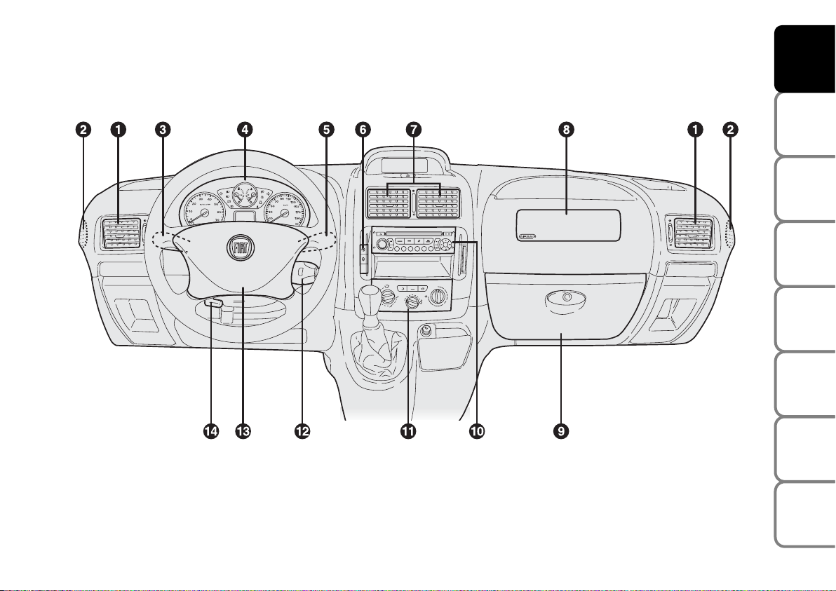
The presence and the position of controls, instruments, gauges and warning lights may vary according to the vehicle version.
1. Side swivel air vents - 2. Side fixed air vents - 3. Left steering column stalk: external lights - 4. Instrument panel -
5. Right steering column stalk: windscreen, rear window and trip computer controls - 6. Dashboard controls - 7. Center swivel air
vents - 8. Front passenger air bag (where provided) - 9. Glovebox - 10. Sound system (where provided) - 11. Heating/ventila-
tion/climate controls - 12. Sound system command lever (where provided) - 13. Front driver’s air bag - 14. Steering wheel adjustment lever
5
SAFETY
DEVICES
CORRECT USE
OF THE
VEHICLE
WARNING
LIGHTS AND
MESSAGES
IN AN
EMERGENCY
VEHICLE
MAINTENANCE
TECHNICAL
SPECIFICATIONS
INDEX
DASHBOARD
AND CONTROLS
F0P0600m
fig. 1
Page 7
6
SAFETY
DEVICES
CORRECT USE
OF THE
VEHICLE
WARNING
LIGHTS AND
MESSAGES
IN AN
EMERGENCY
VEHICLE
MAINTENANCE
TECHNICAL
SPECIFICATIONS
INDEX
DASHBOARD
AND CONTROLS
SYMBOLS
Special coloured labels have been attached
near or actually on some of the components of your Fiat SCUDO. These labels
bear symbols that remind you of the precautions to be taken as regards that particular component.
THE FIAT CODE SYSTEM
To further protect your vehicle from theft,
it has been fitted with an engine immobilising system. This system is automatically
activated when the ignition key is removed.
An electronic device, in fact, is fitted in
each ignition key grip. The device transmits a radio-frequency signal when the engine is started through a special aerial built
into the ignition switch. The modulate signal, which changes each time the engine is
started, is the “password”, by means of
which the control unit recognises the key
and enables to start the engine.
The electronic components
inside the key may be damaged if the key is submitted to
sharp knocks.
OPERATION
Each time the vehicle is started turning the
ignition key to M, the Fiat CODE system
control unit sends a recognition code to
the engine control unit to deactivate the
inhibitor.
The code is sent only if the Fiat CODE
system control unit has recognised the
code transmitted from the key.
Each time the ignition key is turned to S,
the Fiat CODE system deactivates the
functions of the engine electronic control
unit.
In this case, the key should be moved to
S and then back to M; if the lock continues, possibly try again with the other key
provided with the vehicle. If it is still not
possible to start the vehicle, contact Fiat
Dealership.
IMPORTANT Every key has its own code,
which must be memorised by the system
control unit. To memorise new keys, up
to a maximum of eight, apply to Fiat Dealership.
Page 8
7
SAFETY
DEVICES
CORRECT USE
OF THE
VEHICLE
WARNING
LIGHTS AND
MESSAGES
IN AN
EMERGENCY
VEHICLE
MAINTENANCE
TECHNICAL
SPECIFICATIONS
INDEX
DASHBOARD
AND CONTROLS
To refit it proceed as follows:
❒
keep button B pressed and move the
metal insert A;
❒
release button B and turn the metal insert A until hearing the proper locking click.
THE KEYS
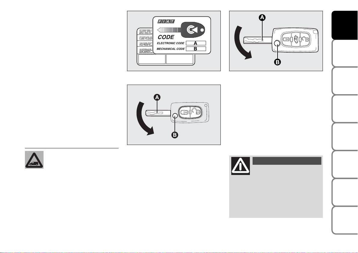
CODE CARD fig. 2
The vehicle is delivered with two copies
of the ignition key and with the CODE
card which bears the following:
A the electronic code;
B the mechanical key code to be given
to the Fiat Dealership when ordering
duplicate keys.
Make sure you have the electronic code
A-fig. 2 with you at all times.
IMPORTANT In order to ensure perfect
efficiency of the electronic devices contained inside the keys, they should never
be exposed to direct sunlight.
All the keys and the CODE
card must be handed over to
the new owner when selling
the vehicle.
fig. 2
F0P0003m
fig. 3
F0P0004m
fig. 3a
F0P0321m
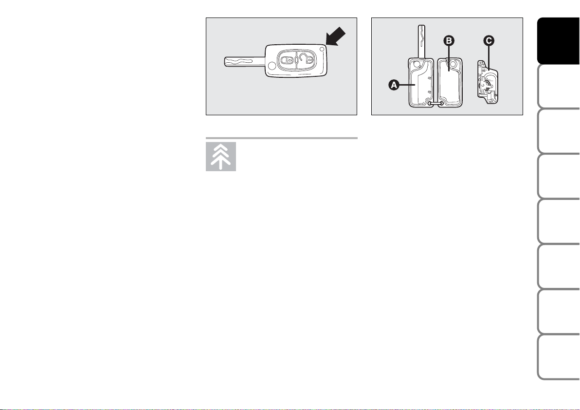
KEY WITH REMOTE CONTROL
fig. 3/a
The metal insert A is retractable and it operates:
❒
ignition switch;
❒
door locks;
❒
fuel filler cap locking/unlocking.
To extract the metal insert, press button
B.
Button B should only be
pressed when the key is
away from the body, in particular
from the eyes and from objects that
can be spoilt (e.g. clothes). Make sure
the key can never be touched by others, especially children, who may inadvertently press the button.
WARNING
Page 9
8
SAFETY
DEVICES
CORRECT USE
OF THE
VEHICLE
WARNING
LIGHTS AND
MESSAGES
IN AN
EMERGENCY
VEHICLE
MAINTENANCE
TECHNICAL
SPECIFICATIONS
INDEX
DASHBOARD
AND CONTROLS
If one of the front doors is open or not
properly closed, central locking cannot
take place.
Dead Lock (where required)
Where provided, pressing twice the remote control button
∫
five seconds after locking the doors will activate the dead
lock (super-locking of the doors).
Dead lock activation is indicated by direction indicators coming on with fixed
light for about two seconds.
The dead lock disables the internal and external handles of the doors.
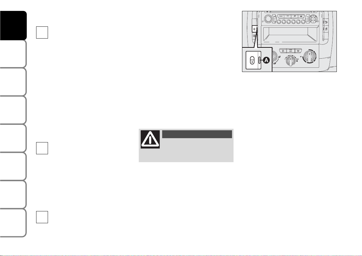
Dashboard led indications
When locking the doors, led A-fig. 4 will
start flashing (deterrence function).
Once doors are locked if one or more
doors are not closed correctly, the instrument panel warning light
9
will turn
on.
fig. 4
F0P0006m
Passenger compartment
Unlocking
By first pressing on this button, it
allows you to unlock the vehicle
passenger compartment doors.
The direction indicator lamps flash twice.
By pressing a second time, it allows the
unlocking of one or more side doors as
well as the rear doors.
This selective opening function is
activated upon the delivery of the vehicle.
Upon request, it is possible to deactivate
the selective opening procedure between
the passenger compartment and the
loading compartment. Please seek advice
from the Fiat Dealership.
Unlocking of loading compartment
By pressing this button all rear
doors are unlocked.
This separation of the locks between
passenger compartment and loading
compartment is a safety device which
allows the closure of the vehicle accesses
of the area from which one is absent.
Centralised locking
By pressing on this command, it
allows the locking of the passenger
compartment and rear doors. The
direction indicator lamps flash once.
∫
`
ª
Never leave passengers inside the vehicle when the
dead lock is active.
WARNING
IMPORTANT If the dead lock is activated from the inside of the vehicle, this will
turn to a simple locking upon starting the
engine.
Page 10
9
SAFETY
DEVICES
CORRECT USE
OF THE
VEHICLE
WARNING
LIGHTS AND
MESSAGES
IN AN
EMERGENCY
VEHICLE
MAINTENANCE
TECHNICAL
SPECIFICATIONS
INDEX
DASHBOARD
AND CONTROLS
Used batteries are harmful to
the environment. They should
be disposed of as specified by
law in the special containers
provided, or take them to a Fiat Dealership, which will deal with their disposal.
fig. 5
F0P0007m
fig. 6
F0P0008m
Request for additional remote
controls
The system can recognise up to 8 remote
controls. Should a new remote control be
necessary, contact a Fiat Dealership taking with you the CODE card, a personal
identity document and the vehicle’s ownership documents.
Replacing the battery of the key
with remote control
Battery replacement:
❒
separate the two casings A and B-fig.
6, by levering in the point shown by the
arrow in fig. 5;
❒
take out the battery and replace it Cfig. 6;
❒
refit both casings, make sure they lock
into place;
Re-initialisation of the remote
control set
After the substitution of batteries or the
disconnection of the battery (vehicle), it is
necessary to re-initialise the remote control set:
❒
Wait at least a minute before using the
remote control set and put it in position A.
❒
Insert the key with the remote control
set into the starting switch.
❒
Within ten seconds, press one of the
two buttons (∫orª) for at least 5
seconds.
❒
Take the key with the remote control
set from the starting switch.
❒
Wait at least a minute before using the
remote control. The remote control
set works once more.
Page 11
10
SAFETY
DEVICES
CORRECT USE
OF THE
VEHICLE
WARNING
LIGHTS AND
MESSAGES
IN AN
EMERGENCY
VEHICLE
MAINTENANCE
TECHNICAL
SPECIFICATIONS
INDEX
DASHBOARD
AND CONTROLS
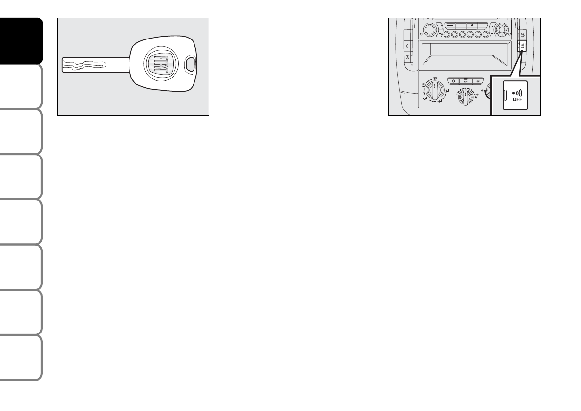
KEY WITHOUT REMOTE
CONTROL fig. 7
The metal insert of the key A is fixed.
The key operates:
❒
ignition switch;
❒
door locks;
❒
fuel filler cap locking/unlocking.
fig. 7
F0P0601m
ALARM
(where provided)
If the vehicle is equipped with alarm, the
following two types of protection can be
activated:
❒
perimetrical (alarm active in case of a
front/back door or the engine bonnet
opening);
❒
volumetric protection (alarm on if the
volume inside the passenger compartment changes).
Activation (complete volumetric
and perimetrical alarm)
❒
Take the key from the switch
❒
Get out of the vehicle
❒
Press the button ∫ (dead lock - once
or twice)
❒
The deterrence led starts to flash.
Activation
(only perimetrical alarm)
❒
Take the key from the switch
❒
Within 10 seconds press the button
fig. 7a keeping it pressed down until
the deterrence led remains switched
on.
❒
Get out of the vehicle.
❒
Press the button ∫ (dead lock - once
or twice).
❒
The deterrence led starts to flash.
fig. 7a
F0P0062m
Alarm deactivation
In order to deactivate the alarm, press the
ª
button, the deterrence led will switch
off.
Page 12

11
SAFETY
DEVICES
CORRECT USE
OF THE
VEHICLE
WARNING
LIGHTS AND
MESSAGES
IN AN
EMERGENCY
VEHICLE
MAINTENANCE
TECHNICAL
SPECIFICATIONS
INDEX
DASHBOARD
AND CONTROLS
The main functions that can be activated with the keys (with or without remote control) are the following:
IMPORTANT Window opening operation is a consequence of a door unlocking control; window closing operation
is a consequence of a door locking control.
Type of key
Key without remote control
Key with remote control
Direction indicators
flashing (only with key with
remote control)
Window
closing
(where
provided)
–
–
Long press
(over 2
seconds)
on button
∫
1 flashing
Door
opening
Key turning
counterclockwise
(driver side and
side sliding door,
where provided)
Key turning
counterclockwise
(driver side and
side sliding door,
where provided)
Press briefly
button
ª
2 flashings
Door closing
form the
outside
Key turning
clockwise
(driver side and
side sliding door,
where provided)
Key turning
clockwise
(driver side and
side sliding door,
where provided)
Press briefly
button
∫
1 flashing
Dead lock
activation
(where
provided)
–
–
Double pressing
on button
∫
3 flashings
Tailgate
opening
(where
provided)
–
–
–
2 flashings
Window
opening
(where
provided)
–
–
Long press
(over 2
seconds)
on button
ª
2 flashings
Page 13
12
SAFETY
DEVICES
CORRECT USE
OF THE
VEHICLE
WARNING
LIGHTS AND
MESSAGES
IN AN
EMERGENCY
VEHICLE
MAINTENANCE
TECHNICAL
SPECIFICATIONS
INDEX
DASHBOARD
AND CONTROLS
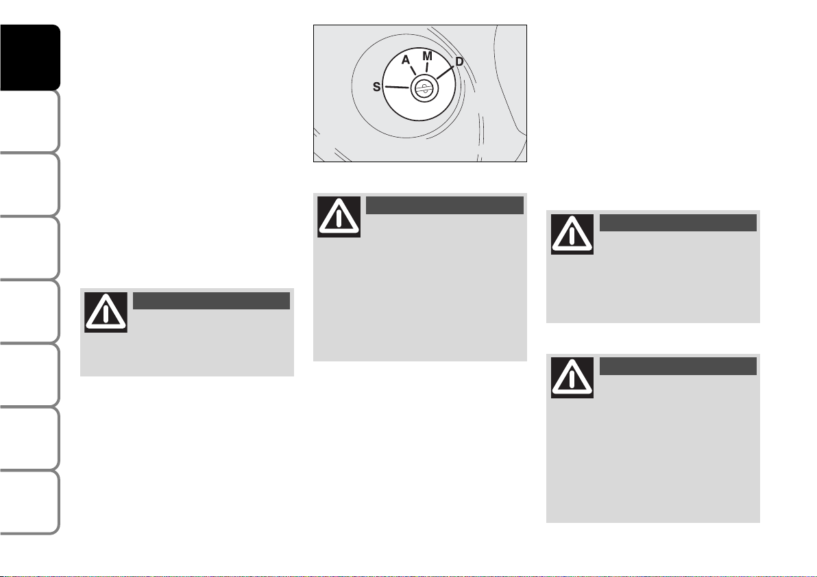
IGNITION
DEVICE
The key can be turned to 4 different positions fig. 8:
❒
S: engine off, key can be removed,
steering column locked.
❒
A: certain electrical devices can work.
❒
M: driving position. All electrical devices are powered.
❒
D: engine starting (unstable position).
STEERING COLUMN LOCK
Engaging
When the key is at S, remove the key and
turn the steering wheel until it locks.
Disengaging
Rock the steering wheel slightly as you
turn the ignition key to M.
If the ignition device is tam-
pered with (e.g.: attempted
theft), have it checked over by a Fiat
Dealership as soon as possible.
WARNING
When getting out of the ve-
hicle, always remove the key
to prevent any occupants from accidentally activating the controls. Remember to engage the handbrake
and if the vehicle is parked on uphill
slope to engage the first gear. If the
vehicle is facing downhill, engage the
reverse gear. Never leave unsupervised children in the vehicle.
WARNING
fig. 8
F0P0010m
Never remove the ignition
key while the vehicle is moving. The steering wheel would automatically lock as soon as you try to
turn it. This also applies when the vehicle is being towed.
WARNING
It is absolutely forbidden to
carry out whatever aftermarket operation involving steering
system or steering column modifications (e.g.: installation of anti-theft
device) that could badly affect performance and safety, cause the lapse
of warranty and also result in noncompliance of the vehicle with homologation requirements.
WARNING
Page 14
13
SAFETY
DEVICES
CORRECT USE
OF THE
VEHICLE
WARNING
LIGHTS AND
MESSAGES
IN AN
EMERGENCY
VEHICLE
MAINTENANCE
TECHNICAL
SPECIFICATIONS
INDEX
DASHBOARD
AND CONTROLS
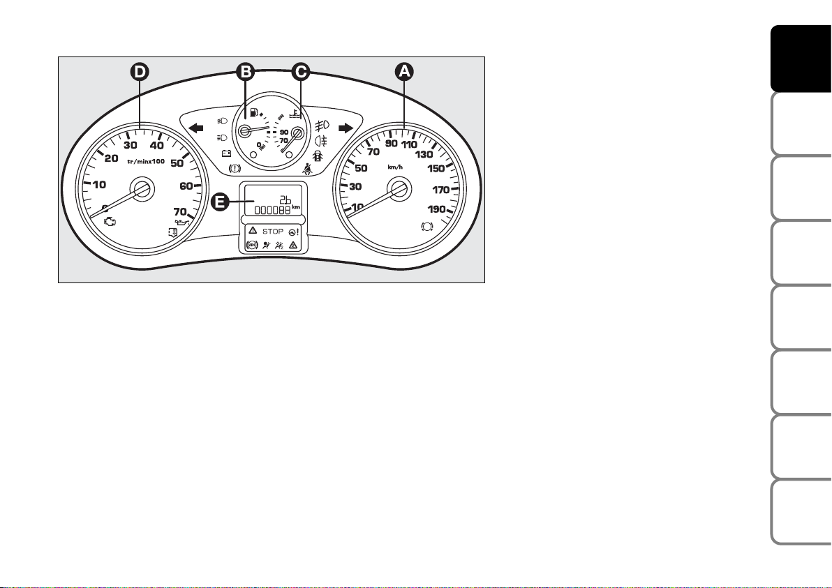
INSTRUMENT PANEL
A Speedometer (speed indicator)
B Fuel level gauge with reserve warning
light
C Engine coolant temperature gauge and
excessive temperature warning light
D Rev counter
E Multifunction display
F0P0012m
fig. 9
Page 15
INSTRUMENTS
Instrument background color and type
may vary according to the version.
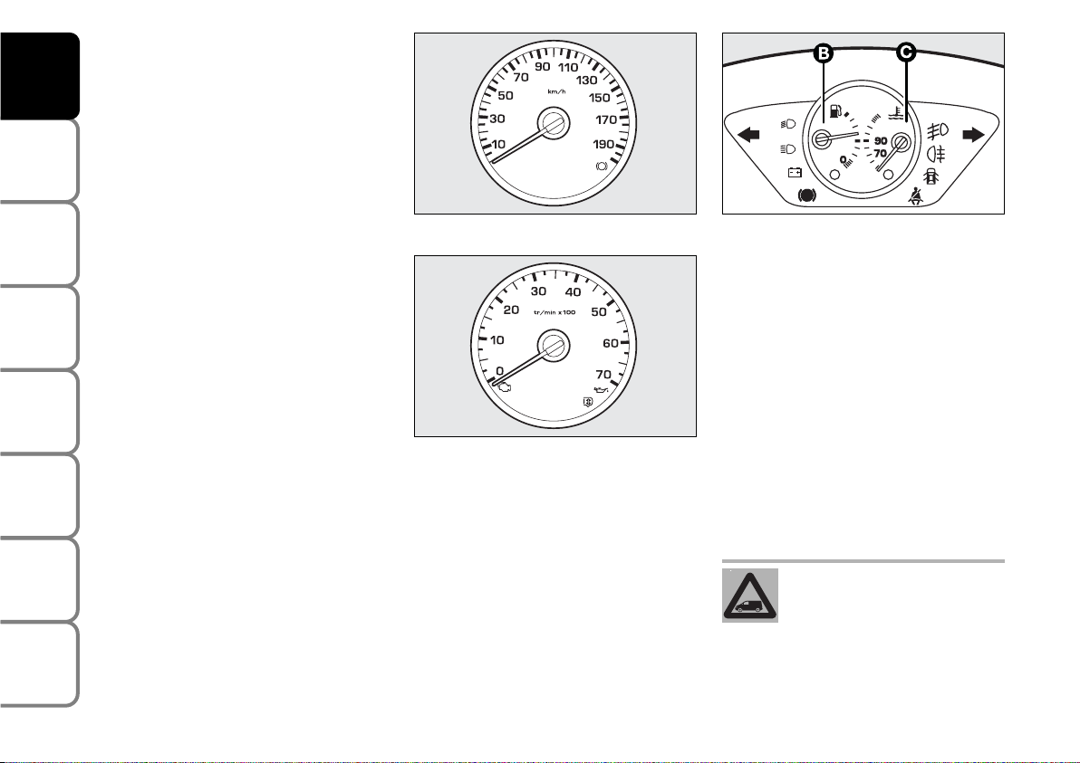
SPEEDOMETER fig. 10
It shows the engine speed.
REV. COUNTER fig. 11/a
Rev counter shows engine rpm.
IMPORTANT The electronic injection control system gradually shuts off the flow of
fuel when the engine is “over-revving” resulting in a gradual loss of engine power.
When the engine is idling, the rev counter
may indicate a gradual or sudden highering of the speed.
This is normal and takes place for example when activating the climate control
system or the fan. In these events a slight
increase in engine idling preserves the battery charge.
FUEL LEVEL GAUGE B-fig. 11/b
This shows the amount of fuel left in the
fuel tank.
K
tank full (See the indications given in
paragraph “At the filling station”).
å tank empty.
The reserve warning light K turns on to
indicate that approximately 7 litres of fuel are left in the tank.
Do not travel with the fuel tank almost
empty: the gaps in fuel delivery could damage the catalyst.
ENGINE COOLANT
TEMPERATURE GAUGE C-fig.
11/b
This shows the temperature of the engine
coolant fluid and begins working when the
fluid temperature exceeds approx. 50°C.
Under normal conditions, the needle
should hover around the middle of the
scale according to the working conditions.
å Low engine coolant temperature.
u High engine coolant temperature.
fig. 10
F0P0013m
14
SAFETY
DEVICES
CORRECT USE
OF THE
VEHICLE
WARNING
LIGHTS AND
MESSAGES
IN AN
EMERGENCY
VEHICLE
MAINTENANCE
TECHNICAL
SPECIFICATIONS
INDEX
DASHBOARD
AND CONTROLS
If the needle reaches the red
area, stop the engine immediately and contact a Fiat
Dealership.
fig. 11/a
F0P0014m
fig. 11/b
1/2
F0P0320m
Page 16
15
SAFETY
DEVICES
CORRECT USE
OF THE
VEHICLE
WARNING
LIGHTS AND
MESSAGES
IN AN
EMERGENCY
VEHICLE
MAINTENANCE
TECHNICAL
SPECIFICATIONS
INDEX
DASHBOARD
AND CONTROLS
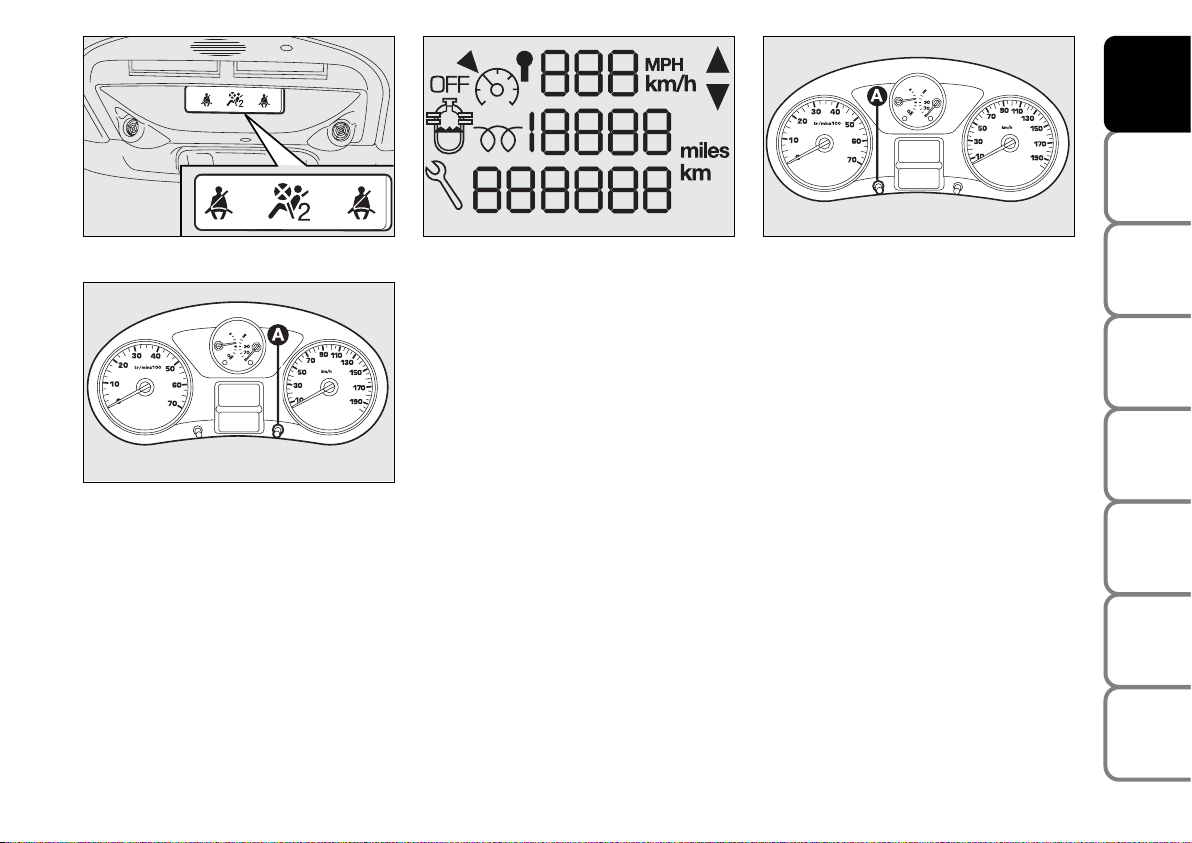
Warning lights on the upper plate
On certain versions, the upper plate fig.
12 (located above the driving mirror) can
be fitted with the following warning lights:
❒
warning light indicating that the seat
belt is not fastened (<) (version with
two front seats).
❒
warning light indicating that the passenger air bag is off (“)
fig. 12
F0P0285m
INSTRUMENT PANEL
BRIGHTNESS ADJUSTER
To adjust the instrument panel brightness:
press button A-fig. 13
DISPLAY
The display fig. 14 shows by the relevant
warning lights (see section “Warning lights
and messages”):
❒
speed limiter / control;
❒
total km / mi covered;
❒
engine oil level gauge;
❒
water in diesel fuel filter;
❒
glow plug preheating.
According to versions the display shows
the time.
Setting the clock through the
instrument panel display
To set the clock through the instrument panel display, use button A-fig. 15 as follows:
❒
turning the button leftwards makes the
minute value flash;
❒
turning the button rightwards will increase minute value (keep the button
turned rightwards to speed up rolling);
❒
turning the button leftwards makes the
hour value flash;
❒
turning the button rightwards will increase hour value (keep the button
turned rightwards to speed up rolling);
❒
turning the button leftwards selects
24H or 12H mode display;
❒
turn the button rightwards to select the
required mode;
❒
turn the button leftwards to stop clock
setting.
If no other setting is made, after about 30
seconds the display will show the time according to the selected settings.
Setting the clock through the
display on the central console
Certain versions are fitted with a central
console with a display showing the time.
To set the clock consult the trip computer under option “Set clock and date”.
fig. 14
F0P0291m
fig. 15
1/2
F0P0292m
fig. 13
1/2
F0P0353m
Page 17
16
SAFETY
DEVICES
CORRECT USE
OF THE
VEHICLE
WARNING
LIGHTS AND
MESSAGES
IN AN
EMERGENCY
VEHICLE
MAINTENANCE
TECHNICAL
SPECIFICATIONS
INDEX
DASHBOARD
AND CONTROLS
MAINTENANCE
INDICATOR
It regulates the intervals between the maintenance operations based on vehicle use.
Functioning
As soon as the starting key is inserted and
for a few seconds, the maintenance key lights
up and which indicates the maintenance operations; the total odometer display indicates
the number of kilometres {rounded down}
which can be covered until the next maintenance operation. The maintenance expiry
dates are calculated starting from the last resetting of the indicator.
This expiry date is determined by means
of two parameters:
❒
the distance in kilometres covered
❒
time which has passed since the last
maintenance operation.
The distance in kilometres
which remains to be covered
can be considered by the time
factor, based on the driver’s
driving habits.
F0P0354m
F0P0355m
OIL OK
F0P0356m
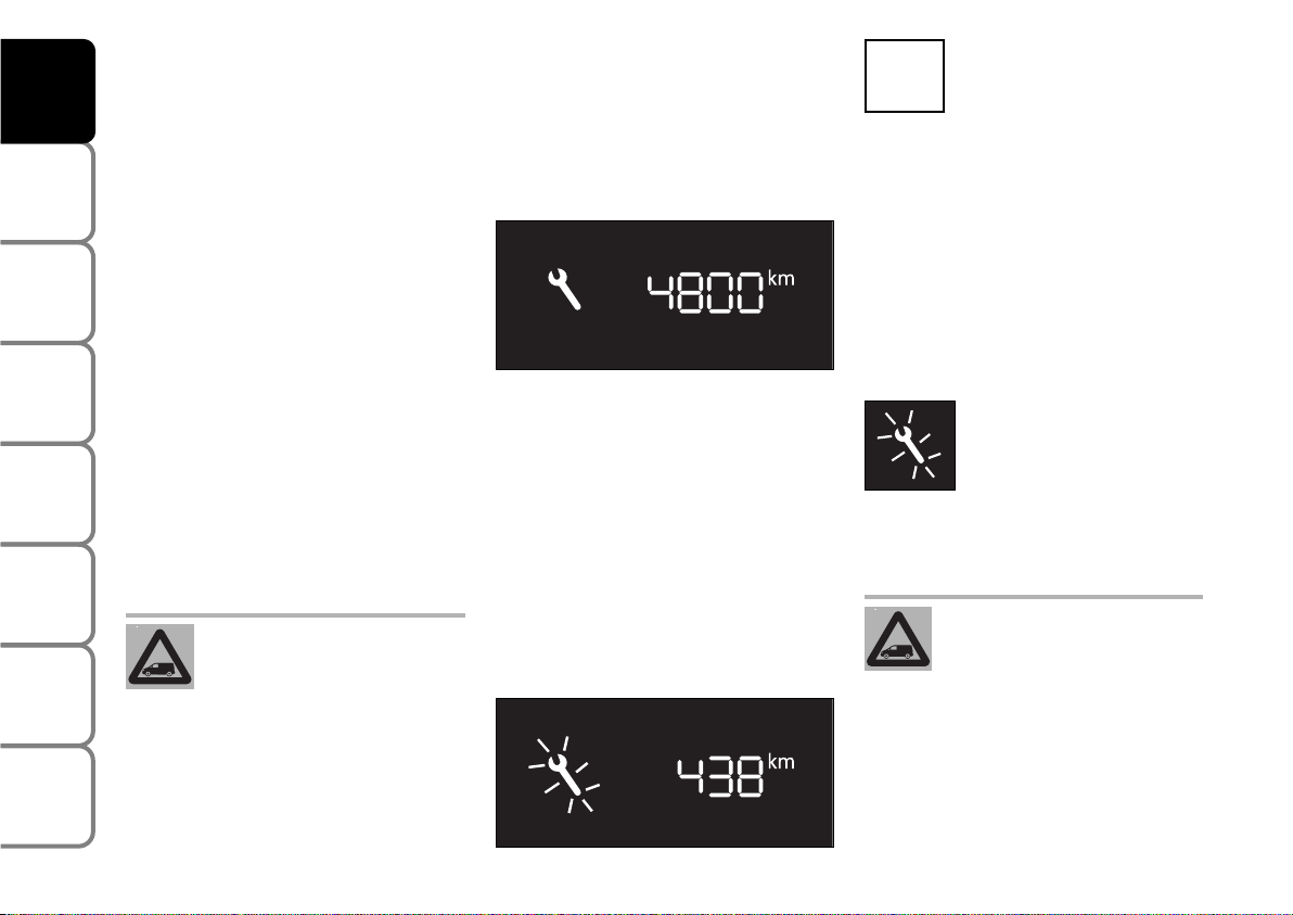
Maintenance expiry date over
1,000 km
Example: one can still travel 4,800 km before the next maintenance operation. After having turned the starting key to the
M position and for a few seconds, the display indicates:
A few seconds after having turned the
starting key to the M position, the oil level is shown, therefore the total odometer
works again and it indicates the total and
daily amount of kilometres travelled.
Maintenance expiry date less than
1,000 km
After having turned the starting key to the
M position and for a few seconds, the
maintenance key flashes and the remaining number of kilometres is shown.
ENGINE OIL LEVEL
INDICATOR
Turning the starting key to the
M position, the instrument, after having
shown the kilometres to be covered before the next maintenance operation, supplies the synchronised indication of the oil
level present in the engine oil pan. The
flashing of the word “OIL”, accompanied
by a beeping and by a message, indicates
an insufficient quantity of oil in the engine.
The flashing of the word “OIL –“ indicates
a problem with the engine oil sensor.
Maintenance Expiry date exceeded
After having turned the
starting key to the M position and for a few seconds,
the maintenance key flashes
and the number of kilometres
travelled after the expiry date of the maintenance operation is shown.
When the engine is running, the
maintenance key remains
switch until the maintenance
operation has been carried out.
Before the two expiry dates are reached:
the maintenance key lights up also when
the expiry date of two years has been exceeded.
Page 18
17
SAFETY
DEVICES
CORRECT USE
OF THE
VEHICLE
WARNING
LIGHTS AND
MESSAGES
IN AN
EMERGENCY
VEHICLE
MAINTENANCE
TECHNICAL
SPECIFICATIONS
INDEX
DASHBOARD
AND CONTROLS
Distance to cover
This value shows the distance to be covered yet, under active navigation condition.
Trip distance
This value shows the distance covered
from the start of the journey, after resetting (Reset).
Average consumption
This value shows the average consumption from the start of the journey, after
resetting (Reset).
Average speed
This value shows the vehicle average
speed calculated from the start of the
journey, after resetting (Reset).
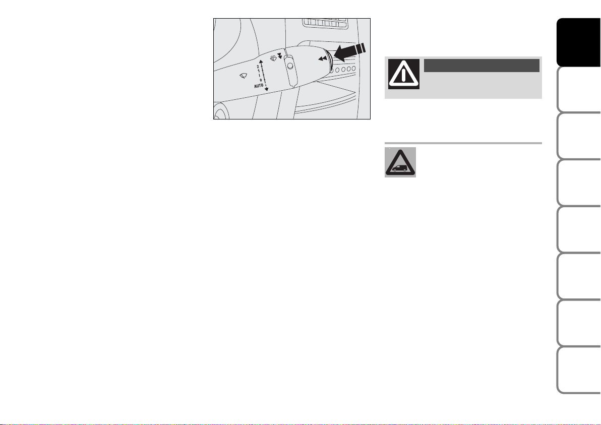
TRIP COMPUTER
The trip computer enables to display in sequence, by pressing repeatedly button
fig. 16 set on the top of the steering column stalk, the following values:
range, instant consumption, distance
to cover, trip 1 (trip distance, average consumption, average speed)
and trip 2 (trip distance, average
consumption, average speed).
This information is displayed on the display of the infotelematic CONNECT system.
Reset: press button shown in fig. 16 for
over 2 seconds for resetting.
Range
This value shows the distance in km (or
mi) that the vehicle can still cover before
needing fuel, assuming that driving conditions are kept unvaried.
Instant consumption
This value shows average fuel consumption calculated during the last seconds of
travel.
fig. 16
F0P0041m
FRONT SEATS
Only make adjustments when
the vehicle is stationary.
WARNING
Fabric upholstery of your Fiat
SCUDO is purpose-made to
withstand common wear re-
sulting from normal use of the
vehicle. It is however absolutely necessary to prevent hard and/or prolonged
scratching/scraping caused by clothing
accessories like metallic buckles, studs,
“Velcro” fixings, etc. that stressing locally the fabric could break yarns and
damage the upholstery as a consequence.
Page 19
18
SAFETY
DEVICES
CORRECT USE
OF THE
VEHICLE
WARNING
LIGHTS AND
MESSAGES
IN AN
EMERGENCY
VEHICLE
MAINTENANCE
TECHNICAL
SPECIFICATIONS
INDEX
DASHBOARD
AND
CONTROLS
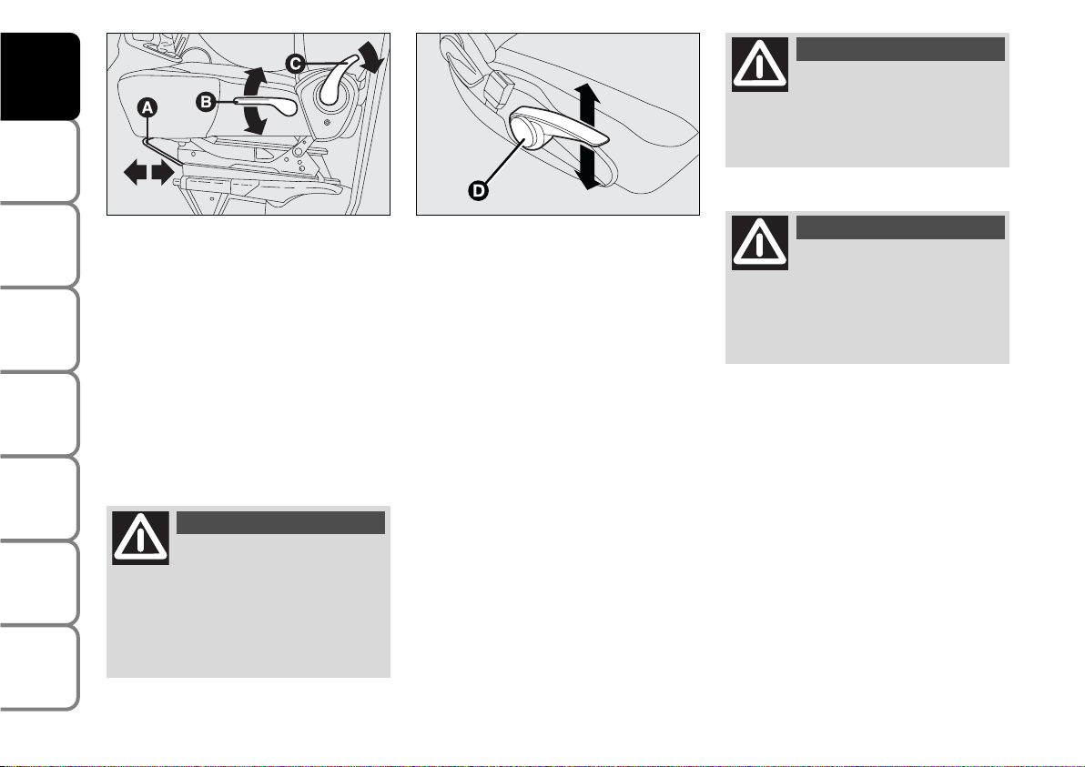
Moving the seat backwards or
forwards fig. 17
Lift the lever A and push the seat forwards
or backwards: in the driving position the
arms should rest on the rim of the steering wheel. Once you have released the
lever, check that the seat is firmly locked
in the runners by trying to move it back
and forth.
Once you have released the
lever, check that the seat is
firmly locked in the runners by trying
to move it back and forth. Failure to
lock the seat in place could result in
the seat moving suddenly and the driver losing control of the vehicle.
WARNING
For maximum safety, keep
the back of your seat upright, lean back into it and make sure
the seat belt fits closely across your
chest and hips.
WARNING
Regulation of the height of the
driver’s seat fig. 17-18
Depending on the version and the configuration of the vehicle, it is equipped with:
❒
a passive regulation: pull lever B
upwards, therefore get off the seat in
order to allow it to rise.
❒
an active regulation: pull lever D
upwards or downwards until the
desired position is desired.
Back rest angle adjustment fig. 17
Use lever C and adjust the back rest.
Do not remove the seats or
carry out servicing and/or repair operations since incorrect operations could impair the regular operation of safety devices: always contact Fiat Dealership.
WARNING
fig. 17
F0P0015m
fig. 18
F0P0322m
Page 20
19
SAFETY
DEVICES
CORRECT USE
OF THE
VEHICLE
WARNING
LIGHTS AND
MESSAGES
IN AN
EMERGENCY
VEHICLE
MAINTENANCE
TECHNICAL
SPECIFICATIONS
INDEX
DASHBOARD
AND CONTROLS
fig. 18/a
F0P0016m
fig. 19
A
B
F0P0017m
fig. 20
F0P0018m
fig. 21
F0P0019m
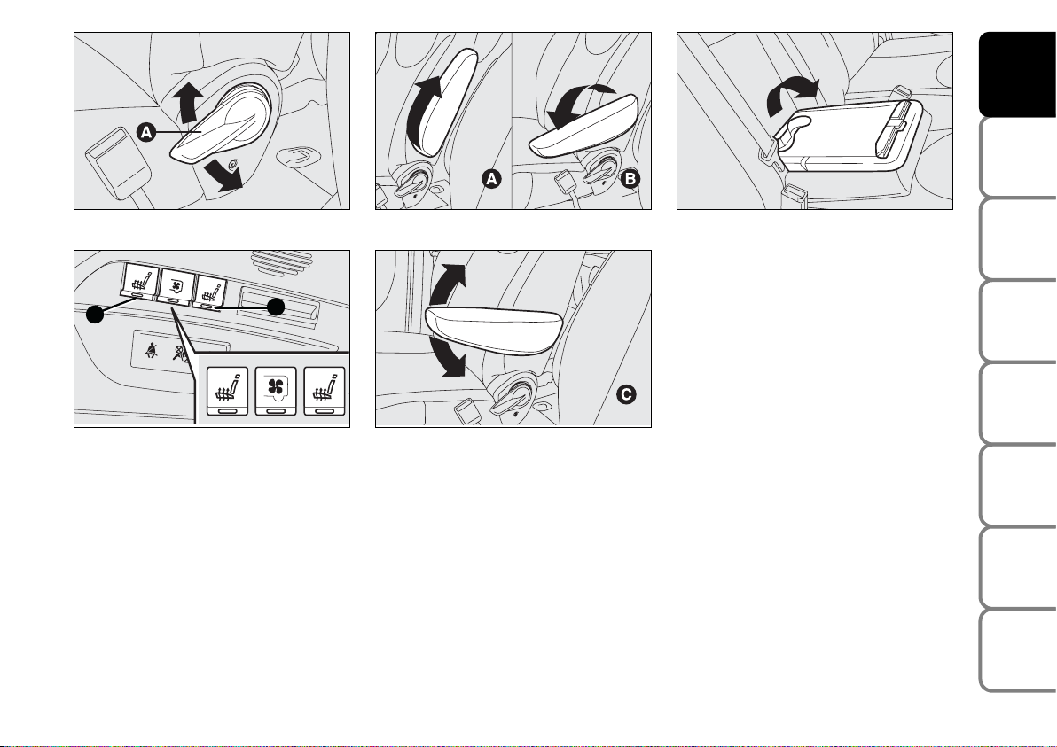
Lumbar adjustment
(where provided) fig. 18/a
Use lever A to adjust the seat as required.
Seat warming
(where provided) fig. 19
With ignition key at M, press button A or B
(driver’s side or passenger’s side) to switch the
seat warming on/off. The led on the button will
light up when the function is on.
FRONT ARMRESTS
(where provided) fig. 20-21
Certain versions are fitted with two
armrests between front seats.
To adjust the armrests proceed as follows:
❒
raise the armrest and bring it to position A;
❒
lower the armrest and bring it down
to completely to position B;
❒
raise the armrest again and bring it to the
required position C.
fig. 22
F0P0122m
FRONT TWO-SEAT
BENCH (where provided)
It is fix and it is fitted with three point belt
and belt retractor.
It can be fitted with a folding shelf fig. 22
to be used like supporting surface. Pull the
tab to use it.
Page 21
20
SAFETY
DEVICES
CORRECT USE
OF THE
VEHICLE
WARNING
LIGHTS AND
MESSAGES
IN AN
EMERGENCY
VEHICLE
MAINTENANCE
TECHNICAL
SPECIFICATIONS
INDEX
DASHBOARD
AND
CONTROLS
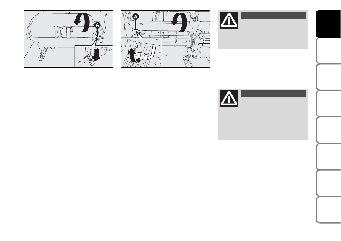
FOLDING, REMOVING AND
REFITTING THE REAR BENCH
SEAT
To remove and then to re-
fit the bench seat, keep
the back rest firmly lowered and
flattened against the cushion to
prevent any contact between the
seat articulation mechanisms.
WARNING
REAR SEATS
Single seat
This seat can be folded to facilitate access
to the rear area and it can be removed.
Certain versions can be fitted with a shelf
obtained in the back of the seat.
To use it, operate the release lever A-fig.
23 and guide the seat back onto the cushion.
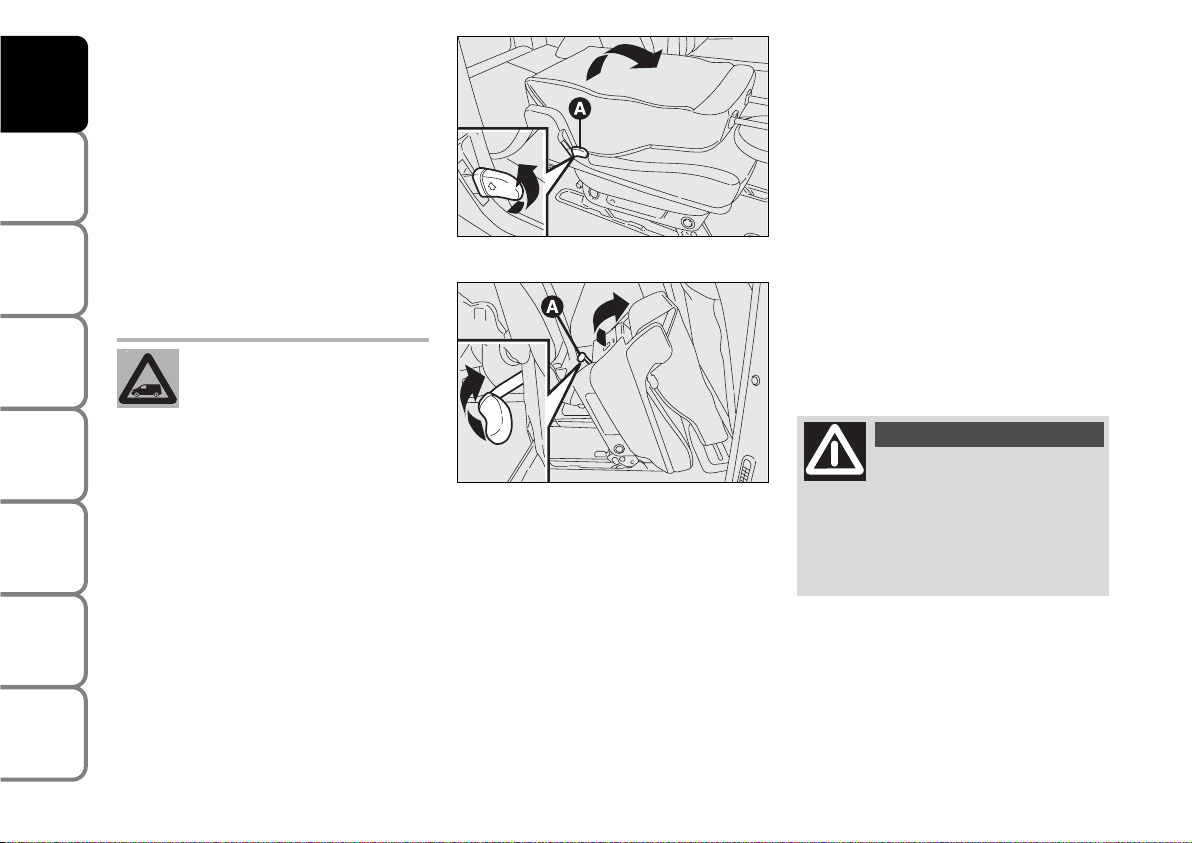
Folding/removing the single seat
To fold the back of the seat pull handle Afig. 23 upwards.
To remove the seat proceed as follows:
❒
operate handle A-fig. 24 and guide
the seat forward as shown in the figure;
❒
lift the seat to make the pins come
out of their anchorings and then
remove it taking care to keep the
back rest firmly lowered and flattened
against the cushion.
fig. 23
F0P0022m
fig. 24
F0P0023m
To remove and then to refit
the seat keep the back rest
firmly lowered and flattened
against the cushion to prevent any contact between the seat articulation mechanisms.
TWO-SEAT BENCH
According to versions it can be of different types:
❒
2-seat bench with fix back rest;
❒
removable 2-seat bench with back
rests wrapping individually;
❒
removable 2-seat bench with back
rests folding individually or wrapping
in “table” position.
Page 22
21
SAFETY
DEVICES
CORRECT USE
OF THE
VEHICLE
WARNING
LIGHTS AND
MESSAGES
IN AN
EMERGENCY
VEHICLE
MAINTENANCE
TECHNICAL
SPECIFICATIONS
INDEX
DASHBOARD
AND CONTROLS
To fold the back rest pull lever A-fig. 25.
To remove the seat proceed as follows:
– lower the head restraints completely;
fig. 25
F0P0024m
fig. 26
F0P0025m
– fold the back rest as described previously;
– lift lever A-fig. 26 and fold the seat;
– lift the seat to make the pins come out
of their anchorings and remove it taking
care to keep the back rest firmly lowered
and flattened against the cushion.
To refit the seat proceed as follows:
– lift the bench seat and secure the pins to
their anchorings on the floor, make sure
they lock properly into place;
– guide the bench seat until rear anchorings lock automatically.
Make sure the floor an-
choring seats are always
clean; foreign matters could impair
proper seat anchoring.
WARNING
Before starting to drive
make sure all seats are
facing the running direction and
perfectly anchored. Only this position ensures the effectiveness of
seat belts.
WARNING
Page 23
22
SAFETY
DEVICES
CORRECT USE
OF THE
VEHICLE
WARNING
LIGHTS AND
MESSAGES
IN AN
EMERGENCY
VEHICLE
MAINTENANCE
TECHNICAL
SPECIFICATIONS
INDEX
DASHBOARD
AND
CONTROLS
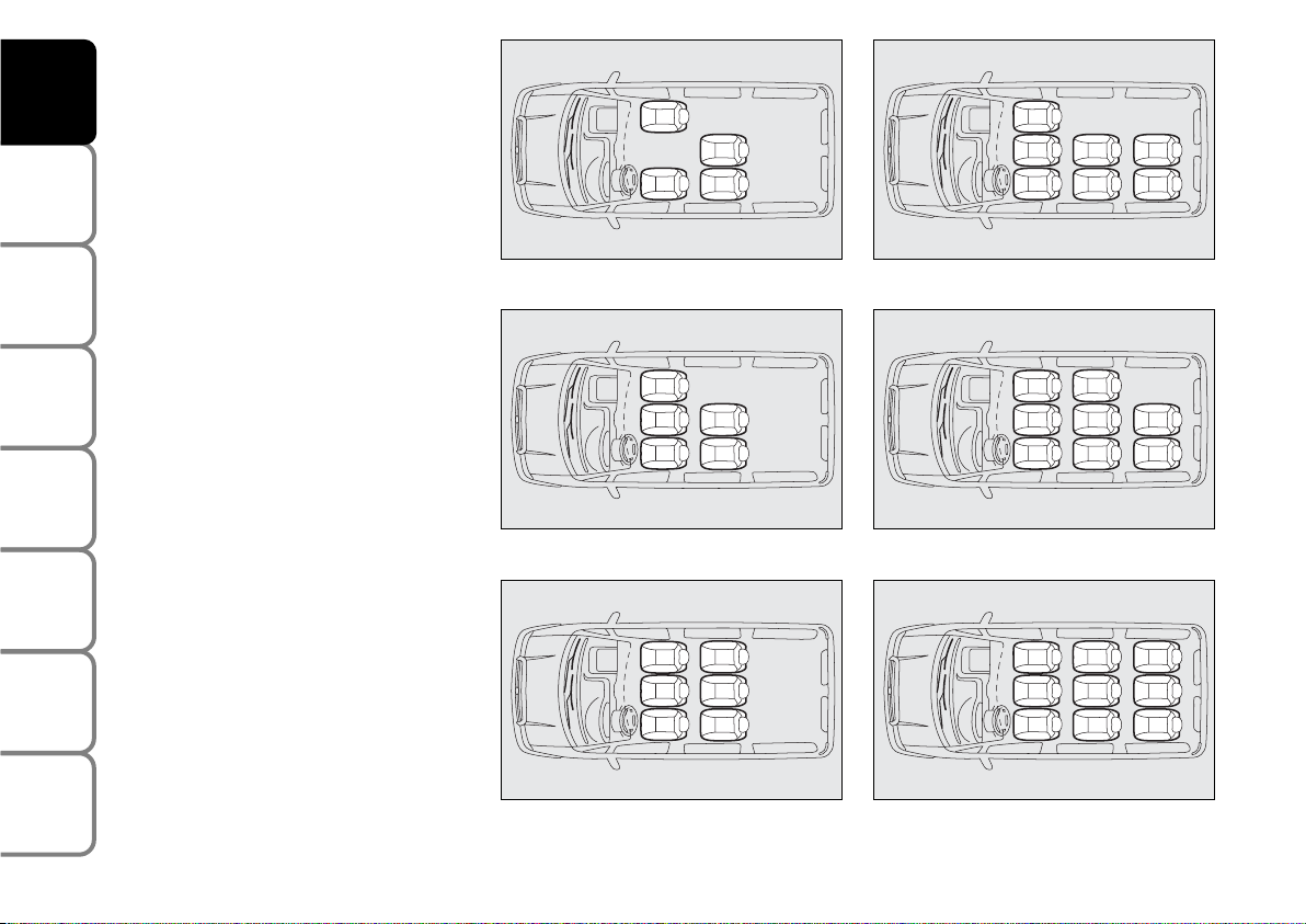
SEAT ARRANGEMENTS
Depending on the various versions it is
possible to vary the seat arrangement using the relevant preset housings on the
floor.
The following figures show some configurations that can be obtained according to
the version requested.
F0P0123m
fig. 27 - 4 seats
F0P0124m
F0P0125m
fig. 28 - 5 seats
fig. 29 - 6 seats
F0P0126m
F0P0127m
F0P0128m
fig. 30 - 7 seats
fig. 31 - 8 seats
fig. 32 - 9 seats
Page 24

23
SAFETY
DEVICES
CORRECT USE
OF THE
VEHICLE
WARNING
LIGHTS AND
MESSAGES
IN AN
EMERGENCY
VEHICLE
MAINTENANCE
TECHNICAL
SPECIFICATIONS
INDEX
DASHBOARD
AND CONTROLS
HEAD RESTRAINTS
To raise:
❒
raise the head restraint until hearing the
locking click.
To lower:
❒
press buttons A-fig. 33 or A-fig. 34
and lower the head restraint.
Remember that the head re-
straints should be adjusted
to support the back of your head and
not your neck. Only in this position
do they exert their protective action
WARNING
IMPORTANT Following a different seat
layout:
❒
if you take the head rest off, replace it
ad fix it to a support
❒
check that the safety belts are still accessible and easy for the passenger to
fasten
❒
a passenger must never travel without
having correctly regulated the head rest
or without having regulated and fastened the safety belt.
ATTENTION fig. 32/a
Whilst you are driving, it is forbidden to
carry a passenger:
❒
in third row if the backboard placed in
front (second row) is in the table position;
❒
in third row if the seat/coach placed in
front (second row) is in a folded position;
❒
on the centre seat if the right side seat
is in a folded position.
fig. 32/a
F0P0323m
Page 25
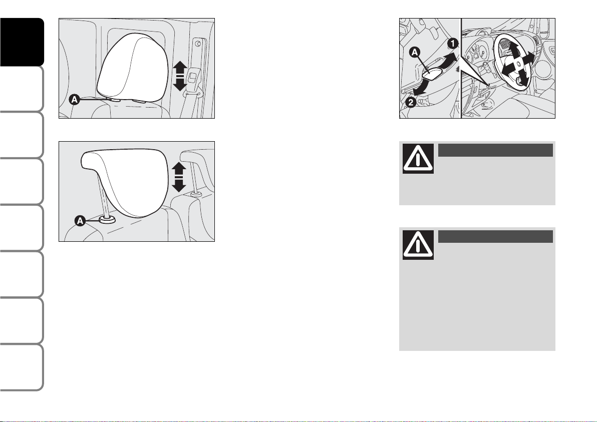
STEERING WHEEL
The driver can adjust the steering wheel
position both axially and in height.
To adjust the armrests proceed as follows:
❒
release the lever A-fig. 35 pushing it
forwards (position 2);
❒
adjust the steering wheel as required;
❒
lock the lever A pulling it towards the
steering wheel (position 1).
fig. 35
F0P0028m
Any adjustment of the steer-
ing wheel position must be
carried out only with the vehicle stationary and the engine turned off.
WARNING
It is absolutely forbidden to
carry out whatever aftermarket operation involving steering
system or steering column modifications (e.g.: installation of anti-theft
device) that could badly affect performance and safety, cause the lapse
of warranty and also result in noncompliance of the vehicle with homologation requirements.
WARNING
24
SAFETY
DEVICES
CORRECT USE
OF THE
VEHICLE
WARNING
LIGHTS AND
MESSAGES
IN AN
EMERGENCY
VEHICLE
MAINTENANCE
TECHNICAL
SPECIFICATIONS
INDEX
DASHBOARD
AND
CONTROLS
fig. 33
F0P0026m
fig. 34
F0P0027m
To optimise head restraint protective action, adjust the seat back upright and keep
your head as close as possible to the head
restraint.
Page 26
25
SAFETY
DEVICES
CORRECT USE
OF THE
VEHICLE
WARNING
LIGHTS AND
MESSAGES
IN AN
EMERGENCY
VEHICLE
MAINTENANCE
TECHNICAL
SPECIFICATIONS
INDEX
DASHBOARD
AND CONTROLS
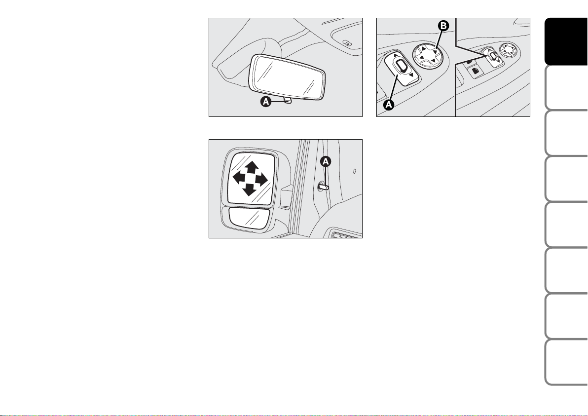
REARVIEW MIRRORS
DRIVING MIRROR fig. 36
The mirror is fitted with a safety device
that causes it to be released in the event
of a violent crash.
It can be adjusted through lever A-fig. 36:
❒
normal position
❒
antiglare position.
fig. 36
F0P0029m
fig. 37
F0P0030m
DOOR MIRRORS
Manual adjustment fig. 37
Use knob A.
fig. 38
F0P0031m
Electrical adjustment fig. 38
The mirrors can only be adjusted electrically when the key is at M.
To adjust the armrests proceed as follows:
❒
use switch A to select the mirror required (left or right);
❒
to adjust the mirror move the switch B
in the four directions;
Electrical folding fig. 38
It is possible only with the starting key in
the M position.
Take switch A to the central position,
therefore move switch B backwards.
Page 27
26
SAFETY
DEVICES
CORRECT USE
OF THE
VEHICLE
WARNING
LIGHTS AND
MESSAGES
IN AN
EMERGENCY
VEHICLE
MAINTENANCE
TECHNICAL
SPECIFICATIONS
INDEX
DASHBOARD
AND
CONTROLS
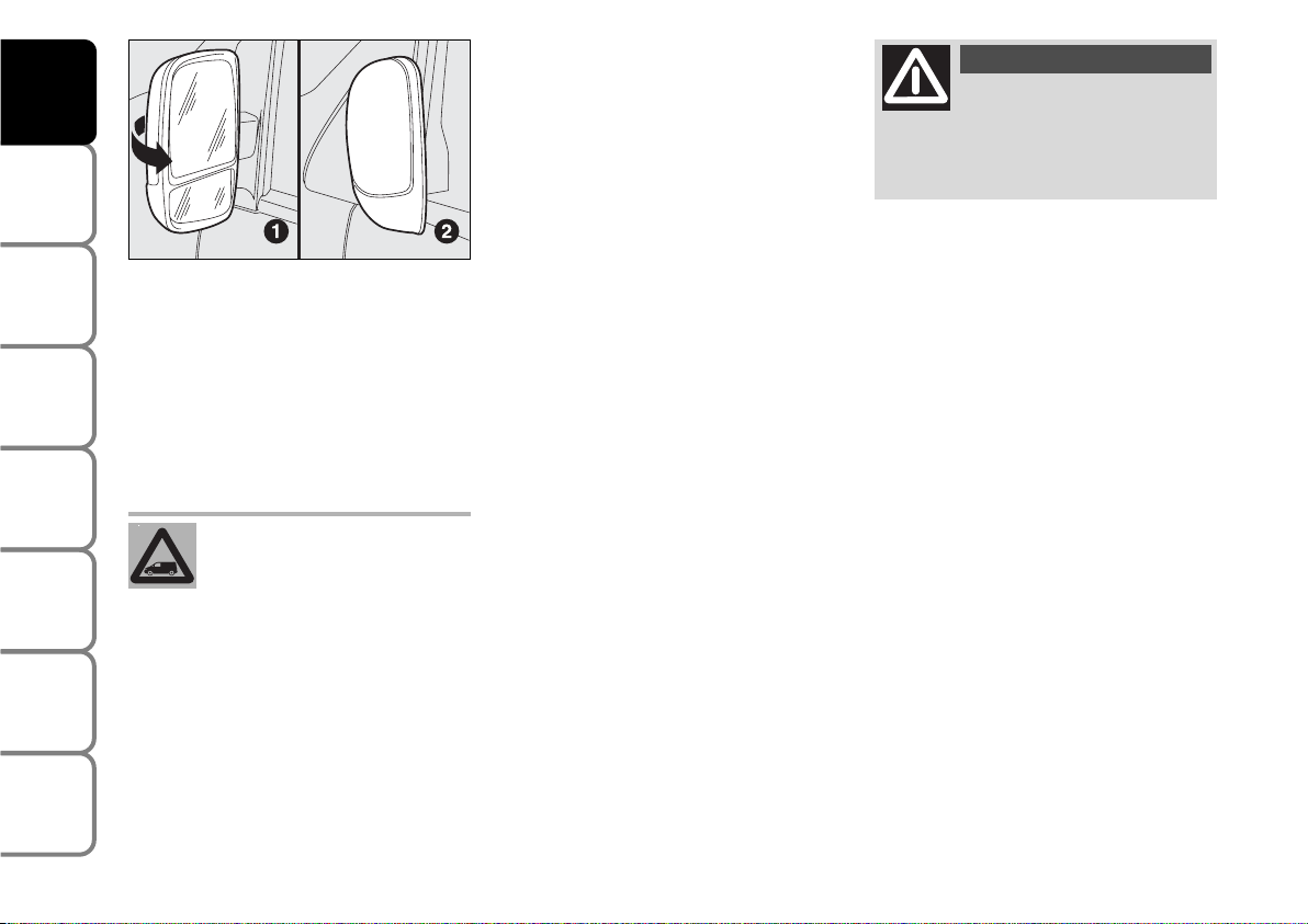
Folding
When required (for example when the
mirror causes difficulty in narrow spaces)
it is possible to fold the mirror moving it
from position 1-fig. 39 to position 2.
When driving the mirrors shall
always be in position 1-fig. 39.
The lower part of the exter-
nal rear-view mirror on the
driver’s side, with it being curved, it
slightly alters the perception of distance.
WARNING
Demisting/defrosting
(where provided)
Mirrors are fitted with resistors that will
activate when turning the heated rear window on (by pressing button
(
).
IMPORTANT This function is timed and
it will turn off automatically a few minutes
later.
fig. 39
F0P0032m
Page 28
27
SAFETY
DEVICES
CORRECT USE
OF THE
VEHICLE
WARNING
LIGHTS AND
MESSAGES
IN AN
EMERGENCY
VEHICLE
MAINTENANCE
TECHNICAL
SPECIFICATIONS
INDEX
DASHBOARD
AND CONTROLS
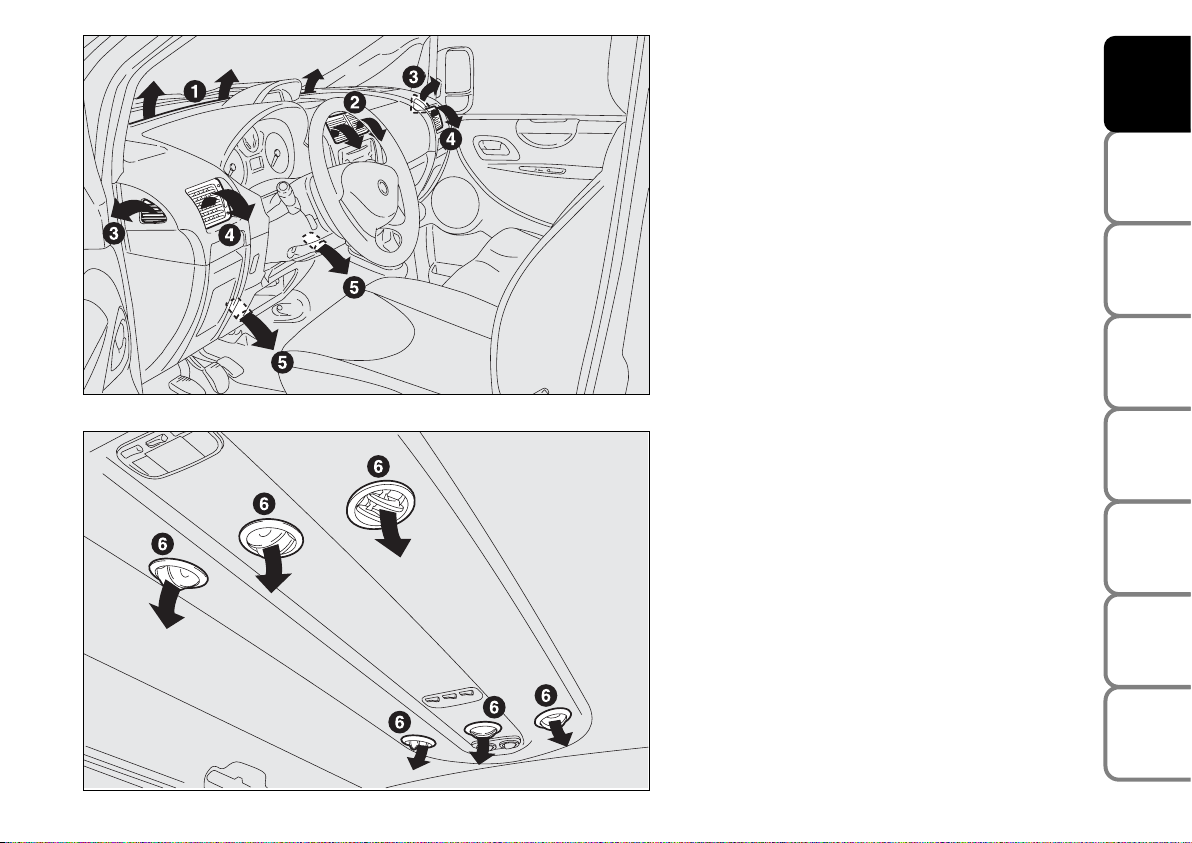
HEATING AND VENTILATION
1. Fixed upper vent
2. Central swivel vents
3. Fixed side vents
4. Side swivel vents
5. Lower vents for front seats
6. Upper vents for rear seats
(where provided).
fig. 40
F0P0033m
fig. 41
F0P0101m
Page 29
28
SAFETY
DEVICES
CORRECT USE
OF THE
VEHICLE
WARNING
LIGHTS AND
MESSAGES
IN AN
EMERGENCY
VEHICLE
MAINTENANCE
TECHNICAL
SPECIFICATIONS
INDEX
DASHBOARD
AND
CONTROLS
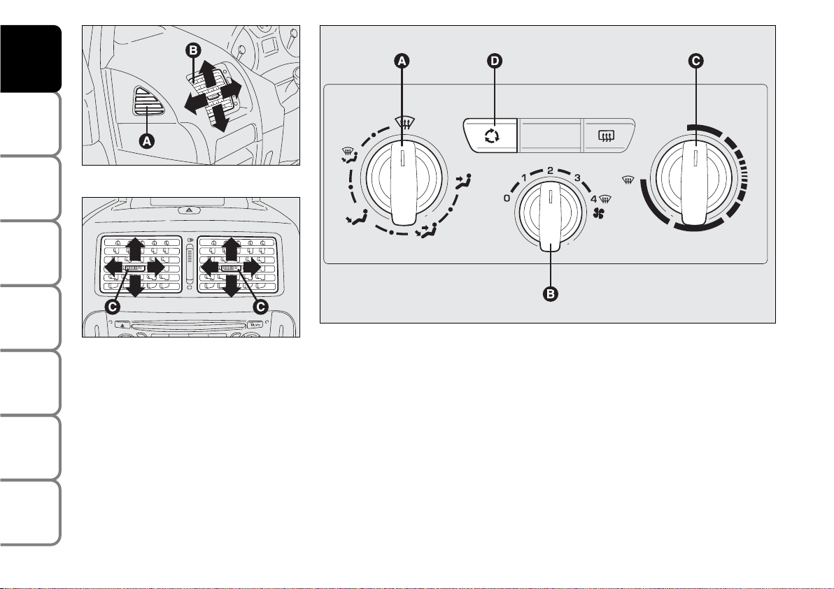
CONTROLS fig. 44
Air distribution slider A
µ
to convey air to the centre and side
vents;
∑
to warm the feet and convey cooler
air to the dashboard vents, in intermediate temperature conditions;
∂
to heat with outside harsh temperature: to convey as much air as possible to the feet;
∏
to warm the feet and at the same time
demist the windscreen;
-
for quick windscreen demisting.
fig. 44
F0P0036m
fig. 42
F0P0034m
fig. 43
F0P0035m
SIDE AND CENTRAL VENTS
fig. 42-43
Vents can be directed in the four positions
shown by the arrows.
A Fixed vent for side windows.
B Side adjustable vents.
C Centre adjustable vents.
Vents A are fixed.
To use vents B and C, operate the relevant device to turn them as required.
Page 30

29
SAFETY
DEVICES
CORRECT USE
OF THE
VEHICLE
WARNING
LIGHTS AND
MESSAGES
IN AN
EMERGENCY
VEHICLE
MAINTENANCE
TECHNICAL
SPECIFICATIONS
INDEX
DASHBOARD
AND CONTROLS
Fan activation /speed adjustment
knob B
0 = fan off
1-2-3 = fan speed
4
-p=
max. fan speed
Air temperature slider C (mixing
hot and cold air)
Red section = hot air
Blue section = cold air
Air recirculation on/off button D
Press the button to turn air recirculation
on.
Press the button again to turn air recirculation off.
FAST HEATING
For fast heating of the passenger compartment, proceed as follows:
❒
turn slider C to red section;
❒
turn air recirculation on (if off);
❒
turn slider A to ∂;
❒
turn slider B to 4 -p (max. fan
speed).
Then use the controls to keep the required comfort conditions and press button D to turn air recirculation off and to
prevent misting up.
IMPORTANT With cold engine, you have
to wait for a few minutes to let the system fluid reach the operating temperature.
VENTILATION
To ventilate the passenger’s compartment
properly proceed as follows:
❒
turn slider C to blue section;
❒
turn air recirculation off (if on);
❒
turn slider A to µ;
❒
slider B turned to the required speed.
WARMING THE PASSENGER
COMPARTMENT
Proceed as follows:
❒
turn slider C to red section;
❒
turn slider A to the required position;
❒
slider B turned to the required speed.
Page 31

30
SAFETY
DEVICES
CORRECT USE
OF THE
VEHICLE
WARNING
LIGHTS AND
MESSAGES
IN AN
EMERGENCY
VEHICLE
MAINTENANCE
TECHNICAL
SPECIFICATIONS
INDEX
DASHBOARD
AND
CONTROLS
FRONT WINDOW FAST
DEMISTING/
DEFROSTING (WINDSCREEN
AND SIDE WINDOWS)
Proceed as follows:
❒
turn slider C to red section;
❒
turn air recirculation off (if on);
❒
turn slider A to
-;
❒
turn slider B to 4 -p (max. fan
speed).
After demisting/defrosting, operate the
controls to restore the required comfort.
Window demisting
In the event of considerable outside moisture and/or rain and/or considerable differences in temperature inside and outside
the passenger compartment, perform the
following preventive demisting procedure:
❒
turn slider C to red section;
❒
turn air recirculation off by pressing
button D (if off);
❒
turn slider A to -or to ∏if the windows do not demist;
❒
turn slider B to 2ndspeed.
HEATED REAR WINDOW AND
DOOR MIRROR
DEMISTING/DEFROSTING
(where provided) fig. 45
Press button A to start this function;
when this function is on the button led is
on.
This function is timed and switches off automatically after 20 minutes. To cut out
this function press again button A.
IMPORTANT Do not apply stickers on
the inside of the rear window over the
heating filaments to avoid damage that
might cause it to stop working properly.
fig. 45
F0P0037m
Page 32

31
SAFETY
DEVICES
CORRECT USE
OF THE
VEHICLE
WARNING
LIGHTS AND
MESSAGES
IN AN
EMERGENCY
VEHICLE
MAINTENANCE
TECHNICAL
SPECIFICATIONS
INDEX
DASHBOARD
AND CONTROLS
MANUAL CLIMATE
CONTROL SYSTEM
(where provided)
CONTROLS fig. 46
Air distribution slider A
µ
to convey air to the centre and side
vents;
∑
to warm the feet and convey cooler
air to the dashboard vents, in intermediate temperature conditions;
∂
to heat with outside harsh temperature: to convey as much air as possible to the feet;
∏
to warm the feet and at the same time
demist the windscreen;
-
for quick windscreen demisting.
Fan activation /speed adjustment
knob B
0 = fan off
1-2-3 = fan speed
4
-p=
max. fan speed
AIR RECIRCULATION fig. 44
Turn this function on by pressing button
Ω
.
This function is particularly useful when
the outside air is heavily polluted (in a traffic jam, tunnel etc.). However, it is better
not to use it for long periods, especially
if there are several people in the vehicle.
IMPORTANT The inside air recirculation
system makes it possible to reach the required “heating” or “cooling” conditions
faster.
Do not use the air recirculation function
on rainy/cold days as it would considerably increase the possibility of the windows misting inside.
Page 33

32
SAFETY
DEVICES
CORRECT USE
OF THE
VEHICLE
WARNING
LIGHTS AND
MESSAGES
IN AN
EMERGENCY
VEHICLE
MAINTENANCE
TECHNICAL
SPECIFICATIONS
INDEX
DASHBOARD
AND
CONTROLS
Air temperature slider C
(mixing hot and cold air)
Red section = hot air
Blue section = cold air
Climate control system on/off
button E
Press the button (button led on) to turn
climate control system on.
Press the button again (button led off) to
turn climate control system off.
fig. 46
F0P0038m
Air recirculation on/off button D
Press the button to turn air recirculation
on.
Press the button again to turn air recirculation off.
Page 34

33
SAFETY
DEVICES
CORRECT USE
OF THE
VEHICLE
WARNING
LIGHTS AND
MESSAGES
IN AN
EMERGENCY
VEHICLE
MAINTENANCE
TECHNICAL
SPECIFICATIONS
INDEX
DASHBOARD
AND CONTROLS
VENTILATION
To ventilate the passenger’s compartment
properly proceed as follows:
❒
turn slider C to blue section;
❒
turn air recirculation off by pressing
button D;
❒
turn slider A to µ;
❒
slider B turned to the required speed.
CLIMATE CONTROL (cooling)
For fast cooling of the passenger compartment, proceed as follows:
❒
turn slider C to blue section;
❒
turn air recirculation on by pressing
button D;
❒
turn slider A to µ;
❒
press button E to turn the climate control system on; the button led E will
turn on;
❒
turn slider B to 4
-
p (max. fan
speed).
Cooling adjustment
❒
turn slider C to the right to raise temperature;
❒
turn air recirculation off by pressing
button D;
❒
turn slider B to reduce the fan speed.
Page 35

34
SAFETY
DEVICES
CORRECT USE
OF THE
VEHICLE
WARNING
LIGHTS AND
MESSAGES
IN AN
EMERGENCY
VEHICLE
MAINTENANCE
TECHNICAL
SPECIFICATIONS
INDEX
DASHBOARD
AND
CONTROLS
HEATING
Proceed as follows:
❒
turn slider C to red section;
❒
turn slider A to the required symbol;
❒
turn slider B to the required speed;
FAST HEATING
For fast heating of the passenger compartment, proceed as follows:
❒
turn slider C to red section;
❒
turn air recirculation on by pressing
button D (if off);
❒
turn slider A to ∂;
❒
turn slider B to 4
-
p (max. fan
speed).
Then use the controls to keep the required comfort conditions and press button D to turn air recirculation off.
IMPORTANT With cold engine, you have
to wait for a few minutes to let the system fluid reach the operating temperature.
FRONT WINDOW FAST
DEMISTING/
DEFROSTING (WINDSCREEN
AND SIDE WINDOWS)
Proceed as follows:
❒
turn slider C to red section;
❒
turn slider B to 4
-
p (max. fan
speed);
❒
turn slider A to -.
❒
turn air recirculation off by pressing
button D (if on).
Page 36

35
SAFETY
DEVICES
CORRECT USE
OF THE
VEHICLE
WARNING
LIGHTS AND
MESSAGES
IN AN
EMERGENCY
VEHICLE
MAINTENANCE
TECHNICAL
SPECIFICATIONS
INDEX
DASHBOARD
AND CONTROLS
Window demisting
In the event of considerable outside moisture and/or rain and/or considerable differences in temperature inside and outside
the passenger compartment, perform the
following preventive demisting procedure:
❒
turn slider C to red section;
❒
turn air recirculation off by pressing
button D (if on);
❒
turn slider A to -or to ®if the windows do not demist;
❒
turn slider B to 2ndspeed.
IMPORTANT The climate control system
is very useful to prevent window misting
up in presence of high humidity since it dehumidifies the air.
HEATED REAR WINDOW AND
DOOR MIRROR
DEMISTING/DEFROSTING
(where provided) fig. 47
Press button A to start this function;
when this function is on the button led is
on.
This function is timed and switches off automatically after 20 minutes. To cut out
this function press again button A.
IMPORTANT Do not apply stickers on
the inside of the rear window over the
heating filaments to avoid damage that
might cause it to stop working properly.
fig. 47
F0P0039m
After demisting/defrosting, operate the
controls to keep the required comfort.
IMPORTANT The climate control system
is very useful to speed up demisting since
it dehumidifies the air. Set controls to
demisting function and switch on the climate control system by pressing button
E; the knob led will turn on.
Page 37

36
SAFETY
DEVICES
CORRECT USE
OF THE
VEHICLE
WARNING
LIGHTS AND
MESSAGES
IN AN
EMERGENCY
VEHICLE
MAINTENANCE
TECHNICAL
SPECIFICATIONS
INDEX
DASHBOARD
AND
CONTROLS
LOOKING AFTER THE SYSTEM
During winter, the climate control system
must be turned on at least once a month
for about 10 minutes. Before summer,
have the system checked at a Fiat Dealership.
The system is filled with
R134a refrigerant which will
not pollute the environment
in the event of leakage. Under no circumstances should R12 fluid
be used as it is incompatible with the
system components.
IMPORTANT The inside air recirculation
system makes it possible to reach the required “heating” or “cooling” conditions
faster.
Do not use the air recirculation function
on rainy/cold days as it would considerably increase the possibility of the windows misting inside.
AIR RECIRCULATION fig. 46
Turn this function on by pressing button
Ω
.
This function is particularly useful when
the outside air is heavily polluted (in a traffic jam, tunnel etc.). However, it is better
not to use it for long periods, especially
if there are several people in the vehicle.
Page 38

37
SAFETY
DEVICES
CORRECT USE
OF THE
VEHICLE
WARNING
LIGHTS AND
MESSAGES
IN AN
EMERGENCY
VEHICLE
MAINTENANCE
TECHNICAL
SPECIFICATIONS
INDEX
DASHBOARD
AND CONTROLS
AUTOMATIC TWO-ZONE
CLIMATE CONTROL
SYSTEM
(where provided)
DESCRIPTION
The vehicle is fitted with a two-zone climate control system which makes it possible to separately adjust the air temperatures and air distribution on the driver’s
side and on the passenger’s side.
Temperature control is based on the
“equivalent temperature” logic, i.e.: the
system continuously works to keep constant the comfort inside the passenger
compartment and to compensate any variation of the outside climate conditions, including sunshine detected by a proper sensor provided for the purpose.
The climate control system automatically
controls and adjusts the following parameters and functions:
❒
air temperature at driver/front passenger vents;
❒
air distribution at driver/front passenger vents;
❒
fan speed (continuous air flow variation);
❒
compressor activation (to cool/dehumidify air);
❒
air recirculation.
All the above functions can be changed
manually by selecting the required function/s and by changing the set parameters.
In this way the automatic control is deactivated; the system will resume automatic control only for safety reasons.
Manual selections prevail over automatic
ones and remain in storage until the user
decides to resume automatic control
(press button AUTO, except when the
system cuts in for particular safety conditions. The control of functions not
changed manually remains automatic.
The amount of air admitted to the passenger compartment does not depend on
the vehicle speed, since it is electronically controlled by the fan. The temperature
of the air admitted to the passenger compartment is always controlled automatically according to the temperatures set on
the driver’s and front passenger’s display
(except when the system is off or under
certain conditions when the compressor
is off).
The following parameters and functions
can be set or changed manually:
❒
air temperatures on driver/front passenger side;
❒
fan speed (continuous variation);
❒
air distribution on seven levels (driver/front passenger side);
❒
climate control compressor on/off enable;
❒
monozone/two-zone distribution priority;
❒
fast demisting/defrosting;
❒
air recirculation;
❒
rear heated window;
❒
system deactivation.
Page 39

38
SAFETY
DEVICES
CORRECT USE
OF THE
VEHICLE
WARNING
LIGHTS AND
MESSAGES
IN AN
EMERGENCY
VEHICLE
MAINTENANCE
TECHNICAL
SPECIFICATIONS
INDEX
DASHBOARD
AND
CONTROLS
CONTROLS fig. 48
A climate control compressor on/off
button;
B AUTO (automatic operation) func-
tion on button;
C
function on button
(front window fast
defrosting/demisting);
D air distribution button;
E air recirculation on/off button;
USING THE CLIMATE
CONTROL SYSTEM
The system can be started in different
ways, but it is advisable to press one of the
AUTO buttons and then to turn the
knobs to set the temperatures required
on the display.
It is possible to personalise required temperatures (driver and passenger) with a
maximum difference of 7 °C.
This way the system will start working
completely automatically to reach the
comfort temperatures as quickly as possible. The system will set air temperature,
quantity and distribution and it will control the air recirculation function and the
activation of conditioner compressor.
fig. 48
F0P0040m
F rear window heating on/off button;
G fan speed decrease button;
H fan speed increase button;
I slider for adjusting temperature on
passenger side;
L display showing climate control system
data;
M slider for adjusting temperature on
driver side.
Page 40

39
SAFETY
DEVICES
CORRECT USE
OF THE
VEHICLE
WARNING
LIGHTS AND
MESSAGES
IN AN
EMERGENCY
VEHICLE
MAINTENANCE
TECHNICAL
SPECIFICATIONS
INDEX
DASHBOARD
AND CONTROLS
During fully automatic operation, the only manual settings required are the following:
❒Ωair recirculation, to keep it always
on or off;
❒
-
to speed up demisting/defrosting
of windscreen, side windows, rear window and door mirrors;
❒
(
to demist/defrost heated rear win-
dow and door mirrors;
❒
π
to select air distribution during ven-
tilation.
During full automatic system operation,
you can change at any time set temperatures, air distribution and fan speed by using the relevant buttons or knobs: the system will automatically change its settings
to adjust to the new requirements.
Air temperature adjusting knobs
M - I
Turning the knobs clockwise or counterclockwise, respectively increases or decreases the temperature of the air required
respectively in the front left zone (knob M)
and in the right zone (knob I) f the passenger compartment. Since the system controls
two zones of the passenger compartment,
it is possible to personalise required temperatures (driver and passenger) with a
maximum difference of 7 °C.
The temperatures set are shown on the display near the relevant knobs. Pressing button AUTO will activate automatic operation in order to have two separate ventilation temperatures between driver and passenger’s side.
With automatic operation on, pressing again
button AUTO will align the temperature
on the passenger’s side with that on the driver’s side.
Turn the knobs fully clockwise or counterclockwise to engage respectively HI (max-
imum heating) or LO (maximum cooling).
To deactivate these two functions, just
turn the temperature knob and set the required temperature.
Front air distribution button D
Pressing this button it is possible to
choose manually one of the seven possible air distributions to the passenger compartment (right or left side):
æ
Air flow to the windscreen and front
side window vents to demist or defrost them.
ø
Air flow at central and side dashboard vents to ventilate the chest and
the face during the hot season.
¿
Air flow towards the front and rear
lower parts of the passenger compartment. Due to the natural tendency of heat to spread upwards, this
type of distribution allows heating of
the passenger compartment in the
shortest time, also giving a prompt
feeling of warmth.
Page 41

40
SAFETY
DEVICES
CORRECT USE
OF THE
VEHICLE
WARNING
LIGHTS AND
MESSAGES
IN AN
EMERGENCY
VEHICLE
MAINTENANCE
TECHNICAL
SPECIFICATIONS
INDEX
DASHBOARD
AND
CONTROLS
¡
Splitting of the air flow between the
vents to the lower part of the passenger compartment (warmest air)
and the dashboard centre and side
outlets (coolest air). This air flow distribution is particularly useful in
spring and autumn when the sun is
shining.
¬
Splitting of the air flow between
windscreen and front side window
demisting/defrosting vents and the
lower part of the passenger compartment. This type of air distribution
allows satisfactory heating of the passenger compartment while preventing possible misting of the windows.
√
Splitting of the air flow between
windscreen demisting/defrosting
vents and central and side dashboard
vents. This type of air distribution allows satisfactory ventilation when the
sun is shining.
π
Splitting of the air flow between all
vehicle vents.
The type of air distribution, when selected by hand, is shown by lighting up of the
relevant led on the selected button.
In the combined function, pressing a button will activate the relevant function
whereas, pressing a button relevant to an
already operating function will turn off this
function and the relevant button led.
To restore automatic air distribution control after a manual selection, press button
AUTO.
When the driver selects air distribution to
the windscreen, also the air distribution
on passenger side will be distributed to the
windscreen. The passenger can however
select the required air distribution by
pressing the relevant buttons.
Fan speed adjusting buttons G - H
Press button G p to decrease the fan
speed and therefore the amount of air admitted into the passenger compartment.
Press button H p to increase the fan
speed and therefore the amount of air admitted into the passenger compartment,
although keeping the required temperature set.
The fan speed is shown by the lit bars of
the fan symbol p on the display:
❒
max fan speed = all bars lit;
❒
min fan speed = one bar lit.
The fan can be cut off only if the climate
control compressor has been switched off
pressing button A.
IMPORTANT To restore automatic fan
speed control after a manual adjustment,
press button AUTO.
Page 42

41
SAFETY
DEVICES
CORRECT USE
OF THE
VEHICLE
WARNING
LIGHTS AND
MESSAGES
IN AN
EMERGENCY
VEHICLE
MAINTENANCE
TECHNICAL
SPECIFICATIONS
INDEX
DASHBOARD
AND CONTROLS
AUTO button
(automatic operation on/off)
Pressing button AUTO the system automatically adjusts the amount and distribution of the air admitted to the passenger
compartment, cancelling all the previous
manual adjustments. Manual operation of
at least one automatic function (air recirculation, air distribution, fan speed or climate control compressor off).
IMPORTANT Should the system (after
manual settings) be no longer able to guarantee the required temperature set in the
passenger compartment, the set temperature value will start flashing to indicate this
condition, after one minute the AUTO
message will turn off.
To restore system automatic control at
any time, after one or more manual adjustments, press button AUTO.
Pressing again button AUTO automatically aligns the temperature on the passenger side with that on the driver side,
it is therefore possible to set the same
temperature and air distribution between
the two zones by turning the knob on driver side. This function is provided to simplify temperature adjustment of the whole
passenger compartment when only the
driver is onboard. Separate operation of
set temperature and air distribution is restored by pressing the button AUTO
again.
Air recirculation on/off button E
Air recirculation works according to the
following operating logics:
❒
automatic switching on, by pressing one
of the AUTO buttons and indicated by
the turning on of the AUTO icon on the
display.
❒
manual switching on, by pressing button E, indicated by symbol Ωon the
display;
❒
manual switching off, by pressing button E, indicated by the turning off of
symbol Ωon the display.
IMPORTANT The inside air recirculation
system makes it possible to reach the required heating or cooling conditions faster.
It is however inadvisable to use it on
rainy/cold days as it would considerably
increase the possibility of the windows
misting inside, especially if the climate control system is off.
Page 43

42
SAFETY
DEVICES
CORRECT USE
OF THE
VEHICLE
WARNING
LIGHTS AND
MESSAGES
IN AN
EMERGENCY
VEHICLE
MAINTENANCE
TECHNICAL
SPECIFICATIONS
INDEX
DASHBOARD
AND
CONTROLS
When outside temperature is cold, recirculation is forced to off (outside air inlet)
to prevent window misting up.
In automatic operation inside air recirculation will be controlled automatically by
the system according to outside environmental conditions.
Climate control compressor on/off
button A
Pressing button A/C will activate the compressor and the display may show the
same wording A/C to confirm activation.
With compressor on, pressing button
A/C again will deactivate the climate control compressor and therefore the wording will disappear from the display.
When turning the compressor off, the system will deactivate air recirculation to prevent window misting up. If the system is
no longer able to keep the required temperature, temperature value will flash and
the wording AUTO will disappear from
the display.
IMPORTANT With the climate control
compressor off, it is not possible to admit
air to the passenger compartment with a
temperature below the outside temperature; moreover, under certain environmental conditions, windows could mist up
fastly since air is not dehumidified.
The switching off of the climate control
compressor remains in storage even when
the engine has been stopped. To restore
automatic control for switching on the climate control compressor, press again button A/C or press button AUTO.
With climate control compressor off, the
fan speed can be set to zero manually.
With compressor on and engine running,
the fan speed cannot be lower that one
bar on the display.
It is inadvisable to use air re-
circulation on rainy/cold
days as it would considerably increase
the possibility of windows misting up
inside.
WARNING
Page 44

43
SAFETY
DEVICES
CORRECT USE
OF THE
VEHICLE
WARNING
LIGHTS AND
MESSAGES
IN AN
EMERGENCY
VEHICLE
MAINTENANCE
TECHNICAL
SPECIFICATIONS
INDEX
DASHBOARD
AND CONTROLS
Fast window demisting/defrosting
button C
Press this button: the climate control system will automatically switch on all the
functions required for fast windscreen and
front side window demisting/defrosting,
that is:
❒
switches on climate control compressor
when climatic conditions are suitable;
❒
air recirculation off;
❒
maximum air temperature HI on both
areas;
❒
activates proper fan speed according to
engine coolant temperature to limit the
flow into the passenger compartment of
air not warm enough to demist the windows;
❒
directs air flow to windscreen and front
side windows vents;
❒
turns heated rear window on.
IMPORTANT Fast demisting/defrosting
function stays on for about 3 minutes,
since engine coolant temperature reaches the proper temperature.
When the max. demisting/defrosting function is on, the button led and the heated
rear window button led are on.
When the max. demisting/defrosting function is on, the only manual operations possible are manual adjustment of the fan
speed and switching heated rear window
off. Pressing the max. demisting/defrosting button or the air recirculation buttons
or compressor off button or the AUTO
button, the system switches off the max.
demisting/defrosting function and restores
the operating conditions of the system prior to turning it on.
Heated rear window and door
mirror demisting/defrosting button
(where provided) F
Press this button to activate heated rear
window demisting/defrosting.
When this function is on, the button led
is on.
This function is timed and switches off automatically after about 20 minutes or by
pressing again the button or by turning the
engine off. It will not be switched on automatically when restarting the engine.
IMPORTANT Do not apply stickers on the
inside of the rear window over the heating filaments to avoid damage that might
cause it to stop working properly.
Page 45

44
SAFETY
DEVICES
CORRECT USE
OF THE
VEHICLE
WARNING
LIGHTS AND
MESSAGES
IN AN
EMERGENCY
VEHICLE
MAINTENANCE
TECHNICAL
SPECIFICATIONS
INDEX
DASHBOARD
AND
CONTROLS
Switching the climate control
system off (A/C) A
Press button A to turn the system off.
When turned off the system conditions
are the following:
❒
set temperature displays off;
❒
air recirculation is on;
❒
conditioner compressor off;
❒
fan off.
Heated rear window can be turned on or
off also when the system is off.
IMPORTANT The system will store the
temperatures set before turning off and
will resume them when pressing any button (except heated rear window); if the
function corresponding to the button
pressed is off it will be turned on; if on it
will be kept active.
Press AUTO to turn the system in automatic mode.
ADDITIONAL HEATER
(where provided)
This device shall be used to speed up passenger compartment warming when it is
very cold.
The additional heater turns off automatically after reaching the required comfort
conditions.
Automatic two-zone climate
control system
The additional heater will switch on automatically after turning the ignition key
to MAR.
Manual Heater and Climate
control system
The additional heater will switch on automatically by turning knob M or I to the
last red sector and turning the fan on
(knob D) to the first speed at least.
IMPORTANT Heater works only with
low outside temperature and engine
coolant temperature.
IMPORTANT Heater will not turn on if
the battery voltage is not sufficient.
Page 46

45
SAFETY
DEVICES
CORRECT USE
OF THE
VEHICLE
WARNING
LIGHTS AND
MESSAGES
IN AN
EMERGENCY
VEHICLE
MAINTENANCE
TECHNICAL
SPECIFICATIONS
INDEX
DASHBOARD
AND CONTROLS
CONTROLS fig. 51
Air temperature knob A (mixing
hot and cold air)
Red section = hot air.
Blue section = cold air.
Fan activation /speed adjustment
knob B
0 = fan off
1-2-3 = fan speed
4 p = max. fan speed
fig. 51
F0P0043m
ADJUSTABLE AND SWIVEL
VENTS FOR SECOND AND
THIRD SEAT ROW fig. 49-50
A Adjustable and swivel vents for second
seat row.
B Adjustable and swivel vents for third
seat row.
To use vents: open them as shown by the
arrow and then direct them as required.
THREE-ZONE CLIMATE CONTROL SYSTEM (where provided)
fig. 49
F0P0042m
fig. 50
F0P0044m
Page 47

46
SAFETY
DEVICES
CORRECT USE
OF THE
VEHICLE
WARNING
LIGHTS AND
MESSAGES
IN AN
EMERGENCY
VEHICLE
MAINTENANCE
TECHNICAL
SPECIFICATIONS
INDEX
DASHBOARD
AND
CONTROLS
WARMING THE PASSENGER
COMPARTMENT
Proceed as follows:
❒
knob A turned to red section;
❒
slider B turned to the required speed.
FAST HEATING
For fast heating of the passenger compartment, proceed as follows:
❒
knob A turned to red section;
❒
turn air recirculation on;
❒
knob B turned to 4 p (max. fan speed).
Then use the controls to keep the required comfort conditions and to turn air
recirculation off.
IMPORTANT With cold engine, you have
to wait for a few minutes to let the system fluid reach the operating temperature.
fig. 52
F0P0045m
Switching the climate control
system on/off
Press button A-fig. 52 to switch the system on.
Switching on is indicated by button led B-
fig. 52 and by led C-fig. 51 between controls.
Press button A-fig. 52 again to switch the
system off (the two leds will turn off).
VENTILATION
To ventilate the passenger’s compartment
properly proceed as follows:
❒
knob A turned to blue section;
❒
turn air recirculation off;
❒
slider B turned to the required speed.
CLIMATE CONTROL (cooling)
For fast cooling of the passenger compartment, proceed as follows:
❒
knob A turned to blue section;
❒
turn air recirculation on;
❒
turn the climate control on by pressing
button A-fig. 52; the button led B will
turn on;
❒
knob B turned to 4 p (max. fan speed).
Cooling adjustment
❒
knob A turned to blue section;
❒
turn air recirculation off;
❒
turn knob B to reduce the fan speed.
Page 48

47
SAFETY
DEVICES
CORRECT USE
OF THE
VEHICLE
WARNING
LIGHTS AND
MESSAGES
IN AN
EMERGENCY
VEHICLE
MAINTENANCE
TECHNICAL
SPECIFICATIONS
INDEX
DASHBOARD
AND CONTROLS
EXTERNAL LIGHTS
The left-hand stalk fig. 53 switches on and
off the external lights.
The instrument panel and the different
dashboard controls will come on with the
external lights.
LIGHTS SWITCHED OFF fig. 53
Knurled ring A turned to 0.
SIDE/TAILLIGHTS fig. 53
To switch these lights on turn the knurled
ring A from position 0 to position
6
.
DIPPED BEAM HEADLIGHTS
fig. 53
To switch these lights on turn the knurled
ring A from position
6
to position 2/
1
.
Warning light 2 on the instrument panel will turn on.
MAIN BEAM HEADLIGHTS fig. 54
These lights turn on with the knurled ring
A at 2/1 and pulling it towards the
steering wheel.
Instrument panel warning light 1 will
come on.
To turn the main beams off, pull again the
stalk towards the steering wheel.
FLASHING THE HEADLIGHTS
fig. 54
Pull the stalk towards the steering wheel
(1st unstable position) regardless of the
position of the knurled ring. The warning
light
1
on the instrument panel will turn
on.
fig. 53
F0P0046m
fig. 54
F0P0047m
fig. 55
F0P0048m
FRONT FOG LIGHTS (where
provided) AND REAR FOG
LIGHTS fig. 55-56
To switch these lights on fig. 55:
❒
turn the knurled ring B as shown by the
arrow:
❒
first impulse, unstable position, front fog
lights on; instrument panel warning light
5
will turn on.
❒
second impulse, unstable position, rear
fog lights on 4.
Page 49

48
SAFETY
DEVICES
CORRECT USE
OF THE
VEHICLE
WARNING
LIGHTS AND
MESSAGES
IN AN
EMERGENCY
VEHICLE
MAINTENANCE
TECHNICAL
SPECIFICATIONS
INDEX
DASHBOARD
AND
CONTROLS
DIRECTION INDICATORS fig. 57
Proceed as follows:
❒
stalk up (position 1): right-hand direction indicator;
❒
stalk down (position 2): left-hand direction indicator.
Instrument panel warning light
E
or
R
will flash.
Indicators are switched off automatically
when the steering wheel is straightened.
If you want the indicator to flash briefly
(e.g.: to show that you are about to change
lane), move the stalk up or down without clicking into position.
When released the stalk will return to its
home position automatically.
fig. 57
F0P0050m
fig. 56
F0P0049m
To switch these lights off fig. 56:
❒
turn the knurled ring B as shown by the
arrow, unstable position.
Front and rear fog lights turn off automatically when turning the lights off or
when bringing lights back to position 6,
therefore for turning rear fog lights on
again you have to repeat the previous operation.
These lights will turn on automatically at
next starting if they were on when the engine was previously switched off.
IMPORTANT Rear fog lights may be bothersome for the vehicle behind, they shall
therefore be used only if really necessary.
IMPORTANT Front fog lights, rear fog
lights and main beams can be turned on
with key at S or removed. When opening
the doors a buzzer will sound to warn the
driver that lights are on.
Page 50

49
SAFETY
DEVICES
CORRECT USE
OF THE
VEHICLE
WARNING
LIGHTS AND
MESSAGES
IN AN
EMERGENCY
VEHICLE
MAINTENANCE
TECHNICAL
SPECIFICATIONS
INDEX
DASHBOARD
AND CONTROLS
Follow me home (where provided)
This function allows the illumination of the
space in front of the vehicle for a preset
period of time (45 seconds). To activate
it the ignition key shall be at S or removed
and the left stalk shall be pushed towards
the dashboard within 2 minutes from
when the engine is turned off.
If the vehicle is fitted with automatic device for turning on side lights and dipped
beams, the follow me home function will
activate automatically when opening the
doors.
AUTOMATIC HEADLIGHTS
SENSOR (daylight sensor)
(where provided)
It detects the changes of the external light
intensity of the vehicle according to the
light sensitivity set: the greater the sensitivity is, the smaller the amount of external light necessary to control the switching-on of the external headlights will be.
Activation fig. 58
Turn the knurled ring to AUTO: in this
way, the automatic activation of the
side/taillights and dipped beam headlights
is simultaneously enabled according to the
external luminosity.
fig. 58
F0P0286m
Deactivation fig. 58
Turn the knurled ring back to å; deactivation is indicated by the dedicated message on the display.
The sensor is not able to detect the fog
presence, lights shall therefore be
switched on manually.
Page 51

50
SAFETY
DEVICES
CORRECT USE
OF THE
VEHICLE
WARNING
LIGHTS AND
MESSAGES
IN AN
EMERGENCY
VEHICLE
MAINTENANCE
TECHNICAL
SPECIFICATIONS
INDEX
DASHBOARD
AND
CONTROLS
WINDOW WASHING
The right stalk fig. 59 controls windscreen
wiper/washer and heated rear window
wiper/washer operation (where provided).
WINDSCREEN WASHER/
WIPER
This device can only work when the ignition key is at M.
The stalk ring nut can be moved to four
different positions:
0 windscreen wiper off;
I
flick wipe;
1
continuous slow;
2
continuous fast.
S
Temporary operation (one wipe):
when the stalk is released it returns
to position 0 automatically stopping
the wiper.
Pulling the stalk slightly towards the steering wheel (unstable position), regardless
of the position of the knurled ring, operates the windscreen washer and if the
dipped or high beams are on, also the
headlight washer (where provided).
Windscreen wiper will then perform three
wiping strokes.
Never use the window wiper
to remove ice or snow from
the windscreen. In these con-
ditions, the wiper is submitted
to excessive effort that results in motor
protection cutting in and wiper operation inhibition for few seconds as a consequence. If operation is not restored
(also after restarting the vehicle by the
ignition key) contact Fiat Dealership.
To facilitate windscreen washing or blade
replacement, with ignition key at S or removed, move the stalk down within 60
seconds (impulse); wipers will stop in vertical position so they can be raised to replace blades or for cleaning.
IMPORTANT To prevent damaging the
body, before raising the wipers set them in
vertical position as described previously.
fig. 59
F0P0051m
Page 52

51
SAFETY
DEVICES
CORRECT USE
OF THE
VEHICLE
WARNING
LIGHTS AND
MESSAGES
IN AN
EMERGENCY
VEHICLE
MAINTENANCE
TECHNICAL
SPECIFICATIONS
INDEX
DASHBOARD
AND CONTROLS
The rain sensor (fitted on certain versions
only), is an electronic device coupled to
the windscreen wiper with the purpose of
adjusting automatically, during the intermittent operation, the frequency of the
windscreen wiper strokes as to the rain
intensity.
The rain sensor will activate automatically when moving the stalk to AUTO; its
range varies gradually from windscreen
wiper off (no wipe) when the windscreen
is dry, to wiper at first continuous speed
with heavy rain.
The activation of the rain sensor is signalled by a control acquisition “stroke”.
RAIN SENSOR
(where provided)
The rain sensor is located behind the driving mirror in contact with the windscreen
and has the purpose of adjusting automatically, during the intermittent operation, the frequency of the windscreen
wiper strokes as to the rain intensity.
IMPORTANT Keep clean the glass in the
sensor area.
If the rain sensor is fitted fig. 60:
0 Windscreen wiper off.
I Flick wipe.
1 Continuous slow.
2 Continuous fast.
AUTO Rain sensor activation (auto-
matic operation). When the stalk is released, it returns to position 0.
fig. 60
F0P0052m
Page 53

52
SAFETY
DEVICES
CORRECT USE
OF THE
VEHICLE
WARNING
LIGHTS AND
MESSAGES
IN AN
EMERGENCY
VEHICLE
MAINTENANCE
TECHNICAL
SPECIFICATIONS
INDEX
DASHBOARD
AND
CONTROLS
Operating the windscreen washer with
the rain sensor activated the normal washing cycle is performed at the end of which
the rain sensor resumes its normal automatic function.
So as to deactivate the rain sensor, put the
windscreen wiper command in the I, 1 or
2 positions. The deactivation is accompanied by a message on the display.
To activate the rain sensor you have to
move the stalk to another position and
then back to AUTO.
The rain sensor is able to recognize and
automatically adjust itself in the presence
of the following particular conditions:
❒
impurities on the controlled surface
(salt, dirt, etc...);
❒
streaks of water produced by worn
wiper blades;
❒
difference between day and night (human eye is more bothered by wet glass
at night).
Pulling the stalk towards the steering
wheel (unstable position), regardless of
the position of the knurled ring, operates
the windscreen washer and if the dipped
or high beams are on, also the headlight
washer (where provided).
Windscreen wiper will then perform three
wiping strokes.
Do not activate the rain sensor when washing the vehi-
cle at automatic car-wash stations.
WARNING
When cleaning or washing
the windscreen make sure the
rain sensor is off.
WARNING
Do not activate the rain sensor if the windscreen is icy.
WARNING
Page 54

53
SAFETY
DEVICES
CORRECT USE
OF THE
VEHICLE
WARNING
LIGHTS AND
MESSAGES
IN AN
EMERGENCY
VEHICLE
MAINTENANCE
TECHNICAL
SPECIFICATIONS
INDEX
DASHBOARD
AND CONTROLS
Rear window wiper
(where provided) fig. 61
This device can only work when the ignition key is at M.
❒
Turn the knurled ring A from position
0 to position '.
With windscreen wiper on and reverse
gear engaged, rear window wiping will activate automatically to provide best rear
view.
HEADLIGHT WASHER
(where provided) fig. 62
Headlight washers are “retractable”, i.e.:
they are located inside the front bumpers
and they are activated when (with dipped
beams on) the windscreen washer is operated.
IMPORTANT Check at regular intervals
correct operation and cleanness of nozzles.
fig. 62
F0P0054m
Never use the rear window
wiper to remove ice or snow
from the rear window. In these
conditions, the wiper is sub-
mitted to excessive effort that results in
motor protection cutting in and wiper
operation inhibition for few seconds as
a consequence. If operation is not restored (also after restarting the vehicle
by the ignition key) contact Fiat Dealership.
Rear window washer
(where provided) fig. 61
This device can only work when the ignition key is at M.
❒
Turn the knurled ring A from position
'
to &(unstable position), to activate
the rear window washer.
At the same time the windscreen wiper
will perform three wiping strokes.
fig. 61
F0P0053m
Page 55

54
SAFETY
DEVICES
CORRECT USE
OF THE
VEHICLE
WARNING
LIGHTS AND
MESSAGES
IN AN
EMERGENCY
VEHICLE
MAINTENANCE
TECHNICAL
SPECIFICATIONS
INDEX
DASHBOARD
AND
CONTROLS
fig. 63/a
F0P0055m
F0P0324m
F0P0325m
F0P0326m
F0P0327m
F0P0328m
CRUISE CONTROL
SPEED REGULATOR
(where provided)
“It is the speed desired by the driver”.
This driving aid allows, in case of smoothflowing traffic, to maintain the speed programmed by the driver constant, except
in the case of a very steep hill.
In order to be programmed or activated,
the speed of the vehicle must be more
than 40 km/h, in at least the 4th gear.
When vehicles are equipped with both the
restrictor and the regulator (depending on
the country of commercialisation and the
engine), the two functions cannot be activated at the same time.
This regulator shows on the control lock
the state of the function selection and it
shows the programmed speed:
Selected function,
visualisation of
“Speed regulator”.
Deactivated function, OFF (example at 107 km/h).
Activated function
(example at 107
km/h).
Superior vehicle
speed (example at
118 km /h), the
programmed speed
flashes.
Detection of an operation anomaly,
OFF – the dashes
flash.
Page 56

55
SAFETY
DEVICES
CORRECT USE
OF THE
VEHICLE
WARNING
LIGHTS AND
MESSAGES
IN AN
EMERGENCY
VEHICLE
MAINTENANCE
TECHNICAL
SPECIFICATIONS
INDEX
DASHBOARD
AND CONTROLS
F0P0329m F0P0324m
F0P0330m F0P0331m
F0P0333m F0P0327m F0P0334m F0P0331m
F0P0334m F0P0325m
Function Selection
Move the knob to the CRUISE position.
The regulator is selected but it is not yet
active and no speed is programmed.
Temporary exceeding of speed
It is possible to accelerate and momentarily travel at a speed superior to that
which has been programmed.
The programmed value flashes.
When the accelerator pedal is released,
the vehicle returns to the programmed
speed.
First
activation/speed
programming
❒
Reach the desired
speed by pressing
on the accelerator.
❒
Press the SET - o SET + key.
The speed is programmed/activated and
the vehicle will maintain this speed.
Deactivation
(OFF)
❒
Press the button or
the brake or clutch
pedal.
Reactivation
After the deactivation of the setting, press
the button.
The vehicle returns to the last speed programmed.
You can also take up the “first activation”
procedure again.
F0P0332m
F0P0335m
Page 57

56
SAFETY
DEVICES
CORRECT USE
OF THE
VEHICLE
WARNING
LIGHTS AND
MESSAGES
IN AN
EMERGENCY
VEHICLE
MAINTENANCE
TECHNICAL
SPECIFICATIONS
INDEX
DASHBOARD
AND
CONTROLS
F0P0330m F0P0336m F0P0337m F0P0325m
F0P0328m
Modification of a
programmed
speed
In order to memorise
a speed which is superior to the previous
one, there are two possibilities:
Without using the accelerator:
❒
Press the Set + key.
A slight pressure increases the speed by 1
km/h.
A constant pressure increases the speed
by steps of 5 km/h.
By using the accelerator:
❒
exceeding the memorised speed until
reaching the desired speed
❒
Press the Set + o Set – key
In order to memorise a speed which is inferior to the previous one:
❒
Press the Set - key
A brief pressure reduces the speed by 1
km/h.
A constant pressure reduces the speed by
steps of 5 km/h.
Function Arrest
Move the knob to the 0 position or take
out the starting key.
Cancellation of the programmed
speed
When the vehicle stops, after having taken out the starting key, the speed is no
longer memorised by the system.
Functioning Anomaly
The programmed speed is cancelled and
substituted by three dashes.
Please seek advice from the Fiat Dealership in order to have the system checked.
For a correct usage
Take care when you modify the programmed speed with a constant pressure,
in that the speed may increase or decrease
rapidly. Do not use the speed regulator
on a slippery road or in heavy traffic.
In case of a steep downwards slope; the
speed regulator cannot prevent the vehicle of exceeding the programmed speed.
The regulator cannot, under any circumstances, substitute the respect of the
speed limit, nor the alertness and the responsibility of the driver. In order to hinder the functioning of the pedals:
– Check that the car mat is in the correct
position
– Do not overlap several car mats.
F0P0332m
Page 58

57
SAFETY
DEVICES
CORRECT USE
OF THE
VEHICLE
WARNING
LIGHTS AND
MESSAGES
IN AN
EMERGENCY
VEHICLE
MAINTENANCE
TECHNICAL
SPECIFICATIONS
INDEX
DASHBOARD
AND CONTROLS
F0P0055m
F0P0338m
F0P0339m
F0P0340m
F0P0341m
F0P0342m
“LIMIT” SPEED
RESTRICTOR
(where provided)
“It is the chosen speed which the driver
does not wish to exceed”. This selection
can be made when the engine is running,
when the vehicle is stationary or in gear.
The minimum speed which can be programmed is 30 km/h.
The speed of the vehicle answers to the
pressure of the driver’s foot until the resistance point of the accelerator pedal, to
indicate that the programmed speed has
been reached. However, the pressure on
the accelerator pedal beyond this point of
resistance allows the programmed speed
to be exceeded.
To recover the use of the restrictor, it is
sufficient to progressively release the pressure on the accelerator pedal and return
below the programmed speed.
In vehicles equipped with speed restrictors and regulators (depending on the
country of commercialisation and the engine), the two functions cannot be activated at the same time.
The manipulations can be carried out both
when the vehicle is stationary and when
the vehicle is in gear.
This restrictor visualises the state of the
function selection and the programmed
speed on the control lock:
Selected function,
visualisation of the
symbol “Speed Restrictor”.
Deactivated function, last speed
programmed –
OFF (example at
107 km/h).
Activated function
(example at 107
km/h).
Superior vehicle
speed (example at
118 km/h), the programmed speed
flashes.
Detection of an operation anomaly,
OFF – the dashes
flash.
Page 59

58
SAFETY
DEVICES
CORRECT USE
OF THE
VEHICLE
WARNING
LIGHTS AND
MESSAGES
IN AN
EMERGENCY
VEHICLE
MAINTENANCE
TECHNICAL
SPECIFICATIONS
INDEX
DASHBOARD
AND
CONTROLS
F0P0343m F0P0338m F0P0330m
F0P0332m F0P0344m
F0P0351m F0P0334m
F0P0334m F0P0339m
F0P0340m
Function Selection
Position the knob at the LIMIT position.
The restrictor is selected but it is not yet
active. The display indicates the last speed
programmed.
Speed Programming
This programming function can be carried
out without activating the restrictor, but
with the engine running.
In order to memorise a speed superior to
the previous one:
❒
press the Set + key.
A slight pressure increases the speed by 1
km/h.
A constant pressure increases the speed
by steps of 5 km/h.
In order to memorise a speed less than
the previous one:
❒
press the Set - key.
A slight pressure reduces the speed by 1
km/h.
A constant pressure reduces the speed by
steps of 5 km/h.
Activation/deactivation (OFF)
By pressing the button the first time, it activates the restrictor; a second time deactivates it (OFF).
Page 60

59
SAFETY
DEVICES
CORRECT USE
OF THE
VEHICLE
WARNING
LIGHTS AND
MESSAGES
IN AN
EMERGENCY
VEHICLE
MAINTENANCE
TECHNICAL
SPECIFICATIONS
INDEX
DASHBOARD
AND CONTROLS
F0P0333m F0P0341m F0P0345m F0P0339m F0P0342m
Exceeding the programmed speed
Pressing on the accelerator pedal in order
to exceed the programmed speed will have
no effect, except if you press hard on the
pedal and you exceed the resistance point.
The restrictor is temporarily deactivated
and the programmed speed flashes.
In order to return to the restrictor function, reduce the speed until reaching a value inferior to the programmed speed.
Flashing of the speed indicator
The speed indicator flashes:
❒
After having forced the accelerator resistance point
❒
When the restrictor cannot prevent
the increasing of the speed of the vehicle due to the shape of the road or
due to a steep hill
❒
In case of a powerful acceleration.
Function Arrest
Move the knob to the 0 position or take
out the starting key in order to arrest the
system. The last programmed speed is
memorised.
Functioning Anomaly
The programmed speed is cancelled and
substituted by three dashes.
Please seek advice from the Fiat Dealership in order to have the system checked.
For a correct usage
The restrictor cannot, under any circumstances, substitute the respect of the
speed limit, nor the alertness and the responsibility of the driver. Be careful of the
shape of the road and powerful accelerations. In order to hinder the functioning
of the pedals:
– Check that the car mat is in the correct
position
– Do not overlap several car mats.
Page 61

60
SAFETY
DEVICES
CORRECT USE
OF THE
VEHICLE
WARNING
LIGHTS AND
MESSAGES
IN AN
EMERGENCY
VEHICLE
MAINTENANCE
TECHNICAL
SPECIFICATIONS
INDEX
DASHBOARD
AND
CONTROLS
CEILING LIGHTS
FRONT CEILING LIGHT
Ceiling light 1-fig. 64 is controlled by
three switches A, B and C. With switch
B in central position, lights will turn on/off
when opening/closing one of the doors.
With switch B pressed on the right side,
lights will always stay on.
With switch B pressed on the left side,
lights will always stay off.
Pressing the switches A on the left and
C on the right will turn on the corresponding side lights D and F.
REAR CEILING LIGHTS
Ceiling lights 2-fig. 65 are controlled by
switch A.
With switch a in central position, light B
will turn on/off when opening/closing one
of the doors.
With switch A pressed on the left side,
the light will always stay off whereas if
pressed on the right side, the light will always stay on.
IMPORTANT Before getting out of the
vehicle, make sure that both switches are
at central position, when closing the doors
the lights will turn off thus avoiding to
drain the battery.
fig. 65
F0P0057m
Ceiling light timing
To facilitate getting in/out of the vehicle at
night or with poor lighting, 2 different
timed switching on modes have been provided.
LIGHT TIMING WHEN GETTING
INTO THE VEHICLE
Lights will turn on as follows:
❒
when opening front doors;
❒
when opening one of the side doors;
❒
when closing the doors.
Timing will stop when turning the ignition
key to M.
LIGHT TIMING WHEN GETTING
OUT OF THE VEHICLE
After removing the key from the ignition
switch, the ceiling lights will turn on as follows:
❒
after turning the engine off;
❒
when opening one of the side doors;
❒
when closing one of the doors.
Timing will stop automatically when locking the doors.
fig. 64
F0P0056m
Page 62

61
SAFETY
DEVICES
CORRECT USE
OF THE
VEHICLE
WARNING
LIGHTS AND
MESSAGES
IN AN
EMERGENCY
VEHICLE
MAINTENANCE
TECHNICAL
SPECIFICATIONS
INDEX
DASHBOARD
AND CONTROLS
fig. 66
F0P0287m
CONTROLS
HAZARD LIGHTS fig. 66
They turn on by pressing switch A, regardless of the position of the ignition key.
When the device is on, the switch is flashing and warning lights
Î
and ¥on the
cluster come on.
ESP SYSTEM DEACTIVATION
(where provided)
Pressing button fig. 67, located on the
central console control panel will deactivate the ESP system.
The deactivation is signalled by the fixed
led light on the button.
The system is reactivated:
❒
Automatically, starting from 50 km/h;
❒
Manually by pressing the button again.
The intervention of the ESP system is signalled by the flashing led on the button.
For further information, see the paragraph
“ESP System” in this chapter.
fig. 67
F0P0064m
Press the switch again to turn the lights
off.
The use of hazard lights is governed by the
Highway Code of the country you are in.
Keep to the rules.
Page 63

62
SAFETY
DEVICES
CORRECT USE
OF THE
VEHICLE
WARNING
LIGHTS AND
MESSAGES
IN AN
EMERGENCY
VEHICLE
MAINTENANCE
TECHNICAL
SPECIFICATIONS
INDEX
DASHBOARD
AND
CONTROLS
HEATED REAR WINDOW
(where provided)
Press button fig. 68 to turn on this function.
This function will turn off automatically after about 20 minutes.
DOOR LOCK
To lock all doors at the same time, press
button fig. 69, located on the central console control panel, regardless of the position of the ignition key.
When the function is on the button led
turns on.
To unlock the doors press the button
again.
CHILD SAFETY LOCK SYSTEM
(where provided)
Pressing button fig. 70, located on the
central console control panel, will activate
the child safety lock system regardless of
the position of the ignition key.
In this way the side sliding doors can only be opened from the outside of the vehicle and not from the inside.
When the function is on the button led
turns on.
To deactivate the system press the button
again.
fig. 68
F0P0058m
fig. 69
F0P0059m
fig. 70
F0P0060m
Page 64

63
SAFETY
DEVICES
CORRECT USE
OF THE
VEHICLE
WARNING
LIGHTS AND
MESSAGES
IN AN
EMERGENCY
VEHICLE
MAINTENANCE
TECHNICAL
SPECIFICATIONS
INDEX
DASHBOARD
AND CONTROLS
DEACTIVATION OF THE
VOLUMETRIC ALARM
(where provided)
By pressing the button fig.73, situated on
the bridge of the central compartment, the
volumetric protection of the alarm system
is deactivated.
Only the perimetrical protection is maintained.
The deactivation is signalled by the lighting of the led on the button.
For further information see the paragraph
“Alarm” in this chapter.
fig. 72
F0P0063m
PARKING SENSORS
DEACTIVATION
(where provided)
Pressing button fig. 72, located on the
central console control panel will deactivate the parking sensors.
When parking sensors are deactivated the
button led turns on.
Press the button again in order to reactivate it.
IMPORTANT The condition of the
parking sensors (activated or deactivated)
is memorised by the system upon the
switching off of the engine.
fig. 73
F0P0062m
SIDE SLIDING AND REAR
DOORS LOCK (where provided)
To lock at the same time the side sliding
doors and the rear doors, press button
fig. 71, located on the central console
control panel, regardless of the position
of the ignition key.
When the function is on the button led
turns on.
To unlock the doors press the button
again.
fig. 71
F0P0061m
Page 65

If, after a crash no fuel leaks are found and
the vehicle can be started again, reset the
fuel cut-off switch as follows:
❒
turn the key to S;
❒
remove the ignition key; refit the key
into the ignition switch and then start
the engine.
FUEL CUT-OFF SWITCH
It is a safety switch controlled by air bag
electronic control unit that in the event of
a serious crash (in any direction) comes
into operation by cutting off fuel and turning off the engine as a consequence.
Fuel cut-off switch activation is indicated
by a dedicated message on the reconfigurable multifunction display.
If, after a crash, you smell fu-
el or see leaks from the fuel
system, do not reset the switch to
avoid fire risk.
WARNING
64
SAFETY
DEVICES
CORRECT USE
OF THE
VEHICLE
WARNING
LIGHTS AND
MESSAGES
IN AN
EMERGENCY
VEHICLE
MAINTENANCE
TECHNICAL
SPECIFICATIONS
INDEX
DASHBOARD
AND
CONTROLS
Page 66

65
SAFETY
DEVICES
CORRECT USE
OF THE
VEHICLE
WARNING
LIGHTS AND
MESSAGES
IN AN
EMERGENCY
VEHICLE
MAINTENANCE
TECHNICAL
SPECIFICATIONS
INDEX
DASHBOARD
AND CONTROLS
fig. 75
F0P0066m
fig. 74
F0P0065m
fig. 76/a
F0P0067m
INTERIOR EQUIPMENT
GLOVEBOX
fig. 74-75
To open the glovebox operate handle Afig. 74.
The overturning door is fitted with recesses for holding (with vehicle stopped)
a glass or a can and a recess for holding a
pen.
The glovebox has a lock which is operated by the ignition key.
ODDMENT
COMPARTMENTS/SHELVES
These are installed above sun visors and
have been designed to provide prompt
housing for light objects (like documents,
cards, road maps, etc..).
The side shelves, depending on the fittings,
may be supplied with a door A-fig. 76/a.
IMPORTANT The shelf can support
max. 3 kg per side, do not exceed this load
and do not cling to it.
Use the side handles provided for the purpose.
The central compartment may be
equipped with an “internal tunnel” which
allows the transportation of light and long
objects (electric wire covers, plastic tubes
etc. ...): seek advice from the Fiat Dealer-
ship.
fig. 76/b
F0P0346m
Ticket compartment
Available according to the vehicle fittings.
Page 67

66
SAFETY
DEVICES
CORRECT USE
OF THE
VEHICLE
WARNING
LIGHTS AND
MESSAGES
IN AN
EMERGENCY
VEHICLE
MAINTENANCE
TECHNICAL
SPECIFICATIONS
INDEX
DASHBOARD
AND
CONTROLS
ODDMENT COMPARTMENT ON
THE DASHBOARD
The dashboard side in front of the passenger is fitted with an oddment compartment A-fig. 80.
RETRACTABLE GLASS/CAN
HOLDERS
Both ends of the dashboard are fitted with
retractable glass/can holders A-fig. 81.
To use them press the collapsible shelves
as shown in the figure.
fig. 77
F0P0068m
fig. 78
F0P0069m
fig. 80
F0P0072m
fig. 79
F0P0070m
FRONT DOOR POCKETS
Front door panels are fitted with two
pockets for keeping objects / documents
fig. 79.
fig. 81
F0P0073m
SHELF WITH GLASS/CAN
HOLDER AND CARD HOLDER
(where provided)
Pull the tab A-fig. 77 as shown by the arrow from the front central seat to obtain
a shelf A-fig. 78 with glass/can holder B
and a card holder C.
Page 68

67
SAFETY
DEVICES
CORRECT USE
OF THE
VEHICLE
WARNING
LIGHTS AND
MESSAGES
IN AN
EMERGENCY
VEHICLE
MAINTENANCE
TECHNICAL
SPECIFICATIONS
INDEX
DASHBOARD
AND CONTROLS
ASHTRAY
The ashtray is a removable plastic box.
Pull lid A-fig. 85 backwards to open it.
To remove the ashtray: press the catch
B-fig. 86 and guide it downwards.
To refit the ashtray: rest the ashtray bottom and guide it upwards refitting the
catch.
fig. 85
F0P0077m
fig. 86
F0P0078m
fig. 84
F0P0076m
The cigar lighter gets very
hot. Handle it with care and
make sure that it is not used by children: danger of fire and/or burns.
WARNING
CIGAR LIGHTER
Press button B-fig. 84 with ignition key
at M to turn the cigar lighter on.
After about 15 seconds the button will return to its initial position and the cigar
lighter is ready for use.
IMPORTANT Always check that the cigar lighter has turned off.
fig. 82
F0P0074m
fig. 83
F0P0075m
BACK REST POCKETS
(where provided)
Seat back rests can be fitted with pockets fig. 82 for keeping light objects (like
documents, road maps, etc.).
GLASS HOLDER
(where provided)
When folding the back rest of the central
seat of the second row it is possible to use
the two glass recesses fig. 83.
Page 69

68
SAFETY
DEVICES
CORRECT USE
OF THE
VEHICLE
WARNING
LIGHTS AND
MESSAGES
IN AN
EMERGENCY
VEHICLE
MAINTENANCE
TECHNICAL
SPECIFICATIONS
INDEX
DASHBOARD
AND
CONTROLS
IMPORTANT Do not use the ashtray as
waste paper basket: it might set on fire in
contact with cigarette stubs.
SUN VISORS fig. 87
These are positioned to the sides of the
rear-view mirror. They can swing to the
sides and up or down.
A courtesy mirror can be applied to the
back of sun visors.
On certain versions to use the mirror
(where provided) you shall open the cover A.
fig. 87
F0P0079m
fig. 88
F0P0080m
fig. 89
F0P0081m
CURRENT OUTLETS
(where provided)
According to versions they can be set in
different positions inside the vehicle.
To use current outlets, open cap A-fig. 88.
FIXED PARTITION
(where provided)
Certain versions are fitted with a fixed
tubular wall fig. 89 separating the load cab
from the driver’s seat in order to protect
the driver from load while driving.
Page 70

69
SAFETY
DEVICES
CORRECT USE
OF THE
VEHICLE
WARNING
LIGHTS AND
MESSAGES
IN AN
EMERGENCY
VEHICLE
MAINTENANCE
TECHNICAL
SPECIFICATIONS
INDEX
DASHBOARD
AND CONTROLS
DOORS
MANUAL OPENING/CLOSURE
fig. 91
F0P0083m
fig. 90
F0P0082m
Make sure it is safe to open
a door before doing so.
WARNING
FRONT DOORS fig. 90
With ignition key removed when opening the doors a buzzer will sound to warn
the driver that external lights are on.
The buzzer will mute as soon as lights are
switched off, doors are closed or the engine is turned on.
With key fitted into ignition device, when
opening one of the front doors a buzzer
will sound and the instrument panel warning light
9
will turn on to warn the driver that one of the two doors is not
closed.
To unlock: fit the metal insert of the key
into the lock and turn it counterclockwise.
To lock: fit the metal insert of the key into the lock and turn it clockwise.
Sliding side doors
The sliding side doors are equipped with
a spring clip which stops it on the opening
bumper: in order to block them simply
push the door onto the bumper, in order
to unblock it firmly pull it forwards.
In any case ensure that the doors are correctly connected to the device which
maintains the complete opening of the
doors.
To unlock: fit the metal insert of the key
into the lock and turn it counterclockwise.
To lock: fit the metal insert of the key into the lock and turn it clockwise.
The sliding side door may be supplied with
windows (where provided).
Windows can be opened from the vehicle. To open the windows press the two
pins A-fig. 91 and make the glass slide
keeping the pins pressed until reaching the
required open position. After opening the
windows check they click into place.
During refuelling, do not open
the left sliding door due to the
fact that the open fuel door.
Page 71

70
SAFETY
DEVICES
CORRECT USE
OF THE
VEHICLE
WARNING
LIGHTS AND
MESSAGES
IN AN
EMERGENCY
VEHICLE
MAINTENANCE
TECHNICAL
SPECIFICATIONS
INDEX
DASHBOARD
AND
CONTROLS
Do not leave the vehicle
parked on a steep slope with
the sliding door open. An involuntary
knock could release the door and
make it slide.
WARNING
When leaving the vehicle
parked with the sliding doors
open, always check they are properly locked into place.
WARNING
The catch system is designed
to ensure the best comfort in
use. An accidental knock or gust of
wind could release the doors and
make them close.
WARNING
In case the vehicle is sta-
tionary with the rear doors
open at 90°, these hide the rear lights.
In order to signal your position to other drivers who are travelling in the
same direction and may not have noticed the stationery vehicle, use a triangular signal or any other device
prescribed by the enforced legislation
in your country.
WARNING
REAR DOUBLE
DOORS
The double rear doors are fitted with a
catch which stops the opening at an angle of approximately 90°.
Opening the double doors from the outside
Turn the key to 2-fig. 92 and pull the
door handle in the direction of the arrow
A.
Then to open the door B, operate the
handle C-fig. 93 in the direction of the arrow.
fig. 93
F0P0086m
fig. 92
F0P0088m
Page 72

71
SAFETY
DEVICES
CORRECT USE
OF THE
VEHICLE
WARNING
LIGHTS AND
MESSAGES
IN AN
EMERGENCY
VEHICLE
MAINTENANCE
TECHNICAL
SPECIFICATIONS
INDEX
DASHBOARD
AND CONTROLS
fig. 94
F0P0087m
fig. 95
F0P0602m
fig. 96
F0P0293m
It is possible to increase the opening angle
of the two doors to facilitate loading and
unloading operations. To do this, release
the spring catches A-fig. 94 as shown; this
will allow opening the doors by 180°.
When open to 180°, the
doors are not blocked. Do
not use this system when the vehicle
is parked on a slope or when it is
windy.
WARNING
Closing the double doors from the outside
After closing both doors, turn the key to
1-fig. 92.
Tailgate (where provided)
To open the tailgate use the power-handle shown in fig. 95.
Emergency opening for the tailgate
If the centralised door opening system is
failing, to open the tailgate from the passenger compartment proceed as follows:
❒
fold rear seats (see paragraph “Seats”
in this section) to reach the internal
lock;
❒
fit a screwdriver into the hole on the
lock and unlock the opening mechanism
B-fig. 96.
Page 73

72
SAFETY
DEVICES
CORRECT USE
OF THE
VEHICLE
WARNING
LIGHTS AND
MESSAGES
IN AN
EMERGENCY
VEHICLE
MAINTENANCE
TECHNICAL
SPECIFICATIONS
INDEX
DASHBOARD
AND
CONTROLS
CENTRALISED
OPENING/CLOSURE
From the outside
Use the remote-control set in order to
lock/unlock the vehicle.
From the inside fig. 97
By pressing once on button A, it
allows the centralised locking of the
doors.
By pressing a second time it allows the unlocking.
The command is not active when the vehicle has been blocked from the outside
with the remote-control set or with the
key.
∫
Anti-aggression safety device
The system automatically locks the doors
as soon as the vehicle reaches approx. 10
km/h.
Activation/deactivation
With the key in the M position, press for
button A for a long time to activate or deactivate the function.
Loading compartment
(where provided) fig. 98
The pressure on button B allows the locking/unlocking of the rear doors.
This function is activated upon delivery of
the vehicle. Upon request, it is possible to
deactivate this opening selection between
the passenger compartment and the loading compartment. Please seek advice from
the Fiat Dealership.
CHILDREN’S SAFETY DEVICE
It prevents the opening of the sliding side
doors from the inside.
To activate the device press button A-fig.
99 situated between the commands on the
bridge of the central compartment.
The activation of the device is signalled by
the lighting of the led on button A.
The device remains active also by carrying
out the electrical unlocking of the doors.
fig. 99
F0P00906m
fig. 97
F0P0085m
fig. 98
B
F0P0352m
Page 74

73
SAFETY
DEVICES
CORRECT USE
OF THE
VEHICLE
WARNING
LIGHTS AND
MESSAGES
IN AN
EMERGENCY
VEHICLE
MAINTENANCE
TECHNICAL
SPECIFICATIONS
INDEX
DASHBOARD
AND CONTROLS
Always use this device when
transporting children.
WARNING
After engaging the child lock
on both rear doors, check for
proper engagement by trying to open
a rear door with the internal handle.
WARNING
SLIDING LUGGAGE
COVER
(where provided)
To use the luggage cover, take handle
A-fig. 100 and roll it out from reel unit B
until securing it to the proper catches.
To remove the reel unit, if required: press
switch A-fig. 101 and release both ends
from their seats.
fig. 100
F0P0091m
fig. 101
F0P0092m
Page 75

74
SAFETY
DEVICES
CORRECT USE
OF THE
VEHICLE
WARNING
LIGHTS AND
MESSAGES
IN AN
EMERGENCY
VEHICLE
MAINTENANCE
TECHNICAL
SPECIFICATIONS
INDEX
DASHBOARD
AND
CONTROLS
POWER
WINDOWS/WINDOW
WINDERS
The driver’s door armrest features two
switches that with key at M shall be used:
A to open/close the left front window;
B to open/close the right front window;
The passenger’s door armrest can be fitted
with switch A-fig. 102 to open the relevant window.
fig. 102
F0P0093m
fig. 103
F0P0094m
Improper use of the power
windows can be dangerous.
Before and during its operation ensure that any passengers are not at
risk from the moving glass either by
personal objects getting caught in the
mechanism or by being injured by it
directly. Always remove the ignition
key when getting out of the vehicle to
prevent the power windows being operated accidentally and constituting
a danger to the passengers in the vehicle.
WARNING
The system conforms to the
forthcoming standard
2000/4/EC concerning the safety of
passengers leaning out of the passenger compartment.
WARNING
Page 76

75
SAFETY
DEVICES
CORRECT USE
OF THE
VEHICLE
WARNING
LIGHTS AND
MESSAGES
IN AN
EMERGENCY
VEHICLE
MAINTENANCE
TECHNICAL
SPECIFICATIONS
INDEX
DASHBOARD
AND CONTROLS
FUNCTIONING
Manual operation
Press the button or pull it, without going
beyond the resistance point. The window
stops as soon as the command is released.
Automatic Operation
Press the button or pull it, beyond the resistance point. The window opens or closes completely after having released the
command: a new impulse stops the window movement.
The electrical functions of the window
winder are deactivated:
– Approx. 45 seconds after the key is taken out of the switch.
– After the opening of one of the rear
doors, with the key taken out.
ANTI-CRUSHING SAFETY
SYSTEM
If the vehicle is equipped with this system,
when the window rises and it meets with
an obstacle, it stops and it slightly lowers.
In case of a sudden opening of the window
upon closure, press the button until it is
completely open. Within 4 seconds, pull
the button until the window is completely closed.
During these operations, the safety system is not active.
Re-initialise of the anti-crushing
system
After a disconnection of the battery, it is
necessary to re-initialise the safety function.
Let the window lower completely and
then let it rise. It will progressively rise, a
few centimetres upon each pressure of
the button. Repeat the operation until the
window is completely open.
Keep the command pressed for at least a
second after the complete closure of the
window.
During these operations, the safety system is not active.
Page 77

76
SAFETY
DEVICES
CORRECT USE
OF THE
VEHICLE
WARNING
LIGHTS AND
MESSAGES
IN AN
EMERGENCY
VEHICLE
MAINTENANCE
TECHNICAL
SPECIFICATIONS
INDEX
DASHBOARD
AND
CONTROLS
BONNET
IMPORTANT Before opening the bonnet,
check that windscreen wiper arms are not
lifted from the windscreen.
To open the bonnet:
– raise the lever protection cover A-fig.
104 set aside the driver’s seat;
– pull the lever as show by the arrow Bfig. 105;
– press the bonnet lever C-fig. 106;
– lift the bonnet and at the same time release the rod D-fig. 107 from the catch
E;
– fit the rod end D into one of the bonnet recesses F-fig. 107.
To close the bonnet:
– hold the bonnet up with one hand and
with the other remove rod from recess
and fit it back into its catch;
fig. 107
F0P0604m
– lower the bonnet at approx. 20 centimetres from the engine compartment
and then let it drop, ensuring that it is fully closed and not just held in position by
the safety catch. If the bonnet does not
close properly, do not push it down but
open it again and repeat the above procedure
IMPORTANT Always check that the bonnet is closed properly to avoid its opening
while the vehicle is travelling.
fig. 104
F0P0096m
fig. 105
F0P0097m
fig. 106
F0P0603m
Page 78

77
SAFETY
DEVICES
CORRECT USE
OF THE
VEHICLE
WARNING
LIGHTS AND
MESSAGES
IN AN
EMERGENCY
VEHICLE
MAINTENANCE
TECHNICAL
SPECIFICATIONS
INDEX
DASHBOARD
AND CONTROLS
ROOF RACK/SKI RACK
PRESETTING
Couplings are located in a longitudinal runner on the vehicle roof.
Secure roof rack/ski racks to the proper
preset holes shown in fig. 108.
IMPORTANT Strictly follow the installation instructions contained in the kit. Installation hall be carried out by skilled personnel.
fig. 108
F0P0100m
After travelling a few kilometres, check that the cou-
pling fastening screws are tight.
WARNING
Strictly comply with current
law regulations concerning
max. overall dimensions.
Distribute the load evenly
and when driving, bear in
mind the increased sensitivity of the
vehicle to side wind.
WARNING
Never exceed the permitted
weight (see section “Technical specifications”).
For safety reasons the bon-
net must be closed properly
to avoid its opening while the vehicle is travelling. Therefore, always
check it is properly closed and the
catch engaged. Should you notice
that the catch is not perfectly engaged when travelling, stop the vehicle immediately and close the bonnet.
WARNING
If the supporting rod is not
positioned correctly the bonnet may fall violently.
WARNING
Carry out operations only
when the vehicle is stationary.
WARNING
If the vehicle is equipped with an alarm system the incorrect closure of the car boot
is signalled by the lighting of warning light
9
together with a beeper and a dedicat-
ed message on the display.
Page 79

78
SAFETY
DEVICES
CORRECT USE
OF THE
VEHICLE
WARNING
LIGHTS AND
MESSAGES
IN AN
EMERGENCY
VEHICLE
MAINTENANCE
TECHNICAL
SPECIFICATIONS
INDEX
DASHBOARD
AND
CONTROLS
PNEUMATIC
SUSPENSIONS
In some versions the tires rear suspensions self-leveling may be included as an
optional.
According to versions suspensions can be
adjusted manually or automatically.
MANUAL ADJUSTMENT
The controls fig.109 are located in the
rear right of the vehicle.
Height adjustment
The height adjustment varies from a maximum alignment to an intermediate
alignment to a minimum alignment.
The reaching of the two stabilities, maximum or minimum is signalled by 3 “beeps”.
By pressing down twice on one of the A
buttons (starting from the minimum alignment position) or one of the B buttons
(starting from the maximum alignment position), the system will automatically adjust the setting to the intermediate alignment.
fig. 109
F0P0102m
Before starting the manual
adjustment procedure with
doors open, make sure there
is enough space around the
vehicle.
First-time use
To initialize the system, keep pushbutton
C-fig.109 pressed for 2 seconds
Operating faults
If, when acting on the controls, the suspensions do not adjust, 3 acoustic warnings indicate a system malfunction.
This malfunction could be due to one of
these causes:
❒
the brake pedal is pressed and the ignition key is in M position
❒
excessive use of the system manual adjustment;
❒
the battery is low (or completely discharged);
❒
a tire suspension system error.
If the acoustic warning persists, contact
the Fiat Dealership.
The required height level should be set
with vehicle at a standstill and engine running or off.
With engine off, manual adjustment is only possible for a restricted number of
times.
IMPORTANT Only make adjustments
with vehicle stationary and:
❒
front and side doors closed;
❒
handbrake engaged;
❒
without pressing the brake pedal.
Page 80

79
SAFETY
DEVICES
CORRECT USE
OF THE
VEHICLE
WARNING
LIGHTS AND
MESSAGES
IN AN
EMERGENCY
VEHICLE
MAINTENANCE
TECHNICAL
SPECIFICATIONS
INDEX
DASHBOARD
AND CONTROLS
AUTOMATIC ADJUSTMENT
The controls fig.110 are located in the
bottom rear of the vehicle.
If the vehicle is fitted with pneumatic suspensions with automatic adjustment, the
system will adjust automatically the height
of the vehicle according to the load.
The warning light
…
on the instrument
panel will blink when the height level is not
adequate and is to be adjusted: in this case
let the engine run without accelerating until the warning light turns off (optimum
suspension adjustment).
Under certain conditions it could be temporarily not possible to perform the required adjustment:
❒
one or more doors open;
❒
vehicle braked (brake pedal pressed,
e.g. stop at red light).
Turning the system off
and on again
To turn the system off: keep button A-fig.
110 pressed until hearing the beep.
Double beep and button led A turning on
will confirm deactivation.
Once the system is deactivated, to reactivate it (only with vehicle stationary) keep
button A-fig. 110 pressed until hearing
the beep. Double beep and button led A
turning on will confirm reactivation.
fig. 110
F0P0288m
LOAD
RECOMMENDATIONS
This vehicle has been designed and approved on the basis of several set maximum weights (see the tables “Weights” in
section “Technical Specifications”):
❒
kerb weight;
❒
payload;
❒
total weight;
❒
max. load on front axle;
❒
max. load on rear axle;
❒
towable load.
Each of these limits must be
borne in mind and MUST
NEVER BE EXCEEDED under any circumstances. In particular, never exceed the maximum weight permitted
on the front and rear axles when arranging loads in the vehicle (especially for special version vehicles).
WARNING
Deactivate the automatic
regulation in case of:
The substitution of a wheel
The transportation of the vehicle on
a lorry, train, ferry, ship, etc.
WARNING
Page 81

80
SAFETY
DEVICES
CORRECT USE
OF THE
VEHICLE
WARNING
LIGHTS AND
MESSAGES
IN AN
EMERGENCY
VEHICLE
MAINTENANCE
TECHNICAL
SPECIFICATIONS
INDEX
DASHBOARD
AND
CONTROLS
fig. 111
F0P0289m
Chance knocks or sudden
braking can cause sudden
shifts of the load which could jeopardise the safety of the driver and the
passengers: before you start off make
sure the load is firmly secured by using the hooks built into the floor for
that purpose fig.111. Use metal cables, ropes or straps strong enough to
support the weight of the load to be
fixed.
WARNING
Even if the vehicle is station-
ary on a steep hill or sideways incline, goods not properly secured could fall out when the back or
side doors are opened.
WARNING
Observe the enforced rules if
you need to carry a spare can
of petrol. Only use a homologated can
and secure it to the load anchoring
eyebolts.
Even given these precautions, the risk
of fire in the event of an accident is increased.
WARNING
In addition to these general precautions,
some simple measures could enhance driving safety, comfort and the length of the
vehicle’s life:
❒
distribute the load evenly over the
floor: if you need to concentrate it all
in one point choose the part between
the axles;
❒
remember that the lower the load is,
the lower the vehicle centre of gravity
will be, contributing to a safe drive; you
should therefore always position the
heavier goods at the bottom;
❒
finally, remember that the way in which
the vehicle moves is influenced by the
weight being carried. In particular, stopping distance lengthens particularly at
high speed.
Page 82

81
SAFETY
DEVICES
CORRECT USE
OF THE
VEHICLE
WARNING
LIGHTS AND
MESSAGES
IN AN
EMERGENCY
VEHICLE
MAINTENANCE
TECHNICAL
SPECIFICATIONS
INDEX
DASHBOARD
AND CONTROLS
HEADLIGHTS
ADJUSTING THE HEADLIGHT
BEAM
Proper adjustment of the headlight beams
is of vital importance for your safety and
comfort and also for the other road users.
To ensure you and other drivers have the
best visibility conditions when travelling
with the headlights on, the headlights must
be set properly. Contact Fiat Dealership
to have the headlights properly adjusted.
HEADLIGHT AIMING DEVICE
It works with ignition key at M and dipped
beams on. When the vehicle is loaded, it
slopes backwards. This means that the
headlight beam rises. In this case, it is necessary to return it to the correct position.
To adjust the headlight slant
fig. 112
Set the device fig. 112 position according
to the load carried as specified in the table
below.
Position 0 - one or two passengers on
front seats;
Position 1 - five passengers;
Position 2 - five passengers + load in the
load compartment;
Position 3 - eight passengers + load in the
load compartment or driver
+ maximum admitted load in
the load compartment.
IMPORTANT Check beam aiming every
time the load carried changes.
ADJUSTING THE FRONT FOG
LIGHTS (where provided)
Contact Fiat Dealership to have the headlights properly adjusted.
fig. 112
F0F0103m
Page 83

82
SAFETY
DEVICES
CORRECT USE
OF THE
VEHICLE
WARNING
LIGHTS AND
MESSAGES
IN AN
EMERGENCY
VEHICLE
MAINTENANCE
TECHNICAL
SPECIFICATIONS
INDEX
DASHBOARD
AND CONTROLS
ADJUSTING THE
HEADLIGHT BEAM
Proper adjustment of the headlight beams
is of vital importance for your safety and
comfort and also for the other road users.
In addition it is the subject of a precise regulation of the traffic code.
To ensure you and other drivers have the
best visibility conditions when travelling
with the headlights on, the headlights must
be set properly.
Contact Fiat Dealership to have the headlights properly adjusted.
ABS SYSTEM
If you have never driven a vehicle with ABS
before, you should practice using the system on slippery terrain, obviously with the
necessary safety precautions and keeping
to the Highway Code of the country you
are in. It is also a good idea to read the following information carefully.
The ABS system, integral with the braking
system, prevents the wheels from locking
when braking, makes the most of road grip
and gives the best control when emergency
braking under difficult road conditions.
System is completed by EBD (Electronic
Braking force Distribution), which distributes the braking action between front
and rear wheels.
IMPORTANT To have the maximum efficiency of the braking system, it is necessary a setting period of about 500 km
(with new vehicle or after replacing brake
pads/discs): during this period it is better
to avoid sharp, repeated and prolonged
brakes.
The ABS exploits the tyre-
road grip at the best, but it
cannot improve it; you should therefore take every care when driving on
slippery surfaces without taking unnecessary risks.
WARNING
ABS SYSTEM INTERVENTION
The driver can tell the ABS system has
come into action because the brake pedal
pulsates slightly and the system gets noisier: it means that the vehicle speed should
be altered to fit the type of road surface.
If the ABS system cuts in, it
is a sign that the grip between tyre and the road surface has
reached the limit: you must slow
down to match the speed to the road
grip available.
WARNING
Page 84

83
SAFETY
DEVICES
CORRECT USE
OF THE
VEHICLE
WARNING
LIGHTS AND
MESSAGES
IN AN
EMERGENCY
VEHICLE
MAINTENANCE
TECHNICAL
SPECIFICATIONS
INDEX
DASHBOARD
AND CONTROLS
FAILURE INDICATIONS
ABS failure
ABS failure is indicated by the turning on
of warning light
>
on the instrument panel together with the message on the multifunction display (where provided), (see
section “Warning lights and messages”).
In this case the braking system is still efficient, though without the aid of the ABS
system. Drive carefully to the closest Fiat
Dealership to have the system checked.
BRAKE ASSIST
(emergency braking assistance
integral with ESP) (where provided)
The system, which cannot be cut out, recognizes emergency braking (on the ground
of the brake pedal operation speed) and
considerably increases the pressure in the
brake circuit.
Brake Assist is deactivated on vehicles
equipped with ESP, in the event of ESP system failure (indicated by the switching on
of warning light
™
).
When the ABS cuts in, and
you feel the brake pedal pulsating, do not remove your foot, but
keep it pressed; in doing so you will
stop in the shortest amount of space
possible under the current road conditions.
WARNING
EBD failure
EBD failure is indicated by the turning on
of warning lights
>, x
and STOP on the
instrument panel together with the message on the multifunction display (where
provided), (see section “Warning lights
and messages”).
In this case with sharp braking the rear
wheels might lock too early, with the possibility of skidding. Drive extremely carefully to the nearest Fiat Dealership to have
the system checked.
If warning light xalone
comes on (together with the
message on the multifunction display,
where provided), stop the vehicle immediately and contact the nearest Fiat Dealership. Fluid leaks from the hydraulic system, in fact, can compromise the braking system, both traditional systems and systems with ABS.
WARNING
Page 85

84
SAFETY
DEVICES
CORRECT USE
OF THE
VEHICLE
WARNING
LIGHTS AND
MESSAGES
IN AN
EMERGENCY
VEHICLE
MAINTENANCE
TECHNICAL
SPECIFICATIONS
INDEX
DASHBOARD
AND CONTROLS
fig. 113
F0F0104m
ESP SYSTEM
(Electronic Stability
Program)
(where provided)
The ESP system is an electronic system
controlling the vehicle stability in the event
of tyre grip loss.
The ESP system is therefore particularly
useful when grip conditions of the road surfaces changes.
In addition to the ESP system and ASR system, also the MSR system (adjusting the
engine braking torque) and the HBA system (improving the braking force during
emergency braking) are provided.
ESP SYSTEM INTERVENTION
The flashing led B-fig. 113 present on the
button, is to inform the driver that the vehicle is in critical conditions of road stability and adherence.
ESP SYSTEM DEACTIVATION
By pressing button A-fig. 113, situated on
the bridge of the central compartment, the
ESP system is deactivated.
The deactivation is signalled by the fixed
led light on the button.
The system is re-activated:
❒
automatically, starting from 50 km/h
❒
manually, by pressing the button again.
Page 86

85
SAFETY
DEVICES
CORRECT USE
OF THE
VEHICLE
WARNING
LIGHTS AND
MESSAGES
IN AN
EMERGENCY
VEHICLE
MAINTENANCE
TECHNICAL
SPECIFICATIONS
INDEX
DASHBOARD
AND CONTROLS
FAILURE INDICATIONS
In case of an eventual anomaly, the ESP
system automatically disconnects itself and
on the instrument panel the warning light
™
is fixed, accompanied by a beeper and
a dedicated message on the display (see
chapter “Warning lights and messages”).
In which case please seek advice, as soon
as possible, from the Fiat Dealership.
Performance of the ESP sys-
tem, in terms of active safety should not induce the driver to take
pointless and unnecessary risks. The
style of driving must in any case always be adapted to the conditions of
the road surface, visibility and traffic.
Road safety is always the driver’s responsibility.
WARNING
ASR SYSTEM (Antislip Regulator)
The ASR system controls the vehicle
drive and cuts in automatically every
time one or both driving wheels slip.
In slipping conditions, two different control systems are activated:
❒
if slipping involves both driving wheels,
the ASR function intervenes reducing
the power transmitted by the engine;
❒
if the slipping involves only one driving
wheel, the ASR system cuts in automatically braking the wheel that is slipping.
The action of the ASR system is particularly helpful in the following circumstances:
❒
slipping of the inner wheel due to the
effect of dynamic load changes or excessive acceleration;
❒
too much power transmitted to the
wheels also in relation to the conditions
of the road surface;
❒
acceleration on slippery, snowy or
frozen surfaces;
❒
in the case of loss of grip on a wet surface (aquaplaning).
For correct operation of the
ESP and ASR systems, the
tyres must absolutely be of the same
brand and type on all wheels, in perfect conditions and, above all, of
type, brand and size specified.
WARNING
Page 87

86
SAFETY
DEVICES
CORRECT USE
OF THE
VEHICLE
WARNING
LIGHTS AND
MESSAGES
IN AN
EMERGENCY
VEHICLE
MAINTENANCE
TECHNICAL
SPECIFICATIONS
INDEX
DASHBOARD
AND CONTROLS
MSR system
(engine braking torque control)
It is an integral part of the ASR system that
in case of sudden gear shifting, cuts in providing torque to the engine thus preventing excessive driving wheel drive that, specially in poor grip conditions, can lead to
loss of stability.
Switching the system on/off
The ASR system switches on automatically
each time the engine is started.
Switching the ESP system off will automatically switch off the ASR system too.
When travelling, the ASR can be switched
off and on again by pressing switch A located on the dashboard fig. 119.
When the ASR is switched off this is
shown by the lighting up of the led
B-fig. 119 on the switch and by relevant
message on the multifunction display,
where provided.
If the ASR is switched off when travelling,
it will turn on again automatically the next
time the engine is started.
When travelling on snowy roads with
snow chains, it may be helpful to turn the
ASR off: in fact, in these conditions, slipping of the driving wheels when moving off
makes it possible to obtain better drive.
The performance of the sys-
tem, in terms of active safety should not induce the driver to take
pointless and unnecessary risks.
The style of driving must in any case
always be adapted to the conditions
of the road surface, visibility and traffic. Road safety is always the driver’s
responsibility.
WARNING
For correct operation of the ASR system,
the tyres must absolutely be of the same
brand and type on all wheels, in perfect
conditions and, above all, of type, brand
and size specified.
FAILURE INDICATIONS
In the event of malfunctioning, the ASR
system is automatically disconnected and
the warning light
™
will come with fixed
light on the instrument panel, (see section
“Warning lights and messages”).
In this case contact Fiat Dealership as soon
as possible.
Page 88

87
SAFETY
DEVICES
CORRECT USE
OF THE
VEHICLE
WARNING
LIGHTS AND
MESSAGES
IN AN
EMERGENCY
VEHICLE
MAINTENANCE
TECHNICAL
SPECIFICATIONS
INDEX
DASHBOARD
AND CONTROLS
EOBD SYSTEM
The EOBD system (European On Board
Diagnosis) allows continuous diagnosis of
the components of the vehicle correlated with emissions.
It also alerts the driver, by turning on the
warning light
U
on the instrument panel
(see section “Warning lights and messages”), when these conditions are no
longer in peak conditions.
The objective is:
❒
to keep the system efficiency under control;
❒
warn when a fault causes emissions levels to increase;
❒
warn of the need to replace deteriorated components.
The system also has a diagnostic connector that can be interfaced with appropriate tools, which makes it possible to read
the error codes stored in the control unit,
together with a series of specific parameters for engine operation and diagnosis.
This check can also be carried out by the
traffic police.
IMPORTANT After eliminating the inconvenience, to check the system completely, Fiat Dealerships are obliged to run
a bench test and, if necessary, road tests
which may also call for a long journey.
If when turning the ignition
key to M, the warning light
U does not turn on or if,
while travelling it turns on
glowing steadily or flashing, contact
Fiat Dealership as soon as possible.
Warning light U operation can be
checked by means of special equipment by traffic agents. Always comply
with the traffic regulations in force in
the country where you are travelling.
Page 89

88
SAFETY
DEVICES
CORRECT USE
OF THE
VEHICLE
WARNING
LIGHTS AND
MESSAGES
IN AN
EMERGENCY
VEHICLE
MAINTENANCE
TECHNICAL
SPECIFICATIONS
INDEX
DASHBOARD
AND CONTROLS
SICUREZZA
AVVIAMENTO
E GUIDA
SPIE
E MESSAGGI
IN EMERGENZA
MANUTENZIONE
E CURA
DATI TECNICI
INDICE
ALFABETICO
PARKING SENSORS
(where provided)
Parking sensors are located in the rear
bumper fig. 114 and their function is to
inform the driver, through an intermittent
buzzer, about the presence of obstacles
behind the vehicle.
In order to deactivate the parking sensors,
press button A-fig. 115 present between
the commands on the bridge of the central compartment. The deactivation is signalled by the lighting of the led B on the
button.
In order to re-activate them, press button
A again.
When the distance from the obstacle situated behind the vehicle diminishes, it corresponds with an increase in the frequency of the beeping.
WARNING The condition of the parking
sensors (activated or deactivated) is memorised upon switching off the engine.
BUZZER WARNINGS
When the reverse gear is engaged an intermittent acoustic signal is automatically
activated.
The acoustic signal:
❒
becomes louder as the distance between the vehicle and the obstacle decreases;
❒
becomes continuous when the distance
between the vehicle and the obstacle is
less than 30 cm and stops immediately
if the distance raises;
❒
is constant if the distance is unvaried;
if this situation concerns the side sensors, the buzzer will stop after about
3 seconds to avoid, for example, warning indications in the event of manoeuvres along walls.
FAILURE INDICATIONS
Parking sensor failures, if any, will be indicated when engaging reverse by the
buzzer and the turning on of led
B-fig. 115 together with the message on
the display.
fig. 114
F0P0605m
fig. 115
F0P0106m
Page 90

89
SAFETY
DEVICES
CORRECT USE
OF THE
VEHICLE
WARNING
LIGHTS AND
MESSAGES
IN AN
EMERGENCY
VEHICLE
MAINTENANCE
TECHNICAL
SPECIFICATIONS
INDEX
DASHBOARD
AND CONTROLS
GENERAL WARNINGS
❒
When parking, take the utmost care to
obstacles that may be set above or under the sensors.
❒
Objects set close to the vehicle, under
certain circumstances are not detected
and could therefore cause damages to
the vehicle or be damaged.
❒
Indications sent by the sensors can be
altered by dirt, snow or ice deposited
on the sensors or by ultrasound systems (e.g.: truck pneumatic brakes or
pneumatic hammers) set nearby the vehicle.
For proper operation, the
parking sensors shall always
be clean from mud, dirt, snow
or ice. When cleaning the sensors, take the utmost care to prevent
their damaging; do not use therefore
dry or rough clothes. Sensors shall be
washed with clean water and vehicle
detergent, if required.
Parking manoeuvres howev-
er are always under the driver’s responsibility that shall always
check the absence of people (specially children) or animals in the manoeuvre space. This system is just a
help for the driver but she/he shall
never reduce attention during dangerous manoeuvres even if performed
at low speed.
WARNING
OPERATION WITH
TRAILER
Deactivate parking sensors if you use the
vehicle with trailer.
SOUND SYSTEM
(where provided)
For the operation of the radio with
CD/MP3 CD player (where provided),
read the instructions for use given in the
Supplement attached to this Owner Handbook.
SOUND SYSTEM PRESETTING
(where provided)
For details about the radio installed on the
vehicle and the relevant system, read the
instructions for use given in Supplement
“Sound System” attached to this Owner
Handbook.
For connection to existing
vehicle presetting system,
contact Fiat Dealership to prevent
any trouble that could impair vehicle
safety.
WARNING
Page 91

90
SAFETY
DEVICES
CORRECT USE
OF THE
VEHICLE
WARNING
LIGHTS AND
MESSAGES
IN AN
EMERGENCY
VEHICLE
MAINTENANCE
TECHNICAL
SPECIFICATIONS
INDEX
DASHBOARD
AND CONTROLS
RADIO TRANSMITTERS
AND CELLULAR TELEPHONES
Radio transceiver equipment (e.g.: e-tacs
mobile phones, HAM radio systems and
the like) shall not be used inside the vehicle unless a separate aerial is mounted
on the roof.
IMPORTANT The use of similar devices
inside the passenger compartment (without separated aerial) produces radio-frequency electromagnetic fields which, amplified by the resonance effects inside the
passenger compartment, may cause electrical systems equipping the vehicle to malfunction. This could compromise safety in
addition to constituting a potential hazard
for the passengers.
In addition, transmission and reception of
these devices may be affected by the
shielding effect of the vehicle body.
As concerns EC-approved mobile phones
(GSM, GPRS, UMTS), strictly comply with
the instructions for use provided by the
mobile phone’s manufacturer.
ACCESSORIES
PURCHASED BY THE
OWNER
If after buying the vehicle, you decide to
install electrical accessories that require a
permanent electric supply (alarm, satellite
antitheft system, etc.) or accessories that
in any case burden the electric supply,
contact Fiat Dealership, whose qualified
personnel, besides suggesting the most
suitable devices belonging to Lineaccessori
Fiat, will also evaluate the overall electric
absorption, checking whether the vehicle
electric system is able to withstand the
load required, or whether it needs to be
integrated with a more powerful battery.
SICUREZZA
AVVIAMENTO
E GUIDA
SPIE
E MESSAGGI
IN EMERGENZA
MANUTENZIONE
E CURA
DATI TECNICI
INDICE
ALFABETICO
SICUREZZA
AVVIAMENTO
E GUIDA
SPIE
E MESSAGGI
IN EMERGENZA
MANUTENZIONE
E CURA
DATI TECNICI
INDICE
ALFABETICO
INSTALLATION OF
ELECTRIC/ELECTRONIC
DEVICES
Electric/electronic devices installed after
buying the vehicle and in after-market shall
bear the following marking:
Fiat Auto S.p.A. authorizes the installation
of transceivers, provided that installation
is workmanlike performed in compliance
with Manufacturer’s specifications at a specialised service centre.
IMPORTANT The installation of devices
involving modifications of vehicle characteristics may determine the withdrawal of
the driving licence by the appointed public authorities and the forfeiture of the
warranty as concerns defects/failures due
to said modification or leading directly or
indirectly to it.
Fiat Auto S.p.A. declines all responsibility
due to damages connected with the installation of accessories/devices not supplied by or recommended by Fiat Auto
S.p.A. and installed not in compliance with
the specified prescriptions.
Page 92

91
SAFETY
DEVICES
CORRECT USE
OF THE
VEHICLE
WARNING
LIGHTS AND
MESSAGES
IN AN
EMERGENCY
VEHICLE
MAINTENANCE
TECHNICAL
SPECIFICATIONS
INDEX
DASHBOARD
AND CONTROLS
Refuelling
To guarantee full tank filling, carry out two
refuelling operations after the first click of
the fuel delivery gun. Avoid further topping up operations that could cause damages to the fuel system.
FUEL FILLER CAP fig. 116
To carry out fuelling, open lid A, fit the ignition key into the cap lock and turn it
counterclockwise, then loosen cap B.
The sealing of the tank may cause light
pressurising in the tank. A little breathing
off, while slackening the cap, is absolutely
normal.
When refuelling, secure the cap to the device C inside the lid.
fig. 116
F0F0107m
AT THE FILLING
STATION
Operation at cold temperatures
If the outside temperature is very low, the
diesel thickens due to the formation of
paraffins and could clog the diesel fuel filter.
In order to avoid these problems, different types of diesel are distributed according to the season: summer type, winter type and arctic type (cold, mountain
areas). If refuelling with diesel fuel not suitable for the current temperature, mix
diesel fuel with TUTELA DIESEL ART additive in the proportions stated on the can,
putting first the antifreeze in the tank and
then the diesel fuel.
Refuel with local diesel fuel if the vehicle
is used/parked in the mountains or in cold
areas for a long period.
In this event you are recommended to
keep an amount of fuel higher than 50% in
the tank.
The vehicle must only be filled
with diesel fuel for motor vehicles, in compliance with Eu-
ropean Standard EN590. The
use of other products or mixtures may
irreparably damage the engine with invalidation of the warranty due to the
damage caused. In the event of accidentally filling with another type of fuel, do not start the engine and empty
the tank. If the engine has been run
even for only a very short time, in addition to the tank, it is also necessary
to drain out the whole fuel circuit.
Keep naked flames or light-
ed cigarettes away from the
fuel filler hole as there is a danger of
fire. Do not bend too close to the hole
either so as not to breathe in harmful
vapours.
WARNING
During refuelling, do not open
the left sliding door due to the
fact that the open fuel door.
Page 93

92
SAFETY
DEVICES
CORRECT USE
OF THE
VEHICLE
WARNING
LIGHTS AND
MESSAGES
IN AN
EMERGENCY
VEHICLE
MAINTENANCE
TECHNICAL
SPECIFICATIONS
INDEX
DASHBOARD
AND CONTROLS
DIESEL PARTICULATE FILTER
(DPF) (where provided)
The Diesel Particulate Filter is a mechanical filter, integral with the exhaust system,
that physically traps particulates present
in the exhaust gases of Diesel engine.
The diesel particulate filter has been
adopted to eliminate almost totally particulates in compliance with current / future law regulations.
During normal use of the vehicle, the engine control unit records a set of data (e.g.:
travel time, type of route, temperatures,
etc.) and it will then calculate how much
particulates has been trapped by the filter.
Since this filter physically traps particulates,
it shall be cleaned (reclaimed) at regular
intervals by burning carbon particles.
Reclaiming procedure is controlled automatically by the engine control unit according to the filter conditions and the
conditions of use of the vehicle.
During reclaiming the following phenomena could take place: idling slight increase,
fan activation, slight smoke increase, high
exhaust temperatures. These situations
shall not be considered as faults and they
do not affect vehicle performance and environment.
During normal service the
diesel particulate filter (DPF)
reaches high temperatures. Do not
therefore park the vehicle over inflammable materials (grass, dry leaves,
pine needles, etc.): fire hazard.
WARNING
During normal service the
catalyst reaches high temperatures. Do not therefore park the
vehicle over inflammable materials
(grass, dry leaves, pine needles, etc.):
fire hazard.
WARNING
PROTECTING THE
ENVIRONMENT
The devices for curtailing diesel engine
emissions are:
❒
oxidising catalytic converter;
❒
exhaust gas recirculation system
(E.G.R.);
❒
diesel particulate filter (DPF) (where
provided).
Diesel re-ignition pump
In case of the lack of fuel, it is necessary
to re-start the circuit:
❒
fill the fuel tank with at least 5 litres of
diesel;
❒
activate the manual re-operation pump,
situated under the engine casing under
the protection, until the fuel appears in
the transparent tube;
❒
activate the starting engine, until the engine starts.
fig. 117
F0F0357m
Page 94

93
CORRECT USE
OF THE
VEHICLE
WARNING
LIGHTS AND
MESSAGES
IN AN
EMERGENCY
VEHICLE
MAINTENANCE
TECHNICAL
SPECIFICATIONS
INDEX
DASHBOARD
AND CONTROLS
SAFETY
DEVICES
SEAT BELTS .......................................................................... 94
S.B.R. SYSTEM ...................................................................... 96
PRETENSIONERS ................................................................ 96
CARRYING CHILDREN SAFELY .................................... 99
PRESETTING FOR MOUNTING THE
“UNIVERSAL ISOFIX” CHILD RESTRAINT
SYSTEM .................................................................................. 105
FRONT AIR BAGS .............................................................. 106
SIDE AIR BAGS .................................................................... 109
SSAAFFEETTYYDDEEVVIICCEES
S
Page 95

94
CORRECT USE
OF THE
VEHICLE
WARNING
LIGHTS AND
MESSAGES
IN AN
EMERGENCY
VEHICLE
MAINTENANCE
TECHNICAL
SPECIFICATIONS
IINDEX
DASHBOARD
AND CONTROLS
SAFETY
DEVICES
SEAT BELTS
USING THE SEAT BELTS fig. 1
The belt should be worn keeping the chest
straight and rested against the seat back.
To fasten the seat belts, take hold the
tongue A and insert it into the buckle B,
until hearing the locking click.
At removal, if it jams, let it rewind for a
short stretch, then pull it out again without jerking.
To unfasten the seat belts, press button
C. Guide the seat belt with your hand
while it is rewinding, to prevent it from
twisting.
The seat belt reel mechanism ensures that
the belt automatically adjusts to the wearer allowing him or her to move in complete freedom.
When the vehicle is parked on a steep
slope the reel mechanism may block; this
is normal. The reel mechanism also prevents the webbing coming out when it is
jerked or if the vehicle brakes sharply, is
in a collision or when cornering at high
speed.
The rear seat is fitted with inertial seat
belts with three anchor points and reel.
fig. 1
F0P0108m
fig. 2
F0P0111m
fig. 3
F0P0112m
Never press button C-fig. 1
when travelling.
WARNING
Remember that in the event
of a violent collision, back
seat passengers not wearing seat belts
also represent a serious danger for
the front seat passengers.
WARNING
Make sure the backrest is
properly secured at both
sides to prevent it moves forward in
the event of sharp braking causing injuries to passengers.
WARNING
Page 96

95
CORRECT USE
OF THE
VEHICLE
WARNING
LIGHTS AND
MESSAGES
IN AN
EMERGENCY
VEHICLE
MAINTENANCE
TECHNICAL
SPECIFICATIONS
INDEX
DASHBOARD
AND CONTROLS
SAFETY
DEVICES
ADJUSTING THE SEAT BELT
HEIGHT fig. 4
Always adjust the height of the seat belt
to fit the person wearing it. This could
greatly reduce the risk of injury in the case
of collision. The belt is adjusted properly
when the webbing passes approximately
halfway between the edge of the shoulder
and the neck.
The belt is adjusted properly when the
webbing passes approximately halfway between the edge of the shoulder and the
neck.
To adjust, press the grip A and raise or
lower the slider.
Only adjust seat belt height
when the vehicle is station-
ary.
WARNING
After you have made the ad-
justment, always make sure
that the slider is locked firmly in one
of the preset positions. To do this,
with the grip released, exert a further
pressure to allow the anchoring device to catch if release did not take
place at one of the preset positions.
WARNING
fig. 4
F0P0109m
fig. 5
F0P0110m
USING THE CENTRAL SEAT
BELT (where provided)
The central seat belt with three anchor
points can be fitted with reel A-fig. 5.
Remember that in the event
of a violent collision, back
seat passengers not wearing seat belts
also represent a serious danger for
the front seat passengers.
WARNING
Page 97

96
CORRECT USE
OF THE
VEHICLE
WARNING
LIGHTS AND
MESSAGES
IN AN
EMERGENCY
VEHICLE
MAINTENANCE
TECHNICAL
SPECIFICATIONS
IINDEX
DASHBOARD
AND CONTROLS
SAFETY
DEVICES
PRETENSIONERS
To increase the efficiency of the seat belts,
the vehicle is fitted with pretensioners.
These devices, in the event of a violent
front crash, rewind the seat belts a few
centimetres. In this way they ensure that
the seat belt adheres perfectly to the
wearer before the restraining action begins.
The seat belt locks to indicate that the device has intervened; the seat belt cannot
be drawn back up even when guiding it
manually.
IMPORTANT To obtain the highest degree of protection from the action of the
pretensioning device, wear the seat belt
keeping it firmly close to the chest and
pelvis.
A small amount of smoke may be produced. This smoke is in no way toxic and
presents no fire hazard.
The pretensioner does not require any
maintenance or greasing.
Anything that modifies its original conditions invalidates its efficiency.
If due to unusual natural events (floods,
seas storm, etc.) the device has been affected by water and mud, it must necessarily be replaced.
LOAD LIMITERS
To increase passenger’s safety, the front
seat belt reels contain a load limiter which
allows controlled sag in such a way as to
dose the force acting on the chest and
shoulders during the belt restraining action in case of front crash.
The pretensioner can only
be used once. After a collision that has triggered it, have it replaced at a Fiat Dealership.
Pretensioner validity is indicated on
the label in the glove compartment:
the pretensioners should be replaced
at a Fiat Dealership as this date approaches.
WARNING
Operations which lead to
knocks, vibrations or localised
heating (over 100°C for a
maximum of 6 hours) in the
area around the pretensioners may
cause damage or trigger them.
These devices are not affected by vibrations caused by irregularities of the
road surface or low obstacles such as
kerbs, etc. Contact a Fiat Dealership
for any assistance.
S.B.R. SYSTEM
The vehicle is fitted with the S.B.R. system
(Seat Belt Reminder), consisting of a
buzzer which, together with the turning
on of warning light <on the instrument
panel, warns the driver and the front passenger to fasten the seat belt.
The buzzer can be deactivated (until the
next engine stop) as follows:
❒
fasten the driver’s and passenger’s seat
belt;
❒
turn the ignition key to M;
❒
wait for over 20 seconds and then release one of the seat belts.
For permanent deactivation, contact Fiat
Dealership.
Page 98

97
CORRECT USE
OF THE
VEHICLE
WARNING
LIGHTS AND
MESSAGES
IN AN
EMERGENCY
VEHICLE
MAINTENANCE
TECHNICAL
SPECIFICATIONS
INDEX
DASHBOARD
AND CONTROLS
SAFETY
DEVICES
GENERAL INSTRUCTIONS FOR
USING THE SEAT BELTS
The driver must comply with (and have
the vehicle occupants follow) all the local
legal regulations concerning the use of seat
belts. Always fasten the seat belts before
starting.
Seat belts are also to be worn by expectant mothers: the risk of injury in the case
of accident is greatly reduced for them and
the unborn child if they are wearing a seat
belt.
Of course they must position the lower
part of the belt very low down so that it
passes under the abdomen, see fig. 6.
fig. 6
F0P0129m
fig. 7
F0P0130m
fig. 8
F0P0131m
The belt should not be twist-
ed. The upper part should
pass over the shoulder and cross the
chest diagonally. The lower part
should adhere to the pelvis and not
the abdomen of the passenger, see
fig. 5 Do not use any objects (pegs,
stoppers, etc.) to keep the belts away
from the body.
WARNING
Page 99

98
CORRECT USE
OF THE
VEHICLE
WARNING
LIGHTS AND
MESSAGES
IN AN
EMERGENCY
VEHICLE
MAINTENANCE
TECHNICAL
SPECIFICATIONS
IINDEX
DASHBOARD
AND CONTROLS
SAFETY
DEVICES
For maximum safety, keep
the back of your seat upright, lean back into it and make sure
the seat belt fits closely across your
chest and hips. Make sure that the
seat belts of the front and rear passengers are fastened at all times! You
increase the risk of serious injury or
death in a collision if you travel with
the belts unfastened.
WARNING
Under no circumstances
should the components of
the seat belts and pretensioners be
tampered with or removed. Any operation should be carried out by qualified and authorised personnel. Always contact a Fiat Dealership.
WARNING
If the belt has been subject-
ed to heavy stress, for example after and accident, it should be
changed completely together with
the anchors, anchor fastening screws
and the pretensioners. In fact, even if
the belt has no visible defects, it could
have lost its resilience.
WARNING
Never travel with a child sit-
ting on the passenger’s lap
with a single belt to protect them
both. Do not fasten other objects to
the body.
WARNING
Page 100

99
CORRECT USE
OF THE
VEHICLE
WARNING
LIGHTS AND
MESSAGES
IN AN
EMERGENCY
VEHICLE
MAINTENANCE
TECHNICAL
SPECIFICATIONS
INDEX
DASHBOARD
AND CONTROLS
SAFETY
DEVICES
HOW TO KEEP THE SEAT
BELTS ALWAYS IN EFFICIENT
CONDITIONS
Observe the following:
❒
always use the belt with the tap taut and
never twisted; make sure that it is free
to run without impediments;
❒
after a serious accident, replace the belt
being worn at that time, even if it does
not appear damaged. Always replace
the seat belt if pretensioners have been
activated;
❒
to clean the belts, wash by hand with
neutral soap, rinse and leave to dry in
the shade. Never use strong detergents, bleach or dyes or other chemical substance that might weaken the fibres;
❒
prevent the reels from getting wet:
their correct operation is only guaranteed if water does not get inside;
❒
replace the seat belt when showing significant wear or cut signs.
For optimal protection in the event of a
crash, all passengers must be seated and
wearing adequate restraint systems.
This is even more important for children.
This prescription is compulsory in all EC
countries according to EC Directive
2003/20/EC.
Compared with adults, their head is proportionally larger and heavier than the rest
of the body, while the muscles and bone
structure are not completely developed.
Therefore, correct restraint systems are
necessary, other than adult seat belts.
The results of research on the best child
restraint systems are contained in the European Standard EEC-R44. This Standard
enforces the use of restraint systems classified in five groups:
Group 0 0-10 kg in weight
Group 0+ 0-13 kg in weight
Group 1 9-18 kg in weight
Group 2 15-25 kg in weight
Group 3 22-36 kg in weight
As it may be noted, the groups overlap
partly and in fact, in commerce it is possible to find devices that cover more than
one weight group.
All restraint devices must bear the certification data, together with the control
brand, on a solidly fixed label which must
absolutely never be removed.
CARRYING CHILDREN SAFELY
 Loading...