

Page 1

Page 2
Dear Customer,
Thank you for selecting Fiat and congratulations on your choice of a Fiat Linea.
We have written this handbook to help you get to know all the features of your car and use it in the best possible way.
You should read it right through before taking the road for the first time.
You will find information, tips and important warnings regarding the driving of your car to help you derive the maximum from the
technological features of your Fiat.
You are recommended to read carefully the warnings and indications, marked with the respective symbols, at the end of the page:
personal safety;
the car’s wellbeing;
environmental protection.
The enclosed Warranty Booklet lists the services that Fiat offers to its Customers:
❒
the Warranty Certificate with terms and conditions for maintaining its validity
❒
the range of additional services available to Fiat Customers.
Best regards and happy motoring!
This Owner Handbook describes all Fiat Linea versions.
As a consequence, you should consider only the information which is related to the engine and
bodywork version of the car you purchased.
Page 3

MUST BE READ!
K
REFUELLING
petrol engines: only refuel with unleaded petrol with octane rating (RON) not less than 95 conforming to the
European specification EN 228.
Diesel engines: only refuel with diesel fuel conforming to the European specification EN590.
The use of other products or mixtures may damage the engine beyond repair and consequently cause lapse of
warranty in relation to the damage caused.
ENGINE STARTING
petrol engines: make sure that the handbrake is engaged; set the gearshift lever to neutral; fully depress the clutch
without pressing the accelerator, then turn the ignition key to AVVand release it as soon as the engine has started.
Diesel engines: make sure that the handbrake is engaged; set the gearshift lever to neutral; fully depress the clutch
without pressing the accelerator, then turn the ignition key to MAR and wait for the warning lights Yandmto
go off; turn the ignition key to AVVand release it as soon as the engine has started.
PARKING ON FLAMMABLE MATERIAL
The catalytic converter develops high temperature during operation. Do not park on grass, dry leaves, pine needles
or other flammable material: fire risk .
RESPECTING THE ENVIRONMENT
The car is fitted with a system that allows continuous diagnosis of the components correlated with emissions to
ensure better respect for the environment.
Page 4

ELECTRICAL ACCESSORIES
If, after buying the car, you decide to add electrical accessories (with the risk of gradually draining the battery),
visit a Fiat Dealership. They can calculate the overall electrical requirement and check that the car’s electric
system can support the required load.
CODE card
Keep it in a safe place, non in the car. Make sure you have the electronic code with you at all times.
SCHEDULED SERVICING
Correct maintenance of the car is essential for ensuring it stays in tip-top condition and safeguards its safety
features, its environmental friendliness and low running costs for a long time to come.
THE OWNER’S MANUAL CONTAINS…
... important information, advise and warnings for correct use, driving safety and maintenance of your car in time.
Pay special attention to the symbols
"
(personal safety) #(salvaguardia dell’ambiente) ! (integrità della vettura).
쇵
Page 5

4
SAFETY
DEVICES
CORRECT USE
OF THE
CAR
WARNING
LIGHTS AND
MESSAGES
IN AN
EMERGENCY
CAR
MAINTENANCE
TECHNICAL
SPECIFICATIONS
INDEX
DASHBOARD
AND CONTROLS
DASHBOARD........................................................................ 5
SYMBOLS ............................................................................... 6
THE FIAT CODE SYSTEM.................................................. 6
THE KEYS .............................................................................. 8
ALARM ................................................................................... 11
IGNITION DEVICE .............................................................. 13
INSTRUMENT PANEL ........................................................ 14
INSTRUMENTS ..................................................................... 16
DIGITAL DISPLAY ............................................................... 18
MULTIFUNCTION DISPLAY ............................................ 23
RECONFIGURABLE MULTIFUNCTION DISPLAY ....... 32
TRIP COMPUTER ................................................................ 42
FRONT SEATS ..................................................................... 44
REAR SEATS .......................................................................... 45
HEAD RESTRAINTS............................................................. 45
STEERING WHEEL .............................................................. 47
REARVIEW MIRRORS ......................................................... 47
HEATING AND VENTILATION ...................................... 49
MANUAL CLIMATE CONTROL SYSTEM .................... 53
AUTOMATIC CLIMATE CONTROL SYSTEM ............ 59
EXTERNAL LIGHTS ............................................................ 66
WINDOW WASHING ....................................................... 68
CRUISE CONTROL ............................................................ 70
CEILING LIGHTS .................................................................. 72
CONTROLS........................................................................... 75
FUEL CUT-OFF SWITCH .................................................. 77
INTERIOR FITTINGS........................................................... 78
DOORS .................................................................................. 82
POWER WINDOWS........................................................... 83
BOOT ...................................................................................... 86
BONNET................................................................................. 88
ROOF RACK/SKI RACK .................................................... 90
HEADLIGHTS ........................................................................ 91
ABS SYSTEM ......................................................................... 92
ESP SYSTEM .......................................................................... 93
EOBD SYSTEM ..................................................................... 96
PARKING SENSORS ........................................................... 97
SOUND SYSTEM .................................................................. 99
ACCESSORIES PURCHASED BY THE OWNER.......... 100
AT THE FILLING STATION ............................................. 101
PROTECTING THE ENVIRONMENT............................. 102
DDDAASSHHBBOOAARRDDAANNDDCCOONNTTRROOLLS
S
Page 6
5
SAFETY
DEVICES
CORRECT USE
OF THE
CAR
WARNING
LIGHTS AND
MESSAGES
IN AN
EMERGENCY
CAR
MAINTENANCE
TECHNICAL
SPECIFICATIONS
INDEX
DASHBOARD
AND CONTROLS
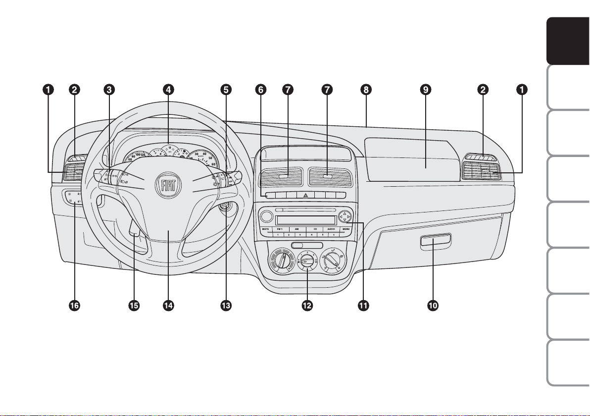
DASHBOARD
The presence and position of the controls, the instruments and the indicators may vary according to the versions.
1. Adjustable side air vents - 2. Fixed side air vents - 3. Left stalk: external lights control - 4. Instrument panel -
5. Right stalk: windscreen wiper controls, trip computer - 6. Controls on dashboard - 7. Adjustable central air vents - 8. Fixed up-
per air vent - 9. Front airbag - passenger side - 10. Oddment compartment - 11. Sound system (where provided) - 12. HVAC
controls - 13. Ignition device - 14. Front airbag - driver’s side - 15. Steering wheel adjustment lever - 16. Control panel: fog
lights/rear fog light/headlight position adjustment/digital display/multifunctional display.
F0R0001m
fig. 1
Page 7
6
SAFETY
DEVICES
CORRECT USE
OF THE
CAR
WARNING
LIGHTS AND
MESSAGES
IN AN
EMERGENCY
CAR
MAINTENANCE
TECHNICAL
SPECIFICATIONS
INDEX
DASHBOARD
AND CONTROLS
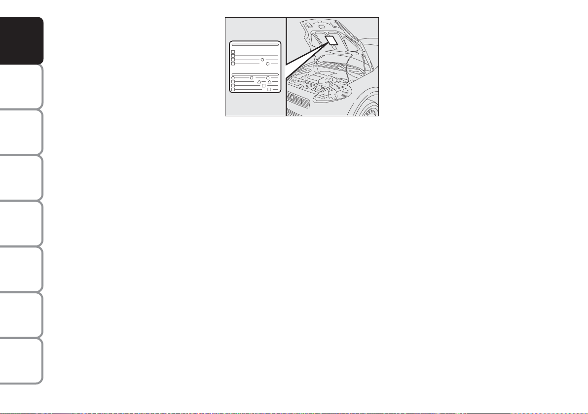
SYMBOLS
Special coloured labels have been attached
near or actually on some of the components of your car. These labels bear symbols that remind you of the precautions
to be taken as regards that particular component.
The plate summarising the symbols used
can be found under the bonnet fig. 1.
THE FIAT CODE SYSTEM
This is an electrical engine locking system
which increases protection from attempted theft of the car. It is automatically
activated when the ignition key is extracted.
Each key contains an electronic device
which modulates the signal emitted during ignition by an antenna incorporated in
the ignition device. This signal is the ‘password’ which changes at each ignition and
which the control unit uses to recognise
the key and allow ignition.
fig. 1
F0R0002m
Page 8
7
SAFETY
DEVICES
CORRECT USE
OF THE
CAR
WARNING
LIGHTS AND
MESSAGES
IN AN
EMERGENCY
CAR
MAINTENANCE
TECHNICAL
SPECIFICATIONS
INDEX
DASHBOARD
AND CONTROLS
In this case, turn the key to STOP and
then back to MAR; try with the other
keys provided if the problem persists.
Contact a Fiat Dealership if you still cannot start the engine.
IMPORTANT Each key has its own code
which must be stored by the system ECU.
Contact a Fiat Dealership to have new
keys (up to eight) stored.
Warning light
Y
coming on when driving
❒
If the warning light Yturns on, this
means that the system is running a selftest (for example for a voltage drop).
❒
If the warning light Ystays on, contact a Fiat Dealership.
The electronic components
inside the key may be damaged if the key is submitted to
sharp knocks.
OPERATION
Each time the car is started turning the ignition key to MAR, the Fiat CODE system control unit sends a recognition code
to the engine control unit to deactivate
the inhibitor.
The code is sent only if the Fiat CODE
system control unit has recognised the
code transmitted from the key.
Each time the ignition key is turned to
STOP, the Fiat CODE system deactivates
the functions of the engine electronic control unit.
If the code has not been recognised correctly, the warning light
Y
turns on accompanied by the related message on the
display (see section “Warning lights and
messages”).
Page 9
8
SAFETY
DEVICES
CORRECT USE
OF THE
CAR
WARNING
LIGHTS AND
MESSAGES
IN AN
EMERGENCY
CAR
MAINTENANCE
TECHNICAL
SPECIFICATIONS
INDEX
DASHBOARD
AND CONTROLS
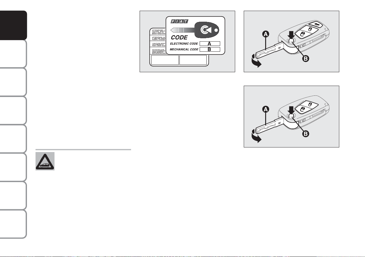
KEY WITH REMOTE CONTROL
fig. 3
The metal insert A is retractable and it operates:
❒
the ignition switch;
❒
the door locks;
❒
the fuel filler lock (where provided).
To extract the metal insert, press button
B.
THE KEYS
CODE CARD fig. 2
The car is delivered with two copies of the
ignition key and with the CODE card
which bears the following:
A the electronic code;
B the mechanical key code to be given
to the Fiat Dealership when ordering
duplicate keys.
Make sure you have the electronic code
A-fig. 2 with you at all times.
IMPORTANT In order to ensure perfect
efficiency of the electronic devices contained inside the keys, they should never
be exposed to direct sunlight.
All the keys and the CODE
card must be handed over to
the new owner when selling
the car.
fig. 2
F0R0003m
fig. 3
F0R0004m
fig. 4
F0R0005m
To refit it proceed as follows:
❒
keep button B pressed and move the
metal insert A;
❒
release button B and turn the metal insert A until hearing the proper locking click.
Page 10
9
SAFETY
DEVICES
CORRECT USE
OF THE
CAR
WARNING
LIGHTS AND
MESSAGES
IN AN
EMERGENCY
CAR
MAINTENANCE
TECHNICAL
SPECIFICATIONS
INDEX
DASHBOARD
AND CONTROLS
Button Ëis used for opening the doors
and the tailgate.
Button Áis used for locking the doors and
the tailgate.
Button
R
(present in some versions only) is used for remote opening of the tailgate.
The passenger’s compartment lights will
come on for a preset time when the doors
are unlocked.
Only press button B with the
key away from your body,
specifically from your eyes and from
objects which could get damaged (e.g.
your clothes). Do not leave the key
unattended to avoid the button from
being accidentally pressed while it is
being handled, e.g. by a child.
WARNING
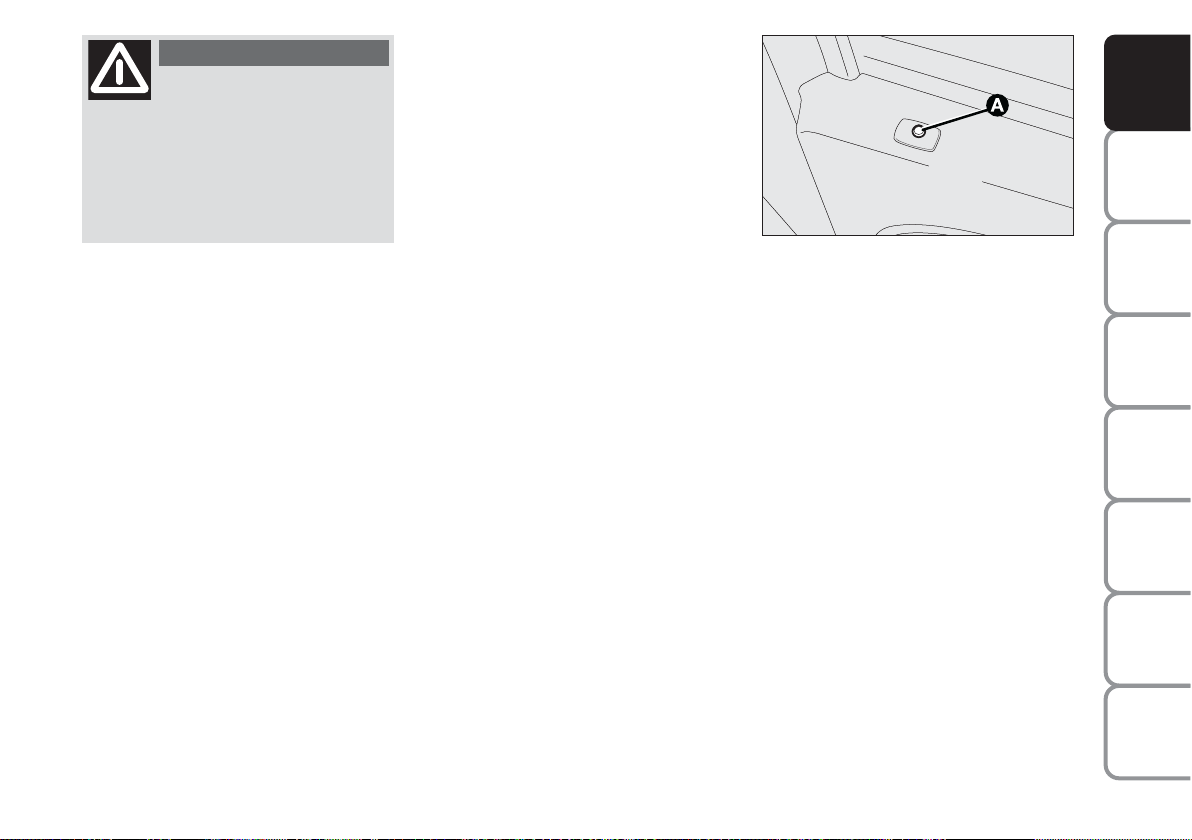
LED indications on the driver’s
door fig. 5
When locking the doors, led A switches
on for about 3 seconds and than starts
flashing (deterrence function).
If one or more doors or the tailgate are
not closed correctly when the doors are
locked, the led and direction indicators
start flashing quickly. The operation will
not be completed.
fig. 5
F0R0006m
Page 11
10
SAFETY
DEVICES
CORRECT USE
OF THE
CAR
WARNING
LIGHTS AND
MESSAGES
IN AN
EMERGENCY
CAR
MAINTENANCE
TECHNICAL
SPECIFICATIONS
INDEX
DASHBOARD
AND CONTROLS
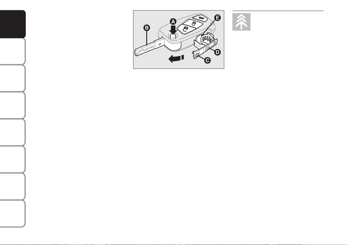
Replacing the battery of the key
with remote control fig. 6
Battery replacement:
❒
press button A and open the metal insert B;
❒
turn the screw C to :using a fine bit
screwdriver;
❒
take out the battery case D and replace
the battery E making sure that the bias
is correct;
❒
refit the battery case D inside the key
and lock it turning the screw C to
Á
Used batteries are harmful to
the environment. They should
be disposed of as specified by
law in the special containers
provided, or take them to a Fiat Dealership, which will deal with their disposal.
fig. 6
F0R0007m
Request for additional remote
controls
The system may recognise up to 8 remote
controls. Should a new remote control be
necessary, contact a Fiat Dealership, taking with you the CODE card, a personal
identity document and the car’s ownership documents.
Page 12
11
SAFETY
DEVICES
CORRECT USE
OF THE
CAR
WARNING
LIGHTS AND
MESSAGES
IN AN
EMERGENCY
CAR
MAINTENANCE
TECHNICAL
SPECIFICATIONS
INDEX
DASHBOARD
AND CONTROLS
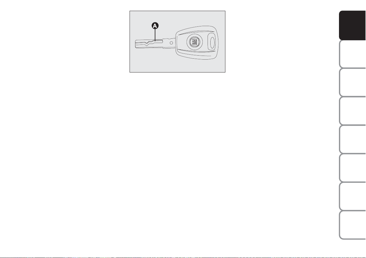
HEADLIGHT WASHER
(where provided) fig. 7
The metal insert of the key A is fixed.
The key operates:
❒
the ignition switch;
❒
the door locks;
❒
the fuel filler lock (where provided).
fig. 7
F0R0008m
ALARM
The car alarm system is available at Lineaccessori Fiat.
Page 13

12
SAFETY
DEVICES
CORRECT USE
OF THE
CAR
WARNING
LIGHTS AND
MESSAGES
IN AN
EMERGENCY
CAR
MAINTENANCE
TECHNICAL
SPECIFICATIONS
INDEX
DASHBOARD
AND CONTROLS
Type
Key without remote control
Key with remote control
Direction indicators
flashing (only with key
with remote control)
Deterrence led
The main functions that can be activated with the keys (with or without remote control) are the following:
Unlocking
the doors
Turn key anticlockwise
(driver’s side)
Turn key anticlockwise
(driver’s side)
Press briefly
Ë
blinks twice
Off
Locking the doors
from the outside
Turn key clockwise
(driver’s side)
Turn key clockwise
(driver’s side)
Briefly press
Á
blinks once
Steady for
approximately
3 seconds and then
deterrent blinking
Unlocking the
tailgate
–
–
Briefly press R
blinks twice
Deterrent
blinking
IMPORTANT The windows will be opened when the doors are unlocked; the windows will be closed when the doors are
locked.
Windows down
(where provided)
–
–
Hold pressed
Ë
(for longer than 2
seconds)
blinks twice
Off
Windows up
(where provided)
–
–
Hold pressed button
Á
(for longer than
seconds)
blinks once
Deterrence led
blinks
Page 14
13
SAFETY
DEVICES
CORRECT USE
OF THE
CAR
WARNING
LIGHTS AND
MESSAGES
IN AN
EMERGENCY
CAR
MAINTENANCE
TECHNICAL
SPECIFICATIONS
INDEX
DASHBOARD
AND CONTROLS
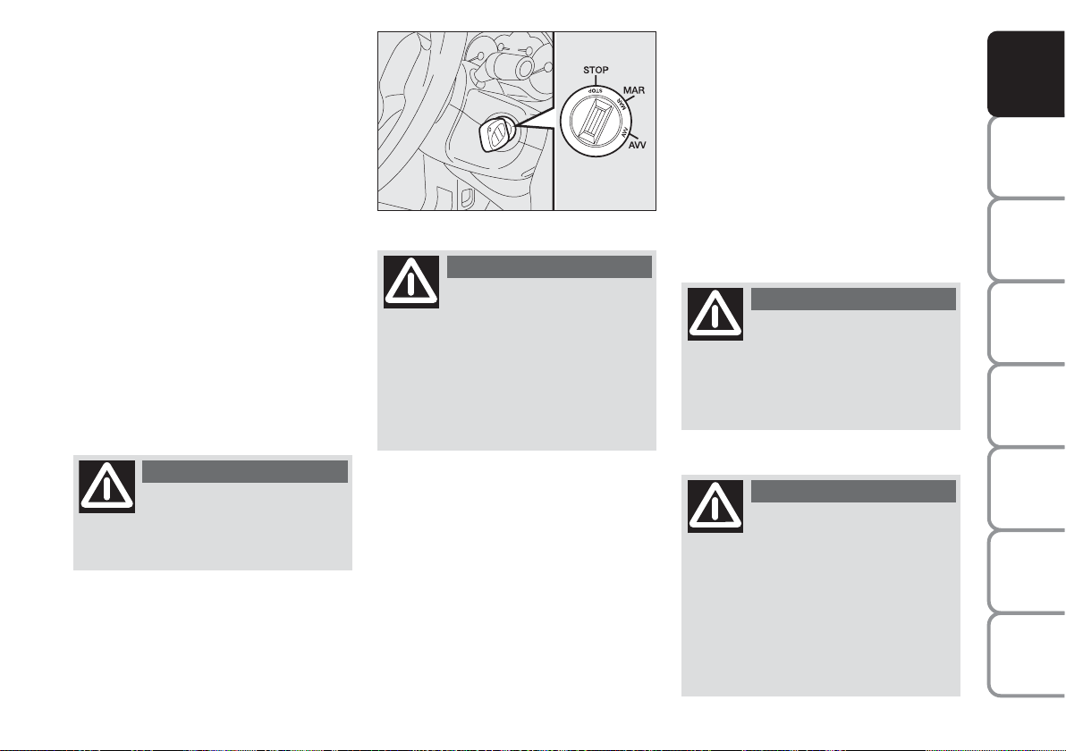
IGNITION
DEVICE
The key can be turned to 3 different positions fig. 8:
❒
STOP: engine off, key extractable,
steering locked. Some electrical devices
(e.g. sound system, central door locking system, etc.) may work.
❒
MAR: driving position. All electrical devices may work.
❒
AVV: engine starting (unstable position).
The ignition switch is fitted with an electronic safety system that, in the event the
engine is not started, turns back the ignition key to STOP before repeating the
starting operation.
STEERING COLUMN LOCK
Engaging
When the key is at STOP, remove the
key and turn the steering wheel until it
locks.
Disengaging
Rock the steering wheel slightly as you
turn the ignition key to MAR.
If the ignition device is tam-
pered with (e.g.: attempted
theft), have it checked over by a Fiat
Dealership as soon as possible.
WARNING
Always remove the key when
you leave your car to prevent someone from accidentally operating the controls. Remember to
apply the handbrake. Engage first
gear if the car is parked uphill or reverse if the car is parked downhill.
Never leave children unattended in
the car.
WARNING
fig. 8
F0R0009m
Never extract the key while
the vehicle is moving. The
steering wheel would be locked as
soon as the steering wheel is turned.
This also applies to when the car is
towed.
WARNING
It is absolutely forbidden to
carry out whatever aftermarket operation involving steering
system or steering column modifications (e.g.: installation of anti-theft
device) that could badly affect performance and safety, cause the lapse
of warranty and also result in noncompliance of the car with homologation requirements.
WARNING
Page 15
14
SAFETY
DEVICES
CORRECT USE
OF THE
CAR
WARNING
LIGHTS AND
MESSAGES
IN AN
EMERGENCY
CAR
MAINTENANCE
TECHNICAL
SPECIFICATIONS
INDEX
DASHBOARD
AND CONTROLS
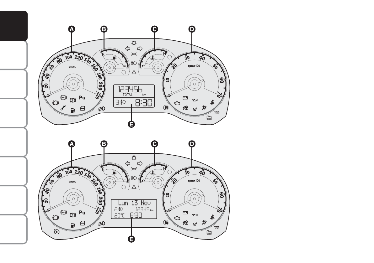
INSTRUMENT PANEL
Versions with digital display
A Speedometer (speed indicator)
B Fuel level gauge with reserve warning
light
C Engine coolant temperature gauge and
excessive temperature warning light
D Rev counter
E Digital display
Versions with multifunction display
A Speedometer (speed indicator)
B Fuel level gauge with reserve warning
light
C Engine coolant temperature gauge and
excessive temperature warning light
D Rev counter
E Multifunction display
F0R0010m
fig. 9
F0R0011m
fig. 10
Page 16
15
SAFETY
DEVICES
CORRECT USE
OF THE
CAR
WARNING
LIGHTS AND
MESSAGES
IN AN
EMERGENCY
CAR
MAINTENANCE
TECHNICAL
SPECIFICATIONS
INDEX
DASHBOARD
AND CONTROLS
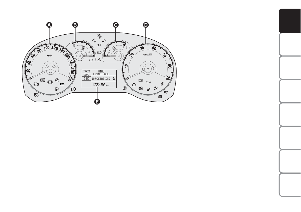
Versions with reconfigurable
multifunction display
A Speedometer (speed indicator)
B Fuel level gauge with reserve warning
light
C Engine coolant temperature gauge and
excessive temperature warning light
D Rev counter
E Reconfigurable multifunction display
F0R0215m
fig. 11
Page 17
16
SAFETY
DEVICES
CORRECT USE
OF THE
CAR
WARNING
LIGHTS AND
MESSAGES
IN AN
EMERGENCY
CAR
MAINTENANCE
TECHNICAL
SPECIFICATIONS
INDEX
DASHBOARD
AND CONTROLS
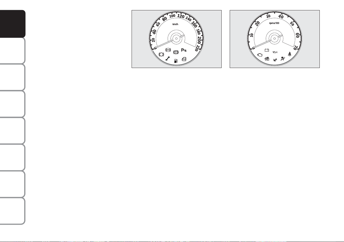
INSTRUMENTS
Instrument background colour and type
may vary according to the version.
SPEEDOMETER fig. 12
It shows the car speed.
REV. COUNTER fig. 13
Rev counter shows engine rpm.
IMPORTANT The electronic injection
control system gradually shuts off the flow
of fuel when the engine is ‘over-revving’
resulting in a gradual loss of engine power.
When the engine is idling, the rev counter
may indicate a gradual or sudden increase
of the speed.
This is normal and does not indicate a
fault. It may be caused, for example, by the
operation of the climate control system
or fan. In these case, a slow change in engine speed is used to protect the battery
charge.
fig. 12
F0R0012m
fig. 13
F0R0013m
Page 18
17
SAFETY
DEVICES
CORRECT USE
OF THE
CAR
WARNING
LIGHTS AND
MESSAGES
IN AN
EMERGENCY
CAR
MAINTENANCE
TECHNICAL
SPECIFICATIONS
INDEX
DASHBOARD
AND CONTROLS
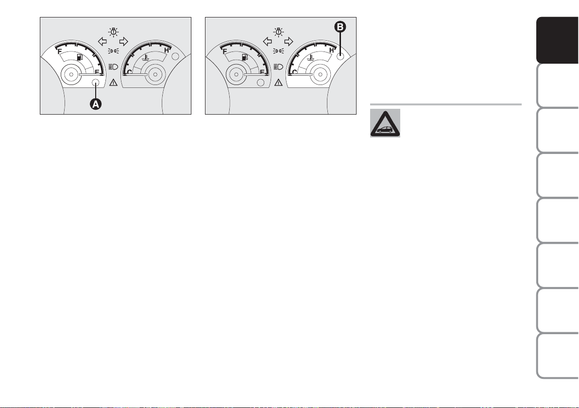
FUEL LEVEL GAUGE fig. 14
This shows the amount of fuel left in the
fuel tank.
E empty tank(see “At the filling station”).
F full tank.
The reserve warning light A turns on to
indicate that approximately 7 litres of fuel are left in the tank.
Do not travel with the tank nearly empty:
lack of fuel supply could damage the catalyser.
IMPORTANT The needle will point to E
and warning light A will blink to indicate a
fault in the system. Go to a Fiat Dealership to have the system checked.
ENGINE COOLANT
TEMPERATURE GAUGE fig. 15
This shows the temperature of the engine
coolant fluid and begins working when the
fluid temperature exceeds approx. 50°C.
Under normal conditions, the needle
should hover around the middle of the
scale according to the working conditions.
C Low engine coolant temperature.
H High engine coolant temperature.
Warning light B may light up (and a message on the multifunctional display may appear in certain versions) to indicate that
the coolant fluid temperature is too high;
in this case, stop the engine and contact
a Fiat Dealership.
fig. 14
F0R0014m
fig. 15
F0R0015m
If the needle reaches the red
area, stop the engine immediately and contact a Fiat
Dealership.
Page 19
18
SAFETY
DEVICES
CORRECT USE
OF THE
CAR
WARNING
LIGHTS AND
MESSAGES
IN AN
EMERGENCY
CAR
MAINTENANCE
TECHNICAL
SPECIFICATIONS
INDEX
DASHBOARD
AND CONTROLS
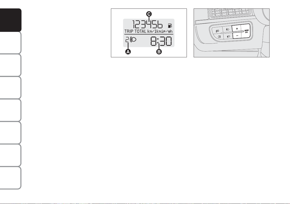
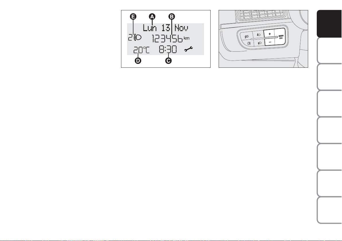
DIGITAL DISPLAY
STANDARD SCREEN fig. 16
The standard screen shows the following
indications:
A Headlight aiming position (only with
dipped beam headlights on).
B Clock (always displayed, even with ig-
nition key removed and front doors
closed).
C Odometer (distance covered in kilo-
metres or miles) and TRIP data.
Note With key removed (when opening
one of the front doors) the display will
turn on and show for a few seconds the
km or mi covered.
CONTROL BUTTONS fig. 17
+ To scroll the displayed menu and the
related options upwards or to increase the value displayed.
MENU
ESC
Press briefly to access the menu
and/or go to next screen or to
confirm the required menu option.
Hold pressed to go back to the
standard screen.
– To scroll the displayed menu and the
related options downwards or to decrease the displayed value.
Note Buttons + and – activate different
functions according to the following situations:
To adjust light inside the passenger
compartment
– standard screen, to adjust instrument
panel brightness, sound system, and automatic climate control system.
Setup menu
– to scroll the menu options upwards and
downwards;
– to increase or decrease values during settings.
fig. 16
F0R0016m
fig. 17
F0R0017m
Page 20

19
SAFETY
DEVICES
CORRECT USE
OF THE
CAR
WARNING
LIGHTS AND
MESSAGES
IN AN
EMERGENCY
CAR
MAINTENANCE
TECHNICAL
SPECIFICATIONS
INDEX
DASHBOARD
AND CONTROLS
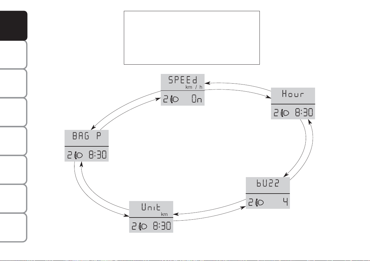
SETUP MENU fig. 18
The menu comprises a series of functions
arranged in a cycle which can be selected
through buttons + and – to access the dif-
ferent select operations and settings (setup) given in the following paragraphs.
The setup menu can be activated by pressing briefly button MENU ESC.
Single presses on buttons + and – will
scroll the setup menu options.
Handling modes differ with each other according to the characteristic of the option
selected.
Selecting a menu option
– press briefly button MENU ESC to select the menu option to set;
– press buttons + and – (by single presses) to select the new setting;
– press briefly button MENU ESC to
store the new setting and to go back to
the previously selected menu option.
Selecting “Set Clock”
– briefly press button MENU ESC to select the first value to change (hours);
– press buttons + and – (by single presses) to select the new setting;
– briefly press button MENU ESC to
store the new setting and to go to the
next setup menu option (minutes);
– after setting the values with the same
procedure, the system will go back to the
menu option previously selected.
Hold button MENU ESC pressed
– to quit the set up menu if you are in the
menu;
– to quit the displayed menu if you are setting an option;
– to save only the settings stored yet (and
confirmed by pressing button MENU
ESC).
The setup menu displaying is timed; when
quitting the menu due to timing expiry, only settings stored yet by the user (and confirmed by pressing briefly button MENU
ESC).
Page 21
20
SAFETY
DEVICES
CORRECT USE
OF THE
CAR
WARNING
LIGHTS AND
MESSAGES
IN AN
EMERGENCY
CAR
MAINTENANCE
TECHNICAL
SPECIFICATIONS
INDEX
DASHBOARD
AND CONTROLS
Briefly press button MENU ESC to start browsing
from the standard screen. Press + or – to browse with-
in the menu.
Note Only the short menu may be accessed for reasons of safety while the car is moving (“SPEEd” setting).
Stop the car to access the full menu.
fig. 18
F0R2003g
+
–
+
–
+
–
+
–
+
–
Page 22

21
SAFETY
DEVICES
CORRECT USE
OF THE
CAR
WARNING
LIGHTS AND
MESSAGES
IN AN
EMERGENCY
CAR
MAINTENANCE
TECHNICAL
SPECIFICATIONS
INDEX
DASHBOARD
AND CONTROLS
Setting the speed limit (SPEEd)
This function may be used to set the car
speed limit (km/h or mph), when this limit is exceeded the driver is immediately
alerted (see section “Warning lights and
messages”).
To set the speed limit, proceed as follows:
– briefly press button MENU ESC, the
message (SPEEd) and the previously set
unit (km/h) or (mph) will appear on the
display;
– press button + or – to activate (on) or
deactivate (OFF) the speed limit function;
– if the function is on, press buttons + or
– to select the required speed limit and
then press MENU ESC to confirm;
Note The speed may be set in the range
from 30 to 200 km/h, or from 20 to 125
mph according to the previously chosen
unit (see “Setting the distance unit”) described below. The setting will increase/decrease by five units each time
button +/– is pressed. Hold button +/–
pressed to increase/decrease the setting
rapidly. Complete the setting by briefly
pressing the button when you approach
the required setting.
– briefly press button MENU ESC to go
back to the menu screen or press the button for long to go back to the standard
screen without storing settings.To cancel
the setting, proceed as follows:
– briefly press button MENU ESC: (On)
will blink on the display;
– press button –: (Off) will blink on the
display;
– briefly press button MENU ESC to go
back to the menu screen or press the button for long to go back to the standard
screen without storing settings.
Setting the clock (Hour)
This function is used to set the clock.
Proceed as follows:
– briefly press button MENU ESC,
“hours” will flash on the display;
– press button + or – for setting;
– briefly press button MENU ESC, “min-
utes” will flash on the display;
– press button + or – for setting;
– briefly press button MENU ESC to go
back to the menu screen or press the button for long to go back to the standard
screen without storing settings.
Adjusting the buzzer volume
(bUZZ)
This function is used to adjust the buzzer
volume used for failure/warning indications and when MENU ESC, + and –
buttons are pressed.
To adjust the volume proceed as follows:
– briefly press button MENU ESC, the
display will show the wording (bUZZ);
– press button + or – to select the required volume (volume can be adjusted according to 8 levels).
– briefly press button MENU ESC to go
back to the menu screen or press the button for long to go back to the standard
screen without storing settings.
Page 23
22
SAFETY
DEVICES
CORRECT USE
OF THE
CAR
WARNING
LIGHTS AND
MESSAGES
IN AN
EMERGENCY
CAR
MAINTENANCE
TECHNICAL
SPECIFICATIONS
INDEX
DASHBOARD
AND CONTROLS
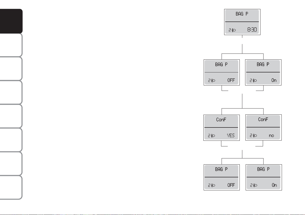
Front passenger’s airbag
and side bag
activation/deactivation
(where provided) (BAG P)
This function is used to activate/deactivate
the front passenger’s airbag.
Proceed as follows:
❒
press button MENU ESC and after
the message (BAG P OFF) (to deactivate) or (BAG P On) (to activate) is displayed by pressing buttons + or –, press
again button MENU ESC;
❒
the confirmation request message will
be displayed;
❒
press buttons + or – to select (YES)
(confirming activation/deactivation) or
(no) (to abort);
❒
briefly press button MENU ESC to
confirm setting e to go back to the
menu screen or press the button for
long to go back to the standard screen
without storing settings.
MENU ESC
MENU ESC
MENU ESC
–
+
–
+
–
+
–
+
F0R1001g
F0R1003g
F0R1002g
F0R1005i
F0R1006g
F0R1002g
F0R1003g
Setting the distance unit (Unit)
With this function it is possible to set the
unit.
To set the required unit proceed as follows:
– briefly press button MENU ESC, the
display will show the message (Unit) and
the previously set unit (km) or (mi);
– press button + or – to select the required distance unit.
– briefly press button MENU ESC to go
back to the menu screen or press the button for long to go back to the standard
screen without storing settings.
Page 24
23
SAFETY
DEVICES
CORRECT USE
OF THE
CAR
WARNING
LIGHTS AND
MESSAGES
IN AN
EMERGENCY
CAR
MAINTENANCE
TECHNICAL
SPECIFICATIONS
INDEX
DASHBOARD
AND CONTROLS
CONTROL BUTTONS fig. 21
+ To scroll the displayed menu and the
related options upwards or to increase the value displayed.
MENU
ESC
Press briefly to access the menu
and/or go to next screen or to
confirm the required menu option.
Hold pressed to go back to the
standard screen.
– To scroll the displayed menu and the
related options downwards or to decrease the value displayed.
MULTIFUNCTION
DISPLAY
(where provided)
The car can be equipped with the multifunctional display that, according to the
settings made, will show useful information necessary when driving.
“STANDARD” SCREEN fig. 20
The standard screen shows the following
information:
A Date.
B Odometer (covered km or miles).
C Clock (always displayed, even with ig-
nition key removed and front doors
closed).
D External temperature.
E Headlight aiming position (only with
dipped beam headlights on).
Note When opening one of the front
doors, the display will turn on and show
for a few seconds the clock and the kilometres or miles covered.
fig. 20
F0R0018m
Note Buttons + and – activate different
functions according to the following situations:
To adjust light inside the passenger
compartment
– standard screen, to adjust instrument
panel brightness, sound system, and automatic climate control system.
Setup menu
– to scroll the menu options upwards and
downwards;
– to increase or decrease values during settings.
fig. 21
F0R0019m
Page 25

24
SAFETY
DEVICES
CORRECT USE
OF THE
CAR
WARNING
LIGHTS AND
MESSAGES
IN AN
EMERGENCY
CAR
MAINTENANCE
TECHNICAL
SPECIFICATIONS
INDEX
DASHBOARD
AND CONTROLS
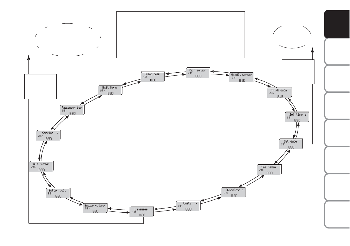
SETUP MENU fig. 22
The menu comprises a series of functions
arranged in a cycle which can be selected
through buttons + and – to access the dif-
ferent select operations and settings (setup) given in the following paragraphs. A
submenu is provided for some items
(Clock and Unit setting).
The setup menu can be activated by pressing briefly button MENU ESC.
Single presses on buttons + or – will scroll
the setup menu options.
Handling modes differ with each other according to the characteristic of the option
selected.
Selecting an option of the main menu without submenu
– press briefly button MENU ESC to select the main menu option to set;
– press buttons + or – (by single presses) to select the new setting;
– press briefly button MENU ESC to
store the new setting and to go back to
the main menu option previously selected.
Selecting “Set Date” and
“Set time”:
– briefly press button MENU ESC to select the first value to change (e.g. hours
/minutes or year / month / day);
– press buttons + or – (by single presses) to select the new setting;
– briefly press button MENU ESC to store
the new setting and to go to the next setup menu option, if this is the last one you
will go back to the previously selected option of the main menu.
Hold button MENU ESC pressed:
– to quit the set-up menu if you are in the
main menu;
– to quit the main menu if you are at another point of the menu (e.g.: at submenu
option setting level, at submenu level or
at main menu option setting level);
– to save only the settings stored yet (and
confirmed by pressing button MENU
ESC).
The setup menu environment is timed.
Only the changes saved by the user b
briefly pressing MENU ESC will be saved
when the menu is automatically closed.
Selecting an option of the main menu with
submenu:
– briefly press button MENU ESC to display the first submenu option;
– press buttons + or – (by single presses) to scroll all the submenu options;
– press briefly button MENU ESC to select the displayed submenu option and to
open the relevant setup menu;
– press buttons + or – (by single presses) to select the new setting for this submenu option;
– briefly press button MENU ESC to
store the new setting and to go back to
the previously selected submenu option.
Page 26
25
SAFETY
DEVICES
CORRECT USE
OF THE
CAR
WARNING
LIGHTS AND
MESSAGES
IN AN
EMERGENCY
CAR
MAINTENANCE
TECHNICAL
SPECIFICATIONS
INDEX
DASHBOARD
AND CONTROLS
Day
Year Month
Türk
Nederlands
Español
Português
Français
Italiano
Deutsch Polski
English
Example:
fig. 21
Example:
Briefly press MENU ESC on the standard screen to
browse. Press + or – to browse within the menu.
Note Only the short menu may be accessed for reasons of safety while the car is moving (“Speed Beep”
setting). Stop the car to access the full menu.
F0R2004g
ESC
MENU
briefly press
+
–
EXIT MENU
SPEED BEEP
RAIN SENSOR
(where provided )
SET TIME
SET DATE
SEE RADIO
AUTOCLOSE
UNIT UNIT
LANGUAGE
WARNING VOLUME
BUTTON VOLUME
BELT BUZZER (*)
SERVICE
PASSENGER BAG
(*) This function may only be displayed after the SBR system is deactivated by a Fiat Dealership.
TRIP B DATA
ESC
MENU
briefly press
HEADLIGHTS
SENSOR
(where provided)
+
–
+
–
+
–
+
–
+
–
+
–
+
–
+
–
+
–
+
–
+
–
+
–
+
–
+
–
+
–
Page 27

26
SAFETY
DEVICES
CORRECT USE
OF THE
CAR
WARNING
LIGHTS AND
MESSAGES
IN AN
EMERGENCY
CAR
MAINTENANCE
TECHNICAL
SPECIFICATIONS
INDEX
DASHBOARD
AND CONTROLS
– press button –: (Off) will flash on the display;
– briefly press button MENU ESC to go
back to the menu screen or press the button for long to go back to the standard
screen without storing settings.
Rain sensor sensitivity adjustment
(Rain sensor) (where provided)
With this function it is possible to adjust
the rain sensor sensitivity according to 4
levels.
To set the required sensitivity level proceed as follows:
– briefly press button MENU ESC, the
previously set sensitivity “level” will flash
on the display;
– press button + or – for setting;
– briefly press button MENU ESC to go
back to the menu screen or press the button for long to go back to the standard
screen without storing settings.
Speed limit (Speed Beep)
This function may be used to set the car
speed limit (km/h or mph); when this limit is exceeded the driver is immediately
alerted (see section “Warning lights and
messages”).
To set the speed limit, proceed as follows:
– briefly press button MENU ESC, the
display will show the wording (Speed
Buzz);
– press button + or – to select speed lim-
it activation (On) or deactivation (Off);
– if the function has been activated (On),
press buttons + or – to select the required speed limit and then press MENU
ESC to confirm.
Note The speed may be set in the range
from 30 to 200 km/h, or from 20 to 125 mph
according to the previously chosen unit (see
“Setting the distance unit”) described below.
The setting will increase/decrease by five
units each time button +/– is pressed. Hold
button +/– pressed to increase/decrease the
setting rapidly. Complete the setting by
briefly pressing the button when you approach the required setting.
– briefly press button MENU ESC to go
back to the menu screen or press the button for long to go back to the standard
screen without storing settings.
To cancel the setting, proceed as follows:
– briefly press button MENU ESC: (On)
will blink on the display;
Headlight sensor
(Automatic headlight sensor
sensitivity adjustment)
(where provided)
This function is used to adjust the
dusk sensor sensitivity to three levels
(level 1 = minimum, level 2 = medium, level 3 = maximum); higher the sensitivity,
lower the quantity of external light needed to switch the headlights on.
Proceed as follows to set:
– briefly press button MENU ESC, the
previously set level will flash on the display;
– press button + or – for setting;
– briefly press button MENU ESC to go
back to the menu screen or press the button for long to go back to the standard
screen without storing settings.
Page 28

27
SAFETY
DEVICES
CORRECT USE
OF THE
CAR
WARNING
LIGHTS AND
MESSAGES
IN AN
EMERGENCY
CAR
MAINTENANCE
TECHNICAL
SPECIFICATIONS
INDEX
DASHBOARD
AND CONTROLS
Trip B On/Off (tripB data)
Through this option it is possible to activate (On) or deactivate (Off) the Trip B
(partial trip).
For further information see “Trip computer”.
Proceed as follows to switch the function
on and off:
– briefly press button MENU ESC: (On)
or (Off) will flash on the display (according to previous setting);
– press button + or – for setting;
– briefly press button MENU ESC to go
back to the menu screen or press the button for long to go back to the standard
screen without storing settings.
Setting the clock (Set time)
This function allows to set the clock through
two sub-menus: “Time” and “Mode”.
Proceed as follows:
– briefly press button MENU ESC, the
display will show the two sub-menus
“Time” and “Mode”;
– press button + or – to surf the two submenus;
– select the required option and then
press button MENU ESCbriefly;
– when accessing the “Hour” submenu: –
briefly press button MENU ESC,
“hours” will flash on the display;
– press button + or – for setting;
– briefly press button MENU ESC, “min-
utes” will flash on the display;
– press button + or – for setting;
– when accessing the “Format” submenu:
briefly press button MENU ESC : the
previously set display format will flash on
the display;
– press button + or – to select “24h” or
“12h”.
When you have made the required settings, briefly press button MENU ESC
to go back to the menu screen or press
the button for long to go back to the standard screen without storing settings.
– hold MENU ESC pressed to go back
to the standard screen or main menu according to the points of the menu where
you are at.
Set date (Set Date)
This function may be used to update the
date (year - month - day).
To correct the date proceed as follows:
– briefly press button MENU ESC: “day”
will flash on the display;
– press button + or – for setting;
– briefly press button MENU ESC:
“month” will flash on the display;
– press button + or – for setting;
– briefly press button MENU ESC
:
“year” will flash on the display;
– press button + or – for setting.
Note The setting will increase or de-
crease by one unit each time + or – is
pressed. Hold the button pressed to increase/decrease the setting rapidly. Complete the setting by briefly pressing the
button when you approach the required
setting.
– briefly press button MENU ESC to go
back to the menu screen or press the button for long to go back to the standard
screen without storing settings.
Page 29

28
SAFETY
DEVICES
CORRECT USE
OF THE
CAR
WARNING
LIGHTS AND
MESSAGES
IN AN
EMERGENCY
CAR
MAINTENANCE
TECHNICAL
SPECIFICATIONS
INDEX
DASHBOARD
AND CONTROLS
Automatic door locking
with car
running (Autoclose)
When activated (On), this function locks
automatically the doors when the car
speed exceeds 20 km/h.
This function is available on all versions
and may only be switched off by means
of the multifunctional display or reconfigurable multifunctional display.
To activate (On) or to deactivate (Off) this
function proceed as follows:
– briefly press button MENU ESC to display the three sub-menus;
– briefly press button MENU ESC: (On)
or (Off) will flash on the display (according to previous setting);
– press button + or – for setting;
– briefly press button MENU ESC to
go back to the menu screen or press the
button for long to go back to the standard screen without storing settings.
– hold MENU ESC pressed to go back
to the standard screen or main menu according to the points of the menu where
you are at.
Audio repetition (See radio)
With this function the display repeats information relevant to the sound system.
– Radio: tuned radio station frequency or
RDS message, automatic tuning activation
or AutoSTore;
– CD audio, CD MP3: track number;
– CD Changer: CD number and track
number;
To activate (On) or to deactivate (Off)
sound system info displaying proceed as
follows:
– briefly press MENU ESC: (On) or (Off)
will flash on the display (according to previous setting);
– press button + or – for setting;
– briefly press button MENU ESC to go
back to the menu screen or press the button for long to go back to the standard
screen without storing settings.
Set units (Unit of measure)
With this function it is possible to set the
units through three sub-menus: “Distances”,
“Consumption” and “Temperature”.
Proceed as follows to set the required unit:
– briefly press button MENU ESC to display the three sub-menus;
– press button + or – to surf the three submenus;
– select the required sub-menu and then
press briefly button MENU ESC;
– when accessing the “Distances”submenu:
briefly press MENU ESC: either “km” or
“mi” will appear on the display (according
to the previous setting);
– press + or – to make your choice;
Page 30

29
SAFETY
DEVICES
CORRECT USE
OF THE
CAR
WARNING
LIGHTS AND
MESSAGES
IN AN
EMERGENCY
CAR
MAINTENANCE
TECHNICAL
SPECIFICATIONS
INDEX
DASHBOARD
AND CONTROLS
Selecting the language (Language)
The messages may be displayed in the following languages: Italian, Turkish, Dutch,
Portuguese, Polish, French, Spanish, English, German.
To set the required language proceed as
follows:
– briefly press button MENU ESC: the
previously set “language” “ will flash on the
display;
– press button + or – for setting;
– briefly press button MENU ESC to go
back to the menu screen or press the button for long to go back to the standard
screen without storing settings.
– when you are in the “Consumption” submenu: briefly press MENU ESC: either
“km/l” or “mpg” will appear on the display
(according to the previous setting);
If the distance unit set is “km” the fuel consumption unit will be displayed in km.
If the distance unit set is “mi” the fuel consumption unit will be displayed in “mpg”.
– press button + or – for setting;
– when accessing the “Temperature”submenu: briefly press MENU ESC: either
“°C” or “°F” will appear on the display (according to the previous setting);
– press button + or – for setting;
When you have made the required set-
tings, briefly press button MENU ESC to
go back to the menu screen or press the
button for long to go back to the standard
screen without storing settings.
– hold MENU ESC pressed to go back
to the standard screen or main menu according to the points of the menu where
you are at.
Adjusting the failure/warning
buzzer volume (Buzzer Volume)
With this function the volume of the
buzzer accompanying any failure/warning
indication can be adjusted according to 8
levels.
To adjust the volume proceed as follows:
– briefly press button MENU ESC: the
previously set volume “level” will flash on
the display;
– press button + or – for setting;
– briefly press button MENU ESC to go
back to the menu screen or press the button for long to go back to the standard
screen without storing settings.
Page 31

30
SAFETY
DEVICES
CORRECT USE
OF THE
CAR
WARNING
LIGHTS AND
MESSAGES
IN AN
EMERGENCY
CAR
MAINTENANCE
TECHNICAL
SPECIFICATIONS
INDEX
DASHBOARD
AND CONTROLS
Scheduled Servicing (Service)
Through this function it is possible to display information connected to proper car
servicing.
Proceed as follows:
– briefly press button MENU ESC: service in km or mi, according to previous
setting, will be displayed (see paragraph
“Units”);
– briefly press button MENU ESC to go
back to the menu screen or press the button for long to go back to the standard
screen.
Note The “Service Schedule” requires the
car to be serviced every 30,000 km (or
18,000 mi) or every 20,000 km (where
provided); this indication will appear automatically with the key at MAR when
there are 2000 km left (or 1240 mi) and
will be presented automatically every 200
km (or 124 mi). The indications will appear more frequently where there are 200
km left. The indication will appear in kilometres or miles according to the settings.
When the next scheduled service operation is approaching, the message “Service”
will appear on the display followed by the
number of kilometres or miles left when
the key is turned to MAR. Go to a Fiat
Dealership where the “Scheduled Service”
operations will be performed and the message will be reset.
Adjusting the button volume
(Button Vol.)
This function may be used to adjust the
volume of the beep accompanying the activation of buttons MENU ESC, + and
– can be adjusted according to 8 levels.
To adjust the volume proceed as follows:
– briefly press button MENU ESC: the
previously set volume “level” will flash on
the display;
– press button + or – for setting;
– briefly press button MENU ESC to go
back to the menu screen or press the button for long to go back to the standard
screen without storing settings.
Page 32

31
SAFETY
DEVICES
CORRECT USE
OF THE
CAR
WARNING
LIGHTS AND
MESSAGES
IN AN
EMERGENCY
CAR
MAINTENANCE
TECHNICAL
SPECIFICATIONS
INDEX
DASHBOARD
AND CONTROLS
Passenger front and side airbag
activation/deactivation
(where provided) (passenger bag)
This function shall be used to activate/deactivate the front passenger’s airbag.
Proceed as follows:
❒
press button MENU ESC and press
MENU ESC again after the message
(Bag pass: Off) (to deactivate) or (Bag
pass: On) (to activate) is displayed by
pressing buttons + and –;
❒
display will show the confirmation message;
❒
press buttons + or – to select (Yes)
(confirming activation/deactivation) or
(No) (to abort);
❒
briefly press button MENU ESC to
confirm setting e to go back to the
menu screen or press the button for
long to go back to the standard screen
without storing settings.
MENU ESC
MENU ESC
MENU ESC
–
+
–
+
–
+
–
+
–
+
–
+
F0R1009g
F0R1011g
F0R1010g
F0R1013g
F0R1014g
F0R1009g
F0R1009g
MENU ESC
F0R1015g
F0R1016g
Exit Menu
This is the last function that closes the circular setting cycle listed in the initial menu
screen.
Briefly press button MENU ESC to go
back to the standard screen without storing settings.
Press button – to return to the first menu
option (Speed Beep).
Page 33

32
SAFETY
DEVICES
CORRECT USE
OF THE
CAR
WARNING
LIGHTS AND
MESSAGES
IN AN
EMERGENCY
CAR
MAINTENANCE
TECHNICAL
SPECIFICATIONS
INDEX
DASHBOARD
AND CONTROLS
RECONFIGURABLE
MULTIFUNCTION
DISPLAY
(where provided)
The car may be equipped with reconfigurable a multifunctional display that, according to the settings made, will show
useful driving information.
“STANDARD” SCREEN fig. 23/a
The standard screen shows the following
information:
A Time
B Date
C Sport driving mode indication (where
provided)
D Odometer (distance travelled in kilo-
metres/miles)
E Car conditions (e.g. doors open, ice on
road, etc.)
F Headlight aiming position (with dipped
beam headlights on only)
G Outside temperature
When rotating the ignition key to MAR
position, the display shows, as main
screen, the indication of the date fig.23/a
or the overpressure of the turbo-charger fig.23/b according to the previous selection in the menu item “First screen”
(“Date” or “Engine Info”).
CONTROL BUTTONS fig. 24
+ To scroll the displayed menu and the
related options upwards or to increase the displayed value.
MENU Press briefly to access the menu
ESC and/or go to next screen or to
confirm the required menu option.
Long press to go back to the
standard screen.
– To scroll the displayed menu and the
related options downwards or to decrease the value displayed.
Note Buttons + and – activate different
functions according to the following situations:
– to scroll the menu options upwards and
downwards;
– to increase or decrease values during
settings.
Note When opening one of the front
doors, the display will turn on and show
for a few seconds the clock and the km or
mi covered.
fig. 24
F0R0019m
fig. 23/a
F0R2010g
fig. 23/b
F0R0241m
Page 34

33
SAFETY
DEVICES
CORRECT USE
OF THE
CAR
WARNING
LIGHTS AND
MESSAGES
IN AN
EMERGENCY
CAR
MAINTENANCE
TECHNICAL
SPECIFICATIONS
INDEX
DASHBOARD
AND CONTROLS
SETUP MENU fig. 25
The menu comprises a series of functions
arranged in a “circular fashion” which can
be selected through buttons + and – to
access the different select operations and
settings (setup) given in the following paragraphs. A submenu is provided for some
items (Clock and Unit setting).
The setup menu can be activated by pressing briefly button MENU ESC.
Single presses on buttons + or – will scroll
the setup menu options. Management
modes differ with each other according to
the characteristic of the option selected.
Selecting an option of the main menu
without submenu
– press briefly button MENU ESC to select the main menu option to set;
– press buttons + or – (by single presses) to select the new setting;
– press briefly button MENU ESC to
store the new setting and to go back to
the main menu option previously selected.
Selecting an option of the main menu with
submenu:
– press briefly button MENU ESC to display the first submenu option;
– press buttons + or – (by single presses) to scroll all the submenu options;
– press briefly button MENU ESC to select the displayed submenu option and to
open the relevant setup menu;
– press buttons + or – (by single presses) to select the new setting for this submenu option;
– press briefly button MENU ESC to
store the new setting and to go back to
the previously selected submenu option.
Page 35

34
SAFETY
DEVICES
CORRECT USE
OF THE
CAR
WARNING
LIGHTS AND
MESSAGES
IN AN
EMERGENCY
CAR
MAINTENANCE
TECHNICAL
SPECIFICATIONS
INDEX
DASHBOARD
AND CONTROLS
Example:
Day
Year Month
Türk
Nederlands
Español
Português
Français
Polski
Italiano
Deutsch
BELT BUZZER
RAIN SENSOR
(where provided)
TRIP B DATA
SET DATE
FIRST PAGE
SEE RADIO
AUTOCLOSE
UNIT
LANGUAGE
BUZZER VOL.
BUTTON VOL.
MENU ESC
briefly press
MENU ESC
briefly press
fig. 25
SERVICE
F0R2005g
SET TIME
SPEED BEEP
EXIT MENU
PASSENGER BAG
English
On the standard screen, briefly press MENU ESC to start browsing. Press + or – to browse within the menu. Note Only the short
menu may be accessed for reasons of safety while the car is moving
(“Brightness” and “Speed Beep”). Stop the car to access the full menu.
HEADLIGHT
SENSOR
(where provided)
–
+
+
+
+
+
+
+
+
+
+
+
+
+
+
+
+
+
–
–
–
–
–
–
–
–
–
–
–
–
–
–
–
–
Page 36

35
SAFETY
DEVICES
CORRECT USE
OF THE
CAR
WARNING
LIGHTS AND
MESSAGES
IN AN
EMERGENCY
CAR
MAINTENANCE
TECHNICAL
SPECIFICATIONS
INDEX
DASHBOARD
AND CONTROLS
Note The speed may be set in the range
from 30 to 200 km/h, or from 20 to 125
mph according to the previously chosen
unit (see “Setting the distance unit”) described below. The setting will increase/decrease by five units each time
button +/– is pressed. Hold button +/–
pressed to increase/decrease the setting
rapidly. Complete the setting by briefly
pressing the button when you approach
the required setting.
– briefly press button MENU ESC to go
back to the menu screen or press the button for long to go back to the standard
screen without storing settings.
To cancel the setting, proceed as follows:
– briefly press button MENU ESC: (On)
will blink on the display;
– press button –: (Off) will flash on the display;
– briefly press button MENU ESC to go
back to the menu screen or press the button for long to go back to the standard
screen without storing settings.
Speed beep (Speed limit)
This function is used to set the car speed
limit (km/h or mph); when this limit is exceeded the driver is immediately alerted
(see section “Warning lights and messages”).
To set the speed limit, proceed as follows:
– briefly press button MENU ESC, the
display will show the wording (Speed
Buzz);
– press button + or – to select speed lim-
it activation (On) or deactivation (Off);
– if the function has been activated (On),
press buttons + or – to select the required speed limit and then press MENU
ESC to confirm.
Page 37

36
SAFETY
DEVICES
CORRECT USE
OF THE
CAR
WARNING
LIGHTS AND
MESSAGES
IN AN
EMERGENCY
CAR
MAINTENANCE
TECHNICAL
SPECIFICATIONS
INDEX
DASHBOARD
AND CONTROLS
Rain sensor sensitivity adjustment
(Rain sensor) (where provided)
With this function it is possible to adjust
the rain sensor sensitivity according to 4
levels.
To set the required sensitivity level proceed as follows:
– briefly press button MENU ESC, the
previously set sensitivity “level” will flash
on the display;
– press button + or – for setting;
– briefly press button MENU ESC to go
back to the menu screen or press the button for long to go back to the standard
screen without storing settings.
Headlight sensor
(Automatic headlight sensor
sensitivity adjustment)
(where provided)
This function is used to adjust the dusk
sensor sensitivity to three levels (level 1
= minimum, level 2 = medium, level 3 =
maximum); higher the sensitivity, lower
the quantity of external light needed to
switch the headlights on.
Proceed as follows to set:
– briefly press button MENU ESC, the
previously set level will flash on the display;
– press button + or – for setting;
– briefly press button MENU ESC to go
back to the menu screen or press the button for long to go back to the standard
screen without storing settings.
Trip B data (Trip B on)
This function may be used to activate (On)
or deactivate (Off) the Trip B (partial trip).
For further information see “Trip computer”.
Proceed as follows to switch the function
on and off:
– briefly press button MENU ESC: (On)
or (Off) will flash on the display (according to previous setting);
– press button + or – for setting;
– briefly press button MENU ESC to go
back to the menu screen or press the button for long to go back to the standard
screen without storing settings.
Setting the time (Clock)
This function allows to set the clock
through two sub-menus: “Time” and
“Mode”.
Proceed as follows:
– briefly press button MENU ESC, the
display will show the two submenus
“Time” and “Mode”;
– press button + or – to switch between
the two submenus;
– select the required option and then
press button MENU ESCbriefly;
- when accessing the “Time” submenu: –
briefly press button MENU ESC,
“hours” will flash on the display;
– press button + or – for setting;
– briefly press button MENU ESC, “min-
utes” will flash on the display;
– press button + or – for setting.
Page 38

37
SAFETY
DEVICES
CORRECT USE
OF THE
CAR
WARNING
LIGHTS AND
MESSAGES
IN AN
EMERGENCY
CAR
MAINTENANCE
TECHNICAL
SPECIFICATIONS
INDEX
DASHBOARD
AND CONTROLS
Note The setting will increase or decrease by one unit each time + or – is
pressed. Hold the button pressed to increase/decrease the setting rapidly. Complete the setting by briefly pressing the
button when you approach the required
setting.
– when accessing the “Format” submenu:
briefly press button MENU ESC: the
previously set display format will flash on
the display;
– press button + or – to select “24h” or
“12h”.
When you have made the required settings, briefly press button MENU ESC to
go back to the menu screen or press the
button for long to go back to the standard
screen without storing settings.
– hold MENU ESC pressed to go back
to the standard screen or main menu according to the points of the menu where
you are at.
Set date (Set Date)
This function may be used to update the
date (year - month - day).
To correct the date proceed as follows:
– briefly press button MENU ESC:
“year” will flash on the display;
– press button + or – for setting;
– briefly press button MENU ESC:
“month” will flash on the display;
– press button + or – for setting;
– briefly press button MENU ESC: “day”
will flash on the display;
– press button + or – for setting.
Note The setting will increase or decrease by one unit each time + or – is
pressed. Hold the button pressed to increase/decrease the setting rapidly. Complete the setting by briefly pressing the
button when you approach the required
setting.
– briefly press button MENU ESC to go
back to the menu screen or press the button for long to go back to the standard
screen without storing settings.
First screen (information displayed
in the main screen)
(where provided)
This function enables to select the type of
information displayed in the main screen.
It is possible to display the date or the
pressure of the turbo-compressor.
To select one of the two items, proceed
as follows:
– push the button MENU ESC for a
short time, “First screen” is displayed;
– press again the button MENU ESC for
a short time to display the “Date” and
“Engine Info” options;
– press + or – to select the type of information to be displayed in the main screen;
– press MENU ESC for a short time to
store the selection and return to the previous screen or press the button for a
longer time to return to the standard
screen without storing the selection.
Rotating the ignition key on MAR, the reconfigurable multifunctional display, after
the start-up check, displays the previously set information using the “First screen”
function of the menu.
Page 39

38
SAFETY
DEVICES
CORRECT USE
OF THE
CAR
WARNING
LIGHTS AND
MESSAGES
IN AN
EMERGENCY
CAR
MAINTENANCE
TECHNICAL
SPECIFICATIONS
INDEX
DASHBOARD
AND CONTROLS
See radio
(Repeat audio information)
This function is used to display information relevant to the sound system.
– Radio: tuned radio station frequency or
RDS message, automatic tuning activation
or AutoSTore;
– CD audio, CD MP3: track number;
– CD Changer: CD number and track
number;
To activate (On) or to deactivate (Off)
sound system info displaying proceed as
follows:
– briefly press button MENU ESC: (On)
or (Off) will flash on the display (according to previous setting);
– press button + or – for setting;
– briefly press button MENU ESC to go
back to the menu screen or press the button for long to go back to the standard
screen without storing settings.
Autoclose
(Automatic door lock operation
with car running)
When activated (On), this function locks
automatically the doors when the car
speed exceeds 20 km/h.
This function is available on all versions
and may only be switched off by means
of the multifunctional display or reconfigurable multifunctional display.
Proceed as follows to switch this function
on or off:
- briefly press button MENU ESC to display a submenu;
– briefly press button MENU ESC: (On)
or (Off) will flash on the display (according to previous setting);
– press button + or – for setting;
– briefly press button MENU ESC to go
back to the menu screen or press the button for long to go back to the standard
screen without storing settings.
– hold MENU ESC pressed to go back to
the standard screen or main menu according to the points of the menu where you are
at.
Unit of measure (Set units)
This function may be used to set the unit
for measure in three submenus: “Distances”, “Consumption” and “Temperature”.
Proceed as follows to set the required
unit:
– briefly press button MENU ESC to display the three sub-menus;
– press button + or – to browse the three
submenus;
– select the required submenu and then
press briefly buttonMENU ESC;
– when accessing the “Distance” submenu:
briefly press MENU ESC: either “km” or
“mi” will appear on the display (according to the previous setting);
– press button + or – for setting;
– when accessing the “Consumption” submenu: briefly press MENU ESC: either
“km/l ”, “l/100km” or “mpg” will appear
on the display (according to the previous
setting);
If the distance unit set is “km” the fuel consumption unit will be displayed in km/l or
l/100km.
Page 40

39
SAFETY
DEVICES
CORRECT USE
OF THE
CAR
WARNING
LIGHTS AND
MESSAGES
IN AN
EMERGENCY
CAR
MAINTENANCE
TECHNICAL
SPECIFICATIONS
INDEX
DASHBOARD
AND CONTROLS
If the distance unit set is “mi” the fuel consumption unit will be displayed in “mpg”.
– press button + or – for setting;
– when accessing the “Temperature” submenu: briefly press MENU ESC: either
“°C” or “°F” will appear on the display according to the previous setting;
– press button + or – for setting;
When you have made the required settings, briefly press button MENU ESC to
go back to the menu screen or press the
button for long to go back to the standard
screen without storing settings.
– hold MENU ESC pressed to go back
to the standard screen or main menu according to the points of the menu where
you are at.
Language (Selecting the language)
The messages may be displayed in the following languages: Italian, German,
English, Spanish, French, Portuguese,
Dutch.
To set the required language proceed as
follows:
– briefly press button MENU ESC: the
previously set “language” “ will flash on the
display;
– press button + or – for setting;
– briefly press button MENU ESC to go
back to the menu screen or press the button for long to go back to the standard
screen without storing settings.
Buzzer volume (Adjusting the
failure/warning buzzer volume)
With this function the volume of the
buzzer accompanying any failure/warning
indication can be adjusted according to 8
levels.
To adjust the volume proceed as follows:
– briefly press button MENU ESC: the
previously set volume “level” will flash on
the display;
– press button + or – for setting;
– briefly press button MENU ESC to go
back to the menu screen or press the button for long to go back to the standard
screen without storing settings.
Page 41

40
SAFETY
DEVICES
CORRECT USE
OF THE
CAR
WARNING
LIGHTS AND
MESSAGES
IN AN
EMERGENCY
CAR
MAINTENANCE
TECHNICAL
SPECIFICATIONS
INDEX
DASHBOARD
AND CONTROLS
Button volume
(Button volume adjustment)
This function may be used to adjust the
volume of the beep accompanying the activation of buttons MENU ESC, + and
– can be adjusted according to 8 levels.
To adjust the volume proceed as follows:
– briefly press button MENU ESC: the
previously set volume “level” will flash on
the display;
– press button + or – for setting;
– briefly press button MENU ESC to go
back to the menu screen or press the button for long to go back to the standard
screen without storing settings.
Belt buzzer (Buzzer activation
for S.B.R. indication)
This function can be only displayed after
Fiat Dealership has deactivated the S.B.R.
system (see paragraph “S.B.R. system” in
section “Safety devices”).
Service (Scheduled servicing)
This function may be used to display information connected to proper car servicing.
Proceed as follows:
– briefly press button MENU ESC: service in km or mi, according to previous setting, will be displayed (see paragraph
“Units”);
– briefly press button MENU ESC to go
back to the menu screen or press the button for long to go back to the standard
screen.
Note The “Service Schedule” requires the
car to be serviced every 30,000 km (or
18,000 mi) or every 20,000 km (12,000 mi)
(where provided); this indication will appear automatically with the key at MAR
when there are 2000 km left (or equivalent distance in miles) and will be presented automatically every 200 km (or
equivalent distance in miles). The indications will appear more frequently where
there are 200 km left. The indication will
appear in kilometres or miles according to
the settings. When the next scheduled
service operation is approaching, the message “Service” will appear on the display
followed by the number of kilometres or
miles left when the key is turned to MAR.
Go to a Fiat Dealership where the “Scheduled Service” operations will be performed and the message will be reset.
Page 42

41
SAFETY
DEVICES
CORRECT USE
OF THE
CAR
WARNING
LIGHTS AND
MESSAGES
IN AN
EMERGENCY
CAR
MAINTENANCE
TECHNICAL
SPECIFICATIONS
INDEX
DASHBOARD
AND CONTROLS
Passenger bag Front passenger’s
airbag and side bag
activation/deactivation
(where provided)
This function may be used to activate/deactivate the front passenger’s airbag.
Proceed as follows:
– press MENU ESC and press MENU
ESC again after displaying the message
(Bag pass: Off, to deactivate) or (Bag pass:
On, to activate) by means of buttons
+ and –;
– the confirmation request message will
be displayed;
– press buttons + or – to select (Yes) for
confirming activation/deactivation, or (No)
to abort;
– briefly press MENU ESC to confirm
setting e to go back to the menu screen
or press the button for long to go back to
the standard screen without storing settings.
MENU ESC
F0R2006g
F0R2007g
+
–
F0R2008g
MENU ESC
+
–
Exit Menu
This is the last function that closes the circular setting cycle listed in the initial menu
screen.
Briefly press button MENU ESC to go
back to the standard screen without storing settings.
Press button – to return to the first menu
option (Speed Beep).
Page 43

42
SAFETY
DEVICES
CORRECT USE
OF THE
CAR
WARNING
LIGHTS AND
MESSAGES
IN AN
EMERGENCY
CAR
MAINTENANCE
TECHNICAL
SPECIFICATIONS
INDEX
DASHBOARD
AND CONTROLS
TRIP COMPUTER
General features
The “Trip computer” is used to display information on car operation when the key
is turned to MAR. This function allows to
define two separate trips called “Trip A”
and “Trip B” for monitoring the car’s
“complete mission” in a reciprocally independent manner.
Both functions are resettable (reset - start
of new mission).
“Trip A” may be used to display the figures relating to:
– Range
– Distance travelled
– Average consumption
– Instant consumption
– Average speed
– Travel time (driving time).
“Trip B”, available on multifunctional display only, shall be used to display the figures relating to:
– Trip distance B
– Average consumption B
– Average speed B
– Travel time B (driving time).
Note “Trip B” functions may be excluded (see “Trip B on”). “Range” and “Instantaneous consumption” cannot be reset.
Values displayed
Range
This indicates the distance which may be
travelled with the fuel in the tank
assuming that driving conditions will not
change. The message “——” will appear
on the display in the following cases:
– range shorter than 50 km (or 30 mi)
– car left parked with engine running for
long.
Distance travelled
This indicates the distance covered from
the start of the new mission.
Page 44

43
SAFETY
DEVICES
CORRECT USE
OF THE
CAR
WARNING
LIGHTS AND
MESSAGES
IN AN
EMERGENCY
CAR
MAINTENANCE
TECHNICAL
SPECIFICATIONS
INDEX
DASHBOARD
AND CONTROLS
Average consumption
This indicates the average consumption
from the start of the new mission.
Instant consumption
This indicates the fuel consumption. The
value is constantly updated. The message
“----” will appear on the display
if the car is parked with the engine running.
Average speed
This shows the car average speed as a
function of the overall time elapsed since
the start of the new mission.
Travel time
This value shows the time elapsed since
the start of the new mission.
IMPORTANT If information is not available, the message “----” will appear instead
of the Trip Computer values. Displaying
of the values will be resumed when normal operation is restored without resetting the values displayed before the problem nor starting a new mission.
TRIP button fig. 26
Button TRIP, set on the top of the right
steering column stalk, shall be used (with
ignition key at MAR) to display and to reset the previously described values to start
a new mission:
– briefly press to display the different values
– hold pressed to reset and then start a
new mission.
New mission
Reset can be:
– “manual” resetting by the user, by press-
ing the relevant button;
– “automatic” resetting, when the “Trip dis-
tance” reaches 3999.9 km or 9999.9 km
(according to the type of display) or when
the “Travel time” reaches 99.59 (99 hours
and 59 minutes);
– after disconnecting/reconnecting the
battery.
IMPORTANT The reset operation in the
presence of the screens concerning the
“Trip A” makes it possible to reset only
the information associated with this function.
IMPORTANT The reset operation in the
presence of the screens concerning the
“Trip B” makes it possible to reset only
the information associated with this function.
Start of journey procedure
With ignition key at MAR, press and keep
button TRIP pressed for over 2 seconds
to reset.
Exit Trip
To exit the Trip function: hold MENU
ESC pressed for longer than 2 seconds.
fig. 26
F0R0020m
Page 45

44
SAFETY
DEVICES
CORRECT USE
OF THE
CAR
WARNING
LIGHTS AND
MESSAGES
IN AN
EMERGENCY
CAR
MAINTENANCE
TECHNICAL
SPECIFICATIONS
INDEX
DASHBOARD
AND CONTROLS
The fabric upholstery of your
car is designed to withstand
the normal wear and tear of
your car for a long time. Some
precautions are however needed. Avoid
prolonged rubbing against clothing accessories, such as metal buckles, Velcro
strips and the like, which by applying a
high pressure on the fabric in a small
area could cause the breakage of some
threads and damage the upholstery.
Seat height adjustment
(where provided) fig. 27
Move lever B upwards or downwards to
achieve the required height.
IMPORTANT Adjustment must be carried out only seated in the relevant seat.
FRONT SEATS
fig. 27
F0R0021m
All adjustments must be
made with the car stationary.
WARNING
Backwards/Forwards adjustment
fig. 27
Lift lever A and push the seat forwards
and backwards: your arms should rest on
the steering wheel rim while you are driving.
After releasing the lever, al-
ways check that the seat is
locked on the guides by trying to
move it backwards and forth. If it is
not locked, the seat may move unexpectedly and make you loose control
of the car.
WARNING
For maximum safety, keep
the back of your seat upright, lean back into it and make sure
the seat belt fits closely across your
chest and hips.
WARNING
Back rest angle adjustment fig. 27
Turn knob C.
Page 46

45
SAFETY
DEVICES
CORRECT USE
OF THE
CAR
WARNING
LIGHTS AND
MESSAGES
IN AN
EMERGENCY
CAR
MAINTENANCE
TECHNICAL
SPECIFICATIONS
INDEX
DASHBOARD
AND CONTROLS
fig. 28
F0R0022m
Electric lumbar adjustment
(where provided) fig. 28
For electric lumbar adjustment, use controls E.
The fabric upholstery of your
car is designed to withstand
the normal wear and tear of
your car for a long time.
Some precautions are however needed. Avoid prolonged rubbing against
clothing accessories, such as metal
buckles, Velcro strips and the like,
which by applying a high pressure on
the fabric in a small area could cause
the breakage of some threads and
damage the upholstery.
HEAD RESTRAINTS
FRONT fig. 29
On certain versions head restraints are adjustable in height and they lock automatically in the required position.
To adjust head restraints proceed as follows:
❒
upward adjustment: raise the head restraint until you hear it click.
REAR SEATS
To folds the rear seats refer to paragraph
“Extending the boot” in this section.
Page 47

46
SAFETY
DEVICES
CORRECT USE
OF THE
CAR
WARNING
LIGHTS AND
MESSAGES
IN AN
EMERGENCY
CAR
MAINTENANCE
TECHNICAL
SPECIFICATIONS
INDEX
DASHBOARD
AND CONTROLS
❒
downward adjustment: press A and
lower the head restraint.
To lift out front head restraints: press at
the same time buttons A and B set on
both sides and take them out.
REAR (where provided) fig. 30
To use the head restraint, raise it until hearing the click (position of use).
To bring it back to the original position
(position of non use), press button A and
push the head restraint down into the
back rest.
fig. 29
F0R0024m
fig. 30
F0R0025m
To optimise head restraint protective action, adjust the seat back upright and keep
your head as close as possible to the head
restraint.
The head restraints must be
adjusted so that they support your neck and not your head.
Only in this way may they perform
their protective action.
WARNING
To lift out rear head restraints: press at
the same time buttons A and B set on
both sides and take them out.
IMPORTANT Rear seat passengers shall
always set the head restraints in the position of use.
Page 48

47
SAFETY
DEVICES
CORRECT USE
OF THE
CAR
WARNING
LIGHTS AND
MESSAGES
IN AN
EMERGENCY
CAR
MAINTENANCE
TECHNICAL
SPECIFICATIONS
INDEX
DASHBOARD
AND CONTROLS
REARVIEW MIRRORS
DRIVING MIRROR fig. 32
The mirror is fitted with a safety device
that causes it to be released in the event
of a violent crash.
STEERING WHEEL
The driver can adjust the steering wheel
position both axially and in height.
Proceed as follows:
❒
release the lever A-fig. 31 pushing it
forwards (position 2);
❒
adjust the steering wheel as required;
❒
lock the lever A pulling it towards the
steering wheel (position 1).
fig. 31
F0R0026m
Any adjustment of the steer-
ing wheel position must be
carried out only with the car stationary and the engine turned off.
WARNING
It is absolutely forbidden to
carry out whatever aftermarket operation involving steering
system or steering column modifications (e.g.: installation of anti-theft
device) that could badly affect performance and safety, cause the lapse
of warranty and also result in noncompliance of the car with homologation requirements.
WARNING
Page 49

48
SAFETY
DEVICES
CORRECT USE
OF THE
CAR
WARNING
LIGHTS AND
MESSAGES
IN AN
EMERGENCY
CAR
MAINTENANCE
TECHNICAL
SPECIFICATIONS
INDEX
DASHBOARD
AND CONTROLS
DOOR MIRRORS
Electrical adjustment fig. 33
This operation is only possible with ignition key at MAR.
Proceed as follows:
❒
use switch B to select the mirror required (left or right);
❒
to adjust the mirror move the switch
C in the four directions;
Folding
When required (for example when the
mirror causes difficulty in narrow spaces)
it is possible to fold the mirror moving it
from position 1-fig. 34 to position 2.
fig. 32
F0R0027m
fig. 33
F0R0028m
The mirror can be adjusted to two different positions (normal or antiglare) by
means of the lever A.
Some versions fit an electrochromic mirror. Button ON/OFF on the lower part
of the window is used to switch the electrochromic function on and off. Switch on
to shade the mirror for daytime use.
When driving the mirrors shall
always be in position 1-fig. 34.
As the driver’s door mirror is
curved, it may slightly alter the
perception of distance.
WARNING
fig. 34
F0R0029m
fig. 35
F0R0030m
Manual adjustment fig. 35
Use knob A-fig. 35 to adjust manually.
Demisting/defrosting
(where provided)
Mirrors are fitted with resistors that will
activate when turning the heated rear window on (by pressing button ().
IMPORTANT This function is timed and
it will turn off automatically a few minutes
later.
Page 50

49
SAFETY
DEVICES
CORRECT USE
OF THE
CAR
WARNING
LIGHTS AND
MESSAGES
IN AN
EMERGENCY
CAR
MAINTENANCE
TECHNICAL
SPECIFICATIONS
INDEX
DASHBOARD
AND CONTROLS
fig. 36
F0R0031m
HEATING AND VENTILATION
1. Upper fixed vent - 2. Adjustable central vents - 3. Fixed side vent - 4. Adjustable side vents - 5. Lower vents for front seats -
6. Lower side vents for rear seats - 7. Lower central vent for rear seats (where provided).
Page 51

50
SAFETY
DEVICES
CORRECT USE
OF THE
CAR
WARNING
LIGHTS AND
MESSAGES
IN AN
EMERGENCY
CAR
MAINTENANCE
TECHNICAL
SPECIFICATIONS
INDEX
DASHBOARD
AND CONTROLS
CONTROLS fig. 39
Air temperature knob A
(mixing hot and cold air)
Red section = hot air
Blue section = cold air
Fan on/off and speed adjustment
knob B
p 0 = fan off
1-2-3 = ventilation speed
4
-
= maximum fan speed
fig. 39
F0R0034m
fig. 37
F0R0032m
fig. 38
F0R0033m
ADJUSTABLE SIDE AND
CENTRAL VENTS fig. 37-38
A Fixed vent for side windows.
B Adjustable side vents.
C Adjustable central vents.
Vents A are fixed.
To use vents B and C, operate the relevant device to turn them as required.
Page 52

51
SAFETY
DEVICES
CORRECT USE
OF THE
CAR
WARNING
LIGHTS AND
MESSAGES
IN AN
EMERGENCY
CAR
MAINTENANCE
TECHNICAL
SPECIFICATIONS
INDEX
DASHBOARD
AND CONTROLS
Air distribution knob C
to convey air to the central and side
vents;
ß
to warm the feet and convey cooler
air to the dashboard vents, in intermediate temperature conditions;
©
for heating when the outside temperature is very cold: for maximum air
flow to feet;
®
to warm the feet and demist the windscreen at the same time;
-
for quick windscreen demisting.
Air recirculation on/off slider D
Take the slider to position
v
to re-
circulate internal air.
Take the slider to position
to switch
internal air recirculation off.
FAST HEATING
For fast heating of the passenger compartment, proceed as follows:
❒
turn knob A to the red sector;
❒
switch internal air recirculation on;
❒
turn knob C to ¶;
❒
knob B turned to 4 -(max. fan
speed).
Then use the controls to keep the required comfort conditions and press button D to ¶to turn air recirculation off
(button led off) and to prevent misting up.
IMPORTANT With cold engine, you have
to wait for a few minutes to let the system fluid reach the operating temperature.
VENTILATION
To ventilate the passenger’s compartment
properly proceed as follows:
❒
knob A turned to blue section;
❒
switch internal air recirculation off;
❒
turn knob C to ¶;
❒
turn knob B to required speed.
WARMING THE PASSENGER
COMPARTMENT
Proceed as follows:
❒
turn knob A to the red sector;
❒
turn knob C to the required position;
❒
turn knob B to required speed.
Page 53

52
SAFETY
DEVICES
CORRECT USE
OF THE
CAR
WARNING
LIGHTS AND
MESSAGES
IN AN
EMERGENCY
CAR
MAINTENANCE
TECHNICAL
SPECIFICATIONS
INDEX
DASHBOARD
AND CONTROLS
FRONT WINDOW FAST
DEMISTING/
DEFROSTING (WINDSCREEN
AND SIDE WINDOWS)
Proceed as follows:
❒
turn knob A to the red sector;
❒
switch internal air recirculation off;
❒
turn knob C to -;
❒
knob B turned to 4 -(max. fan
speed).
After demisting/defrosting, operate the
controls to restore the required comfort.
Window demisting
In the event of considerable outside moisture and/or rain and/or considerable differences in temperature inside and outside
the passenger compartment, perform the
following preventive demisting procedure:
❒
turn knob A to the red sector;
❒
switch internal air recirculation off;
❒
turn knob C to -. Change it to position con ®if demisting is insufficient;
❒
turn knob B to 2ndspeed.
HEATED REAR WINDOW
AND DOOR MIRROR
DEMISTING/DEFROSTING
(where provided) fig. 40
Press button A to start this function;
when this function is on the button led is
on.
This function is timed and it will turn off
automatically after 20 minutes. Press A
again to switch it off before.
IMPORTANT Do not apply stickers on
the inside of the rear window over the
heating filaments to avoid damage that
might cause it to stop working properly.
fig. 40
F0R0035m
Page 54

53
SAFETY
DEVICES
CORRECT USE
OF THE
CAR
WARNING
LIGHTS AND
MESSAGES
IN AN
EMERGENCY
CAR
MAINTENANCE
TECHNICAL
SPECIFICATIONS
INDEX
DASHBOARD
AND CONTROLS
MANUAL CLIMATE
CONTROL SYSTEM
(where provided)
CONTROLS fig. 41
Air temperature knob A
(mixing hot and cold air)
Red section = hot air
Blue section = cold air
Fan activation /speed adjustment
knob B
p 0 = fan off
1-2-3 = ventilation speed
4 -= maximum fan speed
INTERNAL AIR
RECIRCULATION
Move slider D to position v to switch
internal air recirculation on.
It is advisable to switch internal air recirculation on while standing in queues or in
tunnels to prevent the introduction of polluted air. Do not use the function for a
long time, particularly if there are many
occupants on board, to prevent the windows from misting up.
IMPORTANT The inside air recirculation
system makes it possible to reach the required “heating” or “cooling” conditions
faster.
Do not use the air recirculation function
on rainy/cold days as it would considerably increase the possibility of the windows misting up.
Page 55

54
SAFETY
DEVICES
CORRECT USE
OF THE
CAR
WARNING
LIGHTS AND
MESSAGES
IN AN
EMERGENCY
CAR
MAINTENANCE
TECHNICAL
SPECIFICATIONS
INDEX
DASHBOARD
AND CONTROLS
Air distribution knob C
to convey air to the central and side
vents;
ß
to warm the feet and convey cooler
air to the dashboard vents, in intermediate temperature conditions;
©
for heating when the outside temperature is very cold: for maximum air
flow to feet;
Air recirculation on/off slider D
Take the slider to position v to recirculate internal air.
Take the slider to position
to switch
internal air recirculation off.
Switching the climate control
system on and off
Press knob E- fig. 41 (LED on knob will
light up) to switch the climate control system on.
Press knob E again (LED on knob will go
off) to switch the climate control system
off.
fig. 41
F0R0036m
®
to warm the feet and at the same time
demist the windscreen;
-
for quick windscreen demisting.
Page 56

55
SAFETY
DEVICES
CORRECT USE
OF THE
CAR
WARNING
LIGHTS AND
MESSAGES
IN AN
EMERGENCY
CAR
MAINTENANCE
TECHNICAL
SPECIFICATIONS
INDEX
DASHBOARD
AND CONTROLS
VENTILATION
To ventilate the passenger’s compartment
properly proceed as follows:
❒
knob A turned to blue section;
❒
switch internal air recirculation off;
❒
turn knob C to ¶;
❒
turn knob B to required speed.
CLIMATE CONTROL (cooling)
For fast cooling of the passenger compartment, proceed as follows:
❒
knob A turned to blue section;
❒
switch internal air recirculation on;
❒
turn knob C to ¶;
❒
switch the climate control system on
by pressing knob E: the LED on the
knob will light up;
❒
turn knob B to 4-(maximum speed
of fan).
Cooling adjustment
❒
turn knob A rightwards to increase the
temperature;
❒
switch internal air recirculation off;
❒
turn knob B to increase fan speed.
Page 57

56
SAFETY
DEVICES
CORRECT USE
OF THE
CAR
WARNING
LIGHTS AND
MESSAGES
IN AN
EMERGENCY
CAR
MAINTENANCE
TECHNICAL
SPECIFICATIONS
INDEX
DASHBOARD
AND CONTROLS
WARMING THE PASSENGER
COMPARTMENT
Proceed as follows:
❒
turn knob A to the red sector;
❒
turn knob C to the required symbol;
❒
turn knob B to required speed.
FAST HEATING
For fast heating of the passenger compartment, proceed as follows:
❒
turn knob A to the red sector;
❒
switch internal air recirculation on;
❒
turn knob C to ©;
❒
knob B turned to 4
-
(max. fan
speed).
Then adjust the controls to obtain the required conditions of comfort and switch
internal air recirculation off.
IMPORTANT With cold engine, you have
to wait for a few minutes to let the system fluid reach the operating temperature.
FRONT WINDOW FAST
DEMISTING/DEFROSTING
(WINDSCREEN AND SIDE
WINDOWS)
Proceed as follows:
❒
turn knob A to the red sector;
❒
turn knob B to 4-(maximum fan
speed);
❒
turn knob C to -;
❒
switch internal air recirculation off.
Page 58

57
SAFETY
DEVICES
CORRECT USE
OF THE
CAR
WARNING
LIGHTS AND
MESSAGES
IN AN
EMERGENCY
CAR
MAINTENANCE
TECHNICAL
SPECIFICATIONS
INDEX
DASHBOARD
AND CONTROLS
Window demisting
In the event of considerable outside moisture and/or rain and/or considerable differences in temperature inside and outside
the passenger compartment, perform the
following preventive demisting procedure:
❒
turn knob A to the red sector;
❒
switch internal air recirculation off;
❒
turn knob C to -and change it back
to ®if demisting does not improve;
❒
turn knob B to 2ndspeed.
IMPORTANT The climate control system
is very useful to prevent window misting
up in presence of high humidity since it
dries the air.
HEATED REAR WINDOW AND
DOOR MIRROR DEMISTING/
DEFROSTING (where provided)
fig. 42
Press button A to start this function;
when this function is on the button led is
on.
This function is timed and it will turn off
automatically after 20 minutes. Press A
again to switch it off before.
IMPORTANT Do not apply stickers on
the inside of the rear window over the
heating filaments to avoid damage that
might cause it to stop working properly.
fig. 42
F0R0035m
After demisting/defrosting, operate the
controls to restore the required comfort.
IMPORTANT The climate control system
is very useful for faster demisting because
it dries the air. Adjust the controls as described above and press knob E to switch
the climate control system on: the LED on
the knob will light up.
Page 59

58
SAFETY
DEVICES
CORRECT USE
OF THE
CAR
WARNING
LIGHTS AND
MESSAGES
IN AN
EMERGENCY
CAR
MAINTENANCE
TECHNICAL
SPECIFICATIONS
INDEX
DASHBOARD
AND CONTROLS
LOOKING AFTER THE SYSTEM
Run the climate control system for at least
10 minutes every month during the winter. Have the system inspected at a Fiat
Dealership before the summer.
The system uses R134a refrigerant fluid which does not
harm the environment in the
event of accidental leakage.
Never use R12 fluid which is not compatible with the system components.
IMPORTANT The inside air recirculation
system makes it possible to reach the required “heating” or “cooling” conditions
faster.
Do not use the air recirculation function
on rainy/cold days as it would considerably increase the possibility of the windows misting inside.
AIR RECIRCULATION
Move slider D to position v to switch
internal air recirculation on.
It is advisable to switch internal air recirculation on while standing in queues or in
tunnels to prevent the introduction of polluted air. Do not use the function for a
long time, particularly if there are many
occupants on board, to prevent the windows from misting up.
Page 60

59
SAFETY
DEVICES
CORRECT USE
OF THE
CAR
WARNING
LIGHTS AND
MESSAGES
IN AN
EMERGENCY
CAR
MAINTENANCE
TECHNICAL
SPECIFICATIONS
INDEX
DASHBOARD
AND CONTROLS
AUTOMATIC CLIMATE
CONTROL SYSTEM
(where provided)
GENERAL
The automatic climate control system adjusts the temperature, the quantity and the
distribution of the air in the passenger
compartment. Temperature is controlled
on the basis of an “equivalent temperature” principle; in other words, the system continuously works to keep the comfort level inside the car constant and to
compensate for possible variations of external conditions, including sun radiation
detected by a specific sensor.
The automatically controlled parameters
and functions are:
❒
air temperature at the vents;
❒
air distribution at the vents;
❒
fan speed (continuous air flow variation);
❒
compressor fan on (for cooling/dehumidifying the air);
❒
air recirculation.
All functions may be manually changed. In
order words, you may select one or more
functions and change the parameters as
required. Automatic control of the manually changed functions will be suspended:
the system will change override your settings only for safety related reasons (e.g.
risk of misting up).
Manual selections will always have higher
priority over automatic settings and will
be stored until the user switches the system back to automatic control by pressing AUTO expect for the cases in which
the system will intervene for particular,
safety-related reasons.
You can adjust one function automatically and have the automatic system control
all the others.
The air temperature is always automatically controlled according to the temperature shown on the display (except for
when the system is off or in certain conditions when the compressor is not running).
Page 61

60
SAFETY
DEVICES
CORRECT USE
OF THE
CAR
WARNING
LIGHTS AND
MESSAGES
IN AN
EMERGENCY
CAR
MAINTENANCE
TECHNICAL
SPECIFICATIONS
INDEX
DASHBOARD
AND CONTROLS
The following parameters and functions
can be set or changed manually:
❒
air temperature;
❒
fan speed (continuous variation);
❒
air distribution setting to seven positions;
❒
compressor enabling;
❒
fast defrosting/demisting;
❒
air recirculation;
❒
system off.
F Compressor enabling button.
G Air recirculation button.
H Fan speed buttons.
I Temperature adjustment knob.
fig. 43
F0R0148m
CONTROLS fig. 43
A AUTO button: automatic control of
all functions.
B Air distribution selection buttons.
C Display.
D MAX DEF function button.
E System off button.
Page 62

61
SAFETY
DEVICES
CORRECT USE
OF THE
CAR
WARNING
LIGHTS AND
MESSAGES
IN AN
EMERGENCY
CAR
MAINTENANCE
TECHNICAL
SPECIFICATIONS
INDEX
DASHBOARD
AND CONTROLS
USING THE CLIMATE
CONTROL SYSTEM
The system can be started in different
ways, but it is advisable to start by pressing the AUTO button and then turning
the knobs to set the temperature required
on the display.
The system will start running automatically
in this way and the set comfortable temperature will be reached as quickly as possible. The system will adjust the temperature, the quantity and the distribution of
the air introduced into the passenger compartment and will manage the recirculation function and the compressor.
Manual intervention is only required for
the following functions during fully automatic operation.
❒
T air recirculation, to keep the
function always either on or off;
❒
Z to speed up demisting/defrosting of
windscreen, rear window and external rearview mirrors;
During completely automatic system operation, you can vary the set temperature,
the air distribution and the fan speed using the corresponding buttons or knobs
at any time: the system will automatically
change settings to adapt to the new request.
During fully automatic operation (FULL
AUTO), the word FULL will disappear
if the air distribution, air speed, compressor and/or recirculation settings are
changed. In this way, the functions will
switch from automatic to manual control
until AUTO is pressed again. With on or
more manually set functions, the introduced air temperature is still managed automatically by the system, except for when
the compressor is off: in the case, the air
introduced into the passenger compartment cannot be cooler than the outside
air.
Air temperature adjustment
knob (I)
Turn the knob either clockwise or anticlockwise to increase or lower the requested temperature in the passenger
compartment. The set temperature is
shown on the display.
Turn the knob either all to the right or
all to the left to the extreme HI or LO
position to use the maximum heating or
maximum cooling functions:
❒
HI function (maximum heating):
select by turning the temperature knob
clockwise over the maximum value
(32 °C).
This function may be used to heat up the
passenger compartment exploiting the
system potential to the maximum. In this
condition, the system stop controlling
temperature automatically and sets air
mixing to maximum heating. The air speed
and distribution are fixed.
Specifically, if the heating fluid is not sufficiently warm, the fan will not start up at
the maximum speed immediately to limit
introducing excessively cool air into the
passenger compartment.
All manual settings will be allowed when
this function is on.
Page 63

62
SAFETY
DEVICES
CORRECT USE
OF THE
CAR
WARNING
LIGHTS AND
MESSAGES
IN AN
EMERGENCY
CAR
MAINTENANCE
TECHNICAL
SPECIFICATIONS
INDEX
DASHBOARD
AND CONTROLS
To switch the function off, simply turn the
temperature knob anticlockwise and set
the required temperature.
❒
LO function (maximum cooling):
select by turning the temperature knob
anticlockwise under the minimum value
(16 °C).
This function may be used to cool down
the passenger compartment exploiting the
system potential to the maximum. In this
condition, the system stop controlling
temperature automatically and sets air
mixing to maximum cooling. The air speed
and distribution are fixed. All manual settings will be allowed when this function
is on.
To switch the function off, simply turn the
temperature knob anticlockwise and set
the required temperature.
Air distribution buttons (B)
Press these buttons to manually set one
of the seven air distribution settings:
▲
Air flow to the windscreen and front
side window vents to demist or defrost them.
˙
Air flow at central and side dashboard
vents to ventilate the chest and the
face during the hot season.
▼
Air flow to the front and rear foot well
vents. Thanks to the natural tendency of hot air to spread upwards, this
distribution pattern allows to warm
the passenger compartment up as
quickly as possible, providing an immediate feeling of warmth.
˙▼Air flow distributed between foot well
vents (hotter air) and central and side
dashboard vents (cooler air). This distribution is particularly useful in spring
and autumn on a sunny day.
▲▼Air flow distributed between foot well
vents and windscreen and front side
window defrosting/demisting vents.
This allows an adequate warming of
the passenger compartment and prevents the windows from misting up.
▲˙Air flow distributed between wind-
screen and front side window defroster/demister and central and side
dashboard vents. This distribution allows to maintain good levels of comfort and the passenger compartment
adequately cool (summer).
▲
˙
▼
Air flow distributed between windscreen and front side window defroster/demister and central and side
dashboard vents. This distribution allows adequate air diffusion and maintains a good level of comfort both in
summer and winter.
The set distribution is shown by the corresponding LEDs on the selected buttons.
To restore automatic air distribution control after a manual adjustment, press button AUTO.
Page 64

63
SAFETY
DEVICES
CORRECT USE
OF THE
CAR
WARNING
LIGHTS AND
MESSAGES
IN AN
EMERGENCY
CAR
MAINTENANCE
TECHNICAL
SPECIFICATIONS
INDEX
DASHBOARD
AND CONTROLS
Fan speed adjusting buttons (H)
Press button H to increase or to decrease
the fan speed and therefore the amount
of air admitted into the passenger compartment, although keeping the required
temperature set.
The fan speed is shown by the lit bars on
the display:
❒
max fan speed = all bars lit;
❒
min fan speed = one bar lit.
The fan can be cut off only if the climate
control compressor has been switched
off pressing button F-fig. 40.
IMPORTANT To restore automatic fan
speed control after a manual adjustment,
press button AUTO.
IMPORTANT At high speeds, the dynamic
effect may increase the flow of air into the
passenger compartment which in this case
will not directly correspond to the fan
speed bar display.
AUTO (A) (automatic operation)
Press AUTO to make the system automatically adjust the quantity and distribution of the air introduced into the passenger compartment. All previous manual settings will be cancelled.
The message FULL AUTO will appear
on the front display in this condition.
By manually intervening on at least of the
functions automatically managed by the
system (air recirculation, fan speed or
compressor on/off), the word FULL will
disappear from the display indicating that
the system is no longer automatically controlling all the functions (the temperature
will still be controlled automatically by the
system).
IMPORTANT Should the system (after
manual settings) be no longer able to
guarantee the required temperature set
in the passenger compartment, the set
temperature value will start flashing to indicate this condition, after one minute the
AUTO message will turn off.
To restore system automatic control at
any time, after one or more manual adjustments, press button AUTO.
Air recirculation on/off button (G)
Air recirculation works according to the
following operating logics:
❒
override on (inside air recirculation
always on), indicated by the the LED
on button G and symbol T on
the display;
❒
override off (air recirculation always
off and introduction of external air),
indicated by the fact that the LED on
the button is off êis on the display.
These operating conditions are obtained
by pressing G in sequence.
IMPORTANT The inside air recirculation system makes it possible to reach
the required heating or cooling conditions faster.
It is however inadvisable to use it on
rainy/cold days as it would considerably
increase the possibility of the windows
misting inside, especially if the climate
control compressor is off.
Recirculation is forced off (i.e. air is
introduced from the outside) when the
the outside temperature is cold to prevent misting up.
It is advisable not to use the air recirculation function when the outside temperature is low to prevent the windows
from rapidly misting up.
Page 65

64
SAFETY
DEVICES
CORRECT USE
OF THE
CAR
WARNING
LIGHTS AND
MESSAGES
IN AN
EMERGENCY
CAR
MAINTENANCE
TECHNICAL
SPECIFICATIONS
INDEX
DASHBOARD
AND CONTROLS
Climate control compressor
enabling button (F)
Press √ to switch the climate control
compressor off (if on). The icon on the
display will go out.
Press the button when the LED is off to
restore automatically system control
and use of the compressor. The icon
will light up on the display in this case.
The system will switch recirculation off
when the compressor is switched off to
prevent misting up. Although the system
is capable of maintaining the required temperature, the word FULL will disappear
from the display. If on the other hand the
system cannot maintain the required temperature, the digits will blink and the word
AUTO will disappear.
IMPORTANT With the compressor off,
it is not possible to introduced air cooler
than ambient temperature into the passenger compartment. Furthermore, in
certain conditions, the windows could
mist up rapidly because the air is not dehumidified.The switching off of the climate
control compressor remains in storage
even when the engine has been stopped.
To restore automatic compressor control,
press √ again (in this case, the system will
only work as a heater) or press AUTO.
With climate control compressor off, the
fan speed can be set to zero manually (no
bar shown).
With the compressor enabled and the engine started, the fan speed may be reduced
to the minimum setting (only one bar
shown).
Fast window demisting/defrosting
button (D)
Press this button: the climate control system will automatically switch on all the
functions required for fast windscreen and
front side window demisting/defrosting,
that is:
❒
switches on climate control compressor when climatic conditions are suitable;
❒
air recirculation off;
❒
maximum air temperature HI on both
areas;
❒
operates proper fan speed according
to engine coolant temperature to limit the flow into the passenger compartment of air not warm enough to
demist the windows;
❒
directs air flow to windscreen and
front side windows vents;
❒
heated rear window on.
Page 66

65
SAFETY
DEVICES
CORRECT USE
OF THE
CAR
WARNING
LIGHTS AND
MESSAGES
IN AN
EMERGENCY
CAR
MAINTENANCE
TECHNICAL
SPECIFICATIONS
INDEX
DASHBOARD
AND CONTROLS
IMPORTANT The quick demisting/defrosting function will stay on for approximately 3 minutes after the engine coolant
temperature is warm enough to ensure
rapid window demisting.
When the function is on, the LED on the
rear window demister button will light up
and the message FULL AUTO will go
out on the display.
You may only adjust the fan speed and
switch the rear window demister off manually when this function is running.
To restore running operations before this
function was activated, press either button B, air recirculation button G, compressor button F or button AUTO A.
Switching the system off (E)
Press E to switch the climate control system off. The display will go out as a consequence.
The following climate control conditions
will be established when the system is off:
❒
display off;
❒
temperature not shown;
❒
air recirculation on, passenger compartment isolated from the outside
(recirculation LED on);
❒
climate control compressor off;
❒
fan off.
Press AUTO to switch the automatic climate control system back on.
Page 67

66
SAFETY
DEVICES
CORRECT USE
OF THE
CAR
WARNING
LIGHTS AND
MESSAGES
IN AN
EMERGENCY
CAR
MAINTENANCE
TECHNICAL
SPECIFICATIONS
INDEX
DASHBOARD
AND CONTROLS
EXTERNAL LIGHTS
The left-hand stalk fig. 44/a operates
most of the external lights.
The external lights can only be switched
on when the ignition key is at MAR.
The instrument panel and the various
dashboard controls will come on with the
external lights.
LIGHTS OFF
Knurled ring turned to symbol O.
SIDELIGHTS - TAILLIGHTS
Turn the knurled ring to 6.
The warning light 3on the instrument
cluster will come on at the same time.
DIPPED BEAM HEADLIGHTS
Turn the knurled ring to
2
.
The warning light 3on the instrument
cluster will come on at the same time.
MAIN BEAM HEADLIGHTS
When the knurled ring is at
2
, pull the
lever towards the steering wheel (2ndunstable position).
The warning light 11on the instrument
cluster will come on at the same time.
To turn the main beams off, pull again the
lever towards the steering wheel (dipped
beams will turn on again).
FLASHING THE HEADLIGHTS
Pull the stalk towards the steering wheel
(1stunstable position) regardless of the position of the knurled ring. The warning
light 1on the instrument cluster will
come on at the same time.
AUTOMATIC HEADLIGHT
SENSOR (day light sensor)
fig. 44/b (where provided)
This sensor detects changes of external
lights according to the sensitivity of the
setting: higher the sensitivity, lower the
amount of external light needed to switch
the lights on. The sensitivity of the day light
sensor may be adjusted by means of the
“Setup menu” on the instrument panel.
Activation
Turn the knurled ring to
2
A
. the side/taillights and dipped beam headlights are
switched on automatically according to
the external light.
The headlights can only be flashed with the
sensor on.
fig. 44/a
F0R0037m
fig. 44/b
F0R0238m
Page 68

67
SAFETY
DEVICES
CORRECT USE
OF THE
CAR
WARNING
LIGHTS AND
MESSAGES
IN AN
EMERGENCY
CAR
MAINTENANCE
TECHNICAL
SPECIFICATIONS
INDEX
DASHBOARD
AND CONTROLS
Deactivation
The main beam headlights will go out followed after approximately 10 seconds by
the side/taillights when the sensor is deactivated.
The sensor cannot detect the presence of
fog: switch the lights on manually in this
case.
DIRECTION INDICATORS fig. 45
Push the stalk to (stable) position:
❒
up (position 1): right-hand indicator;
❒
down (position 2): left-hand indicator;
Warning light Îor ¥will blink on the instrument panel.
Indicators are switched off automatically
when the steering wheel is straightened.
If you want the indicator to flash briefly to
show that you are about to change lane,
move the stalk up or down without clicking into position (unstable position). When
released the stalk will return to its home
position.
“FOLLOW ME HOME” DEVICE
This function allows the illumination of the
space in front of the car for a preset period of time.
Activation
With the ignition key at STOP or removed, pull the left-hand stalk towards the
steering wheel within 2 minutes from
when the engine is turned off.
At each single movement of the stalk, the
lights will remain on for an extra 30 seconds up to a maximum of 210 seconds;
then the lights are switched off automatically.
Warning light
3
on the instrument panel will light up and the corresponding message will appear on the display (see
“Warning lights and messages”) as long as
the function is on. The warning light will
go out when the lever is operate and stay
on until the function is automatically deactivated. Time for which the lights stay
on can only be increased by operating the
lever.
Deactivation
Keep the stalk pulled towards the steering wheel for more than 2 seconds.
fig. 45
F0R0038m
Page 69

68
SAFETY
DEVICES
CORRECT USE
OF THE
CAR
WARNING
LIGHTS AND
MESSAGES
IN AN
EMERGENCY
CAR
MAINTENANCE
TECHNICAL
SPECIFICATIONS
INDEX
DASHBOARD
AND CONTROLS
WINDOW WASHING
The right stalk fig. 46 controls windscreen
wiper/washer operation.
WINDSCREEN WASHER/
WIPER
The device can only work when the ignition key is at MAR.
The stalk ring nut can be moved to four
different positions:
O windscreen wiper off;
≤
intermittent;
≥
continuous slow;
¥
continuous fast.
Move the lever to position A (unstable)
to limit operation for the time for which
the lever is held in this position. The lever
will return to position and the wiper will
be automatically stopped when released.
Do not use the windscreen
wiper to remove layers of
snow or ice from the wind-
screen. In such conditions, the
windscreen wiper may be subjected to
excessive stress and the motor protection which prevents operation for a few
seconds may trip. If operation is not restored, even after turning the key and
restarting the engine, go to a Fiat Dealership.
With the ring in position ≤the windscreen wiper will automatically adapt to
the speed of the car.
IMPORTANT Replace wiper blades as
specified in section “Car maintenance”.
fig. 46
F0R0039m
Page 70

69
SAFETY
DEVICES
CORRECT USE
OF THE
CAR
WARNING
LIGHTS AND
MESSAGES
IN AN
EMERGENCY
CAR
MAINTENANCE
TECHNICAL
SPECIFICATIONS
INDEX
DASHBOARD
AND CONTROLS
RAIN SENSOR
(where provided)
The rain sensor is located behind the driving mirror in contact with the windscreen
and has the purpose of automatically adjust, during the intermittent operation, the
frequency of the windscreen wiper
strokes as to the rain intensity.
IMPORTANT Keep clean the glass in the
sensor area.
Activation
Move the right-hand stalk knurled ring to
≤
fig. 46.
The activation of the rain sensor is signalled by a control acquisition “stroke”.
Through the set up menu it is possible to
increase the sensitivity of the rain sensor.
The increase of the sensitivity of the rain
sensor is signalled by a control and acquisition “stroke”.
Operating the windscreen washer with
the rain sensor activated the normal washing cycle is performed at the end of which
the rain sensor resumes its normal automatic function.
Deactivation
Change the stalk knurled ring position
from ≤fig. 46 or turn the ignition key
to STOP.
At the next start-up (key at MAR), the
sensor will not be reactivated even if the
knurled ring is at ≤fig. 46. To reactivate the sensor, move the ring from position ≤to any other position and then
return it to position ≤.
Rain sensor activation will be indicated by
at least one wiper “stroke” even if the
windscreen is dry.
The rain sensor is able to recognize and
automatically adjust itself in the presence
of the following particular conditions:
❒
presence of dirt on the controlled surface (salt, dirt, etc.);
❒
difference between day and night.
IMPORTANT Streaks of water may cause
unnecessary blade moving.
“Smart washing” function
Pull the stalk towards the steering wheel
(unstable position) to operate the windscreen washer.
Keeping the stalk pulled for more than half
a second, with just one movement it is
possible to operate the washer jet and the
wiper at the same time.
The wiper stops working three strokes after releasing the stalk.
A further stroke after 6 seconds completes the wiping operation.
Page 71

70
SAFETY
DEVICES
CORRECT USE
OF THE
CAR
WARNING
LIGHTS AND
MESSAGES
IN AN
EMERGENCY
CAR
MAINTENANCE
TECHNICAL
SPECIFICATIONS
INDEX
DASHBOARD
AND CONTROLS
CRUISE CONTROL
(constant speed
regulator)
(where provided)
It is a device able to support the driver,
with electronic control, which allows driving at speed over 30 km/h on long and
straight dry roads (e.g.: motorways), at a
desired speed, without pressing the accelerator pedal. Therefore it is not suggested to use this device on extra-urban
roads with traffic. Do not use it in town.
SWITCHING THE DEVICE ON
Turn knob A-fig. 47 to ON.
The Cruise Control cannot be engaged
in first or reverse gear. It is advisable to
engage it in 4
th
or higher gears.
Travelling downhill with the device engaged, the car speed may increase more
than the memorised one.
When the device is activated the warning light Üturns on together with the relevant message on the instrument panel
(where provided).
STORING THE CAR SPEED
Proceed as follows:
❒
turn knob A-fig. 47 to ON and press
the accelerator pedal to the required
speed;
❒
push the lever up (+) for at least one
second and release it: the car speed will
be stored. The accelerator pedal may
be released.
If needed (e.g. for overtaking), press the
accelerator pedal to accelerate: the car
will return to the previously set speed
when the pedal is released.
fig. 47
F0R0041m
Page 72

71
SAFETY
DEVICES
CORRECT USE
OF THE
CAR
WARNING
LIGHTS AND
MESSAGES
IN AN
EMERGENCY
CAR
MAINTENANCE
TECHNICAL
SPECIFICATIONS
INDEX
DASHBOARD
AND CONTROLS
RESTORING STORED SPEED
If the device has been disengaged for example pressing the brake or clutch pedal,
the memorised speed can be reset as follows:
❒
accelerate gradually until reaching a
speed approaching the one stored;
❒
engage the gear selected at the time
when the speed was originally stored;
❒
press RES B-fig. 47.
INCREASING THE STORED
SPEED
The stored speed can be increased in two
ways:
❒
by pressing the accelerator and then
storing the new speed reached;
or
❒
by moving the stalk upwards (+).
Each operation of the stalk will correspond to a slight increase in speed (about
1 km/h), while keeping the stalk upwards
will correspond to a continuous speed increase.
REDUCING THE STORED SPEED
The stored speed can be increased in two
ways:
❒
by switching the device off and then
storing a new speed;
or
❒
by moving the stalk downwards (–) until reaching the new speed which will be
stored automatically.
Each operation of the stalk will correspond to a slight reduction in speed (about
1 km/h), while keeping the stalk downwards will correspond to a continuous
speed reduction.
SWITCHING THE DEVICE OFF
The device can be switch off in the following ways:
❒
by turning knob A to OFF;
❒
by turning the engine off;
❒
by pressing the brake pedal;
❒
by pressing the clutch pedal;
❒
by pressing the accelerator pedal; in this
case the system is not really switched
off but the request for acceleration
takes priority over the system. The
cruise control is however active and it
will not be necessary to press button
RES B-fig. 47 to resume previous conditions after ending acceleration.
The device is automatically switched off in
one of the following cases:
❒
if the ABS or ESP systems cut-in;
❒
with car speed below the preset limit;
❒
in the case of system failure.
When travelling with the device on, never set the
gearshift lever to neutral.
WARNING
In the event of device faults
or failures, turn knob A to
OFF and contact a Fiat Dealership.
WARNING
Page 73

72
SAFETY
DEVICES
CORRECT USE
OF THE
CAR
WARNING
LIGHTS AND
MESSAGES
IN AN
EMERGENCY
CAR
MAINTENANCE
TECHNICAL
SPECIFICATIONS
INDEX
DASHBOARD
AND CONTROLS
CEILING LIGHTS
FRONT CEILING WITH SPOT
LIGHTS fig.48 /a AND WITH
DIFFUSED LIGHTIING LED
(where provided) fig.48 /b
Switch A turn on/off these lights.
With switch A in central position, lights
C and D will turn on/off when opening/
closing the front doors.
With switch A pressed on the left side,
lights C and D will always stay off. With
switch A pressed on the right side, lights
C and D will always stay on.
Light turning on/off is gradual.
Switch B performs the spot function; with
light off, it will turn on:
❒
light C if pressed on the left side;
❒
light D if pressed on the right side.
IMPORTANT Before getting out of the
car, make sure the switch is at central position: lights off with doors closed in order to avoid draining the battery.
In any case, if the switch is left inadvertently to the on position, the lights will
turn off automatically 15 minutes after
turning the engine off.
fig. 48/a
F0R0043m
FRONT CEILING LIGHT WITH
MOVABLE LENS
The light will turn on/off by pressing the
movable lens rightwards or leftwards as
shown in fig. 49.
fig. 48/b
F0R0240m
fig. 49
F0R0042m
Page 74

73
SAFETY
DEVICES
CORRECT USE
OF THE
CAR
WARNING
LIGHTS AND
MESSAGES
IN AN
EMERGENCY
CAR
MAINTENANCE
TECHNICAL
SPECIFICATIONS
INDEX
DASHBOARD
AND CONTROLS
Ceiling light timing
On certain versions to facilitate getting
in/out of the car at night or with poor
lighting, 2 different timed switching on
modes have been provided.
LIGHT TIMING WHEN GETTING INTO THE CAR
Lights will turn on as follows:
❒
for about 10 seconds when opening
front doors;
❒
for about 3 minutes when opening one
of the side doors;
❒
for about 10 seconds when closing the
doors.
Timing will stop when turning the ignition
key to MAR.
LIGHT TIMING WHEN GETTING OUT
OF THE CAR
After removing the key from the ignition
switch, the ceiling lights will turn on as follows:
❒
within 2 minutes from turning the engine off for about 10 seconds;
❒
when opening one of the side doors for
about 3 minutes;
❒
when closing one of the doors for
about 10 seconds.
Timing will stop automatically when locking the doors.
Page 75

74
SAFETY
DEVICES
CORRECT USE
OF THE
CAR
WARNING
LIGHTS AND
MESSAGES
IN AN
EMERGENCY
CAR
MAINTENANCE
TECHNICAL
SPECIFICATIONS
INDEX
DASHBOARD
AND CONTROLS
COURTESY LIGHTS
(where provided) fig. 53
Lights B by the side of the courtesy mirror will light up when cover A on the sun
visor on driver’s or passenger’s side is
raised with the key at MAR. The lights allows to use the courtesy mirror also in
poor conditions of light.
IMPORTANT The lights may only be operated for 15 minutes when the key is
turned to stop STOP. They will be automatically switched off after this to protect the battery charge.
fig. 51
F0R0044m
fig. 53
B
B
A
F0R0216m
fig. 52
F0R0045m
BOOT LIGHT (where provided)
fig. 51
For versions fitted with boot light, it will
turn on automatically when opening the
tailgate and it will turn off at closing.
PUDDLE LIGHTS
(where provided) fig. 52
These lights A are located in the doors
and they will turn on when opening the
relevant door, regardless of the ignition
key position.
Page 76

75
SAFETY
DEVICES
CORRECT USE
OF THE
CAR
WARNING
LIGHTS AND
MESSAGES
IN AN
EMERGENCY
CAR
MAINTENANCE
TECHNICAL
SPECIFICATIONS
INDEX
DASHBOARD
AND CONTROLS
CONTROLS
HAZARD LIGHTS fig. 54
They turn on by pressing switch A, regardless of the position of the ignition key.
When the device is on, the switch is flashing and warning lights Îe ¥on the panel come blink.
Press the switch again to turn the lights
off.
The use of hazard lights is governed by the
Highway Code of the country you are in.
Keep to the rules.
FRONT FOG LIGHTS
(where provided) fig. 55
To turn front fog lights on, press button
5
, to activate these lights it is necessary
to have the side/taillights switched on.
The warning light 5on the instrument
cluster will come on at the same time.
Press the button again to turn the lights off.
The use of fog lights is governed by the
Highway Code of the country you are in.
Keep to the rules.
REAR FOG LIGHTS fig. 56
Press button 4to turn these lights on
providing the dipped beam headlights or
the front fog lights (where provided) are
switched on.
The warning light 4on the instrument
panel will light up.
Either press the button again or switch the
dipped beam headlights and/or fog lights
(where provided) off.
The use of fog lights is governed by the
Highway Code of the country you are in.
Keep to the rules.
fig. 54
F0R0047m
fig. 55
F0R0048m
fig. 56
F0R0049m
Page 77

76
SAFETY
DEVICES
CORRECT USE
OF THE
CAR
WARNING
LIGHTS AND
MESSAGES
IN AN
EMERGENCY
CAR
MAINTENANCE
TECHNICAL
SPECIFICATIONS
INDEX
DASHBOARD
AND CONTROLS
DOOR LOCK fig. 58
To open: pull lever A.
To close: close the door and press lever
A. Also the rear doors will be locked in
this way (centralised door locking system).
Warning light ´ will light up with the corresponding message on the multifunctional
display (see chapter “Warning lights and
Messages”).
fig. 57
F0R0035m
HEATED REAR WINDOW
(where provided) fig. 57
Press button A to switch the device on.
The device will be switched off automatically after approximately 20 minutes.
PARKING LIGHTS
These lights can only be turned on with ignition key at STOP or removed, by moving the left stalk knurled ring first to O and
then to position 6or 2.
The warning light
3
on the instrument
panel will come on at the same time.
fig. 58
F0R0023m
Page 78

77
SAFETY
DEVICES
CORRECT USE
OF THE
CAR
WARNING
LIGHTS AND
MESSAGES
IN AN
EMERGENCY
CAR
MAINTENANCE
TECHNICAL
SPECIFICATIONS
INDEX
DASHBOARD
AND CONTROLS
Door unlocking in the event
of a crash
If the fuel cut-off switch trips following an
accident, the doors will be automatically
unlocked to let you leave the car and the
ceiling lights will be switched on at the
same time. The doors can always be
opened from the inside of the car by
means of the specific levers.
Proceed as follows if no fuel leakage is
found and and the car is in condition to be
driven to rearm the fuel cut-off switch.
FUEL CUT-OFF SWITCH
The car is fitted with a safety switch that
in the event of a crash comes into operation by cutting off fuel and turning off the
engine as a consequence.
This device therefore prevents fuel leaks
due to fuel piping breaking.
IMPORTANT After the accident, remember to remove the electronic key
from the ignition device to prevent draining the battery.
The message “FPS on” will appear on the
digital display when the switch trips. The
message “Inertia switch tripped. See handbook” will appear on the multifunctional
display.
If, after a crash, you smell fu-
el or see leaks from the fuel
system, do not reset the switch to
avoid fine risk.
WARNING
If the centralised door lock-
ing system was operated
from inside the car and the fuel cutoff switch did not manage to automatically release the doors, it will not
be possible to access the passenger
compartment from the outside after
an accident. The possibility of opening the doors from the outside depends on the conditions of the doors
themselves after the accident: if may
not be possible to open a damaged
door. In this case, try to open the other doors of the car.
WARNING
Page 79

78
SAFETY
DEVICES
CORRECT USE
OF THE
CAR
WARNING
LIGHTS AND
MESSAGES
IN AN
EMERGENCY
CAR
MAINTENANCE
TECHNICAL
SPECIFICATIONS
INDEX
DASHBOARD
AND CONTROLS
fig. 61
F0R0077m
fig. 60
F0R0104m
fig. 62
F0R0078m
INTERIOR FITTINGS
ODDMENT DRAWER fig. 60-61
To open the drawer operate handle Afig. 60.
Inside the drawer there is a space A-fig.
61 to keep documents.
ODDMENT COMPARTMENTS
Oddment compartment A-fig. 62, is located on the dashboard, on the left of the
steering wheel.
Re-arming the fuel cut-off switch
Before resetting the fuel cutoff switch carefully inspect
the car for fuel leaks.
WARNING
To reset the fuel cut-off switch, press button A-fig. 59.
.
fig. 56
F0R0208m
Page 80

79
SAFETY
DEVICES
CORRECT USE
OF THE
CAR
WARNING
LIGHTS AND
MESSAGES
IN AN
EMERGENCY
CAR
MAINTENANCE
TECHNICAL
SPECIFICATIONS
INDEX
DASHBOARD
AND CONTROLS
DOOR POCKETS fig. 65
Paper/map pockets are located in door
panels.
FRONT ARMREST WITH
ODDMENT COMPARTMENT
(where provided)
Certain versions are fitted with armrest
A-fig. 66 between the front seats.
To use it, push it down as shown in
fig. 67.
Press button A-fig. 67 to raise the upper part of the arm rest and access compartment B. Operate lever C to move the
armrest down with respect to the position of normal use.
fig. 63
F0R0053m
fig. 64
F0R0054m
fig. 66
F0R0056m
fig. 67
F0R0057m
fig. 65
F0R0055m
Oddment compartment B-fig. 63 is located in the middle of the dashboard.
CENTRAL CONSOLE ODDMENT
COMPARTMENT
The compartiment A-fig. 64 is located on
the dashboard central zone.
Page 81

80
SAFETY
DEVICES
CORRECT USE
OF THE
CAR
WARNING
LIGHTS AND
MESSAGES
IN AN
EMERGENCY
CAR
MAINTENANCE
TECHNICAL
SPECIFICATIONS
INDEX
DASHBOARD
AND CONTROLS
CIGAR LIGHTER
(where provided) fig. 71
It is located on the central console in front
of the handbrake.
Press button A to switch on the cigar
lighter with ignition key at MAR.
After about 15 seconds the button will return to its initial position and is ready for
use.
IMPORTANT Always check that the cigar lighter has turned off.
fig. 71
F0R0061m
The cigar lighter becomes
very hot. Handle with care.
The device must not be used by children: risk of fire and/or burns.
WARNING
GLASS HOLDER - CAN HOLDER
fig. 68-69
There are cup holders on the central tunnel (two cup holders in front of the gearbox and one behind it).
CARD BOX - CD BOX fig. 70
The central console features recesses to
keep telephone cards CD holders and
magnetic cards.
fig. 68
F0R0058m
fig. 70
F0R0060m
fig. 69
F0R0059m
Page 82

81
SAFETY
DEVICES
CORRECT USE
OF THE
CAR
WARNING
LIGHTS AND
MESSAGES
IN AN
EMERGENCY
CAR
MAINTENANCE
TECHNICAL
SPECIFICATIONS
INDEX
DASHBOARD
AND CONTROLS
ASHTRAY (where provided)
fig. 72-73
The ashtray is a removable plastic box that
can be fitted into the glass/can recesses on
the central console.
IMPORTANT Do not use the box as an
ashtray and a waste paper basket at the
same time: it might set on fire in contact
with cigarette stubs.
SUN VISORS fig. 74
These are arranged at the sides of the internal rearview mirror. They may be oriented frontally and to the side.
A courtesy mirror can be applied to the
back of sun visors.
On certain versions to use the mirror
(where provided) you shall open the sliding cover A.
A courtesy light may light up according
to the versions when the cover is opened.
fig. 72
F0R0062m
fig. 74
F0R0064m
fig. 75
F0R0065m
fig. 73
F0R0063m
MAP POCKET (where provided)
On certain versions a map pocket is located on the back of the seat backrest
fig. 75.
Page 83

82
SAFETY
DEVICES
CORRECT USE
OF THE
CAR
WARNING
LIGHTS AND
MESSAGES
IN AN
EMERGENCY
CAR
MAINTENANCE
TECHNICAL
SPECIFICATIONS
INDEX
DASHBOARD
AND CONTROLS
DOORS
CENTRAL DOOR
LOCKING/UNLOCKING SYSTEM
Locking from the outside
With the doors closed, press button Áon
the remote control fig. 76 or insert and
turn the metallic insert in the driver’s side
door lock and turn clockwise fig. 77 (anticlockwise on the passenger door ). The
LED on the driver’s door will blink once
to indicate that the doors have been
locked. The doors will be locked only if all
doors are closed. If one or more doors
are open, the indication indicators and the
LED on the driver’s door will flash in rapid
sequence for approximately 3 seconds if
one or more doors are open when button Áon the remote control is pressed
fig. 76.
If instead one or more doors are opened
after turning the metallic insert of the key,
only the LED on the driver’s door will
blink rapidly for approximately three seconds. If all the doors are closed and the
boot is open, the doors are locked and:
the direction indicators (if locked by pressing Áfig. 76 only) and the LED on the
driver’s door will flash rapidly for approximately 3 seconds.
Door unlocking from the outside
Briefly press button Ëfig. 76 to obtain
remote door unlocking, timed ceiling light
turning on, directions indicator double
flashing or fit the metal insert into the driver’s door lock and turn it anticlockwise.
fig. 77
F0R0067m
fig. 78
F0R0000m
Door locking/unlocking from the
inside
Press lever A-fig. 78 to unlock all doors.
Pull the lever to unlock all doors. A LED
on the driver’s door will indicate the state
(doors locked or unlocked). The LED is
on when the doors are locked and off
when the doors are unlocked. The doors
will be locked only if all doors are closed.
Lacking power (blown fuse, battery disconnected, etc.) it is however possible to
lock the doors manually.
After exceeding 20 km/h speed, doors will
be locked automatically if the set up menu
function has been selected (see paragraph
“Multifunction display” in this section).
fig. 76
F0R0066m
Page 84

83
SAFETY
DEVICES
CORRECT USE
OF THE
CAR
WARNING
LIGHTS AND
MESSAGES
IN AN
EMERGENCY
CAR
MAINTENANCE
TECHNICAL
SPECIFICATIONS
INDEX
DASHBOARD
AND CONTROLS
CHILD LOCK fig. 79
This device prevents opening the rear
doors from the inside. This device can be
engaged only with rear doors open.
❒
position 1 - device engaged (door
locked);
❒
position 2 - device not engaged (door
may be opened from the inside).
The device A-fig. 79 stays on even if the
doors are unlocked by the centralised
system.
fig. 79
F0R0068m
Always use this device when
transporting children. After
engaging the child lock on both rear
doors, check for proper engagement
by trying to open a rear door with the
internal handle.
WARNING
WINDOW WINDERS
POWER WINDOWS
The driver’s door armrest features two
fig. 81 or (where provided) five fig. 80
switches that with key at MAR shall be
used:
A to open/close the left front window;
B to open/close the right front window;
C to open/close the left rear window
(where provided);
D to open/close the right rear window
(where provided);
E to inhibit rear door controls (where
provided).
fig. 78
F0R0200m
fig. 79
F0R0201m
Automatic continuous operation
(where provided)
Power windows are equipped with an
up/down mechanism for the front driver
side window and of a mechanism just for
the down movement of the other windows.
Page 85

84
SAFETY
DEVICES
CORRECT USE
OF THE
CAR
WARNING
LIGHTS AND
MESSAGES
IN AN
EMERGENCY
CAR
MAINTENANCE
TECHNICAL
SPECIFICATIONS
INDEX
DASHBOARD
AND CONTROLS
Hold one of the buttons pressed for
longer than half a second to operate the
automatic continuous window operation
function. The window will stop when its
reached end of travel or when the button is pressed again.
The system conforms to
the forthcoming standard
2000/4/EC concerning the safety of
passengers leaning out of the passenger compartment.
WARNING
IMPORTANT With ignition key at STOP
or removed, the power windows remain
activated for about 2 minutes and are deactivated immediately the moment a door
is opened.
Important On some versions, pressing the
remote control button Ëfor over 2 seconds will open the windows whereas
pressing the remote control button Áfor
over 2 seconds will close them.
Page 86

85
SAFETY
DEVICES
CORRECT USE
OF THE
CAR
WARNING
LIGHTS AND
MESSAGES
IN AN
EMERGENCY
CAR
MAINTENANCE
TECHNICAL
SPECIFICATIONS
INDEX
DASHBOARD
AND CONTROLS
Power window system initialisation
Safety system shall be re-initialised after
disconnecting the battery or if the relevant protection fuse is blown.
Initialisation procedure:
❒
fully close manually the window to initialise;
❒
rafter the window has reached the upper end of travel, hold the up button
pressed for at least one second.
Incorrect use of the power
windows may be dangerous.
Before operation, always check that
no-one is exposed to the risk of being
injured by directly by the moving window or objects getting caught and
dragged. When leaving the car, always remove the key from the ignition device to avoid the risk of injury
due to accidental operation of the
power windows.
WARNING
Front and rear passenger door
windows (where provided)
Front passenger door armrest and rear
door armrests feature the switches A-fig.
82 to be used for controlling the corresponding window.
Press button A-fig. 83 to inhibit rear door
controls (where provided).
MANUAL REAR
(where provided) fig. 84
To open and to close the window use the
relevant window winder.
fig. 84
F0R0070m
fig. 82
F0R0069m
fig. 83
F0R0000m
Page 87

86
SAFETY
DEVICES
CORRECT USE
OF THE
CAR
WARNING
LIGHTS AND
MESSAGES
IN AN
EMERGENCY
CAR
MAINTENANCE
TECHNICAL
SPECIFICATIONS
INDEX
DASHBOARD
AND CONTROLS
BOOT
OPENING THE BOOT
The boot lock may be released from the
outside of the car by pressing Ron the
remote control (where provided) or by
inserting and turning the metallic insert of
the key in the boot lock anticlockwise as
shown in fig. 87/a. The boot lock can be
released from inside the vehicle operating
on lever A-fig.86 located on driver side
seat or pressing push-button B-fig.87/b.
BOOT CLOSING
To close the boot, lower it onto the lock
until you hear it click. In emergency conditions (if either the remote control or car
battery is flat), release the boot lock by
turn the key in clockwise.
fig. 85
F0R0071m
fig. 86
F0R0210m
fig. 87/a
F0R0072m
Do not fit additional objects
onto the rear window shelf or
tailgate (speakers, spoilers,
etc.) except when contemplated by the manufacturer to ensure
the correct operation of the side gas
shock absorbers of the tailgate itself.
Never exceed the maximum
allowed load in the boot (see
“Technical Specifications”). Make
sure that the objects are well
arranged in the boot so that they will
not be projected forwards following
sudden braking.
WARNING
Never travel with objects on
the rear window shelf: they
cause cause injury to passengers in
the event of an accident or sudden
braking.
WARNING
fig. 87/b
B
F0R0239m
Page 88

87
SAFETY
DEVICES
CORRECT USE
OF THE
CAR
WARNING
LIGHTS AND
MESSAGES
IN AN
EMERGENCY
CAR
MAINTENANCE
TECHNICAL
SPECIFICATIONS
INDEX
DASHBOARD
AND CONTROLS
EXTENDING THE BOOT
Partial extension (where provided)
(1/3 or 2/3) fig. 88
The boot can be partially (1/3 or 2/3) or
totally extended splitting the rear seat.
Proceed as follows:
❒
tip the cushions forward;
fig. 87/c
F0R0075m
fig. 88
F0R0076m
❒
pull the two locking devices A-fig. 87/c
upwards to unlock respectively the left
or right section of the backrest and
then guide the backrest onto the cushion.
The boot extension to the right makes it
possible to carry two passengers on the
rear seat left-hand side.
The boot extension to the left makes it
possible to carry one passenger on the
rear seat right-hand side.
Page 89

88
SAFETY
DEVICES
CORRECT USE
OF THE
CAR
WARNING
LIGHTS AND
MESSAGES
IN AN
EMERGENCY
CAR
MAINTENANCE
TECHNICAL
SPECIFICATIONS
INDEX
DASHBOARD
AND CONTROLS
fig. 90
F0R0078m
To return the rear seat back to its
original position fig. 90
Lift the backrests and push them back until your hear both fastening mechanisms
click and return the cushions to the normal position of use.
IMPORTANT When return the backrest
to the position of use, make sure it is correctly fastened and you hear the lock click.
Maximum extension fig. 89
Tilt the rear seat completely to obtain
maximum boot extension.
Proceed as follows:
❒
completely lower the rear seat head restraints;
❒
tip the cushions forward;
❒
pull the fastening devices A-fig. 87/c
upwards to release the backrests and
fold them onto the cushion.
fig. 89
F0R0077m
Make sure the backrest is
properly secured at both
sides to prevent it moves forward in
the event of sharp braking causing injuries to passengers.
WARNING
BONNET
OPENING THE BONNET
Proceed as follows:
❒
pull lever fig. 91 in the direction of the
arrow;
❒
operate lever A-fig. 92 as shown in the
figure;
❒
lift the bonnet and at the same time release the rod D-fig. 93 from the catch,
then fit end C-fig. 94 of the rod into
the bonnet recess E.
Page 90

89
SAFETY
DEVICES
CORRECT USE
OF THE
CAR
WARNING
LIGHTS AND
MESSAGES
IN AN
EMERGENCY
CAR
MAINTENANCE
TECHNICAL
SPECIFICATIONS
INDEX
DASHBOARD
AND CONTROLS
IMPORTANT Before opening the bonnet,
check that windscreen wiper arms are not
lifted from the windscreen.
CLOSING THE BONNET
Proceed as follows:
❒
hold the bonnet up with one hand and
with the other remove rod C-fig. 94
from seat E and fit it back into its catch
D-fig. 93;
❒
lower the bonnet to approximately 20
centimetres from the engine compartment and let it drop. Make sure that the
bonnet is completely closed and not
only fastened by the safety catch by trying to open it. If it is not perfectly
closed, open the bonnet and repeat the
procedure. No not simply press it.
IMPORTANT Always check that the bonnet is closed properly to avoid its opening
while the car is travelling.
fig. 91
F0R0080m
fig. 92
F0R0079m
fig. 94
F0R0082m
fig. 93
F0R0081m
Page 91

90
SAFETY
DEVICES
CORRECT USE
OF THE
CAR
WARNING
LIGHTS AND
MESSAGES
IN AN
EMERGENCY
CAR
MAINTENANCE
TECHNICAL
SPECIFICATIONS
INDEX
DASHBOARD
AND CONTROLS
The bonnet must always be
perfectly closed while travelling for reasons of safety. Make sure
that the bonnet is perfectly closed
and that the lock is engaged. If you
discover that the bonnet is not perfectly closed while travelling, stop immediately and close the bonnet in the
correct manner.
WARNING
The bonnet may drop sud-
denly if the supporting rod is
not in correct position.
WARNING
Perform these operations
when the car is stationary
only.
WARNING
ROOF RACK/SKI RACK
Front couplings are set at points A-fig. 95.
Front couplings are set at points B.
IMPORTANT Follow the instructions
contained in the assembly kit to the letter.
Assembly must be performed by qualified
personnel.
fig. 95
F0R0217m
Check that the attachment
fastening screws are correct-
ly positioned after a few kilometres.
WARNING
Respect the laws in force concerning maximum clearance.
Distribute the load evenly
and when driving, bear in
mind the increased sensitivity of the
car to side wind.
WARNING
Never exceed the permitted
weight (see section “Technical specifications”).
Page 92

91
SAFETY
DEVICES
CORRECT USE
OF THE
CAR
WARNING
LIGHTS AND
MESSAGES
IN AN
EMERGENCY
CAR
MAINTENANCE
TECHNICAL
SPECIFICATIONS
INDEX
DASHBOARD
AND CONTROLS
HEADLIGHTS
BEAM DIRECTION
Correction direction of the headlights is
essentially for the comfort and safety of
the driver and the other road users. The
headlights must be correctly directed to
ensure the best visibility conditions when
the headlights are on. Contact Fiat Dealership to have the headlights properly adjusted.
HEADLIGHT AIMING DEVICE
This device works with the key at MAR
and the dipped beam headlights on. The
car will slant backwards when it is loaded,
raising the light beam. The beams must
therefore be directed again in this case.
Aiming the headlights fig. 96
Press Ò and on the control panel.
The display located on the instrument panel, provides the visual indication of the positions during the adjustment operation.
Position 0 - one or two passengers on
front seats.
Position 1 - five passengers.
Position 2 - five passengers + load in the
boot.
Position 3 - driver + maximum admitted
load in the boot.
IMPORTANT Check beam aiming every
time the load carried changes.
AIMING THE FRONT FOG
LIGHTS (where provided)
Contact Fiat Dealership to have the headlights properly adjusted.
fig. 96
F0R0083m
Page 93

92
SAFETY
DEVICES
CORRECT USE
OF THE
CAR
WARNING
LIGHTS AND
MESSAGES
IN AN
EMERGENCY
CAR
MAINTENANCE
TECHNICAL
SPECIFICATIONS
INDEX
DASHBOARD
AND CONTROLS
ABS SYSTEM
If you have never driven a car with ABS before, it is advisable to perform a few tests
on slippery ground, naturally in conditions
of safety and respecting the Highway Code
of the country where you are driving. Read
the following information carefully.
The car is fitted with an ABS braking system, which prevents the wheels from locking when braking, makes the most of road
grip and gives the best control when emergency braking under difficulty road conditions.
System is completed by EBD (Electronic
Braking force Distribution), which distributes the braking action between front
and rear wheels.
IMPORTANT Maximum efficiency of the
braking system is obtained after approximately 500 km (when the car is new or after replacing the brake pads/discs): during
this time, avoid sudden, repeated and prolonged braking.
The ABS exploits the tyre-
road grip at the best, but it
cannot improve it; you should therefore take every care when driving on
slippery surfaces without taking unnecessary risks.
WARNING
ABS SYSTEM INTERVENTION
Intervention of the ABS is detected by a
slight pulsing of the brake pedal accompanied by noise: such an event indicates that
you need to adjust your speed to the type
of road on which you are travelling.
When the ABS intervenes it
means that you are approaching the grip limit between tyres
and road: slow down to exploit all the
available grip.
WARNING
FAILURE INDICATIONS
ABS failure
ABS failure is indicated by the turning on
of warning light >on the instrument panel together with the dedicated message on
the multifunctional display (where provided), (see section “Warning lights and
messages”).
In the case, the braking system will work
as normal without the extra potentials offered by the ABS system. Drive carefully
to the nearest Fiat Dealership to have the
system checked.
Page 94

93
SAFETY
DEVICES
CORRECT USE
OF THE
CAR
WARNING
LIGHTS AND
MESSAGES
IN AN
EMERGENCY
CAR
MAINTENANCE
TECHNICAL
SPECIFICATIONS
INDEX
DASHBOARD
AND CONTROLS
BRAKE ASSIST
(integrated ESP emergency
braking assistance)
(where provided)
This system (which cannot be deactivated) recognises emergency braking conditions according to the speed of operation
of the brake pedal and provides an additional hydraulic braking pressure to support that provided by the driver. This allows faster and more power operation of
the braking system.
Brake Assist is deactivated on the versions
equipped with ESP, in the event of ESP system failure (indicated by warning light
á
switching on together with the message
on the multifunctional display, where provided).
ESP SYSTEM
(Electronic Stability
Program)
(where provided)
The ESP system is an electronic system
controlling the car stability in the event of
tyre grip loss.
The ESP system is therefore particularly
useful when grip conditions of the road surfaces changes.
In addition to the ESP system, ASR system
and Hill Holder, (where provided) also the
MSR system (adjusting the engine braking
torque) and the HBA system (improving
the braking force during emergency braking) are provided.
ABS SYSTEM INTERVENTION
It is signalled by the blinking of the warning light áon the instrument panel, to
inform the driver that the car is in critical stability and grip conditions.
When the ABS cuts in, and
you feel the brake pedal pulsating, do not remove your foot, but
keep it pressed; in doing so you will
stop in the shortest amount of space
possible under the current road conditions.
WARNING
EBD failure
ABS failure is indicated by the turning on
warning lights >and xon the instrument panel together with the dedicated
message on the multifunctional display
(where provided), (see section “Warning
lights and messages”).
In this case, the rear wheels may suddenly lock and the car may swerve. Drive
carefully to the nearest Fiat Dealership to
have the system checked.
If warning light xonly lights
up on the instrument panel
(with a message on the multifunctional display, where provided), stop
the car immediate and go to the
nearest Fiat Dealership. Leakage of
hydraulic fluid from the braking system will compromise functionality of
the braking system, either of the conventional type or with ABS.
WARNING
Page 95

94
SAFETY
DEVICES
CORRECT USE
OF THE
CAR
WARNING
LIGHTS AND
MESSAGES
IN AN
EMERGENCY
CAR
MAINTENANCE
TECHNICAL
SPECIFICATIONS
INDEX
DASHBOARD
AND CONTROLS
ESP SYSTEM ACTIVATION
The ESP system is automatically activated when the car is started and cannot be
de-activated.
FAILURE INDICATIONS
In the event of a failure, the In ESP will be
automatically switched off and warning
light áwill appear on the instrument panel along with a message on the multifunctional display (where provided) (see
“Warning lights and messages”). The LED
on the ASR OFF button will light up. Contact Fiat Dealership as soon as possible.
Do not take unnecessary
risks, even if your cars fits an
ESP system. Your driving style must
always be suited to the conditions of
the road, visibility and traffic. The driver is always and only responsible for
road safety.
WARNING
HILL HOLDER SYSTEM
This system is an integral part of the ESP
system and it is provided to facilitate starting on slopes.
It will activate automatically with the following conditions:
❒
uphill: car at a standstill on a road with
a gradient higher than 5%, engine running, clutch and brake pedal pressed,
gearbox to neutral or engaged gear other than reverse.
❒
downhill: car at a standstill on a road
with a gradient higher than 5%, engine
running, clutch and brake pedal pressed
and reverse gear engaged.
At pickup the ESP system control unit will
keep brake force on wheels until reaching
the torque suitable for starting, or in any
case for max. 2 seconds in order to pass
easily from the brake pedal to the accelerator pedal.
After 2 seconds without starting, the system will deactivate automatically by releasing gradually the brake force.
At releasing, the typical brake disengagement noise indicating that the car is going to move will be heard.
Failure indications
Warning light
è
on the instrument panel will light up in the event of a failure (see
“Warning lights and messages”).
IMPORTANT The Hill Holder system is
not a parking brake therefore, never leave
the car without having engaged the handbrake, turned the engine off and engaged
the first speed.
For correct operation of the
ESP and ASR systems, the
tyres must absolutely be of the same
brand and type on all wheels, in perfect conditions and, above all, of
type, brand and size specified.
WARNING
Page 96

95
SAFETY
DEVICES
CORRECT USE
OF THE
CAR
WARNING
LIGHTS AND
MESSAGES
IN AN
EMERGENCY
CAR
MAINTENANCE
TECHNICAL
SPECIFICATIONS
INDEX
DASHBOARD
AND CONTROLS
MSR system
(engine braking torque control)
It is an integral part of the ASR system that
in case of sudden gear shifting, cuts in providing torque to the engine thus preventing excessive driving wheel drive that, specially in poor grip conditions, can lead to
loss of stability.
Switching the system
on/off fig. 97
The ASR system switches on automatically
each time the engine is started.
When travelling, the ASR can be switched
off and on again pressing button A set on
the dashboard fig. 97.
When the ASR is switched off this is
shown by the lighting up of the led on the
button and by relevant message on the
multifunction display, where provided.
If the ASR is switched off when travelling,
it will turn on again automatically the next
time the engine is started.
It may be useful to switch the ASR when
driving on snow-covered roads with snow
chains fitted: in these conditions, slipping
of the wheels during pick-up provides better traction.
For correct operation of the
ESP and ASR systems, the
tyres must absolutely be of the same
brand and type on all wheels, in perfect conditions and, above all, of
type, brand and size specified.
WARNING
fig. 97
ASR
OFF
A
F0R0218m
ASR SYSTEM (Antislip Regulator)
The ASR function controls car drive and
cuts in automatically every time one or
both driving wheels slip.
According to slipping conditions, two different control systems are activated:
❒
if slipping involves both driving wheels,
the ASR function intervenes reducing
the power transmitted by the engine;
❒
if the slipping involves only one driving
wheel, the ASR system cuts in automatically braking the wheel that is slipping.
The action of the ASR is particularly helpful in the following circumstances:
❒
slipping of the inner wheel due to the
effect of dynamic load changes or excessive acceleration;
❒
too much power transmitted to the
wheels also in relation to the conditions
of the road surface;
❒
acceleration on slippery, snowy or
frozen surfaces;
❒
in the case of loss of grip on a wet surface (aquaplaning).
Page 97

96
SAFETY
DEVICES
CORRECT USE
OF THE
CAR
WARNING
LIGHTS AND
MESSAGES
IN AN
EMERGENCY
CAR
MAINTENANCE
TECHNICAL
SPECIFICATIONS
INDEX
DASHBOARD
AND CONTROLS
Do not take unnecessary
risks, even if your cars fits
such a system. Your driving style must
always be suited to the conditions of
the road, visibility and traffic. The driver is always and only responsible for
road safety.
WARNING
For correct operation of the ASR system,
the tyres must absolutely be of the same
brand and type on all wheels, in perfect
conditions and, above all, of type, brand
and size specified.
FAILURE INDICATIONS
In the event of a failure, the In ASR will be
automatically switched off and warning
light
á
will appear on the instrument
panel along with a message on the multifunctional display (where provided) (see
“Warning lights and messages”). In this
case, contact Fiat Dealership as soon as
possible.
EOBD SYSTEM
(where provided)
The EOBD system (European On Board
Diagnosis) allows continuous diagnosis of
the components of the car correlated with
emissions.
It also alerts the driver, by turning on the
warning light Uon the instrument panel (together with relevant message on the
multifunctional display, where provided)
(see section “Warning lights and messages”), when these conditions are no
longer in peak conditions.
The objective is:
❒
to monitor system efficiency;
❒
warn when a fault causes emissions levels to increase;
❒
to warn of the need to replace deteriorated components.
The system also has a diagnostic connector that can be interfaced with appropriate tools, which makes it possible to read
the error codes stored in the control unit,
together with a series of specific parameters for engine operation and diagnosis.
This check can also be carried out by the
traffic police.
IMPORTANT After eliminating the inconvenience, to check the system completely, Fiat Dealerships are obliged to run
a bench test and, if necessary, road tests
which may also call for a long journey.
Go to a Fiat Dealership as
soon as possible if warning
light U either does not light
up when the key is turned to
MAR to if while travelling the warning
lights comes on either steady or blinking (along with a message on the multifunctional display, where provided).
The operation of warning light Umay
be checked by the traffic police using
specific devices. Follow the laws in
force in the country where you are driving.
Page 98

97
SAFETY
DEVICES
CORRECT USE
OF THE
CAR
WARNING
LIGHTS AND
MESSAGES
IN AN
EMERGENCY
CAR
MAINTENANCE
TECHNICAL
SPECIFICATIONS
INDEX
DASHBOARD
AND CONTROLS
PARKING SENSORS
(where provided)
Parking sensors are located in the rear
bumper fig. 98 and their function is to inform the driver, through an intermittent
buzzer, about the presence of obstacles
behind the car.
ACTIVATION
The sensors are automatically activated
when the reverse gear is engaged.
As the distance from the obstacle behind
the car decreases, the acoustic alarm becomes more frequent.
BUZZER WARNINGS
When the reverse gear is engaged an intermittent acoustic signal is automatically
activated.
The acoustic signal:
❒
becomes louder as the reduction of distance between the car and the obstacle
decreases;
❒
becomes continuous when the distance
between the car and the obstacle is less
that 30 cm and stops immediately if the
distance increases;
❒
is constant if the distance is unvaried;
if this situation concerns the side sensors, the buzzer will stop after about
3 seconds to avoid, for example, warning indications in the event of manoeuvres along walls.
Detection distances
Central action radius 150 cm
Side action radius 60 cm
If several obstacles are detected, the control unit indicates the nearest one.
FAILURE INDICATIONS
Parking sensor failures, if any, will be indicated when engaging reverse by the
turning on of the instrument panel warning light
t
together with the message on
the multifunction display, where provided
(see section “Warning lights and messages”).
fig. 98
F0R0084m
Page 99

98
SAFETY
DEVICES
CORRECT USE
OF THE
CAR
WARNING
LIGHTS AND
MESSAGES
IN AN
EMERGENCY
CAR
MAINTENANCE
TECHNICAL
SPECIFICATIONS
INDEX
DASHBOARD
AND CONTROLS
GENERAL WARNINGS
❒
When parking, take the utmost care to
obstacles that may be set above or under the sensors.
❒
Objects set close to the car, under certain circumstances are not detected and
could therefore cause damages to the
car or be damaged.
❒
Indications sent by the sensors can be
altered by dirt, snow or ice deposited
on the sensors or by ultrasound systems (e.g.: truck pneumatic brakes or
pneumatic hammers) set nearby the
car.
The sensor must be clean
from mud, dirt, snow or ice in
order for the system to work.
Be careful not to scratch or
damage the sensor while cleaning
them. Avoid using dry, rough or hard
cloths. Clean the sensors with clean
water with the addition of car shampoo if necessary.
The driver is always and on-
ly responsible for parking
and other dangerous manoeuvres.
Make sure that no-one is standing in
the area, especially children or animals. Parking sensors are designed to
assist drivers: in all cases, you must always pay the utmost attention during
potentially dangerous manoeuvres.
WARNING
OPERATION WITH TRAILER
Parking sensor operation is deactivated automatically when the trailer electric cable
plug is fitted into the car tow hook socket.
Sensors are reactivated when removing
the trailer cable plug.
In washing stations, clean sensors quickly
keeping the vapour jet/high pressure
washing nozzles at 10 cm at least from the
sensors.
Page 100

99
SAFETY
DEVICES
CORRECT USE
OF THE
CAR
WARNING
LIGHTS AND
MESSAGES
IN AN
EMERGENCY
CAR
MAINTENANCE
TECHNICAL
SPECIFICATIONS
INDEX
DASHBOARD
AND CONTROLS
SOUND SYSTEM
(where provided)
For the operation of the radio with
CD/MP3 CD (where provided), read the
instructions for use given in the Supplement attached to the Owner Handbook.
SOUND SYSTEM PRESETTING
(where provided)
The system consists of:
❒
sound system power wires
❒
front and rear speaker connecting
wires
❒
aerial power wire
❒
2 tweeters on front doors (30W max
power each);
❒
2 mid-woofers on front doors (165
mm diameter, 40W max power
each);
❒
4/6 full-range speakers on rear doors
and rear valance panels (130 mm
diameter, 40W max power each);
❒
radio aerial wire.
Sound system installation
The sound system shall be installed in the
proper space occupied by the central
oddment compartment, here you will find
the preset cables.
Lower the fasteners shown in fig. 99 to
remove the box.
fig. 99
F0R0085m
For connection to existing car
presetting system, contact
Fiat Dealership to prevent any trouble
that could impair car safety.
WARNING
 Loading...