

Page 1
Page 2
Dear Customer,
Thank you for selecting Fiat and congratulations on your choice of a Fiat Idea.
We have written this handbook to help you get to know all your new Fiat Idea’s features and use it in the best possible way.
You should read it right through before taking the road for the first time.
You will find information, tips and important warnings regarding the driving of your car to help you derive the maximum from your
Fiat Idea’s technological features. You will find very valuable tips for your own safety, the car’s wellbeing and about how to protect
the environment.
You are recommended to read carefully the warnings and indications, marked with the respective symbols, at the end of the page:
personal safety;
the car’s wellbeing;
environmental protection.
The enclosed “Warranty Booklet” lists the services that Fiat offers to its Customers:
❒
the Warranty Certificate with terms and conditions for maintaining its validity
❒
the range of additional services available to Fiat Customers
Best regards and good motoring!
This Owner Handbook describes all Fiat Idea versions. As a consequence, you should consider only the
information which is related to the engine and bodywork version of the car you purchased.
Page 3

MUST BE READ!
REFUELLING
Petrol engines: only refuel with unleaded petrol with octane rating (RON) not less than 95.
Diesel engines: only refuel with diesel fuel conforming to the European specification EN590.
K
ENGINE STARTING
PARKING ON FLAMMABLE MATERIAL
The use of other products or mixtures may irreparably damage the engine with invalidation of the warranty due to
the damage caused.
Petrol engines: make sure that the handbrake is engaged; set the gearshift lever to neutral; fully depress the clutch
without pressing the accelerator, then turn the ignition key to AVV and release it as soon as the engine has started.
Diesel engines: make sure that the handbrake is engaged; set the gearshift lever to neutral; fully depress the clutch
without pressing the accelerator, then turn the ignition key to MAR and wait for the
go off; turn the ignition key to AVV and release it as soon as the engine has started.
While working, the catalyst develops a very high temperature. Do not park the car over grass, dry leaves, pine needles or any other inflammable materials: risk of fire.
and mwarning lights to
Y
RESPECTING THE ENVIRONMENT
A system for continuously monitoring emission system components to ensure greater environmental protection is
fitted in your car.
Page 4

ELECTRICAL ACCESSORIES
If, after buying the car, you decide to add electrical accessories (that will gradually drain the battery), visit a Fiat
Dealership. They can calculate the overall electrical requirement and check that the car’s electric system can
support the required load.
CODE card
Keep the code card in a safe place, not in the car. You should always keep the electronic code written on the CODE
card with you in case you need to carry out an emergency start-up procedure.
SCHEDULED SERVICING
Correct maintenance of the car is essential for ensuring it stays in tip-top condition and safeguards its safety
features, its environmental friendliness and low running costs for a long time to come.
쇵
THE Owner Handbook CONTAINS…
…information, tips and important warnings regarding the safe, correct driving of your car, and its maintenance.
Pay particular attention to the symbols
(personal safety) # (environmental protection) ! (the car’s wellbeing).
"
Page 5

DDDAASSHHBBOOAARRDDAANNDDCCOONNTTRROOLLS
S
DASHBOARD
AND CONTROLS
SAFETY
DEVICES
OF THE CAR
CORRECT USE
WARNING
MESSAGES
LIGHTS AND
IN AN
EMERGENCY
CAR
MAINTENANCE
TECHNICAL
SPECIFICATIONS
INDEX
DASHBOARD........................................................................ 5
INSTRUMENT PANEL ....................................................... 7
SYMBOLS ............................................................................... 9
THE FIAT CODE SYSTEM ................................................. 9
KEY KIT AND DOOR LOCKING .................................. 10
IGNITION SWITCH............................................................ 18
INSTRUMENTS ..................................................................... 19
MULTIFUNCTION DISPLAY ........................................... 20
RECONFIGURABLE MULTIFUNCTION DISPLAY ... 23
ADJUSTMENT OF THE WHEEL ...................................... 36
ADJUSTMENT OF THE SEATS......................................... 36
HEAD RESTRAINTS ............................................................ 41
REARVIEW MIRRORS ......................................................... 42
HEATING/CLIMATE
CONTROL SYSTEM ........................................................... 44
HEATING AND VENTILATION...................................... 45
MANUAL CLIMATE CONTROL SYSTEM ................... 48
AUTOMATIC TWO-ZONE CLIMATE
CONTROL SYSTEM ........................................................... 51
EXTERNAL LIGHTS............................................................. 58
WINDOW WASHING....................................................... 60
CRUISE CONTROL ............................................................ 63
CEILING LIGHTS ................................................................. 64
LIGHT CONTROL BUTTONS......................................... 66
INERTIAL FUEL CUT- OFF SWITCH............................. 67
INTERIOR FITTINGS ......................................................... 68
SMOKERS’ KIT ...................................................................... 71
SUNROOF.............................................................................. 72
POWER WINDOWS ......................................................... 74
REAR WINDOW WINDERS ............................................ 75
BOOT ...................................................................................... 76
BONNET ................................................................................ 80
ROOF RACK/SKI RACK .................................................... 81
HEADLIGHTS........................................................................ 82
ABS SYSTEM ......................................................................... 83
EOBD SYSTEM ..................................................................... 84
SOUND SYSTEM .................................................................. 85
ACCESSORIES PURCHASED BY THE OWNER ......... 86
“DUALDRIVE” ELECTRIC POWER
STEERING SYSTEM ............................................................. 87
PARKING SENSORS ........................................................... 88
AT THE FILLING STATION ............................................. 90
PROTECTING THE ENVIRONMENT ............................ 92
4
Page 6
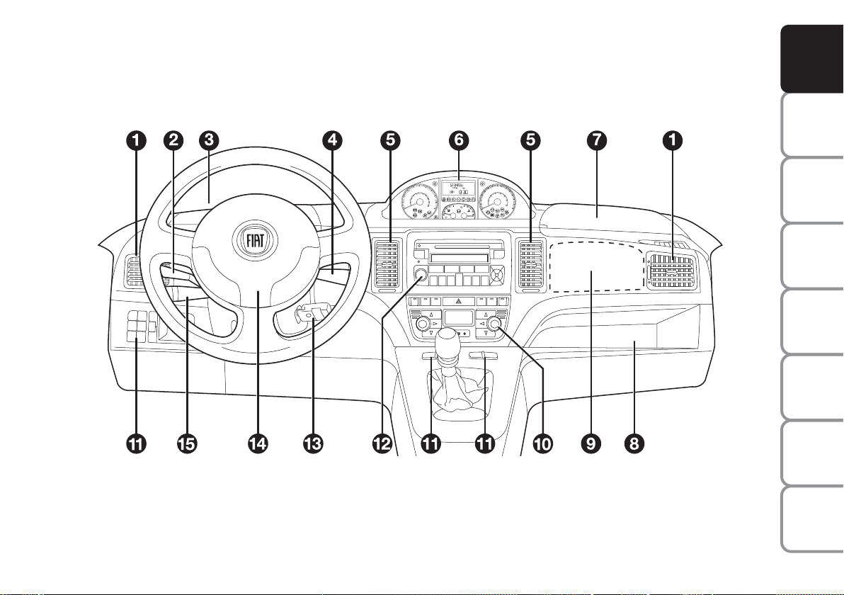
DASHBOARD
The presence and the position of the instruments and warning lights may vary according to the versions.
According to Customer’s requirements the upper and lower central console can offer different solutions, as shown in the following figures.
fig. 1
F0R0734m
1. Side vents - 2. Left-hand stalk - 3. Upper left oddment compartment - 4. Right-hand stalk - 5. Central vents -
6. Instrument panel - 7. Upper right oddment compartment housing the front passenger’s airbag deactivation switch - 8. Glove com-
partment - 9. Front passenger’s airbag - 10. Heating/ventilation/climate controls - 11. Control buttons - 12. Sound system (where
provided) - 13. Ignition switch - 14. Driver’s airbag - 15. Cruise Control (where provided).
DASHBOARD
AND CONTROLS
SAFETY
DEVICES
OF THE CAR
CORRECT USE
WARNING
MESSAGES
LIGHTS AND
IN AN
EMERGENCY
CAR
MAINTENANCE
TECHNICAL
SPECIFICATIONS
INDEX
5
Page 7
DASHBOARD
AND CONTROLS
SAFETY
DEVICES
OF THE CAR
CORRECT USE
WARNING
MESSAGES
LIGHTS AND
IN AN
EMERGENCY
CAR
MAINTENANCE
TECHNICAL
SPECIFICATIONS
INDEX
6
fig. 2
fig. 3
F0H0231m
F0H0232m
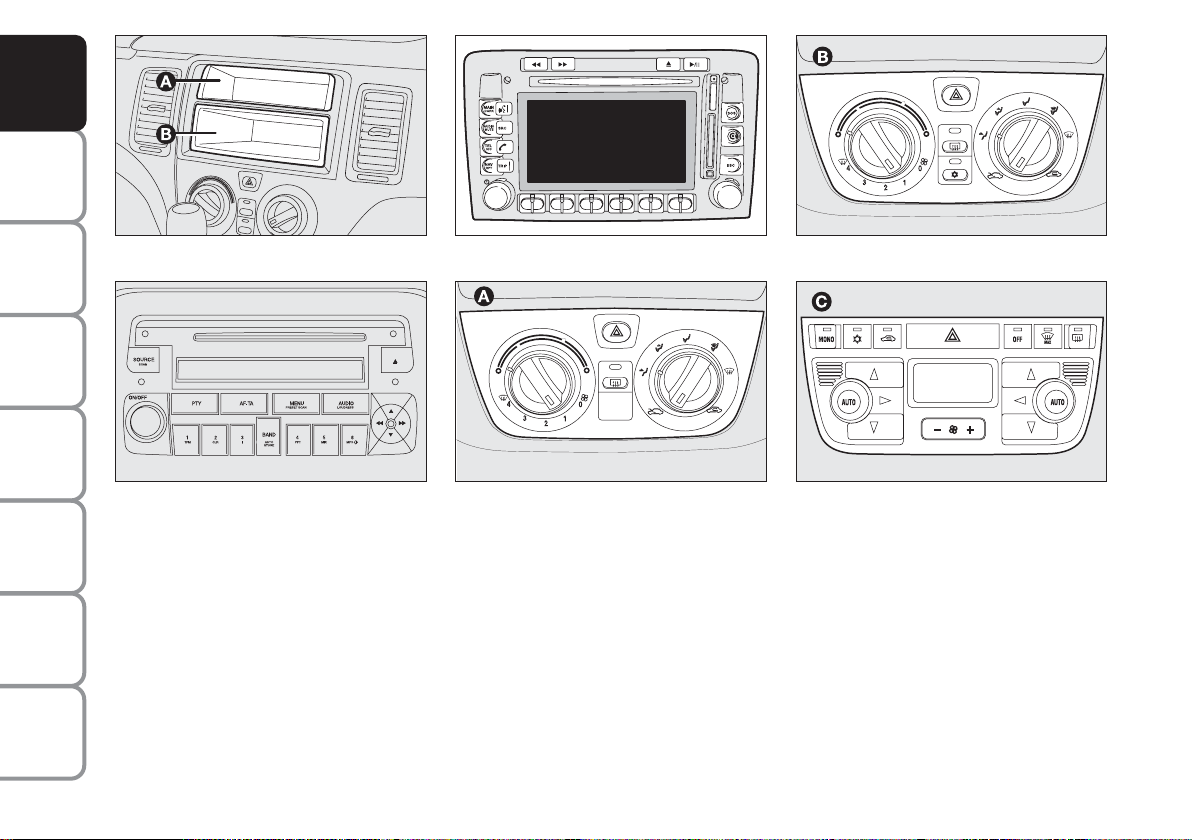
Upper central console:
❒ with fixed oddment compartment A
and removable oddment compartment (DIN) B for sound system installation fig. 2;
❒ with sound system upon request
fig. 3;
❒ with Connect Nav + fig. 4.
fig. 4
fig. 5
F0H0735m
F0H0233m
Lower central console:
❒ with heater A-fig. 5;
❒ with manual climate control system B-
fig. 6;
fig. 6
fig. 7
F0H0234m
F0H0235m
❒ with automatic two-zone climate con-
trol system C-fig. 7.
Page 8
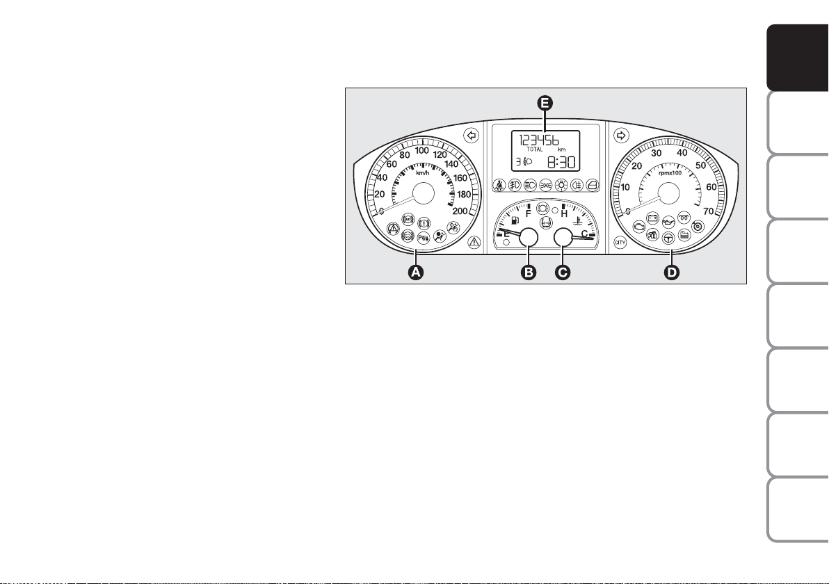
INSTRUMENT PANEL
Modal
A – Speedometer
B – Fuel gauge with reserve warning light
C – Engine coolant temperature gauge with
high temperature warning light
D – Rev counter
E – Multifunction display
DASHBOARD
AND CONTROLS
SAFETY
DEVICES
OF THE CAR
CORRECT USE
cm Warning lights fitted on Multijet
versions only
fig. 8
F0H0706m
WARNING
LIGHTS AND
IN AN
EMERGENCY
CAR
MAINTENANCE
TECHNICAL
SPECIFICATIONS
INDEX
7
MESSAGES
Page 9
DASHBOARD
AND CONTROLS
SAFETY
DEVICES
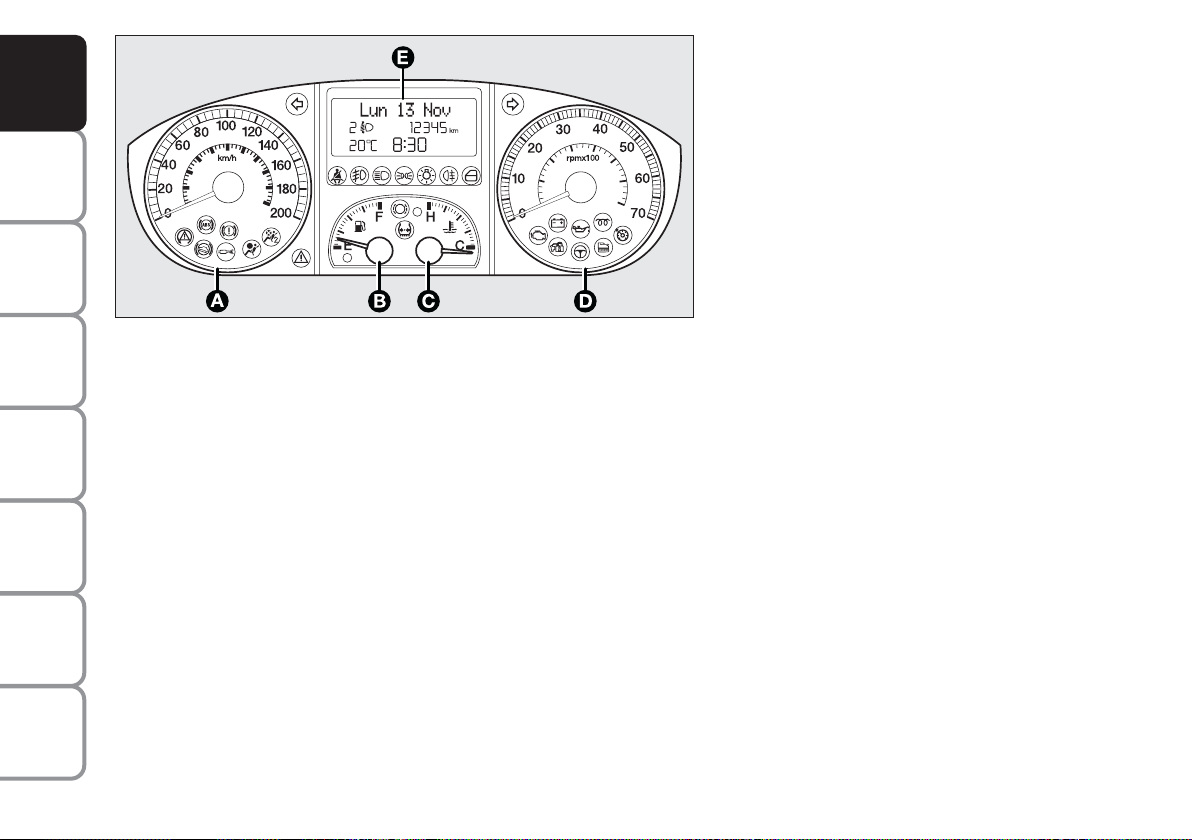
Comfort
A – Speedometer
B – Fuel gauge with reserve warning light
C – Engine coolant temperature gauge with
high temperature warning light
D – Rev counter
E – Reconfigurable multifunction display
OF THE CAR
CORRECT USE
WARNING
MESSAGES
LIGHTS AND
IN AN
EMERGENCY
CAR
MAINTENANCE
TECHNICAL
SPECIFICATIONS
INDEX
8
fig. 9
F0H0707m
cm Warning lights fitted on Multijet
sions only
ver-
Page 10
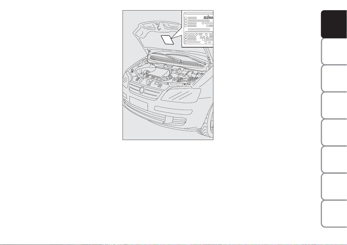
SYMBOLS
THE FIAT CODE SYSTEM
Special coloured labels have been attached
near or actually on some of the components of your Fiat Idea. These labels bear
symbols that remind you of the precautions to be taken as regards that particular component.
The plate summarising the symbols used
can be found under the bonnet fig. 10.
fig. 10
F0H0012m
To further protect you car from theft, it
has been fitted with an engine immobilising system. This system is automatically activated when the ignition key is removed.
An electronic device, in fact, is fitted in
each ignition key grip. The device transmits a radio-frequency signal when the engine is started through a special aerial built
into the ignition switch. The modulate signal, which changes each time the engine is
started, is the “password”, by means of
which the control unit recognises the key
and enables to start the engine.
DASHBOARD
AND CONTROLS
SAFETY
DEVICES
OF THE CAR
CORRECT USE
WARNING
MESSAGES
LIGHTS AND
IN AN
EMERGENCY
CAR
MAINTENANCE
TECHNICAL
SPECIFICATIONS
9
INDEX
Page 11
DASHBOARD
AND CONTROLS
SAFETY
DEVICES
OF THE CAR
CORRECT USE
WARNING
MESSAGES
LIGHTS AND
IN AN
EMERGENCY
CAR
MAINTENANCE
TECHNICAL
SPECIFICATIONS
OPERATION
Each time the car is started turning the ignition key to MAR, the Fiat CODE system control unit sends a recognition code
to the engine control unit to deactivate
the inhibitor.
The code is sent only if the Fiat CODE
system control unit has recognised the
code transmitted from the key.
Each time the ignition key is turned to the
STOP position, the Fiat CODE system
deactivates the functions of the engine
electronic control unit.
At starting, if the code has not been recognised correctly, the warning light
Y
will
come on.
In this case, the key should be moved to
the STOP position and then back to
MAR; if the lock continues, possibly try
again with the other key provided with the
car. If it is still not possible to start the car,
then contact a Fiat Dealership.
IMPORTANT Every key has its own code,
which must be memorised by the system
control unit. To memorise new keys, up
to a maximum of eight, apply to Fiat Dealership.
Warning light
coming on when
Y
driving
❒
If the warning light Yturns on, this
means that the system is running a selftest (for example for a voltage drop).
Should the inconvenience persists,
contact a Fiat Dealership.
The electronic components
inside the key may be damaged if the key is submitted to
sharp knocks.
KEY KIT AND DOOR
LOCKING
CODE CARD
(Optional for versions/markets
where applicable) fig. 11
The car is delivered with the keys and the
CODE card which bears the following:
❒
the electronic code A;
❒
the mechanical key code B to be given to the Fiat Dealership when ordering duplicate keys.
IMPORTANT In order to ensure perfect
efficiency of the electronic devices contained inside the keys, they should never
be exposed to direct sunlight.
All the keys and the CODE
card must be handed over to
the new owner when selling
the car.
INDEX
10
Page 12
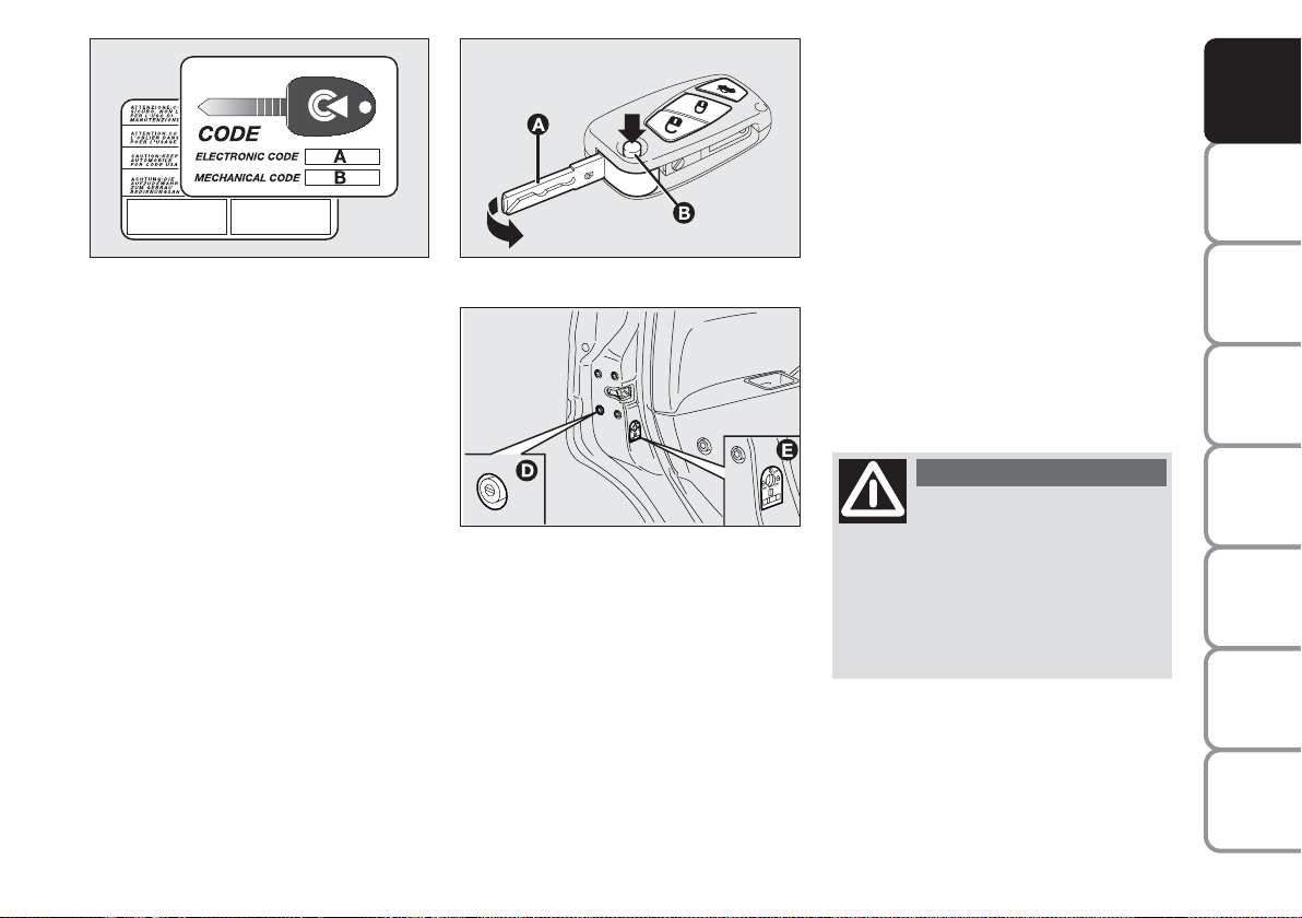
fig. 11
F0H0700m
MAIN KEY WITH REMOTE
CONTROL fig. 12
The metal insert A of the key is grip-retractable.
The key operates:
❒
the ignition switch;
❒
driver’s door lock;
❒
cut-in of door lock device D-fig. 13
when the electric system is failing (e.g.
run-down battery);
❒
cut-in of child lock safety device E on
rear doors.
fig. 12
fig. 13
F0H0701m
F0H0246m
Button B-fig. 12 opens the metal insert
A.
To refit the metal insert A into the key
grip:
❒
keep button B pressed
❒
move the metal insert A
❒
release button B and then turn the
metal insert A until hearing the click
as it locks into place.
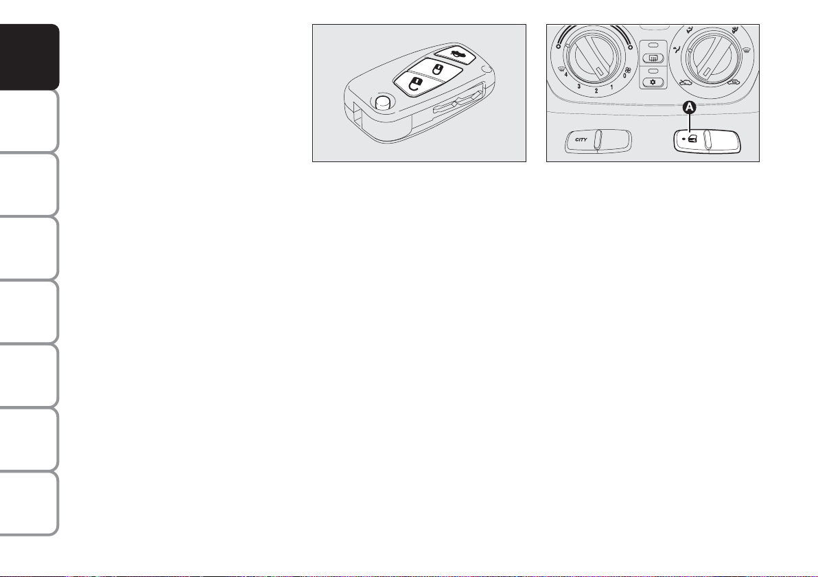
Button Ëunlocks the doors, the tailgate
and the fuel cap.
Button Álocks the doors, the tailgate and
the fuel cap.
Button
R
unlocks the boot.
IMPORTANT The remote control system
frequency can be disturbed by significant
radio transmissions outside the car (e.g:
mobile phones, HAM radio systems, etc.)
that could cause remote control malfunctioning.
WARNING
Button B-fig. 12 should only
be pressed when the key is
away from the body, in particular
from the eyes and from objects that
can be spoilt (e.g. clothes). Make sure
the key can never be touched by others, especially children, who may inadvertently press the button.
DASHBOARD
AND CONTROLS
SAFETY
DEVICES
OF THE CAR
CORRECT USE
WARNING
MESSAGES
LIGHTS AND
IN AN
EMERGENCY
CAR
MAINTENANCE
TECHNICAL
SPECIFICATIONS
11
INDEX
Page 13
DASHBOARD
AND CONTROLS
SAFETY
DEVICES
OF THE CAR
CORRECT USE
WARNING
MESSAGES
LIGHTS AND
IN AN
EMERGENCY
CAR
MAINTENANCE
Opening the doors and the tailgate
Pressing and keeping the pushbutton
pressed Ë: for a short time: remote unlocking of doors, boot lid, unlocking of fuel lid, timed switching on of inner roof
lamp and double blinking.
Doors will be unlocked automatically if the
fuel inertial cut-off switch comes into operation.
IMPORTANT The remote control system
frequency can be disturbed by significant
radio transmissions outside the car (e.g:
mobile phones, HAM radio systems, etc.)
that could cause remote control malfunctioning.
fig. 14
F0H0702m
Closing the doors and the tailgate
Pressing and keeping the pushbutton
pressed Á: for a short time: remote locking of doors, boot lid, locking of fuel lid,
switching off of inner roof lamp and single blinking.
fig. 15
F0H0703m
Deterrence led
When locking the doors, the led on button A-fig. 15 switches on for about 3 seconds and than starts flashing (deterrence
function). Once doors are locked, if one
or more doors or the tailgate are not
closed correctly, the led and direction indicators will start flashing quickly.
IMPORTANT The remote control system
frequency can be disturbed by significant
radio transmissions outside the car (e.g:
mobile phones, HAM radio systems, etc.)
that could cause remote control malfunctioning.
TECHNICAL
SPECIFICATIONS
INDEX
12
Page 14
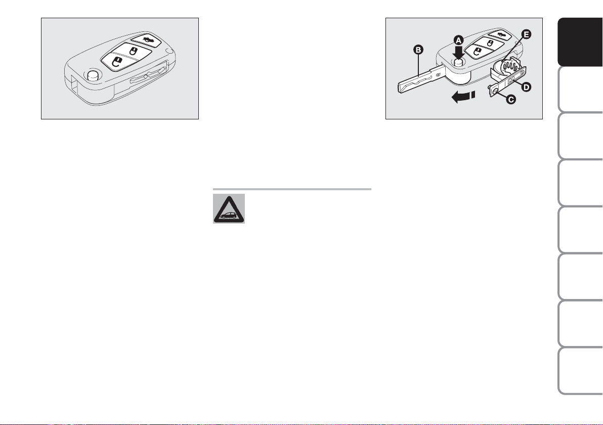
fig. 16
F0H0702m
Opening the tailgate from
the outside fig. 16
The tailgate can be opened from the outside by pressing the remote control button R. Tailgate opening will obtain double direction indicators flashing.
IMPORTANT The remote control system
frequency can be disturbed by significant
radio transmissions outside the car (e.g:
mobile phones, HAM radio systems, etc.)
that could cause remote control malfunctioning.
Locking doors from the inside
fig. 15
With doors closed, press the button A located on the dashboard in central position,
to lock (led on the button ON) or unlock
(led on the button OFF) the doors.
IMPORTANT Door locking from inside
will not cut-in if one door is not prefectly closed or there is a system failure.
If the cause of the failure is removed, the
device will start working properly.
If the inside locking button is
pressed accidentally, when
getting out of the car only the
doors used will unlock whereas the tailgate will stay locked.To realign the system, press the lock / unlock
button again.
fig. 17
F0H0704m
Replacing the battery of the key
with remote control fig. 17
Battery replacement:
❒
press button A and move the metal insert B to open position;
❒
use a finely-tipped screwdriver to turn
the screw C;
❒
pull out the battery holder D and replace the battery E making sure that
the bias is correct;
❒
re-insert the battery holder D in the
key and lock it turning the screw C.
DASHBOARD
AND CONTROLS
SAFETY
DEVICES
OF THE CAR
CORRECT USE
WARNING
MESSAGES
LIGHTS AND
IN AN
EMERGENCY
CAR
MAINTENANCE
TECHNICAL
INDEX
13
SPECIFICATIONS
Page 15

Request for additional remote
controls
DASHBOARD
The system can recognise up to 8 keys
with incorporated remote control. Should
AND CONTROLS
a new key with remote control be necessary, contact a Fiat Dealership, taking
SAFETY
with you the CODE card, a personal iden-
DEVICES
tity document and the car’s ownership
documents.
fig. 18
F0H0014m
fig. 19
F0H0322m
OF THE CAR
CORRECT USE
WARNING
MESSAGES
LIGHTS AND
IN AN
EMERGENCY
CAR
MAINTENANCE
TECHNICAL
SPECIFICATIONS
INDEX
14
Used batteries are harmful to
the environment. They should
be disposed of as specified by
law in the special containers
provided, or take them to a Fiat Dealership, which will deal with their disposal.
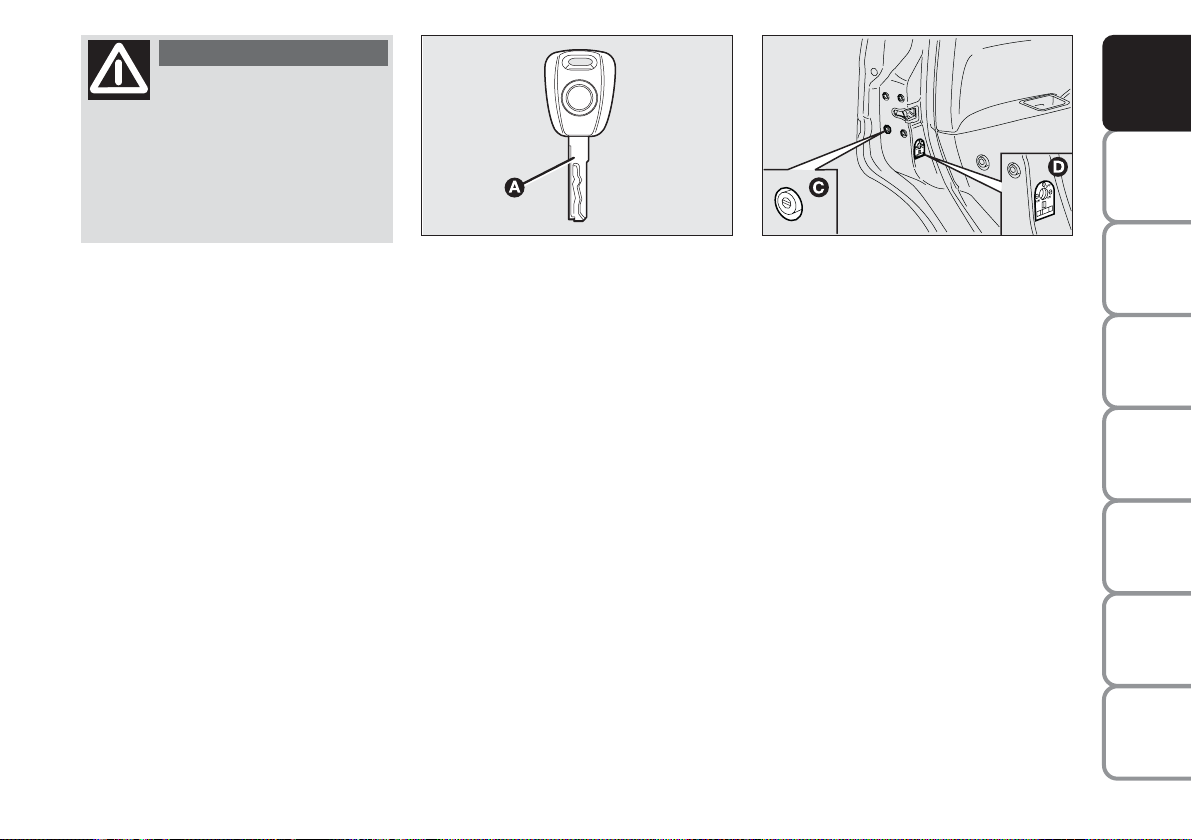
KEY WITHOUT REMOTE
CONTROL (SPARE KEY)
(where required)
The metal insert A-fig. 18 of the key is
grip-retractable.
The key operates:
❒
the ignition switch;
❒
the driver’s door;
❒
cut-in of door lock device C-fig. 19
when the electric system is failing (e.g.
run-down battery;
❒
cut-in of child lock safety device Dfig. 19 on rear doors.
Button B-fig. 18 opens the metal insert
A.
To refit the metal insert A into the key
grip:
❒
keep button B pressed
❒
move the metal insert A
❒
release button B and then turn the
metal insert A until hearing the click
as it locks into place.
Page 16
WARNING
Button B should only be
pressed when the key is
away from the body, in particular
from the eyes and from objects that
can be spoilt (e.g. clothes). Make sure
the key can never be touched by others, especially children, who may inadvertently press the button.
fig. 20
F0H0705m
fig. 21
F0H0322m
DASHBOARD
AND CONTROLS
SAFETY
DEVICES
KEY WITHOUT REMOTE
CONTROL (SPARE KEY)
(where required)
The metal insert A-fig. 20 of the key is
fixed.
The key operates:
❒
the ignition switch;
❒
the driver’s door;
❒
cut-in of door lock device C-fig. 21
when the electric system is failing (e.g.
run-down battery);
❒
cut-in of child lock safety device Dfig. 21 on rear doors.
OF THE CAR
CORRECT USE
WARNING
LIGHTS AND
IN AN
EMERGENCY
CAR
MAINTENANCE
TECHNICAL
SPECIFICATIONS
INDEX
15
MESSAGES
Page 17

The main functions that can be activated with the keys (with or without remote control) are the following:
DASHBOARD
AND CONTROLS
SAFETY
DEVICES
OF THE CAR
CORRECT USE
WARNING
MESSAGES
LIGHTS AND
IN AN
EMERGENCY
CAR
MAINTENANCE
TECHNICAL
SPECIFICATIONS
Type of
key
Spare key without
remote control
Main key with
remote control
Direction indicators
flashing (only with key with
remote control)
Deterrence led
Pressing the pushbutton Ë enables fuel lid to be opened.
Door opening
Key turning counterclockwise
(driver’s side)
Key turning counterclockwise
(driver’s side)
Pressing briefly button Ë
Two flashings
Turning off
Door locking
from the outside
Key turning clockwise
(driver’s side)
Key turning clockwise
(driver’s side)
Pressing briefly button Á
One flashing
Turned on fixed for approx.
3 seconds, followed by deterrence
led flashing
Boot
opening
Pressing on button R
Two flashings
Deterrence led flashing
INDEX
16
Page 18
WARNING
Child lock device A is prop-
erly engaged only if after
turning the revolving plug it clicks in
horizontal position (1).
DASHBOARD
AND CONTROLS
SAFETY
DEVICES
fig. 22
F0H0101m
CHILD LOCK fig. 22
To prevent opening the rear doors from
the inside.
This device can be engaged only with
doors open.
❒
position 1 - engaged (door locked);
❒
position 2 - disengaged (door openable from inside).
The device A is engaged even if the doors
are unlocked by the centralised system.
IMPORTANT Always use the lock when
transporting children.
IMPORTANT After engaging the lock,
check by trying to open a rear door with
the internal handle.
WARNING
Child lock device A is prop-
erly disengaged only if after
turning the revolving plug it clicks in
vertical position (2).
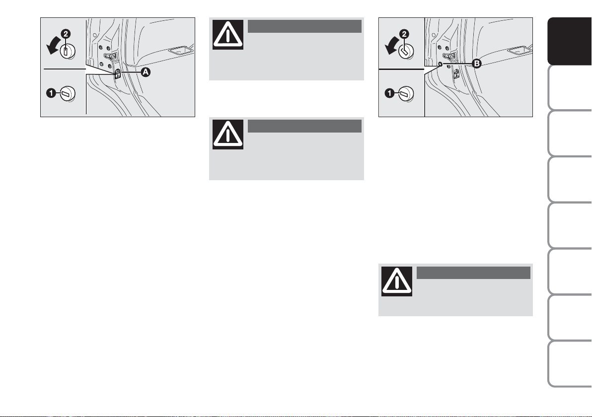
EMERGENCY DEVICE
FOR LOCKING DOORS
FROM THE OUTSIDE fig. 23
Doors are fitted with a special device enabling to lock all doors when the electric
system is failing (no current).
To lock the doors:
❒
fit the ignition key into the revolving
plug B;
❒
turn the device to position 1 and close
the door.
fig. 23
To open the doors:
❒
fit the ignition key into the revolving
plug of the driver’s door and turn it
counterclockwise;
❒
open the driver’s door;
❒
once inside the car, open the other
doors using the levers set on door
handles.
WARNING
Never operate the child lock
device and the door handle
at the same time.
F0H0247m
OF THE CAR
CORRECT USE
WARNING
LIGHTS AND
IN AN
EMERGENCY
CAR
MAINTENANCE
TECHNICAL
SPECIFICATIONS
INDEX
17
MESSAGES
Page 19
DASHBOARD
AND CONTROLS
SAFETY
DEVICES
OF THE CAR
CORRECT USE
WARNING
MESSAGES
LIGHTS AND
IN AN
EMERGENCY
CAR
MAINTENANCE
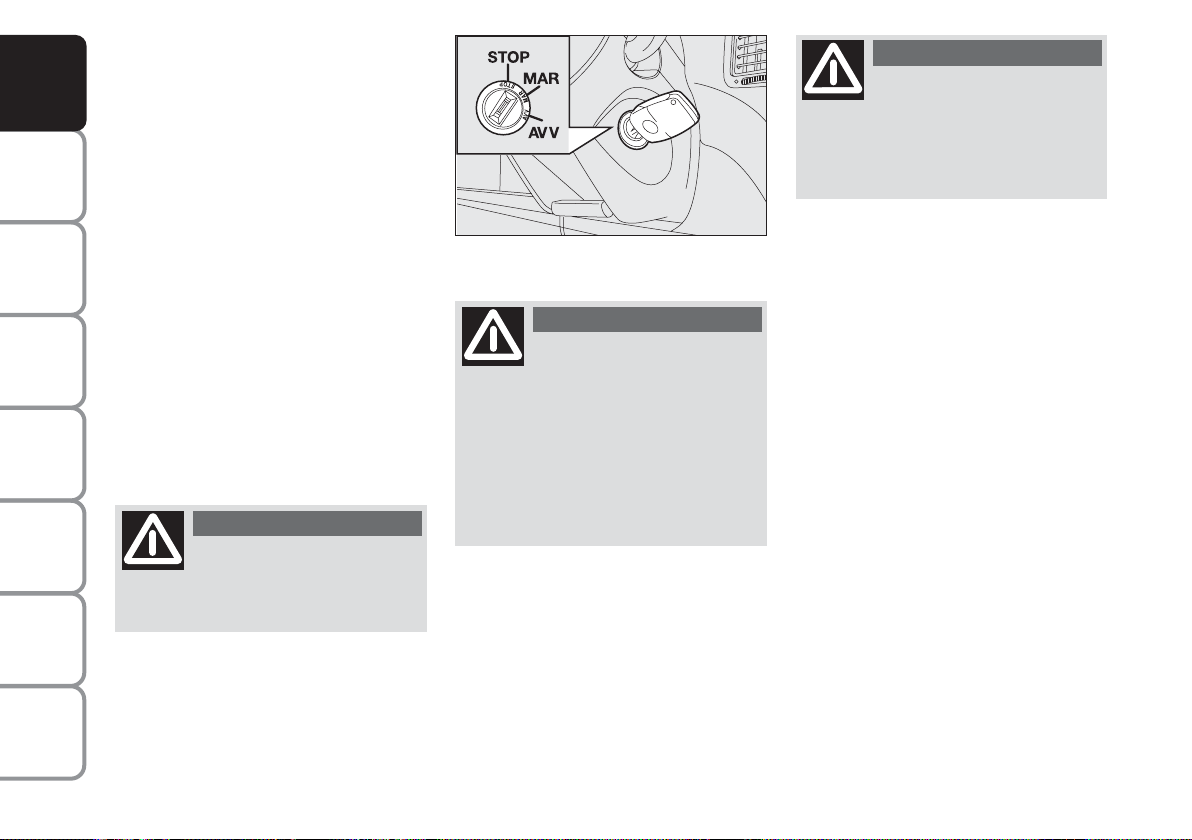
IGNITION SWITCH
The key can be turned to 3 different positions fig. 24:
❒
STOP: engine off, key can be removed, steering column locked. Certain electrical devices (e.g.: sound system, power windows…) can work.
❒
MAR: driving position. All electrical
devices are powered.
❒
AVV: engine starting (unstable position).
The ignition switch is fitted with a safety
mechanism that, in the event the engine is
not started, turns back the ignition key to
STOP before repeating the starting operation.
WARNING
If the ignition device is tam-
pered with (e.g.: attempted
theft), have it checked over by a Fiat
Dealership.
fig. 24
F0H0021m
WARNING
When getting out of the car,
always remove the key to
prevent any occupants from accidentally activating the controls. Remember to engage the handbrake. If
the car is parked on uphill slope to
engage the first gear. If the car is facing downhill, engage the reverse gear.
Never leave unsupervised children in
the car.
WARNING
Never remove the ignition
key while the car is moving.
The steering wheel would automatically lock as soon as you try to turn
it. This also applies when the car is
being towed.
STEERING COLUMN LOCK
Engaging
When the key is to STOP remove the
key and turn the steering wheel until it
locks.
Disengaging
Rock the steering wheel slightly as you
turn the ignition key to MAR.
TECHNICAL
SPECIFICATIONS
INDEX
18
Page 20
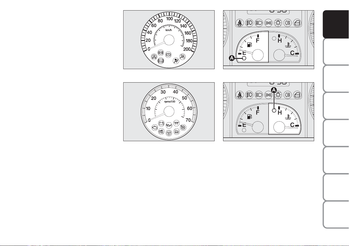
INSTRUMENTS
SPEEDOMETER fig. 25
Speed indicator.
REV. COUNTER fig. 26
Engine rpm indicator.
IMPORTANT The electronic injection
control system gradually shuts off the flow
of fuel when the engine is “over-revving”
resulting in a gradual loss of engine power.
When the engine is idling, the rev counter
may indicate a gradual or sudden highering of the speed.
This is normal as it takes place during normal operation, for example when activating the climate control system or the fan.
In particular a slow change in the speed
preserves the battery charge.
FUEL LEVEL GAUGE fig. 27
This shows the amount of fuel left in the
fuel tank (see the indications given in paragraph “At the filling station").
fig. 25
fig. 26
F0H0708m
F0H0022m
The reserve warning light A turns on to
indicate that approx. 6 litres of fuel are left
in the tank.
Do not travel with the fuel tank almost
empty: the gaps in fuel delivery could damage the catalyst.
fig. 27
fig. 28
F0H0023m
F0H0024m
ENGINE COOLANT
TEMPERATURE GAUGE fig. 28
The turning on of the warning light A in-
dicates that the coolant fluid temperature
is too high; in this case, stop the engine
and contact a Fiat Dealership.
DASHBOARD
AND CONTROLS
SAFETY
DEVICES
OF THE CAR
CORRECT USE
WARNING
MESSAGES
LIGHTS AND
IN AN
EMERGENCY
CAR
MAINTENANCE
TECHNICAL
SPECIFICATIONS
19
INDEX
Page 21
This shows the temperature of the engine
coolant fluid and begins working when the
fluid temperature exceeds approx. 50°C.
DASHBOARD
Under normal conditions, the needle
AND CONTROLS
should hover around the middle of the
scale according to the working conditions.
SAFETY
IMPORTANT If the needle reaches the
DEVICES
low temperature area with warning light
A on, this means that there is a failure.
Contact a Fiat Dealership.
MULTIFUNCTIONAL
DISPLAY
(on two-line modal
panel)
The car can be equipped with a multifunction display that shows useful information for car driving according to the
settings made.
fig. 29
F0H0027m
OF THE CAR
CORRECT USE
WARNING
MESSAGES
LIGHTS AND
IN AN
EMERGENCY
CAR
MAINTENANCE
TECHNICAL
SPECIFICATIONS
INDEX
20
If the needle reaches the red
area, stop the engine immediately and contact a Fiat
Dealership.
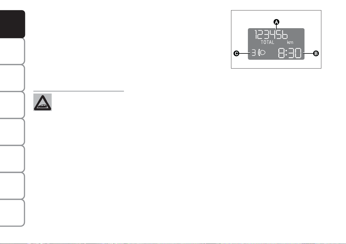
“STANDARD” SCREEN fig. 29
The standard screen shows the following
information:
A Odometer (viewing of covered km or
miles)
B Time (always displayed, even with ig-
nition key removed and front doors
closed)
C Headlight aiming position (only with
dipped beam headlights on).
NOTE When opening one of the front
doors, the display turns on and shows the
clock and the kilometres or miles covered
for a few seconds.
Page 22
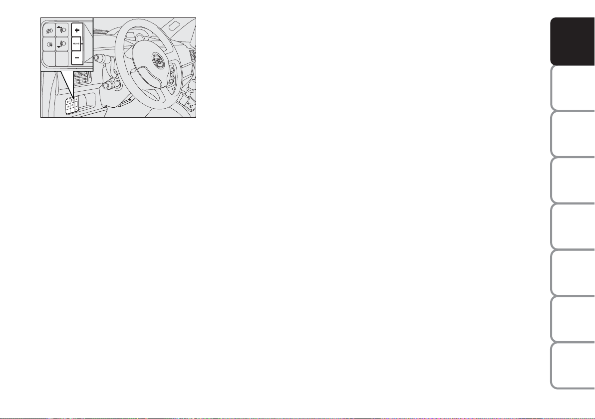
fig. 30
F0H0736m
CONTROL BUTTONS fig. 30
+
To scroll the next items on the displayed menu and the related options
or increase the displayed value.
MODE Press briefly to access the menu
and/or go to next screen or confirm the required menu option.
Hold pressed to go back to the
standard screen.
–
To scroll the previous items on the
displayed menu and the related options or reduce the displayed value.
NOTE Buttons + and – activate different
functions according to the following situations.
SETUP MENU
The “Setup Menu” is used to make the following settings and/or adjustments:
❒
ADJUSTING THE CLOCK
❒
ADJUSTING THE BUZZER VOLUME
❒
SETTING THE SPEED LIMIT
❒
SETTING THE UNIT
Adjusting the clock
The car is delivered with the clock adjusted for 24 hours.
To set the required time proceed as follows:
❒
press the button MODE several times
until the text “Hour” appears;
❒
press the button + to increase the
time by one minute;
❒
press the button – to reduce the time
by one minute;
Hold the buttons + or – pressed for a few
seconds to automatically start quick increase or reduction of the time until the
buttons are released.
❒
Press the button MODE and hold it
pressed for over 2 seconds to confirm
the time change.
Adjusting the buzzer volume
To adjust the desired volume proceed as
follows:
❒
press the button MODE several times
until the text “bUZZ” appears;
❒
press the button + to increase the
volume;
❒
press the button – to reduce the volume;
❒
press the button MODE and hold it
pressed for over 2 seconds to confirm
the volume change.
Indication that the set peed limit has
been exceeded
Proceed as described below to set a reference car speed value beyond which the
system warns the driver about this by displaying a message and starting the buzzer.
The car is delivered with this function in
“OFF”mode.
DASHBOARD
AND CONTROLS
SAFETY
DEVICES
OF THE CAR
CORRECT USE
WARNING
MESSAGES
LIGHTS AND
IN AN
EMERGENCY
CAR
MAINTENANCE
TECHNICAL
SPECIFICATIONS
21
INDEX
Page 23
DASHBOARD
AND CONTROLS
SAFETY
DEVICES
OF THE CAR
CORRECT USE
WARNING
MESSAGES
LIGHTS AND
IN AN
EMERGENCY
CAR
MAINTENANCE
Set this function as follows:
❒
press the button MODE several times
until the text “SPEEd” appears;
❒
press the button + to increase the
speed value (max. limit being 250
Km/h);
❒
press the button – to reduce the
speed value (min. limit being 30 Km/h
below which the system goes back to
“OFF” mode);
❒
press the button MODE and hold it
pressed for over 2 seconds to confirm
the speed setting.
Setting the unit
To set the required unit (kilometres or
miles) proceed as follows:
❒
press the button MODE several times
until the text “Unit” appears;
❒
press the button + or – to change the
unit;
❒
press the button MODE and hold it
pressed for over 2 seconds to confirm
the unit setting.
Viewing of the fuel cut-off inertial
switch tripping
The screen automatically appears whenever the fuel cut-off inertial switch trips after a significant collision.
This switch stops fuel supply.
See the information provided in the dedicated chapter “Fuel cut-off inertial
switch”.
WARNING
If, after the message
“FPSon” appears, you smell
fuel or see leaks from the fuel supply
system, do not reset the switch to
avoid the risk of starting a fire.
TECHNICAL
SPECIFICATIONS
INDEX
22
Page 24
MULTIFUNCTIONAL
DISPLAY
(on three-line comfort
panel)
DASHBOARD
AND CONTROLS
The car can be equipped with a multifunction display that shows useful information for car driving according to the
settings made.
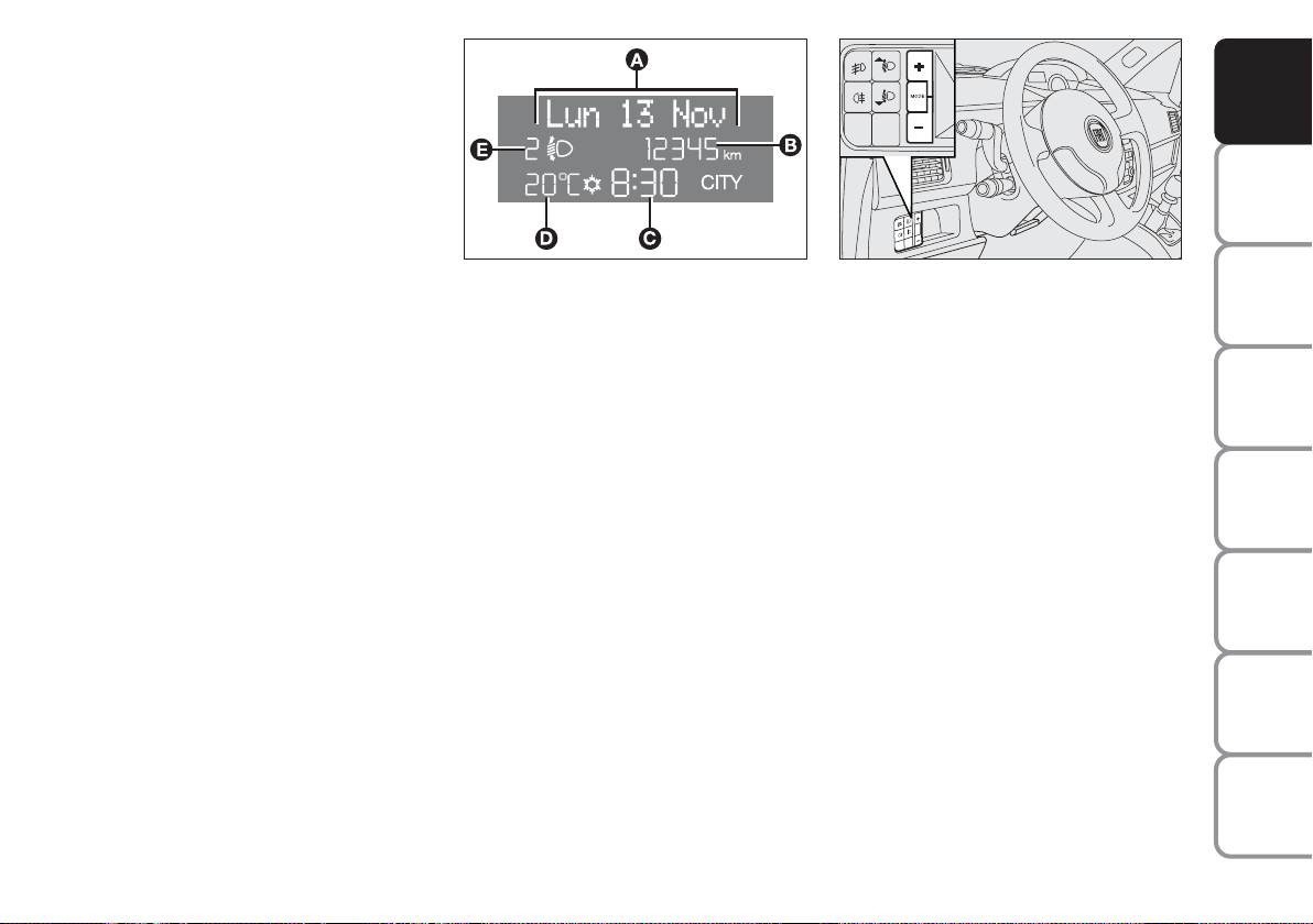
“STANDARD” SCREEN fig. 31
The standard screen shows the following
information:
A Date
B Odometer (viewing of covered km or
miles)
C Time (always displayed, even with ig-
nition key removed and front doors
closed)
fig. 31
F0H09000m
D External temperature
E Headlight aiming position (only with
dipped beam headlights on)
NOTE When opening one of the front
doors, the display turns on and shows the
clock and the kilometres or miles covered
for a few seconds.
fig. 32
F0H0736m
CONTROL BUTTONS fig. 32
+
To scroll the next items on the displayed menu and the related options
or increase the displayed value.
MODE Press briefly to access the menu
and/or go to next screen or confirm the required menu option.
Hold pressed to go back to the
standard screen.
–
To scroll the previous items on the
displayed menu and the related options or reduce the displayed value.
NOTE Buttons + and – activate different
functions according to the following situations.
SAFETY
DEVICES
OF THE CAR
CORRECT USE
WARNING
MESSAGES
LIGHTS AND
IN AN
EMERGENCY
CAR
MAINTENANCE
TECHNICAL
SPECIFICATIONS
INDEX
23
Page 25

DASHBOARD
AND CONTROLS
SAFETY
DEVICES
OF THE CAR
CORRECT USE
WARNING
MESSAGES
LIGHTS AND
IN AN
EMERGENCY
CAR
MAINTENANCE
TECHNICAL
SPECIFICATIONS
Adjustment of headlight aiming
device (only with dipped beam
headlights on)
– when the standard screen is enabled, the
headlight aiming device can be regulated
(refer to paragraph “Headlights” in this
section).
Setup menu
– to scroll the previous and next items in
the menu;
– to increase or decrease values during
setting operations.
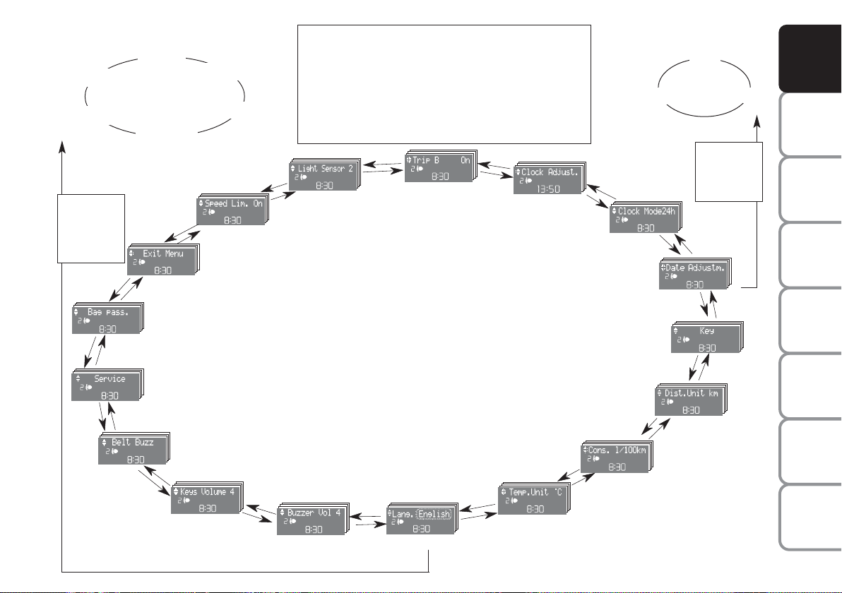
SETUP MENU fig. 33
The menu comprises a series of functions
arranged in a cycle which can be selected
through buttons + and – to access the dif-
ferent “select” operations and settings
(setup) described in the following paragraphs.
The setup menu is activated by pressing
briefly button MODE.
Intermittent pressing of buttons + and –
enables scrolling of the setup menu options.
Handling modes are different according to
the characteristic of the option selected.
NOTE If the Connect Nav+ system is installed, only the following functions can be
adjusted/set from the Instrument Panel:
“Brightness”, “Speed Beep”, Light Sensors” (where provided), “Seat belt
Buzzer” and “Passenger’s Airbag”. The
other functions are displayed on the Connect Nav+ system which is used to adjust/set them.
Selecting a menu option
– Briefly press button MODE to select
the menu option that needs to be
changed.
– Press buttons + and – (by single pressing) to select the new setting.
– Briefly press button MODE to store the
new setting and at the same time go back
to the previously selected menu option.
Selecting the “Set Date”
and “Set time”
– Briefly press button MODE to select
the first value to be changed (e.g. hours
/minutes or year / month / day).
– Press buttons + and – (by single pressing) to select the new setting.
– Briefly press button MODE to store the
new setting and at the same time go to the
next setup menu option. If the processed
option is the last one, the system brings
you back to the previously selected option
of the main menu.
Prolonged pressing of the button
MODE enables:
– exiting the setup menu page and saving
of the changes already stored by the driver (and confirmed by briefly pressing the
button MODE).
The setup menu page is timed. Only the
changes saved by the user by briefly pressing MODE are saved when the menu is
automatically closed.
INDEX
24
Page 26
Example:
Italiano
Português
MODE
brief button
pressing
+
+
fig. 33
–
+
–
Deutsch
Français
+
EXITING THE MENU
–
BAG. PASS.
SERVICE
BELT BUZZ.
(*) where provided
VOL. BUTTONS
–
+
English
Español
–
SPEED BEEP.
VOL. BUZZER
–
+
From the standard screen, briefly press button MODE
to start browsing. Press + or – to browse within the
menu. NOTE Only the short menu may be accessed
for reasons of safety while the car is moving (“Brightness” and “Speed Beep” settings). Stop the car to access the full menu. In cars equipped with a Connect
Nav+ system, many functions are viewed from the navigator display.
+
LIGHT SENS.
–
+
–
TRIP B
LANGUAGE
–
+
+
–
CLOCK SETTING
TEMP. UNIT
–
+
Example:
+
–
CLOCK MODE
SETTING THE DATE
DIST. UNIT
CONSUMPTION
–
+
F0H0000m
Day
Year
–
Month
MODE
brief button
pressing
+
–
+
KEY
–
+
–
+
(*) This function may only be
displayed after the SBR system is deactivated by a Fiat
Dealership.
DASHBOARD
AND CONTROLS
SAFETY
DEVICES
OF THE CAR
CORRECT USE
WARNING
MESSAGES
LIGHTS AND
IN AN
EMERGENCY
CAR
MAINTENANCE
TECHNICAL
SPECIFICATIONS
INDEX
25
Page 27

DASHBOARD
AND CONTROLS
SAFETY
DEVICES
OF THE CAR
CORRECT USE
WARNING
MESSAGES
LIGHTS AND
IN AN
EMERGENCY
CAR
MAINTENANCE
Speed limit (Speed beep)
This function enables setting of the car
speed limit (km/h or mph). When this limit is exceeded the driver is immediately
alerted (see section “Warning lights and
messages”).
To set the speed limit, proceed as follows:
– briefly press button MODE: the display
will show the wording “Speed Beep”;
– press button + or – to select speed lim-
it activation (On) or deactivation (Off);
– if the function is on, press buttons + or
– to select the required speed limit and
then press MODE to confirm.
Note The speed may be set in the range
from 30 to 250 km/h, or from 20 to 155
mph according to the previously chosen
unit (see “Setting the distance unit”) described below. The setting will increase/decrease by 5 units each time button +/– is pressed. Hold button +/–
pressed to increase/decrease the setting
rapidly. Complete the setting by briefly
pressing the button when you approach
the required value.
– briefly press button MODE to go back
to the menu screen or press the button
for a prolonged time to go back to the
standard screen without storing the settings.
To cancel the setting, proceed as follows:
– briefly press button MODE: ON flashes on the display;
– press button +: OFF flashes on the display;
– briefly press button MODE to go back
to the menu screen or press the button
for a prolonged time to go back to the
standard screen without storing the settings.
TECHNICAL
SPECIFICATIONS
INDEX
26
Page 28

Adjusting the sensitivity
of the automatic headlight sensor
(Light sensor) (where provided)
This function is used to adjust the dusk
sensor sensitivity according to three levels (level 1 = minimum, level 2 = medium,
level 3 = maximum); the higher the sensitivity, the lower the quantity of external light needed to switch the headlights
on. The car is delivered with this function
set to level “2”.
To change this setting:
– briefly press button MODE: the previously set level flashes on the display;
– press button + or – for selecting the desired level;
– briefly press button MODE to go back
to the menu screen or press the button
for a prolonged time to go back to the
standard screen without storing the settings.
Trip B On/Off (Trip B)
Through this option it is possible to activate (On) or deactivate (Off) the Trip B
(partial trip) display.
For further information see section “Trip
computer”.
For activation / deactivation, proceed as
follows:
– briefly press button MODE: ON or
OFF flashes on the display (according to
previous setting);
– press button + or – for selecting the desired value;
– briefly press button MODE to go back
to the menu screen or press the button
for a prolonged time to go back to the
standard screen without storing the settings.
Setting the clock (Set time)
This function enables setting of the clock.
To set the clock proceed as follows:
– briefly press button MODE: the display
shows the “hours” flashing;
– press button + or – to set the clock;
– briefly press button MODE: “minutes”starts flashing on the display;
– press button + or – to set the clock.
Note The setting increases or decreases
by one unit each time button + or – is
pressed. Hold the button pressed to automatically start a quick increase/decrease
of the set value. Complete the setting by
briefly pressing the button when the required setting is approached.
– briefly press button MODE to go back
to the menu screen or press the button
for a prolonged time to go back to the
standard screen without storing the settings.
DASHBOARD
AND CONTROLS
SAFETY
DEVICES
OF THE CAR
CORRECT USE
WARNING
MESSAGES
LIGHTS AND
IN AN
EMERGENCY
CAR
MAINTENANCE
TECHNICAL
INDEX
27
SPECIFICATIONS
Page 29

DASHBOARD
AND CONTROLS
SAFETY
DEVICES
OF THE CAR
CORRECT USE
WARNING
MESSAGES
LIGHTS AND
IN AN
EMERGENCY
CAR
MAINTENANCE
12h/24h clock mode
(Clock mode)
This function enables setting the screen to
either 12 or 24 hour mode.
Proceed as follows:
– briefly press button MODE: 12h or 24h
starts flashing on the display (depending
on the previously set parameter);
– press button + or – for selecting the desired value;
– briefly press button MODE to go back
to the menu screen or press the button
for a prolonged time to go back to the
standard screen without storing the settings.
Setting the date (Set Date)
This function enables updating the date
(year - month - day).
To update the date proceed as follows:
– briefly press button MODE: the year
starts flashing on the display;
– briefly press button + or – to set the
year;
– briefly press button MODE: the month
starts flashing on the display;
– press button + or – to set the month;
– briefly press button MODE: the day
starts flashing on the display;
– press button + or – to set the day.
NOTE The setting increases or decreases by one unit each time button + or –
is pressed. Hold the button pressed to
start automatic quick increase/ decrease
of the setting. Complete the setting by
briefly pressing the button when the required setting is approached.
– briefly press button MODE to go back
to the menu screen or press the button
for a prolonged time to go back to the
standard screen without storing the settings.
Release of doors and tailgate (Key)
This function enables the release of the
front and rear doors, the release of the
driver's door only or the release of all the
doors including the tailgate.
To set the function, proceed as follows:
– press the MODE button for a short
time, the display shows “Open doors”,
“Op. drv.door” and “Open all”.
– press + or – to select; the selected item
will flash.
– Press MODE for a short time to return
to the menu screen or press the button
for a longer time to return to the standard
screen without confirming the selection.
TECHNICAL
SPECIFICATIONS
INDEX
28
Page 30

Unit - “distance” (Dist. unit)
With this function it is possible to set the
units for distance covered (km or mi).
To set the required unit proceed as follows:
– briefly press button MODE: km or mi
will flash on the display (according to previous setting);
– press button + or – for setting;
– briefly press button MODE to go back
to the menu screen or press the button
for long to go back to the standard screen
without storing settings.
Setting the consumption unit
(Consumption)
This function enables setting the unit for
the amount of fuel consumed (km/l, l/100
or mpg) depending on the distance unit selected (either km or miles - see previous
paragraph “Distance Unit”).
If the distance unit set is “km”, the display enables setting of the fuel consumption unit (km/l or l/100) depending on the
amount of fuel consumed. If the distance
unit set is “mi”, the display shows the fuel consumption unit in “mpg”.
Set this value as follows:
– briefly press button MODE: either km/l
or l/100 starts flashing on the display (depending on the previously set parameter);
– press button + or – for selecting the desired value;
– briefly press button MODE to go back
to the menu screen or press the button
for a prolonged time to go back to the
standard screen without storing the settings.
DASHBOARD
AND CONTROLS
SAFETY
DEVICES
OF THE CAR
CORRECT USE
WARNING
MESSAGES
LIGHTS AND
IN AN
EMERGENCY
CAR
MAINTENANCE
TECHNICAL
INDEX
29
SPECIFICATIONS
Page 31

DASHBOARD
AND CONTROLS
SAFETY
DEVICES
OF THE CAR
CORRECT USE
WARNING
MESSAGES
LIGHTS AND
IN AN
EMERGENCY
CAR
MAINTENANCE
Setting the temperature unit
(Temp. unit)
This function enables setting of the required temperature unit (either °C or °F).
To set the required unit proceed as follows:
– briefly press button MODE: either °C
or °F starts flashing on the display (depending on the previously set parameter);
– press button + or – for selecting the desired value;
– briefly press button MODE to go back
to the menu screen or press the button
for a prolonged time to go back to the
standard screen without storing the settings.
Selecting the language (Language)
The messages can be displayed in the following languages: Italian, German, English,
Spanish, French, Portuguese.
To set the required language proceed as
follows:
– briefly press button MODE: the previously set “language” starts flashing on the
display;
– press button + or – for selecting the desired language;
– briefly press button MODE to go back
to the menu screen or press the button
for a prolonged time to go back to the
standard screen without storing the settings.
Adjusting the failure/warning
buzzer volume (Buzzer Volume)
With this function the volume of the
buzzer accompanying any failure/warning
indication can be adjusted according to 8
levels. To adjust the desired volume proceed as follows:
– briefly press button MODE: the previously set volume “level” starts flashing on
the display;
– press button + or – for selecting the desired volume level;
– briefly press button MODE to go back
to the menu screen or press the button
for a prolonged time to go back to the
standard screen without storing the settings.
TECHNICAL
SPECIFICATIONS
INDEX
30
Page 32

Adjusting the button volume
(Button Vol.)
This function enables setting the volume
of the roger-beep accompanying the activation of buttons MODE, + and – according to 8 levels.
To adjust the desired volume proceed as
follows:
– briefly press button MODE: the previously set volume “level” starts flashing on
the display;
– press button + or – to set the volume
level;
– briefly press button MODE to go back
to the menu screen or press the button
for a prolonged time to go back to the
standard screen without storing the settings.
S.B.R. buzzer reactivation
(Belt Buzzer) (where provided)
This function can only be displayed after
Fiat Dealership has deactivated the S.B.R.
system (see paragraph “S.B.R. system” in
section “Safety devices”).
Scheduled Servicing (Service)
This function enables viewing of information on proper car servicing depending on
the kilometres travelled or daily intervals.
This information is consulted as follows:
– briefly press button MODE: the display
shows service requirements in km or mi
according to the previous setting (see
paragraph “Distance unit”);
– press button + or – to view the service
interval in days;
– briefly press button MODE to go back
to the menu screen or press the button
for a prolonged time to go back to the
standard screen.
Note According to the “Scheduled Servicing Plan” the car must be serviced every
20,000 km (or equivalent mileage) or on
a yearly basis. This message appears automatically when the key is positioned on
MAR after travelling for 2,000 km (or
equivalent mileage) or 30 days after the
deadline. It appears every 200 km (or
equivalent mileage) or 3 days.
The indications will appear more frequently when there are 200 km left. For
1.3 Multijet versions refer to the instructions provided in the “Scheduled Servicing Plan” in section “Car Maintenance” for
air filter, engine oil and engine oil filter replacement. The indication will appear in
kilometres or miles according to the unit
settings. When the next scheduled servicing is near, the message “Service” will
appear on the display followed by the
number of kilometres or miles or days left
before servicing when the key is turned to
MAR. The “Scheduled Servicing” message
shows information in either kilometres
(km) or miles (mi) or in days (dd) depending on the deadline showing up first.
Go to the Fiat Dealership where the servicing operations envisaged in the “Scheduled Service Plan” or “Yearly Inspection
Plan” will be performed and the message
will be reset.
DASHBOARD
AND CONTROLS
SAFETY
DEVICES
OF THE CAR
CORRECT USE
WARNING
MESSAGES
LIGHTS AND
IN AN
EMERGENCY
CAR
MAINTENANCE
TECHNICAL
INDEX
31
SPECIFICATIONS
Page 33

DASHBOARD
AND CONTROLS
SAFETY
DEVICES
OF THE CAR
CORRECT USE
WARNING
MESSAGES
LIGHTS AND
IN AN
EMERGENCY
CAR
MAINTENANCE
Passenger front and side airbag
activation/deactivation
(where provided) (Passenger bag)
This function is used to activate/deactivate
the front passenger’s airbag.
Proceed as follows:
❒
press button MODE: the display shows
messages “Bag pass: Off” (to deactivate)
or “Bag pass: On” (to activate). Press
the buttons + and – followed by button
MODE again;
❒
the confirmation request message will
be displayed;
❒
press buttons + or – to select either
Yes (to confirm activation/deactivation)
or No (to abort);
❒
briefly press button MODE: the display
shows a message confirming the selected value. Now, go back to the menu
screen or press the button for a prolonged time to go back to the standard
screen without storing the settings.
F0H4272g
F0H4275g
F0H4276g
MODE
+
–
MODE
+
–
MODE
F0H4271g
+
–
F0H4273g
+
–
F0H4274g
F0H4276g
TECHNICAL
SPECIFICATIONS
INDEX
32
F0H4278g
F0H4277g
Page 34

Exiting the Menu
This is the last function that closes the setting cycle listed in the initial menu screen.
Briefly press button MODE to go back to
the standard screen without storing the
settings.
Press button + to return to the first menu
option (Speed Beep).
TRIP COMPUTER
(where provided)
General features
The “Trip computer” is used to display information on car operation when the key
is turned to MAR. This function includes
a “General trip” system that monitors the
“entire mission” (trip) of the car and the
“Trip B” system that monitors the partial
mission of the car. The former function
is part of the entire mission (as illustrated in fig. 34).
Both functions can be reset (to start a new
trip).
The “General Trip” function is used to display information relating to:
– Range
– Trip distance
– Average consumption
– Instant consumption
– Average speed
– Travel time (driving time).
The “Trip B” function is used to display information relating to:
– Trip distance B
– Average consumption B
– Average speed B
– Travel time B (driving time).
Note “Trip B” functions may be disabled
(see “Trip B on”). “Range” and “Instantaneous consumption” cannot be reset.
DASHBOARD
AND CONTROLS
SAFETY
DEVICES
OF THE CAR
CORRECT USE
WARNING
MESSAGES
LIGHTS AND
IN AN
EMERGENCY
CAR
MAINTENANCE
TECHNICAL
INDEX
33
SPECIFICATIONS
Page 35

DASHBOARD
AND CONTROLS
SAFETY
DEVICES
OF THE CAR
CORRECT USE
WARNING
MESSAGES
LIGHTS AND
IN AN
EMERGENCY
CAR
MAINTENANCE
TECHNICAL
SPECIFICATIONS
Values displayed
Range
It indicates the distance left to travel based
on the fuel in the tank assuming that driving conditions will not change. The message “----” will appear on the display in the
following cases:
– the range value is below 50 km (30
miles) or the fuel level is below 4 litres;
– car left parked with engine running for
long.
Trip distance
This value shows the distance covered
from the start of a new mission.
Average consumption
This value shows the average consumption from the start of a new mission.
Instant consumption
This indicates the fuel consumption. The
value is constantly updated. The message
“----” will appear on the display if the car
is parked with the engine running.
Average speed
This value shows the car average speed as
a function of the overall time elapsed since
the start of the a mission.
Travel time
This value shows the time elapsed since
the start of a new mission.
IMPORTANT If information is not available, the message “----” will appear instead
of the Trip Computer values. Displaying
of the values will be resumed regularly
when normal operation is restored without resetting the values displayed before
the failure nor starting a new mission.
TRIP button fig. 34
Button TRIP located on the top of the
right steering column stalk is used (with
ignition key at MAR) to display and reset the previously described values to start
a new mission:
– short pressing to display the different
values;
– long pressing to reset and then start a
new mission.
fig. 34
F0H0755m
New mission
The new mission begins after:
– “manual” resetting by the user, by pressing the relevant button;
– “automatic” resetting, when the “Trip
distance” reaches 9999.9 km or when the
“Travel time” reaches 99.59 (99 hours and
59 minutes);
– disconnection/reconnection of the battery.
IMPORTANT The reset operations performed after the “General Trip” message
appears are used to also reset the “Trip
B”, which, on its turn, is used to reset the
values of the corresponding function.
INDEX
34
Page 36

Start of journey procedure
With ignition key at MAR, press and keep button TRIP pressed for over 2 seconds to reset.
Exit TRIP
Exit Trip is performed automatically after having displayed all the related values or by keeping the button MODE pressed for over
2 seconds.
Reset GENERAL TRIP
End entire mission
Start new mission
˙
˙
Reset TRIP B
End partial mission
Start new partial mission
TRIP B
Reset TRIP B
˙
˙
End partial mission
Start new partial mission
GENERAL TRIP
Reset TRIP B
TRIP B
End partial mission
Start new partial mission
˙
TRIP B
˙
Reset GENERAL TRIP
End entire mission
Start new mission
˙
˙
Reset TRIP B
End partial mission
Start new partial mission
DASHBOARD
AND CONTROLS
SAFETY
DEVICES
OF THE CAR
CORRECT USE
WARNING
MESSAGES
LIGHTS AND
IN AN
EMERGENCY
CAR
MAINTENANCE
TECHNICAL
SPECIFICATIONS
35
INDEX
Page 37

DASHBOARD
AND CONTROLS
SAFETY
DEVICES
OF THE CAR
CORRECT USE
WARNING
MESSAGES
LIGHTS AND
IN AN
EMERGENCY
CAR
MAINTENANCE
STEERING WHEEL
ADJUSTMENT
The steering wheel can be adjusted both
in height A-fig. 35 and axially B.
Proceed as follows:
❒
release the lever pulling it towards the
steering wheel (position 2);
❒
adjust the steering wheel as required;
❒
lock the lever pushing it forwards (position 1).
WARNING
Any adjustment of the steer-
ing wheel position must be
carried out only with the car stationary and the engine turned off.
fig. 35
F0H0737m
WARNING
It is absolutely forbidden to
carry out whatever aftermarket operation involving steering
system or steering column modifications (e.g.: installation of anti-theft
device) that could badly affect performance and safety, cause the lapse
of warranty and result in car noncompliance with the regulations in
force.
ADJUSTMENT
OF THE SEATS
FRONT SEATS
Moving the seat backwards
or forwards
Lift the lever A-fig. 36 and push the seat
forwards or backwards: in the driving position the arms should rest on the rim of
the steering wheel.
Always check that the seat is firmly locked
in the runners by trying to move it back
and forth.
Seat height adjustment
(driver’s side) (where provided)
Move repeatedly lever B-fig. 36 upwards
or downwards to achieve the required
height.
IMPORTANT Adjustment must be carried out only seated in the driver’s seat
with the car at a standstill.
TECHNICAL
SPECIFICATIONS
INDEX
36
Page 38

DASHBOARD
AND CONTROLS
SAFETY
DEVICES
fig. 36
F0H0041m
Back rest angle adjustment
Move lever D-fig. 37 as shown by the arrow, set the back rest in the required position, then release the lever.
Lumbar adjustment
(where provided)
Turn knob C-fig. 37 clockwise or counterclockwise to increase or decrease lumbar adjustment.
WARNING
After adjustments, always
check that the seat is firmly
locked in the runners.
fig. 37
fig. 38
F0H0042m
F0H0043m
Armrest adjustment
(where provided) fig. 38
To use the armrest, move it from position
1 to position 2.
fig. 39
fig. 40
F0H0044m
F0H0045m
Setting the passenger’s seat
to “table” configuration
Set the armrest (where provided) in vertical position.
From driver’s seat or rear seats, move the
lever A-fig. 39 as shown by the arrow,
tilt the back rest on the cushion, then release the lever. In this position the back
rest fig. 40 can be used like a table.
OF THE CAR
CORRECT USE
WARNING
LIGHTS AND
IN AN
EMERGENCY
CAR
MAINTENANCE
TECHNICAL
SPECIFICATIONS
INDEX
37
MESSAGES
Page 39

DASHBOARD
AND CONTROLS
SAFETY
DEVICES
OF THE CAR
CORRECT USE
WARNING
MESSAGES
LIGHTS AND
IN AN
EMERGENCY
CAR
MAINTENANCE
TECHNICAL
SPECIFICATIONS
INDEX
38
fig. 41
F0H0046m
Setting the driver’s seat to “table”
configuration
Remove the head restraint completely
(see “Head restraint removal” in section
“Head restraints”) then follow the previously described procedure.
Seat warming (where provided)
To switch on/off seat warming on driver’s
side press button B-fig. 41, press button
C for the passenger’s side.
The led on the button will light up when
the function is on.
fig. 42
F0H0047m
REAR SLIDING SEAT
Adjustments from inside the car
Moving the seat backwards
or forwards fig. 42
Lift lever A or lever B respectively to adjust the required seat section, then push
the seat backwards or forwards.
Back rest angle adjustment fig. 43
Use lever C to set the back rest as required then release the lever.
To prevent malfunctioning: always press
lever C down completely.
fig. 43
fig. 44
F0H0252m
F0H0253m
REAR FIXED SEAT
(where provided)
For tilting the seat, see paragraph “Boot
extension”
Adjustments from the boot
Moving the seat backwards
or forwards fig. 44
Use handles F and G to adjust the required seat section, then push the seat
backwards or forwards.
Page 40

DASHBOARD
AND CONTROLS
SAFETY
DEVICES
fig. 45
F0H0049m
WARNING
After adjustments, always
check that the seat is firmly
locked in the runners.
Back rest angle adjustment fig. 45
Use lever A or lever B to adjust the required back rest section, then release the
lever.
Central seat back rest adjustment
from inside the car
To set the central seat back rest in horizontal position:
❒
operate lever D-fig. 47 (one per side)
❒
lower the central seat back rest down
completely
❒
release the lever.
fig. 46
F0H0051m
With central seat back rest completely
lowered on the cushion and relevant head
restraint removed (as shown in the figure),
it is possible to use the glass holder A-
fig. 46 (where provided).
To bring the central back rest back to vertical position: use again lever D-fig. 47
(one per side) and set it in line with rear
side seat backs, until the securing clip E
locks into place.
WARNING
Once you have released the
lever, check that the seat is
firmly locked in the runners by trying
to move it back and forth. Failure to
lock the seat in place could result in
the seat moving suddenly.
fig. 47
fig. 48
F0H0050m
F0H0249m
Ski tunnel fig. 48
To use the ski tunnel, the armrest shall be
lowered down completely.
It can be used to carry long objects (e.g.:
skis), fitting them into the tunnel from the
boot.
To access the ski tunnel B, lower the rear
central back rest A (as previously described).
OF THE CAR
CORRECT USE
WARNING
LIGHTS AND
IN AN
EMERGENCY
CAR
MAINTENANCE
TECHNICAL
SPECIFICATIONS
INDEX
39
MESSAGES
Page 41

DASHBOARD
AND CONTROLS
SAFETY
DEVICES
WARNING
Always check that loads are
anchored properly to prevent them being thrown against the
passengers in case of accident or
sharp braking.
OF THE CAR
CORRECT USE
WARNING
MESSAGES
LIGHTS AND
IN AN
EMERGENCY
CAR
MAINTENANCE
TECHNICAL
SPECIFICATIONS
INDEX
40
fig. 49
F0H0255m
WARNING
For maximum safety, keep
the back of your seat upright, lean back into it and make sure
the seat belt fits closely across your
hips.
Central seat back rest adjustment
from the boot fig. 49
Pull band F and push forward the top of
the back rest at the same time until releasing the locking clip. Bring the back rest
to horizontal position then, release band
F. Reverse this procedure to reset the
back rest in vertical position. Check for
clip locking into place.
WARNING
Only make adjustments
when the car is stationary.
Relax position, passenger side
To obtain the relax position, open the rear
door and:
❒
tilt the passenger seat to “table” position fig. 50 (see “Setting the passenger’s seat to table configuration” in
this section);
❒
push the rear seat completely forward;
❒
push the passenger’s seat (tilted) completely backward;
❒
remove the rear parcel shelf (see
“Rear parcel shelf removal” in this section);
❒
move the rear seat back rest to the required position fig. 50.
fig. 50
fig. 51
F0H0242m
F0H0243m
Relax position, driver side
Same procedure but remove completely
the driver’s head restraint (see “Head restraints” in this section).
IMPORTANT See section “Boot Extension” for operations concerning seat positioning to extend the boot.
Page 42

HEAD RESTRAINTS
FRONT SEATS
Head restraints are adjustable in height.
To adjust the head restraint height: pull
it upwards or press button A-fig. 52 and
push it downwards. Make sure it is properly locked in place.
Head restraint removal
To extract the head restraint press button B-fig. 53.
fig. 52
F0H0052m
REAR SIDE AND CENTRAL
HEAD RESTRAINTS
(where provided)
Head restraints are adjustable in height.
To raise the head restraints, move them
upwards until the locking click is heard.
Press button C-fig. 54 to lower them.
Press button D to extract them (although
this is not required for normal configurations).
WARNING
If side-bags are fitted, the
use of seat covers not purchased at Lineaccessori Fiat is dangerous.
fig. 53
fig. 54
F0H0237m
F0H0053m
WARNING
Travelling without head restraints is dangerous.
DASHBOARD
AND CONTROLS
SAFETY
DEVICES
OF THE CAR
CORRECT USE
WARNING
MESSAGES
LIGHTS AND
IN AN
EMERGENCY
CAR
MAINTENANCE
TECHNICAL
SPECIFICATIONS
INDEX
41
Page 43

DASHBOARD
AND CONTROLS
SAFETY
DEVICES
OF THE CAR
CORRECT USE
WARNING
MESSAGES
LIGHTS AND
IN AN
EMERGENCY
CAR
MAINTENANCE
TECHNICAL
SPECIFICATIONS
INDEX
WARNING
Remember that the head re-
straints should be adjusted
to support the back of your head and
not your neck. Only in this position
do they exert their protective action.
WARNING
To optimise head restraint
protective action, adjust the
seat back upright and keep your head
as close as possible to the head restraint.
WARNING
When refitting the head re-
straint, check for proper positioning and locking.
WARNING
Saddle-shaped rear head re-
straints optimise visibility
and shall always be set in the position
of use by rear passengers.
REARVIEW MIRRORS
DRIVING MIRROR
The mirror is fitted with a safety device
that causes it to be released in the event
of a violent crash.
Use lever A-fig. 55 to move it to two different positions: normal or antiglare.
CHILD’S WATCH MIRROR
(where provided)
It is located on roof longitudinal console,
near the front ceiling light to give the driver and front passenger a wide view of
rear seats and therefore to watch rear
passengers (children).
To use this mirror, move it from retracted position B-fig. 56 to position C as
shown in the figure.
fig. 55
fig. 56
F0H0056m
F0H0057m
42
Page 44

DOOR MIRRORS
Manual adjustment
Use knob A-fig. 57 to adjust the mirror
Electric adjustment
This operation can be only performed
with ignition key to MAR.
Proceed as follows:
❒
use switch B-fig. 58 to select the mirror required (left or right);
❒
to adjust the mirror move the switch
C in the four directions.
Adjust mirrors with car stationary and
handbrake on.
Mirror defrosting, where provided, starts
automatically when switching the heated
rear window on.
fig. 57
fig. 58
F0H0244m
F0H0058m
fig. 59
F0H0059m
When driving the mirrors shall
always be in position (
1
).
As the driver’s door mirror is
curved, it may slightly alter
the perception of distance.
DASHBOARD
AND CONTROLS
SAFETY
DEVICES
OF THE CAR
CORRECT USE
WARNING
MESSAGES
LIGHTS AND
IN AN
EMERGENCY
Folding fig. 59
When required (for example when the
mirror causes difficulty in narrow spaces)
it is possible to fold mirrors moving them
from position 1 to position 2.
CAR
TECHNICAL
INDEX
43
MAINTENANCE
SPECIFICATIONS
Page 45

DASHBOARD
AND CONTROLS
SAFETY
DEVICES
OF THE CAR
CORRECT USE
WARNING
MESSAGES
LIGHTS AND
IN AN
EMERGENCY
CAR
MAINTENANCE
HEATING/CLIMATE CONTROL SYSTEM
TECHNICAL
SPECIFICATIONS
INDEX
44
fig. 60
F0H0738m
1 Fixed vents for defrosting/demisting side windows - 2 Side adjustable outlets - 3 Fixed vents for defrosting/demisting windscreen
- 4 Centre adjustable outlets - 5 Lower vents - 6 Lower vents for rear passengers.
Page 46

HEATING AND VENTILATION
DASHBOARD
AND CONTROLS
SAFETY
DEVICES
fig. 61
fig. 62
F0H0061m
F0H0062m
CENTRAL AND SIDE VENTS
fig. 61-62
A Fixed vents for defrosting/demisting
side windows
B Control for outlet opening/closing
C Control for directing outlet and air
flow.
CONTROLS
A fan activation and speed control knob
B air temperature knob (mixing hot and cold air)
C heated rear window on/off button
D air distribution knob
E air recirculation on/off button.
F0H0063m
OF THE CAR
CORRECT USE
WARNING
LIGHTS AND
IN AN
EMERGENCY
CAR
MAINTENANCE
TECHNICAL
SPECIFICATIONS
INDEX
45
MESSAGES
Page 47

DASHBOARD
AND CONTROLS
SAFETY
DEVICES
OF THE CAR
CORRECT USE
WARNING
MESSAGES
LIGHTS AND
IN AN
EMERGENCY
CAR
MAINTENANCE
AIR DISTRIBUTION
Using knob D-fig. 63 it is possible to
choose manually 5 of the possible air distributions to the passenger compartment:
« air flow from centre and side vents (2)
and (4) fig. 60;
Δ air flow from centre and side vents (2)
and (4) and downwards (5) and (6) fig.
60 (bilevel function);
≈ air flow downwards (5) and (6) fig. 60;
ƒ air flow downwards (5) and (6) fig. 60
and also to the windscreen (3);
- to demist and defrost windscreen (3)
and front side windows (1) fig. 60.
TEMPERATURE ADJUSTMENT
Proceed as follows:
Turn knob B-fig. 63 clockwise (pointer
to red sector) to increase temperature or
turn it counter-clockwise to decrease
temperature;
FAN SPEED ADJUSTMENT
Proceed as follows:
❒
open completely central (4) and side
(2) fig. 60 vents;
❒
turn knob B-fig. 63 to the blue sector;
❒
set A to the required speed;
❒
set knob D to «;
❒
set knob E to Ú to turn air recirculation off
RECIRCULATION
Set knob E to ….
This function is particularly useful when
the outside air is heavily polluted (in a traffic jam, tunnel, etc.). However, it is better not to use it for long periods, especially if there are several people in the car
to prevent window steaming up.
IMPORTANT The inside air recirculation
system makes it possible to reach the required “heating” or “cooling” conditions
faster. Do not use the air recirculation
function on rainy/cold days as it would
considerably increase the possibility of the
windows misting inside.
TECHNICAL
SPECIFICATIONS
INDEX
46
Page 48

QUICK HEATING
Proceed as follows:
❒
close all dashboard vents;
❒
turn knob B-fig. 63 to the red sector;
❒
turn knob A to 4 -;
❒
turn knob D to ≈.
QUICK WINDSCREEN AND
FRONT SIDE WINDOW
DEMISTING/DEFROSTING
Proceed as follows:
❒
turn knob B-fig. 63 to the red sector;
❒
turn knob A to 4 -;
❒
turn knob D to ≈;
❒
set knob E to Ú to turn air recirculation off.
After demisting/defrosting, operate normal controls to restore the required comfort.
Preventive demisting procedure
In the event of considerable outside moisture and/or rain and/or considerable differences in temperature inside and outside the passenger compartment, perform
the following preventive demisting procedure:
❒
set knob E-fig. 63 to Ú to turn air
recirculation off;
❒
knob pointer B in the red section;
❒
turn knob A to 2;
❒
turn knob D to - or to ƒ if the windows do not mist up.
REAR WINDOW AND ELECTRIC
DOOR MIRROR
DEMISTING/DEFROSTING
(where provided)
Press button C-fig. 63 to turn this function on. When this function is on, the button led turns on.
This function is timed and switches off automatically after the preset time. To cut
out this function press again button C.
IMPORTANT Do not apply stickers on
the inside of the rear window over the
heating filaments to avoid damage that
might cause it to stop working properly.
DASHBOARD
AND CONTROLS
SAFETY
DEVICES
OF THE CAR
CORRECT USE
WARNING
MESSAGES
LIGHTS AND
IN AN
EMERGENCY
CAR
MAINTENANCE
TECHNICAL
INDEX
47
SPECIFICATIONS
Page 49

MANUAL CLIMATE CONTROL SYSTEM (where provided)
DASHBOARD
AND CONTROLS
SAFETY
DEVICES
OF THE CAR
CORRECT USE
WARNING
MESSAGES
LIGHTS AND
IN AN
EMERGENCY
CAR
MAINTENANCE
TECHNICAL
SPECIFICATIONS
fig. 64
CONTROLS fig. 64
A fan activation and speed control knob
B air temperature knob (mixing hot and cold air)
C heated rear window on/off button
D climate control compressor on/off button;
E air distribution selection knob
F air recirculation on/off button.
F0H0064m
AIR DISTRIBUTION fig. 64
Using knob E-fig. 64 it is possible to choose manually 5 of the possible air distributions to the passenger compartment:
« air flow from central vents and side outlets (2)
and (4) fig. 60;
Δ air flow from centre and side vents (2) and (4)
and downwards (5) and (6) fig. 60 (bilevel function);
≈ air flow downwards (5) and (6) fig. 60;
ƒ air flow downwards (5) and (6) and also to the
windscreen (3) fig. 60;
- to demist and defrost windscreen (3) and front
side windows (1) fig. 60.
INDEX
48
Page 50

TEMPERATURE ADJUSTMENT
Proceed as follows:
Turn knob B-fig. 64 clockwise (pointer
to red sector) to increase temperature or
turn it counter-clockwise to decrease
temperature;
FAN SPEED ADJUSTMENT
Proceed as follows:
❒
open completely central (4) and side
(2) fig. 60 vents;
❒
turn knob B-fig. 64 to the blue sector;
❒
set A to the required speed;
❒
set knob E to «;
❒
set knob F to Ú to turn air recirculation off.
RECIRCULATION
Set knob F-fig. 64 to Ú.
This function is particularly useful when
the outside air is heavily polluted (in a traffic jam, tunnel, etc.). However, it is better not to use it for long periods, especially if there are several people in the car
to prevent window steaming up.
IMPORTANT The inside air recirculation
system makes it possible to reach the required “heating” or “cooling” conditions
faster. Do not use the air recirculation
function on rainy/cold days as it would
considerably increase the possibility of the
windows misting inside.
QUICK HEATING
Proceed as follows:
❒
close all dashboard vents;
❒
turn knob B-fig. 64 to the red sector;
❒
turn knob A to 4 -;
❒
turn knob E to «.
QUICK WINDSCREEN AND
FRONT SIDE WINDOW
DEMISTING/DEFROSTING
Proceed as follows:
❒
turn knob B-fig. 64 to the red sector;
❒
turn knob A to 4 -;
❒
turn knob E to «;
❒
set knob F to Ú to turn air recirculation off.
After demisting/defrosting, operate the
controls to restore the required comfort.
Preventive demisting procedure
In the event of considerable outside moisture and/or rain and/or considerable differences in temperature inside and outside the passenger compartment, perform
the following preventive demisting procedure:
❒
set knob F-fig. 64 to Ú to turn air
recirculation off;
❒
turn knob B to the red sector;
❒
turn knob A to 2;
DASHBOARD
AND CONTROLS
SAFETY
DEVICES
OF THE CAR
CORRECT USE
WARNING
MESSAGES
LIGHTS AND
IN AN
EMERGENCY
CAR
MAINTENANCE
TECHNICAL
INDEX
49
SPECIFICATIONS
Page 51

DASHBOARD
AND CONTROLS
SAFETY
DEVICES
OF THE CAR
CORRECT USE
WARNING
MESSAGES
LIGHTS AND
IN AN
EMERGENCY
CAR
MAINTENANCE
❒
turn knob E to - or to ƒ if the win-
dows do not mist up.
IMPORTANT Climate control is very useful to speed up window demisting: therefore, perform demisting procedure as described previously and then switch the system on pressing button D.
REAR WINDOW AND ELECTRIC
DOOR MIRROR
DEMISTING/DEFROSTING
(where provided)
Press button C-fig. 64 to turn this function on. When this function is on, the button led turns on.
This function is timed and switches off automatically after the preset time. To cut
out this function press again button C.
IMPORTANT Do not apply stickers on
the inside of the rear window over the
heating filaments to avoid damage that
might cause it to stop working properly.
CLIMATE CONTROL
(cooling and dehumidification)
Proceed as follows:
❒
turn knob B-fig. 64 to the blue sector to select temperature;
❒
turn knob A to the required speed;
❒
set knob E to «;
❒
set knob F to ….
❒
press D √ (button led will turn on).
Cooling adjustment
Proceed as follows:
❒
set knob F-fig. 64 to Ú to turn air
recirculation off;
❒
turn knob B to the right to raise temperature;
❒
turn knob A to the left to reduce the
fan speed.
LOOKING AFTER THE SYSTEM
During the winter, the climate control system must be turned on at least once a
month for about ten minutes. Before summer, have the system checked at a Fiat
Dealership.
TECHNICAL
SPECIFICATIONS
INDEX
50
Page 52

AUTOMATIC
TWO-ZONE CLIMATE
CONTROL SYSTEM
(where provided)
GENERAL
The car is fitted with a two-zone climate
control system which makes it possible to
separately adjust the air temperature on
the driver’s side and on the passenger’s
side. Temperature control is based on the
“equivalent temperature” logic, i.e.: the
system continuously works to keep constant the comfort inside the passenger
compartment and to compensate any variation of the outside climate conditions, including sunshine detected by a proper sensor provided for the purpose.
The climate control system automatically
controls and adjusts the following parameters and functions:
❒
air temperature at driver/front passenger vents;
❒
air distribution at driver/front passenger vents;
❒
fan speed (continuous air flow variation);
❒
compressor switching on (to cool/dehumidify air);
❒
air recirculation.
All the above functions can be changed
manually at any time, i.e.: you can always
modify one or more function settings. In
this event, the system will no longer implement the automatic control of the functions changed manually (except for safety
reasons, e.g.: risk of window misting).
Manual selections prevail over automatic
ones and remain in storage until the user
decides to resume automatic control, except when the system cuts in for particular safety conditions.
The control of functions not changed manually remains automatic.
The amount of air admitted to the passenger compartment does not depend on
the car speed, since it is electronically controlled by the fan.
In any case, the temperature of the air admitted to the passenger compartment is
controlled automatically (except when the
system is off) according to the temperatures set on the driver’s and front passenger’s displays or under certain climatic conditions if the compressor is off).
The system enables to set or to change
the following parameters and functions
manually:
❒
air temperatures on driver/front passenger side;
❒
fan speed (continuous variation);
❒
air distribution on five levels (driver/
front passenger side);
❒
climate control compressor on/off enable;
❒
monozone/two-zone distribution priority;
❒
fast demisting/defrosting;
❒
air recirculation;
❒
rear heated window;
❒
system off;
DASHBOARD
AND CONTROLS
SAFETY
DEVICES
OF THE CAR
CORRECT USE
WARNING
MESSAGES
LIGHTS AND
IN AN
EMERGENCY
CAR
MAINTENANCE
TECHNICAL
SPECIFICATIONS
51
INDEX
Page 53

DASHBOARD
AND CONTROLS
SAFETY
DEVICES
OF THE CAR
CORRECT USE
WARNING
MESSAGES
LIGHTS AND
IN AN
EMERGENCY
CAR
MAINTENANCE
TECHNICAL
SPECIFICATIONS
INDEX
fig. 65
F0H0065m
CONTROLS fig. 65
A MONO function button (for aligning set temperatures)
B climate control compressor on/off button
C inside air recirculation on/off button
D display showing climate control system data
E climate control system off button
F MAX-DEF function button (front window fast defrosting/demisting)
G rear window heating on/off button
H AUTO function button (automatic mode) and knob to adjust temperature on
passenger side
I buttons for air distribution on passenger side
L button for adjusting fan speed
M button for air distribution on driver
side
N AUTO function button (automatic
mode) and knob to adjust temperature on driver side
SWITCHING THE CLIMATE
CONTROL SYSTEM ON
The system can be started in different
ways, but it is advisable to press one of the
AUTO buttons and then to turn the
knobs to set the temperatures required
on the display.
It is possible to personalise required temperatures (driver and passenger) with a
maximum difference of 7 °C.
This way the system will start working
completely automatically to reach the
temperatures set as quickly as possible.
The system will adjust the air temperature,
flow and distribution and will control the
air recirculation function and the conditioner compressor on/off.
52
Page 54

During fully automatic operation, the only manual settings required are the following:
❒
MONO, to align the air temperature
and distribution set on the passenger’s
side (front or rear) with that on the
driver’s side;
❒
…, air recirculation, to keep it always on or off;
❒
-, to speed up demisting/defrosting
of windscreen, front side windows,
rear window and door mirrors;
❒
(, to demist/defrost the rear heated window and the door mirrors.
During completely automatic system operation, the temperatures, air distribution
and the fan speed set can be changed at
any time through the relevant buttons or
knobs: the system will automatically
change its settings to adjust to the new requirements.
During full automatic operation (FULL
AUTO), any change in air distribution
and/or air flow and/or compressor turning on and/or air recirculation will obtain
FULL disappearing. In this way functions
will be controlled manually until pressing
the AUTO button again. The fan speed is
the same for all passenger compartment
areas.
With one or more functions engaged manually, the adjustment of the temperature
of the air admitted to the passenger compartment continues to be controlled automatically by the system, except with the
climate control compressor off. In fact, in
this condition, the air admitted to the passenger compartment cannot have a lower temperature than the outside air.
CONTROLS
Air temperature
adjustment knobs
H-N
Turning the knobs clockwise or counterclockwise, highers or lowers
the temperature of the
air required respectively
in the left zone (knob N)
or right zone (knob H)
of the passenger compartment.
It is possible to personalise required temperatures (driver and passenger) with a
maximum difference of 7 °C.
The temperatures set are shown on the
displays near the relevant knobs.
Pressing button A (MONO) automatically aligns the temperature on the front
passenger’s side with that on the driver’s
side. It is therefore possible to set the
same temperature between the two zones
simply turning the knob on the driver’s
side (N).
This function is provided to simplify temperature adjustment of the whole passenger compartment when only the driver is on board.
Separate operation of the set temperatures is automatically restored by turning
knobs (H) or pressing button A
(MONO) again when the button led is on.
Turning the knobs clockwise or counterclockwise until they reach the extreme selections HI or LO, the maximum heating or cooling functions are respectively
engaged:
❒
HI function (highest heating power):
this is activated by turning the temperature knob clockwise above the max. value (32 °C). It can be activated independently from the driver’s or passenger’s
side or both (also selecting the MONO
function).
This function can be engaged when requiring to heat the passenger compartment as quickly as possible, exploiting the
maximum potential of the system. This
function uses the maximum temperature
of the coolant fluid, while air distribution
and fan speed are controlled according to
the system settings.
DASHBOARD
AND CONTROLS
SAFETY
DEVICES
OF THE CAR
CORRECT USE
WARNING
LIGHTS AND
IN AN
EMERGENCY
CAR
MAINTENANCE
TECHNICAL
SPECIFICATIONS
INDEX
53
MESSAGES
Page 55

DASHBOARD
AND CONTROLS
SAFETY
DEVICES
OF THE CAR
CORRECT USE
WARNING
MESSAGES
LIGHTS AND
IN AN
EMERGENCY
CAR
MAINTENANCE
TECHNICAL
SPECIFICATIONS
INDEX
54
More particularly, max. fan speed will not
be immediately engaged if coolant is not
hot enough; this to prevent admitting air
that is not warm enough to the passenger
compartment.
All manual settings are however possible
with this function on.
To switch the function off, simply turn the
temperature knob counterclockwise and
set the required temperature.
❒ LO function (highest cooling power):
this is activated by turning the temperature knob counterclockwise below the
min. value (16 °C). It can be activated independently from the driver’s or passenger’s side or both (also selecting the
MONO function).
This function can be engaged when requiring to cool the passenger compartment as quickly as possible, exploiting the
maximum potential of the system. This
function engages inside air recirculation
and climate control compressor, while air
distribution and fan speed are controlled
according to environmental conditions.
All manual settings are however possible
with this function on.
To switch the function off, simply turn the
temperature knob clockwise and set the
required temperature.
Front air
distribution
selection buttons
(I-M)
Pressing the relevant
buttons it is possible to
manually choose one of
the five possible air distributions to the left and
right side of the passenger compartment:
▲
Air flow to the windscreen and front
side window vents to demist or defrost them.
˙
Air flow to dashboard central and
side vents to provide satisfactory
ventilation to the chest and face,
specially during the summer.
▼
Air flow towards the front and rear
lower parts of the passenger compartment. Due to the natural tendency of heat to spread upwards,
this type of distribution allows heating of the passenger compartment
in the shortest time, also giving a
prompt feeling of warmth to the
coldest parts of the body.
˙
Splitting of the air flow between the
▼
vents to the lower part of the passenger compartment (warmest air)
and the dashboard centre and side
outlets (coolest air). This air flow
distribution is particularly useful in
spring and autumn, when the sun is
shining.
▲
Splitting of the air flow between the
▼
lower part of the passenger compartment and the windscreen and
front side window demisting/defrosting vents. This type of air distribution allows satisfactory heating
of the passenger compartment while
preventing possible misting of the
windows.
Set air flow distribution is indicated by the
corresponding button led switching on.
With a combined function set, pressing a
button will turn on the main function of
the button pressed, together with the
functions set yet. Pressing the button of
the active function will turn the function
off (led off).
To restore automatic air distribution control after a manual selection, press button
AUTO.
When the driver selects air distribution
towards the windscreen, also the air distribution on passenger’s side will automatically be directed to the windscreen.
The passenger can however select a different air distribution by pressing the relevant buttons.
Page 56

Fan speed
adjustment
buttons (L)
Pressing the ends of button p increases or de-
creases the fan speed
and therefore the amount of air admitted
to the passenger compartment, although
keeping the required temperature.
The fan speed is shown by the lit bars on
the display
❒
max fan speed = all bars lit
❒
min fan speed = one bar lit.
The fan can be cut off only if the climate
control compressor has been switched off
pressing button B.
IMPORTANT To restore automatic fan
speed control after a manual adjustment,
press button AUTO.
AUTO buttons
(H-N)
(automatic
operation)
Pressing the AUTO
button (on driver and/or
front passenger side) the
system automatically adjusts the amount and distribution of the air admitted to the passenger
compartment, cancelling
all the previous manual adjustments.
This condition is indicated by the message
FULL AUTO on the front system display.
Manual operation of at least one automatic
function (air recirculation, air distribution,
fan speed or climate control compressor
off) will cause FULL message going off the
display. This means that automatic control
is not complete (except temperature control which is always automatic).
IMPORTANT Should the system (after
manual settings) be no longer able to guarantee the required temperature set in the
passenger compartment, the set temperature value will start flashing to indicate
this condition, after one minute the AU-
TO message will turn off.
To restore automatic system control after one or more manual selections, press
button AUTO.
MONO button (A)
(alignment of set
temperatures and
air distribution)
Pressing button MONO
automatically aligns the temperature on
the front passenger’s side with that on the
driver’s side.
It is therefore possible to set the same
temperature and air distribution between
the two zones simply turning the knob on
the driver’s side. This function is provided to simplify temperature adjustment of
the whole passenger compartment when
only the driver is on board.
Separate operation of the set temperatures and air distribution is automatically
restored by turning knob H-fig. 65 or
pressing button MONO A again when
the button led is on.
DASHBOARD
AND CONTROLS
SAFETY
DEVICES
OF THE CAR
CORRECT USE
WARNING
MESSAGES
LIGHTS AND
IN AN
EMERGENCY
CAR
MAINTENANCE
TECHNICAL
SPECIFICATIONS
INDEX
55
Page 57

DASHBOARD
AND CONTROLS
SAFETY
DEVICES
OF THE CAR
CORRECT USE
WARNING
MESSAGES
LIGHTS AND
IN AN
EMERGENCY
CAR
MAINTENANCE
TECHNICAL
SPECIFICATIONS
INDEX
Air recirculation
on/off button (C)
Air recirculation is controlled according to the
following operating logics:
❒
forced switching on (air recirculation
always on), indicated by the turning on
of the led on button C-fig. 65 and
symbol í on the display;
❒
forced switching off (air recirculation
always off with air inlet from the outside), indicated by the turning off of
the button led and êon the display.
These operating conditions are obtained
pressing in sequence the air recirculation
button C.
After a preset time, the climate control
system will turn air recirculation off automatically for safety reasons, thus enabling outside air inlet.
WARNING
It is inadvisable to use the air
recirculation feature with
low outside temperature as the windows might mist over quickly.
IMPORTANT The air recirculation system
makes it possible to reach the required
heating or cooling conditions faster.
It is however inadvisable to use it on
rainy/cold days as it would considerably
increase the possibility of the windows
misting inside, especially if the climate control system is off.
When the outside temperature is below
5-7°C, air recirculation is switched off (air
is taken from the outside) to prevent misting.
Climate control
compressor on/off
button (B)
Press the √ button,
when the button led is
on, to switch the compressor off. The led will go off. By pressing again the button when the led is off,
the system automatic control of the compressor activation is restored; this condition is indicated by button led lighting up.
When the air conditioner compressor is
off, the system deactivates air recirculation to prevent window misting up. Although the system is still able to maintain
the required temperature, the message
FULL on the display will go off. If the system is no longer able to keep the required
temperature, also the message AUTO
will turn off.
IMPORTANT Air at a temperature lower than that of the outside air cannot be
let into the passenger compartment when
the compressor is off. Furthermore, in
particular environmental conditions, the
windows could mist up fast because the
air is no longer dehumidified.
Setting will be stored also when the engine is stopped. Either press again button
√ (in this case the system operates as
heater only) or AUTO to reset automatic control of the compressor.
With compressor off, if the outside temperature is higher than the set temperature, the system cannot reach the required temperature. This will be signalled
by the flashing of set temperature value on
the display for a few seconds, then the
message AUTO will go off.
When the compressor is off, it is possible to reset manually the fan speed (no bar
displayed).
When the compressor is on and the engine is running, fan speed cannot be lower than the minimum (one bar displayed).
56
Page 58

Button for fast
windscreen and
front side window
demisting/
defrosting (F)
Press this button: the climate control system will automatically switch on all the
functions required for fast windscreen and
front side window demisting/defrosting,
that is:
❒ climate control system compressor
on (with proper climatic conditions);
❒ air recirculation off;
❒ maximum air temperature HI on
both areas;
❒ fan speed according to engine coolant
temperature in order to limit letting
cold air into the passenger compartment for demisting the windows;
❒ air flow directed to the windscreen
and front side window vents;
❒ heated rear window.
IMPORTANT The fast windscreen
demisting/defrosting function stays on for
approx. 3 minutes after the engine coolant
temperature exceeds 50°C (petrol versions) or 35°C (Multijet versions).
When the max. demisting/defrosting function is on, the led on the relevant button
and that on the heated rear window button turn on. Message FULL AUTO on
the display will turn off.
When the max. demisting/defrosting function is on, the only manual operations possible are manual adjustment of the fan and
switching rear window heating off.
Press button F-fig. 65 or air recirculation
button C or compressor button B or
AUTO buttons N o H to reset the pre-
vious system operation conditions.
Button for
demisting/defrosting
the heated rear
window and door
mirrors (G)
Press this button to switch on the heated rear window demisting/defrosting function. The led on the button will come on.
This function will be automatically
switched off after the preset time, or
pressing the button again or when stopping the engine. It will not start up automatically when the engine is started again.
IMPORTANT Do not apply stickers on
the inside of the rear window over the
heating filaments to avoid damage that
might cause it to stop working properly.
OFF button (E)
(system off)
To switch the climate
control system off, press
button E, also the display will go off.
The climate control system conditions
when the system is off are the following:
❒ Every led off;
❒ set temperatures not displayed;
❒ air recirculation on, thus isolating
the passenger compartment;
❒ climate control system compressor
off;
❒ fan off.
The heated rear window can be switched
on and off normally when the system is off
by pressing button G.
IMPORTANT The climate control system
electronic unit stores the system settings
made before the system was switched off
and restores them as soon as a button is
pressed (with the exception of the heated rear window button). The function
which the button corresponds to will be
switched on, if it was off when the system was switched off. It will be kept if, on
the other hand, it was on when the system was switched off.
Press the AUTO button to switch the climate control system back on.
DASHBOARD
AND CONTROLS
SAFETY
DEVICES
OF THE CAR
CORRECT USE
WARNING
MESSAGES
LIGHTS AND
IN AN
EMERGENCY
CAR
MAINTENANCE
TECHNICAL
SPECIFICATIONS
INDEX
57
Page 59

EXTERNAL LIGHTS
DASHBOARD
AND CONTROLS
SAFETY
DEVICES
OF THE CAR
CORRECT USE
WARNING
MESSAGES
LIGHTS AND
IN AN
EMERGENCY
CAR
MAINTENANCE
TECHNICAL
SPECIFICATIONS
INDEX
The left-hand lever includes the controls
for the external lights.
The external lights can only be switched
on when the ignition key is at MAR.
LIGHTS OFF fig. 66
Knurled ring turned to position å.
SIDE/TAILLIGHTS fig. 67
Turn the knurled ring to position 6.
The warning light 3on the instrument
panel comes on at the same time.
DIPPED BEAM HEADLIGHTS
fig. 68
Turn the knurled ring to position 2.
The warning light 3on the instrument
panel comes on at the same time.
BEAM HEADLIGHTS fig. 69
When the knurled ring is in position 2
pull the lever towards the steering wheel
(stable position). The warning light 1on
the instrument panel comes on at the
same time.
To turn the beam headlights off, pull again
the lever towards the steering wheel
(dipped beams will turn on again).
fig. 66
fig. 67
F0H0066m
F0H0067m
FLASHING THE HEADLIGHTS
Pull the stalk towards the steering wheel
(unstable position) regardless of the position of the knurled ring. The warning
light
on the instrument panel will
1
come on at the same time.
fig. 68
fig. 69
F0H0068m
F0H0069m
Parking lights fig. 67
With the ignition key in position STOP
or removed, rotate knurled ring in position 6. The warning light 3is lit on the
instrument panel and all the plate lights
and side/taillights go on. Move the lever
a upwards to turn on the lights on the
right-hand side; move it downwards b to
turn on the lights on the left-hand side. In
both cases the warning light
3
on the
instrument panel does not turn on.
58
Page 60

DASHBOARD
AND CONTROLS
SAFETY
DEVICES
fig. 70
F0H0071m
DIRECTION INDICATORS fig. 70
Push the stalk to (stable) position:
❒ up (position 1): right-hand indicator
ON;
❒ down (position 2): left-hand indicator
ON.
Warning light
or Dstart flashing on the
F
instrument panel.
Indicators are switched off automatically
when the steering wheel is straightened.
If you want the indicator to flash briefly
to show that you are about to change
lane, move the stalk up or down without
clicking into position (unstable position).
When released, the stalk will return to
its home position.
fig. 71
F0H0070m
“FOLLOW ME HOME”
DEVICE fig. 71
This function allows the illumination of the
space in front of the car for a preset period of time.
Activation
With the ignition key on STOP or
removed, pull the stalk towards the
steering wheel within 2 minutes from
when the engine is turned off.
At each single movement of the stalk,
the time in which the lights stay on is
extended by 30 seconds up to maximum
210 seconds. After this time, the lights
go off automatically.
fig. 72
F0H0072m
AUTOMATIC LIGHT SENSORS
(dusk sensor) (where provided)
This sensor detects any changes in the
external brightness according to the
sensitivity of the set light level: the higher the sensitivity, the lower the amount
of external light needed to switch the
lights on. The sensitivity of the dusk sensor is adjusted by means of the “Setup
menu” on the “Multifunctional Display”.
Activation
Rotate the knurled ring in position
2
A
fig. 72 as to cause automatic switching
on of the side/tail lights and low beam
lights simultaneously depending on the
external brightness.
OF THE CAR
CORRECT USE
WARNING
LIGHTS AND
IN AN
EMERGENCY
CAR
MAINTENANCE
TECHNICAL
SPECIFICATIONS
INDEX
59
MESSAGES
Page 61

WINDOW WASHING
DASHBOARD
AND CONTROLS
SAFETY
DEVICES
OF THE CAR
CORRECT USE
WARNING
MESSAGES
LIGHTS AND
IN AN
EMERGENCY
CAR
MAINTENANCE
TECHNICAL
SPECIFICATIONS
fig. 73
F0H0736m
When the automatic light sensor is activated, the multifunctional display shows
the pre-set sensor sensitivity level. On this
screen it is possible to adjust the sensitivity level using the buttons + and – (see
fig. 73).
Deactivation
The main beam headlights will go out followed by the side/tail lights after approximately 10 seconds, when the sensor is deactivated.
If the beam headlights are enabled (manually by the driver) during automatic lighting, the beam lights go off automatically
along with the lights.
IMPORTANT The sensor cannot detect
the presence of fog. So, in foggy conditions, switch the lights on manually.
WINDSCREEN
WASHER/WIPER
The device can work only when the ignition key is on MAR.
The right lever fig. 74 can take five different positions:
A windscreen wiper off
B intermittent.
With the lever in position B, turn the
knurled ring F to select one of four different speeds for the intermittent operation mode:
, =
very slow intermittence
-- =
slow intermittence
--- =
mean intermittence
---- =
fast intermittence
fig. 74
F0H0073m
C continuous slow operation;
D continuous fast operation
E temporary fast operation (unstable po-
sition).
INDEX
60
Page 62

Operation in position E is limited to the
time during which the lever is kept in that
position manually. When released, the
stalk will return to position A and the
wiper will be automatically stopped.
IMPORTANT Replace wiper blades as
specified in section “Car maintenance”.
Do not use the windscreen
wiper to remove layers of
snow or ice from the wind-
screen. In such conditions, the
windscreen wiper may be subjected to
excessive stress and the motor protection which prevents operation for a few
seconds may trip. If the issue persists,
contact the Fiat Dealership.
fig. 75
F0H0074m
“Smart washing” function fig. 75
Pull the stalk towards the steering wheel
(unstable position) to operate the windscreen washer.
Keeping the stalk pulled for more than half
a second, with just one movement it is
possible to operate the washer jet and the
wiper at the same time.
When releasing the stalk, the jet stops immediately, while the wiper carries out another four strokes.
A further stroke after 6 seconds completes the wiping operation.
RAIN SENSOR
(where provided)
The rain sensor is located behind the driving mirror in contact with the windscreen
and has the purpose of automatically adjust the frequency of the windscreen
wiper strokes as to the rain intensity.
IMPORTANT Keep the window clean in
the sensor area.
Activation
Move the right lever down by one click.
The activation of the rain sensor is signalled by a control acquisition “stroke”.
Turn the knurled ring F-fig. 76 to increase
the rain sensor sensitivity.
The increase of the sensitivity of the rain
sensor is signalled by a control and acquisition “stroke”.
By operating the windscreen washer with
the rain sensor enabled, a smart washing
cycle is carried out, without the additional stroke after 5 seconds; once completed, the sensor resumes its regular automatic operation.
DASHBOARD
AND CONTROLS
SAFETY
DEVICES
OF THE CAR
CORRECT USE
WARNING
MESSAGES
LIGHTS AND
IN AN
EMERGENCY
CAR
MAINTENANCE
TECHNICAL
INDEX
61
SPECIFICATIONS
Page 63

DASHBOARD
AND CONTROLS
SAFETY
DEVICES
The sensor reactivation is signalled by a
windscreen wiper “stroke”.
The rain sensor is able to recognize and
automatically adjust itself in the presence
of the following particular conditions:
❒
impurities on the controlled surface
(salt, dirt, etc.);
❒
difference between day and night.
fig. 77
F0H0075m
OF THE CAR
CORRECT USE
WARNING
MESSAGES
LIGHTS AND
IN AN
EMERGENCY
CAR
MAINTENANCE
TECHNICAL
SPECIFICATIONS
INDEX
62
fig. 76
F0H0073m
Deactivation
Change the stalk knurled ring position
from B or turn the ignition key to STOP.
At the next start-up (key at MAR), the
sensor will not be reactivated even if the
stalk is at B. To activate the sensor, move
the stalk to position A or C and then to
position B or turn the sensitivity adjustment knurled ring.
WARNING
Streaks of water may cause
unnecessary blade moving.
REAR WINDOW WASHER/
WIPER fig. 77
The device can work only when the ignition key is on MAR.
Turning the knurled ring A from position
å to position
will operate the rear
'
window wiper as follows:
❒
intermittent operation if the wind-
screen wiper is off;
❒
synchronised with the windscreen
wiper (but with half stroke frequency);
With windscreen wiper on and reverse
gear engaged, rear window wiping will be
continuous.
Pushing the stalk towards the dashboard
(unstable position) will activate the rear
window washer.
Keeping the stalk pushed for over half a
second will activate also the rear window
wiper.
Releasing the stalk will activate the smart
washing function as described for the
windscreen wiper.
Page 64

CRUISE CONTROL
(where provided)
It is a device able to support the driver,
with electronic control, which allows driving at speed over 30 km/h on long and
straight dry roads (e.g.: motorways), at a
desired speed, without pressing the accelerator pedal. Therefore it is not suggested to use this device on extra-urban
roads with traffic. Do not use it in town.
DEVICE ENGAGEMENT
Turn knurled ring A-fig. 78 to ON.
The device may only be engaged in the 4th
or 5th gear. Travelling downhill with the
device engaged, the car speed may increase more than the memorised one.
When the device is activated, the warning
light Üon the instrument cluster turns on
together with the message (where provided) on the reconfigurable multifunction
display.
fig. 78
F0H0074m
TO MEMORISE SPEED
Proceed as follows:
❒ turn the knurled ring A-fig. 78 to
ON and press the accelerator pedal
to the required speed;
❒ move the stalk upwards (+) for at
least three seconds, then release it.
The car speed is memorised and it is
therefore possible to release the
accelerator pedal.
In the case of need (when overtaking for
instance) acceleration is possible simply
pressing the accelerator pedal: releasing
the accelerator pedal, the car will return
to the speed memorised previously.
TO RESET THE MEMORISED
SPEED
If the device has been disengaged for example pressing the brake or clutch pedal,
the memorised speed can be reset as follows:
❒ accelerate gradually until reaching a
speed approaching the one memorised;
❒ engage the gear selected at the time
of speed memorising (4
th
or 5thgear);
❒ press the RES button B-fig. 78.
TO INCREASE THE MEMORISED
SPEED
The speed memorised can be increased in
two ways:
❒ pressing the accelerator and then
memorising the new speed reached;
or
❒ moving the stalk upwards (+).
Each operation of the stalk will correspond to a slight increase in speed (about
1 km/h), while keeping the stalk upwards
continuously will correspond to a continuous speed increase.
ATTENZIONE
When travelling with the device on, do not put the gear-
box lever in neutral.
DASHBOARD
AND CONTROLS
SAFETY
DEVICES
OF THE CAR
CORRECT USE
WARNING
LIGHTS AND
IN AN
EMERGENCY
CAR
MAINTENANCE
TECHNICAL
SPECIFICATIONS
INDEX
63
MESSAGES
Page 65

DASHBOARD
AND CONTROLS
SAFETY
DEVICES
OF THE CAR
CORRECT USE
WARNING
MESSAGES
LIGHTS AND
IN AN
EMERGENCY
CAR
MAINTENANCE
TECHNICAL
SPECIFICATIONS
INDEX
TO REDUCE MEMORISED
SPEED
The speed memorised can be increased in
two ways:
❒ disengaging the device and then
memorising the new speed;
or
❒ moving the stalk downwards (–) until
reaching the new speed which will be
memorised automatically.
Each operation of the stalk will correspond to a slight reduction in speed (about
1 km/h), while keeping the stalk downwards continuously will correspond to a
continuous speed reduction.
DEVICE DISENGAGEMENT
Turn the ring A-fig. 78 to OFF or the ignition key to STOP. The device is automatically deactivated also in one of the following cases:
❒ pressing the brake or clutch pedal.
WARNING
In the event of device mal-
function or failure, turn the
knurled ring A to OFF and contact a
Fiat Dealership after checking the
protective fuse integrity.
CEILING LIGHTS
FRONT CEILING LIGHT fig. 79
Press switch A to switch the light on and
off.
With switch A in the central position,
lights C and D turn on/off when the front
doors are opened/closed.
Pressing switch A to the left, lights C and
D stay off.
Pressing switch A to the right, lights C and
D stay on.
fig. 79
F0H0077m
Light switching on/off is progressive.
Switch B turns on the spot light; when the
ceiling light is off, it turns on singularly:
❒ map reading light C if pressed to the
left;
❒ map reading light D if pressed to the
right.
IMPORTANT Make sure that both
switches are in central position before getting out of the car. This will ensure that
the ceiling lights go out when the doors
are closed preventing the battery from
running down.
Anyway, if the switch is left on, the ceiling light will automatically switch off after
15 minutes from the engine turning off.
64
Page 66

Ceiling light timing
Two timing strategies are available in order to facilitate getting in and out of the
car, especially at night in dark areas:
TIMING FOR GETTING INTO THE CAR
The ceiling lights will come on as follows:
❒ for about 10 seconds when a door is
unlocked;
❒ for about 3 minutes when a door is
opened;
❒ for about 10 seconds when a door is
closed (within the 3 minutes).
Timing will be stopped when the ignition
key is turned to MAR.
T
IMING FOR GETTING OUT OF THE CAR
The ceiling lights will come on as follows
when the key is removed from the ignition switch:
❒ for about 10 seconds within 2 min-
utes after stopping the engine;
❒ for about 3 minutes when a door is
opened;
❒ for about 10 seconds when a door is
closed (within the three minutes).
The timeout will automatically end when
the doors are locked.
fig. 80
F0H0078m
fig. 81
fig. 82
F0H0079m
F0H0254m
REAR CEILING LIGHT
(where provided)
The light turns on/off pressing the transparent to the right or left as illustrated
fig. 80-81.
If there is a console placed longitudinally
to the roof, the ceiling light is integrated
in the console fig. 81.
If the car is fitted with sunroof, there are
two 5W ceiling lights on the rear roof
fig. 82.
DASHBOARD
AND CONTROLS
SAFETY
DEVICES
OF THE CAR
CORRECT USE
WARNING
LIGHTS AND
IN AN
EMERGENCY
CAR
MAINTENANCE
TECHNICAL
SPECIFICATIONS
INDEX
65
MESSAGES
Page 67

CONTROLS
DASHBOARD
AND CONTROLS
SAFETY
DEVICES
OF THE CAR
CORRECT USE
WARNING
MESSAGES
LIGHTS AND
IN AN
EMERGENCY
CAR
MAINTENANCE
TECHNICAL
SPECIFICATIONS
HAZARD LIGHTS fig. 83-84
Press switch A regardless of the position
of the ignition key.
The switch will flash with the instrument
panel warning light
Î¥
when the device
is on.
Press the switch again to switch the lights
off.
FRONT FOG LIGHTS
(where provided) fig. 85
These are turned on pressing button
5.
They are turned off pressing the button
again or turning the sidelights off.
fig. 83
fig. 84
Use the hazard warning
lights in compliance with lo-
cal regulations.
WARNING
F0H0080m
F0H0081m
fig. 85
fig. 86
F0H0739m
F0H0740m
REAR FOG LIGHTS fig. 86
These are turned on, with the dipped
beam headlights or front fog lights on,
pressing button 4.
They are turned off pressing the button
again or turning off the dipped beam headlights or front fog lights.
INDEX
66
Page 68

INERTIAL FUEL CUT-OFF
SWITCH
It is located next to the passenger’s door
pillar, at the bottom (move the covering
aside to reach it) and it comes into operation in the case of a crash by cutting off
fuel and switching off the engine.
When the fuel cut-off switch is on, warning light è (if any) comes on together with
the message on the multifunction reconfigurable display.
Carefully inspect the car to find fuel leaks,
e.g. in the engine compartment, under the
car or near the tank.
fig. 87
F0H0741m
If no fuel leaks are found and the car can
be started again, press button A-fig. 87
to reset the fuel system and the lights.
After a crash, remember to turn the ignition key to STOP to prevent battery rundown.
WARNING
If, after an accident, you can
smell petrol or see that the
fuel feed system is leaking, to avoid
the risk of fire, do not reset the
switch.
DASHBOARD
AND CONTROLS
SAFETY
DEVICES
OF THE CAR
CORRECT USE
WARNING
MESSAGES
LIGHTS AND
IN AN
EMERGENCY
CAR
MAINTENANCE
TECHNICAL
INDEX
67
SPECIFICATIONS
Page 69

INTERIOR EQUIPMENT
DASHBOARD
AND CONTROLS
SAFETY
DEVICES
OF THE CAR
CORRECT USE
WARNING
MESSAGES
LIGHTS AND
IN AN
EMERGENCY
CAR
MAINTENANCE
TECHNICAL
SPECIFICATIONS
UPPER GLOVEBOX
Operate handle A-fig. 88-89 to release
the cover and lift it to a stable open position.
WARNING
Do not travel with the glove
boxes open: risk of passen-
ger’s injury in case of accident.
ROOF ODDMENT
COMPARTMENT (where fitted)
To use the compartments with “calipers”
fig. 90 opening, press the relevant buttons
in the direction shown by the arrow.
fig. 88
fig. 89
F0H0713m
F0H0087m
ODDMENT COMPARTMENTS
Compartment A-fig. 91, located in the
dashboard, is in front of the front passenger.
Compartment B-fig. 92, located in the
dashboard, is on the steering wheel lefthand side.
fig. 90
fig. 91
F0H0152m
F0H0088m
Compartment C-fig. 93 and DIN compartment D, located in the dashboard, are
in central position.
The DIN compartment D can be removed
to install the sound system of the Lineaccessori Fiat.
INDEX
68
Page 70

DASHBOARD
AND CONTROLS
SAFETY
DEVICES
fig. 92
fig. 93
F0H0714m
F0H0090m
DOOR POCKETS fig. 94
Each door has a pocket/oddment compartment.
fig. 94
F0H0153m
GLASS/CAN HOLDER fig. 95
The central console houses the glass/can
holders in front of the handbrake.
Cargo box (where provided) fig. 96
It is made up of a special preformed element, which is placed in the boot for cars
with non sliding rear seat and can be used
to house objects; this element provides
load plane uniform level with depressed
seat back.
MAGNETIC CARD/TICKET
SLOTS fig. 97
The slots for holding magnetic cards and
tickets (phone card, toll slips, etc.) can be
found on the central tunnel unit.
fig. 95
fig. 96
fig. 97
F0H0091m
F0H0349m
F0H0092m
OF THE CAR
CORRECT USE
WARNING
LIGHTS AND
IN AN
EMERGENCY
CAR
MAINTENANCE
TECHNICAL
SPECIFICATIONS
INDEX
69
MESSAGES
Page 71

DASHBOARD
AND CONTROLS
SAFETY
DEVICES
OF THE CAR
CORRECT USE
WARNING
MESSAGES
LIGHTS AND
IN AN
EMERGENCY
CAR
MAINTENANCE
TECHNICAL
SPECIFICATIONS
INDEX
70
fig. 98
F0H0093m
ROOF SHELF fig. 98
This shelf was designed to facilitate quick
storage of light objects (e.g.: documents,
road map, etc.).
IMPORTANT Do not put heavy objects
on the shelf and do not lean on it.
The shelf is an alternative to the sunroof.
fig. 99
F0H0236m
REAR CD COMPARTMENT
WITH GLASS/CAN HOLDER
fig. 99
On the central console, behind the handbrake, there is a CD compartment with
glass/can holder.
OUTLETS (12V)
They work only with the ignition key at
MAR.
Outlet A-fig. 100 is at the front
If the smokers’ kit is fitted, the socket A
is replaced by the lighter.
Where provided, the car can be fitted with
outlet C-fig. 101, also on the luggage
compartment left-hand side.
fig. 100
fig. 101
F0H0094m
F0H0154m
Page 72

SMOKER’S KIT
(where provided)
Cigar lighter
It is located on the central console
fig. 102, at the side of the handbrake
lever.
With the ignition key at MAR, press the
button; after about 15 seconds the button
will return to its initial position and ready
for use.
IMPORTANT Always check that the cigar lighter has turned off.
Ashtray fig. 102
It consists of a removable plastic container with spring opening which can be positioned in the glass/can holder located on
the central console.
IMPORTANT Do not use the ashtray as
waste paper basket: it might set on fire in
contact with cigarette stubs.
SUN VISORS
These are positioned to the sides of the
rear-view mirror. They can swing to the
sides and up or down.
According to versions, the back of the sun
visor can be fitted with a courtesy mirror.
Open the sliding wing A-fig. 103 (where
provided), to use the mirror.
WARNING
The cigar lighter gets very
hot. Be careful how you handle it and make sure it is not used by
children: danger of fire or burns.
fig. 102
fig. 103
F0H0096m
F0H0097m
DASHBOARD
AND CONTROLS
SAFETY
DEVICES
OF THE CAR
CORRECT USE
WARNING
MESSAGES
LIGHTS AND
IN AN
EMERGENCY
CAR
MAINTENANCE
TECHNICAL
INDEX
71
SPECIFICATIONS
Page 73

DASHBOARD
AND CONTROLS
SAFETY
DEVICES
OF THE CAR
CORRECT USE
WARNING
MESSAGES
LIGHTS AND
IN AN
EMERGENCY
CAR
MAINTENANCE
SUNROOF
(where provided)
The sunroof is fitted with a safety anticrushing system able to detect the presence of an obstacle during the window
winding up; should it happen, the system
stops and lowers the window.
The sunroof is fitted with a “skydome”
consisting of two glass panels - one fixed
and one moving - with sun visors operated manually in two positions (open/
closed). The sunroof will only work when
the ignition key is at MAR. The button,
next to the front ceiling light, controls
opening and closing.
fig. 104
F0H0098m
To open
Press and keep button B-fig. 104 pressed
so that the sunroof front glass panel reaches the “spoiler” position; press again button B and operate it for more than half a
second, so that the sunroof glass reaches
the travel end; the sunroof glass can be
stopped in an intermediate position by operating the button again.
To close
From the complete opening position,
press button A-fig. 104 and operate it for
more than half a second so that the sunroof front glass panel reaches the “spoiler” position; operate again the button to
stop the sunroof glass in an intermediate
position; press again button A and keep it
pressed until complete closing.
TECHNICAL
SPECIFICATIONS
INDEX
72
Page 74

EMERGENCY OPERATION
If the switch does not work, the sunroof
can be operated manually as follows:
❒ remove the protective cover
between the two sun visors
❒ take the provided Allen wrench
❒ insert the provided wrench into the
seat A-fig. 105 and turn it:
– clockwise to open the sunroof
– counter-clockwise to close the sun-
roof.
fig. 105
F0H0099m
In case of cross roof rack, you
are suggested to use the sunroof only in “spoiler” position.
WARNING
Always remove the ignition
key when you get out of the
car to prevent the sunroof being operated accidentally and constituting
a danger to the people left in the car.
The improper use of the sunroof can
be dangerous. Before and during its
operation ensure that any passengers
are not at risk from the moving roof
either by personal objects getting
caught in the mechanism or by being
injured by it directly.
DASHBOARD
AND CONTROLS
SAFETY
DEVICES
OF THE CAR
CORRECT USE
WARNING
MESSAGES
LIGHTS AND
Do not open the sunroof if
there is snow or ice on it: it
could be damaged.
IN AN
CAR
TECHNICAL
INDEX
73
EMERGENCY
MAINTENANCE
SPECIFICATIONS
Page 75

POWER WINDOWS
DASHBOARD
AND CONTROLS
SAFETY
DEVICES
OF THE CAR
CORRECT USE
WARNING
MESSAGES
LIGHTS AND
IN AN
EMERGENCY
CAR
MAINTENANCE
TECHNICAL
SPECIFICATIONS
For the 2-button version (only front power windows) fig. 107 no type of automatism (either opening or closing) is provided. For the 4-button version (front and
rear power windows) fig. 106, the driver
side is provided with both opening and
closing automatism, whereas the passenger side is only provided with opening automatism (where provided also closing automatism). Rear windows are only provided with opening automatism.
IMPORTANT With the ignition key at
STOP or removed, the power windows
remain activated for about 2 minutes and
are deactivated immediately the moment
a door is opened.
fig. 106
F0H0103m
DRIVER’S DOOR
On the driver’s door panel are set two or
(where fitted) five switches for controlling, with ignition key at MAR:
A front left window opening/closing;
B front right window opening/closing;
C rear left window opening/closing
(where fitted);
D rear right window opening/closing
(where fitted);
E inhibitor of rear door switches (where
fitted).
fig. 107
F0H0155m
Continuous automatic operation
(only for front windows,
where provided)
Some versions with four power windows
are provided with automatic raising and
lowering actuation for the front window
(driver side) and automatic lowering only
actuation for the remaining windows.
A Buttons with continuous automatic
operation both for lowering and raising the window;
B - C - D Buttons with continuous au-
tomatic operation only for
window opening.
Pressing briefly one of the control buttons,
the window moves “jerking” and it stops
when the button is released.
INDEX
74
Page 76

PASSENGER’S DOOR AND REAR
DOORS (where fitted)
On each door panel there is the switch for
controlling the respective window.
WARNING
Improper use of the power
windows can be dangerous.
Before and during its operation ensure that any passengers are not at
risk from the moving glass either by
personal objects getting caught in the
mechanism or by being injured by it
directly. Always remove the ignition
key when getting out of the car to
prevent the power windows being operated accidentally and constituting
a danger to the passengers in the car.
REAR MANUAL
WINDOW CONTROLS
(where fitted)
Operate the handle to open or to close
the window fig. 108.
fig. 108
F0H0156m
DASHBOARD
AND CONTROLS
SAFETY
DEVICES
OF THE CAR
CORRECT USE
WARNING
MESSAGES
LIGHTS AND
IN AN
EMERGENCY
CAR
MAINTENANCE
TECHNICAL
INDEX
75
SPECIFICATIONS
Page 77

BOOT
DASHBOARD
AND CONTROLS
SAFETY
DEVICES
OF THE CAR
CORRECT USE
WARNING
MESSAGES
LIGHTS AND
IN AN
EMERGENCY
CAR
MAINTENANCE
TECHNICAL
SPECIFICATIONS
INDEX
The boot tailgate (when unlocked) can be
opened only from the outside through the
electric fig. 109 opening handle set above
the number plate holder.
If doors are unlocked the boot can be
opened at any time.
Through the set-up menu of the cluster
display (see “Reconfigurable multifunction
display” in the present chapter) it is possible to activate the “Key” option: in this
way the boot is not unlocked together
with the doors; to open it press button
on the remote control fig. 110.
R
The tailgate opening is indicated by double flashing of direction indicators.
TAILGATE CLOSING
First lower the tailgate using the appropriate handles fig. 111 and then push the
tailgate until it clicks into place.
IMPORTANT If option “Key” is on, before closing the boot check whether you
have with you the ignition key since the
boot will be locked automatically.
fig. 109
fig. 110
F0H0742m
F0H0702m
The addition of objects
(speakers, spoilers, etc.) on
the rear shelf or boot lid, ex-
cept those envisaged by the
manufacturer, may prevent the gas
filled struts at the sides of the boot
from working properly.
fig. 111
F0H0105m
WARNING
When using the boot, make
sure the loads do not exceed
the permitted weight (see “Technical
specifications” chapter). Also make
sure the items in the boot are
arranged properly to prevent them
being thrown forwards and injuring
passengers should you brake sharply.
WARNING
Never travel with objects on
the rear shelf to prevent
them being thrown forwards and injuring passengers in case of accident
or sharp braking.
76
Page 78

EMERGENCY OPENING OF
TAILGATE
To succeed in opening the tailgate from
the inside, should the car battery be flat,
or because of a defect of the electric lock
of the tailgate, proceed as follows (refer
to “Extending the boot” in this section):
❒ remove the rear head restraints;
❒ tilt seat backrests to “table” configu-
ration;
❒ tilt cushion / backrest completely.
❒ operate lever B-fig. 112, to obtain
tailgate mechanical release, operating
from the inside of the boot.
REMOVING THE REAR PARCEL
SHELF
To remove the rear parcel shelf in order
to extend the boot, proceed as follows:
❒ Front parcel shelf: release and turn
the parcel shelf from its seat and
release the two pins from the side
seats fig. 113.
❒ Rear parcel shelf: release the two
pins from the side seats
fig. 112
F0H0338m
EXTENDING THE BOOT
WITH SLIDING SEAT
Before extending the boot, release the
seat belt buckle (with black button, if fastened) and accompany the webbing in the
reel to prevent it from twisting; insert the
tongues, overlapping them, in the retaining system A-fig. 114 inside the reel compartment.
Moving the seat backwards
or forwards
The rear seat is of the double-seat type. It
is possible to move the rear seat backwards or forwards from the boot using
handles B or C-fig. 115; pull the handle
and at the same time move the seats forwards. This makes it possible to extend
the boot capacity.
fig. 113
fig. 114
F0H0108m
F0H0132m
DASHBOARD
AND CONTROLS
SAFETY
DEVICES
OF THE CAR
CORRECT USE
WARNING
MESSAGES
LIGHTS AND
IN AN
EMERGENCY
CAR
MAINTENANCE
TECHNICAL
SPECIFICATIONS
77
INDEX
Page 79

DASHBOARD
AND CONTROLS
SAFETY
DEVICES
OF THE CAR
CORRECT USE
WARNING
MESSAGES
LIGHTS AND
IN AN
EMERGENCY
CAR
MAINTENANCE
TECHNICAL
SPECIFICATIONS
INDEX
To extend the boot totally
Proceed as follows:
❒ remove the rear parcel and previ-
ously shown;
❒ make sure the headrests are com-
pletely lowered;
❒ use levers D and E-fig. 116 to fold
the rear seat backs on the cushions;
❒ make sure the seats are completely in
backward position by means of handles B or C-fig. 115;
❒ use tapes F and G-fig. 116 to tilt the
seats completely.
IMPORTANT Tilting is only possible with
rear seats positioned completely backwards.
The tilted seats are fastened in this position by the action of the side struts.
Partial extension
Operating the required part (right or left)
of the seat in the same way it is possible
to obtain partial extension of the boot
fig. 119.
IMPORTANT For rear seat complete tilting it could be necessary to move the front
seats forward.
fig. 115
F0H0048m
WARNING
Never pull tapes B or C-
fig. 115 with seats in load position as they will slide vertically thus
hindering seat repositioning.
To return the cushions
on the floor
Use tapes B-fig. 117 to return the cushions on the floor.
fig. 116
fig. 117
WARNING
If the central seat belt is fastened to the seat, release it
before tilting the seat.
F0H0109m
F0H0110m
78
Page 80

DASHBOARD
AND CONTROLS
SAFETY
DEVICES
fig. 118
F0H0111m
WARNING
With table folded seats, in
the event of a crash it can be
dangerous to carry heavy objects on
the rear seat back.
WARNING
The position of the rear seat
backs folded on the respective cushions shall not be considered
a loading position and therefore cannot bear heavy weights.
fig. 119
F0H0112m
EXTENDING THE BOOT
WITH FIXED SEAT
Proceed as follows:
❒ fasten the seat buckles to the tabs on
the seat back fig. 120 (as shown by
arrows);
❒ check that the webbing C-fig. 121 of
each of the two side seat belts is
inserted into the respective belt guiding catch D-fig. 121;
❒ raise the cushion A-fig. 121 as shown
in the figure
fig. 120
fig. 121
F0H0120m
F0H0347m
❒ release the seat back moving the
levers B-fig. 121 as shown by the
arrow. Tilt it to make a single loading
surface with the boot floor;
❒ if vertical space must be increased,
remove Cargo box (where provided)
positioned under load plane mat.
OF THE CAR
CORRECT USE
WARNING
LIGHTS AND
IN AN
EMERGENCY
CAR
MAINTENANCE
TECHNICAL
SPECIFICATIONS
INDEX
79
MESSAGES
Page 81

BONNET
DASHBOARD
AND CONTROLS
SAFETY
DEVICES
OF THE CAR
CORRECT USE
WARNING
MESSAGES
LIGHTS AND
IN AN
EMERGENCY
CAR
MAINTENANCE
TECHNICAL
SPECIFICATIONS
TO OPEN THE BONNET
Proceed as follows:
❒ pull lever A-fig. 122 in the direction
of the arrow;
❒ move the lever B-fig. 123 to the right
as shown by the arrow;
❒ lift the bonnet and at the same time
release the rod C-fig. 124 from the
clip D, then insert the rod end in its
housing E on the bonnet.
IMPORTANT Before opening the bonnet,
check that windscreen wiper arms are not
lifted from the windscreen.
WARNING
For safety reasons the bon-
net shall always be perfectly
closed when travelling. Always check
for proper bonnet locking. If the bonnet is left inadvertently open, stop the
car immediately and close the bonnet.
fig. 122
fig. 123
F0H0113m
F0H0743m
TO CLOSE THE BONNET
Proceed as follows:
❒ hold the bonnet up with one hand and
with the other remove rod C-fig. 124
from recess D and replace it in its
locking device E;
fig. 121
F0H0115m
❒ lower the bonnet at approx. 20 cen-
timetres from the engine compartment and then let it drop, ensuring
that it is fully closed and not just held
in position by the safety catch. If the
bonnet does not close properly, do
not push it down but open it again and
repeat the above procedure.
INDEX
80
Page 82

IMPORTANT Always check that the bonnet is closed properly to avoid its opening
while the car is travelling.
WARNING
If the supporting rod is not
positioned correctly the bon-
net may fall violently.
WARNING
Carry out operations when
the vehicle is stationary.
ROOF RACKS
(where fitted)
IMPORTANT You are recommended to
use the roof racks fig. 125 available from
Lineaccesori Fiat. Always attain to the installation instructions provided with the
kit and have the roof racks installed by
skilled personnel.
IMPORTANT Never exceed the max.
permissible loads (see section “Technical
specifications”).
After few kilometers, check that fastening
screws are firmly tightened.
fig. 125
F0H0248m
Never activate the sunroof
with roof racks mounted.
DASHBOARD
AND CONTROLS
SAFETY
DEVICES
OF THE CAR
CORRECT USE
WARNING
MESSAGES
LIGHTS AND
IN AN
EMERGENCY
CAR
MAINTENANCE
TECHNICAL
INDEX
81
SPECIFICATIONS
Page 83

HEADLIGHTS
DASHBOARD
AND CONTROLS
SAFETY
DEVICES
OF THE CAR
CORRECT USE
WARNING
MESSAGES
LIGHTS AND
IN AN
EMERGENCY
CAR
MAINTENANCE
TECHNICAL
SPECIFICATIONS
INDEX
ADJUSTING THE HEADLIGHT
BEAM
Proper adjustment of the headlight beams
is of vital importance for your safety and
comfort and also for the other road users.
To ensure you and other drivers have the
best visibility conditions when travelling
with the headlights on, the headlights must
be set properly. Contact Fiat Dealership
to have the headlights properly adjusted.
Headlight aiming device
The device can be operated with the ignition key at MAR and dipped beam headlights on. When the car is loaded, it slopes
backwards. This means that the headlight
beam rises. In this case, it is necessary to
return it to the correct position.
To adjust the headlight slant
fig. 126
To adjust the headlight slant operate buttons and Òlocated on the dashboard.
The display provides the visual indication
of the positions during the adjustment operation.
fig. 126
F0H0736m
Position 0 - one or two people occupying the front seats.
Position 1 - five people.
Position 2 - five people + load in the boot.
Position 3 - driver + maximum permissible load stowed in the boot.
IMPORTANT Check beam aiming every
time the load carried changes.
HEADLIGHT ADJUSTMENT
ABROAD
The dipped-beam headlights are adjusted
for circulation in the country in which the
vehicle is marketed.
In countries with opposite circulation, to
avoid glaring oncoming vehicles, it is necessary to cover the areas of the headlight
as shown below: this is done using nontransparent sticker tape.
fig. 127
fig. 128
F0H0118m
F0H0119m
Fig. 127-128 refer to passing from righthand drive to left-hand drive.
82
Page 84

ABS SYSTEM
If this is the first car with ABS you drive,
get familiar with it by some preliminary
“driving tests” on poor grip roadbeds, obviously under safety conditions and in
compliance with the traffic regulations of
the Country you are driving in. Read carefully the following instructions.
The car is fitted with an ABS braking system, which prevents the wheels from locking when braking, makes the most of road
grip and gives the best control when
emergency braking under difficult road
conditions.
System is completed by EBD (Electronic
Braking Force Distribution), which distributes the braking action between front
and rear wheels.
IMPORTANT To have the maximum efficiency of the braking system, it is necessary a setting period of about 500 km: during this period it is better to avoid sharp,
repeated and prolonged brakes.
ABS INTERVENTION
The driver can tell the ABS system has
come into action because the brake pedal pulsates slightly and the system gets
noisier: it means that the car speed should
be altered to fit the type of road surface.
If the ABS system cuts in, it is a sign that
the grip between tyre and the road surface has reached the limit: you must slow
down to match the speed to the road grip
available.
FAILURE WARNINGS
ABS failure
If there is a fault, the instrument panel
warning light >will come on together
with the message (where provided) on the
reconfigurable multifunction display (see
the “Warning lights” chapter).
In this case the braking system is still efficient, though without the aid of the ABS
system. Drive carefully to the closest Fiat
Dealership to have the system checked.
WARNING
The ABS exploits the tyre-
road grip at the best, but it
cannot improve it; you should therefore take every care when driving on
slippery surfaces without taking unnecessary risks.
EBD failure
It is signalled by lighting up of instrument
panel warning lights
and xtogether
>
with the message (where provided) on the
reconfigurable multifunction display (see
the “Warning lights” chapter).
In this case with sharp braking the rear
wheels might lock too early, with the possibility of skidding. Drive extremely carefully to the nearest Fiat Dealership to have
the system checked.
DASHBOARD
AND CONTROLS
SAFETY
DEVICES
OF THE CAR
CORRECT USE
WARNING
MESSAGES
LIGHTS AND
IN AN
EMERGENCY
CAR
MAINTENANCE
WARNING
If the ABS system cuts in, it
is a sign that the grip between tyre and the road surface has
reached the limit: you must slow
down to match the speed to the road
grip available.
TECHNICAL
INDEX
83
SPECIFICATIONS
Page 85

DASHBOARD
AND CONTROLS
SAFETY
DEVICES
OF THE CAR
CORRECT USE
WARNING
MESSAGES
LIGHTS AND
IN AN
EMERGENCY
CAR
MAINTENANCE
TECHNICAL
SPECIFICATIONS
WARNING
When the ABS cuts in, and
you feel the brake pedal pulsating, do not remove your foot, but
keep it pressed; in doing so you will
stop in the shortest amount of space
possible under the current road conditions.
WARNING
If brake fluid low warning
light xlights up on the instrument panel (together, where provided, with the message on the reconfigurable multifunction display),
stop immediately the car and contact
the closest Fiat Dealership. Fluid leaks
from the hydraulic system, in fact, can
compromise the braking system, both
traditional systems and systems with
ABS.
EOBD SYSTEM
The EOBD system (European On Board
Diagnosis) allows continuos diagnosis of
the components of the car correlated with
emissions.
It also alerts the driver, by turning on the
warning light U on the instrument panel
(together, where provided, with the message on the reconfigurable multifunction
display - see the “Warning lights” chapter)
when these components are no longer in
peak conditions.
The objective is:
❒ to keep system efficiency under con-
trol;
❒ to warn when a fault causes emission
levels to increase;
❒ to warn of the need to replace dete-
riorated components.
The system also has a diagnostic connector that can be interfaced with appropriate tools, which makes it possible to read
the error codes stored in the control unit,
together with a series of specific parameters for engine operation and diagnosis.
This check can also be carried out by the
traffic police.
IMPORTANT After eliminating the inconvenience, to check the system completely, Fiat Dealerships are obliged to run
a bench test and, if necessary, road tests
which may also call for a long journey.
If turning the ignition key to
MAR, the warning light
U
does not turn on or if, while
travelling, it turns on glowing
steadily or flashing, (on some versions
together with the message on the reconfigurable multifunction display),
contact Fiat Dealership as soon as possible. The operation of warning light
U can be checked by the traffic po-
lice. Attain to the rules enforced in the
country where the car is being used.
INDEX
84
Page 86

SOUND SYSTEM
(where fitted)
For the operation of the radio with CD or
CD MP3, read the instructions for use given in the attached Supplement.
PRESET SYSTEM (where fitted)
The system consists of:
❒ radio power cables
❒ front and rear loudspeaker power ca-
bles
❒ aerial power cable
❒ 2 tweeters on front cross members
(power 30W max each);
❒ 2 mid-woofers on front doors (diam-
eter 165 mm, power 30W max each);
❒ 2 full-range on rear doors (diameter
165 mm, power 30W max each).
Sound system installation
The sound system shall be installed in
place of the central lower fig. 129 compartment: removing it you can see the
power cables. To remove the glove compartment, press the points shown in the
figure next to the retainers.
fig. 129
F0H0120m
You are advised to have the
sound system and the radio
interference suppressor installed at a Fiat Dealership.
CELLULAR TELEPHONE
PROVISION (where fitted)
The telephone provision is matched to the
radio with CD or CD MP3 and consists
of:
❒ dual-purpose aerial (sound system +
cellular phone 900/1800 MHz), on the
car roof;
❒ dual-purpose aerial connecting cable
and wiring with 10-way connector.
The connector is located between the the
steering column and the central console.
The hands-free kit must be
purchased by the Customer
since it must be compatible
with the owned cellular
phone. You are suggested to have the
microphone installed next to the front
ceiling light.
WARNING
The maximum power applicable on the aerial is 20W.
WARNING
Contact Fiat Dealership for
the installation and connection of the cellular phone on the vehicle, to prevent any faults which
might compromise the car safety.
DASHBOARD
AND CONTROLS
SAFETY
DEVICES
OF THE CAR
CORRECT USE
WARNING
MESSAGES
LIGHTS AND
IN AN
EMERGENCY
CAR
MAINTENANCE
TECHNICAL
SPECIFICATIONS
85
INDEX
Page 87

DASHBOARD
AND CONTROLS
SAFETY
DEVICES
OF THE CAR
CORRECT USE
WARNING
MESSAGES
LIGHTS AND
IN AN
EMERGENCY
CAR
MAINTENANCE
TECHNICAL
SPECIFICATIONS
ACCESSORIES
PURCHASED
BY THE OWNER
If, after buying the car, you decide to install electrical accessories that require a
permanent electric supply (alarm, satellite
antitheft system, etc.) or accessories that
in any case burden the electric supply,
contact Fiat Dealership, whose qualified
personnel, besides suggesting the most
suitable devices belonging to Lineaccessori
Fiat, will also evaluate the overall electric
absorption, checking whether the vehicle
electric system is able to withstand the
load required, or whether it needs to be
integrated with a more powerful battery.
INSTALLATION OF ELECTRIC/
ELECTRONIC DEVICES
Electric/electronic devices installed after
buying the car or in aftermarket shall bear
the and marking:
Fiat Auto S.p.A. authorizes the installation
of transceivers provided that installation
is carried out at a specialized shop, workmanlike performed and in compliance with
manufacturer's specifications.
IMPORTANT Installation of devices resulting in modifications of car characteristics may cause driving license seizing by
traffic agents and also the lapse of the warranty as concerns defects due to the
abovementioned modification or traceable
back to it directly or indirectly.
Fiat Auto S.p.A. declines all responsibility
for damages caused by the installation of
non-genuine accessories or not recommended by Fiat Auto S.p.A. and installed
not in compliance with the specified requirements.
RADIO TRANSMITTERS AND
CELLULAR TELEPHONES
Radio transceiver equipment (e.g.: e-tacs
mobile phones, HAM radio systems and
the like) shall not be used inside the vehicle unless a separate aerial is mounted
on the roof.
IMPORTANT The use of similar devices
inside the passenger compartment (without separated aerial) produces radio-frequency electromagnetic fields which, amplified by the resonance effects inside the
passenger compartment, may cause electrical systems equipping the vehicle to malfunction. This could compromise safety in
addition to constituting a potential hazard
for the passengers.
In addition, transmission and reception of
these devices may be affected by the
shielding effect of the vehicle body.
As concerns EC-approved mobile phones
(GSM, GPRS, UMTS), strictly comply with
the instructions for use provided by the
mobile phone’s manufacturer.
WARNING
Be careful when mounting
additional spoilers, alloy rims
and non original wheel caps: they
may reduce the brake ventilation and
efficiency during sharp and repeated braking or sloping downhill. Also
make sure that nothing (over-carpeting, etc.) interferes with the pedal
stroke.
INDEX
86
Page 88

“DUALDRIVE” ELECTRIC
POWER STEERING
SYSTEM
The car is fitted with an electrically controlled power steering called “Dualdrive”.
It only works when the ignition key is at
MAR and the engine is running and it can
be customised by the driver according to
the driving conditions.
fig. 130
F0H0716m
In the event of electric power steering failure, the car can be driven with mechanical steering to the closest Fiat Dealership.
IMPORTANT The steering may become
slightly stiff following parking manoeuvres
including a great deal of steering. This is
normal and caused by the system to prevent motor overheating. No servicing is
required. The electrical power steering
system will return to normal operation
the next time the car is used.
DASHBOARD
AND CONTROLS
SAFETY
DEVICES
ACTIVATION/DEACTIVATION
(CITY function)
To turn this function on/off, press the
CITY fig. 130 button located in the middle of the instrument panel.
On some versions the activation of this
function is signalled by the lighting up of
the CITY warning light on the instrument
panel, on others by the lighting up of
CITY on the reconfigurable multifunction
display.
With the CITY function, the steering
wheel will be lighter and require less effort for parking. This operating strategy
is suitable for driving in cities.
WARNING
It is absolutely forbidden to
carry out whatever aftermarket operation involving steering
system or steering column modifications (e.g.: installation of anti-theft
device) that could badly affect performance and safety, cause the lapse
of warranty and result in car noncompliance with the regulations in
force.
FAILURE WARNINGS
Any electric power steering failure is indicated by cluster warning light g coming on (together, where provided, with the
message on the reconfigurable multifunction display - see the “Warning lights”
chapter).
WARNING
Always switch the engine off,
remove the key from the
starting device and actuate the steering lock before carrying out any maintenance operation, especially when
the wheels are raised from the
ground. In case this is not possible
(e.g. when the key must be in MAR
position or the engine running), remove the electric power steering
main fuse before carrying out any
maintenance operation.
OF THE CAR
CORRECT USE
WARNING
LIGHTS AND
IN AN
EMERGENCY
CAR
MAINTENANCE
TECHNICAL
SPECIFICATIONS
INDEX
87
MESSAGES
Page 89

DASHBOARD
AND CONTROLS
SAFETY
DEVICES
OF THE CAR
CORRECT USE
WARNING
MESSAGES
LIGHTS AND
IN AN
EMERGENCY
CAR
MAINTENANCE
TECHNICAL
SPECIFICATIONS
PARKING SENSORS
(where provided)
The parking sensors are located on the
rear bumper fig. 131 and their function is
to inform the driver, through an intermittent buzzer, about the presence of obstacles in the rear part of the car.
ACTIVATION
The sensors are automatically activated
when the reverse gear is engaged.
As the distance from the obstacle behind
the car decreases, the acoustic alarm becomes more frequent.
fig. 131
F0H0744m
BUZZER WARNINGS
Engaging reverse gear, if an obstacle is located in the area behind the car, an intermittent sound signal activates.
The acoustic signal:
❒ becomes louder as the reduction of
distance between the car and the obstacle decreases;
❒ becomes continuous when the dis-
tance between the car and the obstacle is less that 30 cm and stops if the
distance raises;
❒ is constant if the distance is unvaried.
If this situation takes place for side sensors, the signal is stopped after about
3 seconds to prevent sound indications when performing manoeuvres
near walls.
Direction distances
The central detecting range varies according to car engine type/set-up version:
detection range is 140 cm. For small size
obstacles (or in case of parking deterrent
blocks that are round shaped) it is 70 cm.
Side detecting range is 60 cm.
If several obstacles are detected, the control unit indicates the nearest one.
INDEX
88
Page 90

FAILURE WARNINGS
See the “Warning lights and messages”
chapter.
OPERATION WITH TRAILER
The system is preset for deactivating automatically when the trailer electric cable plug is fitted into the car tow hook
socket.
Sensors are reactivated when removing
the trailer cable plug.
GENERAL WARNINGS
❒ When parking, take the utmost care
to obstacles set above or under the
sensors.
❒ Objects set close to car rear part, un-
der certain circumstances are not detected and could therefore cause damages to the car.
❒ Indications sent by the sensor can be
altered by dirt, snow or ice deposited on the sensors or by ultrasound
systems (e.g.: truck pneumatic brakes
or pneumatic hammers) set nearby the
car.
For proper operation, the
parking sensors set on the
bumpers shall be clean from
mud, dirt, snow or ice. When
cleaning the sensors, take the utmost
care to prevent their damaging; do not
use therefore dry or rough clothes. Sensors shall be washed with clean water
and car detergent, if required. In washing stations, clean sensors quickly keeping the vapour jet/high pressure washing nozzles at 10 cm at least from the
sensors.
WARNING
Parking manoeuvres howev-
er are always under the driver’s responsibility that shall always
check the absence of people, animals
or objects in the manoeuvre space.
This system is just a help for the driver but he shall never reduce important during dangerous manoeuvres
even if performed at low speed.
DASHBOARD
AND CONTROLS
SAFETY
DEVICES
OF THE CAR
CORRECT USE
WARNING
MESSAGES
LIGHTS AND
IN AN
EMERGENCY
CAR
MAINTENANCE
TECHNICAL
INDEX
89
SPECIFICATIONS
Page 91

DASHBOARD
AND CONTROLS
SAFETY
DEVICES
OF THE CAR
CORRECT USE
WARNING
MESSAGES
LIGHTS AND
IN AN
EMERGENCY
CAR
MAINTENANCE
AT THE FILLING
STATION
PETROL ENGINES
Use only unleaded petrol.
To prevent errors, the diameter of the fuel tank filler is too small to introduce a lead
petrol pump filler. Use petrol with a rated octane number (R.O.N.) not lower
than 95.
IMPORTANT An inefficient catalyst leads
to harmful exhaust emissions, thus contributing to air pollution.
IMPORTANT Never use leaded petrol,
even in small amount or in an emergency,
as this would damage the catalyst beyond
repair.
MULTIJET ENGINES
Operation at low temperatures
If the outside temperature is very low, the
diesel thickens due to the formation of
paraffin and could cause the malfunctioning of the fuel system.
In order to avoid these problems, different types of diesel are distributed according to the season: summer type, winter type and arctic type (cold, mountain
areas). If refuelling with diesel fuel not suitable for the current temperature, mix
diesel fuel with TUTELA DIESEL ART additive in the proportions stated on the can,
putting first the antifreeze in the tank and
then the diesel fuel.
If driving or parking the vehicle for a long
period in cold areas/mountains, refuel with
the diesel fuel available at local filling stations.
In this situation you are also recommended to have in the tank an amount of
fuel 50% higher than usable capacity.
REFUELLING
To guarantee full tank filling, carry out two
refuelling operations after the first click of
the fuel delivery gun. Avoid further topping up operations that could cause damages to the fuel system.
The car must only be filled
with diesel fuel for motor vehicles, in compliance with Eu-
ropean Standard EN590. The
use of other products or mixtures may
irreparably damage the engine with invalidation of the warranty due to the
damage caused. In the event of accidentally filling with another type of fuel, do not start the engine and empty
the tank. If the engine has been run
even for only a very short time, in addition to the tank, it is also necessary
to drain out the whole fuel circuit.
TECHNICAL
SPECIFICATIONS
INDEX
90
Page 92

DASHBOARD
AND CONTROLS
SAFETY
DEVICES
fig. 132
F0H0125m
FUEL FILLER CAP
Fuel lid opening depends on door lock/unlock: if the doors are locked (led on button ON), to refill the tank it is necessary
to press the button D-fig. 133 (led on the
button OFF).
To fuel, open flap A-fig. 132 and unscrew
cap C.
Cap C is fitted with an anti-loss device B
which fastens it inside the filler so it cannot be mislaid
The sealing of the tank may cause light
pressurising in the tank. A little breathing
off, while slackening the cap, is absolutely
normal.
fig. 133
F0H0717m
WARNING
Do not put naked flames or
lighted cigarettes near the
fuel filler hole as there is danger of
fire. Do not bend too close to the hole
either so as not to breathe in harmful
vapours.
fig. 134
F0H0765m
EMERGENCY OPENING
OF THE FLAP
In an emergency it is possible to open the
flap by pulling the cord A-fig. 134.
To reach the cord, remove the protective
cover.
OF THE CAR
CORRECT USE
WARNING
LIGHTS AND
IN AN
EMERGENCY
CAR
MAINTENANCE
TECHNICAL
SPECIFICATIONS
INDEX
91
MESSAGES
Page 93

DASHBOARD
AND CONTROLS
SAFETY
DEVICES
OF THE CAR
CORRECT USE
WARNING
MESSAGES
LIGHTS AND
IN AN
EMERGENCY
CAR
MAINTENANCE
PROTECTING
THE ENVIRONMENT
The devices for curtailing petrol engine
emissions are the following:
❒ three-way catalytic converter;
❒ Lambda sensor;
❒ fuel evaporation system.
In addition, do not let the engine run, even
for a test, with one or more spark plugs
disconnected.
The devices for curtailing diesel fuel engine emissions are the following:
❒ oxidising catalytic converter;
❒ exhaust gas recirculation system
(E.G.R.).
❒ diesel particulate filter (DPF)
DIESEL PARTICULATE
FILTER (DPF) (for 1.3 Multijet
versions 90 HP)
The Diesel Particulate Filter is a mechanical filter, integral with the exhaust system,
that physically traps particulates present
in the exhaust gases of Diesel engines.
The diesel particular filter has been adopted to eliminate almost totally particulates
in compliance with current / future law
regulations.
During normal use of the vehicle, the engine control unit records a set of data (e.g.:
travel time, type of route, temperatures,
etc.) and it will then calculate how much
particulates has been trapped by the filter.
Since this filter physically traps particulates,
it shall be cleaned (reclaimed) at regular
intervals by burning carbon particles.
Reclaiming procedure is controlled automatically by the engine control unit according to the filter conditions and the
conditions of use of the vehicle.
During reclaiming the following phenomena could take place: idling slight increase,
fan activation, slight smoke increase, high
exhaust temperatures. These situations
shall not be considered as faults and they
do not affect vehicle performance and environment.
If the dedicated message is displayed, refer to paragraph “Warning lights and messages”.
WARNING
During normal service the
catalyst reaches high temperatures. Do not therefore park the
car over inflammable materials (grass,
dry leaves, pine needles, etc.): fire
hazard.
TECHNICAL
SPECIFICATIONS
INDEX
92
Page 94

SSSAAFFEETTYYDDEEVVIICCEES
S
SEAT BELTS............................................................................ 94
PRETENSIONERS ................................................................. 97
CARRYING CHILDREN SAFELY ..................................... 99
PRESETTING FOR MOUNTING THE
“TYPE ISOFIX” CHILD RESTRAINT SYSTEM .............. 103
FRONT AND SIDE AIR BAGS.......................................... 106
SIDE AIR BAGS (SIDE BAG -
FRONT WINDOW BAG).................................................. 108
DASHBOARD
AND CONTROLS
SAFETY
DEVICES
OF THE CAR
CORRECT USE
WARNING
MESSAGES
LIGHTS AND
IN AN
EMERGENCY
CAR
MAINTENANCE
TECHNICAL
SPECIFICATIONS
93
INDEX
Page 95

SEAT BELTS
DASHBOARD
AND CONTROL
SAFETY
DEVICES
OF THE CAR
CORRECT USE
WARNING
MESSAGES
LIGHTS AND
IN AN
EMERGENCY
CAR
MAINTENANCE
TECHNICAL
SPECIFICATIONS
USING THE FRONT
AND REAR SIDE SEAT BELTS
The belt should be worn keeping the chest
straight and rested against the seat back.
To fasten the belt, take hold the tongue
A-fig. 1 and insert it into the buckle B,
until hearing the locking click.
At removal, if it jams, let it rewind for a
short stretch, then pull it out again without jerking.
To unfasten the seat belts, press button
C-fig. 1. Guide the seat belt with your
hand while it is rewinding, to prevent it
from twisting.
Through the reel, the belt automatically
adapts to the body of the passenger wearing it, allowing freedom of movement.
When the car is parked on a steep slope
the reel mechanism may block; this is normal. The reel mechanism prevents the
webbing coming out when it is jerked or
if the car brakes sharply, in a collision or
when cornering at high speed.
fig. 1
F0H0126m
The rear seat is fitted with inertial seat
belts with three anchor points and reel.
Rear seat belts shall be worn as shown in
diagram D-fig. 2 (5-seat versions) or as
shown in diagram E-fig. 3 (4-seat versions).
WARNING
Do not press button C-fig. 1
during travelling.
fig. 2
fig. 3
F0H0309m
F0H0348m
S.B.R. system
The car is fitted with the S.B.R. system
(Seat Belt Reminder), consisting of a
buzzer which, together with the flashing
of warning light <on the instrument panel, warns the driver to fasten the seat
belts.
INDEX
94
Page 96

The buzzer can be deactivated (until the
the next engine stop) as follows:
❒
fasten the driver’s seat belt.
❒
turn the ignition key to MAR
❒
wait for over 20 seconds and then release at least one of the seat belts.
For permanent deactivation, contact Fiat
Dealership.
On versions fitted with reconfigurable
multifunction display (Comfort) it is possible to reset the S.B.R. system only
through the set-up menu (see “Warning
lights and messages” section at paragraph
“Unfastened seat belts”).
For the other versions system can be reset only by Fiat Dealership.
FRONT SEAT BELT HEIGHT
ADJUSTMENT (where provided)
Always adjust the height of the seat belt
to fit the person wearing it. This precaution could greatly reduce the risk of injury
in case of collision.
Correct adjustment is obtained when the
belt passes half way between the end of
the shoulder and the neck.
To adjust the seat belt, raise or lower
knob A-fig. 4 of the locking mechanism,
moving at the same time the loop B to the
best of the available positions.
WARNING
Remember that in the event
of a violent collision, back
seat passengers not wearing seat belts
also represent a serious danger for
the front seat passengers.
USING THE CENTRAL SEAT
BELT (where provided)
The seat belt has two webbings and a double buckle.
To use the seat belt, take tongues H and
P-fig. 5 from their seats in the reel compartment and pull the seat belt sliding the
webbing carefully without twisting or jerking it, then fasten the tongue G-fig. 6 in
buckle L with button M.
fig. 4
F0H0128m
WARNING
Make the height adjustment
when the car is stationary.
WARNING
After adjustment, always
check that the slider is anchored in one of the positions provided. To do this, with the button released, exert a further pressure to allow the anchor device to catch if release did not take place at one of the
preset positions.
DASHBOARD
AND CONTROLS
SAFETY
DEVICES
OF THE CAR
CORRECT USE
WARNING
MESSAGES
LIGHTS AND
IN AN
EMERGENCY
CAR
MAINTENANCE
TECHNICAL
SPECIFICATIONS
INDEX
95
Page 97

DASHBOARD
AND CONTROL
SAFETY
DEVICES
OF THE CAR
CORRECT USE
WARNING
MESSAGES
LIGHTS AND
IN AN
EMERGENCY
CAR
MAINTENANCE
To wear the seat belt: slide the webbing
and insert the tongue I-fig. 6 into buckle
N.
To fasten the seat belt: press button O
and accompany the webbing to avoid
twisting it.
Extending the luggage compartment: release the buckle by pressing button M-
fig. 6 and accompany the webbing to
avoid twisting it; insert tongue I in seat P
and tongue G in seat H inside the reel
compartment.
IMPORTANT After putting the seats back
to their travelling position, restore the
seat belt position to make them ready for
use.
fig. 5
fig. 6
WARNING
Remember that in the event
of a violent collision, back
seat passengers not wearing seat belts
also represent a serious danger for
the front seat passengers.
F0H0311m
F0H0310m
TECHNICAL
SPECIFICATIONS
INDEX
96
Page 98

PRETENSIONERS
To increase the efficiency of the seat belts,
the vehicle is fitted with pretensioners.
These devices, in the event of a violent
crash, rewind the seat belts a few centimetres. In this way they ensure that the
seat belt adheres perfectly to the wearer
before the restraining action begins.
The seat belt locks to indicate that the device has intervened; the seat belt cannot
be drawn back up even when guiding it
manually.
IMPORTANT To obtain the highest degree of protection from the action of the
pretensioning device, wear the seat belt
keeping it firmly close to the chest and
pelvis.
A small amount of smoke may be produced. This smoke is in no way toxic and
presents no fire hazard.
The pretensioner does not require any
maintenance or greasing.
Anything that modifies its original conditions invalidates its efficiency.
If due to unusual natural events (floods,
sea storm, etc.) the device has been affected by water and mud, it must necessarily be replaced.
WARNING
The pretensioner can only
be used once. After a collision that has triggered it, have it replaced at a Fiat Dealership. Pretensioner validity is written on the plate
set on the upper oddment compartment on passenger side. Pretensioners should be replaced at Fiat Dealership as this date approaches.
Operations which lead to
knocks, vibrations or localised
heating (over 100°C for a
maximum of 6 hours) in the
area around the pretensioners may
cause damage or trigger them. These
devices are not affected by vibrations
caused by irregularities of the road surface or low obstacles such as kerbs, etc.
Contact a Fiat Dealership for any assistance.
LOAD LIMITERS
To increase passenger’s safety, the front
seat belt reels contain a load limiter which
allows controlled sag in such a way as to
dose the force acting on the chest and
shoulders during the belt restraining action in case of front crash.
GENERAL INSTRUCTIONS
FOR USING THE SEAT BELTS
The driver must comply with (and have
the vehicle occupants follow) all the local
legal regulations concerning the use of seat
belts. Always fasten the seat belts before
starting.
Seat belts are also to be worn by expectant mothers: the risk of injury in the case
of accident is greatly reduced for them and
the unborn child if they are wearing a seat
belt.
DASHBOARD
AND CONTROLS
SAFETY
DEVICES
OF THE CAR
CORRECT USE
WARNING
MESSAGES
LIGHTS AND
IN AN
EMERGENCY
CAR
MAINTENANCE
TECHNICAL
SPECIFICATIONS
97
INDEX
Page 99

DASHBOARD
AND CONTROL
SAFETY
DEVICES
OF THE CAR
CORRECT USE
WARNING
MESSAGES
LIGHTS AND
IN AN
EMERGENCY
CAR
MAINTENANCE
TECHNICAL
SPECIFICATIONS
INDEX
98
fig. 8
F0H0134m
Of course they must position the lower
part of the belt very low down so that it
passes under the abdomen (fig. 7).
WARNING
The belt should not be twist-
ed. The upper part should
pass over the shoulder and cross the
chest diagonally. The lower part
should adhere to the pelvis and not
the abdomen of the passenger. Do
not use any objects (pegs, stoppers,
etc.) to keep the belts away from the
body.
fig. 7
F0H0133m
WARNING
For maximum safety, keep
the back of your seat upright, lean back into it and make sure
the seat belt fits closely across your
chest and hips. Make sure that the
seat belts of the front and rear passengers are fastened at all times! You
increase the risk of serious injury or
death in a collision if you travel with
the belts unfastened.
WARNING
Under no circumstances
should the components of
the seat belts and pretensioners be
tampered with or removed. Any operation should be carried out by qualified and authorised personnel. Always contact a Fiat Dealership.
fig. 9
F0H0135m
WARNING
If the belt has been subject-
ed to heavy stress, for example after an accident, it should be
changed completely together with
the anchors, anchor fastening screws
and the pretensioners. In fact, even if
the belt has no visible defects, it could
have lost its resilience.
WARNING
Never travel with a child sit-
ting on the passenger’s lap
with a single belt to protect them
both. Do not fasten other objects to
the body.
Page 100

HOW TO KEEP
THE SEAT BELTS ALWAYS
IN EFFICIENT CONDITIONS
❒
Always use the belt with the tape taut
and never twisted; make sure that it is
free to run without impediments.
❒
After a serious accident, replace the
belt being worn at that time, even if
it does not appear damaged. Always
replace the seat belts if pretensioners
have been activated.
❒
To clean the belts, wash by hand with
neutral soap, rinse and leave to dry in
the shade. Never use strong detergents, bleach or dyes or other chemical substance that might weaken the
fibres.
❒
Prevent the reels from getting wet:
their correct operation is only guaranteed if water does not get inside.
❒
Replace the seat belt when showing
significant wear or cut signs.
CARRYING CHILDREN
SAFELY
For optimal protection in the event of a
crash, all passengers must be seated and
wearing adequate restraint systems.
This is even more important for children.
According to 2003/20/EC Directive, this
prescription is compulsory for all European Community countries.
Compared with adults, their head is proportionally larger and heavier than the rest
of the body, while the muscles and bone
structure are not completely developed.
Therefore, correct restraint systems are
necessary, other than adult seat belts. The
results of research on the best child restraint systems are contained in the European Standard ECE-R44. This Standard
enforces the use of restraint systems classified in five groups:
Group 0 0-10 kg in weight
Group 0+ 0-13 kg in weight
Group 1 9-18 kg in weight
Group 2 15-25 kg in weight
Group 3 22-36 kg in weight
As it may be noted, the groups overlap
partly and in fact, in commerce it is possible to find devices that cover more than
one weight group.
All restraint devices must bear the certification data, together with the control
brand, on a solidly fixed label which must
absolutely never be removed.
Over 1.50 m in height, from the point of
view of restraint systems, children are
considered as adults and wear the seat
belts normally.
Lineaccessori Fiat offers seats for each
weight group, which are the recommended choice, as they have been designed and
experimented specifically for Fiat cars.
WARNING
With passenger’s air bag ac-
tive, never place child’s seats
with the cradle facing backwards
since the air bag activation could
cause to the child serious injuries,
even mortal, regardless of the seriousness of the crash that triggered it.
You are advised to carry children always with proper restraint systems on
the rear seats, as this is the most protected position in the case of a crash.
DASHBOARD
AND CONTROLS
SAFETY
DEVICES
OF THE CAR
CORRECT USE
WARNING
MESSAGES
LIGHTS AND
IN AN
EMERGENCY
CAR
MAINTENANCE
TECHNICAL
SPECIFICATIONS
INDEX
99
 Loading...