

Page 1

FIATIDEA
OWNER HANDBOOK
Page 2
Dear Customer,
Thank you for selecting Fiat and congratulations on your choice of a Fiat Idea.
We have written this handbook to help you get to know all the features of your Fiat Idea and use it in the best possible way.
You should read it right through before taking to the road for the first time.
You will find information, tips and important warnings regarding the driving of your car to help you derive the maximum from the
technological features of your Fiat Idea.
Read the warnings and indications, marked with the following symbols:
personal safety;
car safety;
environmental protection.
The enclosed Warranty Booklet lists the services that Fiat offers to its Customers:
❒
the Warranty Certificate with terms and conditions for maintaining its validity
❒
the range of additional services available to Fiat Customers.
Enjoy the read. Happy motoring!
This Owner Handbook describes all the versions of the Fiat Idea.
As a consequence, you should only consider the information which is related to the engine and bodywork version
of your car.
Page 3
READ THIS CAREFULLY!
REFUELLING
Petrol engines: refuel with unleaded petrol with an octane rating (RON) of 95 or higher only.
Diesel engines: only refuel with diesel fuel conforming to the European specification EN590.
K
STARTING THE ENGINE
PARKING ON FLAMMABLE MATERIAL
The use of other products or mixtures may damage the engine beyond repair and consequently cause lapse of warranty in relation to the damage caused.
Petrol engines: make sure that the handbrake is engaged; set the gearshift lever to neutral; fully depress the clutch
without pressing the accelerator, then turn the ignition key to AVV and release it as soon as the engine has started.
Multijet engines: make sure that the handbrake is engaged; set the gearshift lever to neutral; fully depress the clutch
without pressing the accelerator, then turn the ignition key to MAR and wait for the warning lights Yand mto
go off; turn the ignition key to AVV and release it as soon as the engine has started.
The catalytic converter develops high temperature during operation. Do not park on grass, dry leaves, pine
needles or other flammable material: fire risk.
RESPECTING THE ENVIRONMENT
The car is fitted with a system that allows continuous diagnosis of the components correlated with emissions to ensure better respect for the environment.
Page 4

ELECTRICAL ACCESSORIES
If, after buying the car, you decide to add electrical accessories (with the risk of gradually draining the battery),
visit a Fiat Dealership. They can calculate the overall electrical requirement and check that the car’s electric system can support the required load.
CODE card
Keep the card in a safe place, non in the car. Have the electronic code printed on the CODE card with
you at all times. You will need it to start the engine in an emergency.
SCHEDULED SERVICING
Correct maintenance of the car is essential for ensuring it stays in tip-top condition and safeguards its
safety features, its environmental friendliness and low running costs for a long time to come.
쇵
THE OWNER’S HANDBOOK CONTAINS...
... important information, advise and warnings for correct use, driving safety and maintenance of your car
in time. Pay special attention to the symbols
integrity).
" (personal safety) # (environmental protection) â (car
Page 5

DDAASSHHBBOOAARRDDAANNDDCCOONNTTRROOLLS
S
DASHBOARD
AND CONTROLS
SAFETY
STARTING
AND DRIVING
WARNING
MESSAGES
LIGHTS AND
IN AN
EMERGENCY
E CURA
MANUTENZIONE
TECHNICAL
SPECIFICATIONS
INDEX
ALPHABETICAL
DASHBOARD ...................................................................... 5
INSTRUMENT PANEL......................................................... 7
SYMBOLS................................................................................ 9
THE FIAT CODE SYSTEM ................................................. 9
KEY KIT AND DOOR LOCKING SYSTEM ................. 10
IGNITION SWITCH ........................................................... 18
INSTRUMENTS .................................................................... 19
MULTIFUNCTIONAL DISPLAY ...................................... 20
RECONFIGURABLE MULTIFUNCTIONAL DISPLAY .. 23
ADJUSTING THE STEERING WHEEL ........................... 36
ADJUSTING THE SEATS ................................................... 36
HEADREST ............................................................................ 41
REAR VIEW MIRRORS ....................................................... 42
CLIMATE CONTROL SYSTEM ....................................... 44
HEATING AND VENTILATION SYSTEM .................... 45
MANUAL CLIMATE CONTROL SYSTEM ................... 48
AUTOMATIC TWO-ZONE CLIMATE CONTROL
SYSTEM .................................................................................. 51
EXTERNAL LIGHTS ........................................................... 58
WINDOW CLEANING ..................................................... 60
CRUISE CONTROL ............................................................ 63
CEILING LIGHTS ................................................................. 64
HAZARD LIGHTS ................................................................ 66
FUEL CUT OFF SWITCH................................................... 67
INTERIOR EQUIPMENT ................................................... 68
SMOKER’S KIT ...................................................................... 71
SUN VISORS ......................................................................... 71
SUNROOF ............................................................................ 72
ELECTRIC WINDOWS ..................................................... 74
MANUAL REAR WINDOW WINDERS ........................ 75
BOOT ..................................................................................... 76
BONNET ............................................................................... 80
ROOF BARS .......................................................................... 81
HEADLIGHTS ....................................................................... 82
ABS SYSTEM ......................................................................... 83
EOBD SYSTEM ..................................................................... 84
GSI SYSTEM............................................................................ 84
CAR RADIO ......................................................................... 85
ACCESSORIES PURCHASED BY THE OWNER ........ 86
DUALDRIVE ELECTRIC POWER STEERING .............. 87
PARK SENSOR ..................................................................... 88
REFUELLING ........................................................................ 90
PROTECTING THE ENVIRONMENT ........................... 92
4
Page 6
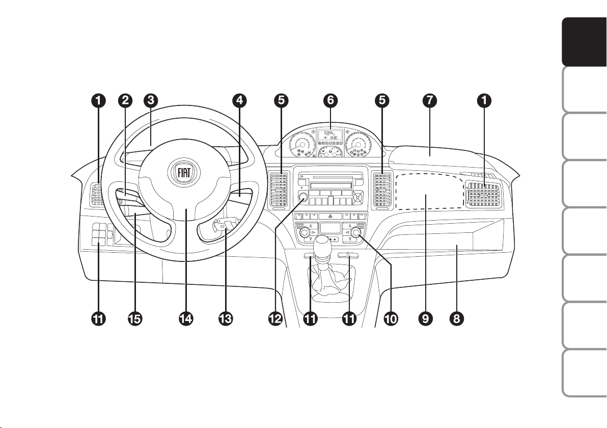
DASHBOARD
The presence and position of the controls, instruments and gauges may vary depending on the version.
There are several solutions for the central upper and lower console according to the chosen customisations: see the following figures.
F0R0734m
Fig. 1
1. Side air vents - 2. Left stalk- 3. Left upper box - 4. Right stalk - 5. Central air vents - 6. Instrument panel - 7. Upper right box
containing passenger side airbag switch - 8. Oddment compartment 9 Passenger airbag - 10. HVAC controls - 11. Control buttons
12 Sound system (where provided) - 13. Ignition switch - 14. Driver airbag - 15. Cruise control (where provided).
DASHBOARD
AND CONTROLS
SAFETY
STARTING
AND DRIVING
WARNING
MESSAGES
LIGHTS AND
IN AN
EMERGENCY
AND CARE
MAINTENANCE
TECHNICAL
SPECIFICATIONS
INDEX
ALPHABETICAL
5
Page 7
DASHBOARD
AND CONTROLS
SAFETY
STARTING
AND DRIVING
WARNING
MESSAGES
LIGHTS AND
IN AN
EMERGENCY
AND CARE
MAINTENANCE
TECHNICAL
SPECIFICATIONS
INDEX
ALPHABETICAL
6
fig. 2
fig. 3
F0H0231m
F0H0232m
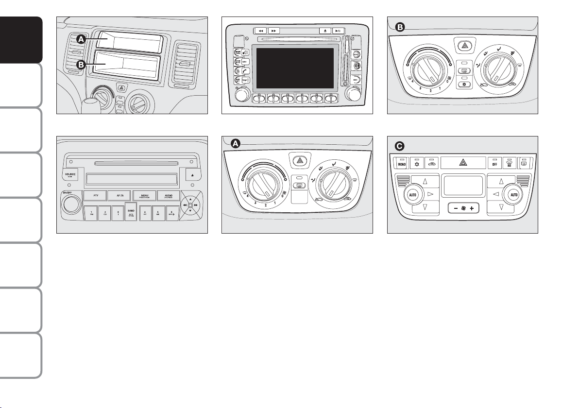
Upper central console:
❒ with fixed oddment compartment A
and extractable component (DIN) B
fig. 2 for installing the sound system;
❒ with sound system fig. 3.
❒ with Connect Nav+ fig. 4.
fig. 4
fig. 5
F0H0735m
F0H0233m
Lower central console:
❒ with heater A-fig. 5;
❒ with manual climate control system
B-fig. 6;
fig. 6
fig. 7
F0H0234m
F0H0235m
❒ with two-zone automatic climate con-
trol system C-fig. 7.
Page 8
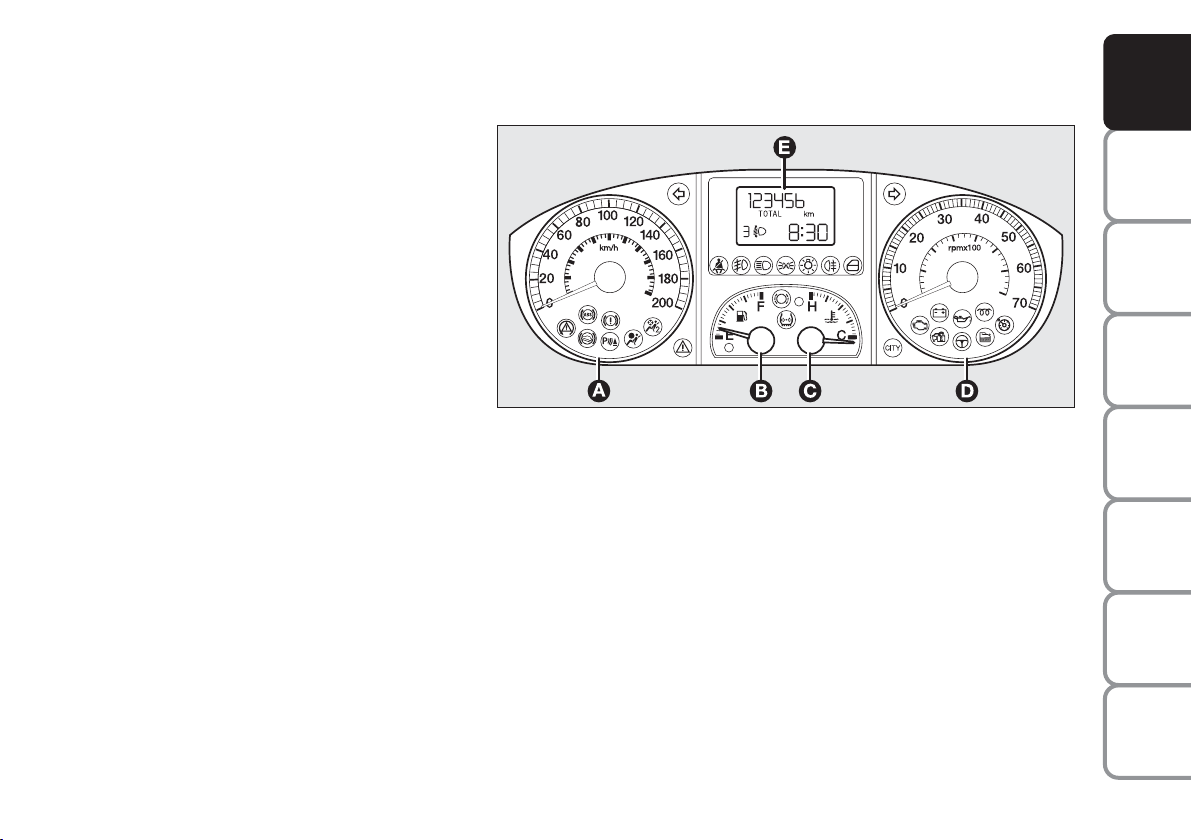
INSTRUMENT PANEL
Modal fig. 8
A – Speedometer
B – Fuel level gauge with reserve warning
light
C – Engine coolant temperature gauge and
excessive temperature warning light
D –Rev counter
E – Multifunction display
DASHBOARD
AND CONTROLS
SAFETY
STARTING
AND DRIVING
cm Warning lights for Multijet ver-
sions only
fig. 8
F0H0706m
WARNING
MESSAGES
LIGHTS AND
IN AN
EMERGENCY
AND CARE
MAINTENANCE
TECHNICAL
SPECIFICATIONS
INDEX
ALPHABETICAL
7
Page 9
DASHBOARD
AND CONTROLS
SAFETY
STARTING
AND DRIVING
WARNING
MESSAGES
LIGHTS AND
IN AN
EMERGENCY
AND CARE
MAINTENANCE
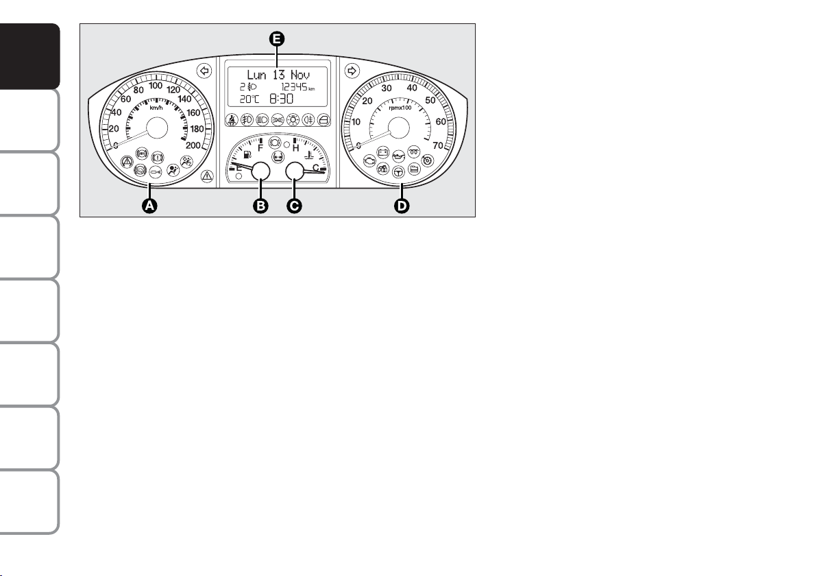
fig. 9
Comfort fig. 9
A – Speedometer
B – Fuel level gauge with reserve warning light
C – Engine coolant temperature gauge and
excessive temperature warning light
D – Rev counter
E – Reconfigurable multifunctional display
cm Warning lights for Multijet ver-
sions only
F0H0707m
TECHNICAL
SPECIFICATIONS
INDEX
ALPHABETICAL
8
Page 10
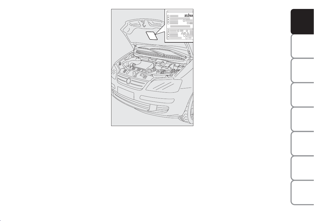
SYMBOLS
THE FIAT CODE SYSTEM
Special coloured labels have been attached
near or actually on some of the components of your car. These labels bear symbols that remind you of the precautions
to be taken as regards that particular component.
The plate summarising the symbols used
can be found under the bonnet fig. 10.
fig. 10
F0H0012m
This is an electrical engine locking system
which increases protection from attempted theft of the car. It is automatically
activated when the ignition key is extracted.
Each key contains an electronic device
which modulates the signal emitted during ignition by an antenna incorporated in
the ignition device. This signal is the ‘password’ which changes at each ignition and
which the control unit uses to recognise
the key and enable ignition.
DASHBOARD
AND CONTROLS
SAFETY
STARTING
AND DRIVING
WARNING
MESSAGES
LIGHTS AND
IN AN
EMERGENCY
AND CARE
MAINTENANCE
TECHNICAL
SPECIFICATIONS
INDEX
ALPHABETICAL
9
Page 11
DASHBOARD
AND CONTROLS
SAFETY
STARTING
AND DRIVING
WARNING
MESSAGES
LIGHTS AND
IN AN
EMERGENCY
AND CARE
MAINTENANCE
OPERATION
Each time the vehicle is started turning the
ignition key to MAR, the Fiat CODE system control unit sends a recognition code
to the engine control unit to deactivate
the inhibitor.
The code is sent only if the Fiat CODE
system control unit has recognised the
code transmitted from the key.
Each time the ignition key is turned to
STOP, the Fiat CODE system deactivates
the functions of the engine electronic control unit.
If the code has not been recognised correctly, the warning light
turns on on
Y
the display.
In this case, turn the key to STOP and
then back to MAR; try with the other
keys provided if the problem persists.
Contact a Fiat Dealership if you still cannot start the engine.
IMPORTANT Each key has its own code
which must be stored by the system ECU.
Contact the Fiat Dealership to have new
keys (up to eight) stored with the code.
Warning light
Y
coming on when driving
❒
If the warning light Yturns on, this
means that the system is running a selftest (for example for a voltage drop).
If the fault persists, contact a Fiat Dealership.
The electronic components
inside the key may be damaged if the key is submitted to
sharp knocks.
KEY KIT AND DOOR
LOCKING SYSTEM
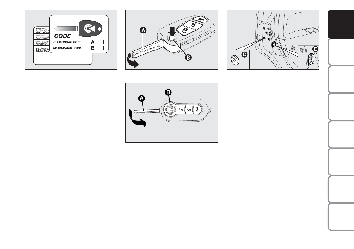
CODE CARD
(optional, for versions/market
where provided) fig. 11
The car is delivered the keys and a CODE
card which bears the following information:
❒
the electronic code A;
❒
the mechanical key code B to be given to the Fiat Dealership when ordering duplicate keys.
IMPORTANT In order to ensure complete efficiency of the electronic devices
inside the keys, they should never be exposed to direct sunlight.
All the keys and the CODE
card must be handed over to
the new owner when selling
the car.
TECHNICAL
SPECIFICATIONS
INDEX
ALPHABETICAL
10
Page 12
DASHBOARD
AND CONTROLS
SAFETY
fig. 11
F0H0700m
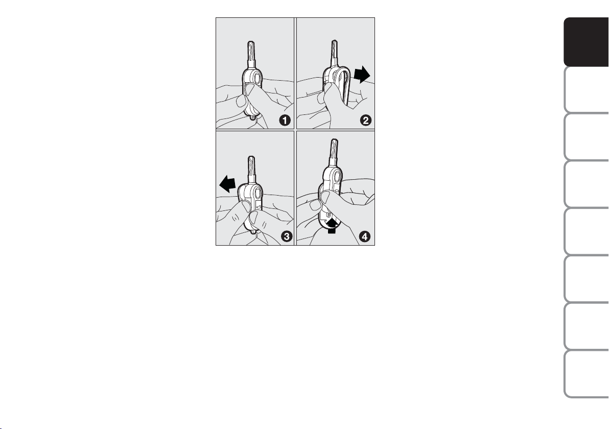
MAIN KEY WITH REMOTE
CONTROL fig. 12
The metal insert of the key A retracts into the grip.
The key operates:
❒
the ignition switch;
❒
the door lock on drive side;
❒
operation of the emergency front and
rear door lock release system D-fig.
13 from the outside for use the electric system is not working (e.g. flat battery);
❒
operation of the child lock Eon rear
doors.
fig. 12a
fig. 12b (where provided)
F0H0701m
F0H0767m
Press button B-fig. 12 to open the metallic part A.
To insert the metallic part A in the grip:
❒
hold button B pressed
❒
move the metallic part A
fig. 13
❒
release button B and then turn the
metal insert A until hearing the proper locking click.
Button
Ë
is used for unlocking the doors,
the tailgate and the fuel flap.
Button
Á is used for locking the doors,
the tailgate and the fuel flap.
Button
R
is used for remote opening
the tailgate.
F0H0246m
STARTING
AND DRIVING
WARNING
LIGHTS AND
IN AN
EMERGENCY
AND CARE
MAINTENANCE
TECHNICAL
SPECIFICATIONS
INDEX
ALPHABETICAL
11
MESSAGES
Page 13
DASHBOARD
AND CONTROLS
SAFETY
STARTING
AND DRIVING
WARNING
MESSAGES
LIGHTS AND
IN AN
EMERGENCY
AND CARE
MAINTENANCE
IMPORTANT Powerful radio transmissions not related to the car (e.g. mobile
phones, amateur radios, etc.) may interfere with the frequency of the remote
control. Remote control operation may
be impaired.
WARNING
Only press button B-fig. 12
with the key away from your
body, specifically from your eyes and
from objects which could get damaged (e.g. your clothes). Do not leave
the key unattended, because someone, a child especially, may accidentally press the button while handling
the key.
Unlocking the doors and the
tailgate
Press button
Ë
briefly: this will release the
doors, the tailgate, the fuel flap; the internal ceiling light will come on and the direction indicators will blink twice.
The doors are automatically unlocked
when the fuel inertia switch trips.
IMPORTANT Powerful radio transmissions not related to the car (e.g. mobile
phones, amateur radios, etc.) may interfere with the frequency of the remote
control. Remote control operation may
be impaired.
Locking the doors and the tailgate
Press button
Ábriefly: this will release the
doors, the tailgate, the fuel flap; the internal ceiling light will come on and the direction indicators will blink twice.
fig. 14
F0H0703m
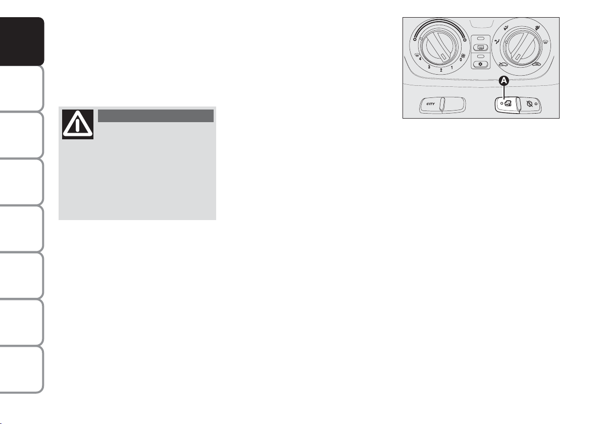
Deterrent LED indications
When locking the doors, the deterrent
LED on the button A-fig. 14 lights up for
about 3 seconds and than starts flashing
(deterrence function). Once doors are
locked, if one or more doors or the tailgate are not closed correctly, the led and
direction indicators start flashing quickly.
IMPORTANT Powerful radio transmissions not related to the car (e.g. mobile
phones, amateur radios, etc.) may interfere with the frequency of the remote
control. Remote control operation may
be impaired.
TECHNICAL
SPECIFICATIONS
INDEX
ALPHABETICAL
12
Page 14
Opening the tailgate with the
remote control
Hold button
R
pressed to unlock
(open) the tailgate. The direction indicators will blink twice when the tailgate is
opened.
IMPORTANT Powerful radio transmissions not related to the car (e.g. mobile
phones, amateur radios, etc.) may interfere with the frequency of the remote
control. Remote control operation may
be impaired.
Electrical closure from inside
fig. 14
With the doors closed, press button A on
the central dashboard to lock (LED on) or
unlock (LED off) the doors.
IMPORTANT If the door is not correctly closed or if a fault is present in the system, the door locking device from inside
the car will not work.
The device will resume normal operation
after removing the cause of the fault.
fig. 15a
F0H0704m
Only the doors used to get
out of the car will be unlocked if the door lock button
inside the car is pressed by
mistake. The tailgate will remain
locked. Press the lock/unlock buttons
to realign the system.
fig. 15b (where provided)
F0H0768m
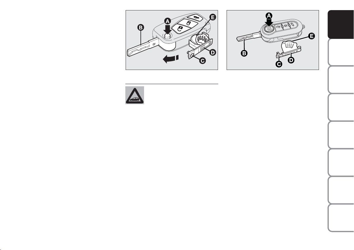
Replacing the battery of the key
with remote control Fig. 15
To replace the battery, proceed as follows:
❒
press button A and open the metal insert B;
❒
turn the screw C to using a fine bit
screwdriver;
❒
take out the battery case D and replace the battery E respecting its polarity;
❒
refit the battery case D inside the key
and lock it by turning the screw C.
DASHBOARD
AND CONTROLS
SAFETY
STARTING
AND DRIVING
WARNING
MESSAGES
LIGHTS AND
IN AN
EMERGENCY
AND CARE
MAINTENANCE
TECHNICAL
SPECIFICATIONS
INDEX
ALPHABETICAL
13
Page 15
Request for additional remote
controls
DASHBOARD
The system acknowledges up to 8 remote
controls. Should a new remote control be
AND CONTROLS
necessary, contact a Fiat Dealership, taking with you the CODE card, a personal
identity document and the car’s owner-
SAFETY
ship documents.
STARTING
AND DRIVING
WARNING
MESSAGES
LIGHTS AND
IN AN
EMERGENCY
AND CARE
MAINTENANCE
TECHNICAL
SPECIFICATIONS
INDEX
ALPHABETICAL
14
Used batteries are harmful to
the environment. They should
be disposed of as specified by
law in the special containers
provided, or take them to the Fiat
Dealership, which will deal with their
disposal.
fig. 16
F0H0705m
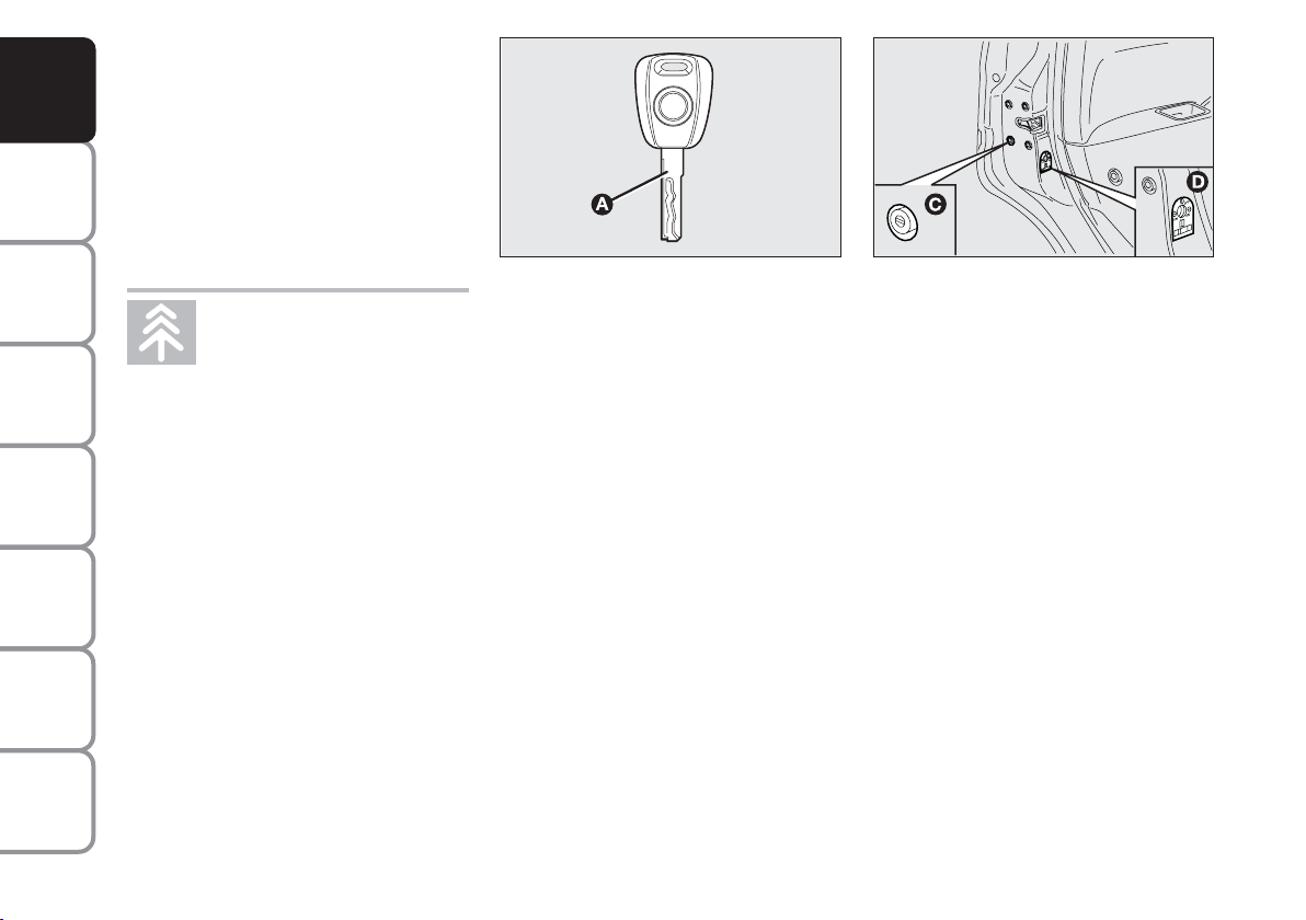
MECHANICAL KEY
(SPARE)
The metal insert of the key E-fig. 16 is
fixed.
The key operates:
❒
the ignition switch;
❒
the door lock on drive side;
fig. 17
❒
operation of the door safety device
C-fig. 17 from the outside for use the
electric system is not working (e.g. flat
battery);
❒
operation of the child lock D-fig. 17
on rear doors.
F0H0322m
Page 16
CHANGING THE REMOTE
CONTROL COVER fig. 18
(where provided)
Proceed as shown in the figure to replace
the remove control cover.
fig. 18
F0H0769m
DASHBOARD
AND CONTROLS
SAFETY
STARTING
AND DRIVING
WARNING
MESSAGES
LIGHTS AND
IN AN
EMERGENCY
AND CARE
MAINTENANCE
TECHNICAL
SPECIFICATIONS
INDEX
ALPHABETICAL
15
Page 17

The main functions that can be activated with the keys (with or without remote control) are the following:
DASHBOARD
AND CONTROLS
SAFETY
STARTING
AND DRIVING
WARNING
MESSAGES
LIGHTS AND
IN AN
EMERGENCY
AND CARE
MAINTENANCE
TECHNICAL
SPECIFICATIONS
Type of key
Spare mechanical
key
Main key
with remote control
Direction
indicators flashing (only for
key with remote control)
Deterrence led
Press button Ë to open the fuel flap.
Unlocking the doors
Turn key anticlockwise
(driver’s side)
Turn key anticlockwise
(driver’s side)
Press briefly button Ë
2 blinks
Off
Door closing form the outside
Turn key clockwise
(driver’s side)
Turn key clockwise
(driver’s side)
Press button Á
briefly:
blinks once
On fixed for approximately three
seconds followed by
deterrent blinking
Release tailgate lock
Press button R
2 blinks
Deterrent blink
INDEX
ALPHABETICAL
16
Page 18
WARNING
Operation of the child lock
A is only guaranteed if the
lock is turned and snaps into horizontal position (1).
DASHBOARD
AND CONTROLS
SAFETY
fig. 19
F0H0101m
CHILD LOCK fig. 19
To prevent opening the rear doors from
the inside.
This device can be engaged only with rear
doors open.
❒
position 1 - device on (door locked);
❒
position 2 - device off (door can be
opened from the passenger’s compartment).
The device A stays on even if the doors
are unlocked by the centralised system.
IMPORTANT Always use this device
when transporting children.
IMPORTANT After engaging the child lock
on both rear doors, check for proper engagement by trying to open a rear door
with the internal handle.
WARNING
Release of the child lock A is
only guaranteed if the lock is
turned and snaps into vertical position (2).
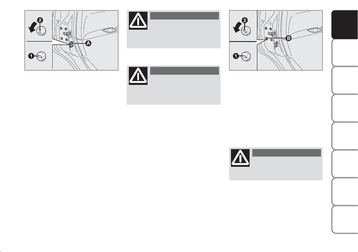
EMERGENCY DOOR
UNLOCKING DEVICE FROM
THE OUTSIDE fig. 20
The doors are provided with a device for
locking all the door using the lock in case
of a power fault.
Proceed as follows to lock the doors:
❒
insert the ignition key in lock B
❒
turn the device to position 1 and close
the door.
fig. 20
To open the doors:
❒
insert the key in the lock on driver’s
side and turn it anticlockwise
❒
open the driver’s door
❒
operate the door levers from the inside for the remaining doors.
WARNING
Do not operate the child
lock and the door handle at
the same time.
F0H0247m
STARTING
AND DRIVING
WARNING
LIGHTS AND
IN AN
EMERGENCY
AND CARE
MAINTENANCE
TECHNICAL
SPECIFICATIONS
INDEX
ALPHABETICAL
17
MESSAGES
Page 19
DASHBOARD
AND CONTROLS
SAFETY
STARTING
AND DRIVING
WARNING
MESSAGES
LIGHTS AND
IN AN
EMERGENCY
AND CARE
MAINTENANCE
TECHNICAL
SPECIFICATIONS
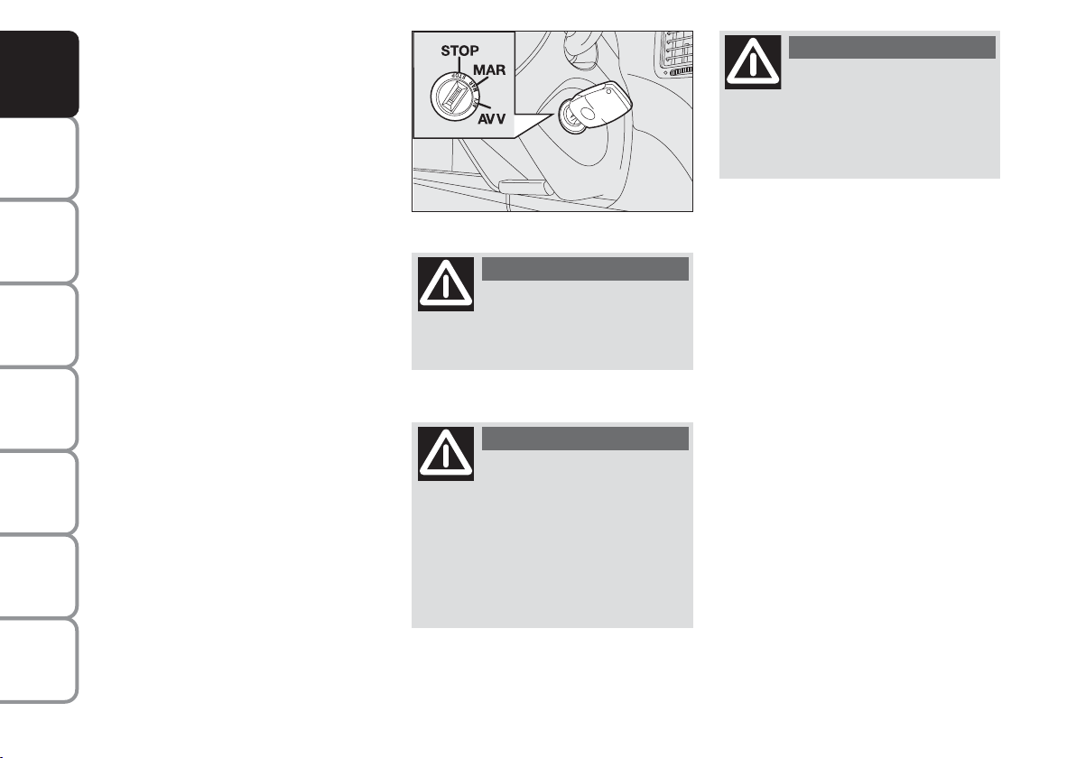
IGNITION DEVICE
The key can be turned to 3 different positions fig. 21:
❒
STOP: engine off, key extractable,
steering locked. Some electric devices
(e.g. sound system, central door locking system, etc.) may work.
❒
MAR: driving position. All electrical
devices work regularly.
❒
AVV: engine starting (unstable position).
The ignition switch is fitted with a safety
system that, in the event the engine is not
started, turns back the ignition key to
STOP before repeating the starting operation.
fig. 21
F0H0021m
WARNING
If the ignition device is tam-
pered with (e.g.: attempted
theft), have it checked over by a Fiat
Dealership as soon as possible.
WARNING
Always remove the key when
you leave your car to prevent someone from accidentally operating the controls. Remember to
engage the handbrake. Engage first
gear if the car is parked uphill or reverse if the car is parked downhill.
Never leave children unattended in
the car.
WARNING
Never extract the key while
the car is moving. The steering wheel would lock automatically
as soon as the steering wheel is
turned. This also applies to when the
car is towed.
STEERING LOCK
Engagement
When the key is in position STOP, remove the key and turn the steering wheel
until it is locked.
Switching off
Rock the steering wheel slightly as you
turn the ignition key to MAR.
INDEX
ALPHABETICAL
18
Page 20
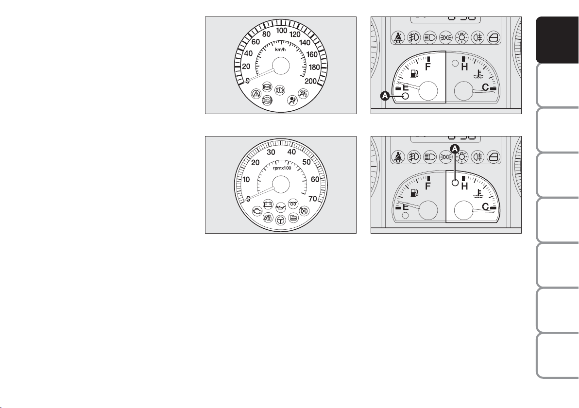
INSTRUMENTS
SPEEDOMETER Fig. 22
Indicates the car’s speed.
REV. COUNTER Fig. 23
This indicates the engine revolution per
minute.
IMPORTANT The electronic injection
control system gradually shuts off the flow
of fuel when the engine is ‘over-revving’
resulting in a gradual loss of engine power.
When the engine is idling, the rev counter
may indicate a gradual or sudden increase
of the speed.
This is normal and does not indicate a
fault. It may be caused, for example, by the
operation of the climate control system
or fan. In these case, a slow change in engine speed is used to protect the battery
charge.
FUEL LEVEL GAUGE Fig. 24
The instrument shows the litres of fuel
contained in the tank (see the “Refuelling”
paragraph for a description).
fig. 22
fig. 23
F0H0708m
F0H0022m
The reserve warning light A turns on to
indicate that approximately 6 litres of fuel are left in the tank. lack of fuel supply
could damage the catalyser.
fig. 24
fig. 25
F0H0023m
F0H0024m
ENGINE COOLANT
TEMPERATURE GAUGE fig. 25
Warning light A indicates overheating of
the engine coolant. In this case, stop the
engine and contact a Fiat dealer.
DASHBOARD
AND CONTROLS
SAFETY
STARTING
AND DRIVING
WARNING
MESSAGES
LIGHTS AND
IN AN
EMERGENCY
AND CARE
MAINTENANCE
TECHNICAL
SPECIFICATIONS
INDEX
ALPHABETICAL
19
Page 21
DASHBOARD
AND CONTROLS
SAFETY
STARTING
AND DRIVING
WARNING
MESSAGES
LIGHTS AND
IN AN
EMERGENCY
AND CARE
MAINTENANCE
TECHNICAL
SPECIFICATIONS
This shows the temperature of the engine
coolant fluid and starts working when the
fluid temperature exceeds approx. 50°C
circa. In normal conditions, the needle may
point to different positions according to
use and the engine cooling system management.
IMPORTANT The needle will point to the
lowest value of the scale (low temperature) and warning light A will light up to
indicate a fault in the system. Go to a Fiat Dealership to have the system checked.
If the needle reaches the red
area, stop the engine immediately and contact a Fiat
Dealership.
MULTIFUNCTIONAL
DISPLAY
(on two-line
modal panel)
The car can be equipped with the multifunction display for showing useful information necessary when driving according
to settings.
fig. 26
F0H0782m
INFORMATION ON
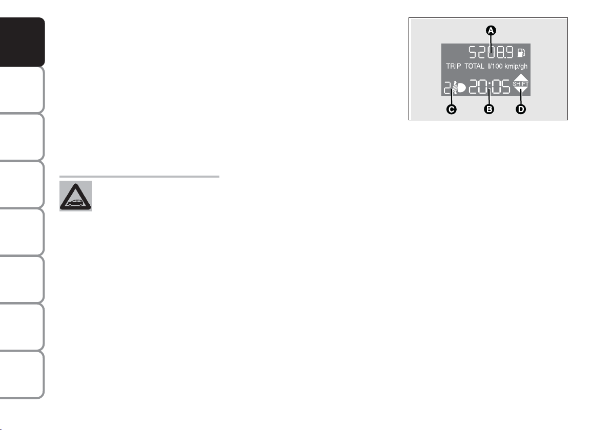
“STANDARD” SCREEN fig. 26
The standard screen shows the following
information:
A Odometer (kilometres or miles trav-
elled)
B Clock (always displayed, even with key
extract and front doors closed)
C Headlight adjustment (only with
dipped beam headlights on)
D Gear shift suggestion.
Note. When opening one of the front
doors, the display turns on and shows the
clock and the kilometres or miles covered
for a few seconds.
INDEX
ALPHABETICAL
20
Page 22
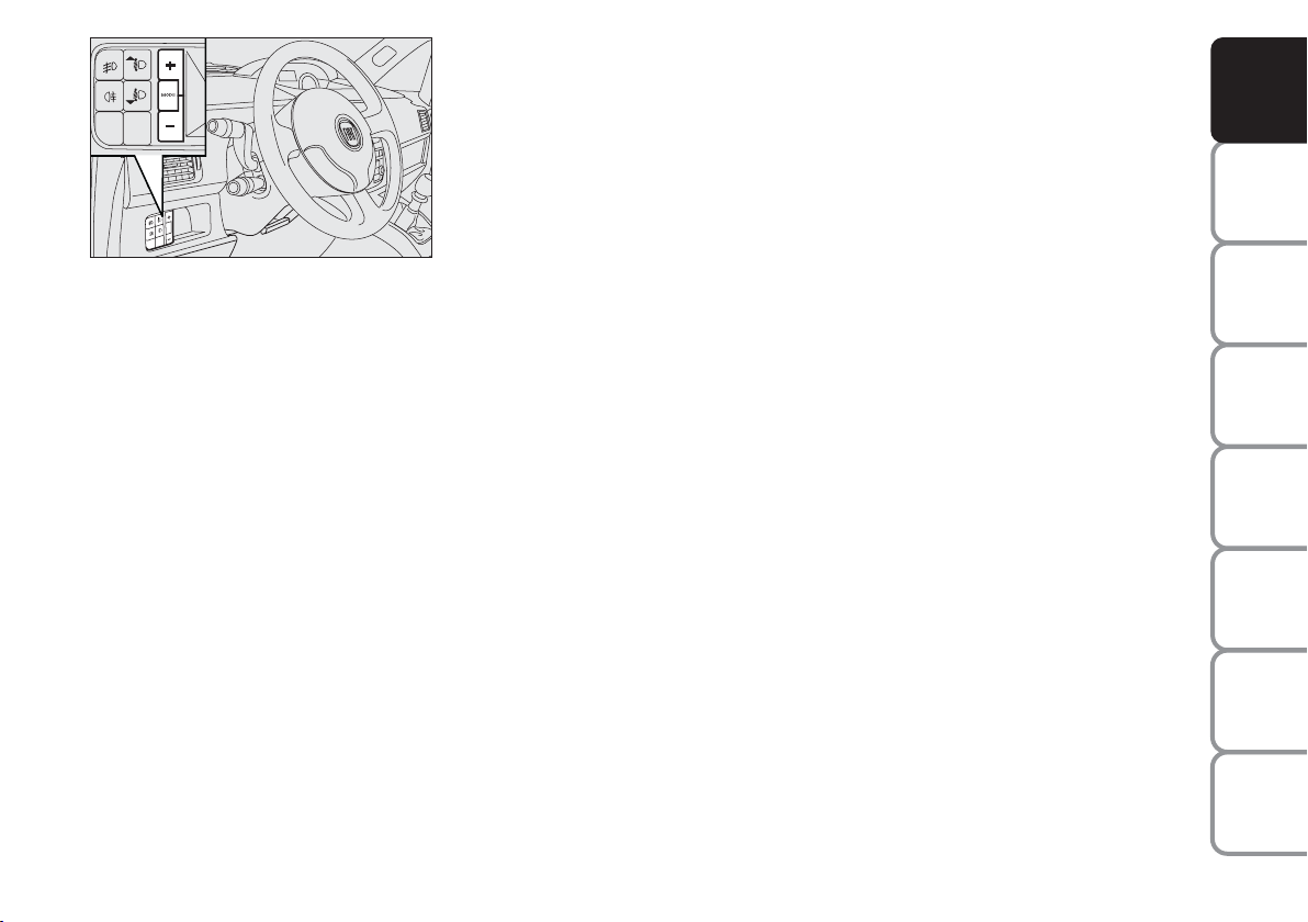
fig. 27
F0H0736m
CONTROL BUTTONS fig. 27
+
To scroll the menu and the next options or to increase the displayed value.
MODE Press briefly to access the menu
and/or go to next screen or to
confirm the required menu option.
Hold pressed to go back to the
standard screen.
–
To scroll the menu and the previous
options or to decrease the displayed
value.
Note Buttons + and – activate different
functions according to the following situations.
SET-UP MENU
The “Set-up Menu” is used for the following adjustments and/or settings:
❒
SETTING THE CLOCK
❒
SETTING THE BUZZER VOLUME
❒
SETTING THE SPEED LIMIT
❒
SETTING THE UNIT OF MEASUREMENT.
Setting the clock
The clock is set to 24 hours when the car
is delivered.
Proceed as follows to set the required
time:
❒
repeatedly press MODE to display
“Hour”;
❒
press + to increase one minute;
❒
press – to decrease one minute;
Hold buttons + or – pressed for a few
seconds to run the clock forwards or
backwards rapidly until the buttons are released.
❒
Hold button MODE pressed for
longer than two seconds to confirm
the change made to the time.
Setting the buzzer volume
To set the desired volume, proceed as follows:
❒
repeatedly press MODE to display
“bUZZ“;
❒
press + to increase the volume;
❒
press –to decrease the volume;
❒
Hold button MODE pressed for
longer than two seconds to confirm
the change made.
Setting the speed limit
A speed limit can be set and the system
will inform the drive when the limit is exceeded by means of an indication on the
display and the buzzer. Proceed as follows
to set:
This function is “OFF“ when the car is
delivered.
DASHBOARD
AND CONTROLS
SAFETY
STARTING
AND DRIVING
WARNING
MESSAGES
LIGHTS AND
IN AN
EMERGENCY
AND CARE
MAINTENANCE
TECHNICAL
SPECIFICATIONS
INDEX
ALPHABETICAL
21
Page 23
DASHBOARD
AND CONTROLS
SAFETY
STARTING
AND DRIVING
WARNING
MESSAGES
LIGHTS AND
IN AN
EMERGENCY
AND CARE
MAINTENANCE
Proceed as follows to select:
❒
repeatedly press MODE to display
“SPEEd“;
❒
press + to increase the value corresponding to speed (the maximum limit is 250 km/h);
❒
press – to decrease the value corresponding to speed (the limit is 30
km/h under which it switches to
“OFF”);
❒
to confirm the setting, hold button
MODE pressed for longer than two
seconds.
Setting the unit of measurement
Proceed as follows to set the required unit
of measurement (kilometres or miles):
❒
repeatedly press MODE to display“Unit”;
❒
press button + or – to change the unit
of measurement;
❒
to confirm the setting, hold button
MODE pressed for longer than two
seconds.
Fuel inertia
switch tripped indication
The indication appears automatically if the
fuel inertia switch trips follow a collision
of considerable severity.
The switch cuts off fuel feed.
See the “Fuel inertia switch” chapter for
more information.
WARNING
If after the “FPSon” message
appears, you smell fuel or
see leaks from the fuel system, do not
reset the switch to avoid fine risk.
TECHNICAL
SPECIFICATIONS
INDEX
ALPHABETICAL
22
Page 24
MULTIFUNCTIONAL
DISPLAY
(on three-line comfort
panel)
The car can be equipped with the multifunction display for showing useful information necessary when driving according
to settings.
INFORMATION ON
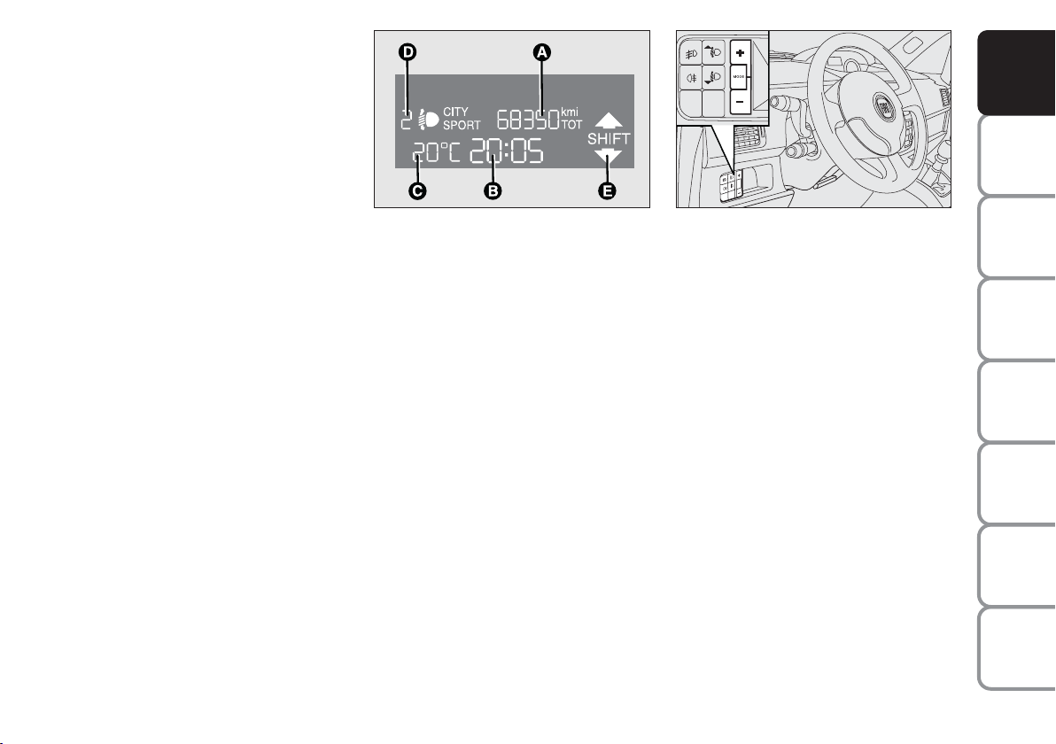
“STANDARD” SCREEN fig. 28
The standard screen shows the following
information:
A Date / Odometer (covered km or
miles).
B Clock (always displayed, even with
ignition key removed and front doors
closed).
C External temperature
fig. 28
F0H0781m
D Headlight alignment position (only
with dipped beam headlights on)
E Gear shift suggestion.
Note. When opening one of the front
doors, the display turns on and shows the
clock and the kilometres or miles covered
for a few seconds.
fig. 29
F0H0736m
CONTROL BUTTONS fig. 29
+
To scroll the menu and the next options or to increase the displayed value.
MODE Press briefly to access the menu
and/or go to next screen or to
confirm the required menu option.
Hold pressed to go back to the
standard screen.
–
To scroll the menu and the previous
options or to decrease the displayed
value.
Note Buttons + and – activate different
functions according to the following situations.
DASHBOARD
AND CONTROLS
SAFETY
STARTING
AND DRIVING
WARNING
MESSAGES
LIGHTS AND
IN AN
EMERGENCY
AND CARE
MAINTENANCE
TECHNICAL
SPECIFICATIONS
INDEX
ALPHABETICAL
23
Page 25

DASHBOARD
AND CONTROLS
SAFETY
STARTING
AND DRIVING
WARNING
MESSAGES
LIGHTS AND
IN AN
EMERGENCY
AND CARE
MAINTENANCE
Headlight adjustment (only
with dipped beam headlights on)
– when the standard page is displayed, this
is used to adjust the headlights (see the
“Headlights” paragraph in this chapter).
Setup menu
– for scrolling the menu up and down;
– to increase or decrease values during
settings.
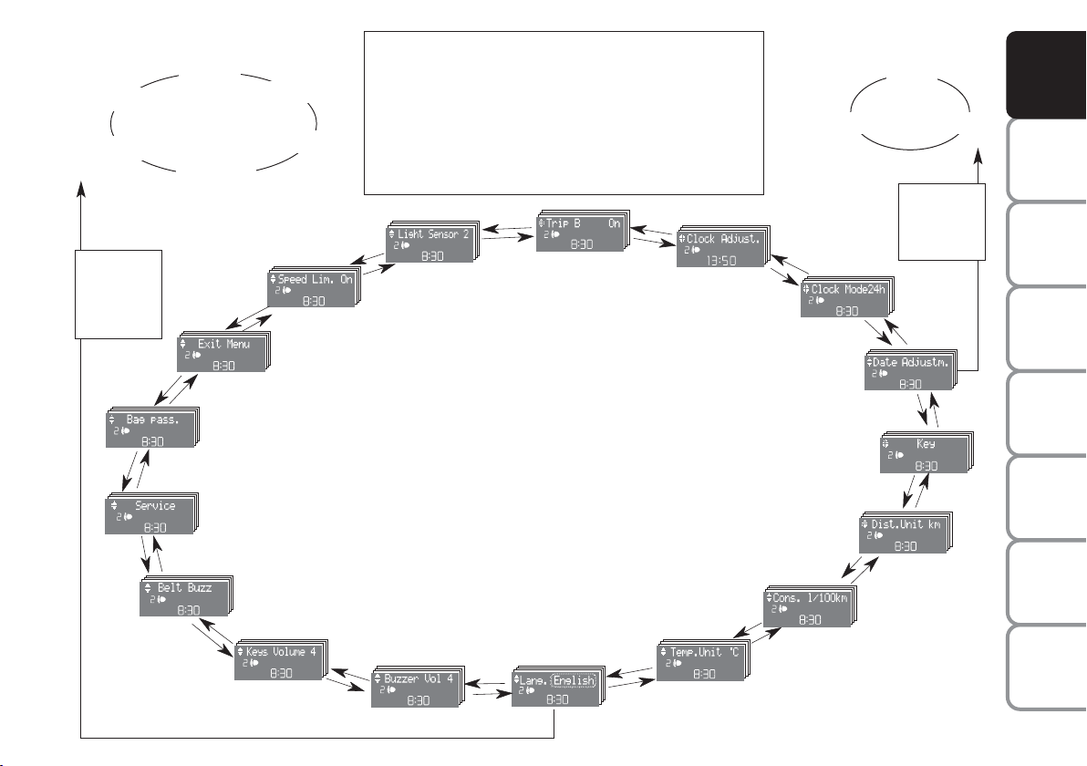
SETUP MENU Fig. 30
The menu comprises a series of functions
arranged in a “circular fashion” which can
be selected through buttons + and – to
access the different select operations and
settings (setup) given in the following paragraphs.
The setup menu is activated by pressing
briefly button MODE.
Single presses on buttons + and –will
scroll the setup menu options.
Management modes differ with each other according to the characteristic of the
option selected.
NOTE Only the following functions can
be adjusted/set on the instrument panel
display if the Connect Nav+ system is present: “Lights”, “Speed limit”, “Light sensor” (where provided), “Belt buzzer” and
“Passenger airbag”. The other functions
are shown on the Connect Nav+ system
display. Set and adjustment them there.
Selecting a menu option
– briefly press button MODE to select
the menu option that needs to be
changed.
– press buttons + and – (by single presses) to select the new setting;
– briefly press button MODE to store
the new setting and at the same time go
back to the previously selected menu option.
Selecting “Set Date” and “Set time”:
– briefly press button MODE to select
the first value to be changed (e.g. hours
/minutes or year / month / day).
– press buttons + and – (by single presses) to select the new setting;
– briefly press button MODE to store the
new setting and go to the next setup menu
option: if this is the last one you will go
back to the previously selected option of
the main menu.
Prolonged pressing of the button
MODE make it possible:
– quit set-up and to save only the changes
stored by the user (and confirmed by
pressing button MODE).
The setup menu environment is timed.
Only the changes saved by the user by
briefly pressing MODE) will be saved
when the menu is automatically closed.
TECHNICAL
SPECIFICATIONS
INDEX
ALPHABETICAL
24
Page 26
Example:
Italiano
Português
MODE
button
pressed
briefly
+
fig. 30
Example:
Deutsch
Français
+
–
English
Español
+
–
SPEED LIMIT
QUIT MENU
PASSENGER BAG
On the standard screen, briefly press MODE to start
browsing. Press + or – browse within the menu.
NOTE Only the short menu may be accessed for reasons of safety while the car is moving (“Brightness” and
“Speed Limit”). Stop the car to access the full menu. On
car equipped with Connect Nav+, many functions are displayed on the navigator readout.
+
–
LIGHT SENS.
+
–
TRIP B
+
–
ECE CLOCK
CLOCK MODE
+
–
SET DATE
KEY
Day
Year Month
MODE
button
pressed
briefly
–
+
–
+
DASHBOARD
AND CONTROLS
SAFETY
STARTING
AND DRIVING
WARNING
MESSAGES
LIGHTS AND
IN AN
EMERGENCY
–
–
+
SERVICE
–
+
BELT BUZZER
(*) (where provided)
–
+
BUTTON VOL.
+
BUZZER VOLUME
–
–
+
LANGUAGE
CONSUMPTION
TEMP. UNIT
–
+
–
F0H4279g
UNIT DIST.
–
+
(*) This function may only
be displayed after the SBR
system is deactivated by a
Fiat Dealership.
+
AND CARE
MAINTENANCE
TECHNICAL
SPECIFICATIONS
INDEX
ALPHABETICAL
25
Page 27

DASHBOARD
AND CONTROLS
SAFETY
STARTING
AND DRIVING
WARNING
MESSAGES
LIGHTS AND
IN AN
EMERGENCY
AND CARE
MAINTENANCE
Speed limit
This function is used to set the car speed
limit (km/h or mph); the driver is immediately alerted when this limit is exceeded
(see section “Warning lights and messages”).
To set the speed limit, proceed as follows:
– briefly press MODE, the message
(speed limit) will appear on the display.
– press button + or – to select speed limit activation (On) or deactivation (Off);
– if the function has been activated (On),
press buttons + or – to select the required speed limit and then press MODE
to confirm.
Note The speed may be set in the range
from 30 to 250 km/h, or from 20 to 155
mph according to the previously chosen
unit (see “Setting the distance unit”) described below. The setting will increase/decrease by five units each time
button + / – is pressed. Hold button + /
– pressed to increase/decrease the setting
rapidly. When the desired value is
reached, end adjustment with a single
press.
– briefly press button MODE to go back
to the menu screen or press the button
for a prolonged time to go back to the
standard screen without storing the settings.
To cancel the setting, proceed as follows:
– briefly press button MODE: (On) will
flash on the display;
– press button +: (Off) will flash on the
display;
– briefly press button MODE to go back
to the menu screen or press the button
for a prolonged time to go back to the
standard screen without storing the settings.
TECHNICAL
SPECIFICATIONS
INDEX
ALPHABETICAL
26
Page 28

Adjusting the automatic headlight
sensor sensitivity (light sensor)
(where fitted)
This function is used to adjust the dusk
sensor sensitivity to three levels (level 1
= minimum, level 2 = medium, level 3 =
maximum); higher the sensitivity, lower
the quantity of external light needed to
switch the headlights on. The device is set
to level “2” when the car is delivered.
Proceed as follows to set:
– briefly press button MODE, the previously set level will flash on the display;
– press button + or – for setting;
– briefly press button MODE to go back
to the menu screen or press the button
for a prolonged time to go back to the
standard screen without storing the settings.
Turning Trip B on/off (Trip B)
This function allows display of Trip B (partial trip) to be activated (On) or deactivated (Off).
For further information see “Trip computer”.
Proceed as follows to turn on and off:
– briefly press MODE ON or OFF flashes on the display (according to the previous setting);
– press button + or – for setting;
– briefly press button MODE to go back
to the menu screen or press the button
for a prolonged time to go back to the
standard screen without storing the settings.
Setting the clock
(Set clock)
This function is used to set the clock.
To carry out the adjustment, proceed as
follows:
– briefly press button MODE: the
“hours” will flash on the display;
– press button + or – to set;
– briefly press button MODE: “minutes”
will start flashing on the display;
– press button + or – to set.
Note The setting will increase or decrease
by one unit each time + or – is pressed.
Hold the button pressed to increase/decrease the setting rapidly.
When the desired value is reached, end
adjustment with a single press.
– briefly press button MODE to go back
to the menu screen or press the button
for a prolonged time to go back to the
standard screen without storing the settings.
DASHBOARD
AND CONTROLS
SAFETY
STARTING
AND DRIVING
WARNING
MESSAGES
LIGHTS AND
IN AN
EMERGENCY
AND CARE
MAINTENANCE
TECHNICAL
SPECIFICATIONS
INDEX
ALPHABETICAL
27
Page 29

DASHBOARD
AND CONTROLS
SAFETY
STARTING
AND DRIVING
WARNING
MESSAGES
LIGHTS AND
IN AN
EMERGENCY
AND CARE
MAINTENANCE
12h/24h clock mode
This function is used to select 12h or 24
h display.
To carry out the adjustment, proceed as
follows:
– briefly press MODE: either 12h or 24h
will start flashing on the display (according to the previous setting);
– press button + or – for setting;
– briefly press button MODE to go back
to the menu screen or press the button
for a prolonged time to go back to the
standard screen without storing the settings.
Set date
This function is used to set the date (year
– month – day).
Proceed as follows to update:
– briefly press button MODE: “year” will
start flashing on the display;
– press button + or – to set;
– briefly press button MODE: “day” will
start flashing on the display;
– press button + or – to set;
– briefly press button MODE: “day” will
start flashing on the display;
– press button + or – to set.
Note The setting will increase or decrease
by one unit each time + or – is pressed.
Hold the button pressed to increase/decrease the setting rapidly. When
the desired value is reached, end adjustment with a single press.
– briefly press button MODE to go back
to the menu screen or press the button
for a prolonged time to go back to the
standard screen without storing the settings.
Unlocking the doors and the
tailgate (key)
This function is used to: unlock the front
and rear doors, unlock the driver’s side
door or all the doors including the tailgate.
Proceed as follows to set:
– briefly press button MODE: “Open
doors”, “Open driver”, “Open all”;
– press button + or – to select. The selected item will blink.
– briefly press button MODE to go back
to the menu screen or press the button
for a prolonged time to go back to the
standard screen without storing the settings.
TECHNICAL
SPECIFICATIONS
INDEX
ALPHABETICAL
28
Page 30

“Distance” unit of measure
This function is used to set the unit of
measure for distance (kilometres or miles)
Proceed as follows to set the required
unit:
– briefly press MODE: (km) or (mi) will
start blinking on the display (according to
the previous setting);
– press button + or – for setting;
– briefly press button MODE to go back
to the menu screen or press the button
for a prolonged time to go back to the
standard screen without storing the settings.
“Consumption” unit of measure
This function is used to set the unit of
measure for fuel consumption (km/l, l/100
km or mpg) according to the unit of measure selected in the previous paragraph
(“Distance” unit of measure).
If the distance unit set is “km” the fuel consumption unit will be displayed in km/l or
l/100km. If the distance unit set is “mi” the
fuel consumption unit will be displayed in
“mpg”.
Proceed as follows to set:briefly press
MODE: km/l) or (l/100km) will start flashing on the display (according to the previous setting);
– press button + or – for setting;
– briefly press button MODE to go back
to the menu screen or press the button
for a prolonged time to go back to the
standard screen without storing the settings.
DASHBOARD
AND CONTROLS
SAFETY
STARTING
AND DRIVING
WARNING
MESSAGES
LIGHTS AND
IN AN
EMERGENCY
AND CARE
MAINTENANCE
TECHNICAL
SPECIFICATIONS
INDEX
ALPHABETICAL
29
Page 31

DASHBOARD
AND CONTROLS
SAFETY
STARTING
AND DRIVING
WARNING
MESSAGES
LIGHTS AND
IN AN
EMERGENCY
AND CARE
MAINTENANCE
“Temperature” unit of measure
This function is used to set the unit of
measure for distance (°C or °F)
Proceed as follows to set the required
unit:
– briefly press MODE: (°C) or (°F) will
start blinking on the display (according to
the previous setting);
– press button + or – for setting;
– briefly press button MODE to go back
to the menu screen or press the button
for a prolonged time to go back to the
standard screen without storing the settings.
Selecting the language
The messages may be displayed in the following languages: Italian, German, English,
Spanish, French, Portuguese.
To set the required language proceed as
follows:
– briefly press button MODE: the previously set “language” starts flashing on the
display;
– press button + or – for setting;
– briefly press button MODE to go back
to the menu screen or press the button
for a prolonged time to go back to the
standard screen without storing the settings.
Adjusting the failure/warning
buzzer volume
(Buzzer Volume)
This function allows the volume of the
buzzer which accompanies the display of
failures / warnings to be adjusted (8 levels). To set the desired volume, proceed
as follows:
– briefly press button MODE: the previously set volume “level” starts flashing on
the display;
– press button + or – to set;
– briefly press button MODE to go back
to the menu screen or press the button
for a prolonged time to go back to the
standard screen without storing the settings.
TECHNICAL
SPECIFICATIONS
INDEX
ALPHABETICAL
30
Page 32

Adjust the button volume
(Button Vol.)
This function is used to set the volume of
the roger-beep accompanying the activation of buttons MODE, + e – through 8
levels.
To set the desired volume, proceed as follows:
– briefly press button MODE: the previously set volume “level” starts flashing on
the display;
– press button + or – to set;
– briefly press button MODE to go back
to the menu screen or press the button
for a prolonged time to go back to the
standard screen without storing the settings.
S.B.R. buzzer reactivation (Belt
Buzzer) (where provided)
This function can be only displayed after a
Fiat Dealership has deactivated the S.B.R.
system (see paragraph “S.B.R. system” in
section “Safety devices”).
Scheduled Servicing (Service)
This function may be used to display information connected to proper car servicing in terms of kilometres or days.
This information can be consulted as follows:
–briefly press button MODE: service in
km or mi, according to previous setting,
will be displayed (see paragraph “Units”);
– press button + or – to set deadline in
days;
– briefly press button MODE to go back
to the menu screen or hold the button
pressed to go back to the standard screen.
Note The “Service Schedule” requires the
car to be services every 20,000 km (or
equivalent distance in miles) or once a
year. This message will appear automatically with key at MAR after 2,000 km (or
equivalent distance in miles) or 30 before
the deadline and will appear every 200 km
(or equivalent distance in miles) or 3 days.
The indications will appear more frequently where there are 200 km left. For
1.3 Multijet versions, refer to the “Service
Schedule” in the “Maintenance and care”
chapter for replacing the air cleaner, the
engine oil and the engine oil filter. The indication will appear in kilometres or miles
according to the settings. When the next
scheduled service operation is approaching, the message “Service” will appear on
the display followed by the number of kilometres or miles left when the key is
turned to MAR. The “Service Schedule”
information is provided with kilometres
(km)/miles (mi) or days (dd), according to
the deadline which appears first. Go to a
Fiat Dealership where the “Scheduled Service” operations will be performed and the
message will be reset.
DASHBOARD
AND CONTROLS
SAFETY
STARTING
AND DRIVING
WARNING
MESSAGES
LIGHTS AND
IN AN
EMERGENCY
AND CARE
MAINTENANCE
TECHNICAL
SPECIFICATIONS
INDEX
ALPHABETICAL
31
Page 33

DASHBOARD
AND CONTROLS
SAFETY
STARTING
AND DRIVING
WARNING
MESSAGES
LIGHTS AND
IN AN
EMERGENCY
AND CARE
MAINTENANCE
Activating/deactivating the
passenger front and side airbag
on/off
(where provided) (passenger bag)
This function shall be used to activate/deactivate the passenger’s airbag.
Proceed as follows:
❒
press MODE and after the message
(Bag pass Off) (deactivate) or (Bag
pass On) (activate) appears by pressing buttons + and –, press the
MODE button again;
❒
the confirmation request message will
be displayed;
❒
press buttons + or – to select (Yes)
(to confirm activation/deactivation) or
(No) (to abort);
❒
briefly press button MODE: the display shows a message confirming the
selected value. Now, go back to the
menu screen or press the button for
a prolonged time to go back to the
standard screen without storing the
settings.
F0H4272g
F0H4275g
F0H4276g
MODE
+
–
MODE
+
–
MODE
F0H4271g
+
–
F0H4273g
+
–
F0H4274g
F0H4276g
TECHNICAL
SPECIFICATIONS
INDEX
ALPHABETICAL
32
F0H4278g
F0H4277g
Page 34

Quit menu
This function closes the cycle of settings
listed in the menu screen.
Briefly press button MODE to go back to
the standard screen without storing the
settings.
Press button + to return to the first menu
option (Speed Limit).
TRIP COMPUTER (where
provided)
General information
The “Trip computer” is used to display information on car operation when the key
is turned to MAR. This function consists
of “General trip” for displaying the complete mission of the car and by “Trip B”,
for trips; this function is included in the
general trip information (as shown in fig.
32).
Both functions can be reset (to start a new
trip). The following data can be displayed
for “General Trip”:
– Range
– Distance travelled
– Average consumption
– Instant consumption
– Average speed
– Travel time (driving time).
“Trip B” may be used to display the figures
relating to:
– Distance travelled B
– Average consumption B
– Average speed B
– Travel time (driving time).
Note “Trip B” functions may be excluded (see “Trip B on”). “Range” and “Instantaneous consumption” cannot be reset.
DASHBOARD
AND CONTROLS
SAFETY
STARTING
AND DRIVING
WARNING
MESSAGES
LIGHTS AND
IN AN
EMERGENCY
AND CARE
MAINTENANCE
TECHNICAL
SPECIFICATIONS
INDEX
ALPHABETICAL
33
Page 35

DASHBOARD
AND CONTROLS
SAFETY
STARTING
AND DRIVING
WARNING
MESSAGES
LIGHTS AND
IN AN
EMERGENCY
AND CARE
MAINTENANCE
TECHNICAL
SPECIFICATIONS
Values displayed
Range
This indicates the indicative distance which
may be travelled with the fuel in the tank
assuming that driving conditions do not
change. The display will show the reading
“----“ when the following events take
place:
– range lower than 50 km (or 30 miles)
or fuel level less than 4 litres in the tank;
– car left parked with engine running for
a long time.
Distance travelled
This value shows the distance covered
from the start of the new mission.
Average consumption
This indicates the indicative average consumption from the start of the new mission.
Instant consumption
Indicates the fuel consumption. The value is constantly updated. The message
“----” will appear on the display if the car
is parked with the engine running.
Average speed
This shows the car average speed as a
function of the overall time elapsed since
the start of the new mission.Journey time
This value shows the time elapsed since
the start of the new mission.
IMPORTANT If information is not available, the message “----” will appear instead
of the Trip Computer values. Displaying
of the values will be resumed when normal operation is restored without resetting the values displayed before the problem nor starting a new mission.
TRIP button fig. 31
Button TRIP located on the top of the
right steering column stalk is used (with
ignition key at MAR) to display and reset the previously described values to start
a new mission:
– short push to display the different values
– long push to reset and then start a new
mission.
fig. 31
F0H0755m
New mission
The new mission begins after:– “manu-
al” resetting by the user, by pressing the
relevant button;
– “automatic” resetting, when the “Trip
distance” reaches 3999.9 km or 9999.9 km
(according to the type of display) or when
the “Travel time” reaches 99.59 (99 hours
and 59 minutes);
– after disconnecting/reconnecting the
battery.
IMPORTANT “General Trip” resets will
reset “Trip B” at the same time, while resetting “Trip B” will only reset the values of the trip B function.
INDEX
ALPHABETICAL
34
Page 36

Start trip procedure
With ignition key at MAR, press and keep button TRIP pressed for over 2 seconds to reset.
Quitting TRIP
The TRIP function shuts down automatically after displaying all the data. Alternatively, hold MODE pressed for longer than two
seconds.
GENERAL TRIP reset
End of complete mission
Start of new mission
˙
˙
Trip B reset
End of partial mission
Start of new partial mission
TRIP B
Reset TRIP B
˙
˙
End of partial mission
Start of new
partial mission
GENERAL TRIP
Reset TRIP B
TRIP B
End of partial mission
Start of new
partial mission
˙
TRIP B
˙
GENERAL TRIP reset
End of complete mission
Start of new mission
˙
˙
Reset TRIP B
End of partial mission
Start of new
partial mission
DASHBOARD
AND CONTROLS
SAFETY
STARTING
AND DRIVING
WARNING
MESSAGES
LIGHTS AND
IN AN
EMERGENCY
AND CARE
MAINTENANCE
TECHNICAL
SPECIFICATIONS
INDEX
ALPHABETICAL
35
Page 37

DASHBOARD
AND CONTROLS
SAFETY
STARTING
AND DRIVING
WARNING
MESSAGES
LIGHTS AND
IN AN
EMERGENCY
AND CARE
MAINTENANCE
ADJUSTING THE
STEERING WHEEL
The steering wheel can be adjusted in
height A-fig. 32 and in depth B.
To carry out the adjustment, proceed as
follows:
❒
release the lever by pulling it towards
the steering wheel (position 2);
❒
adjust the steering wheel as required;
❒
release the lever by pushing it forwards (position 1);
WARNING
Any adjustment of the steer-
ing wheel position must be
carried out only with the car stationary and the engine turned off.
Fig. 32
F0H0737m
WARNING
Under no circumstances
should aftermarket operations involving steering system or
steering column modifications (e.g.:
installation of anti-theft device) be
carried out that could badly affect
performance and safety. This also
causes the warranty to become null
and void and results in vehicle noncompliance with type-approval requirements.
ADJUSTING THE SEATS
FRONT SEATS
Fore/aft adjustment
Lift lever A-fig. 33 and push the seat forwards and backwards to reach the required position: your arms should rest on
the steering wheel rim while you are driving.
Check that the seat is locked well on the
guides by trying to push it forwards and
backwards.
Adjusting the height
(driver’s seat) (where provided)
Move lever
B-fig. 33
wards to achieve the required height.
IMPORTANT Sit in the driver’s seat with
the car not moving to adjust.
upwards or down-
TECHNICAL
SPECIFICATIONS
INDEX
ALPHABETICAL
36
Page 38

DASHBOARD
AND CONTROLS
SAFETY
fig. 33
F0H0041m
Adjusting backrest inclination
Operate the lever D-fig. 34 in the direction of the arrow, take the backrest to the
required position and then release it.
Lumbar adjustment
(where provided)
To adjust the support between back and
backrest, turn knob C-fig. 34 clockwise
to increase the lumbar support or anticlockwise to decrease it.
WARNING
Make sure that the seats are
correctly secured after mak-
ing the adjustments.
fig. 34
fig. 35
F0H0042m
F0H0043m
Armrest adjustment
(where provided) fig. 35
To use the armrest, move it from position
1 to position 2.
fig. 36
fig. 37
F0H0044m
F0H0045m
Arranging the passenger seat in
table position
Move the armrest (where provided) to
vertical position.
From the driver’s seat or from the rear
seats, operate the lever A-fig. 36 in the
direction of the arrow, fold the backrest
onto the cushion and then release it. In
this position, the backrest fig. 37 may be
used as a table.
STARTING
AND DRIVING
WARNING
LIGHTS AND
IN AN
EMERGENCY
AND CARE
MAINTENANCE
TECHNICAL
SPECIFICATIONS
INDEX
ALPHABETICAL
37
MESSAGES
Page 39

DASHBOARD
AND CONTROLS
SAFETY
STARTING
AND DRIVING
WARNING
MESSAGES
LIGHTS AND
IN AN
EMERGENCY
AND CARE
MAINTENANCE
TECHNICAL
SPECIFICATIONS
INDEX
ALPHABETICAL
38
fig. 38
F0H0046m
Arranging the driver’s seat
in table position
To arrange the driver’s seat in table position, remove the head restraint (see
“Extracting the head restraint” in the
“Head restraint” chapter) and proceed as
shown above.
Heated seats
(where provided)
Press buttons B-fig. 38 to heat the driver’s seat C and to heat the passenger’s
seat.
The LED in the button will light up when
heating is on.
fig. 39
F0H0047m
SLIDING REAR SEAT
Adjusting from inside the
passenger compartment
Lengthwise direction adjustment
fig. 39
Respectively lift the lever A or the lever
B to adjust the required seat portion, then
push the seat back or forwards.
Back rest angle adjustment
fig. 40
Push the lever C move the backrest to
position and then release it.
To prevent irregular operation: press the
lever C as far as it will go.
fig. 40
fig. 41
F0H0252m
F0H0253m
FIXED REAR SEATS
(where provided)
See the “Expanding the boot” paragraph
for how to fold the seat.
Adjusting from inside the boot
Lengthwise direction adjustment
fig. 41
Operate on handles F and G to adjust the
required seat portion by pushing the seat
forwards or backwards.
Page 40

DASHBOARD
AND CONTROLS
SAFETY
fig. 42
F0H0049m
WARNING
Make sure that the seats are
correctly secured after mak-
ing the adjustments.
Back rest angle adjustment
fig. 42
Operate lever A or lever B to adjust the
required backrest portion, take the backrest to position and then release.
Adjusting the central
unit from the inside
To move the backrest to the horizontal
position:
❒
operate the lever D-fig. 44 (one per
side)
❒
fully lower the central backrest
❒
release the lever.
fig. 43
F0H0051m
The cup holder A-fig. 43 (where provided) can be used when the central unit is
all down and the head restraint is removed
(as shown in the figure).
To arrange the central unit back in vertical position, operate lever D-fig. 44 again
(one on each side) and realign the unit
with the side backrests and make the safety clip E.
WARNING
After releasing the adjust-
ment lever, always check
that the seat is locked on the runners
by trying to move it back and forth. If
it is not locked, the seat may move
unexpectedly and make you loose
control of the car.
fig. 44
fig. 45
F0H0050m
F0H0249m
Ski compartment fig. 45
Lower the armrest to access the ski compartment.
The compartment may be used for transporting long items (e.g. skis). Insert the
item from the boot.
To access the compartment B lower the
central rear backrest A (as shown above)
STARTING
AND DRIVING
WARNING
LIGHTS AND
IN AN
EMERGENCY
AND CARE
MAINTENANCE
TECHNICAL
SPECIFICATIONS
INDEX
ALPHABETICAL
39
MESSAGES
Page 41

DASHBOARD
AND CONTROLS
SAFETY
WARNING
Secure heavy loads in the ski
compartment to prevent
them from being hurled forward in
case of crashes or sudden braking.
STARTING
AND DRIVING
WARNING
MESSAGES
LIGHTS AND
IN AN
EMERGENCY
AND CARE
MAINTENANCE
TECHNICAL
SPECIFICATIONS
INDEX
ALPHABETICAL
40
fig. 46
F0H0255m
WARNING
For maximum safety, keep
the back of your seat upright, lean back into it and make sure
the seat belt fits closely across your
hips.
Adjusting the central backrest
from the boot fig. 46
Pull the ribbon F-fig. 44 and push forward the upper part of the backrest until
the retainer clicks. Accompany the backrest to the horizontal position and release
the ribbon F. Reverse the operation to
reposition the backrest in vertical position
and make sure that the retainer clicks.
WARNING
All adjustments must be
made with the car station-
ary.
Relax position (passenger’s side)
To arrange the seat in relax position, with
the door open:
❒
arrange the passenger’s seat in table
position fig. 48 (see “Arranging the
seat in table position” paragraph in this
chapter);
❒
push the rear seat forward as far as it
will go;
❒
push the passenger’s seat (in table position) as far back as it will go;
❒
remove the rear window shelf (see the
“Removing the rear window shelf”
paragraph in this chapter);
❒
recline the rear seat backrest to the
required position fig. 47.
fig. 47
fig. 48
F0H0242m
F0H0243m
Relax position (driver’s side)
Proceed in the same way, this time removing the head restraint from the driver’s seat (see the “Head restraint” paragraph in this chapter).
IMPORTANT Refer to the “Expanding
the boot” chapter for moving the seats to
expand the boot.
Page 42

HEADREST
FRONT
The head restraints can be adjusted in
height.
To adjust the height: pull the head restraint upwards or press button A-fig. 49
and push it downwards. Make sure that
is clicks at the end of the operation.
Extracting the head restraint
Press button B-fig. 50 to extract the
head restraint.
fig. 49
F0H0052m
REAR SIDE AND CENTRAL
(where provided)
The head restraints can be adjusted in
height.
To raise them, simply move the head restraints up until you hear the click.
To lower them, press button C-fig. 51.
To extract them (not needed for normal
configurations) press button D.
WARNING
If side bags are fitted, using
seat covers other than those
from Lineaccessori Fiat is dangerous.
fig. 50
fig. 51
F0H0237m
F0H0053m
WARNING
Travelling without head restraints is dangerous.
DASHBOARD
AND CONTROLS
SAFETY
STARTING
AND DRIVING
WARNING
MESSAGES
LIGHTS AND
IN AN
EMERGENCY
AND CARE
MAINTENANCE
TECHNICAL
SPECIFICATIONS
INDEX
ALPHABETICAL
41
Page 43

DASHBOARD
AND CONTROLS
SAFETY
STARTING
AND DRIVING
WARNING
MESSAGES
LIGHTS AND
IN AN
EMERGENCY
AND CARE
MAINTENANCE
WARNING
The head restraints must be
adjusted so that they support your head and not your neck.
Only in this way may they perform
their protective action.
WARNING
To optimise head restraint
protective action, adjust the
seat back upright and keep your head
as close as possible to the head restraint.
WARNING
To refit the head restraint,
arrange it the right way and
then proceed as for checking that it
is locked.
REAR VIEW MIRRORS
INTERNAL MIRROR
The mirror is fitted with a safety device
that causes its release in the event of a violent impact with the passenger.
It can be moved using the lever A-fig. 52
to two different positions: normal or
antiglare.
CHILD SUPERVISION MIRROR
(where fitted)
The mirror is located on the longitudinal
unit on the roof near the front ceiling light.
It allows the driver and passenger to supervise the rear seats and keep children
sitting on the rear seats under control.
To use the mirror, move it from the foldaway position B-fig. 53 to position C as
shown in the figure.
fig. 52
fig. 53
F0H0056m
F0H0057m
TECHNICAL
SPECIFICATIONS
and must always be raised it when an
occupant is present.
INDEX
ALPHABETICAL
42
WARNING
Saddle-shaped rear head re-
straints optimise visibility
Page 44

DOOR MIRRORS
With manual adjustment
Use knob A-fig. 54 to adjust manually.
With electrical adjustment
This operation is only possible with ignition key at MAR.
To carry out the adjustment, proceed as
follows:
❒
use switch B-fig. 55 to select the mirror required (left or right);
❒
to adjust the mirror move the switch
C in the four directions.
Adjust with the vehicle stationary and the
handbrake applied.
The mirror demister will be turned on automatically by the rear window heater.
fig. 54
fig. 55
F0H0784m
F0H0058m
Folding fig. 56
When required (for example when the
mirror causes difficulty in narrow spaces)
it is possible to fold the mirror moving it
from position 1 to position 2.
fig. 56
When driving the mirrors shall
always be in position (
WARNING
As the driver’s door mirror is
curved, it may slightly alter
the perception of distance.
F0H0785m
1
).
DASHBOARD
AND CONTROLS
SAFETY
STARTING
AND DRIVING
WARNING
MESSAGES
LIGHTS AND
IN AN
EMERGENCY
AND CARE
MAINTENANCE
TECHNICAL
SPECIFICATIONS
INDEX
ALPHABETICAL
43
Page 45

DASHBOARD
AND CONTROLS
SAFETY
STARTING
AND DRIVING
WARNING
MESSAGES
LIGHTS AND
IN AN
EMERGENCY
AND CARE
MAINTENANCE
HEATING/CLIMATE CONTROL SYSTEM
TECHNICAL
SPECIFICATIONS
fig. 57
1. Fixed vents for defrosting/demisting the side windows - 2. Adjustable side air vents - 3 Fixed windscreen defroster/demister
vents - 4 Adjustable central vents - 5Lower vents - 6 Rear passenger lower vents.
INDEX
ALPHABETICAL
44
F0H0738m
Page 46

HEATING AND VENTILATION
DASHBOARD
AND CONTROLS
SAFETY
fig. 58
fig. 59
F0H0061m
F0H0062m
CENTRAL AND SIDE VENTS
fig. 58-59
A Fixed vents for defrosting/demisting
side windows.
B Vent open/closed control
C Vent direction and air flow control
fig. 60
CONTROLS fig. 60
A fan and fan speed knob
B air temperature knob (for mixing warm/cool air)
C heated rear window on/off button
D air distribution selection ring
E air recirculation knob.
F0H0063m
STARTING
AND DRIVING
WARNING
LIGHTS AND
IN AN
EMERGENCY
AND CARE
MAINTENANCE
TECHNICAL
SPECIFICATIONS
INDEX
ALPHABETICAL
45
MESSAGES
Page 47

DASHBOARD
AND CONTROLS
SAFETY
STARTING
AND DRIVING
WARNING
MESSAGES
LIGHTS AND
IN AN
EMERGENCY
AND CARE
MAINTENANCE
AIR DISTRIBUTION
The ring D-fig. 60 is used to make fresh
air reach the entire passenger compartment. There are five selections:
« air from central vents and side vents
2 and 4 fig. 57;
∆ air from central side vents 2 and 4 and
downward vents 5 and 6 fig. 57 (bilevel function);
≈ air downwards (5) and (6) fig. 57;
ƒ air downwards (5) and (6); and to-
wards the windscreen (3) at the same
time fig. 57;
- for demisting and defrosting the wind-
screen (3) and the front side windows
(1) fig. 57.
SETTING THE TEMPERATURE
Proceed as follows:
Turn the ring B-fig. 60 (indicator pointing to the red sector) rightwards to turn
the temperature up or leftwards to turn
it down;
ADJUSTING THE FAN SPEED
To ventilate the passenger compartment
properly proceed as follows:
❒
fully open the central (4) and side (2)
air vents fig. 57;
❒
turn the ring B-fig. 60 to the blue
sector;
❒
turn knob A to the required speed;
❒
turn the ring D to «;
❒
stop internal air recirculation by turning knob E to Ú.
ACTIVATING THE INTERNAL
AIR RECIRCULATION
Turn knob E to
….
It is advisable to switch internal air recirculation on while standing in queues or in
tunnels to prevent the introduction of polluted air. Do not use the function for a
long time, particularly if there are many
occupants on board, to prevent the windows from misting up.
IMPORTANT The air recirculation system
makes it possible to reach the required
heating or cooling conditions faster. Do
not use the air recirculation function on
rainy/cold days as it would considerably
increase the possibility of the windows
misting inside.
TECHNICAL
SPECIFICATIONS
INDEX
ALPHABETICAL
46
Page 48

QUICK HEATING
Proceed as follows:
❒
close all the vents on the dashboard;
❒
turn the ring B-fig. 60 to the red sector;
❒
turn knob A to 4 -;
❒
turn the ring D to ≈.
FRONT WINDOW FAST
DEMISTING/DEFROSTING
(WINDSCREEN AND SIDE
WINDOWS)
Proceed as follows:
❒
turn the ring B-fig. 60 to the red sector;
❒
turn knob A to 4 -;
❒
turn the ring D to -.
❒
stop internal air recirculation by turning knob E to Ú.
After demisting/defrosting, operate the
controls normally used to restore the required comfort.
Window demisting
In the event of considerable external moisture and/or rain and/or considerable differences in temperature inside and outside the passenger compartment, perform
the following preventive demisting procedure:
❒
stop internal air recirculation by turning knob E-fig. 60 to Ú.
❒
turn the ringB to the red sector;
❒
turn knob A to 2;
❒
turn ring D to - or to position ƒ
if the windows do not clear up.
HEATED REAR WINDOW AND
DOOR MIRROR
DEMISTING/DEFROSTING
(where provided)
Press button C-fig. 60 to activate the
function. The LED in the button will light
up when the function is on.
The function is timed and automatically
deactivated by the system after a given
time. Press C again to switch it off before.
IMPORTANT Do not apply stickers on
the inside of the rear window over the
heating filaments to avoid damage that
might cause it to stop working properly.
DASHBOARD
AND CONTROLS
SAFETY
STARTING
AND DRIVING
WARNING
MESSAGES
LIGHTS AND
IN AN
EMERGENCY
AND CARE
MAINTENANCE
TECHNICAL
SPECIFICATIONS
INDEX
ALPHABETICAL
47
Page 49

MANUAL CLIMATE CONTROL SYSTEM (where provided)
DASHBOARD
AND CONTROLS
SAFETY
STARTING
AND DRIVING
WARNING
MESSAGES
LIGHTS AND
IN AN
EMERGENCY
AND CARE
MAINTENANCE
TECHNICAL
SPECIFICATIONS
fig. 61
CONTROLS fig. 61
A fan and fan speed knob
B air temperature knob (for mixing warm/cool air)
C heated rear window on/off button
D climate control compressor on/off button;
E air distribution selection ring
F air recirculation knob.
F0H0064m
AIR DISTRIBUTION
The ring E-fig. 61 is used to make fresh air reach the
entire passenger compartment. There are five selections:
« air from central vents and side vents (2) and (4)
fig. 57;
∆ air from central side vents (2) and (4) and down-
ward vents (5) and (6) fig. 57 (bi-level function);
≈ air downwards (5) and (6) fig. 57;
ƒ air downwards (5) and (6); and towards the
windscreen (3) at the same time fig. 57;
-for demisting and defrosting the windscreen (3)
and the front side windows (1) fig. 57.
INDEX
ALPHABETICAL
48
Page 50

SETTING THE TEMPERATURE
Proceed as follows:
Turn the ring B-fig. 61 (indicator pointing to the red sector) rightwards to turn
the temperature up or leftwards to turn
it down;
ADJUSTING THE FAN SPEED
To ventilate the passenger compartment
properly proceed as follows:
❒
fully open the central (4) and side (2)
air vents fig. 57;
❒
turn the ring B-fig. 61 to the blue
sector;
❒
turn knob A to the required speed;
❒
turn the ring E to «;
❒
stop internal air recirculation by turning knob F to Ú.
ACTIVATING THE INTERNAL
AIR RECIRCULATION
Position the knob F-fig. 61 to
….
It is advisable to switch internal air recirculation on while standing in queues or in
tunnels to prevent the introduction of polluted air. Do not use the function for a
long time, particularly if there are many
occupants on board, to prevent the windows from misting up.
IMPORTANT The air recirculation system
makes it possible to reach the required
heating or cooling conditions faster. Do
not use the air recirculation function on
rainy/cold days as it would considerably
increase the possibility of the windows
misting inside.
QUICK HEATING
Proceed as follows:
❒
close all the vents on the dashboard;
❒
turn the ring B-fig. 61 to the red sector;
❒
turn knob A to 4 -;
❒
turn ring E to ≈.
FRONT WINDOW FAST
DEMISTING/DEFROSTING
(WINDSCREEN AND SIDE
WINDOWS)
Proceed as follows:
❒
turn the ring B-fig. 61 to the red sector;
❒
turn knob A to 4 -;
❒
turn ring E to -;
❒
stop internal air recirculation by turning knob F to
Ú.
After demisting/defrosting, operate the
controls normally used to restore the required comfort.
Window demisting
In the event of considerable external moisture and/or rain and/or considerable differences in temperature inside and outside the passenger compartment, perform
the following preventive demisting procedure:
❒
stop internal air recirculation by turning knob F-fig. 61 to Ú.
❒
turn knob B to the red section;
❒
turn knob A to 2;
DASHBOARD
AND CONTROLS
SAFETY
STARTING
AND DRIVING
WARNING
MESSAGES
LIGHTS AND
IN AN
EMERGENCY
AND CARE
MAINTENANCE
TECHNICAL
SPECIFICATIONS
INDEX
ALPHABETICAL
49
Page 51

DASHBOARD
AND CONTROLS
SAFETY
STARTING
AND DRIVING
WARNING
MESSAGES
LIGHTS AND
IN AN
EMERGENCY
AND CARE
MAINTENANCE
❒
turn ring E to - or to position ƒ
if the windows are not demisted.
IMPORTANT The climate control system
is very useful for demisting the windows:
simply pressD to operate the system and
demist the windows.
HEATED REAR WINDOW AND
DOOR MIRROR
DEMISTING/DEFROSTING
(where provided)
Press button C-fig. 61 to activate the
function. The LED in the button will light
up when the function is on.
The function is timed and automatically
deactivated by the system after a given
time. Press C again to switch it off before.
IMPORTANT Do not apply stickers on
the inside of the rear window over the
heating filaments to avoid damage that
might cause it to stop working properly.
AIR CONDITIONING
(cooling and dehumidifying)
Proceed as follows:
❒
turn the ring B-fig. 61 to the blue
sector to select the temperature;
❒
turn knob A to the required speed;
❒
turn the ring E to «;
❒
turn the knob F to …
❒
press button D√(the LED on the button will light up).
Cooling
Proceed as follows:
❒
stop internal air recirculation by turning knob F-fig. 61 to Ú.
❒
turn ring B clockwise to increase the
temperature;
❒
turn knob A anticlockwise to reduce
the fan speed.
LOOKING AFTER THE SYSTEM
Run the climate control system for at least
10 minutes every month during the winter. Have the system inspected at a Fiat
Dealership before the summer.
TECHNICAL
SPECIFICATIONS
INDEX
ALPHABETICAL
50
Page 52

AUTOMATIC TWOZONE CLIMATE
CONTROL SYSTEM
(where provided)
GENERAL INFORMATION
The two-zone automatic climate control
system distributes air in the passenger
compartment in two zones: driver’s and
passenger’s side. Temperature is controlled on the basis of an “equivalent temperature” principle; in other words, the
system continuously works to keep the
comfort level inside the car constant and
to compensate for possible variations of
external conditions, including sun radiation detected by a specific sensor.
The automatically controlled parameters
and functions are:
❒
air temperature at the vents on driver/front passenger side;
❒
air at vents on driver/front passenger
side;
❒
fan speed (continuous air flow variation);
❒
compressor activation (to cool/dehumidify air);
❒
air recirculation.
All functions may be manually changed. In
order words, you may select one or more
functions and change the parameters as
required. Automatic control of the manually changed functions will be suspended:
the system will change override your settings only for safety-related reasons (e.g.
risk of misting up).
Manual selections will always have higher
priority over automatic settings and will
be stored until the user switches the system back to automatic mode, except for
the cases in which the system will intervene for particular, safety-related reasons.
You can adjust one function automatically and have the automatic system control
all the others.
The amount of air introduced into the passenger compartment is independent from
speed of the car because the fan is controlled by the electronic system.
The temperature of the air taken in is always controlled automatically depending
on the temperature set on the display (except when the system is turned off or under certain conditions when the compressor is off.
The following parameters and functions
can be manually set:
❒
air temperature on driver/front passenger side;
❒
fan speed (continuous variation);
❒
air distribution to five positions (driver/front passenger side);
❒
compressor enablement;
❒
one-zone/two-zone distribution priority;
❒
fast demist/defrost function;
❒
air recirculation;
❒
heated rear window;
❒
system off.
DASHBOARD
AND CONTROLS
SAFETY
STARTING
AND DRIVING
WARNING
MESSAGES
LIGHTS AND
IN AN
EMERGENCY
AND CARE
MAINTENANCE
TECHNICAL
SPECIFICATIONS
INDEX
ALPHABETICAL
51
Page 53

DASHBOARD
AND CONTROLS
SAFETY
STARTING
AND DRIVING
WARNING
MESSAGES
LIGHTS AND
IN AN
EMERGENCY
AND CARE
MAINTENANCE
TECHNICAL
SPECIFICATIONS
INDEX
ALPHABETICAL
fig. 62
F0H0065m
CONTROLS fig. 62
A MONO function button (set temperature alignment)
B: climate control compressor on/off button;
C: air recirculation on/of button
D: climate control system information display
E: climate control system off button
F: MAX-DEF button (windscreen quick defrosting/demisting)
G: heated rear window on/off button
H: AUTO button (automatic operation) and passenger side temperature knob
I: passenger side air distribution but-
tons
L: fan speed up/down
M: driver side air distribution buttons
N: AUTO function button (automatic
operation) and temperature setting
knob driver side
USING THE CLIMATE
CONTROL SYSTEM
The system can be started in different
ways, but it is advisable to press one of the
AUTO buttons and then to turn the
knobs to set the temperatures required
on the display.
The system manages two passenger compartment zones: the driver and passenger can therefore select different temperatures. The maximum difference between the two zones is 7°C.
The system will start running automatically
in this way and the set comfortable temperature will be reached as quickly as possible. The system will adjust the temperature, the quantity and the distribution of
the air introduced into the passenger compartment and will manage the recirculation
function and the compressor.
52
Page 54

Manual intervention is only required for
the following functions during fully automatic operation.
❒ MONO to uniform the temperature
and the air distribution on front passenger or rear passenger zones to the
driver’s zone;
❒ …air recirculation, to keep it always
on or off;
❒ - to speed up demisting/defrosting of
windscreen, side windows, rear window
and door mirrors;
❒ ( to demist/defrost the heated rear
window and the external rearview
mirrors.
During completely automatic system operation, you can vary the set temperature,
the air distribution and the fan speed using the corresponding buttons or knobs
at any time: the system will automatically
change settings to adapt to the new request.
During fully automatic operation (FULL
AUTO), the word FULL will dissapear
if the air distribution, air speed, compressor and/or recirculation settings are
changed. In this way, the functions will
switch from automatic to manual control
until AUTO is pressed again. The fan
speed is the same in all the zones of the
passenger compartment.
With on or more manually set functions,
the introduced air temperature is still
managed automatically by the system, except for when the compressor is off: in the
case, the air introduced into the passenger compartment cannot be cooler than
the outside air.
CONTROLS FOR
H-N air
temperature setting
knobs
Turn the knobs clockwise or anticlockwise to
turn the temperature up
or down in the front left
zone (knob N) and the
right zone (knob H) of
the passenger compartment respectively.
The system manages two passenger compartment zones: the driver and passenger can therefore select different temperatures. The maximum difference between the two zones is 7°C.
The set temperature is shown on the display near the knobs.
Press A (MONO) to automatically align
the temperature in the front passenger
zone to the driver’s side temperature. The
same temperature can be set in both
zones by turning knob N on driver’s side.
This function is used to adjust the temperature in the passenger compartment
when the driver only is in the car.
To go back to separate air and temperature distribution in the two zones of the
passenger compartment, simply turn the
knobs H or press (A-MONO) when the
LED on the button is on.
Turn the knobs either all to the right or
all to the left to the extreme HI or LO
positions to use the maximum heating or
maximum cooling functions:
❒ HI function (maximum heating):
select by turning the temperature knob
clockwise over the maximum value
(32 °C). It can be operated from either
by the driver or by the front passenger
(by selecting the MONO function).
This function may be used to cool down
the passenger compartment as fast as
possible and exploit the system potential
to the maximum. The function uses the
DASHBOARD
AND CONTROLS
SAFETY
STARTING
AND DRIVING
WARNING
MESSAGES
LIGHTS AND
IN AN
EMERGENCY
AND CARE
MAINTENANCE
TECHNICAL
SPECIFICATIONS
INDEX
ALPHABETICAL
53
Page 55

DASHBOARD
AND CONTROLS
SAFETY
STARTING
AND DRIVING
WARNING
MESSAGES
LIGHTS AND
IN AN
EMERGENCY
AND CARE
MAINTENANCE
TECHNICAL
SPECIFICATIONS
maximum coolant temperature while air
and fan speed distribution are managed
by the system according to conditions.
Specifically, if the heating fluid is not
warm enough, the fan will not start up at
the maximum speed immediately to limit
introducing excessively cool air into the
passenger compartment.
All manual settings will be allowed when
this function is on.
To switch the function off, simply turn
the temperature knob anticlockwise and
set the required temperature.
❒ LO function (maximum cooling):
select by turning the temperature knob
anticlockwise beyond the minimum
value (16 °C). It can be operated from
either by the driver or by the front passenger (by selecting the MONO func-
tion).
This function may be used to cool down
the passenger compartment as fast as
possible and exploit the system potential
to the maximum. The function activates
air recirculation and the climate control
compressor, air distribution and fan
speed are managed by the system
according to environmental conditions.
All manual settings will be allowed when
this function is on.
To switch the function off, simply turn
the temperature knob clockwise and set
the required temperature.
Air distribution
buttons
(I-M)
Press these buttons to
manually set one of the
five possible air distribution patterns on the left
and on the right side of
the passenger compartment:
▲
air flow to the windscreen and front
side window vents to demist or defrost them;
˙
air flow at central and side dashboard vents to ventilate the chest
and the face during the hot season;
▼
air flow to the front and rear foot
well vents. Thanks to the natural tendency of hot air to spread upwards,
this distribution pattern allows to
warm the passenger compartment
up as quickly as possible, providing
an immediate feeling of warmth.
˙▼Air flow between foot well vents
(hotter air) and central and side
dashboard vents (cooler air). This
distribution mode is particularly useful in spring and autumn on a sunny
day.
▲
Air flow distributed between foot
▼
well vents and windscreen and front
side window defrosting/demisting
vents. This allows an adequate
warming of the passenger compartment and prevents the windows
from misting up.
The set distribution is shown by the corresponding LEDs on the selected buttons.
When the combined function is on, press
a button to activate the corresponding
functions along with the settings. If the
button corresponding to a previously active button is pressed, the function is
turned off and the corresponding LED will
go out.
To restore automatic air distribution control after a manual adjustment, press button AUTO.
Air distribution is automatically aligned on
driver and passenger side when the driver
selects air distribution towards the windscreen. The passenger can select a different distribution by pressing the corresponding buttons afterwards.
INDEX
ALPHABETICAL
54
Page 56

Fan speed
adjustment buttons
(L)
Press button p to
increase or to decrease
the fan speed and
therefore the amount of air admitted
into the passenger compartment,
although keeping the required temperature set.
The fan speed is shown by the lit bars on
the display:
❒ Max. fan speed = all bars lit;
❒ min fan speed = one bar lit.
The fan can be cut off only if the climate
control compressor has been switched
off pressing button B.
IMPORTANT To restore automatic fan
speed control after a manual adjustment,
press button AUTO.
AUTO
(H-N)
buttons (automatic
operation)
Press AUTO driver’s
side and/or passenger’s
side to automatically adjust the air speed and air
distribution in the corresponding zones cancelling al previous manual settings.
The message FULL AUTO will appear
on the front display in this condition.
By manually intervening on at least of the
functions automatically managed by the
system (air recirculation, fan speed or
compressor on/off), the word FULL will
disappear from the display indicating that
the system is no longer automatically controlling all the functions (the temperature
will still be controlled automatically by the
system).
IMPORTANT Should the system (after
manual settings) be no longer able to guarantee the required temperature set in the
passenger compartment, the set temperature value will start flashing to indicate this
condition, after one minute the AUTO
message will turn off.
To restore system automatic control at
any time, after one or more manual adjustments, press button AUTO.
MONO A button
(for aligning
temperature and
air distribution
settings)
Press MONO to automatically align air temperature and distribution settings in the front passenger area
to those of in the driver’s area and to
therefore set both zones by turning the
knob on driver’s side only. This function
is used to adjust the temperature in the
entire passenger compartment in presence of the driver only. To go back to separate air and temperature distribution in
the two zones of the passenger compartment, simply turn the knobs H-fig. 62 or
press MONO A-fig. 62 when the LED
on the button is on.
DASHBOARD
AND CONTROLS
SAFETY
STARTING
AND DRIVING
WARNING
MESSAGES
LIGHTS AND
IN AN
EMERGENCY
AND CARE
MAINTENANCE
TECHNICAL
SPECIFICATIONS
INDEX
ALPHABETICAL
55
Page 57

DASHBOARD
AND CONTROLS
SAFETY
STARTING
AND DRIVING
WARNING
MESSAGES
LIGHTS AND
IN AN
EMERGENCY
AND CARE
MAINTENANCE
TECHNICAL
SPECIFICATIONS
INDEX
ALPHABETICAL
Air recirculation
on/off button (C)
Air recirculation works
according to the following operating logics:
❒ forced switching on (inside air recir-
culation always on), indicated by the
turning off of the button led C-fig. 62
and symbol í on the display;
❒ function off (air recirculation always
off and introduction of external air),
indicated by the fact that the LED on
the button will go off and symbol
ê
will appear on the display.
These operating conditions are obtained
by pressing C in sequence.
For safety reasons, the system will automatically turn the recycling function off to
allow the introduction of fresh air after a
certain time.
WARNING
It is advisable not to use the
air recirculation function
when the outside temperature is low
to prevent the windows from rapidly
misting up.
IMPORTANT The air recirculation function makes it possible to reach the required heating or cooling conditions faster.
It is however inadvisable to use it on
rainy/cold days as it would considerably
increase the possibility of the windows
misting inside, especially if the climate control compressor is off.
Recirculation is forced off (i.e. air is introduced from the outside) when the the
outside temperature is cold to prevent
misting up.
Climate control
compressor on/off
button (B)
Press button
√
when
the LED on the button
is on, to turn the climate
control compressor off. The LED will go
out. Press the button when the LED is off
to restore automatically system control
and use of the compressor. The LED will
light up on the button in this case.
The system will switch recirculation off
when the compressor is switched off to
prevent misting up. Although the system
is capable of maintaining the required
temperature, the word FULL will disappear from the display. If on the other
hand the system cannot maintain the
required temperature, the digits will
blink and the word AUTO will disappear.
IMPORTANT With the compressor off,
it is not possible to introduced air cooler than ambient temperature into the
passenger compartment. Furthermore,
in certain conditions, the windows could
mist up rapidly because the air is not
dehumidified.
The switching off of the climate control
compressor remains in storage even
when the engine has been stopped. To
restore automatic compressor control,
press
again (in this case, the system
√
will only work as a heater) or press
AUTO.
When the compressor is off, if the
external temperature is hotter than the
set temperature and the system cannot
satisfy the request, the digits of the set
temperature will blink for a few seconds
and the message AUTO will go out.
With climate control compressor off,
the fan speed can be set to zero manually (no bar shown).
With the compressor on and the engine
started, the fan speed may be reduced to
the minimum setting (only one bar
shown).
56
Page 58

Fast window
demisting/
defrosting button
(F)
Press this button: the climate control system will automatically
switch on all the functions required for fast
windscreen and front side window demisting/defrosting, that is:
❒ switches on the climate control com-
pressor when weather conditions are
suitable;
❒ air recycle off;
❒ maximum air temperature HI on
both areas;
❒ sets proper fan speed according to
engine coolant temperature to limit
the flow of not sufficiently warm air
to demist the windows into the passenger compartment;
❒ directs the air flow to the windscreen
and front side windows vents;
❒ heated rear window on.
IMPORTANT The fast demist/defrost
function will remain on for approximately 3 minutes, from when the engine
coolant reaches a temperature of 50°C
(petrol versions) or 35°C (Multijet versions).
When this function is on, the LED of the
corresponding button switches on and
that of the rear window demister. The
message FULL AUTO goes off on the
display.
You can only adjust the fan speed and
switch the rear window demister off
manually when this function is active.
To restore running operations before
this function was activated, press either
button F-fig. 62, air recirculation but-
ton C, compressor button B or button
AUTO N or H
Rear window heater
and external
rearview mirror
heater on/off button
(G)
Press this button to turn
the rear window demister/defroster on.
The LED in the button will light up when
the function is on.
The heater will go out automatically after a certain time or by pressing the button again. It will also go out when the engine is stopped until it is started again.
IMPORTANT Do not apply stickers over
the electric filaments on the inside of the
rear window to prevent damage and ensure perfect operation.
Switching the
system off (E)
Press E to switch the climate control system off.
The display will go out
as a consequence.
The following climate control conditions
will be established when the system is off:
❒ LEDs off;
❒ set temperature not shown;
❒ air recirculation on, passenger com-
partment isolated from the outside;
❒ air conditioner compressor off;
❒ fan off.
The rear window heater can be turned
on and off manually by pressing G when
the system is off.
IMPORTANT The climate control system control unit stores the settings
before the system is turned off and represents the same settings when it turned
back on by pressing any button (except
for the heated rear window). If the button of a function was not pressed before
turning off the system if will be turned
on; if the functions was on it will be kept
on.
Press AUTO to turn the system in
automatic mode.
DASHBOARD
AND CONTROLS
SAFETY
STARTING
AND DRIVING
WARNING
MESSAGES
LIGHTS AND
IN AN
EMERGENCY
AND CARE
MAINTENANCE
TECHNICAL
SPECIFICATIONS
INDEX
ALPHABETICAL
57
Page 59

EXTERNAL LIGHTS
DASHBOARD
AND CONTROLS
SAFETY
STARTING
AND DRIVING
WARNING
MESSAGES
LIGHTS AND
IN AN
EMERGENCY
AND CARE
MAINTENANCE
TECHNICAL
SPECIFICATIONS
INDEX
ALPHABETICAL
The left-hand lever includes the controls
for the external lights.
The external lights can only be switched
on when the ignition key is at MAR.
LIGHTS OFF Fig. 63
Knurled ring turned to symbol å.
SIDE/TAILLIGHTS Fig. 64
Turn the ring to 6.
The warning light 3on the instrument
cluster will come on at the same time.
DIPPED BEAM HEADLIGHTS Fig.
65
Turn the ring to 2.
The warning light 3on the instrument
cluster will come on at the same time.
BEAM HEADLIGHTS Fig. 66
With the ring at 2, pull the lever towards
the steering wheel (permanent position).
The warning light 1on the instrument
cluster will come on at the same time.
To turn the beam headlights off, pull again
the lever towards the steering wheel
(dipped beams will turn on again).
fig. 63
fig. 64
F0H0066m
F0H0067m
FLASHING THE HEADLIGHTS
Pull the stalk towards the steering wheel
(unstable position) regardless of the position of the ring. The warning light
1
on
the instrument cluster will come on at the
same time.
fig. 65
fig. 66
F0H0068m
F0H0069m
Parking lights fig. 64
With the key at STOP or extracted, turn
the ring to position 6
. Warning light
3
on the instrument panel will go on with
the side/taillights and the number plate
lights. Move the stalk upwards a to turn
on the right side lights only; move it downwards b to turn on the left side lights only. In either case, warning light 3will
not light up on the instrument cluster.
58
Page 60

DASHBOARD
AND CONTROLS
SAFETY
fig. 67
F0H0071m
DIRECTION INDICATORS
Fig. 67
Push the lever to (stable) position:
❒ upwards (position 11): activation of
right direction indicator;
❒
downwards (position 2): activation of
left direction indicator.
Warning light
ForD
comes on inter-
mittently on the instrument panel.
Indicators are switched off automatically
when the steering wheel is straightened.
If you want the indicator to flash briefly to
show that you are about to change lane,
move the stalk up or down without clicking into position (unstable position). When
released the stalk will return to its home
position.
fig. 68
F0H0070m
“FOLLOW ME HOME” DEVICE
fig. 68
This function allows the illumination of the
space in front of the car for a preset period of time.
Activation
With the ignition key on STOP or removed, pull the stalk towards the steering
wheel within 2 minutes from when the engine is turned off.
At each single movement of the stalk, the
lights will remain on for an extra 30 seconds up to a maximum of 210 seconds;
then the lights are switched off automatically.
fig. 69
F0H0072m
AUTOMATIC LIGHT SENSORS
(dusk sensor)
(where provided)
This sensor detects changes of external
lights according to the sensitivity of the
setting: the higher the sensitivity, the lower the amount of external light needed to
switch the lights on. The sensitivity of the
dusk sensor is adjusted by means of the
“Setup menu” on the multifunctional display.
Activation
Turn the ring to
A
fig. 69 to light up the
2
side/taillights and dipped beam headlights
according to the external brightness.
STARTING
AND DRIVING
WARNING
LIGHTS AND
IN AN
EMERGENCY
AND CARE
MAINTENANCE
TECHNICAL
SPECIFICATIONS
INDEX
ALPHABETICAL
59
MESSAGES
Page 61

WINDOW CLEANING
DASHBOARD
AND CONTROLS
SAFETY
STARTING
AND DRIVING
WARNING
MESSAGES
LIGHTS AND
IN AN
EMERGENCY
AND CARE
MAINTENANCE
TECHNICAL
SPECIFICATIONS
INDEX
ALPHABETICAL
fig. 70
F0H0736m
The set sensitivity level of the sensor will
appear on the multifunctional display when
the automatic headlight sensor is on. Adjust sensitivity by pressing + and – (see
fig. 70) while the setting appears on the
display.
Deactivation
The main beam headlights will go out followed by the side/tail lights after approximately 10 seconds, when the sensor is deactivated.
If the main beam heads are turned on
(manually by the driver) while the automatic headlight function is on, the main
beam headlights will be turned off when
the lights are automatically turned off.
IMPORTANT The sensor cannot detect
the presence of fog: switch the lights on
manually in this case.
WINDSCREEN WASHER/
WIPER
The device can only work when the ignition key is at MAR.
The right hand lever can take up five different positions fig. 71:
A windscreen wiper off
B flick operation.
With the lever in position B, turn the
knurled ring F to select one of four different speeds for the intermittent operation mode:
,= very slow flick
-- = slow flick
--- = medium flick
---- = fast flick
fig. 71
F0H0073m
C continuous slow
D continuous fast
E temporary fast operation (unstable po-
sition).
60
Page 62

Operation in position E is limited to the
time during which the lever is kept in that
position manually. When released, the
stalk will return to position A and the
wiper will be automatically stopped.
IMPORTANT Replace wiper blades as
specified in the “Maintenance and care”
chapter.
Do not use the windscreen
wiper to remove layers of
snow or ice from the wind-
screen. In such conditions, the
windscreen wiper may be subjected to
excessive stress and the motor protection which prevents operation for a few
seconds may trip. If rear window wiper
operation is not reset, contact the Fiat Dealership.
fig. 72
F0H0074m
“Smart wash” function
fig. 72
Pull the stalk towards the steering wheel
(unstable position) to operate the windscreen washer.
Keeping the stalk pulled for more than half
a second, with just one movement it is
possible to operate the washer jet and the
wiper at the same time.
The jet will be released immediately when
the wiper stops after four flicks.
A further stroke after 5 seconds completes the wiping operation.
RAIN SENSOR
(where provided)
The rain sensor is located behind the driving mirror in contact with the windscreen
and has the purpose of automatically adjusting the frequency of the windscreen
wiper strokes as to the rain intensity.
IMPORTANT Keep clean the glass in the
sensor area.
Activation
Move the right stalk down by one click.
The activation of the rain sensor is signalled by a control acquisition flick.
Turn the ring F-fig. 73 to increase the rain
sensor sensitivity.
The increase of the sensitivity of the rain
sensor is signalled by a control and acquisition flick.
The smart cycle is started when the windscreen wiper is turned on while the rain
sensor is active without supplementary
flick after 5 seconds. The sensor will resume normal automatic operation.
DASHBOARD
AND CONTROLS
SAFETY
STARTING
AND DRIVING
WARNING
MESSAGES
LIGHTS AND
IN AN
EMERGENCY
AND CARE
MAINTENANCE
TECHNICAL
SPECIFICATIONS
INDEX
ALPHABETICAL
61
Page 63

DASHBOARD
AND CONTROLS
SAFETY
The wiper will flick once to indicate that
the sensor has been reactivated.
The rain sensor is able to recognize and
automatically adjust itself in the presence
of the following particular conditions:
❒
dirt on the controlled surface (salt,
dirt, etc.);
❒
difference between day and night.
fig. 74
F0H0075m
STARTING
AND DRIVING
WARNING
MESSAGES
LIGHTS AND
IN AN
EMERGENCY
AND CARE
MAINTENANCE
TECHNICAL
SPECIFICATIONS
INDEX
ALPHABETICAL
62
fig. 73
F0H0073m
Deactivation
Move the lever from position B or turn
the ignition key to STOP.
At the next start-up (key at MAR), the
sensor will not be reactivated even if the
stalk is at B. To activate the sensor, move
the stalk to position A or C and then to
position B or turn the sensitivity adjustment knurled ring.
WARNING
Streaks of water may cause
unrequired blade moving.
REAR WINDOW WIPER/
WASHER fig. 74
The device can only work when the ignition key is at MAR.
Turn ring A from position
å
to position 'to open the rear window wiper as
follows:
❒
in flick mode when the windscreen
wiper is not running
❒
in synchornous mode (at half the frequency of the windscreen wiper)
when the windscreen wiper is running.
The rear window wiper will run in continuous mode when the windscreen wiper
is running and reverse gear is engaged.
Pull the stalk towards the dashboard (unstable position) to operate the rear window washer.
Hold the stalk pushed for longer than half
a second to operate the rear window
wiper as well.
Smart wash function is activated as for the
windscreen wiper when the stalk is released.
Page 64

CRUISE CONTROL
(constant speed
regulator) (where
provided)
It is a device able to support the driver,
with electronic control, which allows driving at speed over 30 km/h on long and
straight dry roads (e.g.: motorways), at a
desired speed, without pressing the accelerator pedal. Therefore it is not suggested to use this device on extra-urban
roads with traffic. Do not use it in town.
TURING THE DEVICE ON
Turn the ring A-fig. 75 to ON.
The device can be turned on in 4th or 5th
gear only. Travelling downhill with the device engaged, the car speed may increase
more than the memorised one.
When the device is activated the warning light
evant message on the instrument panel
(where provided).
Ü
turns on together with the rel-
fig. 75
F0H0074m
STORING THE SPEED
Proceed as follows:
❒ turn ring A-fig. 75 to ON and press
the accelerator pedal to the required
speed;
❒ push the lever upwards (+) for at
least 1 second, then release it: the
car speed will be stored. The accelerator pedal may be released.
If needed (e.g. for overtaking), press the
accelerator pedal to accelerate: the car
will return to the previously set speed
when the pedal is released.
RESTORING MEMORIZED
SPEED
If the device has been disengaged, for example by pressing the brake or clutch pedal, the memorized speed can be reset as
follows:
❒ accelerate gradually until reaching a
speed approaching the stored speed;
❒ engage the gear selected when the
speed was stored (4th or 5th gear);
❒ press button RES B-fig. 75.
INCREASING THE MEMORIZED
SPEED
The stored speed can be increased in two
ways:
❒ by pressing the accelerator and then
storing the new speed reached;
or
❒ by moving the stalk upwards (+).
Each operation of the stalk will correspond
to a slight increase in speed (about 1 km/h),
while keeping the stalk upwards will correspond to a continuous speed increase.
DASHBOARD
AND CONTROLS
SAFETY
STARTING
AND DRIVING
WARNING
MESSAGES
LIGHTS AND
IN AN
EMERGENCY
AND CARE
MAINTENANCE
WARNING
When travelling with the device on, never set the
gearshift lever to neutral.
TECHNICAL
SPECIFICATIONS
INDEX
ALPHABETICAL
63
Page 65

DASHBOARD
AND CONTROLS
SAFETY
STARTING
AND DRIVING
WARNING
MESSAGES
LIGHTS AND
IN AN
EMERGENCY
AND CARE
MAINTENANCE
TECHNICAL
SPECIFICATIONS
REDUCING THE MEMORIZED
SPEED
The stored speed can be increased in two
ways:
❒ by turning the device off and then
storing a new speed;
or
❒ moving the stalk downwards (–) until
reaching the new speed which will be
memorised automatically.
Each movement of the lever will corre-
spond to a slight reduction in speed (about
1 km/h), while keeping the lever held
downwards will correspond to a continuous speed reduction.
DISENGAGING THE DEVICE
Turn ring A-fig. 75 to OFF or the ignition key to STOP. If the device has been
disengaged, for example by pressing the
brake or clutch pedal.
WARNING
If the device is faulty, turn
ring A to OFF, check the fuse
and contact a Fiat Dealership.
COURTESY LIGHTS
FRONT CEILING LIGHT fig. 76
Switch A turns these lights on/off .
With switch A in central position, lights
C and D will turn on/off when opening/closing the front doors.
With switch A pressed leftwards, lights
C and D always stay off.
With switch A pressed on the right side,
lights C and D will always stay on.
The lights will be turned on/off gradually.
fig. 76
F0H0077m
Switch B performs the spot function;
with light off, it will turn on:
❒ light C if pressed on the left side;
❒ light D if pressed on the right side.
IMPORTANT Before getting out of the
car, make sure the switch is at central position: lights off with doors closed in order to avoid draining the battery.
In any case, if the switch is left inadvertently
to the on position, the lights will turn off
automatically 15 minutes after turning the
engine off.
INDEX
ALPHABETICAL
64
Page 66

Courtesy light timing
On certain versions to facilitate getting
in/out of the car at night or with poor
lighting, 2 different timed switching on
modes have been provided.
L
IGHTS WHEN GETTING INTO THE CAR
Lights will be turned on as follows:
❒ for about 10 seconds when the door
is unlocked;
❒ for about 3 minutes when a door is
opened;
❒ for about 10 seconds when the
doors are closed (within the three
minutes).
Timing will stop when turning the ignition
key to MAR.
LIGHT WHEN GETTING OUT OF THE CAR
After removing the key from the ignition
switch, the lights will turn on as follows:
❒ within 2 minutes from turning the en-
gine off for about 10 seconds;
❒ when a door is opened for about 3
minutes;
❒ for about 10 seconds when the
doors are closed (within the three
minutes).
Timing will stop automatically when locking the doors.
fig. 77
F0H0078m
REAR CEILING LIGHT
(where provided)
The light will turn on/off by pressing the
movable lens rightwards or leftwards as
shown in fig. 77-78.
The light may be integrated in the ceiling
unit fig. 78.
Two 5W ceiling lights fig. 79 are present
if a sunroof is fitted.
fig. 78
fig. 79
F0H0079m
F0H0254m
DASHBOARD
AND CONTROLS
SAFETY
STARTING
AND DRIVING
WARNING
MESSAGES
LIGHTS AND
IN AN
EMERGENCY
AND CARE
MAINTENANCE
TECHNICAL
SPECIFICATIONS
INDEX
ALPHABETICAL
65
Page 67

HAZARD LIGHTS
DASHBOARD
AND CONTROLS
SAFETY
STARTING
AND DRIVING
WARNING
MESSAGES
LIGHTS AND
IN AN
EMERGENCY
AND CARE
MAINTENANCE
TECHNICAL
SPECIFICATIONS
HAZARD LIGHTS fig. 80-81
Press the toggle switch A in any position
of the ignition switch to turn the lights on.
When the device is on, the switch is flashing and warning lights Î and ¥ on the panel come blink.
Press the switch again to turn the lights
off.
FRONT FOG LIGHTS
(where provided) fig. 82
To turn front fog lights on, press button
, to activate these lights it is necessary
5
to have the side/taillights switched on.
Press the button again or turn off the
side/taillights to turn the lights off.
fig. 80
fig. 81
F0H0080m
F0H0081m
WARNING
The use of hazard lights is
governed by the Highway
Code of the country you are in. Keep
to the rules.
fig. 82
fig. 83
F0H0739m
F0H0740m
REAR FOG LIGHTS fig. 83
Press button 4 to turn on with the dipped
beam or fog lights on.
Press the button again or turn off the
dipped beam headlights or the fog lights
to turn the lights off.
INDEX
ALPHABETICAL
66
Page 68

FUEL CUT OFF SWITCH
The switch is located on the bottom of the
car, near the pillar on passenger side.
Move the carpet aside to reach the switch.
It is tipped by a crash and cuts off the fuel feed, thus stopping the engine.
When the device is activated the warning light turns on together with the relevant message on the reconfigurable multifunctional display (where provided).
Inspect the car carefully for fuel leakages
(e.g. in the engine compartment), under
the car or near the fuel tank.
fig. 84
F0H0741m
Press button A-fig. 84 to reactivate the
fuel feed system and turn the lights on if
no leakage is found and the car is worthy
of resuming travel.
After the accident, remember to turn the
ignition key to STOP to prevent draining
the battery.
WARNING
If, after a crash, you smell fu-
el or see leaks from the fuel
system, do not reset the switch to
avoid fine risk.
DASHBOARD
AND CONTROLS
SAFETY
STARTING
AND DRIVING
WARNING
MESSAGES
LIGHTS AND
IN AN
EMERGENCY
AND CARE
MAINTENANCE
TECHNICAL
SPECIFICATIONS
INDEX
ALPHABETICAL
67
Page 69

INTERIOR EQUIPMENT
DASHBOARD
AND CONTROLS
SAFETY
STARTING
AND DRIVING
WARNING
MESSAGES
LIGHTS AND
IN AN
EMERGENCY
AND CARE
MAINTENANCE
TECHNICAL
SPECIFICATIONS
UPPER ODDMENT
COMPARTMENTS
To open the compartments, release the
lid using device A-fig. 85-86 and lift to
the stable opening position.
WARNING
Do not travel with the compartments open: they could
cause injury in case of an accident.
UNIT COMPARTMENTS ON
ROOF (where provided)
Press the corresponding buttons in the direction shown by the arrow to open the
compartments fig. 87.
fig. 85
fig. 86
F0H0713m
F0H0087m
ODDMENT COMPARTMENTS
Compartment A-fig. 88 is located on the
dashboard facing the front passenger.
Compartment B-fig. 89 is located on the
dashboard on the left of the steering
wheel.
fig. 87
fig. 88
F0H0152m
F0H0088m
Compartment C-fig. 90 and the DIN
compartment D are located in the middle
of the dashboard.
The DIN compartment D is extractable
and can be used to install a Lineaccessori
Fiat sound system.
INDEX
ALPHABETICAL
68
Page 70

DASHBOARD
AND CONTROLS
SAFETY
fig. 89
fig. 90
F0H0714m
F0H0090m
DOOR POCKETS fig. 91
Paper/map pockets are located in door
panels.
fig. 91
F0H0153m
CUP HOLDER –
CAN HOLDER fig. 92
The cup/can holders – are located on the
central tunnel near the handbrake.
CARGO BOX (where provided)
fig. 93
This is a preformed unit arranged in the
boot of versions with fixed rear seat and
can be used to accommodate objects and
provide a flat loading surface when the
backrest is folded down.
CARD HOLDER fig. 94
The central tunnel has recesses to keep
telephone cards, magnetic cards and tickets.
fig. 92
fig. 93
fig. 94
F0H0091m
F0H0349m
F0H0092m
STARTING
AND DRIVING
WARNING
LIGHTS AND
IN AN
EMERGENCY
AND CARE
MAINTENANCE
TECHNICAL
SPECIFICATIONS
INDEX
ALPHABETICAL
69
MESSAGES
Page 71

DASHBOARD
AND CONTROLS
SAFETY
STARTING
AND DRIVING
WARNING
MESSAGES
LIGHTS AND
IN AN
EMERGENCY
AND CARE
MAINTENANCE
TECHNICAL
SPECIFICATIONS
INDEX
ALPHABETICAL
70
fig. 95
F0H0093m
ODDMENT SHELF ON ROOF
fig. 95
The shelf is designed to contain easily retrievable light items (e.g. papers, maps,
etc.).
IMPORTANT Do not place heavy objects
on the shelf. Do not use it as a grip.
The shelf is alternative to the sunroof.
fig. 96
F0H0236m
REAR COMPARTMENT
CD HOLDER WITH
CAN HOLDER fig. 96
There is a CD holder and cup holder on
the central tunnel behind the handbrake.
POWER SOCKETS (12V)
They only work with the ignition key at
MAR.
The socket A-fig. 97 is located in front
position.
The socket A is replaced by a cigar lighter
in smoker kit versions.
Where provided, the car may be equipped
with power socket C-fig. 98 also on the
left of the boot.
fig. 97
fig. 98
F0H0094m
F0H0154m
Page 72

SMOKER’S KIT
(where provided)
Cigar lighter
It is located on the central console fig. 99
by the side of the handbrake.
Press the button with the ignition switch
at MAR. The button will automatically return to the initial position after approximately 15 seconds and the cigar lighter
is ready for use.
IMPORTANT Always check that the cigar lighter has turned itself off.
Ashtray fig. 99
The ashtray is a removable plastic box that
can be fitted into the glass/can recesses on
the central tunnel.
IMPORTANT Do not use the box as an
ashtray and a waste paper basket at the
same time: it might set on fire in contact
with cigarette stubs.
SUN VISORS
These are located at the sides of the interior rear view mirror. They may be positioned at the front and at the side.
A courtesy mirror can be applied to the
back of sun visors, according to the version.
To use the mirror, open the sliding flap A-
fig. 100 (where provided).
WARNING
The cigar lighter becomes
very hot. Handle with care.
The device must not be used by children: risk of fire and/or burns.
fig. 99
fig. 100
F0H0096m
F0H0097m
DASHBOARD
AND CONTROLS
SAFETY
STARTING
AND DRIVING
WARNING
MESSAGES
LIGHTS AND
IN AN
EMERGENCY
AND CARE
MAINTENANCE
TECHNICAL
SPECIFICATIONS
INDEX
ALPHABETICAL
71
Page 73

DASHBOARD
AND CONTROLS
SAFETY
STARTING
AND DRIVING
WARNING
MESSAGES
LIGHTS AND
IN AN
EMERGENCY
AND CARE
MAINTENANCE
SUNROOF
(where provided)
The sun roof has an anti-pinch safety system capable of detecting the presence of
an object whilst the roof is closing; when
this happens the system stops and the
glass travel is immediately reversed.
The large “Skydome” sunroof consists of
two glass panels, one fixed and one mobile, with sun curtains which can be
opened and closed manually.
The sun roof can only be operated with
the ignition key in the MAR position. The
button near the front ceiling lights is used
to open and close the roof.
fig. 101
F0H0098m
Opening
Hold button B-fig. 101 pressed: the front
glass panel will go to spoiler position. Hold
B pressed again for longer than half a second to move the roof automatically to end
of travel position. Press the button again
to stop the roof in an intermediate position.
Clamping
From the all open position, hold A-fig.
101 pressed for longer than half a second
to take the roof automatically to spoiler
position. Press the button again to stop
the roof in an intermediate position. Hold
A pressed until the panel closes completely.
TECHNICAL
SPECIFICATIONS
INDEX
ALPHABETICAL
72
Page 74

EMERGENCY OPERATION
If the switch fails, the sunroof can be
moved manually proceeding as described
below:
❒ remove the protective cap on the
internal upholstery between the two
sun curtains.
❒ take the socket wrench provided
❒ introduce the socket in A-fig. 102
and turn it:
– clockwise, to open the roof
– anticlockwise, to close the roof.
fig. 102
F0H0099m
It is advisable to use the sunroof in the spoiler position
only if a crosswise roof rack is
used.
WARNING
When leaving the car, al-
ways remove the key from
the ignition device to avoid the risk of
injury due to accidental operation of
the sun roof; it presents a risk to those
left on board: improper use of the
roof can be dangerous. Before operation, always check that no-one is at
risk of being injured by the moving
sun roof or by objects getting caught
and dragged by it.
DASHBOARD
AND CONTROLS
SAFETY
STARTING
AND DRIVING
WARNING
MESSAGES
LIGHTS AND
Do not open the sun roof in
the presence of snow or ice: it
may be damaged.
IN AN
EMERGENCY
AND CARE
MAINTENANCE
TECHNICAL
SPECIFICATIONS
INDEX
ALPHABETICAL
73
Page 75

ELECTRIC WINDOWS
DASHBOARD
AND CONTROLS
SAFETY
STARTING
AND DRIVING
WARNING
MESSAGES
LIGHTS AND
IN AN
EMERGENCY
AND CARE
MAINTENANCE
TECHNICAL
SPECIFICATIONS
The two-button version (front windows
only) fig. 104 is not automatic. The fourbutton version (front and rear windows)
fig. 103 has an automatic opening and
closing feature: the passenger window will
open automatically (and close automatically, where provided); the rear windows
may open automatically.
IMPORTANT With ignition key at STOP
or removed, the power windows remain
activated for about 2 minutes and are deactivated immediately the moment a door
is opened.
fig. 103
F0H0103m
DRIVER’S SIDE DOOR
There are two or five switches (the latter where provided) on the arm rest for
operating the following with the key at
MAR:
A Opening/closing the left front window
B Opening/closing the right front win-
dow
C Opening/closing the left rear window
(where provided)
D Opening/closing the right rear window
(where provided)
E Turn off the rear door switches
(where provided).
fig. 104
F0H0155m
Continuous automatic operation
(where provided, front
windows only)
For some versions with four power windows, the front window (driver’s side) can
be opened and closed automatically while
the other windows can be opened automatically.
A Button for automatically opening and
closing
B – C – D Buttons for automatic open-
ing only.
Hold one of the buttons pressed for a
short time to open the window in steps.
The window will stop when the button is
released.
INDEX
ALPHABETICAL
74
Page 76

PASSENGER AND REAR DOORS
(where provided)
The switch operating the corresponding
window is located on the internal armrest
of each door.
REAR MANUAL
WINDOW WINDERS
(where provided)
Operate the corresponding handle
fig. 105 to open/close the window.
DASHBOARD
AND CONTROLS
SAFETY
WARNING
Incorrect use of the power
windows may be dangerous.
Before operation, always check that
no-one is exposed to the risk of being
injured by directly by the moving window or objects getting caught and
dragged. When leaving the car, always remove the key from the ignition device to avoid the risk of injury
due to accidental operation of the
power windows.
fig. 105
F0H0156m
STARTING
AND DRIVING
WARNING
LIGHTS AND
IN AN
EMERGENCY
AND CARE
MAINTENANCE
TECHNICAL
SPECIFICATIONS
INDEX
ALPHABETICAL
75
MESSAGES
Page 77

BOOT
DASHBOARD
AND CONTROLS
SAFETY
STARTING
AND DRIVING
WARNING
MESSAGES
LIGHTS AND
IN AN
EMERGENCY
AND CARE
MAINTENANCE
TECHNICAL
SPECIFICATIONS
The tailgate (when released) may only be
opened from the outside of the vehicle by
means of the electric opening manual
fig. 106 positioned over the number plate.
The tailgate can be opened at any time,
even if the doors are locked.
The “Key” option can be activated in the
instrument panel display setup menu (see
“Reconfigurable multifunctional display” in
this chapter): the tailgate will not be unlocked with the doors in this case. Press
button
on the remote control.
R
The direction indicators will blink twice
when the tailgate is opened.
CLOSING TAILGATE
Firstly lower the tailgate using handles
fig. 110, then press the tailgate itself until you hear it click.
IMPORTANT If the “Key” option is selected, make sure that you have the ignition key before closing the tailgate because
it will be automatically locked.
fig. 106
F0H0742m
Do not fit additional objects
onto the rear window shelf or
tailgate (speakers, spoilers,
etc.) except when contemplated by the manufacturer to ensure
the correct operation of the side gas
shock absorbers of the tailgate itself.
fig. 107
F0H0105m
WARNING
Never exceed the maximum
allowed load in the boot (see
“Technical Specifications”). Make
sure that the objects are well
arranged in the boot so that they will
not be projected forwards following
sudden braking.
WARNING
they cause cause injury to
passengers in the event of an
accident or sudden braking.
INDEX
ALPHABETICAL
76
Page 78

EMERGENCY TAILGATE
OPENING
To open the tailgate from the inside, if the
battery is run down or after a problem in
the actual tailgate electric lock, proceed
as follows:
❒ remove the protective caps;
❒ fold the backrests to table position;
❒ fold the rear seat cushion/backrest
completely;
❒ to unlock the tailgate mechanically,
working from the inside of the luggage compartment, use lever B-fig.
108.
REMOVING THE REAR
WINDOW SHELF
Proceed as follows to remove the rear
window shelf and expand the boot:
❒ Front part: release and turn the rear
window shelf in its housing and
release the two pins from the sides
fig. 109.
❒ Rear part: release the two pins from
the sides.
fig. 108
F0H0338m
EXTENDING THE BOOT WITH
SLIDING SEAT
Before proceeding with the boot expanding procedure, release the seat belt buckle (with black button, if fastened) then help
the belt rewind to prevent twisting.
Arrange the tabs one on top of each other in the retaining system A-fig. 110 in
the winder compartment.
Fore/aft adjustment
The rear seat is split. The rear seats can
be moved forwards and backwards from
the boot by means of the handles B or C-
fig. 111; pull the handle and move the
seats forward at the same time. This operation is useful for increasing the boot capacity.
fig. 109
fig. 110
F0H0108m
F0H0132m
DASHBOARD
AND CONTROLS
SAFETY
STARTING
AND DRIVING
WARNING
MESSAGES
LIGHTS AND
IN AN
EMERGENCY
AND CARE
MAINTENANCE
TECHNICAL
SPECIFICATIONS
INDEX
ALPHABETICAL
77
Page 79

DASHBOARD
AND CONTROLS
SAFETY
STARTING
AND DRIVING
WARNING
MESSAGES
LIGHTS AND
IN AN
EMERGENCY
AND CARE
MAINTENANCE
TECHNICAL
SPECIFICATIONS
Maximum expansion
Proceed as follows to run the expand the
boot:
❒ remove the rear window shelf as
shown above;
❒ make sure that the head rests are all
down;
❒ use the levers D and E-fig. 112 to
fold the rear cushions;
❒ make sure that the seats are all back
using the handles B or C-fig. 111;
❒ use the ribbons F and G-fig. 112 to
fully fold the seats.
IMPORTANT The seats can only be folded when they are in all back position.
The folded seats are held in this position by the side shock absorbers.
Partial expansion
Proceed in the same manner on the required seat portion (right or left) to partially expand the boot fig. 115.
fig. 111
F0H0048m
WARNING
Never pull the ribbons B or
C-fig. 114 with the seats in
load position because this would
make the seats slide vertically and
prevent folding.
IMPORTANT You may need to move the
front seats forward to tip the rear seats
completely.
Reposition the cushions on the
floor
Use the ribbons B-fig. 113 to position the
cushions on the floor.
fig. 112
fig. 113
F0H0109m
F0H0110m
WARNING
Release the middle seat belt
if fastened before tipping.
INDEX
ALPHABETICAL
78
Page 80

DASHBOARD
AND CONTROLS
SAFETY
fig. 114
F0H0111m
WARNING
Folding the rear backrests on
the corresponding cushions
is an intermediate position and not
suitable for loading. Do not put heavy
weights on top.
WARNING
Heavy objects arranged on
the rear backrest in table position may be dangerous in an accident.
fig. 115
F0H0112m
EXTENDING THE BOOT WITH
FIXED SEAT
Proceed as follows:
❒ fasten the buckles to the tabs fig. 116
(shown by the arrows) on the backrest;
❒ check that each of the two side seat
belts C-fig. 117 is inserted in the corresponding seat belt guide C-fig. 117;
❒ raise the cushion A-fig. 117 as shown
in the figure ;
fig. 116
fig. 117
F0H0120m
F0H0347m
❒ release the backrest, by moving the
levers B-fig. 117 then fold it forward
to obtain a flat loading surface.
❒ if needed to increase the vertical
space, remove the cargo box (where
provided) positioned under the load
bed mat.
STARTING
AND DRIVING
WARNING
LIGHTS AND
IN AN
EMERGENCY
AND CARE
MAINTENANCE
TECHNICAL
SPECIFICATIONS
INDEX
ALPHABETICAL
79
MESSAGES
Page 81

BONNET
DASHBOARD
AND CONTROLS
SAFETY
STARTING
AND DRIVING
WARNING
MESSAGES
LIGHTS AND
IN AN
EMERGENCY
AND CARE
MAINTENANCE
TECHNICAL
SPECIFICATIONS
OPENING THE BONNET
Proceed as follows:
❒ pull lever A-fig. 118 in the direction
of the arrow;
❒ move lever B-fig. 119 in the direc-
tion of the arrow;
❒ lift the bonnet and at the same time
release the rod C-fig. 120 from the
catch, then fit end D of the rod into
the bonnet recess E.
IMPORTANT Before opening the bonnet,
check that windscreen wiper arms are not
lifted from the windscreen.
WARNING
The bonnet must always be
perfectly closed while travelling for reasons of safety. Make sure
that the bonnet is perfectly closed
and that the lock is engaged. If you
discover that the bonnet is not perfectly closed while travelling, stop immediately and close the bonnet in the
correct manner.
fig. 118
fig. 119
F0H0113m
F0H0743m
CLOSING THE BONNET
Proceed as follows:
❒ hold the bonnet up with one hand and
with the other remove rod C-
fig. 120from recess D and fit it back
into its catch E;
fig. 120
F0H0115m
❒ lower the bonnet to approximately 20
centimetres from the engine compartment and let it come down. Make
sure that the bonnet is completely
closed and not only fastened by the
safety catch by trying to open it. If it
is not perfectly closed, open the bonnet and repeat the procedure. No not
simply press it.
INDEX
ALPHABETICAL
80
Page 82

IMPORTANT Always check that the bonnet is closed properly to avoid its opening
while the vehicle is travelling.
WARNING
The bonnet may drop suddenly if the supporting rod is
not in correct position.
WARNING
Perform these operations
when the car is stationary
only.
ROOF BARS
(where provided)
IMPORTANT Use of Lineaccesori Fiat
roof bars is recommended fig. 121. Follow the instructions contained in the assembly kit to the letter. Assembly must be
performed by qualified personnel.
IMPORTANT Never exceed the maximum allowed load in the boot (see “Technical Specifications”).
Check that the attachment fastening
screws are correctly positioned after a few
kilometres.
fig. 121
F0H0248m
Never operate the sunroof
when roof bars are fitted.
DASHBOARD
AND CONTROLS
SAFETY
STARTING
AND DRIVING
WARNING
MESSAGES
LIGHTS AND
IN AN
EMERGENCY
AND CARE
MAINTENANCE
TECHNICAL
SPECIFICATIONS
INDEX
ALPHABETICAL
81
Page 83

HEADLIGHTS
DASHBOARD
AND CONTROLS
SAFETY
STARTING
AND DRIVING
WARNING
MESSAGES
LIGHTS AND
IN AN
EMERGENCY
AND CARE
MAINTENANCE
TECHNICAL
SPECIFICATIONS
BEAM DIRECTION
Correct direction of the headlights is essential for the comfort and safety of the
driver and the other road users. The headlights must be correctly directed to ensure
the best visibility conditions when the
headlights are on. Contact a Fiat Dealership to have the headlights properly adjusted.
HEADLIGHT CORRECTOR
This device works with the key at MAR
and the dipped beam headlights on. The
car will slant backwards when it is loaded,
raising the light beam. The beams must
therefore be directed again in this case.
Adjusting headlight alignment
fig. 122
To adjust, press buttons and Ò on the
control panel.
The display shows the positions during the
adjustment operation.
Position 0 - one or two passengers on
front seats.
fig. 122
F0H0756m
Position 1 - five occupants
Position 2 - five passengers + load in the
boot.
Position 3 - driver + maximum admitted
load in the boot.
IMPORTANT Check beam aiming every
time the load carried changes.
ADJUSTING THE HEADLIGHTS
WHEN ABROAD
The dipped headlamps are adjusted for
service in the country where the vehicle
was originally purchased. When travelling
in countries on the other side of the road,
cover the headlight as shown in the figure.
Use non-transparent adhesive for this purpose.
fig. 123
fig. 124
F0H0118m
F0H0119m
The figures fig. 123-124 show how to
change from left-hand drive to right-hand
drive.
INDEX
ALPHABETICAL
82
Page 84

ABS SYSTEM
If you have never driven a vehicle with
ABS before, it is advisable to perform a
few tests on slippery ground, naturally in
conditions of safety and respecting the
Highway Code of the country where you
are driving. Read the following information carefully.
The car is fitted with an ABS braking system, which prevents the wheels from locking when braking, makes the most of road
grip and gives the best control when
emergency braking under difficulty road
conditions.
System is completed by EBD (Electronic
Braking force Distribution), which distributes the braking action between front
and rear wheels.
IMPORTANT The braking system needs
to settle for approximately 500 km: during this time, avoid sudden, repeated and
prolonged braking.
ABS SYSTEM INTERVENTION
Intervention of the ABS is detected by a
slight pulsing of the brake pedal accompanied by noise: such an event indicates
that you need to adjust your speed to the
type of road on which you are travelling.
When the ABS intervenes it means that
you are approaching the grip limit between tyres and road: slow down to exploit all the available grip.
FAILURE INDICATIONS
ABS failure
ABS failure is indicated by the turning on
of warning light
>on the instrument pan-
el together with the dedicated message on
the multifunctional display (where provided), (see section “Warning lights and
messages”). In the case, the braking system will work as normal without the extra potentials offered by the ABS system.
Drive carefully to the nearest Fiat Dealership to have the system checked.
WARNING
When the ABS intervenes it
means that you are approaching the grip limit between tyres
and road: slow down to exploit all the
available grip.
WARNING
The ABS exploits the tyre-
road grip at the best, but it
cannot improve it; you should therefore take every care when driving on
slippery surfaces without taking unnecessary risks.
EBD failure
ABS failure is indicated by the turning on
of warning light > and x on the instrument panel together with the dedicated
message on the multifunctional display
(where provided), (see section “Warning
lights and messages”). In this case, the rear
wheels may suddenly lock and the vehicle may swerve when braking sharply. Drive carefully to the nearest Fiat Dealership
to have the system checked.
WARNING
When the ABS cuts in, and
you feel the brake pedal pulsating, do not remove your foot, but
keep it pressed; in doing so you will
stop in the shortest amount of space
possible under the current road conditions.
DASHBOARD
AND CONTROLS
SAFETY
STARTING
AND DRIVING
WARNING
MESSAGES
LIGHTS AND
IN AN
EMERGENCY
AND CARE
MAINTENANCE
TECHNICAL
SPECIFICATIONS
INDEX
ALPHABETICAL
83
Page 85

DASHBOARD
AND CONTROLS
SAFETY
STARTING
AND DRIVING
WARNING
MESSAGES
LIGHTS AND
IN AN
EMERGENCY
AND CARE
MAINTENANCE
TECHNICAL
SPECIFICATIONS
INDEX
ALPHABETICAL
WARNING
If warning light x only lights
up on the instrument panel
(with a message on the reconfigurable
multifunctional display, where provided), stop the car immediately and
go to the nearest Fiat Dealership.
Leakage of hydraulic fluid from the
braking system will compromise functionality of the braking system, either
of the conventional type or with ABS.
Go to a Fiat Dealership as
soon as possible if warning
light
U either does not light
up when the key is turned to
MAR to if while travelling the warning
lights comes on either steady or blinking (along with a message on the multifunctional display, where provided).
The operation of warning light Umay
be checked by the traffic police using
specific devices. Follow the laws in
force in the country where you are driving.
EOBD SYSTEM
The EOBD system (European On Board
Diagnosis) allows continuous diagnosis of
the components of the car correlated with
emissions. It also alerts the driver, by turning on the warning light U on the instrument panel (together with relevant
message on the multifunctional display,
where provided) (see section “Warning
lights and messages”), when these conditions are no longer in peak conditions.
The objective is:
❒ to keep the system efficiency under
control;
❒ warn when a fault causes emissions
levels to increase;
❒ warn of the need to replace deterio-
rated components.
The system also has a diagnostic connector that can be interfaced with appropriate tools, which makes it possible to read
the error codes stored in the control unit
together with a series of specific parameters for engine operation and diagnosis.
This check can also be carried out by the
traffic police.
IMPORTANT After eliminating the inconvenience, to check the system completely, Fiat Dealerships are obliged to run
a bench test and, if necessary, road tests
which may also call for a long journey.
GSI SYSTEM
(for versions with
mechanical gearbox
only)
(where provided)
The gear shift indication makes it possible,
on cars with a manual gearbox, to suggest
the driver should change gear (higher gear:
shift up, see Fig. 1 or lower gear: shift
down, see Fig. 2), through a dedicated indication in the control panel. This suggestion to change gear is designed to improve
consumption and ensure the best driving
style.
NOTE: the indication in the instrument
panel remains on until the driver makes
a gear change or until the driving conditions return to a situation where a gear
change is not required to improve consumption.
fig. a fig. b
84
Page 86

SOUND SYSTEM
(where provided)
Refer to the supplement to this Owner’s
Handbook for operating the sound system
with CD or with CD MP3.
SOUND SYSTEM SETUP
(where provided)
The system consists of:
❒ sound system power wires
❒ front and rear speaker power wires
❒ aerial power wire
❒ 2 tweeters on front pillars (30W max
power each);
❒ 2 mid-woofers on front doors (165
mm diameter, 40W max power each);
❒ 2 full-range speaker on front doors
(165 mm diameter, 40W max power
each).
Sound system installation
The sound system must be installed in the
space occupied by the central oddment
compartment fig. 125 where the wiring
leads.
To extract the compartment, press in the
points shown at the retainer systems.
fig. 125
F0H0120m
It is advisable to have the sound system
and interference filter installed by a Fiat Dealership.
MOBILE PHONE SETUP
(where provided)
The mobile phone setup with
CD or CD MP3 sound system consists of:
❒ a dual function aerial (sound system +
phone phone 900/1800 MHz) located
on the roof;
❒ connection cables to the dual function
sound system and wiring with 10 pin
connector.
The connector is located between the
steering column and the central unit.
The hands-free kit must be
purchased by the customer
because it must be compati-
ble with the customer’s mobile phone. It is advisable to install the
microphone near the front ceiling light.
WARNING
The maximum applicable
power to the aerial is 20W.
WARNING
For installing the mobile
phone and connecting to
system setup in the car, contact Fiat
Dealership to prevent any trouble
that could impair car safety.
DASHBOARD
AND CONTROLS
SAFETY
STARTING
AND DRIVING
WARNING
MESSAGES
LIGHTS AND
IN AN
EMERGENCY
AND CARE
MAINTENANCE
TECHNICAL
SPECIFICATIONS
INDEX
ALPHABETICAL
85
Page 87

DASHBOARD
AND CONTROLS
SAFETY
STARTING
AND DRIVING
WARNING
MESSAGES
LIGHTS AND
IN AN
EMERGENCY
AND CARE
MAINTENANCE
TECHNICAL
SPECIFICATIONS
INDEX
ALPHABETICAL
ACCESSORIES
PURCHASED BY THE
OWNER
If after buying the car, you decide to install
electrical accessories that require a permanent electric supply (alarm, satellite antitheft system, etc.) or accessories that in
any case burden the electric supply, contact Fiat Dealership, whose qualified personnel, besides suggesting the most suitable devices belonging to Lineaccessori Fiat, will also evaluate the overall electric
consumption, checking whether the car’s
electric system is able to withstand the
load required, or whether it needs to be
integrated with a more powerful battery.
INSTALLING
ELECTRICAL/ELECTRONIC
DEVICES
Electrical and electronic devices installed
after buying the car by after-market service must carry the following label:
Fiat Auto S.p.A. authorises the installation
of transceiving devices provided that they
are installed by a specialised centre according to rules of good engineering practice in compliance with the manufacturer’s
indications.
IMPORTANT Traffic police may not allow
the car on the road in the event of assembly of devices which imply modifications to the features of the car. This may
also cause lapse of warranty in relation to
faults caused by the change or either directly or indirectly related to it.
Fiat Auto S.p.A. shall not be liable for damage caused by the installation of accessories either not supplied or recommended by Fiat Auto S.p.A. and/or not installed in compliance with the provided instructions.
RADIO TRANSMITTERS AND
CELLULAR PHONES
Radio transceiver equipment (e.g.: e-tacs
mobile phones, HAM radio systems and
the like) shall not be used inside the car
unless a separate aerial is mounted on the
roof.
IMPORTANT The use of similar devices
inside the passenger compartment (without separated aerial) produces radio-frequency electromagnetic fields which, amplified by the resonance effects inside the
passenger compartment, may cause electrical systems equipping the car to malfunction. This could compromise safety in
addition to constituting a potential hazard
for the passengers.
In addition, transmission and reception of
these devices may be affected by the
shielding effect of the car body.
As concerns EC-approved mobile phones
(GSM, GPRS, UMTS), strictly comply with
the instructions for use provided by the
mobile phone’s manufacturer.
WARNING
Be very careful when fitting
non-standard additional
spoilers, light alloy wheels or wheel
caps: they could reduce brake ventilation and consequently brake efficiency in the case of repeated, violent
braking or on long downhill roads.
Make sure that nothing obstructs the
pedal stroke (mats, etc.)
86
Page 88

DUALDRIVE ELECTRIC
POWER STEERING
The car is provided with an electric power steering system which only works with
the key at MAR and the engine running.
The system called “Dualdrive” allows to
customise the effort required to turn the
steering wheel according to driving conditions.
ON/OFF (CITY function)
Press CITY fig. 126 in the central part of
the dashboard to turn the function on and
off.
The CITY warning light on the instrument panel will light up when the function
is on; in other versions, the message
CITY will appear on the reconfigurable
multifunctional display.
With the CITYfunction the effort on the
steering wheel is lighter, thus facilitating
parking manoeuvres: this is particularly
useful when driving in towns.
fig. 126
F0H0716m
WARNING
Under no circumstances
should aftermarket operations involving steering system or
steering column modifications (e.g.:
installation of anti-theft device) be
carried out that could badly affect
performance and safety. This also
causes the warranty to become null
and void and results in vehicle noncompliance with type-approval requirements.
FAILURE INDICATIONS
Electric power steering failure is indicated
by the turning on of warning light
g on
the instrument panel together with the
dedicated message on the reconfigurable
multifunctional display (where provided),
(see section “Warning lights and messages”).
The car can be driven using the mechanical steering in case of failure to the electric power steering system. Take the car
to a Fiat Dealership as soon as possible.
IMPORTANT The steering may before
stiffer when parking requiring a lot of
steering. This is normal and caused by the
electric control motor overheating system. No repairs are needed. The power
steering system will start working properly again the next time the car is used.
WARNING
Before starting any mainte-
nance operation, stop the
engine and remove the key from the
ignition switch to operate the steering lock, particularly when the car is
lifted off the ground. If this is not possible (i.e. if the key must be kept in
the MAR position or the engine must
be kept running), remove the main
electric power steering system fuse.
DASHBOARD
AND CONTROLS
SAFETY
STARTING
AND DRIVING
WARNING
MESSAGES
LIGHTS AND
IN AN
EMERGENCY
AND CARE
MAINTENANCE
TECHNICAL
SPECIFICATIONS
INDEX
ALPHABETICAL
87
Page 89

DASHBOARD
AND CONTROLS
SAFETY
STARTING
AND DRIVING
WARNING
MESSAGES
LIGHTS AND
IN AN
EMERGENCY
AND CARE
MAINTENANCE
PARKING
SENSORS
(where provided)
Parking sensors are located in the rear
bumper fig. 127 and their function is to
inform the driver, through an intermittent
buzzer, about the presence of obstacles
behind the car.
ACTIVATION
The sensors are automatically activated
when the reverse gear is engaged.
As the distance from the obstacle behind
the car decreases, the acoustic alarm becomes more frequent.
fig. 127
F0H0744m
BUZZER WARNINGS
When the reverse gear is engaged an intermittent acoustic signal is automatically
activated.
The acoustic signal:
❒ becomes louder as the reduction of
distance between the car and the obstacle decreases;
❒ becomes continuous when the dis-
tance between the car and the obstacle is less that 30 cm and stops immediately if the distance raises;
❒ is constant if the distance is unvaried;
if this situation concerns the side sensors, the buzzer will stop after about
3 seconds to avoid, for example, warning indications in the event of manoeuvres along walls.
Detection distances
The central range of action varies according to the version: the range is equal
to 140 cm and to 70 cm for small sized
obstacles (or round parking posts). The
side action range is 60 cm.
If several obstacles are detected by the
sensors, only the nearest one is considered.
TECHNICAL
SPECIFICATIONS
INDEX
ALPHABETICAL
88
Page 90

FAILURE INDICATIONS
See the “Warning lights and messages”
chapter.
OPERATION WITH TRAILER
The system is deactivated automatically
when the trailer electric cable plug is fitted into the car tow hook socket.
The sensors are automatically enabled
again when the trailer cable plug is removed.
GENERAL WARNINGS
❒ When parking, take the utmost care
to obstacles that may be set above or
under the sensors.
❒ Objects set close to the car, under
certain circumstances are not detected and could therefore cause damages
to the car or be damaged.
❒ indications sent by the sensors can be
altered by dirt, snow or ice deposited on the sensors or by ultrasound
systems (e.g.: truck pneumatic brakes
or pneumatic hammers) set nearby the
car.
It is vital that the sensors are
always clean in order for the
system to work properly.
Take great care when cleaning the sensors not to scratch or damage them; avoid using dry, rough or
hard cloths. Clean the sensors with
clean water with the addition of car
shampoo if necessary. In washing stations, clean the sensors quickly, keeping the steam jet/high pressure washing nozzles at least 10 cm away from
the sensors.
DASHBOARD
AND CONTROLS
SAFETY
STARTING
AND DRIVING
WARNING
The ultimate responsibility
when parking and carrying
out other dangerous manoeuvres still
rests with the driver. Always make
sure that there are no people, animals or objects in the way when carrying out these manoeuvres. Parking
sensors are designed to assist drivers:
in all cases, you must always pay the
utmost attention during potentially
dangerous manoeuvres, even when
these are carried out a low speed.
WARNING
LIGHTS AND
IN AN
EMERGENCY
AND CARE
MAINTENANCE
TECHNICAL
SPECIFICATIONS
INDEX
ALPHABETICAL
89
MESSAGES
Page 91

DASHBOARD
AND CONTROLS
SAFETY
STARTING
AND DRIVING
WARNING
MESSAGES
LIGHTS AND
IN AN
EMERGENCY
AND CARE
MAINTENANCE
REFUELLING
PETROL ENGINES
Use only unleaded petrol.
To avoid mistakes, the diameter of the fuel filler is too small to introduce the beak
of a leaded petrol pump. The petrol octane rating (RON) must not be lower than
95.
IMPORTANT An inefficient catalyst leads
to harmful exhaust emissions, thus contributing to air pollution.
IMPORTANT Never use leaded petrol,
even in small amount or in an emergency,
as this would damage the catalyst beyond
repair.
MULTIJET ENGINES
Operation at low temperatures
If the outside temperature is very low, the
diesel thickens due to the formation of
paraffin clots with consequent defective
operation of the fuel supply system.
In order to avoid these problems, different types of diesel are distributed according to the season: summer type, winter type and arctic type (cold/ mountain
areas). If refuelling with diesel fuel whose
features are not suitable to the temperature of use, it is advisable to mix TUTELA
DIESEL ART additive in the proportions
shown on the container with the fuel.
Pour the additive into the tank before the
fuel.
When using or parking the vehicle for a
long time in the mountains or cold areas,
it is advisable to refuel using locally available fuel.
In this case, it is also advisable to keep the
tank over 50% full.
REFUELLING
To fill the tank completely, top up twice
after the pump switches off. Further top
ups could cause faults in the fuel feeding
system.
For diesel engines, use diesel
fuel for motor vehicles compliant with EN590 European
specifications only. The use of
other products or mixtures may damage the engine beyond repair and consequently cause lapse of warranty in
relation to the damage caused. If you
accidentally introduce other types of
fuel into the tank, do not start the engine. Empty the tank. If the engine has
run, even for a very short time, you will
need to have the entire fuel system
emptied in addition to the tank.
TECHNICAL
SPECIFICATIONS
INDEX
ALPHABETICAL
90
Page 92

DASHBOARD
AND CONTROLS
SAFETY
fig. 128
F0H0125m
FUEL TANK CAP
The fuel flap is opened by the door locking system. Therefore, if the doors are
locked, press D-fig. 129 to open the fuel flap.
For refuel, open the flap A-fig. 128 then
loosen the cap C.
Cap C is provided with a special device
B which fastens it to the fuel filler compartment so it cannot be mislaid.
The hermetic seal may cause a slight increase in pressure in the tank. A suction
noise when you release the cap is therefore entirely normal.
fig. 129
F0H0717m
WARNING
Do not place naked flames
or lit cigarettes near to the
fuel filler: fire risk. Keep your face
away from the fuel filler to prevent
breathing in harmful vapours.
The fuel cap A-fig. 130 is key-lockable
and has a catch to prevent misplacing it
(for versions/markets, where provided) B
that fastens it to the flap C; to gain access
to it, open the flap then use the ignition
key to turn counter-clocwise and remove the cap.
When refuelling, hook the cap to the device on the inner flap, as illustrated.
fig. 130
fig. 131
F0H0786m
F0H0765m
HATCHBACK EMERGENCY
OPENING
In case of emergency, full the cord A-fig.
131 to open the fuel flap.
Remove the protection to reach the cord.
STARTING
AND DRIVING
WARNING
LIGHTS AND
IN AN
EMERGENCY
AND CARE
MAINTENANCE
TECHNICAL
SPECIFICATIONS
INDEX
ALPHABETICAL
91
MESSAGES
Page 93

DASHBOARD
AND CONTROLS
SAFETY
STARTING
AND DRIVING
WARNING
MESSAGES
LIGHTS AND
IN AN
EMERGENCY
AND CARE
MAINTENANCE
PROTECTING THE
ENVIRONMENT
The devices for curtailing petrol engine
emissions are the following:
❒ three-way catalytic converter;
❒ Lambda sensor;
❒ fuel evaporation system.
In addition, do not let the engine run, even
for a test, with one or more spark plugs
disconnected.
The devices for reducing diesel fuel engine
emissions are the following:
❒ oxidising catalytic converter;
❒ exhaust gas recirculation system
(E.G.R.);
❒ diesel particulate filter (DPF)
DPF (DIESEL
PARTICULATE FILTER)
(for 1.3 Multijet 90 HP - 1.3
Multijet 95 HP versions)
The Diesel Particulate Filter is a mechanical filter, integral with the exhaust system,
that physically traps particulates present
in the exhaust gases of Diesel engines. The
diesel particular filter has been adopted to
eliminate almost totally particulates in
compliance with current / future law regulations.
During normal use of the vehicle, the engine control unit records a set of data (e.g.:
travel time, type of route, temperatures,
etc.) and it will then calculate how much
particulates has been trapped by the filter.
Since this filter physically traps particulate,
it should be regenerated (cleaned) at regular intervals by burning carbon particles.
The regeneration procedure is controlled
automatically by the engine management
control unit according to the filter conditions and vehicle use conditions.
During the regeneration procedure, the
following situations may occur: limited increase of idle speed, activation of electric
fan, limited increase of smoke, high temperatures at the exhaust.
These are not faults; they do not impair
vehicle performance or damage the environment. If the dedicated message is displayed, refer to section “Warning lights
and messages”.
WARNING
The catalytic converter de-
velops high temperature during operation. Do not park on grass,
dry leaves, pine needles or other flammable material: fire risk.
TECHNICAL
SPECIFICATIONS
INDEX
ALPHABETICAL
92
Page 94

SSAAFFEETTY
SEAT BELTS............................................................................ 94
PRETENSIONERS ................................................................. 97
CARRYING CHILDREN SAFELY ..................................... 99
“ISOFIX” CHILD RESTRAINT
ASSEMBLY SETUP ............................................................... 103
FRONT AIRBAGS................................................................. 106
FRONT AND SIDE
AIRBAGS (SIDE BAG + WINDOW BAG) .................... 108
Y
AND
CONTROLS
DASHBOARD
SAFETY
STARTING
AND DRIVING
WARNING
MESSAGES
LIGHTS AND
IN AN
EMERGENCY
AND CARE
MAINTENANCE
TECHNICAL
SPECIFICATIONS
INDEX
ALPHABETICAL
93
Page 95

SEAT BELTS
AND
CONTROLS
DASHBOARD
SAFETY
STARTING
AND DRIVING
WARNING
MESSAGES
LIGHTS AND
IN AN
EMERGENCY
AND CARE
MAINTENANCE
TECHNICAL
SPECIFICATIONS
USING THE FRONT
AND SIDE REAR
SEAT BELTS
The belt should be worn keeping the chest
straight and rested against the seat back.
To fasten the seat belts, take hold the
tongue A-fig. 1 and insert it into the buckle B, until hearing the locking click.
At removal, if it jams, let it rewind for a
short stretch, then pull it out again without jerking.
Press button C-fig. 1 to release the belt.
Accompany the belt while it is being rewound to prevent twisting.
Through the reel, the belt automatically
adapts to the body of the passenger wearing it, allowing freedom of movement.
The reel may lock when the car is parked
on a steep slope: this is perfectly normal.
Furthermore, the reel mechanism locks
the belt if it is pulled and in the event of
sudden braking, collisions and on high
speed bends.
fig. 1
F0H0126m
The rear seat is fitted with inertial seat
belts with three anchor points and reel.
Rear seat belts must be worn as shown
in diagram D-fig. 2 (five seat versions) or
as shown in diagram E-fig. 3 (four seat
versions).
WARNING
Never press button C-fig. 1
when travelling.
fig. 2
fig. 3
F0H0309m
F0H0348m
S.B.R. system
The car is fitted with a Seat Belt Reminder
system (S.B.R.), consisting of a buzzer and
a flashing warning light
ment panel which warns the driver that
on the instru-
<
the seat belt must be fastened.
INDEX
ALPHABETICAL
94
Page 96

The buzzer can be deactivated (until the
next engine stop) as follows:
❒
fasten the driver’s seat belt;
❒
turn the ignition key to MAR;
❒
wait for over 20 seconds and then release one of the seat belts.
For permanent deactivation, contact the
Fiat Dealership.
The S.B.R. can only be reactivated using
the setup menu (see the “Warning lights
and messages” chapter, “Seat belt reminder” paragraph).
For other versions, the system must also
be reactivated by a Fiat Dealership.
ADJUSTING THE FRONT SEAT
BELT HEIGHT
(where provided)
Always adjust the seat belt height to the
passenger’s body: this precaution may
considerably reduce the risk of injury in
the event of a collision.
WARNING
Remember that in the event
of a violent collision, back
seat passengers not wearing seat belts
also represent a serious danger for
the front seat passengers.
Correct regulation is obtained when the
belt passes approximately half way between the shoulder and the neck.
To adjust, move the grip A-fig. 4 of the
locking mechanism either up or down and
at the same time move the ring B to the
most suitable of the allowed positions.
USING THE MIDDLE SEAT BELT
(where provided)
The seat belt is provided with a double
buckle and fastening tab.
To prepare the seat belt for use, extract
the tabs from seat H and P-fig. 5 of the
winder and pull the seat belt, making the
webbing run. Avoid twisting and tugging.
Then insert tab G-fig. 6 into the buckle
L with button M.
fig. 4
F0H0128m
WARNING
The height of the seat belts
must be adjusted with the
car at a standstill.
WARNING
After adjustment, always
check that the cursor to
which the ring is fastened is locked
in one of the set positions. Release
the grip and push downwards to enable the locking device to click if the
grip has not been released in one of
the possible positions.
AND
CONTROLS
DASHBOARD
SAFETY
STARTING
AND DRIVING
WARNING
MESSAGES
LIGHTS AND
IN AN
EMERGENCY
AND CARE
MAINTENANCE
TECHNICAL
SPECIFICATIONS
INDEX
ALPHABETICAL
95
Page 97

AND
CONTROLS
DASHBOARD
SAFETY
STARTING
AND DRIVING
WARNING
MESSAGES
LIGHTS AND
IN AN
EMERGENCY
AND CARE
MAINTENANCE
To use the belt, make the webbing run further and insert the fastening tab I-fig. 6 in
the seat of the buckle N. To release the
belt: press button O and accompany the
belt as it winds back to prevent twisting.
Expanding the boot: release the buckle by
pressing M-fig. 6 and accompany the belt
to prevent it from twisting. Position the
tab M-fig. 6 in the seat P and the tab G
in the seat H in the winder.
IMPORTANT After repositioning the
seats, arrange the seat belt for use as described above.
fig. 5
fig. 6
WARNING
Remember that in the event
of a violent collision, back
seat passengers not wearing seat belts
also represent a serious danger for
the front seat passengers.
F0H0311m
F0H0310m
TECHNICAL
SPECIFICATIONS
INDEX
ALPHABETICAL
96
Page 98

PRETENSIONERS
To increase the efficiency of the seat belts,
the car is fitted with pretensioners. These
devices, in the event of a violent crash,
rewind the seat belts a few centimetres.
In this way they ensure that the seat belt
adheres perfectly to the wearer before the
restraining action begins.
The seat belt locks to indicate that the device has intervened; the seat belt cannot
be drawn back up even when guiding it
manually.
IMPORTANT To obtain the highest degree of protection from the action of the
pretensioner device, wear the seat belt
keeping it firmly close to the chest and
pelvis.
A slight amount of smoke may be detected during operation of the pretensioners.
This smoke is not harmful and does not
indicate a fire.
The pretensioner does not require any
maintenance or lubrication.
Anything that modifies its original conditions invalidates its efficiency.
If due to unusual natural events (floods,
seas storm, etc.) the device has been affected by water and mud, it must necessarily be replaced.
WARNING
The pretensioner can only
be used once. Go to a Fiat
Dealership to have it replaced after
is has been deployed. The expiration
date of the device is shown on the label inside the upper oddment compartment on passenger side: go to a
Fiat Dealership to have the device replaced when the expiration date approaches.
Operations which lead to
knocks, vibrations or localised
heating (over 100°C for a
maximum of 6 hours) in the
area around the pretensioners may
cause damage or trigger them. These
devices are not affected by vibrations
caused by irregularities of the road surface or low obstacles such as kerbs, etc.
Contact a Fiat Dealership for any assistance.
LOAD LIMITERS
To increase passenger’s safety, the front
seat belt reels contain a load limiter which
allows controlled sag in such a way as to
dose the force acting on the chest and
shoulders during the belt restraining action in case of front crash.
GENERAL INSTRUCTIONS
FOR USING THE SEAT BELTS
The driver is responsible for respecting
and ensuring that all the other occupants
of the car also respect the local laws in
force in relation to the use of seat belts.
Always fasten the seat belts before setting
off.
Seat belts must also be used by pregnant
women: risk will be significantly reduced
for both the expectant mother and the
child in the event of an accident.
AND
CONTROLS
DASHBOARD
SAFETY
STARTING
AND DRIVING
WARNING
MESSAGES
LIGHTS AND
IN AN
EMERGENCY
AND CARE
MAINTENANCE
TECHNICAL
SPECIFICATIONS
INDEX
ALPHABETICAL
97
Page 99

AND
CONTROLS
DASHBOARD
SAFETY
STARTING
AND DRIVING
WARNING
MESSAGES
LIGHTS AND
IN AN
EMERGENCY
AND CARE
MAINTENANCE
TECHNICAL
SPECIFICATIONS
INDEX
ALPHABETICAL
98
fig. 7
F0H0133m
Of course they must position the lower
part of the belt very low down so that it
passes under the abdomen, see fig. 7.
WARNING
The belt must not be twist-
ed. The upper part must
cross the shoulder and the chest diagonally. The lower part must adhere
to the hips not to the abdomen. Do
not use devices (clips, etc.) to hold the
seat belt away from your body.
fig. 8
F0H0134m
WARNING
For maximum safety, keep
the back of your seat upright, lean back into it and make sure
the seat belt fits closely across your
chest and hips. Always fasten the seat
belts on both the front and the rear
seats! Travelling without seat belts
will increase the risk of severe injury
and even death in the event of an accident.
WARNING
Never disassemble or tamper
with the seat belt or pretensioner components. All operations
must be performed by qualified and
authorised personnel only. Always go
to a Fiat Dealership
fig. 9
F0H0135m
WARNING
If the belt has been subject-
ed to heavy stress, for example after and accident, it should be
changed completely together with
the anchors, anchor fastening screws
and the pretensioners. In fact, even if
the belt has no visible defects, it could
have lost its resilience.
WARNING
Each seat belt may only be
used by one person at a
time: do not carry children on your
lap with one seat belt protecting
both. In general, do not place any objects between the person and belt.
Page 100

HOW TO KEEP THE
SEAT BELTS ALWAYS IN
EFFICIENT CONDITIONS
❒
always use the belt with the tap taut
and never twisted; make sure that it is
free to run without impediments;
❒
Replace the belt after a serious accident even if it does not appear damaged. Always replace the belt if the
pretensioners where deployed.
❒
To clean the belt, wash by hand with
water and mild soap, rinse and leave
to dry in the shade. Do not use strong
detergents, bleach, paints or any other substance which could damage the
belt fibres;
❒
Keep the reels dry: correct operation
may only be ensured if the reels are
dry.
❒
replace the seat belt when showing
significant wear or cut signs.
CARRYING CHILDREN
SAFELY
For optimum protection in the event of
a crash, all passengers must be seated and
wearing adequate restraint systems.
This is even more important for children.
This prescription is compulsory in all EC
countries according to EC Directive
2003/20/EC.
A child’s head is larger and heavier in proportion to its body and the child’s muscular and bone structures are not fully developed. For this reason, they require restraint systems which are different from
those used by adults to protect them in
the event of an accident. The research results in relation to the best protection for
children is illustrated in European Regulation EEC-R44 which divides the restraint
systems into five groups in addition to
making their use compulsory:
Group 0 - up to 10 kg of weight
Group 0+ - up to 13 kg of weight
Group 1 9-18 kg of weight
Group 2 15-25 kg of weight
Group 3 22-36 kg of weight
As it may be noted, the groups overlap
partly and in fact, in commerce it is possible to find devices that cover more than
one weight group.
All child restraint devices must bear the
certification data, together with the control brand, on a solidly fixed label which
must absolutely never be removed.
When over 1.50 m in height, from the
point of view of restraint systems, children
are considered as adults and have to wear
the standard seat belts.
Lineaccessori Fiat includes child restraint
systems for each weight group. These devices are recommended having been
specifically designed for Fiat cars.
WARNING
Do not place a cradle seat
facing backwards on the
front seat if the passenger side airbag
is on. Deployment of the airbag in an
accident could cause fatal injuries to
the baby regardless of the severity of
the collision. It is advisable to carry
children in an appropriate restraint
system on the rear seat which is the
most protected position in the event
of an accident.
AND
CONTROLS
DASHBOARD
SAFETY
STARTING
AND DRIVING
WARNING
MESSAGES
LIGHTS AND
IN AN
EMERGENCY
AND CARE
MAINTENANCE
TECHNICAL
SPECIFICATIONS
INDEX
ALPHABETICAL
99
 Loading...