

Page 1

Page 2
Dear Customer,
Thank you for selecting Fiat and congratulations on your choice of a Fiat Idea.
We have written this handbook to help you get to know all your new Fiat Idea’s features and use it in the best possible way.
You should read it right through before taking the road for the first time.
You will find information, tips and important warnings regarding the driving of your car to help you derive the maximum
from your Fiat Idea’s technological features. You will find very valuable tips for your own safety, the car’s wellbeing and
about how to protect the environment.
You are recommended to read carefully the warnings and indications, marked with the respective symbols, at the end
of the page:
personal safety;
the car’s wellbeing;
environmental protection.
The enclosed “Warranty Booklet” lists the services that Fiat offers to its Customers:
❒
the Warranty Certificate with terms and conditions for maintaining its validity
❒
the range of additional services available to Fiat Customers
Best regards and good motoring!
This Owner Handbook describes all Fiat Idea versions. As a consequence, you should consider only the
information which is related to the engine and bodywork version of the car you purchased.
Page 3
RESPECTING THE ENVIRONMENT
A system for continuously monitoring emission system components to ensure greater environmental
protection is fitted in your car.
MUST BE READ!
ENGINE STARTING
Petrol engines: make sure that the handbrake is engaged; set the gearshift lever to neutral; fully depress
the clutch without pressing the accelerator, then turn the ignition key to AVV and release it as soon as
the engine has started.
Diesel engines: make sure that the handbrake is engaged; set the gearshift lever to neutral; fully depress
the clutch without pressing the accelerator, then turn the ignition key to MAR and wait for the
Y
and
m
warning lights to go off; turn the ignition key to AVV and release it as soon as the engine has started.
PARKING ON FLAMMABLE MATERIAL
While working, the catalyst develops a very high temperature. Do not park the car over grass, dry leaves,
pine needles or any other inflammable materials: risk of fire.
REFUELLING
Petrol engines: only refuel with unleaded petrol with octane rating (RON) not less than 95.
Diesel engines: only refuel with diesel fuel conforming to the European specification EN590.
The use of other products or mixtures may irreparably damage the engine with invalidation of the warranty
due to the damage caused.
K
Page 4

THE OWNER HANDBOOK CONTAINS…
…information, tips and important warnings regarding the safe, correct driving of your car, and its maintenance. Pay particular attention to the symbols “ (personal safety) # (environmental protection) ! (the car’s
wellbeing).
SCHEDULED SERVICING
Correct maintenance of the car is essential for ensuring it stays in tip-top condition and safeguards its
safety features, its environmental friendliness and low running costs for a long time to come.
CODE card
Keep the code card in a safe place, not in the car. You should always keep the electronic code written
on the CODE card with you in case you need to carry out an emergency start-up procedure.
ELECTRICAL ACCESSORIES
If, after buying the car, you decide to add electrical accessories (that will gradually drain the battery), visit
a Fiat Dealership. They can calculate the overall electrical requirement and check that the car’s electric
system can support the required load.
쇵
Page 5

4
SAFETY
DEVICES
CORRECT USE
OF THE CAR
WARNING
LIGHTS AND
MESSAGES
IN AN
EMERGENCY
CAR
MAINTENANCE
TECHNICAL
SPECIFICATIONS
INDEX
DASHBOARD
AND CONTROLS
SYMBOLS ............................................................................... 5
THE FIAT CODE SYSTEM ................................................. 5
KEY KIT AND DOOR LOCKING .................................. 7
IGNITION SWITCH............................................................ 20
DASHBOARD........................................................................ 21
INSTRUMENT PANEL ....................................................... 24
INSTRUMENTS ..................................................................... 25
MULTIFUNCTION DISPLAY ........................................... 27
RECONFIGURABLE MULTIFUNCTION DISPLAY ... 35
STEERING WHEEL ADJUSTMENT ................................ 68
SEAT ADJUSTMENT .......................................................... 69
HEAD RESTRAINTS ............................................................ 76
REARVIEW MIRRORS ......................................................... 78
HEATING/CLIMATE
CONTROL SYSTEM ........................................................... 80
HEATING AND VENTILATION...................................... 82
MANUAL CLIMATE CONTROL SYSTEM ................... 85
AUTOMATIC TWO-ZONE CLIMATE CONTROL
SYSTEM .................................................................................. 89
EXTERNAL LIGHTS............................................................. 100
WINDOW WASHING....................................................... 104
CRUISE CONTROL ............................................................ 108
CEILING LIGHTS ................................................................. 111
LIGHT CONTROL BUTTONS......................................... 114
INERTIAL FUEL CUT-OFF
SWITCH.................................................................................. 116
INTERIOR FITTINGS ......................................................... 117
SMOKERS’ KIT ...................................................................... 122
SUNROOF.............................................................................. 123
POWER WINDOWS ......................................................... 125
REAR WINDOW WINDERS ............................................ 128
BOOT ...................................................................................... 128
BONNET ................................................................................ 134
ROOF RACK/SKI RACK .................................................... 136
HEADLIGHTS........................................................................ 136
ABS SYSTEM ......................................................................... 138
EOBD SYSTEM ..................................................................... 140
SOUND SYSTEM .................................................................. 141
ACCESSORIES PURCHASED BY THE OWNER ......... 143
“DUALDRIVE” ELECTRIC POWER
STEERING SYSTEM ............................................................. 144
PARKING SENSORS ........................................................... 146
AT THE FILLING STATION ............................................. 148
PROTECTING THE ENVIRONMENT ............................ 150
DDAASSHHBBOOAARRDDAANNDDCCOONNTTRROOLLS
S
Page 6
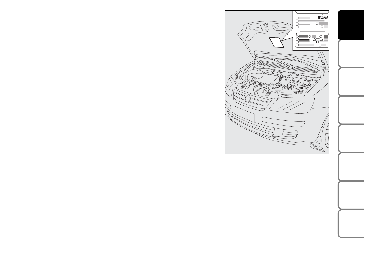
SYMBOLS
Special coloured labels have been attached near or actually on some of
the components of your Fiat Idea. These labels bear symbols that remind
you of the precautions to be taken as regards that particular component.
The plate summarising the symbols used can be found under the bonnet.
THE FIAT CODE SYSTEM
To further protect you car from theft, it has been fitted with an engine
immobilising system. This system is automatically activated when the
ignition key is removed.
An electronic device, in fact, is fitted in each ignition key grip. The device
transmits a radio-frequency signal when the engine is started through a
special aerial built into the ignition switch. The modulate signal, which
changes each time the engine is started, is the “password”, by means of
which the control unit recognises the key and enables to start the engine.
OPERATION
Each time the car is started turning the ignition key to MAR, the Fiat
CODE system control unit sends a recognition code to the engine
control unit to deactivate the inhibitor.
The code is sent only if the Fiat CODE system control unit has
recognised the code transmitted from the key.
Each time the ignition key is turned to the STOP position, the Fiat CODE
system deactivates the functions of the engine electronic control unit.
5
SAFETY
DEVICES
CORRECT USE
OF THE CAR
WARNING
LIGHTS AND
MESSAGES
IN AN
EMERGENCY
CAR
MAINTENANCE
TECHNICAL
SPECIFICATIONS
INDEX
DASHBOARD
AND CONTROLS
F0H0012m
Page 7
At starting, if the code has not been recognised
correctly, the warning light Ywill come on.
In this case, the key should be moved to the STOP
position and then back to MAR; if the lock continues,
possibly try again with the other key provided with the
car. If it is still not possible to start the car, follow the
instructions given in chapter “In an emergency” and
then contact a Fiat Dealership.
IMPORTANT Every key has its own code, which must
be memorised by the system control unit. To
memorise new keys, up to a maximum of eight, apply
to Fiat Dealership.
Warning light
Y
coming on when driving
❒ If the warning light
Y
turns on, this means that
the system is running a self-test (for example for a
voltage drop). At the first stop, turn the ignition
key to STOP and then to MAR again: if no failure is
detected warning light
Y
will not come on.
❒ If the warning light
Y
stays on, repeat the
procedure described previously leaving the key at
STOP for over 30 seconds. Should the
inconvenience persists, contact a Fiat Dealership.
❒ If the warning light
Y
stays on this means that the
code has not been recognised. In this case, the key
should be moved to the STOP position and then
back to MAR; if the lock continues, possibly try
again with the other key provided with the car. If it
is still not possible to start the car, follow the
instruction given in chapter “In an emergency”) and
then contact a Fiat Dealership.
6
SAFETY
DEVICES
CORRECT USE
OF THE CAR
WARNING
LIGHTS AND
MESSAGES
IN AN
EMERGENCY
CAR
MAINTENANCE
TECHNICAL
SPECIFICATIONS
INDEX
DASHBOARD
AND CONTROLS
The electronic components inside the key may be damaged if the key is submitted to sharp knocks.
Page 8
KEY KIT AND DOOR LOCKING
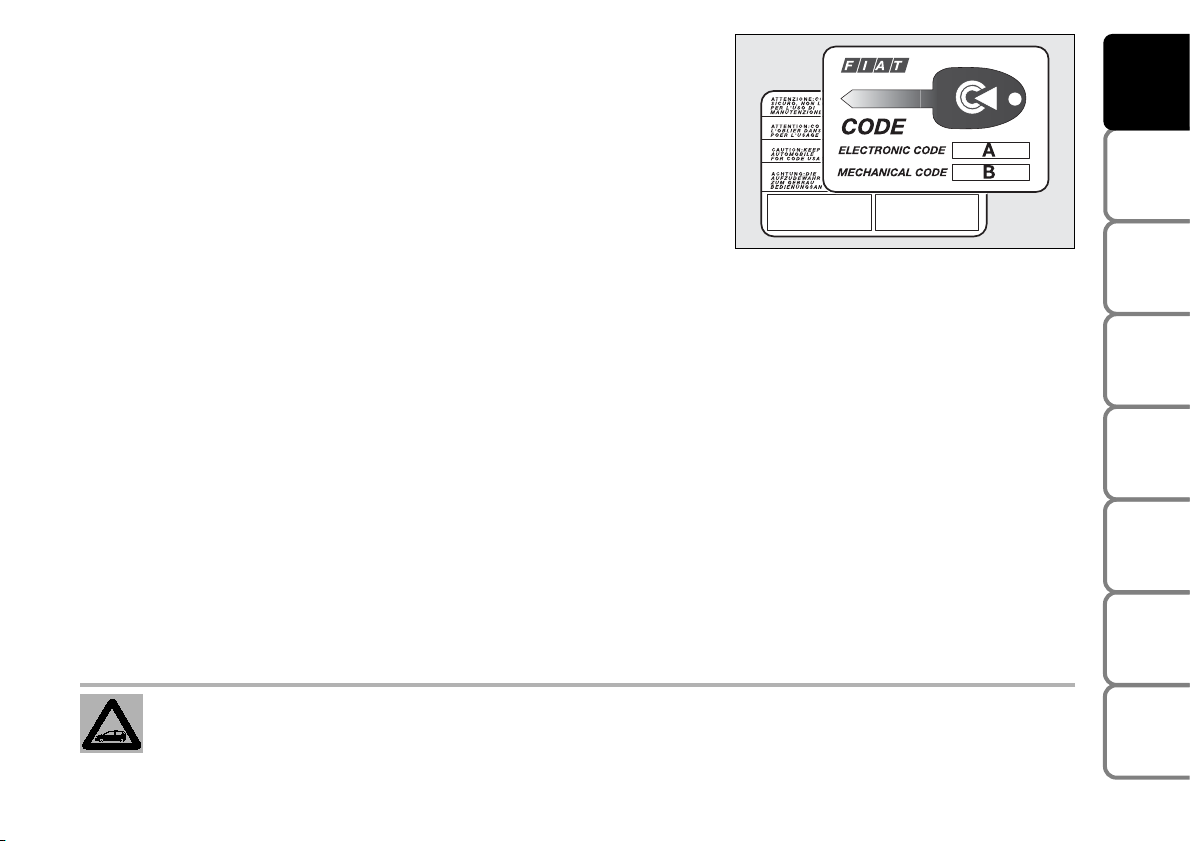
CODE CARD
The car is delivered with the keys and the CODE card which bears the
following:
❒ the electronic code (A) to be used for emergency starting (see
“Emergency starting” in section “Correct use of the car”);
❒ the mechanical key code (B) to be given to the Fiat Dealership when
ordering duplicate keys.
Make sure you have the electronic code (A) with you at all times in the
event you have to perform an emergency start-up.
IMPORTANT In order to ensure perfect efficiency of the electronic
devices contained inside the keys, they should never be exposed to direct
sunlight.
7
SAFETY
DEVICES
CORRECT USE
OF THE CAR
WARNING
LIGHTS AND
MESSAGES
IN AN
EMERGENCY
CAR
MAINTENANCE
TECHNICAL
SPECIFICATIONS
INDEX
DASHBOARD
AND CONTROLS
All the keys and the CODE card must be handed over to the new owner when selling the car.
F0H0013m
Page 9
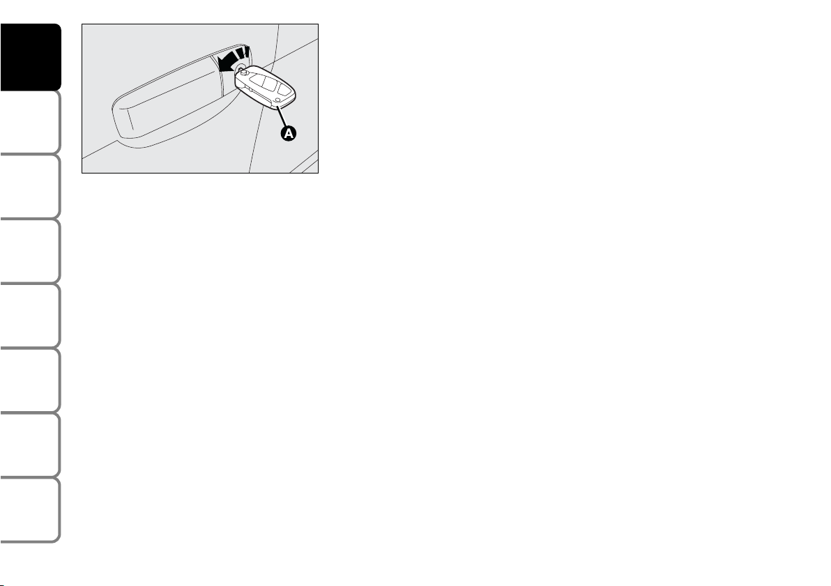
MAIN KEY WITH REMOTE CONTROL
The metal insert (A) of the key is grip-retractable.
The key operates:
❒ the ignition switch;
❒ driver’s door lock;
❒ passenger side airbag deactivation switch;
❒ the dead lock device (where provided).
❒ cut-in of door lock device (D) when the electric system is failing (e.g.
run-down battery);
❒ cut-in of child lock safety device (E) on rear doors.
Button (B) opens the metal insert (A).
To refit the metal insert (A) into the key grip:
– keep button (B) pressed
– move the metal insert (A)
– release button (B) and then turn the metal insert (A) until hearing the
click as it locks into place.
Button
Ë
unlocks the doors, the tailgate and the fuel cap.
Button
Á locks the doors, the tailgate and the fuel cap.
Button
R
unlocks the boot.
Led (C) (where required) comes on when sending the control to the
receiver.
8
SAFETY
DEVICES
CORRECT USE
OF THE CAR
WARNING
LIGHTS AND
MESSAGES
IN AN
EMERGENCY
CAR
MAINTENANCE
TECHNICAL
SPECIFICATIONS
INDEX
DASHBOARD
AND CONTROLS
F0H0015m
WARNING
Button (B) should only be pressed when the key is away from the body, in
particular from the eyes and from objects that can be spoilt (e.g. clothes). Make
sure the key can never be touched by others, especially children, who may
inadvertently press the button.
F0H0246m
Page 10
IMPORTANT The remote control system frequency can be disturbed by
significant radio transmissions outside the car (e.g: mobile phones, HAM
radio systems, etc.) that could cause remote control malfunctioning.
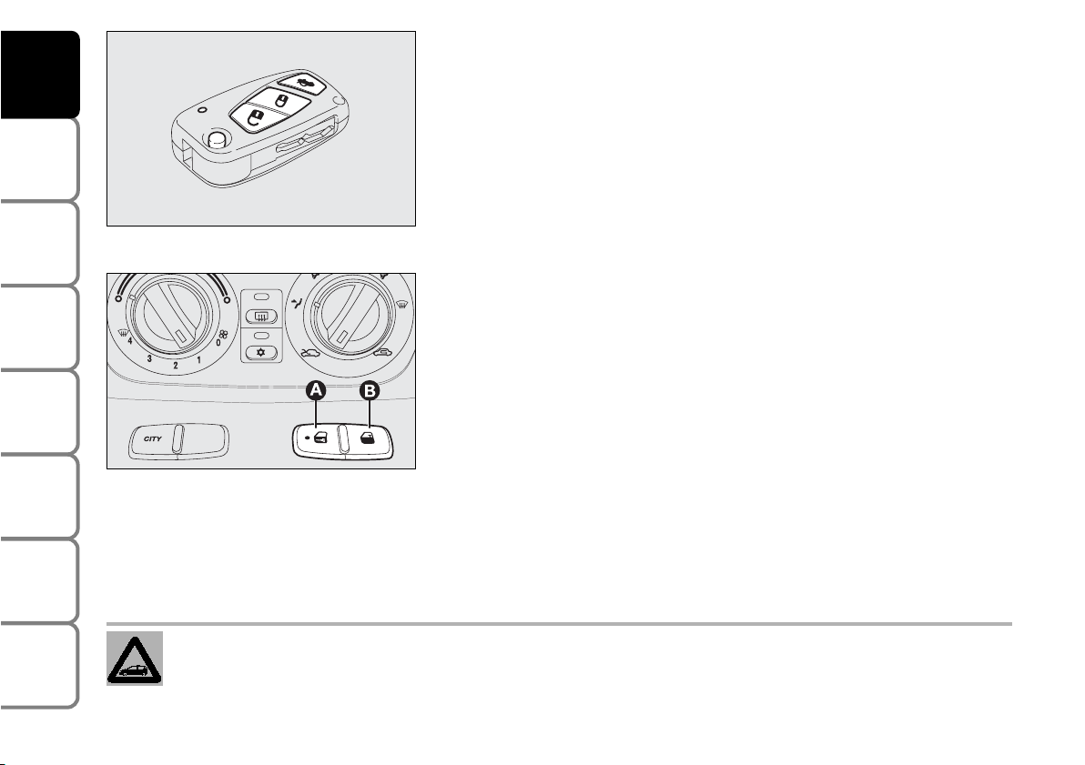
Opening the doors and the tailgate
Pressing and keeping the pushbutton pressed
Ë:
for a short time: remote
unlocking of doors, boot lid, unlocking of fuel lid, timed switching on of
inner roof lamp and double blinking.
Doors will be unlocked automatically if the fuel inertial cut-off switch
comes into operation.
Use the “Set-up menu” of the reconfigurable multifunction display (see
the relevant paragraph in section “Dashboard and controls”) to set the
system so that when pressing button
Ë
only the driver’s door will open.
IMPORTANT The remote control system frequency can be disturbed by
significant radio transmissions outside the car (e.g: mobile phones, HAM
radio systems, etc.) that could cause remote control malfunctioning.
Closing the doors and the tailgate
Pressing and keeping the pushbutton pressed
Á: ffor a short time: remote
locking of doors, boot lid, locking of fuel lid, switching off of inner roof
lamp and single blinking.
Press the button twice quickly to activate the dead lock device (see
paragraph “Dead lock device”) (where provided).
Deterrence led
When locking the doors, the led on button (A) switches on for about 3 seconds and than starts flashing (deterrence
function). Once doors are locked, if one or more doors or the tailgate are not closed correctly, the led and
direction indicators will start flashing quickly.
IMPORTANT The remote control system frequency can be disturbed by significant radio transmissions outside the
car (e.g: mobile phones, HAM radio systems, etc.) that could cause remote control malfunctioning.
9
SAFETY
DEVICES
CORRECT USE
OF THE CAR
WARNING
LIGHTS AND
MESSAGES
IN AN
EMERGENCY
CAR
MAINTENANCE
TECHNICAL
SPECIFICATIONS
INDEX
DASHBOARD
AND CONTROLS
F0H0016m
F0H0100m
Page 11
10
SAFETY
DEVICES
CORRECT USE
OF THE CAR
WARNING
LIGHTS AND
MESSAGES
IN AN
EMERGENCY
CAR
MAINTENANCE
TECHNICAL
SPECIFICATIONS
INDEX
DASHBOARD
AND CONTROLS
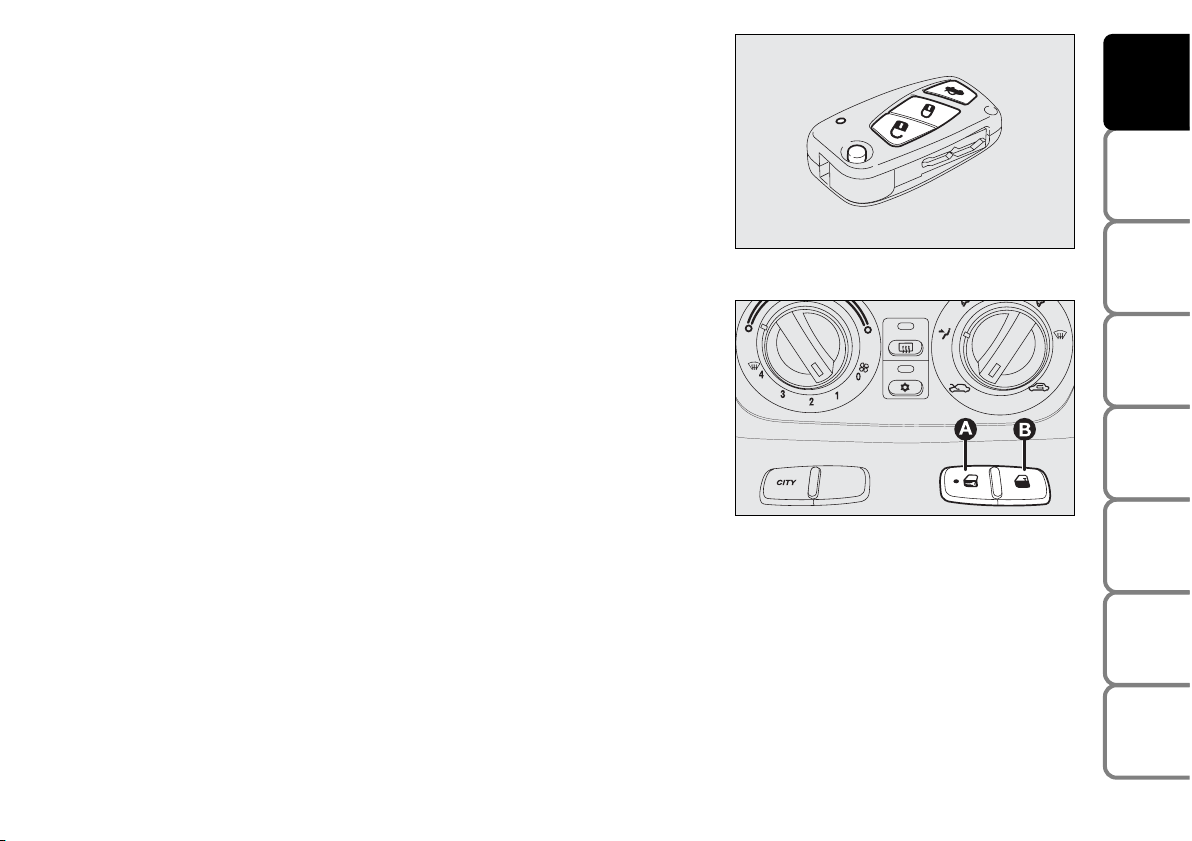
Opening the tailgate from the outside
The tailgate can be opened from the outside by pressing and keeping
pressed the remote control button
R
. Tailgate opening will obtain
double direction indicators flashing; tailgate closing is indicated by one
flashing.
IMPORTANT The remote control system frequency can be disturbed by
significant radio transmissions outside the car (e.g: mobile phones, HAM
radio systems, etc.) that could cause remote control malfunctioning.
F0H0016m
F0H0100m
Locking doors from the inside
With doors closed, press button (A) or (B) set in the middle of the
dashboard to respectively lock or unlock doors.
IMPORTANT Door locking from inside will not cut-in if one door is not
prefectly closed or there is a system failure.
If the cause of the failure is removed, the device will start working
properly.
If the inside locking button is pressed accidentally, when getting out of the car only the doors used
will unlock whereas the tailgate will stay locked.To realign the system, press the lock / unlock
button again.
Page 12
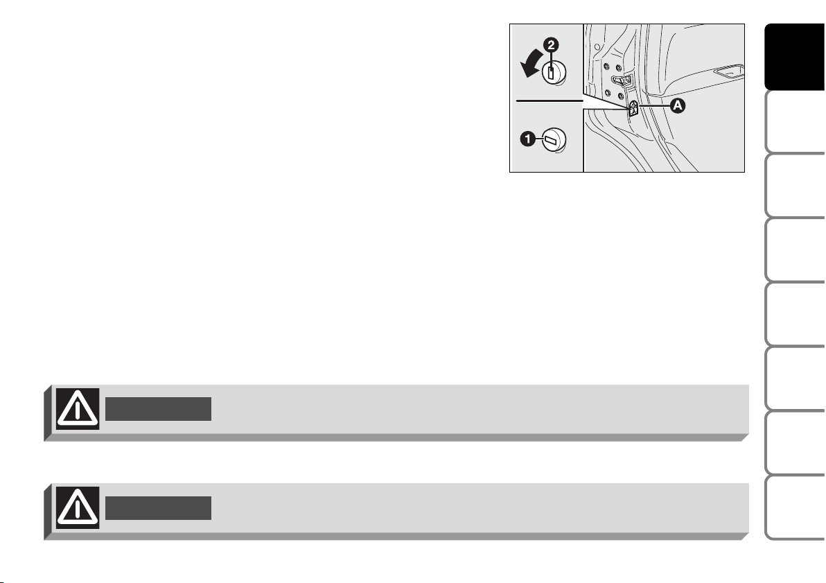
CHILD LOCK
To prevent opening the rear doors from the inside.
This device can be engaged only with doors open.
❒ position 1 - engaged (door locked);
❒ position 2 - disengaged (door openable from inside).
The device (A) is engaged even if the doors are unlocked by the
centralised system.
IMPORTANT Always use the lock when transporting children.
IMPORTANT After engaging the lock, check by trying to open a rear
door with the internal handle.
11
SAFETY
DEVICES
CORRECT USE
OF THE CAR
WARNING
LIGHTS AND
MESSAGES
IN AN
EMERGENCY
CAR
MAINTENANCE
TECHNICAL
SPECIFICATIONS
INDEX
DASHBOARD
AND CONTROLS
F0H0101m
Child lock device (A) is properly engaged only if after turning the revolving plug it
clicks in horizontal position (1).
WARNING
Child lock device (A) is properly disengaged only if after turning the revolving plug
it clicks in vertical position (2).
WARNING
Page 13
12
SAFETY
DEVICES
CORRECT USE
OF THE CAR
WARNING
LIGHTS AND
MESSAGES
IN AN
EMERGENCY
CAR
MAINTENANCE
TECHNICAL
SPECIFICATIONS
INDEX
DASHBOARD
AND CONTROLS
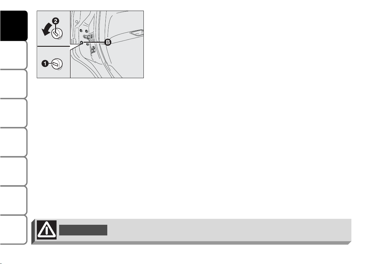
EMERGENCY DEVICE FOR LOCKING DOORS FROM THE
OUTSIDE
Doors are fitted with a special device enabling to lock all doors when the
electric system is failing (no current).
To lock the doors:
❒ fit the ignition key into the revolving plug (B)
❒ turn the device to position 1 and close the door.
To open the doors:
❒ fit the ignition key into the revolving plug of the driver’s door and
turn it counterclockwise
❒ open the driver’s door
❒ once inside the car, open the other doors using the levers set on
door handles.
F0H0247m
Never operate the child lock device and the door handle at the same time.
WARNING
Page 14
13
SAFETY
DEVICES
CORRECT USE
OF THE CAR
WARNING
LIGHTS AND
MESSAGES
IN AN
EMERGENCY
CAR
MAINTENANCE
TECHNICAL
SPECIFICATIONS
INDEX
DASHBOARD
AND CONTROLS
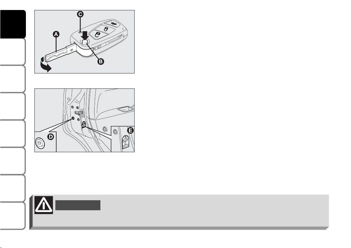
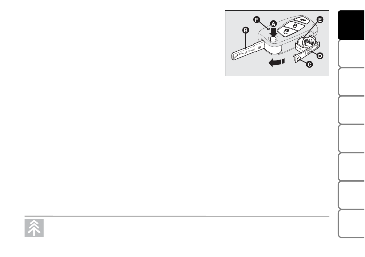
Replacing the battery of the key with remote control
If when pressing the remote control buttons the led (F) on the key
flashes briefly only once, the battery should be replaced with an
equivalent one that can be purchased at common stores.
Battery replacement:
❒ press button (A) and move the metal insert (B) to open position;
❒ use a finely-tipped screwdriver to turn the screw (C);
❒ pull out the battery holder (D) and replace the battery (E) making
sure that the bias is correct;
❒ re-insert the battery holder (D) in the key and lock it turning the
screw (C).
Request for additional remote controls
The system can recognise up to 8 keys with incorporated remote
control. Should a new key with remote control be necessary, contact a
Fiat Dealership, taking with you the CODE card, a personal identity
document and the car’s ownership documents.
F0H0018m
Used batteries are harmful to the environment. They should be disposed of as specified by law in
the special containers provided, or take them to a Fiat Dealership, which will deal with their
disposal.
Page 15

14
SAFETY
DEVICES
CORRECT USE
OF THE CAR
WARNING
LIGHTS AND
MESSAGES
IN AN
EMERGENCY
CAR
MAINTENANCE
TECHNICAL
SPECIFICATIONS
INDEX
DASHBOARD
AND CONTROLS
KEY WITHOUT REMOTE CONTROL (SPARE KEY)
(where required)
The metal insert (A) of the key is grip-retractable.
The key operates:
❒ the ignition switch;
❒ the driver’s door;
❒ passenger side airbag deactivation switch;
❒ the dead lock device (where provided);
❒ cut-in of door lock device (C) when the electric system is failing (e.g.
run-down battery;
❒ cut-in of child lock safety device (D) on rear doors.
Button (B) opens the metal insert (A).
To refit the metal insert (A) into the key grip:
– keep button (B) pressed
– move the metal insert (A)
– release button (B) and then turn the metal insert (A) until hearing the
click as it locks into place.
F0H0014m
WARNING
Button (B) should only be pressed when the key is away from the body, in
particular from the eyes and from objects that can be spoilt (e.g. clothes). Make
sure the key can never be touched by others, especially children, who may
inadvertently press the button.
F0H0322m
Page 16

KEY WITHOUT REMOTE CONTROL (SPARE KEY)
(where required)
The metal insert (A) of the key is fixed.
The key operates:
❒ the ignition switch;
❒ the driver’s door;
❒ passenger side airbag deactivation switch;
❒ the dead lock device (where provided);
❒ cut-in of door lock device (C) when the electric system is failing (e.g.
run-down battery);
❒ cut-in of child lock safety device (D) on rear doors.
15
SAFETY
DEVICES
CORRECT USE
OF THE CAR
WARNING
LIGHTS AND
MESSAGES
IN AN
EMERGENCY
CAR
MAINTENANCE
TECHNICAL
SPECIFICATIONS
INDEX
DASHBOARD
AND CONTROLS
F0H0340m
F0H0322m
Page 17
DEAD LOCK DEVICE (where provided)
This safety device enables to inhibit:
❒ door internal handles;
❒ door locking/unlocking buttons set on the
dashboard;
16
SAFETY
DEVICES
CORRECT USE
OF THE CAR
WARNING
LIGHTS AND
MESSAGES
IN AN
EMERGENCY
CAR
MAINTENANCE
TECHNICAL
SPECIFICATIONS
INDEX
DASHBOARD
AND CONTROLS
Once the dead lock device has been actuated, doors cannot be opened from inside
the car in any way whatsoever. For this reason, make sure there are no persons left
inside the car.
WARNING
thus hindering doors opening from inside the
passenger’s compartment in case of attempt to breakinto (e.g. window breaking).
Page 18
17
SAFETY
DEVICES
CORRECT USE
OF THE CAR
WARNING
LIGHTS AND
MESSAGES
IN AN
EMERGENCY
CAR
MAINTENANCE
TECHNICAL
SPECIFICATIONS
INDEX
DASHBOARD
AND CONTROLS
WARNING
If the battery of the key with remote control is down, the dead lock device can be
activated only using the metal insert of the key in the door revolving plug as
previously described.
The dead lock device guarantees the best protection against unwanted access. Therefore, it should be actuated every
time the car is parked and left unattended.
Page 19
Device activation (where provided)
The device is automatically activated on every door in the following
cases:
❒ turning twice the metal insert of the key (A) in closing direction;
❒ pressing twice button
Á.
Device activation is signalled by three flashings of the direction indicators and
flashing of the deterrence led (see the table on next page).
Should one of the doors be not perfectly closed, the dead lock device is not
activated, thus preventing that a person getting into the car from the open door
remains blocked inside the passenger’s compartment when he/she closes the
door.
Device deactivation (where provided)
The device is deactivated automatically on every door in the following
cases:
❒ when unlocking the doors;
❒ when unlocking only the driver’s door;
❒ when turning the ignition key to MAR.
18
SAFETY
DEVICES
CORRECT USE
OF THE CAR
WARNING
LIGHTS AND
MESSAGES
IN AN
EMERGENCY
CAR
MAINTENANCE
TECHNICAL
SPECIFICATIONS
INDEX
DASHBOARD
AND CONTROLS
F0H0020m
Page 20

The main functions that can be activated with the keys (with or without remote control) are the following:
Type of
key
Spare key
without
remote control
Main key
with remote
control
Direction
indicators
flashing (only
with key with
remote control)
Deterrence led
Pressing the pushbutton Ë enables fuel lid to be opened.
19
SAFETY
DEVICES
CORRECT USE
OF THE CAR
WARNING
LIGHTS AND
MESSAGES
IN AN
EMERGENCY
CAR
MAINTENANCE
TECHNICAL
SPECIFICATIONS
INDEX
DASHBOARD
AND CONTROLS
Door opening
Key turning
counterclockwise
(driver’s side)
Key turning
counterclockwise
(driver’s side)
Pressing briefly
button
Ë
Two flashings
Turning off
Door locking
from the outside
Key turning
clockwise
(driver’s side)
Key turning
clockwise
(driver’s side)
Pressing briefly
button
Á
One flashing
Turned on fixed
for approx. 3 seconds, followed by deterrence
led flashing
Dead lock
(where provided)
Double key rotation
in closing
direction
(clockwise)
Double key rotation
in closing direction
(clockwise)
Double pressing
on button
Á
Three flashings
Double flashing and then deterrence
led flashing
Boot
opening
Prolonged pressing (> 2 seconds) on button
R
Two flashings
Deterrence led
flashing
Page 21
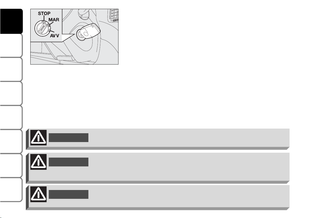
IGNITION SWITCH
The key can be turned to 3 different positions:
❒ STOP: engine off, key can be removed, steering column locked.
Certain electrical devices (e.g.: sound system, power windows…) can
work.
❒ MAR: driving position. All electrical devices are powered.
❒ AVV: engine starting (unstable position).
The ignition switch is fitted with a safety mechanism that, in the event the
engine is not started, turns back the ignition key to STOP before
repeating the starting operation.
STEERING COLUMN LOCK
Engaging
When the key is to STOP remove the key and turn the steering wheel
until it locks.
Disengaging
Rock the steering wheel slightly as you turn the ignition key to MAR.
20
SAFETY
DEVICES
CORRECT USE
OF THE CAR
WARNING
LIGHTS AND
MESSAGES
IN AN
EMERGENCY
CAR
MAINTENANCE
TECHNICAL
SPECIFICATIONS
INDEX
DASHBOARD
AND CONTROLS
Never remove the ignition key while the car is moving. The steering wheel would
automatically lock as soon as you try to turn it. This also applies when the car is
being towed.
WARNING
WARNING
When getting out of the car, always remove the key to prevent any occupants from
accidentally activating the controls. Remember to engage the handbrake. If the car is
parked on uphill slope to engage the first gear. If the car is facing downhill, engage
the reverse gear. Never leave unsupervised children in the car.
F0H0021m
If the ignition device is tampered with (e.g.: attempted theft), have it checked over
by a Fiat Dealership.
WARNING
Page 22
21
SAFETY
DEVICES
CORRECT USE
OF THE CAR
WARNING
LIGHTS AND
MESSAGES
IN AN
EMERGENCY
CAR
MAINTENANCE
TECHNICAL
SPECIFICATIONS
INDEX
DASHBOARD
AND CONTROLS
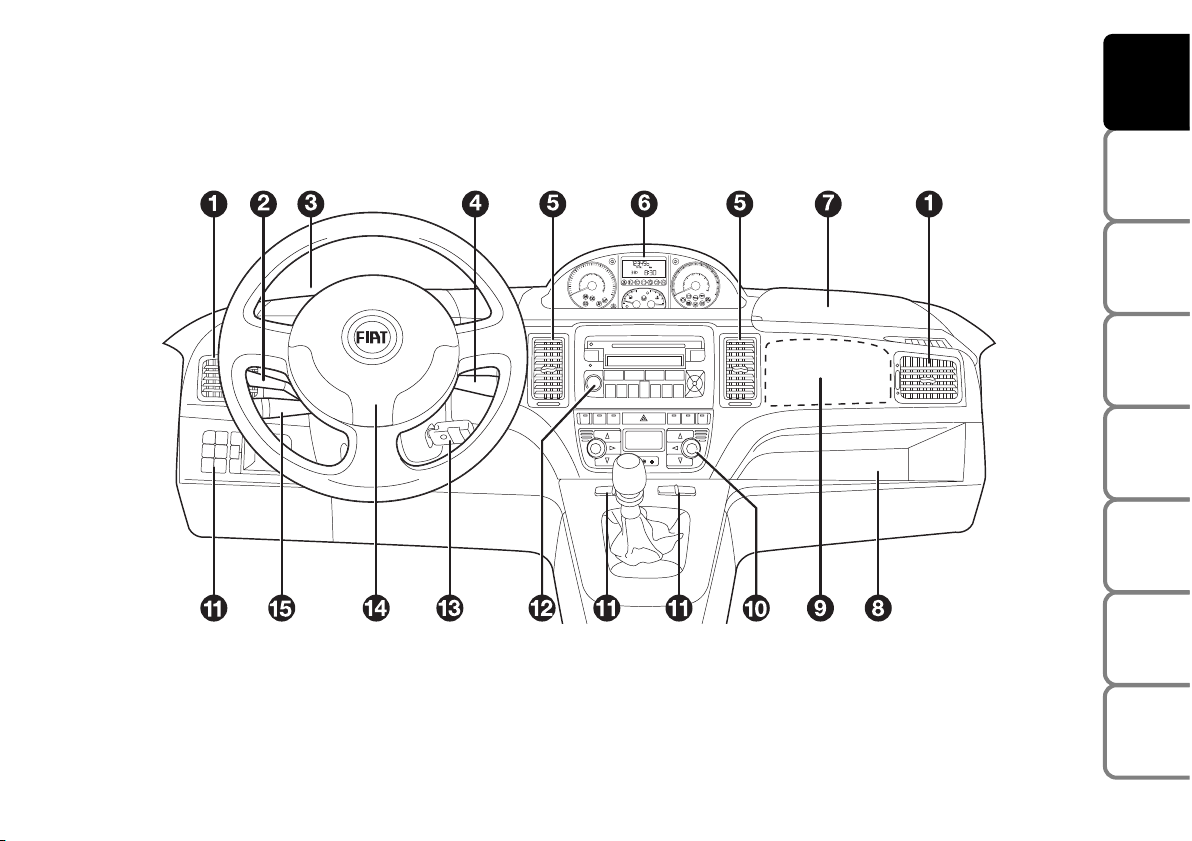
DASHBOARD
The presence and the position of the instruments and warning lights may vary according to the versions.
According to Customer’s requirements the upper and lower central console can offer different solutions, as shown
in the following figures.
F0H0009m
1. Side vents - 2. Left-hand stalk - 3. Upper left oddment compartment - 4. Right-hand stalk - 5. Central vents -
6. Instrument panel - 7. Upper right oddment compartment housing the front passenger’s airbag deactivation switch -
8. Glove compartment - 9. Front passenger’s airbag - 10. Heating/ventilation/climate controls - 11. Control buttons -
12. Sound system (where provided) - 13. Ignition switch - 14. Driver’s airbag - 15. Cruise Control (where provided).
Page 23
22
SAFETY
DEVICES
CORRECT USE
OF THE CAR
WARNING
LIGHTS AND
MESSAGES
IN AN
EMERGENCY
CAR
MAINTENANCE
TECHNICAL
SPECIFICATIONS
INDEX
DASHBOARD
AND CONTROLS
F0H0231m
F0H0232m
F0H0352m
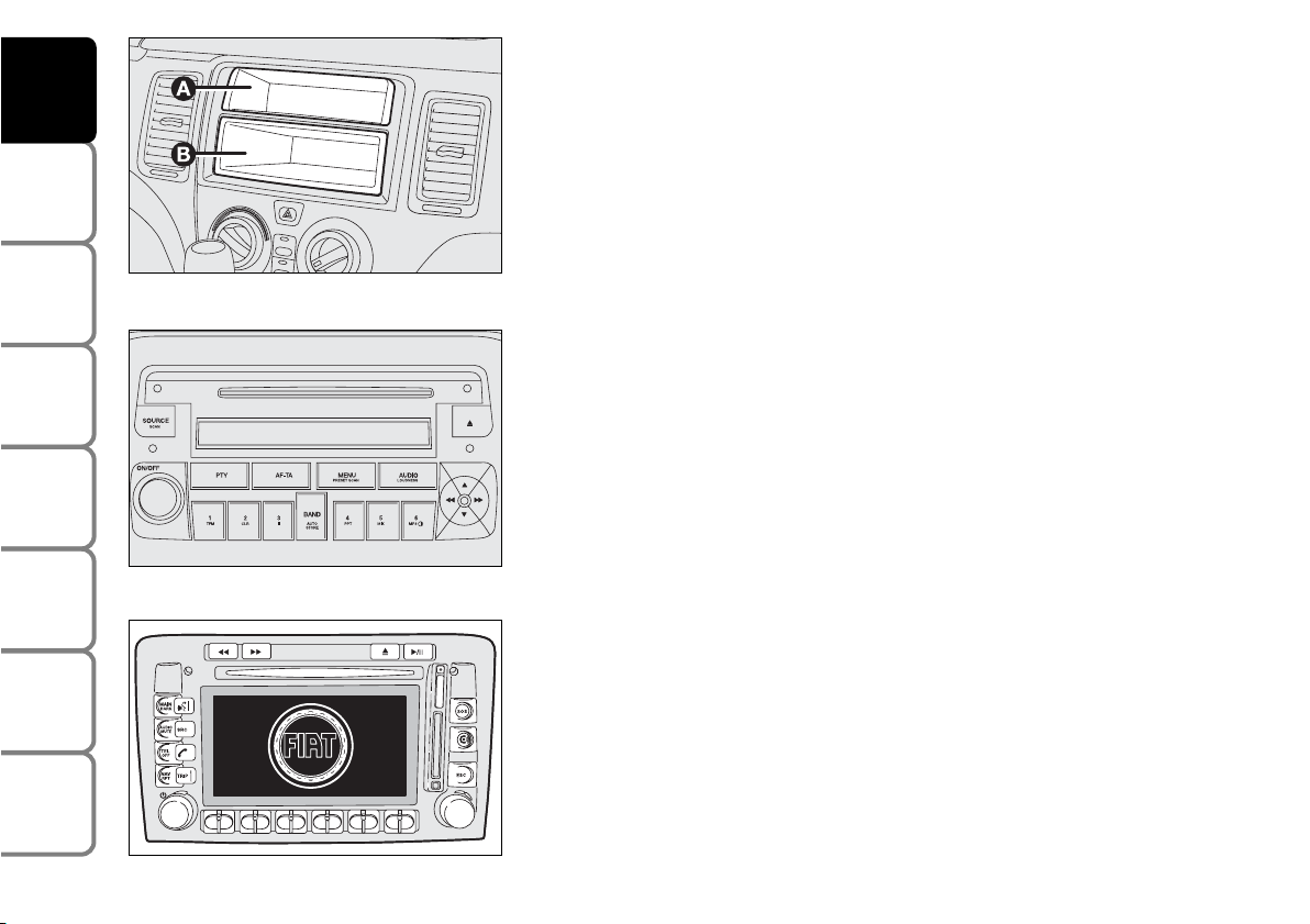
Upper central console:
❒ with fixed oddment compartment (A) and removable oddment
compartment (DIN) (B) for sound system installation;
❒ with sound system upon request.
❒ with Connect Nav +
Page 24

Lower central console:
❒ with heater (A);
23
SAFETY
DEVICES
CORRECT USE
OF THE CAR
WARNING
LIGHTS AND
MESSAGES
IN AN
EMERGENCY
CAR
MAINTENANCE
TECHNICAL
SPECIFICATIONS
INDEX
DASHBOARD
AND CONTROLS
F0H0233m
F0H0234m
F0H0235m
❒ with manual climate control system (B);
❒ with automatic two-zone climate control system (C).
Page 25
24
SAFETY
DEVICES
CORRECT USE
OF THE CAR
WARNING
LIGHTS AND
MESSAGES
IN AN
EMERGENCY
CAR
MAINTENANCE
TECHNICAL
SPECIFICATIONS
INDEX
DASHBOARD
AND CONTROLS
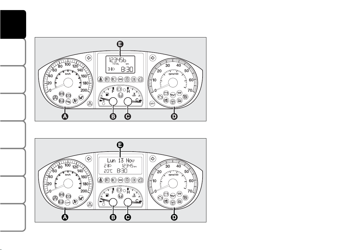
F0H0010m
F0H0011m
Modal
A – Speedometer
B – Fuel gauge with
reserve warning light
C – Engine coolant temperature
gauge with high
temperature warning light
D – Rev counter
E – Multifunction display
cm Warning lights fitted on Multijet ver-
sions only
Comfort
A – Speedometer
B – Fuel gauge with
reserve warning light
C – Engine coolant temperature
gauge with high
temperature warning light
D – Rev counter
E – Reconfigurable multifunction display
cm Warning lights fitted on Multijet
ver-
sions only
INSTRUMENT PANEL
Page 26

INSTRUMENTS
SPEEDOMETER
Speed indicator.
REV. COUNTER
Engine rpm indicator.
IMPORTANT The electronic injection control system gradually shuts off
the flow of fuel when the engine is “over-revving” resulting in a gradual
loss of engine power.
When the engine is idling, the rev counter may indicate a gradual or
sudden highering of the speed.
This is normal as it takes place during normal operation, for example
when activating the climate control system or the fan. In particular a slow
change in the speed preserves the battery charge.
FUEL LEVEL GAUGE
This shows the amount of fuel left in the fuel tank (see the indications
given in paragraph “At the filling station").
The reserve warning light (A) turns on to indicate that approx.
6 litres of fuel are left in the tank.
Do not travel with the fuel tank almost empty: the gaps in fuel delivery
could damage the catalyst.
25
SAFETY
DEVICES
CORRECT USE
OF THE CAR
WARNING
LIGHTS AND
MESSAGES
IN AN
EMERGENCY
CAR
MAINTENANCE
TECHNICAL
SPECIFICATIONS
INDEX
DASHBOARD
AND CONTROLS
F0H0022m
F0H0023m
F0H0241m
Page 27
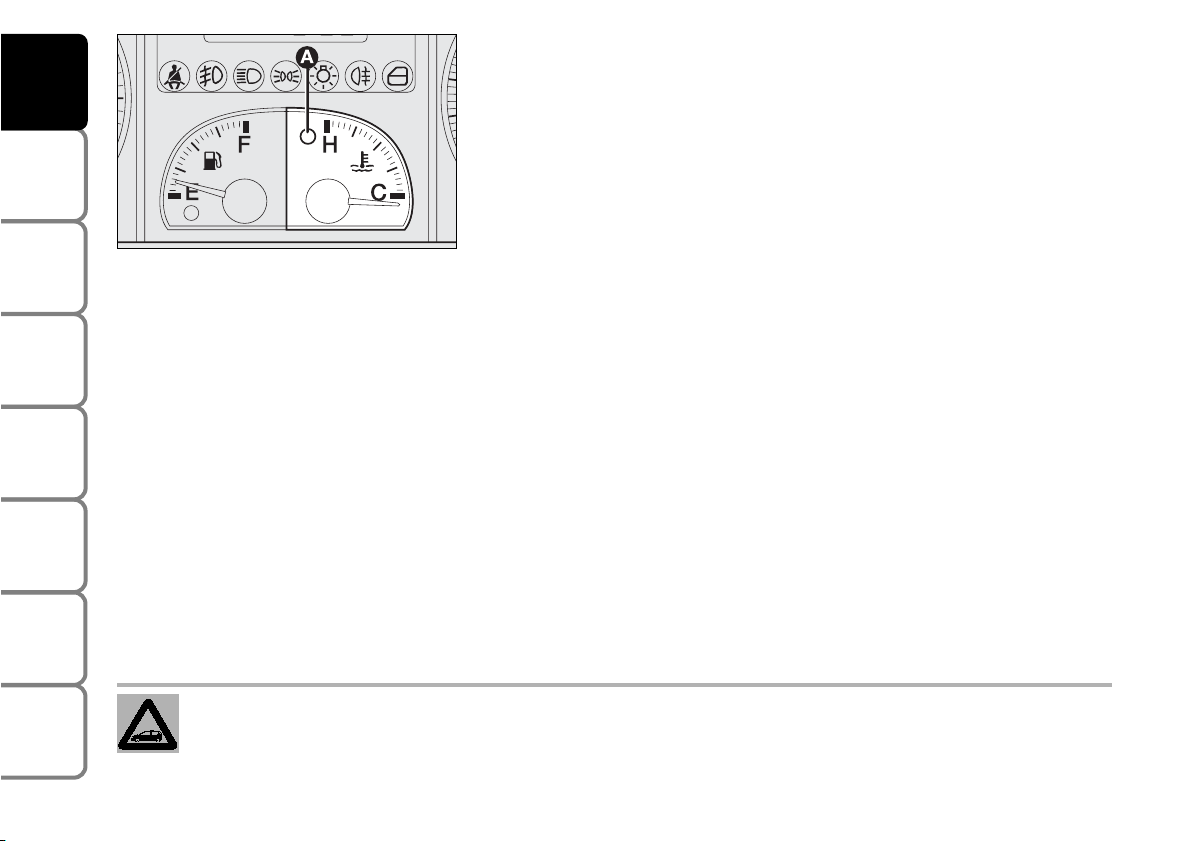
ENGINE COOLANT TEMPERATURE GAUGE
The turning on of the warning light A indicates that the coolant fluid
temperature is too high; in this case, stop the engine and contact a Fiat
Dealership.
This shows the temperature of the engine coolant fluid and begins
working when the fluid temperature exceeds approx. 50°C.
Under normal conditions, the needle should hover around the middle of
the scale according to the working conditions.
IMPORTANT If the needle reaches the low temperature area with
warning light (A) on, this means that there is a failure. Contact a Fiat
Dealership.
26
SAFETY
DEVICES
CORRECT USE
OF THE CAR
WARNING
LIGHTS AND
MESSAGES
IN AN
EMERGENCY
CAR
MAINTENANCE
TECHNICAL
SPECIFICATIONS
INDEX
DASHBOARD
AND CONTROLS
F0H0024m
If the needle reaches the red area, stop the engine immediately and contact a Fiat Dealership.
Page 28

27
SAFETY
DEVICES
CORRECT USE
OF THE CAR
WARNING
LIGHTS AND
MESSAGES
IN AN
EMERGENCY
CAR
MAINTENANCE
TECHNICAL
SPECIFICATIONS
INDEX
DASHBOARD
AND CONTROLS
MULTIFUNCTION DISPLAY
(On two-line mode panel)
The “Multifunction display” shows all the useful information necessary
when driving, more particularly:
INFORMATION ON STANDARD SCREEN
❒ Mileage recorder (A);
❒ Clock (B);
❒ Headlight aiming position display (C) (with dipped beam headlights
on).
With ignition key removed and front doors closed the display is off.
With ignition key removed, when opening one of the front doors the
display comes on showing the clock and the total km covered.
If the “Follow me home” function is on (see paragraph “Follow me
home” in this section), the display will show the time the function is on
instead of the mileage recorder indication (see figure).
INFORMATION ABOUT CAR CONDITIONS
❒ Trip computer information;
❒ Inertial switch operation (at event);
❒ Speed limit exceeded (at event).
F0H0028m
F0H0027m
Page 29
DISPLAY CONTROL BUTTONS
To use the information the “Multifunction display” is able to give, you
should firstly familiarise with the control buttons using them as described
below.
Before doing anything you are advised to read this section thoroughly.
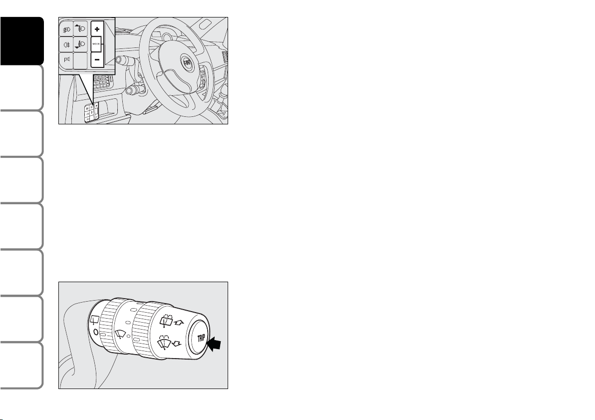
MODE button
To scroll the display and the related options upwards/downwards.
Press for less than 2 seconds (pulse) to confirm the option required
and/or move to the main screen (same option) or access the Menu.
Press for more than 2 seconds to exit the set-up menu and to confirm
selected options.
+ and – buttons
To increase (+) or to decrease (–) the displayed value or to change
displayed values (see next pages).
TRIP button
Press for less than 2 seconds (pulse) to scroll the Trip computer screens.
Press for more than 2 seconds to reset the Trip computer and start a
new mission.
IMPORTANT When in set-up menu, to display the Trip computer info
you have first to quit the set-up menu, then use the Trip button to
display the Trip computer info.
28
SAFETY
DEVICES
CORRECT USE
OF THE CAR
WARNING
LIGHTS AND
MESSAGES
IN AN
EMERGENCY
CAR
MAINTENANCE
TECHNICAL
SPECIFICATIONS
INDEX
DASHBOARD
AND CONTROLS
F0H0025m
FH0026m
Page 30
SET-UP MENU
The “Set-up Menu” enables to perform the following adjustments and/or
settings:
❒ SET CLOCK
❒ BUZZER VOLUME
❒ SPEED LIMIT
❒ SET DISTANCE UNIT.
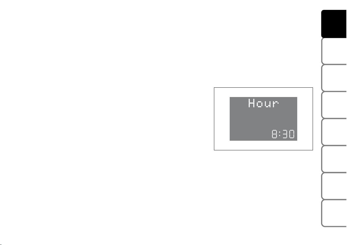
Set clock
The car is delivered with this function set on 24 hours.
Proceed as follows for the required setting:
❒ press repeatedly the MODE button until displaying “Hour”;
❒ press + to increase by one minute;
❒ press – to decrease by one minute.
Keeping buttons + or – pressed for a few seconds obtains automatic fast
increase or decrease, until releasing the buttons.
❒ Press MODE button for over 2 seconds to confirm setting.
29
SAFETY
DEVICES
CORRECT USE
OF THE CAR
WARNING
LIGHTS AND
MESSAGES
IN AN
EMERGENCY
CAR
MAINTENANCE
TECHNICAL
SPECIFICATIONS
INDEX
DASHBOARD
AND CONTROLS
F0H0034m
Page 31

Buzzer volume
Proceed as follows to set the required volume:
❒ press repeatedly the MODE button until displaying “bUZZ”;
❒ press + to increase volume;
❒ press – to decrease volume;
❒ Press MODE button for over 2 seconds to confirm setting.
Speed limit exceeded
With this function it is possible to set the car speed limit which, if
exceeded, automatically sounds a buzzer with the special displaying to
alert the driver.
The car is delivered with this function set to “OFF”.
Proceed as follows for the required setting:
❒ press repeatedly the MODE button until displaying “SPEEd”;
❒ press + to increase the speed value (max. limit: 250 km/h);
❒ press – to decrease the speed value (min. limit: 30 km/h, below this
value the “OFF” mode is resumed);
❒ Press MODE button for over 2 seconds to confirm setting.
30
SAFETY
DEVICES
CORRECT USE
OF THE CAR
WARNING
LIGHTS AND
MESSAGES
IN AN
EMERGENCY
CAR
MAINTENANCE
TECHNICAL
SPECIFICATIONS
INDEX
DASHBOARD
AND CONTROLS
F0H0035m
F0H0036m
Page 32

Set distance unit
Proceed as follows to set the required distance unit (km or miles):
❒ press repeatedly the MODE button until displaying “Unit”
❒ press + or– to change unit;
❒ Press MODE button for over 2 seconds to confirm setting.
31
SAFETY
DEVICES
CORRECT USE
OF THE CAR
WARNING
LIGHTS AND
MESSAGES
IN AN
EMERGENCY
CAR
MAINTENANCE
TECHNICAL
SPECIFICATIONS
INDEX
DASHBOARD
AND CONTROLS
F0H0037m
Page 33

TRIP COMPUTER
Pressing button TRIP, the “Trip computer” function gives information
relating to the operating status of the car.
This function is resettable.
Values displayed are: Cruising range, Travelled distance, Average fuel
consumption, Current fuel consumption, Average speed, Travel time
(driving time). Value selected will be displayed until a new information is
requested.
(*) When the Current fuel consumption value is displayed, the word
TRIP will not be displayed.
Start of journey procedure (reset)
To start a new journey, with the key to MAR, keep the TRIP button
pressed for over 2 seconds (see paragraph “Display control buttons”).
IMPORTANT The “Cruising range” and “Current fuel consumption”
information cannot be reset.
32
SAFETY
DEVICES
CORRECT USE
OF THE CAR
WARNING
LIGHTS AND
MESSAGES
IN AN
EMERGENCY
CAR
MAINTENANCE
TECHNICAL
SPECIFICATIONS
INDEX
DASHBOARD
AND CONTROLS
F0H0029m
F0H0031m
F0H0030m
F0H0032m
F0H0033m
Cruising range
Average/Current
fuel consumption (*)
Distance travelled
Average speed
Trip time
Page 34

Cruising range = shows the distance (in km or
miles) that the car can still cover before needing fuel,
assuming that driving conditions are kept unvaried.
The display will show “- - - -” in the following cases:
❒ value for range to empty lower than 50 km or fuel
level below 4 litres; in this event before “- - - -”
the message “Warning, limited range” will be
displayed (this message will be displayed also if not
in TRIP COMPUTER mode);
❒ in case of car parked with engine running for a
long period, when the car moves off the range to
empty indication will be displayed again.
Travelled distance = shows the km (or miles)
covered from last reset (*).
Average fuel consumption = shows the average
consumption calculated from last reset (*), this value
can be expressed in l/100 km or mpg.
Instant consumption = shows the fuel consumption
variation updated every second, it can be expressed in
l/100 km or mpg. In case of car parked with engine
running the display will show “- - - -”. When the car
moves off the instant consumption indication will be
displayed again.
Average speed = shows the average speed of the
car in relation with total time elapsed from last reset
(*), this value can be expressed in km/h or in mph.
Travel time = time elapsed from last reset (*).
(*) Reset can be:
– “manual”, reset is performed by the driver by
pressing the relevant button (see paragraph
“Control buttons”)
– “automatic”, reset is performed when the travelled
distance reaches 3999.9 km or when travel time
reaches 99:59 (99 hours and 59 minutes)
– after reconnecting the battery.
IMPORTANT Lacking information, Trip computer
values are displayed with “- - - -”. When restoring
normal operating conditions after a failure, calculation
will restart regularly without resetting values.
IMPORTANT After battery disconnection/connection
certain displayed values are equal to “- - - -” until
significant data for calculation are available.
33
SAFETY
DEVICES
CORRECT USE
OF THE CAR
WARNING
LIGHTS AND
MESSAGES
IN AN
EMERGENCY
CAR
MAINTENANCE
TECHNICAL
SPECIFICATIONS
INDEX
DASHBOARD
AND CONTROLS
Page 35

INERTIAL FUEL CUT-OFF SWITCH OPERATION
WARNING MESSAGE
The message shown in the figure is displayed automatically when the fuel
cut-off switch comes into operation after a crash.
This switch stops fuel supply.
See paragraph “Inertial fuel cut-off switch”.
34
SAFETY
DEVICES
CORRECT USE
OF THE CAR
WARNING
LIGHTS AND
MESSAGES
IN AN
EMERGENCY
CAR
MAINTENANCE
TECHNICAL
SPECIFICATIONS
INDEX
DASHBOARD
AND CONTROLS
F0H0038m
If after “FPSon” message displaying you smell fuel or see leaks from the fuel
system, do not reset the switch to avoid fire risk.
WARNING
Page 36

RECONFIGURABLE MULTIFUNCTION
DISPLAY (On three-line comfort panel)
The “Multifunction display” shows all the useful information necessary
when driving, more particularly:
INFORMATION ON STANDARD SCREEN
❒ Date (A).
❒ Mileage recorder (B).
❒ Clock (C).
❒ External temperature (D) (where required).
❒ Headlight aiming position display (with dipped beam headlights on)
(E).
With ignition key removed and front doors closed the display is off.
With ignition key removed, when opening one of the front doors the
display comes on showing the clock and km covered.
If the “Follow me home” function is on (see paragraph “Follow me
home” in this section), the display will show the time the function is on
instead of the mileage recorder indication (see section “Warning lights
and messages”).
35
SAFETY
DEVICES
CORRECT USE
OF THE CAR
WARNING
LIGHTS AND
MESSAGES
IN AN
EMERGENCY
CAR
MAINTENANCE
TECHNICAL
SPECIFICATIONS
INDEX
DASHBOARD
AND CONTROLS
F0H9000m
Page 37

DISPLAY CONTROL BUTTONS
To use the information the “Reconfigurable multifunction display” is able
to give, you should firstly familiarise with the control buttons using them
as described below.
Before doing anything you are advised to read this section thoroughly.
MODE button
Press for less than 2 seconds (pulse) indicated with
b
in the following
diagrams, to confirm the option required and/or move to the main
screen (same option) or access the Menu.
Press for more than 2 seconds indicated with
c
in the following
diagrams, to exit the set-up menu .
+ and – buttons
To scroll the display and the related options upwards/downwards, to
increase/decrease/set (ON/OFF) the value displayed and to adjust the
instrument dimmer (if pressed with “Set-up menu off”).
TRIP button
Press for less than 2 seconds (pulse) indicated with
%
in the
following diagrams, to scroll the Trip computer screens.
Press for more than 2 seconds indicated with
&
in the following
diagrams, to reset the Trip computer and to start a new trip monitoring.
36
SAFETY
DEVICES
CORRECT USE
OF THE CAR
WARNING
LIGHTS AND
MESSAGES
IN AN
EMERGENCY
CAR
MAINTENANCE
TECHNICAL
SPECIFICATIONS
INDEX
DASHBOARD
AND CONTROLS
F0H0025m
FH0026m
Page 38

37
SAFETY
DEVICES
CORRECT USE
OF THE CAR
WARNING
LIGHTS AND
MESSAGES
IN AN
EMERGENCY
CAR
MAINTENANCE
TECHNICAL
SPECIFICATIONS
INDEX
DASHBOARD
AND CONTROLS
INFORMATION ABOUT CAR CONDITIONS
❒ Scheduled maintenance programme intervals.
❒ Trip computer information.
❒ Inertial switch operation (at event).
❒ Instrument panel and two-zone automatic climate
control system light dimmer (where provided).
❒ Display of failure/warning messages.
❒ “DUALDRIVE” electric power steering CITY
function on.
❒ Messages for functions on.
Page 39

SET-UP MENU
The “Set-up Menu” enables to perform the following
adjustments and/or settings using the control buttons
(see previous pages):
❒ SPEED LIMIT
❒ AUTOMATIC HEADLIGHT DAYLIGHT SENSOR
(where provided)
❒ TRIP B ON/OFF
❒ SET CLOCK
❒ CLOCK MODE
❒ SET DATE
❒ SPEEDLOCK
❒ INDEPENDENT BOOT
❒ DRIVER’S DOOR UNLOCKING
❒ DISTANCE UNIT
❒ CONSUMPTION UNIT
❒ TEMPERATURE UNIT (where required)
❒ LANGUAGE
❒ BUZZER VOLUME
❒ BUTTON VOLUME
❒ S.B.R. (Seat Belt Reminder) BUZZER
REACTIVATION (*)
❒ SERVICE
❒ EXIT MENU
38
SAFETY
DEVICES
CORRECT USE
OF THE CAR
WARNING
LIGHTS AND
MESSAGES
IN AN
EMERGENCY
CAR
MAINTENANCE
TECHNICAL
SPECIFICATIONS
INDEX
DASHBOARD
AND CONTROLS
(*) This function can be displayed only after Fiat Dealership has deactivated the S.B.R. system.
Page 40

39
SAFETY
DEVICES
CORRECT USE
OF THE CAR
WARNING
LIGHTS AND
MESSAGES
IN AN
EMERGENCY
CAR
MAINTENANCE
TECHNICAL
SPECIFICATIONS
INDEX
DASHBOARD
AND CONTROLS
INITIAL CHECK
Turning the ignition key to MAR, the multifunction display shows the message “Checking”: the diagnostic phase of all
the electronic systems on the car has started. This lasts few seconds: if no faults are detected, when the engine has
started, the display shows the “Check OK” message.
See section “Warning lights and messages” if faults are found.
Is the engine
started?
YES
If no failures are
present
The “Service schedule” includes vehicle maintenance every 20,000 km (or 12,000 mi) or every year; this is shown automatically, with the
ignition key at MAR, starting from 2,000 km (or 1,240 mi) or 30 days from this deadline and it is shown again every 200 km (or 124 mi) or
3 days. For 1.3 Multijet versions, see “Care and Maintenance” in section “Service schedule to change engine oil and filter and air cleaner.
When a programmed maintenance interval (coupon) is near to come, turning the ignition key to MAR, will display the message “Service”
followed by the number of km, or days to go before car servicing. “Scheduled servicing” message is displayed in km, miles or days according
to the approaching service interval. Contact a Fiat Dealership to carry out any service operation provided by the “Service schedule” or
“Annual inspection plan”, and to reset the display.
If the display shows a failure message,
see details in section “Warning lights
and messages”.
Standard
screen display
or
NO
Page 41

40
SAFETY
DEVICES
CORRECT USE
OF THE CAR
WARNING
LIGHTS AND
MESSAGES
IN AN
EMERGENCY
CAR
MAINTENANCE
TECHNICAL
SPECIFICATIONS
INDEX
DASHBOARD
AND CONTROLS
ACCESS TO MENU SCREEN
After the “Initial check”, it is possible to access the menu screen pressing the button
Q
.
To surf the menu press buttons + or –.
IMPORTANT If after entering the menu no setting/adjustment is performed within 60 seconds, the system exits the
menu automatically and returns to previously displayed screen.
In this case the last selected but not confirmed setting (through button
Q
) is not stored and therefore the
operation shall be repeated.
When the car is running, it is possible to access only the reduced menu (for setting “Speed limit” and “Daylight
sensor automatic headlights”).
When the car is stationary access to the whole menu is enabled.
The following diagram shows the cases described.
Q
= Press “MODE” button for less than two seconds
R
= Press “MODE” button for over two seconds
Page 42

41
SAFETY
DEVICES
CORRECT USE
OF THE CAR
WARNING
LIGHTS AND
MESSAGES
IN AN
EMERGENCY
CAR
MAINTENANCE
TECHNICAL
SPECIFICATIONS
INDEX
DASHBOARD
AND CONTROLS
MENU DESCRIPTION
The menu comprises a series of functions arranged in a “circular fashion”, which can be selected through buttons +
and –, for access to the different select operations and settings (see examples “Lang.” and “Date Adjustm.” below);
for further details, also refer to “Access to menu screen” on next page.
Q
Q
Deutsch
Português
English
Español
Français
Italiano
Nederland
Day
Year Month
Example:
Example:
(where required)
Page 43

42
SAFETY
DEVICES
CORRECT USE
OF THE CAR
WARNING
LIGHTS AND
MESSAGES
IN AN
EMERGENCY
CAR
MAINTENANCE
TECHNICAL
SPECIFICATIONS
INDEX
DASHBOARD
AND CONTROLS
Is the car
moving?
See
“Initial check”
Extended menu screen
only with the car
at a standstill
Example of standard
screen
Menu screen
Q
NO
YES
Speed Lim.
Day Sens.
Exit Menu
Speed Lim.
Light Sensor
Trip B
Clock Adjust.
Clock Mode
Date Adjustm.
Door Lock
Indep. Boot On
Unlock Fda. On
Dist. Unit
Cons.
Temp. Unit
Lang.
Buzzer Vol.
Keys volume
Serv.
Exit Menu
Q
= Press “MODE” button for less than two seconds
R
= Press “MODE” button for over two seconds
Page 44

43
SAFETY
DEVICES
CORRECT USE
OF THE CAR
WARNING
LIGHTS AND
MESSAGES
IN AN
EMERGENCY
CAR
MAINTENANCE
TECHNICAL
SPECIFICATIONS
INDEX
DASHBOARD
AND CONTROLS
SPEED LIMIT EXCEEDED (Speed Lim.)
With this function it is possible to set the car speed limit which, if exceeded, automatically sounds a buzzer and
makes the warning light
è
with the special message on the display (see “Warning lights and messages” section) come
on to alert the driver. To set the speed limit, proceed as follows:
The car is delivered with this function set to “OFF”.
R
Q
Q
Q
R
Q
Q
R
–
+
–
+
Q
See “Initial check”
and “Access to
menu screen”
Use buttons +/- to select
ON/OFF. Set selection flashes.
Return to menu
screen
Menu screen
Return to previously
displayed
screen, e.g.:
Return to menu
screen
Use buttons +/- to set the speed required (during the setting operation the value flashes on the screen). The possible setting is between 30 and 250 km/h or between 20 and 155 mph dependingon the unit set previously (see “Dist. Unit” paragraph described
later). Every press (pulse) of the button +/– increases or decreases
by five units. Keeping button +/- pressed obtains the automatic
fast increase or decrease.
Q
= Press “MODE” button for less than two seconds
R
= Press “MODE” button for over two seconds
R
Page 45

44
SAFETY
DEVICES
CORRECT USE
OF THE CAR
WARNING
LIGHTS AND
MESSAGES
IN AN
EMERGENCY
CAR
MAINTENANCE
TECHNICAL
SPECIFICATIONS
INDEX
DASHBOARD
AND CONTROLS
DAYLIGHT SENSOR AUTOMATIC HEADLIGHTS (Light Sensor) (where provided)
With this function it is possible to adjust the light sensor sensitivity according to 3 levels (level 1 = min. level, level 2
= average level, level 3 = max. level); the higher the sensitivity is, the lower is the external light intensity required to
switch on the lights. This operation can be performed also with the car moving. The car is delivered with this setting
on level “2”. To set the light level required, proceed as follows:
R
Q
Q
–
+
R
–
+
See “Initial check”
and “Access to
menu screen”
Menu screen
Return to menu
screen
Use the + or – buttons to set the light
sensor sensitivity. Set selection flashes.
Return to previously
displayed
screen, e.g.:
Q
= Press “MODE” button for less than two seconds
R
= Press “MODE” button for over two seconds
Q
R
Page 46
45
SAFETY
DEVICES
CORRECT USE
OF THE CAR
WARNING
LIGHTS AND
MESSAGES
IN AN
EMERGENCY
CAR
MAINTENANCE
TECHNICAL
SPECIFICATIONS
INDEX
DASHBOARD
AND CONTROLS
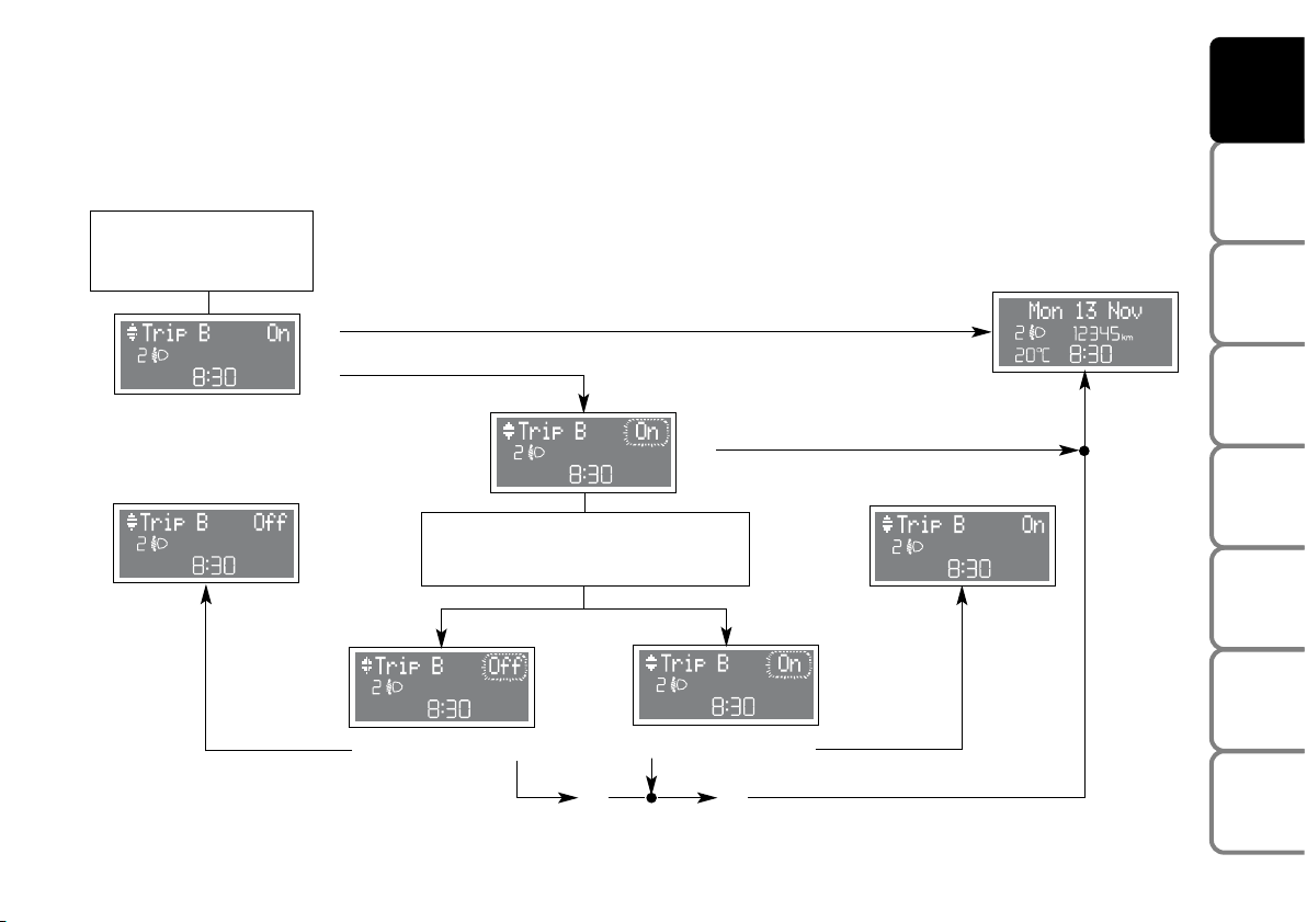
TRIP B ON/OFF (Trip B)
Through this option it is possible to activate (ON) or deactivate (OFF) the Trip B (partial trip) which show “partial
mission” information corresponding to: Trip Dist. B, Aver. Consump. B, Avg. Speed B, Travel time B. For further
information see “General trip - Trip B”.
The car is delivered with this function set to “ON”.
Proced as follows:
R
Q
–
+
–
+
R
Q
Q
Q
Q
See “Initial check”
and “Access to
menu screen”
Menu screen
Use buttons +/– to select
ON/OFF. Set selection flashes.
Return to menu screenReturn to menu screen
Return to previously
displayed
screen, e.g.:
Q
= Press “MODE” button for less than two seconds
R
= Press “MODE” button for over two seconds
R R
Page 47
46
SAFETY
DEVICES
CORRECT USE
OF THE CAR
WARNING
LIGHTS AND
MESSAGES
IN AN
EMERGENCY
CAR
MAINTENANCE
TECHNICAL
SPECIFICATIONS
INDEX
DASHBOARD
AND CONTROLS
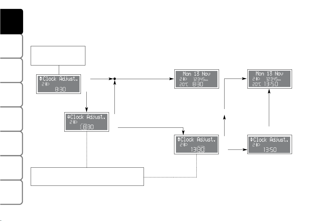
SET CLOCK (Clock Adjust.)
The clock can be set at car delivery.
To set the clock (hours - minutes) proceed as follows:
RR
QQ
–
+
–
+
R
Q
–
+
R
Q
Q
See “Initial check”
and “Access to
menu screen”
Menu screen
Every press (pulse) on the +/– button increases or decreases by one unit. Keeping the +/– button pressed obtains the automatic fast increase or decrease.
Return to menu
screen
Return to previously
displayed
screen, e.g.:
Return to previously
displayed
screen, e.g.:
Q
= Press “MODE” button for less than two seconds
R
= Press “MODE” button for over two seconds
R
Page 48

47
SAFETY
DEVICES
CORRECT USE
OF THE CAR
WARNING
LIGHTS AND
MESSAGES
IN AN
EMERGENCY
CAR
MAINTENANCE
TECHNICAL
SPECIFICATIONS
INDEX
DASHBOARD
AND CONTROLS
CLOCK MODE (Clck. Mode)
This function is used to set the clock in the 12 hour or 24 hour mode. To adjust proceed as follows:
The car is delivered with this function set to 24h.
8:30
R
Q
–
+
–
+
R
8:30
Q
Q
See “Initial check”
and “Access to
menu screen”
Menu screen
Use buttons +/– to select
12 h or 24 h mode.
Set selection flashes.
Return to menu screen
Return to menu screen
Return to previously
displayed
screen, e.g.:
Q
= Press “MODE” button for less than two seconds
R
= Press “MODE” button for over two seconds
Q
Q
R R
Page 49

48
SAFETY
DEVICES
CORRECT USE
OF THE CAR
WARNING
LIGHTS AND
MESSAGES
IN AN
EMERGENCY
CAR
MAINTENANCE
TECHNICAL
SPECIFICATIONS
INDEX
DASHBOARD
AND CONTROLS
SET DATE (Date Adjustm.)
To correct the date (year - month - day) proceed as follows:
Date can be set at car delivery.
See “Initial check”
and “Access to
menu screen”
Menu screen
Every press (pulse) on the +/– button increases or
decreases by one unit. Keeping +/– button pressed
obtains the automatic fast increase or decrease.
Return to menu screen
Return to previously
displayed
screen, e.g.:
Return to previously
displayed
screen, e.g.:
R
Q
–
+
R
Q
Q
–
+
–
+
Q
–
+
R
Q
Q
= Press “MODE” button for less than two seconds
R
= Press “MODE” button for over two seconds
Q
R
R
Page 50

49
SAFETY
DEVICES
CORRECT USE
OF THE CAR
WARNING
LIGHTS AND
MESSAGES
IN AN
EMERGENCY
CAR
MAINTENANCE
TECHNICAL
SPECIFICATIONS
INDEX
DASHBOARD
AND CONTROLS
AUTOMATIC DOOR LOCKING WITH CAR MOVING (Door Lock)
This function:
❒ when activated (ON) locks automatically the doors when the car speed exceeds 20 km/h;
❒ when deactivated (OFF) doesn’t perform automatic door lock.
The car is delivered with this function set to “OFF”.
Return to menu screen
Menu screen
Return to previously
displayed
screen, e.g.:
R
Q
–
+
–
+
R
Q
Q
See “Initial check”
and “Access to
menu screen”
Return to menu screen
Use buttons +/– to select ON/OFF.
Set selection flashes.
Q
= Press “MODE” button for less than two seconds
R
= Press “MODE” button for over two seconds
Q
Q
R R
Page 51

50
SAFETY
DEVICES
CORRECT USE
OF THE CAR
WARNING
LIGHTS AND
MESSAGES
IN AN
EMERGENCY
CAR
MAINTENANCE
TECHNICAL
SPECIFICATIONS
INDEX
DASHBOARD
AND CONTROLS
INDEPENDENT BOOT UNLOCKING (Indep. Boot)
If (ON), when unlocking the door, the boot stays closed and therefore protected: to unlock the boot press button
R on the key with remote control.
If (OFF), the boot is unlocked together with the doors.
The car is delivered with this function set to “OFF”.
R
Q
See “Initial check”
and “Access to
menu screen”
Menu screen
–
+
–
+
Use buttons + or – to select
ON/OFF.
Set selection flashes.
R
Return to menu
screen
Return to menu
screen
Return to previously
displayed
screen, e.g.:
Q
Q
Q
= Press “MODE” button for less than two seconds
R
= Press “MODE” button for over two seconds
Q
Q
R R
Page 52

51
SAFETY
DEVICES
CORRECT USE
OF THE CAR
WARNING
LIGHTS AND
MESSAGES
IN AN
EMERGENCY
CAR
MAINTENANCE
TECHNICAL
SPECIFICATIONS
INDEX
DASHBOARD
AND CONTROLS
DRIVER’S DOOR UNLOCKING (Unlock. Fda.)
This function:
❒ when activated (ON) enables to open just the driver’s door through remote control pulse
❒ when deactivated (OFF) enables simultaneous door opening through remote control pulse.
The car is delivered with this function set to “OFF”.
R
Q
See “Initial check”
and “Access to
menu screen”
Menu screen
–
+
–
+
Use buttons + or – to select
ON/OFF.
Set selection flashes.
R
Return to menu
screen
Return to menu
screen
Q
Q
Return to previously
displayed
screen, e.g.:
Q
= Press “MODE” button for less than two seconds
R
= Press “MODE” button for over two seconds
Q
Q
R R
Page 53

52
SAFETY
DEVICES
CORRECT USE
OF THE CAR
WARNING
LIGHTS AND
MESSAGES
IN AN
EMERGENCY
CAR
MAINTENANCE
TECHNICAL
SPECIFICATIONS
INDEX
DASHBOARD
AND CONTROLS
“DISTANCE” MEASURING UNIT (Dist. Unit)
The car is delivered set to “km”.
The display gives information according to the set unit (km or mi). To select
the required distance unit, proceed as follows:
R
Q
See “Initial check”
and “Access to
menu screen”
Menu screen
–
+
–
+
Use buttons +/– to set the required
distance units (km or mi).
Set selection flashes.
R
Return to menu screen
Return to menu screen
Q
Q
Return to previously
displayed
screen, e.g.:
Q
= Press “MODE” button for less than two seconds
R
= Press “MODE” button for over two seconds
Q
Q
R R
Page 54

53
SAFETY
DEVICES
CORRECT USE
OF THE CAR
WARNING
LIGHTS AND
MESSAGES
IN AN
EMERGENCY
CAR
MAINTENANCE
TECHNICAL
SPECIFICATIONS
INDEX
DASHBOARD
AND CONTROLS
“CONSUMPTION UNIT” (Cons.)
This function enables to select the unit of measure for fuel consumption (km/l, l/100 km or mpg) according to the
previously set distance unit (km or mi, see previous paragraph “Distance measuring unit”). To set this function
proceed as follows:
R
Q
R
Q
R
If setting mi
If setting km
Use buttons +/– to set the
fuel consumption unit km/l or l/100km.
Set selection flashes
Return to
menu screen
Return to menu
screen
See “Initial check”
and “Access to
menu screen”
Menu screen
–
+
Q
Q
Return to
previously displayed
screen, e.g.:
–
+
Q
= Press “MODE” button for less than two seconds - R= Press “MODE” button for over two seconds
Q
Q
R R
Page 55

54
SAFETY
DEVICES
CORRECT USE
OF THE CAR
WARNING
LIGHTS AND
MESSAGES
IN AN
EMERGENCY
CAR
MAINTENANCE
TECHNICAL
SPECIFICATIONS
INDEX
DASHBOARD
AND CONTROLS
“TEMPERATURE” UNIT (Temp. Unit) (where required)
Where required, the car is delivered set to “°C”.
To select temperature unit (°C or °F), proceed as follows:
R
Q
See “Initial check”
and “Access to
menu screen”
Menu screen
–
+
Use buttons +/– to select
the required temperature unit (°C or °F).
Set selection flashes.
R
Return to menu screen
Return to menu screen
Q
Q
Return to previously
displayed
screen, e.g.:
Q
= Press “MODE” button for less than two seconds
R
= Press “MODE” button for over two seconds
Q
Q
R R
Page 56

55
SAFETY
DEVICES
CORRECT USE
OF THE CAR
WARNING
LIGHTS AND
MESSAGES
IN AN
EMERGENCY
CAR
MAINTENANCE
TECHNICAL
SPECIFICATIONS
INDEX
DASHBOARD
AND CONTROLS
LANGUAGE (Lang.)
Display messages can be shown in different languages (Italian, German, English, Spanish, French, Portuguese, Dutch).
To select the required language proceed as follows:
R
See “Initial check”
and “Access to
menu screen”
Menu screen
–
+
–
+
–
+
–
+
–
+
–
+
–
+
Q
Q
Return to menu
screen
Return to previously
displayed
screen, e.g.:
Q
Q
= Press “MODE” button for less than two seconds
R
= Press “MODE” button for over two seconds
R
Page 57

56
SAFETY
DEVICES
CORRECT USE
OF THE CAR
WARNING
LIGHTS AND
MESSAGES
IN AN
EMERGENCY
CAR
MAINTENANCE
TECHNICAL
SPECIFICATIONS
INDEX
DASHBOARD
AND CONTROLS
FAILURE/WARNING BUZZER VOLUME ADJUSTMENT (Buzzer Vol.)
The car is delivered with the volume set to level “4”.
With this function the volume of the buzzer accompanying any failure/warning indication can be adjusted according
to 8 levels. The buzzer can be adjusted and excluded. To exclude the buzzer, use volume buttons +/– to set volume
to “0”.
To adjust the volume proceed as follows:
See “Initial check”
and “Access to
menu screen”
Menu screen
Use buttons +/– to adjust
the buzzer volume.
Set selection flashes.
Return to menu screen
Return to menu screen
Return to previously
displayed
screen, e.g.:
R
Q
8:30
R
–
+
–
+
Q
Q
Q
= Press “MODE” button for less than two seconds
R
= Press “MODE” button for over two seconds
Q
Q
R R
Page 58

57
SAFETY
DEVICES
CORRECT USE
OF THE CAR
WARNING
LIGHTS AND
MESSAGES
IN AN
EMERGENCY
CAR
MAINTENANCE
TECHNICAL
SPECIFICATIONS
INDEX
DASHBOARD
AND CONTROLS
BUTTON VOLUME ADJUSTMENT (Keys Volume)
The car is delivered with the volume set to level “4”. With this function the volume of the roger-beep accompanying
the activation of certain buttons can be adjusted according to 8 levels. The roger-beep can be adjusted and excluded.
To exclude the roger-beep, use volume buttons +/– to set volume to “0”. To adjust the volume proceed as follows:
Menu screen
See “Initial check”
and “Access to
menu screen”
Use buttons +/– to adjust
the roger-beep volume.
Set selection flashes.
Return to menu screen
Return to previously
displayed
screen, e.g.:
R
Q
Q
Q
–
+
–
+
R
Return to menu screen
Q
= Press “MODE” button for less than two seconds
R
= Press “MODE” button for over two seconds
Q
Q
R R
Page 59

58
SAFETY
DEVICES
CORRECT USE
OF THE CAR
WARNING
LIGHTS AND
MESSAGES
IN AN
EMERGENCY
CAR
MAINTENANCE
TECHNICAL
SPECIFICATIONS
INDEX
DASHBOARD
AND CONTROLS
SERVICE (Serv.)
Through the “Service” function it is possible to receive information connected with correct vehicle maintenance.
R
Q
See “Initial check”
and “Access to
menu screen”
Menu screen
Use buttons +/– to select
displaying in km, miles
(mi) or days (dd). Set selection flashes.
R
Return to menu screen
Return to menu screen
Return to previously
displayed
screen, e.g.:
continues on next page
–
+
–
+
R
Q
Q
R
Q
= Press “MODE” button for less than two seconds
R
= Press “MODE” button for over two seconds
Page 60

59
SAFETY
DEVICES
CORRECT USE
OF THE CAR
WARNING
LIGHTS AND
MESSAGES
IN AN
EMERGENCY
CAR
MAINTENANCE
TECHNICAL
SPECIFICATIONS
INDEX
DASHBOARD
AND CONTROLS
The “Service schedule” includes vehicle maintenance every 20,000 km (or 12,000 mi) or every year; this is shown automatically, with the
ignition key at MAR, starting from 2,000 km (or 1,240 miles) or 30 days from this deadline and it is shown again every 200 km (or 124 mi)
or 3 days. For 1.3 Multijet versions, see “Care and Maintenance” in section “Service schedule” to change engine oil and filter and air
cleaner. When a programmed maintenance interval (coupon) is near to come, turning the ignition key to MAR, will display the message
“Service” followed by the number of km or days to go before car servicing. “Service” message is displayed in km or mi or days according to
the approaching service interval. Contact Fiat Dealership to carry out any service operation provided by the “Service schedule” or “Annual
inspection plan” and to reset the display.
Return to menu
screen
Return to previously
displayed
screen, e.g.:
continued from
previous page
R
Q
Q
= Press “MODE” button for less than two seconds
R
= Press “MODE” button for over two seconds
Page 61

60
SAFETY
DEVICES
CORRECT USE
OF THE CAR
WARNING
LIGHTS AND
MESSAGES
IN AN
EMERGENCY
CAR
MAINTENANCE
TECHNICAL
SPECIFICATIONS
INDEX
DASHBOARD
AND CONTROLS
EXIT MENU (Exit Menu)
This is the last function that closes the circular setting cycle listed in the initial menu screen.
R
See “Initial check”
and “Access to
menu screen”
Menu screen
Use button + to return to Speed Lim.
screen (first Menu item).
Return to previously
displayed
screen, e.g.:
–
+
Q
= Press “MODE” button for less than two seconds
R
= Press “MODE” button for over two seconds
Page 62

61
SAFETY
DEVICES
CORRECT USE
OF THE CAR
WARNING
LIGHTS AND
MESSAGES
IN AN
EMERGENCY
CAR
MAINTENANCE
TECHNICAL
SPECIFICATIONS
INDEX
DASHBOARD
AND CONTROLS
TRIP COMPUTER
The “Trip computer” displays information relating to the operating status of the car. This function comprises the
“General trip”, concerning the complete mission of the car and “Trip B”, concerning the partial car mission. The car is
delivered with “Trip B” set to “ON”. This function (as shown in the graph below) is contained within the complete
mission. Both functions are resettable. The “General trip” displays the figures relating to Cruising Range, Travelled
Distance, Average fuel consumption, Current fuel consumption, Average speed, Travel time (driving time). “Trip B”
displays information concerning Travel Distance B, Average fuel consumption B, Average speed B, Travel time B
(driving time). The “Trip B” function can be excluded.
Start of journey procedure (reset)
To start a new journey monitored by the “General Trip”, with the key to MAR, press button
{
on right steering
column stalk with mode &(see paragraph “Display control buttons”).
The reset operation in the presence of the screens concerning the “General trip” makes it possible to reset also the
“Trip B”. The reset operation in the presence of the screens concerning only the “Trip B” makes it possible to reset
only the information associated with this function.
IMPORTANT The “Cruising range” information cannot be reset.
Reset TRIP B
End of partial mission
Start of new partial mission
End of partial mission
Start of new partial mission
Reset TRIP B
End of partial mission
Start of new partial mission
Reset GENERAL TRIP
End of complete mission - Start of new mission
Reset GENERAL TRIP
End of complete mission - Start of new mission
End of partial mission
Start of new partial mission
Reset TRIP B
Reset TRIP B
TRIP B
TRIP B
TRIP B
GENERAL TRIP
˙
˙
˙
˙
˙
˙
˙
˙
%
= Press “TRIP” button for less than two seconds - &= Press “TRIP” button for over two seconds
Page 63

62
SAFETY
DEVICES
CORRECT USE
OF THE CAR
WARNING
LIGHTS AND
MESSAGES
IN AN
EMERGENCY
CAR
MAINTENANCE
TECHNICAL
SPECIFICATIONS
INDEX
DASHBOARD
AND CONTROLS
“Trip computer” information are displayed according to the following diagram:
See “Initial check”
and “Access to
menu screen”
Previously
displayed
screen, e.g.:
(*)
% % %
%
%
%
continues on next page
&
= “Reset General trip” and “Trip B” excluding
“Cruising range” (see paragraph “Reset General trip”).
The two screens concerning a trip item
alternate three times, then the second
one stays on fixed on the display.
%
(*)
(*)
(*)(*)
(*)
(*)
%
= Press “TRIP” button for less than two seconds - &= Press “TRIP” button for over two seconds
Page 64

63
SAFETY
DEVICES
CORRECT USE
OF THE CAR
WARNING
LIGHTS AND
MESSAGES
IN AN
EMERGENCY
CAR
MAINTENANCE
TECHNICAL
SPECIFICATIONS
INDEX
DASHBOARD
AND CONTROLS
continued from previous page
Trip B ON?
NO
YES
Return to previously
displayed screen,
e.g.:
8:30
20oC
% % %
%
&
= “Reset Trip B”
(see paragraph “Reset Trip B”).
(*)
(*)
(*) (*)
%
= Press “TRIP” button for less than two seconds - &= Press “TRIP” button for over two seconds
Page 65

64
SAFETY
DEVICES
CORRECT USE
OF THE CAR
WARNING
LIGHTS AND
MESSAGES
IN AN
EMERGENCY
CAR
MAINTENANCE
TECHNICAL
SPECIFICATIONS
INDEX
DASHBOARD
AND CONTROLS
After resetting “Trip” by pressing the button with &mode, the following functions are displayed:
Reset GENERAL TRIP
&
= “Reset General trip” and “Trip B”
(excluding “Cruising range”).
&
= “Reset Trip B”
Reset TRIP B
All values set to zero
Only partial values are set to zero
%
= Press “TRIP” button for less than two seconds - &= Press “TRIP” button for over two seconds
Page 66

65
SAFETY
DEVICES
CORRECT USE
OF THE CAR
WARNING
LIGHTS AND
MESSAGES
IN AN
EMERGENCY
CAR
MAINTENANCE
TECHNICAL
SPECIFICATIONS
INDEX
DASHBOARD
AND CONTROLS
Cruising range = Shows the distance in km (or mi)
that the car can still cover before needing fuel,
assuming that driving conditions are kept unvaried.
The display will show “- - - -” in the following cases:
❒ value for range to empty lower than 50 km or fuel
level below 4 litres; in this event before “- - - -”
the message “Warning, limited range” will be
displayed (this message will be displayed also if not
in TRIP COMPUTER mode);
❒ in case of car parked with engine running for a
long period, when the car moves off the range to
empty indication will be displayed again.
Travelled distance = shows the km (or miles)
covered from last reset (*).
Average fuel consumption = shows the average
consumption calculated from last reset (*), this value
can be expressed in l/100 km, km/l or mpg.
Instant consumption = shows the fuel consumption
variation updated every second, it can be expressed in
l/100 km or mpg. In case of car parked with engine
running the display will show “- - - -”. When the car
moves off the instant consumption indication will be
displayed again.
Average speed = shows the average speed of the
car in relation with total time elapsed from last reset
(*) and it can be expressed in km/h or in mph.
Travel time = time elapsed from last reset (*).
(*) Reset can be:
– “manual”, reset is performed by the driver by
pressing the relevant button (see paragraph
“Control buttons”)
– “automatic”, reset is performed when the travelled
distance reaches 9999.9 km or when Travel time
reaches 99:59 (99 hours and 59 minutes)
– after reconnecting the battery.
IMPORTANT Lacking information, Trip computer
values are displayed with “- - - -”. When normal
operating condition is reset, calculation of different
units will restart regularly. Values displayed before the
failure will not be reset (*).
IMPORTANT After battery disconnection/connection
certain displayed values are equal to “- - - -” until
significant data for calculation are available.
Page 67

66
SAFETY
DEVICES
CORRECT USE
OF THE CAR
WARNING
LIGHTS AND
MESSAGES
IN AN
EMERGENCY
CAR
MAINTENANCE
TECHNICAL
SPECIFICATIONS
INDEX
DASHBOARD
AND CONTROLS
INSTRUMENT PANEL, DISPLAY AND BUTTON LIGHTING ADJUSTMENT
(LIGHT RHEOSTAT)
With this function it is possible to adjust the lighting (dimming/brightening) of the instrument cluster and two-zone
climate control display (where provided).
To adjust proceed as follows:
See “Initial check”
and “Access to
menu screen”
–
+
–
+
Automatic return to standard screen
after few seconds or by
pressing button
Q
Previously
displayed
screen, e.g.:
Use buttons +/– to carry out required
light adjustment.
F0H0040m
Q
= Press “MODE” button for less than two seconds
R
= Press “MODE” button for over two seconds
Page 68

67
SAFETY
DEVICES
CORRECT USE
OF THE CAR
WARNING
LIGHTS AND
MESSAGES
IN AN
EMERGENCY
CAR
MAINTENANCE
TECHNICAL
SPECIFICATIONS
INDEX
DASHBOARD
AND CONTROLS
If after warning message displaying you smell fuel or see leaks from the fuel
system, do not reset the switch to avoid fire risk.
WARNING
INERTIAL FUEL CUT-OFF SWITCH OPERATION
WARNING MESSAGE
The message shown in the figure is displayed automatically when the fuel
cut-off switch comes into operation after a crash.
This switch stops fuel supply.
See paragraph “Inertial fuel cut-off switch”.
Page 69

WARNING
Any adjustment of the steering wheel position must be carried out only with the
car stationary and the engine turned off.
STEERING WHEEL ADJUSTMENT
The steering wheel can be adjusted both in height (A) and axially (B).
Proceed as follows:
❒ release the lever pulling it towards the steering wheel (position 2);
❒ adjust the steering wheel as required;
❒ lock the lever pushing it forwards (position 1).
68
SAFETY
DEVICES
CORRECT USE
OF THE CAR
WARNING
LIGHTS AND
MESSAGES
IN AN
EMERGENCY
CAR
MAINTENANCE
TECHNICAL
SPECIFICATIONS
INDEX
DASHBOARD
AND CONTROLS
F0H0055m
WARNING
It is absolutely forbidden to carry out whatever after-market operation involving
steering system or steering column modifications (e.g.: installation of anti-theft
device) that could badly affect performance and safety, cause the lapse of
warranty and result in car non-compliance with the regulations in force.
Page 70

69
SAFETY
DEVICES
CORRECT USE
OF THE CAR
WARNING
LIGHTS AND
MESSAGES
IN AN
EMERGENCY
CAR
MAINTENANCE
TECHNICAL
SPECIFICATIONS
INDEX
DASHBOARD
AND CONTROLS
F0H0041m
F0H0042m
SEAT ADJUSTMENT
FRONT SEATS
Moving the seat backwards or forwards
Lift the lever (A) and push the seat forwards or backwards: in the driving
position the arms should rest on the rim of the steering wheel.
Always check that the seat is firmly locked in the runners by trying to
move it back and forth.
Seat height adjustment (driver’s side) (where provided)
Move repeatedly lever (B) upwards or downwards to achieve the
required height.
IMPORTANT Adjustment must be carried out only seated in the driver’s
seat with the car at a standstill.
Back rest angle adjustment
Move lever (D) as shown by the arrow, set the back rest in the required
position, then release the lever.
Lumbar adjustment (where provided)
Turn knob (C) clockwise or counterclockwise to increase or decrease
lumbar adjustment.
After adjustments, always check that the seat is firmly locked in the runners.
WARNING
Page 71

70
SAFETY
DEVICES
CORRECT USE
OF THE CAR
WARNING
LIGHTS AND
MESSAGES
IN AN
EMERGENCY
CAR
MAINTENANCE
TECHNICAL
SPECIFICATIONS
INDEX
DASHBOARD
AND CONTROLS
Armrest adjustment (where provided)
To use the armrest, move it from position 1 to position 2.
Setting the passenger’s seat to “table” configuration
Set the armrest (where provided) in vertical position.
From driver’s seat or rear seats, move the lever (A) as shown by the
arrow, tilt the back rest on the cushion, then release the lever. In this
position the back rest can be used like a table.
Setting the driver’s seat to “table” configuration
Remove the head restraint completely (see “Head restraint removal” in
section “Head restraints”) then follow the previously described procedure.
Seat warming (where provided)
To switch on/off seat warming on driver’s side press button (B), press
button (C) for the passenger’s side.
The led on the button will light up when the function is on.
F0H0043m
F0H0044m
F0H0045m F0H0046m
Page 72

71
SAFETY
DEVICES
CORRECT USE
OF THE CAR
WARNING
LIGHTS AND
MESSAGES
IN AN
EMERGENCY
CAR
MAINTENANCE
TECHNICAL
SPECIFICATIONS
INDEX
DASHBOARD
AND CONTROLS
F0H0047m
REAR SLIDING SEAT
Adjustments from inside the car
Moving the seat backwards or forwards
Lift lever (A) or lever (B) respectively to adjust the required seat section,
then push the seat backwards or forwards.
Back rest angle adjustment
Use lever (C) to set the back rest as required then release the lever.
To prevent malfunctioning: always press lever (C) down completely.
REAR FIXED SEAT (where provided)
For tilting the seat, see paragraph “Boot extension”
F0H0252m
F0H0253m
Adjustments from the boot
Moving the seat backwards or forwards
Use handles (F) and (G) to adjust the required seat section, then push the
seat backwards or forwards.
WARNING
After adjustments, always check that the
seat is firmly locked in the runners.
Page 73

72
SAFETY
DEVICES
CORRECT USE
OF THE CAR
WARNING
LIGHTS AND
MESSAGES
IN AN
EMERGENCY
CAR
MAINTENANCE
TECHNICAL
SPECIFICATIONS
INDEX
DASHBOARD
AND CONTROLS
F0H0049m
Back rest angle adjustment
Use lever (A) or lever (B) to adjust the required back rest section, then
release the lever.
Central seat back rest adjustment from inside the car
To set the central seat back rest in horizontal position:
❒ operate lever (D) (one per side)
❒ lower the central seat back rest down completely
❒ release the lever.
With central seat back rest completely lowered on the cushion and
relevant head restraint removed (as shown in the figure), it is possible to
use the glass holder (A) (where provided).
To bring the central back rest back to vertical position: use again lever
(D) (one per side) and set it in line with rear side seat backs, until the
securing clip (E) locks into place
F0H0051m
Once you have released the lever, check
that the seat is firmly locked in the
runners by trying to move it back and
forth. Failure to lock the seat in place
could result in the seat moving suddenly.
WARNING
F0H0050m
Page 74

73
SAFETY
DEVICES
CORRECT USE
OF THE CAR
WARNING
LIGHTS AND
MESSAGES
IN AN
EMERGENCY
CAR
MAINTENANCE
TECHNICAL
SPECIFICATIONS
INDEX
DASHBOARD
AND CONTROLS
For maximum safety, keep the back of your seat upright, lean back into it and
make sure the seat belt fits closely across your hips.
WARNING
F0H0255m
Central seat back rest adjustment from the boot
Pull band (F) and push forward the top of the back rest at the same time
until releasing the locking clip. Bring the back rest to horizontal position
then, release band (F). Reverse this procedure to reset the back rest in
vertical position. Check for clip locking into place.
Page 75
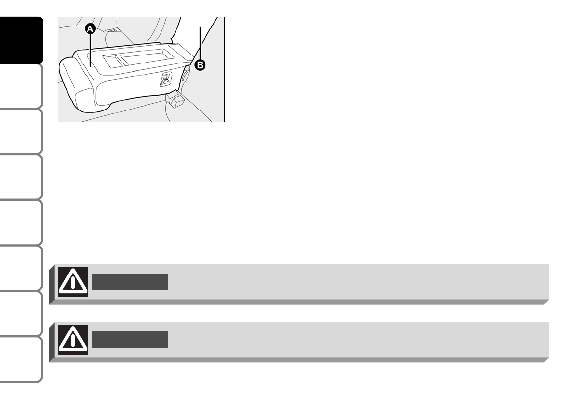
74
SAFETY
DEVICES
CORRECT USE
OF THE CAR
WARNING
LIGHTS AND
MESSAGES
IN AN
EMERGENCY
CAR
MAINTENANCE
TECHNICAL
SPECIFICATIONS
INDEX
DASHBOARD
AND CONTROLS
WARNING
Only make adjustments when the car is stationary.
Ski tunnel
To use the ski tunnel, the armrest shall be lowered down completely.
It can be used to carry long objects (e.g.: skis), fitting them into the
tunnel from the boot.
To access the ski tunnel (B), lower the rear central back rest (A) (as
previously described)
WARNING
Always check that loads are anchored properly to prevent them being thrown
against the passengers in case of accident or sharp braking.
F0H0249m
Page 76
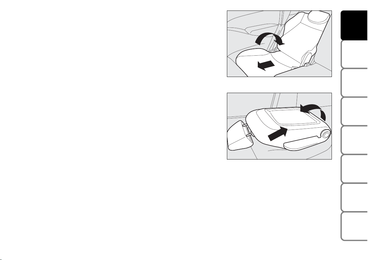
75
SAFETY
DEVICES
CORRECT USE
OF THE CAR
WARNING
LIGHTS AND
MESSAGES
IN AN
EMERGENCY
CAR
MAINTENANCE
TECHNICAL
SPECIFICATIONS
INDEX
DASHBOARD
AND CONTROLS
Relax position, passenger side
To obtain the relax position, open the rear door and:
❒ tilt the passenger seat to “table” position (see “Setting the passenger’s
seat to table configuration” in this section);
❒ push the rear seat completely forward;
❒ push the passenger’s seat (tilted) completely backward;
❒ remove the rear parcel shelf (see “Rear parcel shelf removal” in this
section);
❒ move the rear seat back rest to the required position.
Relax position, driver side
Same procedure but remove completely the driver’s head restraint (see
“Head restraints” in this section).
IMPORTANT See section “Boot Extension” for operations concerning
seat positioning to extend the boot.
F0H0242m
F0H0243m
Page 77

76
SAFETY
DEVICES
CORRECT USE
OF THE CAR
WARNING
LIGHTS AND
MESSAGES
IN AN
EMERGENCY
CAR
MAINTENANCE
TECHNICAL
SPECIFICATIONS
INDEX
DASHBOARD
AND CONTROLS
HEAD RESTRAINTS
FRONT SEATS
Head restraints are adjustable in height.
To adjust the head restraint height: pull it upwards or press button (A)
and push it downwards. Make sure it is properly locked in place.
Head restraint removal
To extract the head restraint press button (B).
F0H0052m
F0H0237m
WARNING
If side-bags are fitted, the use of seat covers
not purchased at Lineaccessori Fiat is
dangerous.
REAR SIDE AND CENTRAL HEAD RESTRAINTS (where
provided)
Head restraints are adjustable in height.
To raise the head restraints, move them upwards until the locking click is
heard.
Press button (C) to lower them.
Press button (D) to extract them (although this is not required for
normal configurations).
F0H0053m
Page 78

77
SAFETY
DEVICES
CORRECT USE
OF THE CAR
WARNING
LIGHTS AND
MESSAGES
IN AN
EMERGENCY
CAR
MAINTENANCE
TECHNICAL
SPECIFICATIONS
INDEX
DASHBOARD
AND CONTROLS
WARNING
Remember that the head restraints should be adjusted to support the back of your
head and not your neck. Only in this position do they exert their protective action.
WARNING
Travelling without head restraints is dangerous.
WARNING
When refitting the head restraint, check for proper positioning and locking.
WARNING
Saddle-shaped rear head restraints optimise visibility and shall always be set in the
position of use by rear passengers.
To optimise head restraint protective action, adjust the seat back upright and
keep your head as close as possible to the head restraint.
WARNING
Page 79

78
SAFETY
DEVICES
CORRECT USE
OF THE CAR
WARNING
LIGHTS AND
MESSAGES
IN AN
EMERGENCY
CAR
MAINTENANCE
TECHNICAL
SPECIFICATIONS
INDEX
DASHBOARD
AND CONTROLS
REARVIEW MIRRORS
DRIVING MIRROR
The mirror is fitted with a safety device that causes it to be released in
the event of a violent crash.
Use lever (A) to move it to two different positions: normal or antiglare.
F0H0056m
CHILD’S WATCH MIRROR (where provided)
It is located on roof longitudinal console, near the front ceiling light to
give the driver and front passenger a wide view of rear seats and
therefore to watch rear passengers (children).
To use this mirror, move it from retracted position (B) to position (C) as
shown in the figure.
F0H0057m
Page 80
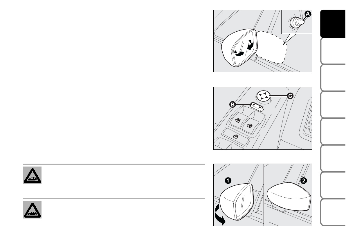
DOOR MIRRORS
Manual adjustment
Use knob (A) to adjust the mirror
Electric adjustment
This operation can be only performed with ignition key to MAR.
Proceed as follows:
❒ use switch (B) to select the mirror required (left or right);
❒ to adjust the mirror move the switch (C) in the four directions.
Adjust mirrors with car stationary and handbrake on.
Mirror defrosting, where provided, starts automatically when switching
the heated rear window on.
Folding
When required (for example when the mirror causes difficulty in narrow
spaces) it is possible to fold mirrors moving them from position (1) to
position (2).
79
SAFETY
DEVICES
CORRECT USE
OF THE CAR
WARNING
LIGHTS AND
MESSAGES
IN AN
EMERGENCY
CAR
MAINTENANCE
TECHNICAL
SPECIFICATIONS
INDEX
DASHBOARD
AND CONTROLS
F0H0058m
F0H0059m
When driving the mirrors shall always be in position (1).
As the driver’s door mirror is curved, it may slightly alter
the perception of distance.
F0H0244m
Page 81

HEATING/CLIMATE CONTROL SYSTEM
80
SAFETY
DEVICES
CORRECT USE
OF THE CAR
WARNING
LIGHTS AND
MESSAGES
IN AN
EMERGENCY
CAR
MAINTENANCE
TECHNICAL
SPECIFICATIONS
INDEX
DASHBOARD
AND CONTROLS
1 Fixed vents for defrosting/demisting side windows - 2 Side adjustable outlets - 3 Fixed vents for
defrosting/demisting windscreen - 4 Centre adjustable outlets - 5 Lower vents - 6 Lower vents for rear passengers.
F0H0060m
Page 82

CENTRAL AND SIDE VENTS
(A) Fixed vents for defrosting/demisting side windows
(B) Control for outlet opening/closing
(C) Control for directing outlet and air flow.
81
SAFETY
DEVICES
CORRECT USE
OF THE CAR
WARNING
LIGHTS AND
MESSAGES
IN AN
EMERGENCY
CAR
MAINTENANCE
TECHNICAL
SPECIFICATIONS
INDEX
DASHBOARD
AND CONTROLS
F0H0061m
F0H0062m
Page 83

CONTROLS
(A) fan activation and speed control knob
(B) air temperature knob (mixing hot and cold
air)
(C) heated rear window on/off button
(D) air distribution knob
(E) air recirculation on/off button.
AIR DISTRIBUTION
Using knob (D) it is possible to choose
manually 5 of the possible air distributions to
the passenger compartment:
« air flow from centre and side vents (2) and
(4);
Δ air flow from centre and side vents (2) and
(4) and downwards (5) and (6) (bilevel
function);
≈ air flow downwards (5) and (6);
HEATING AND VENTILATION
ƒ air flow downwards (5) and (6) and also to the windscreen (3);
-to demist and defrost windscreen (3) and front side windows
(1).
TEMPERATURE ADJUSTMENT
Proceed as follows:
Turn knob (B) clockwise (pointer to red sector) to increase
temperature or turn it counter-clockwise to decrease
temperature;
82
SAFETY
DEVICES
CORRECT USE
OF THE CAR
WARNING
LIGHTS AND
MESSAGES
IN AN
EMERGENCY
CAR
MAINTENANCE
TECHNICAL
SPECIFICATIONS
INDEX
DASHBOARD
AND CONTROLS
F0H0063m
Page 84

FAN SPEED ADJUSTMENT
Proceed as follows:
❒ open completely central (4) and side (2) vents;
❒ turn knob (B) to the blue sector;
❒ set (A) to the required speed;
❒ set knob (D) to «;
❒ set knob (E) to Ú to turn air recirculation off
RECIRCULATION
Set knob (E) to ….
This function is particularly useful when the outside air
is heavily polluted (in a traffic jam, tunnel, etc.).
However, it is better not to use it for long periods,
especially if there are several people in the car to
prevent window steaming up.
IMPORTANT The inside air recirculation system
makes it possible to reach the required “heating” or
“cooling” conditions faster. Do not use the air
recirculation function on rainy/cold days as it would
considerably increase the possibility of the windows
misting inside.
83
SAFETY
DEVICES
CORRECT USE
OF THE CAR
WARNING
LIGHTS AND
MESSAGES
IN AN
EMERGENCY
CAR
MAINTENANCE
TECHNICAL
SPECIFICATIONS
INDEX
DASHBOARD
AND CONTROLS
Page 85

QUICK HEATING
Proceed as follows:
❒ close all dashboard vents;
❒ turn knob (B) to the red sector;
❒ turn knob (A) to 4 -;
❒ turn knob (D) to ≈.
QUICK WINDSCREEN AND FRONT SIDE
WINDOW DEMISTING/DEFROSTING
Proceed as follows:
❒ turn knob (B) to the red sector;
❒ turn knob (A) to 4 -;
❒ turn knob (D) to -;
❒ set knob (E) to U to turn air recirculation off.
After demisting/defrosting, operate normal controls to
restore the required comfort.
Preventive demisting procedure
In the event of considerable outside moisture and/or
rain and/or considerable differences in temperature
inside and outside the passenger compartment,
perform the following preventive demisting procedure:
❒ set knob (E) to U to turn air recirculation off;
❒ knob pointer B in the red section;
❒ turn knob (A) to 2;
❒ turn knob (D) to - or to ƒ if the windows do
not mist up.
REAR WINDOW AND ELECTRIC DOOR
MIRROR DEMISTING/DEFROSTING
(where provided)
Press button (C) to turn this function on. When this
function is on, the button led turns on.
This function is timed and switches off automatically
after the preset time. To cut out this function press
again button (C).
IMPORTANT Do not apply stickers on the inside of
the rear window over the heating filaments to avoid
damage that might cause it to stop working properly.
84
SAFETY
DEVICES
CORRECT USE
OF THE CAR
WARNING
LIGHTS AND
MESSAGES
IN AN
EMERGENCY
CAR
MAINTENANCE
TECHNICAL
SPECIFICATIONS
INDEX
DASHBOARD
AND CONTROLS
Page 86

CONTROLS
(A) fan activation and speed control knob
(B) air temperature knob (mixing hot and cold air)
(C) heated rear window on/off button
(D) climate control compressor on/off button;
(E) air distribution selection knob
(F) air recirculation on/off button.
MANUAL CLIMATE CONTROL SYSTEM (where provided)
AIR DISTRIBUTION
Using knob (E) it is possible to choose
manually 5 of the possible air distributions to
the passenger compartment:
« air flow from central vents and side outlets
(2) and (4);
Δ air flow from centre and side vents (2) and
(4) and downwards (5) and (6) (bilevel
function);
≈ air flow downwards (5) and (6);
ƒ air flow downwards (5) and (6) and also to
the windscreen (3);
-to demist and defrost windscreen (3) and
front side windows (1).
85
SAFETY
DEVICES
CORRECT USE
OF THE CAR
WARNING
LIGHTS AND
MESSAGES
IN AN
EMERGENCY
CAR
MAINTENANCE
TECHNICAL
SPECIFICATIONS
INDEX
DASHBOARD
AND CONTROLS
F0H0064m
Page 87

TEMPERATURE ADJUSTMENT
Proceed as follows:
Turn knob (B) clockwise (pointer to red sector) to
increase temperature or turn it counter-clockwise to
decrease temperature;
FAN SPEED ADJUSTMENT
Proceed as follows:
❒ open completely central (4) and side (2) vents;
❒ turn knob (B) to the blue sector;
❒ set (A) to the required speed;
❒ set knob (E) to «;
❒ set knob (F) to U to turn air recirculation off.
RECIRCULATION
Set knob (F) to ….
This function is particularly useful when the outside air
is heavily polluted (in a traffic jam, tunnel, etc.).
However, it is better not to use it for long periods,
especially if there are several people in the car to
prevent window steaming up.
IMPORTANT The inside air recirculation system
makes it possible to reach the required “heating” or
“cooling” conditions faster. Do not use the air
recirculation function on rainy/cold days as it would
considerably increase the possibility of the windows
misting inside.
QUICK HEATING
Proceed as follows:
❒ close all dashboard vents;
❒ turn knob (B) to the red sector;
❒ turn knob (A) to 4 -;
❒ turn knob (E) to ≈.
86
SAFETY
DEVICES
CORRECT USE
OF THE CAR
WARNING
LIGHTS AND
MESSAGES
IN AN
EMERGENCY
CAR
MAINTENANCE
TECHNICAL
SPECIFICATIONS
INDEX
DASHBOARD
AND CONTROLS
Page 88

QUICK WINDSCREEN AND FRONT SIDE
WINDOW DEMISTING/DEFROSTING
Proceed as follows:
❒ turn knob (B) to the red sector;
❒ turn knob (A) to 4 -;
❒ turn knob (E) to -;
❒ set knob (F) to U to turn air recirculation off.
After demisting/defrosting, operate the controls to
restore the required comfort.
Preventive demisting procedure
In the event of considerable outside moisture and/or
rain and/or considerable differences in temperature
inside and outside the passenger compartment,
perform the following preventive demisting procedure:
❒ set knob (F) to U to turn air recirculation off;
❒ turn knob (B) to the red sector;
❒ turn knob (A) to 2;
❒ turn knob (E) to - or to ƒ if the windows do not
mist up.
IMPORTANT Climate control is very useful to speed
up window demisting: therefore, perform demisting
procedure as described previously and then switch the
system on pressing button (D).
REAR WINDOW AND ELECTRIC DOOR
MIRROR DEMISTING/DEFROSTING
(where provided)
Press button (C) to turn this function on. When this
function is on, the button led turns on.
This function is timed and switches off automatically
after the preset time. To cut out this function press
again button (C).
IMPORTANT Do not apply stickers on the inside of
the rear window over the heating filaments to avoid
damage that might cause it to stop working properly.
87
SAFETY
DEVICES
CORRECT USE
OF THE CAR
WARNING
LIGHTS AND
MESSAGES
IN AN
EMERGENCY
CAR
MAINTENANCE
TECHNICAL
SPECIFICATIONS
INDEX
DASHBOARD
AND CONTROLS
Page 89

CLIMATE CONTROL (cooling and
dehumidification)
Proceed as follows:
❒ turn knob (B) to the blue sector to select
temperature;
❒ turn knob (A) to the required speed;
❒ set knob (E) to «;
❒ set knob (F) to ….
❒ press (D) √ (button led will turn on).
Cooling adjustment
Proceed as follows:
❒ set knob (F) to U to turn air recirculation off;
❒ turn knob (B) to the right to raise temperature;
❒ turn knob (A) to the left to reduce the fan speed.
LOOKING AFTER THE SYSTEM
During the winter, the climate control system must be
turned on at least once a month for about ten
minutes. Before summer, have the system checked at a
Fiat Dealership.
88
SAFETY
DEVICES
CORRECT USE
OF THE CAR
WARNING
LIGHTS AND
MESSAGES
IN AN
EMERGENCY
CAR
MAINTENANCE
TECHNICAL
SPECIFICATIONS
INDEX
DASHBOARD
AND CONTROLS
Page 90

AUTOMATIC TWO-ZONE CLIMATE CONTROL SYSTEM (where provided)
GENERAL
The car is fitted with a two-zone climate control
system which makes it possible to separately adjust the
air temperature on the driver’s side and on the
passenger’s side. Temperature control is based on the
“equivalent temperature” logic, i.e.: the system
continuously works to keep constant the comfort
inside the passenger compartment and to compensate
any variation of the outside climate conditions,
including sunshine detected by a proper sensor
provided for the purpose.
The climate control system automatically controls and
adjusts the following parameters and functions:
❒ air temperature at driver/front passenger vents;
❒ air distribution at driver/front passenger vents;
❒ fan speed (continuous air flow variation);
❒ compressor switching on (to cool/dehumidify air);
❒ air recirculation.
All the above functions can be changed manually at any
time, i.e.: you can always modify one or more function
settings. In this event, the system will no longer
implement the automatic control of the functions
changed manually (except for safety reasons, e.g.: risk
of window misting).
Manual selections prevail over automatic ones and
remain in storage until the user decides to resume
automatic control, except when the system cuts in for
particular safety conditions.
The control of functions not changed manually remains
automatic.
The amount of air admitted to the passenger
compartment does not depend on the car speed, since
it is electronically controlled by the fan.
In any case, the temperature of the air admitted to the
passenger compartment is controlled automatically
(except when the system is off) according to the
temperatures set on the driver’s and front passenger’s
displays or under certain climatic conditions if the
compressor is off).
89
SAFETY
DEVICES
CORRECT USE
OF THE CAR
WARNING
LIGHTS AND
MESSAGES
IN AN
EMERGENCY
CAR
MAINTENANCE
TECHNICAL
SPECIFICATIONS
INDEX
DASHBOARD
AND CONTROLS
Page 91

The system enables to set or to change the
following parameters and functions manually:
❒ air temperatures on driver/front passenger
side;
❒ fan speed (continuous variation);
❒ air distribution on five levels (driver/front
passenger side);
❒ climate control compressor on/off enable;
❒ monozone/two-zone distribution priority;
❒ fast demisting/defrosting;
❒ air recirculation;
❒ rear heated window;
❒ system off;
CONTROLS
(A) MONO function button (for aligning set
temperatures)
(B) climate control compressor on/off button
(C) inside air recirculation on/off button
(D) display showing climate control system
data
(E) climate control system off button
(F) MAX-DEF function button (front window fast
defrosting/demisting)
(G) rear window heating on/off button
(H) AUTO function button (automatic mode) and knob to adjust
temperature on passenger side
(I) buttons for air distribution on passenger side
(L) button for adjusting fan speed
(M) button for air distribution on driver side
(N) AUTO function button (automatic mode) and knob to adjust
temperature on driver side
90
SAFETY
DEVICES
CORRECT USE
OF THE CAR
WARNING
LIGHTS AND
MESSAGES
IN AN
EMERGENCY
CAR
MAINTENANCE
TECHNICAL
SPECIFICATIONS
INDEX
DASHBOARD
AND CONTROLS
F0H0065m
Page 92

SWITCHING THE CLIMATE
CONTROL SYSTEM ON
The system can be started in different ways, but it is
advisable to press one of the AUTO buttons and then
to turn the knobs to set the temperatures required on
the display.
It is possible to personalise required temperatures
(driver and passenger) with a maximum difference of 7
°C.
This way the system will start working completely
automatically to reach the temperatures set as quickly
as possible. The system will adjust the air temperature,
flow and distribution and will control the air
recirculation function and the conditioner compressor
on/off.
During fully automatic operation, the only manual
settings required are the following:
❒ MONO, to align the air temperature and
distribution set on the passenger’s side (front or
rear) with that on the driver’s side;
❒ …, air recirculation, to keep it always on or off;
❒ -, to speed up demisting/defrosting of
windscreen, front side windows, rear window and
door mirrors;
❒ (, to demist/defrost the rear heated window and
the door mirrors.
During completely automatic system operation, the
temperatures, air distribution and the fan speed set
can be changed at any time through the relevant
buttons or knobs: the system will automatically change
its settings to adjust to the new requirements.
During full automatic operation (FULL AUTO), any
change in air distribution and/or air flow and/or
compressor turning on and/or air recirculation will
obtain FULL disappearing. In this way functions will be
controlled manually until pressing the AUTO button
again. The fan speed is the same for all passenger
compartment areas.
With one or more functions engaged manually, the
adjustment of the temperature of the air admitted to
the passenger compartment continues to be
controlled automatically by the system, except with
the climate control compressor off. In fact, in this
condition, the air admitted to the passenger
compartment cannot have a lower temperature than
the outside air.
91
SAFETY
DEVICES
CORRECT USE
OF THE CAR
WARNING
LIGHTS AND
MESSAGES
IN AN
EMERGENCY
CAR
MAINTENANCE
TECHNICAL
SPECIFICATIONS
INDEX
DASHBOARD
AND CONTROLS
Page 93

CONTROLS
Air temperature
adjustment knobs H-N
Turning the knobs
clockwise or
counterclockwise,
highers or lowers the temperature of the air required
respectively in the left zone (knob N) or right zone
(knob H) of the passenger compartment.
It is possible to personalise required temperatures
(driver and passenger) with a maximum difference of 7
°C.
The temperatures set are shown on the displays near
the relevant knobs.
Pressing button A (MONO) automatically aligns the
temperature on the front passenger’s side with that on
the driver’s side. It is therefore possible to set the
same temperature between the two zones simply
turning the knob on the driver’s side (N).
This function is provided to simplify temperature
adjustment of the whole passenger compartment when
only the driver is on board.
Separate operation of the set temperatures is
automatically restored by turning knobs (H) or
pressing button A (MONO) again when the button led
is on.
Turning the knobs clockwise or counterclockwise until
they reach the extreme selections HI or LO, the
maximum heating or cooling functions are respectively
engaged:
❒ HI function (highest heating power):
this is activated by turning the temperature knob
clockwise above the max. value (32 °C). It can be
activated independently from the driver’s or
passenger’s side or both (also selecting the MONO
function).
This function can be engaged when requiring to heat
the passenger compartment as quickly as possible,
exploiting the maximum potential of the system. This
function uses the maximum temperature of the
coolant fluid, while air distribution and fan speed are
controlled according to the system settings.
More particularly, max. fan speed will not be
immediately engaged if coolant is not hot enough; this
to prevent admitting air that is not warm enough to
the passenger compartment.
All manual settings are however possible with this
function on.
92
SAFETY
DEVICES
CORRECT USE
OF THE CAR
WARNING
LIGHTS AND
MESSAGES
IN AN
EMERGENCY
CAR
MAINTENANCE
TECHNICAL
SPECIFICATIONS
INDEX
DASHBOARD
AND CONTROLS
Page 94

To switch the function off, simply turn the
temperature knob counterclockwise and set the
required temperature.
❒ LO function (highest cooling power):
this is activated by turning the temperature knob
counterclockwise below the min. value (16 °C). It can
be activated independently from the driver’s or
passenger’s side or both (also selecting the MONO
function).
This function can be engaged when requiring to cool
the passenger compartment as quickly as possible,
exploiting the maximum potential of the system. This
function engages inside air recirculation and climate
control compressor, while air distribution and fan
speed are controlled according to environmental
conditions. All manual settings are however possible
with this function on.
To switch the function off, simply turn the
temperature knob clockwise and set the required
temperature.
Front air distribution
selection buttons
(I-M)
Pressing the relevant
buttons it is possible to
manually choose one of the five possible air
distributions to the left and right side of the passenger
compartment:
▲
Air flow to the windscreen and front side window
vents to demist or defrost them.
˙
Air flow to dashboard central and side vents to provide satisfactory ventilation to the chest and face,
specially during the summer.
▼
Air flow towards the front and rear lower parts of
the passenger compartment. Due to the natural tendency of heat to spread upwards, this type of distribution allows heating of the passenger compartment
in the shortest time, also giving a prompt feeling of
warmth to the coldest parts of the body.
˙
▼
Splitting of the air flow between the vents to the
lower part of the passenger compartment (warmest
air) and the dashboard centre and side outlets
(coolest air). This air flow distribution is particularly useful in spring and autumn, when the sun is
shining.
▲
▼
Splitting of the air flow between the lower part of
the passenger compartment and the windscreen and
front side window demisting/defrosting vents. This
type of air distribution allows satisfactory heating of
the passenger compartment while preventing possible misting of the windows.
93
SAFETY
DEVICES
CORRECT USE
OF THE CAR
WARNING
LIGHTS AND
MESSAGES
IN AN
EMERGENCY
CAR
MAINTENANCE
TECHNICAL
SPECIFICATIONS
INDEX
DASHBOARD
AND CONTROLS
Page 95

Set air flow distribution is indicated by the
corresponding button led switching on.
With a combined function set, pressing a button will
turn on the main function of the button pressed,
together with the functions set yet. Pressing the
button of the active function will turn the function off
(led off).
To restore automatic air distribution control after a
manual selection, press button AUTO.
When the driver selects air distribution towards the
windscreen, also the air distribution on passenger’s
side will automatically be directed to the windscreen.
The passenger can however select a different air
distribution by pressing the relevant buttons.
Fan speed adjustment buttons (L)
Pressing the ends of button p
increases or decreases the fan speed
and therefore the amount of air
admitted to the passenger
compartment, although keeping the required
temperature.
The fan speed is shown by the lit bars on the display
❒ max fan speed = all bars lit
❒ min fan speed = one bar lit.
The fan can be cut off only if the climate control
compressor has been switched off pressing button B.
IMPORTANT To restore automatic fan speed control
after a manual adjustment, press button AUTO.
94
SAFETY
DEVICES
CORRECT USE
OF THE CAR
WARNING
LIGHTS AND
MESSAGES
IN AN
EMERGENCY
CAR
MAINTENANCE
TECHNICAL
SPECIFICATIONS
INDEX
DASHBOARD
AND CONTROLS
Page 96

Air recirculation is controlled
according to the following operating
logics:
❒ forced switching on (air recirculation
always on), indicated by the turning
on of the led on button (C) and
symbol í on the display;
❒ forced switching off (air recirculation always off
with air inlet from the outside), indicated by the
turning off of the button led and êon the
display.
AUTO buttons
(H-N)
(automatic
operation)
Pressing the AUTO
button (on driver and/or front passenger side) the
system automatically adjusts the amount and
distribution of the air admitted to the passenger
compartment, cancelling all the previous manual
adjustments.
This condition is indicated by the message FULL
AUTO on the front system display.
Manual operation of at least one automatic function
(air recirculation, air distribution, fan speed or climate
control compressor off) will cause FULL message
going off the display. This means that automatic
control is not complete (except temperature control
which is always automatic).
IMPORTANT Should the system (after manual
settings) be no longer able to guarantee the required
temperature set in the passenger compartment, the
set temperature value will start flashing to indicate this
condition, after one minute the AUTO message will
turn off.
To restore automatic system control after one or
more manual selections, press button AUTO.
MONO button (A) (alignment of
set temperatures and air
distribution)
Pressing button MONO automatically
aligns the temperature on the front
passenger’s side with that on the driver’s side. It is
therefore possible to set the same temperature and air
distribution between the two zones simply turning the
knob on the driver’s side. This function is provided to
simplify temperature adjustment of the whole
passenger compartment when only the driver is on
board. Separate operation of the set temperatures and
air distribution is automatically restored by turning
knob (H) or pressing button MONO (A) again when
the button led is on.
Air recirculation on/off button (C)
95
SAFETY
DEVICES
CORRECT USE
OF THE CAR
WARNING
LIGHTS AND
MESSAGES
IN AN
EMERGENCY
CAR
MAINTENANCE
TECHNICAL
SPECIFICATIONS
INDEX
DASHBOARD
AND CONTROLS
Page 97
These operating conditions are obtained pressing in
sequence the air recirculation button (C).
After a preset time, the climate control system will
turn air recirculation off automatically for safety
reasons, thus enabling outside air inlet.
IMPORTANT The air recirculation system
makes it possible to reach the required heating or
cooling conditions faster.
It is however inadvisable to use it on rainy/cold days as
it would considerably increase the possibility of the
windows misting inside, especially if the climate
control system is off.
When the outside temperature is below 5-7°C, air
recirculation is switched off (air is taken from the
outside) to prevent misting.
96
SAFETY
DEVICES
CORRECT USE
OF THE CAR
WARNING
LIGHTS AND
MESSAGES
IN AN
EMERGENCY
CAR
MAINTENANCE
TECHNICAL
SPECIFICATIONS
INDEX
DASHBOARD
AND CONTROLS
WARNING
It is inadvisable to use the air recirculation feature with low outside temperature
as the windows might mist over quickly.
Page 98

Climate control compressor
on/off button (B)
Press the
√
button, when the button
led is on, to switch the compressor off.
The led will go off. By pressing again
the button when the led is off, the system automatic
control of the compressor activation is restored; this
condition is indicated by button led lighting up.
When the air conditioner compressor is off, the
system deactivates air recirculation to prevent window
misting up. Although the system is still able to maintain
the required temperature, the message FULL on the
display will go off. If the system is no longer able to
keep the required temperature, also the message
AUTO will turn off.
IMPORTANT Air at a temperature lower than that of
the outside air cannot be let into the passenger
compartment when the compressor is off.
Furthermore, in particular environmental conditions,
the windows could mist up fast because the air is no
longer dehumidified.
Setting will be stored also when the engine is stopped.
Either press again button
√
(in this case the system
operates as heater only) or AUTO to reset automatic
control of the compressor.
With compressor off, if the outside temperature is
higher than the set temperature, the system cannot
reach the required temperature. This will be signalled
by the flashing of set temperature value on the display
for a few seconds, then the message AUTO will go off.
When the compressor is off, it is possible to reset
manually the fan speed (no bar displayed).
When the compressor is on and the engine is running,
fan speed cannot be lower than the minimum (one bar
displayed).
97
SAFETY
DEVICES
CORRECT USE
OF THE CAR
WARNING
LIGHTS AND
MESSAGES
IN AN
EMERGENCY
CAR
MAINTENANCE
TECHNICAL
SPECIFICATIONS
INDEX
DASHBOARD
AND CONTROLS
Page 99

Button for fast windscreen and
front side window
demisting/defrosting (F)
Press this button: the climate control
system will automatically switch on all
the functions required for fast windscreen and front
side window demisting/defrosting, that is:
❒ climate control system compressor on (with
proper climatic conditions);
❒ air recirculation off;
❒ maximum air temperature (HI) on both areas;
❒ fan speed according to engine coolant temperature
in order to limit letting cold air into the passenger
compartment for demisting the windows;
❒ air flow directed to the windscreen and front side
window vents;
❒ heated rear window
IMPORTANT The fast windscreen
demisting/defrosting function stays on for approx. 3
minutes after the engine coolant temperature exceeds
50°C (petrol versions) or 35°C (Multijet versions).
When the max. demisting/defrosting function is on, the
led on the relevant button and that on the heated rear
window button turn on. Message FULL AUTO on the
display will turn off.
When the max. demisting/defrosting function is on, the
only manual operations possible are manual
adjustment of the fan and switching rear window
heating off.
Press button (F) or air recirculation button (C) or
compressor button (B) or AUTO buttons (N o H) to
reset the previous system operation conditions.
98
SAFETY
DEVICES
CORRECT USE
OF THE CAR
WARNING
LIGHTS AND
MESSAGES
IN AN
EMERGENCY
CAR
MAINTENANCE
TECHNICAL
SPECIFICATIONS
INDEX
DASHBOARD
AND CONTROLS
Page 100

Button for demisting/defrosting
the heated rear window and door
mirrors (G)
Press this button to switch on the
heated rear window
demisting/defrosting function. The led on the button
will come on.
This function will be automatically switched off after
the preset time, or pressing the button again or when
stopping the engine. It will not start up automatically
when the engine is started again.
IMPORTANT Do not apply stickers on the inside of
the rear window over the heating filaments to avoid
damage that might cause it to stop working properly.
❒ climate control system compressor off;
❒ fan off.
The heated rear window can be switched on and off
normally when the system is off by pressing button
(G).
IMPORTANT The climate control system electronic
unit stores the system settings made before the
system was switched off and restores them as soon as
a button is pressed (with the exception of the heated
rear window button). The function which the button
corresponds to will be switched on, if it was off when
the system was switched off. It will be kept if, on the
other hand, it was on when the system was switched
off.
Press the AUTO button to switch the climate control
system back on.
99
SAFETY
DEVICES
CORRECT USE
OF THE CAR
WARNING
LIGHTS AND
MESSAGES
IN AN
EMERGENCY
CAR
MAINTENANCE
TECHNICAL
SPECIFICATIONS
INDEX
DASHBOARD
AND CONTROLS
OFF button (E) (system off)
To switch the climate control system
off, press button (E), also the display
will go off.
The climate control system conditions
when the system is off are the following:
❒ Every led off;
❒ set temperatures not displayed;
❒ air recirculation on, thus isolating the passenger
compartment;
 Loading...