

Page 1
Originalbedienungsanleitung/Ersatzteilliste 6 - 9
Original operating manual/Spare parts list 10 - 13
Notice d’utilisation d’origine/Liste de pièces de rechange 14 - 18
Manual de instrucciones original/Lista de piezas de repuesto 18 - 22
Istruzioni per l’uso originali/Elenco parti di ricambio 23 - 36
Originele gebruiksaanwijzing/Lijst met reserveonderdelen 27 - 31
Originalbruksanvisning/Reservdelslista 31 - 35
Alkuperäiset käyttöohjeet/Varaosaluettelo 35 - 38
Original brugsanvisning/Reservedelsliste 39 - 42
Originalbruksanvisning/Reservedelsliste 43 - 46
Manual de instruções original/Lista de peças sobresselentes 47 - 50
Оригинал Руководства по эксплуатации/Перечень запасных частей 51 - 55
Originální návod k použití/Seznam náhradních dílů 55 - 58
Oryginalna instrukcja eksploatacji/Lista części zamiennych 59 - 62
TDK 12
TDK 15.6
468003_002
Page 2

Page 3

Page 4
1.4
1.3
1.5 1.6 1.7
1.2
1.1
1
Page 5
BF-FX
2.1 2.5
2.2 2.3 2.4
DD-AS
DD-ES
WH-CE
2
2.6
2.8
2.7
2.9 2.10 2.11
3
3.1
3.2
4.2 4.3 4.44.1
4
Page 6

Technische Daten Akku-Bohrschrauber TDK 12 TDK 15.6
Motorspannung 12 V 15,6 V
Leerlaufdrehzahl 1. Gang 0 - 430 min
2. Gang 0 - 1400 min
-1
0 - 450 min-1
-1
0 - 1500 min-1
Drehmoment max.
weicher Schraubfall (Holz) 20 Nm 25 Nm
harter Schraubfall (Metall) 28 Nm 36 Nm
Drehmoment einstellbar 1. Gang 2 - 7 Nm 2 - 7 Nm
2. Gang 0,5 - 2,5 Nm 0,5 - 2,5 Nm
Bohrfutter-Spannbereich 1,5 - 13 mm 1,5 - 13 mm
max. Bohrdurchmesser in Holz 25 mm 35 mm
max. Bohrdurchmesser in Metall 14 mm 16 mm
Werkzeugaufnahme in Bohrspindel 1/4 “ 1/4 “
Gewicht mit Akku 2,0 kg 2,3 kg
Ladegerät LC 45
Netzspannung (Eingang) 230 -240 V~
Netzfrequenz 50/60 Hz
Ladespannung (Ausgang) 7,2 - 18 V=
Ladestrom 3 A
Schnellladung max. 3 A
Erhaltungsladung pulsierend ca. 0,06 A
Ladezeit für NiCd 2,0 Ah ca. 45 min
NiCd 2,4 Ah ca. 50 min
NiMH 3,0 Ah ca. 70 min
Akkupack BPS 12 S NiCd BPS 12 S NiMH
Bestellnummer 492 268 491 821
Spannung 12 V 12 V
Kapazität 2,4 Ah 3,0 Ah
Ladetemperaturbereich 5 - 45° C 5 - 45° C
Temperaturüberwachung m i t t e l s N T C - W i d e r s t a n d
Gewicht 0,73 kg 0,75 kg
Akkupack BPS 15.6 S NiCd BPS 15.6 S NiMH
Bestellnummer 492 269 491 823
Spannung 15,6 V 15,6 V
Kapazität 2,4 Ah 3,0 Ah
Ladetemperaturbereich 5 - 45° C 5 - 45° C
Temperaturüberwachung m i t t e l s N T C - W i d e r s t a n d
Gewicht 0,9 kg 0,92 kg
Die angegebenen Abbildungen befi nden sich am Anfang dieser Bedienungsanleitung.
1 Vor Inbetriebnahme beachten
1.1 Bestimmungsgemäße Verwen-
dung
Die Akku-Bohrschrauber sind zum Bohren in
Metall, Holz, Kunststoffen und ähnlichen Materialien geeignet, sowie zum Festschrauben und
Einschrauben von Schrauben (bis Durchmesser
6 mm in Holz). Das Ladegerät LC 45 ist zum Aufladen der aufgeführten Akkupacks bestimmt.
Für Schäden und Unfälle bei nicht be-
stimmungsgemäßem Gebrauch haftet
der Benutzer.
b) Maschinenspezifi sche Sicherheits-
hinweise
- Ladegerät und Elektrowerkzeug sind nicht
dafür bestimmt, durch Personen (einschließlich Kinder) mit eingeschränkten physischen,
sensorischen oder geistigen Fähigkeiten oder
mangels Erfahrung und/oder mangels Wissen
benutzt zu werden, es sei denn, sie werden
durch eine für ihre Sicherheit zuständige
Person beaufsichtigt oder erhielten von ihr
Anweisungen, wie das Ladegerät bzw. Elektrowerkzeug zu benutzen ist. Kinder sollten
beaufsichtigt werden, um sicherzustellen,
1.2 Sicherheitshinweise
a) Allgemeine Sicherheitshinweise
Lesen Sie vor Gebrauch der Maschine
die beiliegenden Sicherheitshinweise
und die Bedienungsanleitung aufmerk-
sam und vollständig durch.
Bewahren Sie alle beiliegenden Dokumente auf
und geben Sie die Maschine nur zusammen mit
diesen Dokumenten weiter.
dass sie nicht mit dem Ladegerät oder Elektrowerkzeug spielen.
- Fassen Sie die Maschine nur an isolierten
Grifffl ächen an, wenn Sie Arbeiten ausführen,
bei denen das Werkzeug verborgene Stromleitungen treffen kann.
- Achten Sie beim Bohren in Wände auf eventuell vorhandene Gas-, Strom- oder Wasserleitungen.
6
Page 7

- Öffnen Sie den Akkupack und das Ladegerät
nicht. Im Inneren des Ladegerätes steht auch
nach der Trennung vom Netz eine hohe Kondensatorspannung an.
- Achten Sie darauf, dass am Ladegerät in die
Aufnahmen der Akkupacks und durch die
Lüftungsschlitze keine Metallteile (z. B. Metallspäne) ins Geräteinnere gelangen (Kurzschlussgefahr).
- Schützen Sie den Akkupack vor Hitze z. B.
auch vor dauernder Sonneneinstrahlung und
Feuer. Es besteht Explosionsgefahr.
2.3 Getriebeumschaltung
Nur im Stillstand schalten!
Mit Schaltschieber (1.5) wird das Getriebe geschaltet.
1. Gang:
Schaltschieber nach vorn - Ziffer 1 ist sichtbar.
2. Gang:
Schaltschieber nach hinten - Ziffer 2 ist sichtbar.
2.4 Drehmomenteinstellung
Durch Verdrehen des Stellrings (1.6) kann das
Drehmoment eingestellt werden. Die Markierung
1.3 Lärm- und Vibrationsinformation
Akku-Bohrschrauber
Die nach EN 60745 ermittelten Werte betragen
typischerweise:
Schalldruckpegel 72 dB(A)
Schallleistungspegel 83 dB(A)
Messunsicherheitszuschlag K = 4 dB
Beim Arbeiten kann der Geräuschpegel
(1.7) zeigt den eingestellten Zustand an.
Bohren
Markierung zeigt auf Bohrersymbol = maximales Drehmoment.
Schrauben
Drehmoment entsprechend Einstellung:
Stellung auf 1 = kleines Drehmoment
Stellung auf 20 = hohes Drehmoment
85 dB(A) überschreiten.
Gehörschutz tragen!
3 Werkzeugaufnahme, Vorsatzaggre-
gate
Schwingungsemissionswert a
(Vektorsumme
h
dreier Richtungen) und Unsicherheit K ermittelt
nach EN 60745:
Bohren in Metall a
< 2,5 m/s²
h
K = 1,5 m/s²
Schrauben a
< 2,5 m/s²
h
K = 1,5 m/s²
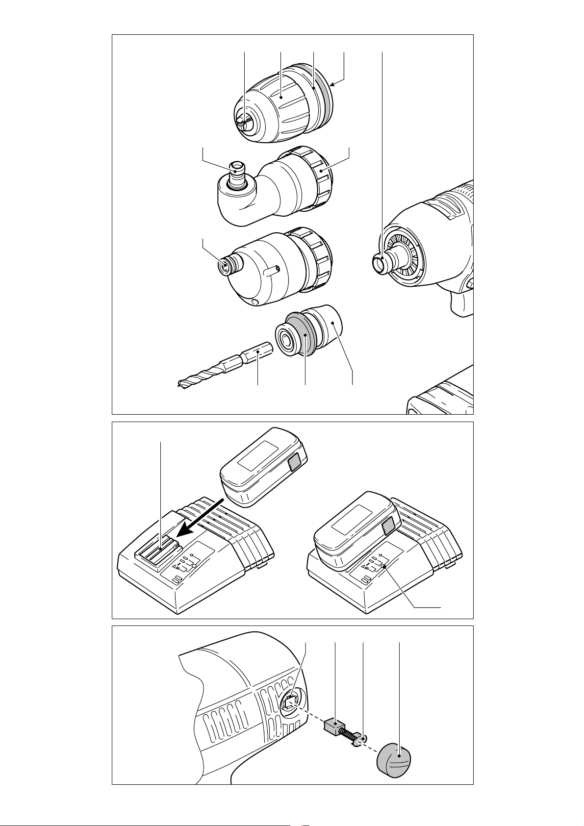
3.1 Bohrfutter BF-FX
Das Bohrfutter dient zum Einspannen von Bohrern und Bits.
a) Bohrfutter montieren/demontieren
Montage
- Setzen Sie das Bohrfutter auf die Bohrspindel
(2.5) auf und verdrehen Sie es so weit, bis
der Sechskantstift (2.4) des Bohrfutters in
1.4 Wandbefestigung LC 45
Das Ladegerät LC 45 besitzt an seiner Rückseite
zwei Langlöcher, wodurch es mithilfe von zwei
Schrauben (z. B. Halbrund- oder Flachkopfschraube mit Schaftdurchmesser 5 mm) an
einer Wand aufgehängt werden kann.
Schrauben Sie hierfür die beiden Schrauben
im Abstand von 96 mm so weit in die Wand,
dass der Schraubenkopf noch ca. 4 mm von
der Wand absteht.
die Innensechskantaufnahme der Bohrspindel
einrastet.
- Ziehen Sie den Entriegelungsring (2.3) nach
vorne, drücken Sie das Bohrfutter bis zum
Anschlag auf die Bohrspindel und lassen Sie
den Entriegelungsring los.
Demontage
- Ziehen Sie den Entriegelungsring nach vorne
und nehmen Sie das Bohrfutter ab.
b) Werkzeug wechseln
- Drehen Sie die Spannhülse (2.2) gegen den
2 Einstellungen an der Maschine
Vor jeglicher Einstellung, Instandhaltung oder
Instandsetzung Akkupack entfernen!
2.1 Akkupack wechseln
Akkupack abnehmen
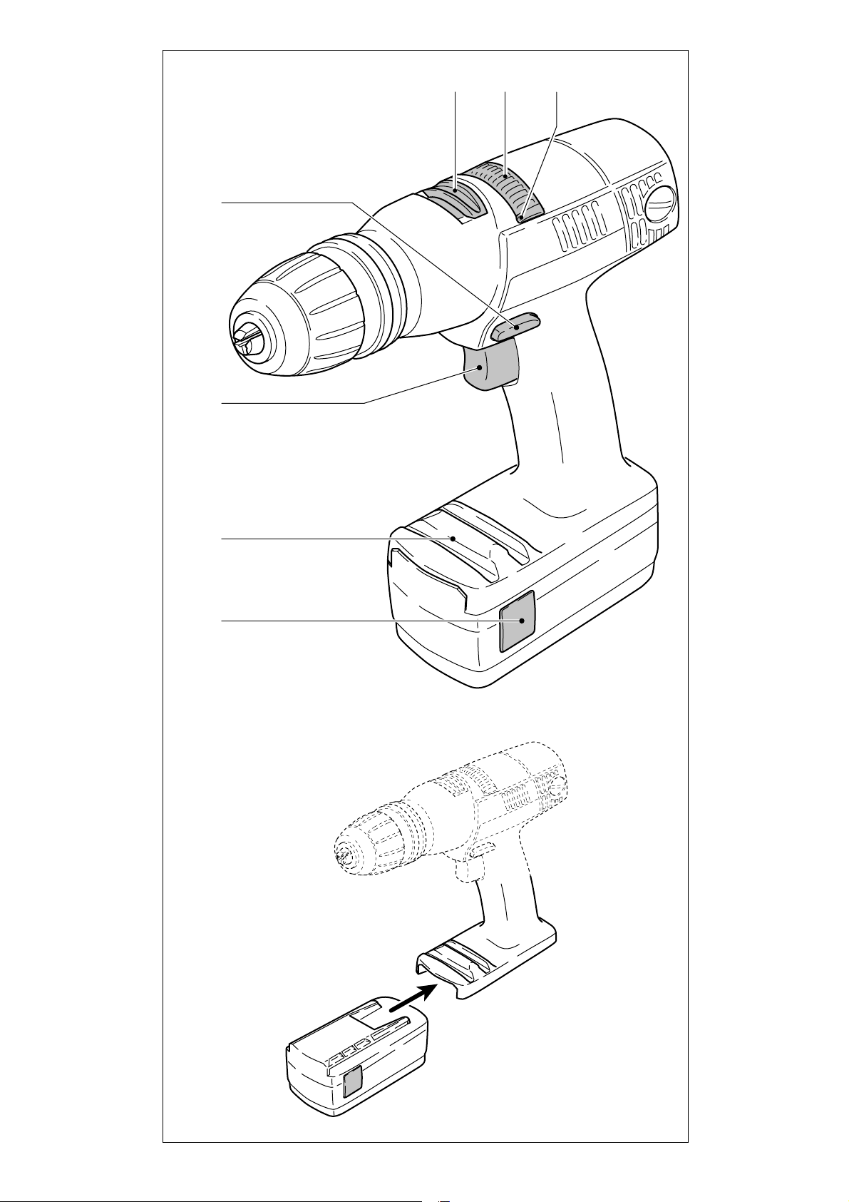
Drücken Sie die beiden Tasten (1.1) und nehmen Sie den Akkupack nach vorne hin ab.
Uhrzeigersinn, um die Spannbacken (2.1) zu
öffnen (Hinweis: Bei ausgeschalteter Maschine ist die Spindel automatisch arretiert).
- Setzen Sie das Werkzeug in das Bohrfutter
ein.
- Spannen Sie das Werkzeug fest, indem Sie
die Spannhülse im Uhrzeigersinn drehen.
Achten Sie immer darauf, dass das Werkzeug
zentrisch im Bohrfutter gespannt ist.
Akkupack einsetzen
Schieben Sie den Akkupack bis zum Einrasten
auf die Halterung an der Griffunterseite (siehe
Bild 1).
2.2 Umschalten der Drehrichtung
Der Schaltknopf (1.4) ist zur Bestimmung der
Drehrichtung. Knopf von rechts nach links gedrückt = Rechtslauf; Knopf von links nach
rechts gedrückt = Linkslauf;
Knopf in Mittelstellung = Einschaltsperre.
3.2 Winkelvorsatz DD-AS
Der Winkelvorsatz ermöglicht ein Arbeiten
(Bohren, Schrauben) senkrecht zur Längsachse
der Maschine.
a) Winkelvorsatz montieren/demon-
tieren
Montage
- Setzen Sie den Winkelvorsatz auf die Bohr-
spindel auf und verdrehen Sie ihn so weit,
bis er in der gewünschten Position einrastet
(Hinweis: Der Winkelvorsatz lässt sich in 16
verschiedenen Winkelstellungen einrasten).
7
Page 8
- Verriegeln Sie den Winkelvorsatz, indem Sie
den Befestigungsring (2.7) im Uhrzeigersinn
fest drehen.
Demontage
- Drehen Sie den Befestigungsring gegen den
Uhrzeigersinn bis zum Anschlag und nehmen
Sie den Winkelvorsatz ab.
b) Bohrfutter auf Winkelvorsatz mon-
tieren/demontieren
Das Bohrfutter wird in gleicher Weise auf die
Welle (2.6) des Winkelvorsatzes befestigt wie
auf die Bohrspindel der Maschine.
3.3 Exzentervorsatz DD-ES
Der Exzentervorsatz dient zur Aufnahme von
Bits. Er ermöglicht ein Rand nahes Schrauben.
a) Exzentervorsatz montieren/de-
montieren
Die Montage/Demontage des Exzentervorsatzes
erfolgt in gleicher Weise wie die des Winkelvorsatzes (siehe Kapitel 3.2).
b) Werkzeug wechseln
- Ziehen Sie den Entriegelungsring (2.8) zurück
und entnehmen Sie das Werkzeug bzw. setzen
Sie ein Werkzeug ein.
3.4 Werkzeughalter CENTROTEC WH-CE
Der Werkzeughalter CENTROTEC ermöglicht
einen schnellen Wechsel von Werkzeugen mit
CENTROTEC-Schaft.
Spannen Sie CENTROTEC Werkzeuge
nicht am runden Schaftteil in einem
herkömmlichen Bohrfutter, damit der
Schaft nicht beschädigt wird.
Verletzungsgefahr! Handhaben Sie
das Werkzeug mit seinen scharfen
Schneiden beim Werkzeugwechsel mit
besonderer Vorsicht und tragen Sie ggf.
Schutzhandschuhe.
a) CENTROTEC montieren/demontieren
Montage
- Ziehen Sie den Entriegelungsring (2.11) nach
vorne, setzen Sie den Werkzeughalter bis zum
Anschlag auf die Bohrspindel (2.5) und lassen
Sie den Entriegelungsring los.
Demontage
- Ziehen Sie den Entriegelungsring nach vorne
und nehmen Sie den Werkzeughalter ab.
4 Akkupack laden
Zum Laden ist der Akkupack bis zum Anschlag
auf die Halterung (3.1) des Ladegerätes zu
schieben. In entgegengesetzter Richtung kann
der geladene Akkupack dem Ladegerät entnommen werden. Der eingesetzte Akkutyp (NiCd
oder NiMH) wird automatisch erkannt.
Der Ladevorgang wird mittels Mikroprozessor
gesteuert. Wird ein warmer NiMH-Akkupack
(>37° C) eingesetzt, wird nur mit reduziertem
Ladestrom geladen. In diesem Fall verlängert
sich die Ladezeit.
Die LED (3.2) zeigt den jeweiligen Betriebszustand des Ladegerätes an.
LED gelb - Dauerlicht:
Ladegerät ist betriebsbereit.
LED grün - Blinklicht:
Akkupack wird geladen.
LED grün - Dauerlicht:
Akkupack ist aufgeladen, Erhaltungsladung
läuft.
LED rot - Blinklicht:
allgemeine Fehleranzeige, z. B.: keine voll-
ständige Kontaktierung, Kurzschluss, Akkupack defekt.
LED rot - Dauerlicht:
Akkutemperatur außerhalb zulässiger Grenz-
werte.
Beachten Sie unbedingt die Hin-
weise im Kapitel „Arbeitshinweise
- Wartung - Pfl ege“.
5 Arbeiten mit der Maschine
5.1 Inbetriebnahme
Einschalten durch Drücken der Schaltertaste
(1.3). Je nach Druck auf die Schaltertaste, ist
die Drehzahl stufenlos steuerbar. Ausschalten
durch Loslassen der Schaltertaste (1.3). Nach
dem Loslassen der Schaltertaste wird die Arbeitsspindel (Bohrfutter) abgebremst und damit
ein Nachlaufen des Werkzeugs verhindert.
5.2 Bit-Depot
In das Bit-Depot (1.2) lassen sich mehrere Bits
oder Bitverlängerungen seitlich einschieben.
Durch die magnetische Halterung können auch
Schrauben und ähnliche Gegenstände aufgenommen werden.
b) Werkzeug wechseln
- Ziehen Sie zum Einsetzen bzw. Entnehmen
eines Werkzeuges mit CENTROTEC-Schaft
den grünen Entriegelungsring (2.10) zurück.
Verdrehen Sie beim Einsetzen das Werkzeug
bis dessen Sechskantschaft (2.9) in die Sechskantaufnahme der Bohrspindel einrastet und
schieben Sie das Werkzeug bis zum Anschlag
in den Werkzeughalter.
3.5 Werkzeugaufnahme in der Bohr-
spindel
Damit die Maschine leichter und kürzer wird,
können Bits direkt in der Innensechskantaufnahme der Bohrspindel (2.5) eingesetzt werden.
6 Arbeitshinweise - Wartung - Pfl ege
Bitte beachten Sie die nachfol-
genden Hinweise. Ansonsten besteht die Gefahr einer Schädigung
der Maschine, des Ladegerätes oder
des Akkupacks.
- Reparaturen dürfen nur vom Fachmann ausgeführt werden. Beim Ladegerät LC 45 steht
auch nach der Trennung vom Netz am Leistungsteil im Innern des Gerätes eine hohe
Kondensatorspannung an.
- Lüftungsöffnungen am Elektrowerkzeug und
am Ladegerät sauber halten, damit Luftzirkulation zur Kühlung gewährleistet ist.
- Am Ladegerät dürfen in die Aufnahmen der
Akkupacks und durch die Lüftungsschlitze hin-
8
Page 9

durch ins Geräteinnere keine Metallteile (z. B.
Metallspäne) gelangen (Kurzschlussgefahr).
- Verwenden Sie nur originale Festool-Akkupacks. Verwenden Sie keine gebrauchten und
wieder aufbereiteten Akkupacks. Für Schäden
bei Verwendung von nicht originalen FestoolAkkupacks haftet der Benutzer.
- Anschlusskontakte am Elektrowerkzeug, Ladegerät und Akkupack sauber halten.
- Durch die Aufbewahrung des Akkupacks im
betriebsbereiten Ladegerät wird der Akkupack
durch ständige Erhaltungsladung im aufgeladenen Zustand gehalten.
- Leere Akkupacks nicht länger als ca. 1 Monat im Ladegerät stecken lassen, wenn das
Ladegerät vom Netz getrennt ist (Gefahr der
Tiefentladung).
- Ein neuer, oder längere Zeit nicht gebrauchter,
Akkupack erreicht erst nach ca. 5 Lade- und
Entladezyklen seine volle Kapazität.
- Akkupacks sollten vor dem erneuten Aufl aden
möglichst vollständig entladen werden. Wiederholter Start des Ladevorgangs bei geladenem Akku verringert dessen Lebensdauer.
- Eine wesentlich verkürzte Betriebszeit je
Aufl adung zeigt an, dass der Akkupack ver-
braucht ist und durch einen neuen ersetzt
werden muss.
- NiCd-Akkupacks, die längere Zeit nicht benutzt werden, sollten im entladenen Zustand
aufbewahrt werden.
Besondere Hinweise für NiMH-Akkupacks:
- Bei Umgebungstemperatur unter 0° C oder
über 45° C nimmt die Leistung von NiMH-Akkupacks spürbar ab.
- Maschine nicht überlasten (Maschine nicht so
stark beanspruchen, dass diese zum Stillstand
kommt).
- NiMH-Akkupacks auch bei Nichtbenutzung
ca. alle 4 Monaten erneut aufl aden, um deren
volle Kapazität zu erhalten.
- NiMH-Akkupacks sollten nach ca. jedem 10.
Ladevorgang nach der Schnellladung noch
für eine Stunde im Ladegerät verbleiben, um
mögliche Kapazitätsunterschiede zwischen
den Zellen auszugleichen.
- NiMH-Akkupacks aufgrund der Selbstentladung vorzugsweise bei Umgebungstem-peraturen zwischen 0° C und 25° C lagern.
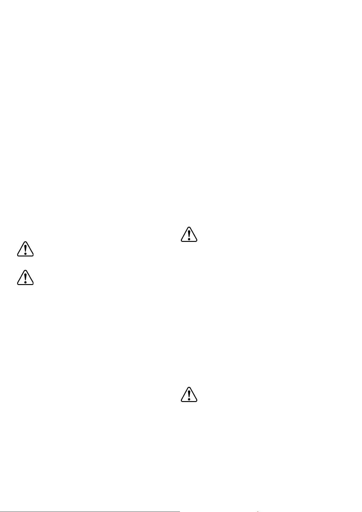
6.1 Kohlewechsel
Sind die Kohlen auf eine Restlänge kleiner 6 mm
abgenützt, kann sich die Leistung der Maschine
verringern oder der Motor aussetzen. In diesem
Fall sind die Kohlen (4.2) zu wechseln.
- Schrauben Sie die Abdeckung (4.4) ab und
entnehmen Sie die alten Kohlen.
- Drücken Sie das Halteblech (4.3) der neuen
Kohlen bis zum Einrasten in die Aussparungen
(4.1), ehe Sie die Abdeckung wieder aufschrauben.
- Betreiben Sie die Maschine für einige Minuten
im Leerlauf, damit die neuen Kohlen optimalen
Kontakt bekommen.
7 Recycling von Akkupacks
Werfen Sie den verbrauchten Ak-
kupack nicht in den Hausmüll!
Geben Sie verbrauchte oder defekte Akkupacks
über den Fachhandel, den Festool-Kundendienst
oder öffentlich vorgeschriebene Entsorgungseinrichtungen zurück. Die Akkupacks werden so
einem geordneten Recycling zugeführt.
8 Gewährleistung
Für unsere Geräte leisten wir auf Material- oder
Fertigungsfehler Gewährleistung gemäß den
länderspezifi schen gesetzlichen Bestimmungen,
mindestens jedoch 12 Monate. Innerhalb der
Staaten der EU beträgt die Gewährleistungszeit
24 Monate (Nachweis durch Rechnung oder
Lieferschein). Schäden, die insbesondere auf
natürliche Abnützung/Verschleiß, Überlastung,
unsachgemäße Behandlung bzw. durch den
Verwender verschuldete Schäden oder sonstige
Verwendung entgegen der Bedienungsanleitung
zurückzuführen sind oder beim Kauf bekannt
waren, bleiben von der Gewährleistung ausgeschlossen. Ebenso ausgeschlossen bleiben
Schäden, die auf die Verwendung von nicht-originalem Festool Zubehör und Verbrauchmaterial
(z. B. Schleifteller) zurückzuführen sind. Beanstandungen können nur anerkannt werden,
wenn das Gerät unzerlegt an den Lieferanten
oder an eine autorisierte Festool-Kundendienstwerkstätte zurückgesendet wird. Bewahren Sie
Bedienungsanleitung, Sicherheitshinweise, Ersatzteilliste und Kaufbeleg gut auf. Im übrigen
gelten die jeweils aktuellen Gewährleistungsbedingungen des Herstellers.
Anmerkung
Aufgrund der ständigen Forschungs- und Entwicklungsarbeiten sind Änderungen der hierin
gemachten technischen Angaben vorbehalten.
9 EG-Konformitätserklärung
Wir erklären in alleiniger Verantwortung, dass
dieses Produkt mit den folgenden Normen oder
normativen Dokumenten übereinstimmt:
EN 60745, EN 60335-2-29, EN 55014,
EN 61000 gemäß den Bestimmungen der
Richtlinien 2006/95/EG, 98/37/EG (bis 28.
Dez. 2009), 2006/42/EG (ab 29. Dez. 2009),
2004/108/EG.
Dr. Johannes Steimel
Leiter Forschung und Entwicklung
Festool GmbH, Wendlingen
9
Page 10

Technical data
Cordless drill/screwdriver TDK 12 TDK 15.6
Motor voltage 12 V 15.6 V
Idle-running speed 1. Speed 0 - 430 rpm 0 - 450 rpm
2. Speed 0 - 1400 rpm 0 - 1500 rpm
Max torque
Soft boring (wood) 20 Nm 25 Nm
Hard boring (metal) 28 Nm 36 Nm
Adjustable torque
1. Speed 2 - 7 Nm 2 - 7 Nm
2. Speed 0.5 - 2.5 Nm 0.5 - 2.5 Nm
Chuck capacity 1.5 - 13 mm 1.5 - 13 mm
Max. drill diameter for wood 25 mm 35 mm
Max. drill diameter for metal 14 mm 16 mm
Tool fi tting in chuck 1/4 “ 1/4 “
Weight with battery pack 2.0 kg 2.3 kg
Charger LC 45
Supply voltage (input) 230 - 240 V~
Line frequency 50/60 Hz
Charging voltage (output) 7.2 - 18 V=
Charging current 3 A
Quick charge max. 3 A
Compensation charge pulsating app. 0.06 A
Charging time for NiCd 2.0 Ah app. 45 min
NiCd 2.4 Ah app. 50 min
NiMH 3.0 Ah app. 70 min
Battery pack BPS 12 S NiCd BPS 12 S NiMH
Order number 492 268 491 821
Voltage 12 V 12 V
Capacity 2.4 Ah 3.0 Ah
Temp. range for charging 5 - 45° C 5 - 45° C
Temperature monitoring u s i n g N T C r e s i s t o r
Weight 0.73 kg 0.75 kg
Battery pack BPS 15.6 S NiCd BPS 15.6 S NiMH
Order number 492 269 491 823
Voltage 15.6 V 15.6 V
Capacity 2.4 Ah 3.0 Ah
Temp. range for charging 5 - 45° C 5 - 45° C
Temperature monitoring u s i n g N T C r e s i s t o r
Weight 0.9 kg 0.92 kg
The specifi ed illustrations can be found at the beginning of the operating instructions.
1 Before starting up, please observe
the following
1.1 Intended use
Cordless drills are suitable for drilling metal,
wood, plastics and similar materials, as well as
tightening and screwing in screws (into wood,
up to a diameter of 6 mm). The LC 45 battery
charger is designed for recharging the battery
pack listed.
The user is liable for damage and injury
resulting from incorrect usage!
1.2 Safety instructions
a) General Safety Rules
Before using the machine, read the
enclosed safety instructions and these
operating instructions carefully and
thoroughly.
Save all enclosed documents and pass the machine with all these documents only.
b) Machine-related safety instructions
- Charger and power tool are not intended
for use by persons (including children) with
limited physical, sensory or mental ability or
without suffi cient experience and/or know-
ledge, unless they are supervised by a person responsible for their safety or have been
instructed on how the charger or power tool
is to be used. Children should always be supervised to ensure that they do not play with
the charger or the power tools.
- Always hold the machine by the insulated
handles if there is a possibility of drilling into
hidden power cables.
- Take care when drilling into walls as there is
10
Page 11

a danger of rupturing concealed gas/water
pipes or cutting through power cables.
- Do not open the battery pack or the charger.
Even after disconnection from the mains,
there is still a high capacitor voltage inside
the charger.
- Make sure that metal objects (such as metal
chips) do not collect in the battery pack retaining slots or enter the machine through the
air vent slits (danger of short circuit).
- Protect the battery pack from excessive heat
or constant heat sources such as sunlight or
naked fl ames. There is a risk of explosion.
1.3 Noise and vibration information
Cordless drill/screwdriver
The typical values determined in accordance
with EN 60745 are:
Sound pressure level 72 dB(A)
Sound-power level 83 dB(A)
Measuring uncertainty allowance K = 4 dB
The noise level can exceed 85 dB(A)
during operation.
Wear ear protection!
Vibration emission value a
(vector sum for
h
three directions) and uncertainty K measured
in accordance with EN 60745:
Drilling in metal a
< 2,5 m/s²
h
K = 1,5 m/s²
Screws a
< 2,5 m/s²
h
K = 1,5 m/s²
1.4 Wall mounting LC 45
The charger LC 45 has two longitudinal slots on
its rear by which it can be suspended on walls
using two screws (e.g. button-headed or fl at
head screw with a shaft diameter of 5 mm).
Screw both screws into the wall 96 mm apart
until the screwhead is protruding from the wall
by approx. 4 mm.
2 Machine settings
Remove the battery pack before any adjustments, maintenance or repair is carried out!
2.1 Exchanging the battery pack
Removing battery pack
Press the two buttons (1.1) and slide the battery pack forwards to remove.
Inserting battery pack
Slide the battery pack into the holder on the
underside of the handle until it latches into
place (see Fig. 1).
2.2 To change the direction of rotati-
on
The selector button (1.4) determines the direction of rotation. Turn button from right to left =
clockwise rotation. Turn button from left to
right = anticlockwise rotation. Selector button in central position = circuit interlock.
2.3 Shifting speeds
Change only when completely stop-
ped!
Using the shift lever (1.5), the speed can be
changed.
1. Speed: Lever forward - Figure 1 is visible.
2. Speed: Lever backwards - Figure 2 is vi-
sible.
2.4 Torque adjustment
By turning the adjustment ring (1.6) the required torque can be adjusted. The arrow (1.7)
aligns with the adjusted state.
Drilling
Drilling symbol on adjustment ring aligns with
the arrow = maximum torque.
Screws
Torque corresponding to setting:
Position 1 = low torque
Position 20 = high torque
3 Tool holding fi xture, attachments
3.1 Chuck BF-FX
The chuck is used to clamp drills and bits.
a) Fitting/removing the chuck
Fitting
- Place the chuck on the drill spindle (2.5) and
twist until the hexagon key (2.4) of the chuck
latches into the hexagon socket of the drill
spindle.
- Pull the unlocking ring (2.3) forwards, press
the chuck onto the drill spindle up to the stop
and release the unlocking ring.
Removal
- Pull the unlocking ring forwards and remove
the chuck.
b) Changing tools
- Turn the clamping sleeve (2.2) anti-clockwise
to open the clamping jaws (2.1) (Note: the
spindle is automatically locked when the machine is switched off).
- Insert the tool into the chuck.
- Clamp the tool by turning the clamping sleeve
clockwise. Always make sure that the tool is
clamped centrally in the chuck.
3.2 Angle attachment DD-AS
The angle attachment permits work (drilling,
screwing) vertical to the machine’s longitudinal
axis.
a) Fitting/removing the angle attach-
ment
Fitting
- Place the angle attachment on the drill spindle
and turn until it catches in the desired position
(Note: The angle attachment can be fi tted in
16 different angle settings).
- Lock the angle attachment by turning the
fastening ring (2.7) tightly clockwise.
Removal
- Turn the fastening ring anti-clockwise up to
the stop and remove the angel attachment.
11
Page 12
b) Fitting/removal of chuck on angle
attachment
The chuck is fi tted on the shaft (2.6) of the
angle attachment in the same way as on the
drill spindle of the machine.
3.3 Eccentric attachment DD-ES
The eccentric attachment is used to hold bits.
It allows screwing close to edges.
a) Fitting/removing the eccentric at-
tachment
The eccentric attachment is fi tted/removed in
the same was as the angle attachment (see
Chapter 3.2).
b) Changing tools
- Pull the unlocking ring (2.8) back and remove
the tool and/or insert the new tool.
3.4 CENTROTEC WH-CE toolholder
The CENTROTEC toolholder enables rapid
changes of tools with CENTROTEC shafts.
Do not fi t CENTROTEC tools at the round
shaft section in a conventional chuck to
prevent damage to the shaft.
Danger of injury! When changing
tools, handle the tool and its sharp
cutters with special care and wear protective gloves, if necessary.
a) Fitting/removing CENTROTEC
Fitting
- Pull the release ring (2.11) forwards, place
the toolholder as far as it will go on the drill
spindle (2.5) and let go of the release ring.
Removal
- Pull the release ring forwards and take off the
toolholder.
b) Changing tools
- To insert or remove a tool with CENTROTEC
shaft, pull the green release ring (2.10) back.
On inserting the tool, turn it until its hex shank
arbour (2.9) locks in place in the hexagonal
shank of the drill spindle, and push the tool
into the toolholder as far as it will go.
3.5 Tool holding fixture in the drill
spindle
Bits can be fi tted directly in the hexagon socket
holder of the drill spindle (2.5) to make the
machine lighter and shorter.
4 Charge battery pack
To load the battery pack, push it into the holder
(3.1) on the charger up to the stop. Perform this
in reverse to remove the battery pack from the
charger. The battery type used (NiCd or NiMH)
is detected automatically. Charging is controlled
by a microprocessor. If a warm NiMH battery
pack (>37° C) is inserted, charging will only be
carried out at a lower charge current. In this
case, the charging time is extended.
The LED (3.2) indicates the respective
charging state of the charger.
LED yellow – steady:
Charger is ready for use.
LED green – fl ashing:
Battery pack being charged.
LED green – steady:
Battery pack fully charged, conservation char-
ge on.
LED red – fl ashing:
General malfunction, e. g. full contact not
being made, short-circuit, battery pack faulty.
LED red – steady:
Temperature of battery pack is outside per-
missible limit.
It is essential that you read the
instructions in the Chapter „Working instructions - Maintenance
- Care“.
5 Working with the machine
5.1 Initial operation
Turn on by pressing button (1.3). Depending on
the pressure exerted on the button, the adjustment of running speed can be varied infi nitely.
Turn off by releasing the button (1.3).
After releasing the button, the chuck is stopped
and therefore, after-running of the equipment
is prevented.
5.2 Bit storage well
You can insert several bits or bit extensions into
the bit magazine (1.2) from the side.
The magnetic attachment allows you to pick up
screws and similar objects.
6 lnstructions on application - main-
tenance - care
Please pay attention to the fol-
lowing instructions. Otherwise there is a risk of damage to the tool,
charger or battery pack.
- Repairs may only be performed by authorised
technicians. LC 45 charging device: Even after
disconnection from the mains, there is still a
high capacitor voltage on the power output
component on the inside of the device.
- Keep the air vents of the electronic equipment
and the charger clean to guarantee the air
circulation for cooling.
- No metal objects (metal chips) should enter
the charger at the contact points as well as
through the cooling slits into the equipment
(danger of short circuit).
- Only use original Festool battery packs.
Do not use spent and recycled battery packs.
The user shall be liable for damages if Festool
original battery packs are not used.
- Keep the connection contacts of electronic
equipment, charger and battery pack clean.
12
Page 13

- By keeping the battery pack in a ready for use
charger, the battery pack will be kept in a state
of readiness by fl oat charging conservation.
- Do not keep discharged battery pack (maximum one month) attached to charger whenever charger is detached from the power supply
(danger of deep discharging).
- A new battery pack or a battery pack not used
for a longer period of time reaches it full capacity after about 5 charging and discharging
cycles.
- Battery packs should, before charging, be fully
discharged if possible.
Continuous starting of the charging process
shortens the lifespan of the batteries.
- A considerably reduced time of operation per
charging shows that the battery pack is used
up an should be replaced by a new one.
- NiCd battery packs that are not used for longer periods should be stored in a discharged
state.
Special instructions for NiMH battery
packs:
- The output of NiMH battery packs drops noticeably at ambient temperatures below 0° C
or above 45° C.
- Do not overload the tool (do not load the tool
excessively so that it comes to a standstill).
- Even if NiMH battery packs are not used, recharge them approx. every 4 months so that
they retain their full capacity.
- NiMH battery packs should be left for 60 min.
in the charger after every 10th fast charge
to compensate any differences in capacity
between the cells.
- Because NiMH battery packs discharge automatically, store them preferably at ambient
temperatures of between 0° C and 25° C.
7 Recycling battery packs
Never throw spent battery packs
into domestic waste containers!
Return spent or defective battery packs to dealers, the Festool after-sales service department
or approved waste disposal facilities. This ensures that they are correctly recycled.
8 Warranty
Our equipment is under warranty for at least 12
months with regard to material or production
faults in accordance with national legislation.
In the EU countries, the warranty period is 24
months (an invoice or delivery note is required
as proof of purchase). Damage resulting from,
in particular, normal wear and tear, o-verloading, improper handling, or caused by the user
or other damage caused by not following the
operating instructions, or any fault acknowledged at the time of purchase, is not covered
by the warranty. Damage caused by the use
of non-original accessories and consumable
material (e.g. sanding pads) is also excluded.
Complaints will only be acknowledged if the
equipment has not been dismantled before
being sent back to the suppliers or to an authorised Festool customer support workshop.
Store the operating instructions, safety notes,
spare parts list and proof of purchase in a safe
place. In addition, the manufacturer‘s current
warranty conditions apply.
Note
We reserve the right to make changes to the
technical data contained in this infor-mation as
a result of ongoing research and development
work.
6.1 Changing carbon brushes
If the carbon brushes have worn to a length of
less than 6 mm, this may reduce the performance of the machine or cause the machine
to stop. In this case, the brushes (4.2) should
be replaced.
- Unscrew the cover (4.4) and remove the worn
brushes.
- Push in the retaining plate (4.3) on the new
carbon brushes until it latches into the notches
(4.1) and screw the covers back on.
- Operate the machine in idling state for a few
minutes so that the carbon brushes attain
optimal contact.
9 EU Declaration of Conformity
We declare under sole responsibility that this
product complies with the following norms or
normative documents:
EN 60745,EN 60335-2-29, EN 55014,
EN 61000 in accordance with the regulations
stipulated in Directive 2006/95/EC, 98/37/EC
(until 28 Dec. 2009), 2006/42/EC (from 29 Dec.
2009), 2004/108/EC.
Dr. Johannes Steimel
Head of research and development
Festool GmbH, Wendlingen, Germany
13
Page 14

Données techniques
Perceuses-visseuses à accumulateur TDK 12 TDK 15.6
Tension du moteur 12 V 15,6 V
Vitesse à vide 1ère vitesse 0 - 430 tr/min 0 - 450 tr/min
2ème vitesse 0 - 1400 tr/min 0 - 1500 tr/min
Couple de rotation max.
Cas de vissage
dans un matériau tendre (bois) 20 Nm 25 Nm
dans un matériau dur (métal) 28 Nm 36 Nm
Réglage de couple 1ère vitesse 2 - 7 Nm 2 - 7 Nm
2ème vitesse 0,5 - 2,5 Nm 0,5 - 2,5 Nm
Capacité mandrin 1,5 - 13 mm 1,5 - 13 mm
Maxi capacité de perçage dans du bois 25 mm 35 mm
Maxi capacité de perçage dans du métal 14 mm 16 mm
Raccordement d’outil
dans la broche de perçag 1/4 “ 1/4 “
Poids avec accumulateur 2,0 kg 2,3 kg
Chargeur LC 45
Tension secteur (entrée) 230 - 240 V~
Fréquence secteur 50/60 Hz
Tension de charge (sortie) 7,2 - 18 V=
Courant de charge 3 A
Charge rapide 3 A max.
Charge de maintien à impulsions, environ 0,06 A
Durée de charge pour NiCd 2,0 Ah 45 min. env.
NiCd 2,4 Ah 50 min. env.
NiMH 3,0 Ah 70 min. env.
Accumulateur BPS 12 S NiCd BPS 12 S NiMH
Référence 492 268 491 821
Tension 12 V 12 V
Capacité 2,4 Ah 3,0 Ah
Plage de température de charge 5 - 45° C 5 - 45° C
Contrôle de la température au moyen d’un rhéostat NTC
Poids 0,73 kg 0,75 kg
Accumulateur BPS 15.6 S NiCd BPS 15.6 S NiMH
Référence 492 269 491 823
Tension 15,6 V 15,6 V
Capacité 2,4 Ah 3,0 Ah
Plage de température de charge 5 - 45° C 5 - 45° C
Contrôle de la température au moyen d’un rhéostat NTC
Poids 0,9 kg 0,92 kg
Les illustrations indiquées se trouvent au début du mode d’emploi.
1 A respecter avant la mise en ser-
vice
1.1 Utilisation conforme
La perceuse-visseuse sans fi l est adaptée au
perçage du métal, du bois, des plastiques et
matériaux similaires, ainsi qu’au vissage (vis
jusqu’à un diamètre de 6 mm dans le bois).
Le chargeur LC 45 convient au chargement de
la batterie utilisée.
L’utilisateur est responsable des dégâts
ou accidents qu’il peut provoquer en
ne respectant pas les dispositions de
sécurité.
1.2 Informations de sécurité
a) Indications générales de sécurité
Avant l’utilisation de la machine, lisez
attentivement et intégralement les
consignes de sécurité et les instructions
d’utilisation ci-jointes.
Conserver précieusement tous les documents
fournis. En cas de cession de la machine, les
donner au nouveau propriétaire.
b) Consignes de sécurité spécifi ques
à la machine
- Ce chargeur et cet outil électrique ne sont pas
appropriés pour une utilisation par des personnes (y compris enfants) ayant des facultés
physiques, sensorielles ou intellectuelles limi-
14
Page 15
tées ou par manque d‘expérience et/ou manque de connaissances, à moins d‘être sous la
surveillance d‘une personne responsable pour
leur sécurité ou d‘avoir eu de cette personne
des instructions sur l‘utilisation du chargeur
ou de l‘outil électrique. Les enfants devraient
rester sous surveillance, afi n de s‘assurer
qu‘ils ne jouent pas avec le chargeur ou l‘outil
électrique.
- Tenez la machine uniquement au niveau des
surfaces isolées de la poignée lorsque vous
effectuez des travaux au cours desquels l'outil
risque de toucher des câbles électriques cachés.
- Lors du perçage dans le murs, faites attention
à d'éventuelles conduites de gaz, de courant
électrique ou d'eau.
- N'ouvrez pas la batterie, ni le chargeur. La tension au condensateur à l'intérieur du chargeur
reste élevée même après le débranchement
du réseau.
- Assurez-vous qu'aucune particule métallique
(p. ex. copeaux métalliques) ne puisse parvenir dans le chargeur au niveau du logement de
la batterie, ni à travers les fentes d'aération
(risque de court-circuit).
- Protégez la batterie contre la chaleur, p. ex.
également contre les rayons de soleil permanents ou le feu. Il y a risque d'explosion.
1.3 Informations concernant le bruit et
les vibrations
Perceuses-visseuses à accumulateur
Les valeurs typiques obtenues selon EN 60745
sont les suivantes
Niveau de pression de bruit 72 dB(A)
Niveau de puissance sonore 83 dB(A)
Majoration pour incertitude
de mesure K = 4 dB
Le niveau de bruit de 85 dB(A) peut être
dépassé pendant le travail.
Munissez-vous de casques anti-
bruit!
2 Réglages de la machine
La batterie doit être retirée avant chaque opération de réglage, d’entretien ou de remise en
état !
2.1 Remplacer la batterie
Retrait de la batterie
appuyez sur le deux touches (1.1), et enlevez
la batterie en la tirant vers l’avant.
Installation de la batterie
enfoncez la batterie dans le logement par le
dessous de la poignée jusqu’à ce qu’elle soit
bien enclenchée (voir schéma 1).
2.2 Commutation du sens de rotation
Le bouton de commutation (1.4) sert à déterminer le sens de rotation. Bouton poussé de
droite vers la gauche = marche à droite.
Bouton poussé de gauche vers la droite = mar-
che à gauche. Bouton en position centrale =
verrouillage de mise en marche.
2.3 Commutation de l’engrenage
Procéder à la commutation unique-
ment à l’arrêt ou en fi n de roule-
ment!
Le curseur de commutation (1.5) permet de
commuter l’engrenage.
1ère vitesse: Curseur de commutation vers
l’avant - le chiffre 1 est visible.
2ème vitesse: Curseur de commutation vers
l’arrière - le chiffre 2 est visible.
2.4 Réglage du couple de rotation
Il est possible de faire varier le couple de rotation en tournant la bague de réglage (1.6). La
fl èche apposée (1.7) indiquera l’état réglé.
Perçage
Couple de rotation maximal - la fl èche est poin-
tée sur le symbole de perçage
Vissage
Couple de rotation en fonction du réglage:
Position sur 1 = couple de rotation réduit
Position sur 20 = couple de rotation élevé
Valeur d‘émission vibratoire a
(somme vecto-
h
rielle tridirectionnelle) et incertitude K déterminées selon NE 60745 :
Perçage dans le métal a
< 2,5 m/s²
h
K = 1,5 m/s²
Vissage a
< 2,5 m/s²
h
K = 1,5 m/s²
1.4 Fixation au mur LC 45
Le chargeur LC 45 dispose sur son dos de deux
trous oblongs par l’intermédiaire desquels il
peut être fi xé au mur par deux vis (par ex. vis
à tête conique ou ronde avec un diamètre de la
partie lisse de la tige de 5 mm). Vissez les deux
vis en respectant un intervalle de 96 mm au
mur, de manière à ce qu’il reste encore un espace de 4 mm entre la tête de vis et le mur.
3 Porte-outil, groupes d’appui
3.1 Mandrin de perceuse BF-FX
Le mandrin de perceuse sert à serrer les forets
et les embouts.
a) Montage/démontage du mandrin
de perceuse
Montage
- Placez le mandrin de perceuse sur l’axe (2.5)
puis tournez-le jusqu’à ce que le six pans (2.4)
du mandrin de perceuse s’enclenche dans le
logement de l’axe.
- Tirez la bague de déverrouillage (2.3) vers
l’avant, enfoncez le mandrin de perceuse
jusqu’à la butée sur l’axe puis relâchez la
bague de déverrouillage.
Démontage
- Tirez la bague de déverrouillage vers l’avant
puis enlevez le mandrin de perceuse.
15
Page 16

b) Changement d’outil
- Tournez la douille de serrage (2.2) dans le
sens contraire des aiguilles d’une montre
pour ouvrir les mâchoires de serrage (2.1)
(Remarque : A machine inactivée, l’axe est
automatiquement verrouillé).
- Placez l’outil dans le mandrin de perceuse.
- Serrez l’outil à fond en tournant la douille
de serrage dans le sens des aiguilles d’une
montre. Ce faisant, veillez toujours à ce que
l’outil soit serré au centre du mandrin.
3.2 Appui angulaire DD-AS
L’appui angulaire permet de travailler (percer,
visser) à la verticale par rapport à l’axe longitudinal de la machine.
a) Montage/démontage de l’appui
angulaire
Montage
- Placez l’appui angulaire sur l’axe et tournez-le
jusqu’à ce qu’il s’enclenche dans la position
souhaitée (Remarque : L’appui angulaire
peut s’enclencher dans 16 positions angulaires
différentes).
- Verrouillez l’appui angulaire en tournant fermement la bague de fi xation (2.7) dans le
sens des aiguilles d’une montre.
Démontage
- Tournez la bague de fi xation dans le sens
contraire des aiguilles d’une montre jusqu’à
la butée puis enlevez l’appui angulaire.
b) Montage/démontage du mandrin
de perceuse sur l’appui angulaire
Le mandrin de perceuse doit être fi xé de la
même manière sur l’arbre (2.6) de l’appui angulaire que sur l’axe de la machine.
3.3 Appui excentrique DD-ES
L’appui excentrique sert à la réception d’embouts.
Il permet de visser à proximité du bord.
a) Montage/démontage de l’appui
excentrique
Le montage/démontage de l’appui excentrique
s’opère de la même manière que pour l’appui
angulaire (cf. chapitre 3.2).
b) Changement d’outil
- Tirez la bague de déverrouillage (2.8) vers
l’arrière puis enlevez l’outil ou resp. mettez
un outil en place.
3.4 Porte-outil CENTROTEC WH-CE
Le porte-outil CENTROTEC permet un changement rapide d’outils avec arbre CENTROTEC.
Ne serrez pas les outils CENTROTEC
au niveau du manche dans un mandrin de serrage traditionnel pour ne pas
endommager le manche.
Risque de blessure ! Manipulez très
prudemment l’outil aux arêtes tranchantes lorsque vous procédez à un
échange d’outil, portez éventuelle-ment
des gants de protection.
a) Montage/démontage du CENTRO-
TEC
Montage
- Tirez la bague de déverrouillage (2.11) vers
l’avant, enfoncez le porte-outil jusqu’en butée sur l’axe (2.5) puis relâchez la bague de
déverrouillage.
Démontage
- Tirez la bague de déverrouillage vers l’avant
et enlevez le porte-outil.
b) Changement d’outillage
- Pour placer ou enlever un outil avec arbre
CENTROTEC, retirez sur la bague de déverrouillage verte (2.10). Pour mettre un outil
en place, tournez jusqu’à ce que son arbre
hexagonal (2.9) s’engage dans le logement
hexagonal de l’axe et poussez l’outil à fond
dans le porte-outil.
3.5 Porte-outil sur l’axe
Afi n que la machine devienne plus légère et
plus courte, les embouts peuvent être mis en
place directement dans le logement six pans
de l’axe (2.5).
4 Charger l’accumulateur
Pour le chargement, vous devez pousser la
batterie dans le logement (3.1) du chargeur
jusqu’à la butée. A l’inverse, il est possible de
retirer la batterie chargée du chargeur. Le type
d’accumulateur utilisé (NiCd ou NiMH) est identifi é automatique-ment. La procédure de charge
est contrôlée par microprocesseur.
Si vous utilisez un pack d’accumulateurs NiMH
chaud (>37°C), il sera seulement chargé avec
un courant de charge réduit. Dans ce cas, le
temps de charge sera prolongé.
La DEL (3.2) indique à chaque fois l’état
de service du chargeur.
DEL jaune - éclairage continu:
le chargeur est prêt à fonctionner.
DEL verte - éclairage clignotant:
L’accumulateur est en train d’être chargé.
DEL verte - éclairage continu:
L’accumulateur est chargé; la charge de main-
tien est active.
DEL rouge - éclairage clignotant:
indication d’erreur générale, par exemple pas
de mise en contact complète, court-circuit,
défectuo-sité de l’accumulateur
DEL rouge - éclairage continu:
température del’accumulateur au-delà des
valeurs limites admissibles.
Nous vous recommandons de re-
specter les instructions décrites
dans le chapitre intitulé „Instructions d’utilisation - Entretien Maintenance“.
5 Travail avec la machine
5.1 Mise en service
Mise en marche en appuyant sur la touche de
commutation (1.3). La vitesse de rotation peut
être progressivement réglée, en fonction du
mode de pression sur la touche de commutation. Mise à l’arrêt en relâchant la touche de
commutation (1.3). Une fois que la touche de
commutation est relâchée, la broche de travail
(mandrin) est freinée, ce qui empêche ainsi une
poursuite de rotation par inertie de l’outil.
16
Page 17

5.2 Bit-Depot
Dans le porte-embouts (1.2), il est possible
d’insérer latéralement plusieurs embouts ou
rallonges pour embouts. Le logement magnétique permet également de recevoir des vis et
objets similaires.
6 Informations de travail - Entre-
tien - Maintenance
Il est indispensable d’observer les
consignes suivantes, sinon, la machine, le chargeur ou l’accumulateur risque d’être endommagé(e).
- Les réparations doivent être uniquement réalisées par un spécialiste. Dans le chargeur LC
45, la tension au condensateur à l’intérieur de
l’appareil reste élevée même après le débranchement du réseau.
- Veiller à ce que les ouvertures d’aération sur
l’outil électrique et sur le chargeur soient toujours propres afi n que la circulation de l’air de
refroidissement soit assurée.
- Sur le chargeur, aucune pièce métallique
(copeaux métalliques) ne doit pénétrer dans
les compartiments de réception des accumulateurs et par les fentes d’aération (risque de
court-circuit).
- N’utiliser que des accumulateurs d’origine
Festool et ne pas utiliser non plus
d’accumulateurs usagés ou remis en état. En
effet, seul l’utilisateur sera tenu responsable
en cas d’apparition de dommages résultant
d’une violation de cette prescription.
- Veiller à ce que les contacts de raccordement
sur l’outil électrique, sur le chargeur et sur
l’accu-mulateur soient toujours propres.
- En laissant l’accumulateur dans le chargeur
prêt à fonctionner, l’accumulateur est conservé en état chargé grâce à un charge-ment de
maintien permanent.
- Ne pas laisser les accumulateurs vides enfi chés pendant plus d’un mois env. dans le
chargeur lorsque le chargeur est coupé du
secteur (risque de décharge profonde).
- Un accumulateur neuf ou n’ayant pas été
utilisé pendant une longue période n’atteint
sa pleine capacité qu’au bout de 5 cycles de
charge et de décharge environ.
- Il faudrait, dans la mesure du possible, que les
accumulateurs soient entièrement déchargés
avant d’être rechargés. En effet, un démarrage
réitéré de l’opération de charge d’accumulateurs
chargés diminue leur durée de vie.
- Une durée de fonctionnement considérablement plus réduite à la suite de chaque recharge
indique que l’accumulateur est usé et qu’il doit
par conséquent être remplacé par un neuf.
- Les batteries NiCd, qui ne sont pas utilisées
pendant une période plus longue, doivent être
rangées dans leur état déchargé.
Consignes particulières concernant les
accumulateurs NiMH :
- En présence de températures ambiantes inférieures à 0° C ou supérieures à 45° C, la
puissance des accumulateurs NiMH diminue
nettement.
- Ne pas surcharger la machine (ne pas solliciter la machine à un tel point qu’elle
s’immobilise).
- Chargez les batteries NiMH environ tous les
4 mois, même en cas de non-utilisation, afi n
d’exploiter au mieux toute leur capacité.
- Après chaque 10ème cycle de charge, les
packs d’accumulateurs NiMH doivent rester
60 min supplémentaires dans le chargeur
après la charge rapide, afi n de compenser
d’éventuelles différences de capacité entre
les éléments.
- Rangez de préférence les batteries NiMH, suite à leur déchargement, à des températures
ambiantes comprises entre 0° C et 25° C.
6.1 Changement des charbons
Si les charbons ont une longueur résiduelle
inférieure à 6 mm, les performances de la machine peuvent s’en ressentir ou le moteur peut
s’arrêter. Dans ce cas, changez les charbons
(4.2).
- Dévissez le cache (4.4) et déposez les anciens
charbons.
- Appuyez sur la tôle de maintien (4.3) des nouveaux charbons jusqu’à ce qu’elle s’enclenche
dans les encoches (4.1), avant de revisser le
couvercle.
- Faites tourner la machine à vide pendant quelques minutes pour que les nouveaux charbons
prennent bien leur place.
7 Recyclage des accumulateurs
Ne pas jeter les accumulateurs usa-
gées dans les ordures ménagères.
Les accumulateurs usagés ou défectueux
doivent être rendus aux revendeurs, au service après-vente Festool ou aux installations
d’élimination publiques prescrites. Les accumulateurs seront ainsi soumis à un recyclage
approprié.
8 Garantie
Nos appareils sont couverts par une garantie
couvrant les défauts de matière ou de fabrication variable selon les dispositions légales
en vigueur dans le pays d’utilisation, mais en
tous cas non inférieure à 12 mois. A l’intérieur
des pays de la Communauté Européenne, la
durée de la garantie est de 24 mois (la facture
ou le bon de livraison faisant foi). Ne sont pas
couverts par la garantie les dommages résultant d’une usure naturelle, d’une surcharge,
d’une utilisation non conforme, ou causés par
l’utilisateur, ou qui proviennent d’une utilisation
non prévue dans la notice d’utilisation, ou qui
étaient connus au moment de l’achat. Sont
également exclus les dommages résultant de
l‘utilisation d‘accessoires et de consommables
(patins de ponçage par exemple) qui ne sont
pas d‘origine.
Les réclamations ne sont recevables qu’à la condition que l’appareil soit retourné non démonté
17
Page 18

au fournisseur ou à un service après-vente
agréé Festool. Conservez soigneusement la
notice d’utilisation, les instructions de sécurité, la liste de pièces de rechange, ainsi qu’une
preuve de l’achat. Pour le reste, ce sont les
conditions de garantie du fabricant en vigueur
qui s’appliquent selon le cas.
9 Déclaration de conformité CE
Nous certifi ons, sous notre propre responsa-
bilité, que ce produit satisfait aux normes ou
documents correspondants suivants :
NE 60745, EN 60335-2-29, EN 55014,
EN 61000 conformément aux prescriptions des
directives 2006/95/CE, 98/37/CE (jusqu‘au 28
décembre 2009), 2006/42/CE (à partir du 29
Remarque
décembre 2009), 2004/108/CE.
Les démarches continues en recherche et
développement peuvent entrainer des modi-
fi cations dans les caractéristiques techniques
fi gurant ici, et qui sont donc données sous
toutes réserves.
Dr. Johannes Steimel
Directeur recherche et développement
Festool GmbH, Wendlingen
Datos técnicos
Taladradora-atornilladora con acumuladores TDK 12 TDK 15.6
Potencia del motor 12 V 15,6 V
Velocidad en vacío 1ª marcha 0 - 430 min
2ª marcha 0 - 1400 min
-1
0 - 450 min-1
-1
0 - 1500 min-1
Par de apriete máximo
en lugares blandos (madera) 20 Nm 25 Nm
en lugares duros (metal) 28 Nm 36 Nm
Par de apriete regulable 1ª marcha 2 - 7 Nm 2 - 7 Nm
2ª marcha 0,5 - 2,5 Nm 0,5 - 2,5 Nm
Alcance del portabrocas 1,5 - 13 mm 1,5 - 13 mm
Diámetro máx. perforación en madera 25 mm 35 mm
Diámetro máx. perforación en metal 14 mm 16 mm
Alojamiento de herramientas en el eje 1/4 “ 1/4 “
Peso con acumulador 2,0 kg 2,3 kg
Cargador LC 45
Tensión de la red (entrada) 230 - 240 V~
Frecuencia de la red 50/60 Hz
Tensión de carga (salida) 7,2 - 18 V=
Corriente de carga 3 A
Carga rápida max. 3 A
Carga de mantenimiento por impulsos aprox. 0,06 A
Tiempo para recargar para NiCd 2,0 Ah aprox. 45 min
NiCd 2,4 Ah aprox. 50 min
NiMH 3,0 Ah aprox. 70 min
Juego de acumuladores BPS 12 S NiCd BPS 12 S NiMH
Nº de pedido 492 268 491 821
Voltaje 12 V 12 V
Capacidad 2,4 Ah 3,0 Ah
Margen de temperaturas de carga 5 - 45° C 5 - 45° C
Comprobación de la temperatura m e d i a n t e l a r e s i s t e n c i a N T C
Peso 0,73 kg 0,75 kg
Juego de acumuladores BPS 15.6 S NiCd BPS 15.6 S NiMH
Nº de pedido 492 269 491 823
Voltaje 15,6 V 15,6 V
Capacidad 2,4 Ah 3,0 Ah
Margen de temperaturas de carga 5 - 45° C 5 - 45° C
Comprobación de la temperatura m e d i a n t e l a r e s i s t e n c i a N T C
Peso 0,9 kg 0,92 kg
Las fi guras indicadas se encuentran al comienzo del manual de instrucciones.
18
Page 19
1 A observar antes de la puesta en
servicio
1.1 Uso conforme a la destinación
Los taladros atornilladores Akku son apropiados para taladrar en metal, madera, plásticos
y materiales similares, así como para atornillar
y apretar tornillos (hasta un diámetro de 6 mm
en madera). El cargador LC 45 está destinado
para cargar los acumuladores especifi cados.
El usuario responde de los daños y ac-
cidentes que puedan derivarse de un
uso no conforme a lo previsto.
Durante el trabajo, puede superarse el
nivel de contaminación acústica de 85
dB(A). ¡Usar protectores audi-
tivos!
Valor de emisión de vibraciones en a
(suma
h
vectorial de tres direcciones) e inseguridad K
determinada según EN 60745:
Taladrar en metal a
< 2,5 m/s²
h
K = 1,5 m/s²
Atornillar a
< 2,5 m/s²
h
K = 1,5 m/s²
1.2 Instrucciones de seguridad
a) Instrucciones generales de seguri-
dad
Antes de utilizar la máquina lea con
atención y de forma íntegra las instrucciones de seguridad y el manual de
instrucciones adjuntos.
Conserve todos los documentos adjuntos y
entregue la máquina sólo junto con dicha documentación.
b) Indicaciones de seguridad especí-
fi cas
- Por seguridad de las personas (incluidos los
niños) que por razones físicas, sensoriales o
psíquicas, inexperiencia y/o desconocimiento
no estén capacitadas para utilizar este cargador y esta herramienta eléctrica, no deberán
hacerlo sin la supervisión de una persona
responsable. Vigile que los niños no jueguen
con el cargador o la herramienta eléctrica.
- Agarre la máquina sólo por las superfi cies de
agarre aisladas si quiere realizar trabajos en
los que la herramienta pueda dar con conducciones de corriente ocultas.
- Al taladrar en paredes, tenga cuidado de no
dañar las posibles conducciones de gas, corriente o agua.
- No abra la batería ni el cargador. Una vez
desconectado de la red, en el interior del
cargador permanece una elevada tensión de
condensador.
- Tenga en cuenta que en el alojamiento del
cargador para la batería y en el interior del
aparato, a través de las ranuras de ventilación, pueden entrar pequeñas piezas de metal
(p. ej., virutas de metal) (peligro de cortocircuito).
- Proteja la batería del calor, p. ej., también de
una exposición prolongada al sol y del fuego.
Existe peligro de explosión.
1.3 Información sobre ruido y vibraci-
ones
Taladradora-atornilladora con acumuladores: Los valores obtenidos según la norma
EN 60745 alcanzan normalmente:
Nivel de intensidad sonora 72 dB(A)
Potencia sonora 83 dB(A)
Factor de inseguridad de medición K = 4 dB
1.4 Sujeción a la pared LC 45
El cargador LC 45 tiene en su parte posterior
dos agujeros alargados para poder ser colgado
a la pared usando dos tornillos (por ej. tornillos
de cabeza plana o algo redondeada con 5 mm
de diámetro del vástago). Para ello, atornillar los dos tornillos separados 96 mm a tal
profundidad que la cabeza de tornillo todavía
sobresalga unos 4 mm de la pared.
2 Ajustes en la máquina
Extraer el acumulador antes de efectuar cualquier ajuste, tarea de mantenimiento o reparación.
2.1 Cambiar el acumulador
Retirar el acumulador: pulsar las dos teclas
(1.1) y extraer el acumulador tirando hacia
delante. Colocar el acumulador: insertar el acumulador hasta que se enclave en el soporte en
la parte inferior del mango (ver fi gura 1).
2.2 Cambiar el sentido de giro
El botón (1.4) sirve para determinar el sentido de giro. Botón apretado de derecha a izquierda = el taladro atornillador gira hacia
la derecha; Botón apretado de izquierda a
derecha = el taladro atornillador gira ha-
cia la izquierda; Botón en posición media =
bloqueo de conexión.
2.3 Conmutación del engranaje
¡Conectarlo sólo con la máquina
parada!
Con el interruptor desplazable (1.5) se conecta
el engranaje.
1ª marcha
Interruptor hacia adelante - se ve la cifra 1.
2ª marcha
Interruptor hacia atrás - se ve la cifra 2.
2.4 Regulación del par de apriete
Girando la rueda de ajuste (1.6) se puede regular el par de apriete. La marca con la fl echa
(1.7) indica el estado ajustado en cada momento:
Taladrar
La fl echa de marca mira hacia el símbolo de
taladrar = par de apriete máximo.
19
Page 20

Atornillar
Par de apriete según el ajuste:
Posición en 1 = par de apriete bajo
Posición en 20 = par de apriete alto
3 Toma de herramienta, grupos adi-
cionales
3.1 Portabrocas BF-FX
El portabrocas sirve para sujetar las brocas y
las puntas de destornillador.
a) Montar/desmontar el portabrocas
Montaje
- Coloque el portabrocas en el husillo portabrocas (2.5) y gírelo hasta que la clavija
hexagonal (2.4) del portabrocas se enclave
en la toma hexagonal interior del husillo portabrocas.
- Estire la anilla de desbloqueo (2.3) hacia adelante, apriete el portabrocas sobre el husillo
portabrocas hasta el tope y suelte la anilla de
desbloqueo.
Desmontaje
- Estire la anilla de desbloqueo hacia adelante
y quite el portabrocas.
b) Cambiar la herramienta
- Gire el manguito de sujeción (2.2) en contra
del sentido de las agujas del reloj para abrir
las mordazas de apriete (2.1) (Nota: Cuando
la máquina está parada, el husillo está bloqueado automáticamente).
- Introduzca la herramienta en el portabrocas.
- Apriete bien la sujeción de la herramienta girando el manguito de apriete en el sentido de
las agujas del reloj. Tenga siempre en cuenta
que la herramienta esté sujetada de forma
céntrica en el portabrocas.
3.2 Ángulo adicional DD-AS
El ángulo adicional facilita el trabajo (taladrar,
atornillar) vertical con respecto al eje longitudinal de la máquina.
a) Montar/desmontar el ángulo adi-
cional
Montaje
- Coloque el ángulo adicional sobre el husillo
portabrocas y gírelo hasta que se enclave en
la posición deseada (Nota: El ángulo adicional
se puede enclavar en 16 posiciones angulares
distintas).
- Bloquee el ángulo adicional girando la anilla
de sujeción (2.7) en el sentido de las agujas
del reloj hasta que quede apretada.
Desmontaje
- Gire la anilla de sujeción en el sentido contrario a las agujas del reloj hasta llegar al tope
y quite el ángulo adicional.
b) Montar/desmontar el portabrocas
en el ángulo adicional
El portabrocas se sujeta de la misma manera
en el eje (2.6) del ángulo adicional que en el
husillo portabrocas de la máquina.
3.3 Excéntrica adicional DD-ES
La excéntrica adicional sirve para la toma de
puntas de destornillador. Permite atornillar
cerca de los bordes.
a) Montar/desmontar la excéntrica
adicional
El montaje/desmontaje de la excéntrica adicional se realiza de la misma manera que el
montaje y desmontaje del ángulo adicional
(véase capítulo 3.2).
b) Cambiar la herramienta
- Estire la anilla de desbloqueo (2.8) hacia atrás
y saque o bien introduzca la herramienta.
3.4 Soporte para herramientas CEN-
TROTEC WH-CE
El soporte para herramientas CENTROTEC posibilita un rápido cambio de herramientas con
el vástago CENTROTEC.
No fi je las herramientas CENTROTEC a
la parte redonda del vástago de un portabrocas convencional, de este modo el
vástago no resultará dañado.
¡Riesgo de lesiones! Durante el cam-
bio de herramienta, maneje la herramienta con sus cuchillas afi ladas con
especial cuidado, y si fuera necesario,
utilice guantes de protección.
a) Montar/desmontar CENTROTEC
Montaje
- Desplace el anillo de desbloqueo (2.11) hacia
delante, sitúe el soporte para herramientas
hasta el tope sobre el husillo portabrocas (2.5)
y suelte el anillo de desbloqueo .
Desmontaje
- Desplace el anillo de desbloqueo hacia delante
y retírelo del soporte para herramientas.
b) Cambio de herramienta
- Retire el anillo de desbloqueo verde para aplicar o quitar una herramienta con el vástago
CENTROTEC (2.10). Para aplicar la herramienta gire su hexágono (2.9) en el alojamiento
hexagonal hasta que el husillo portabrocas
encaje y desplace la herramienta hasta el tope
en el soporte para herra-mientas.
3.5 Toma de herramienta en el husillo
portabrocas
Para que la máquina sea más corta y más ligera
las puntas de destornillador se pueden introducir directamente en la toma hexagonal interior
del husillo portabrocas (2.5).
4 Cargar el juego de acumuladores
Para cargar es preciso empujar el acumulador
hasta el tope en el soporte (3.1) del cargador.
En dirección opuesta, el acumulador cargado
puede extraerse del cargador. El tipo de acumulador empleado (NiCd o NiMH) lo detecta el
cargador automáticamente. El proceso de carga
lo controla un micro-procesador. Si se emplea
un acumulador de NiMH en estado caliente
(>37°C), se carga sólo con corriente de carga
reducida. En este caso se alarga el tiempo de
recarga.
20
Page 21

El diodo luminoso (LED) (3.2) indica el
estado actual del cargador.
LED amar. – permanente:
El cargador está listo para ser usado.
LED verde – intermitente:
El juego de acu-muladores está cargado.
LED verde – permanente:
Juego de acumuladores cargado; cargador
con carga de matenimiento.
LED rojo – intermitente:
Indicación general de error, por ej. mal puesto,
defectuoso, o cortocircuito.
LED rojo – permanente:
Temperatura de acumuladores superior a va-
lores permitidos.
Observar obligatoriamente las indica-
ciones en el capítulo „Indicaciones de
trabajo - Mantenimiento - Cuidado“.
5 Trabajo con la máquina
5.1 Puesta en servicio
Ponerlo en funcionamiento con el pulsador
(1.3). Según la presión que se ejerza sobre el
pulsador varía la velocidad de giro del taladro
atornillador. Para desconectarlo basta con soltar
el pulsador (1.3). Después de soltar el pulsador,
se frena el eje (portabrocas) impidiendo que la
máquina siga girando por inercia.
5.2 Depósito para destornilladores
En el depósito de destornilladores (1.2) pueden
introducirse lateralmente varias puntas de destornillador o prolongaciones de punta.
Gracias al soporte magnético, también es posible sostener tornillos y objetos similares.
6 Indicaciones de trabajo - Manteni-
miento - Cuidados
Tenga en cuenta las indicaciones
que se ofrecen a continuación. En
caso de inobservancia existirá peligro de dañar la máquina, el cargador o el acumulador.
- Sólo técnicos especializados pueden llevar a
cabo las reparaciones. Con el cargador LC 45,
continúa habiendo una tensión del capacitor
elevada en el interior del aparato después de
separarlo de la red.
- Mantener limpias las ranuras de la herramienta eléctrica y del cargador para que el
aire de refrigeración circule sin problemas.
- En el interior del cargador no debe penetrar
ningún trozo de metal (viruta metálica) a través de las aberturas para los acumuladores
ni de las ranuras de ventilación (peligro de
cortocircuito).
- Emplee sólo juegos de acumuladores de
Festool. No emplee juegos de acumuladores
ya desgastados y preparados de nuevo para
poder ser usados. El usuario se responsabiliza
de los posibles daños por el uso de juegos de
acumuladores no originales de Festool.
- Mantener limpios los contactos de conexión
de la máquina, del cargador y del juego de
acumuladores.
- Guardando el juego de acumuladores en un
cargador listo para ser usado, el juego de
acumuladores se mantiene siempre cargado
debido a la carga de mantenimiento.
- No dejar los acumuladores vacíos durante más
de 1 mes en el cargador si éste está separado
de la red (peligro de descarga total).
- Un juego de acumuladores nuevo o que no
haya sido utilizado en mucho tiempo alcanza
su capacidad total después de aproxi-madamente 5 ciclos de carga y descarga.
- Los juegos de acumuladores deberían estar
descargados prácticamente por completo
antes de volver a ser cargados. Si se carga
reptidamente un juego de acumuladores no
desgastado del todo, se reduce su vida útil.
- Una capacidad de funcionameniento bastante
más corta por cada carga indica que el acumulador està gastado y que debe ser sustituido
por uno nuevo.
- Los acumuladores NiCd que no se utilicen
durante un período prolongado deberían guardarse completamente descargados.
Indicaciones especiales para los acu-muladores NiMH:
- Cuando la temperatura ambiente está por
debajo de los 0 ºC o bien por encima de los
45 ºC, el rendimiento del acumulador NiMH
disminuirá considerablemente.
- No deberá sobrecargarse la máquina (no cargar la máquina tanto como para que llegue a
pararse).
- Los acumuladores NiMH deberán recargarse
cada 4 meses aunque no se utilicen para
mantener toda su capacidad.
- Los acumuladores de NiMH deberían permanecer todavía 60 minutos más en el cargador
tras cargarse por décima vez en el modo de
carga rápida. Así se compensan las posibles
diferencias de capacidad de las células.
- Debido a que se descargan solos, los acumuladores NiMH deben guardarse preferentemente
en lugares con una temperatura ambiente
entre 0° C y 25° C .
6.1 Cambio de escobillas
Si las escobillas presentan un desgaste de la
longitud restante inferior a 6 mm, el rendimiento de la máquina puede verse reducido o
el motor se puede parar. En este caso, deben
sustituirse las escobillas (4.2).
- Desatornillar la protección (4.4) y retirar las
escobillas desgastadas.
- Presionar la chapa de soporte (4.3) de las nuevas escobillas hasta que se enclaven en las
entalladuras (4.1) antes de volver a atornillar
la protecciones.
- Hacer funcionar la máquina durante unos
minutos en vacío para que el contacto de las
nuevas escobillas sea óptimo.
21
Page 22

7 Reciclaje de los juegos de acumula-
dores
No tire a la basura el juego de acu-
muladores ya desgastado.
Devuelva los juegos de acumuladores utilizados o defectuosos al comercio especializado, al
servicio de postventa de Festool o a los centros
municipales de recogida de basura especial. De
esta manera se facilita un reciclaje correcto de
los acumuladores.
8 Prestación de garantía
Ofrecemos para nuestros aparatos una garantía
por defectos de material o fabricación en virtud
de las disposiciones legales específi cas de cada
país, pero como mínimo de 12 meses. Para los
países de la UE, el periodo de prestación de
garantía es de 24 meses (se determinará por
la factura o el albarán). Quedan excluidos de
la prestación de garantía los daños originados
por el desgaste natural, la sobrecarga, o el
uso inadecuado, o los daños ocasionados por
el usuario o cualquier empleo contrario al manual de instrucciones o que ya eran conocidos
en el momento de la compra. También quedan
excluidos los daños provocados a raíz de la utilización de accesorios y materiales de consumo
no originales (p. ej. platos lijadores).
Sólo se reconocerán reclamaciones cuando se
remita el aparato sin desmontar al proveedor o
a un taller de servicio al cliente autorizado de
Festool. Conserve el manual de instrucciones,
las indicaciones de seguridad, la lista de piezas
de recambio y el comprobante de compra en
un lugar seguro. Por lo demás rigen las condiciones de prestación de garantía actuales del
fabricante.
Nota
Debido a los constantes trabajos de investigación y desarrollo nos reservamos el derecho
de realizar modifi caciones respecto a los datos
técnicos indicados en el presente documento.
9 Declaración de conformidad CE
Declaramos bajo nuestra responsabilidad que
este producto cumple las siguientes normas o
documentos normativos.
EN 60745, EN 60335-2-29, EN 55014,
EN 61000 conforme a las especifi caciones de las
directrices 2006/95/CE, 98/37/CE (hasta el 28
de diciembre de 2009), 2006/42/CE (a partir
del 29 de diciembre de 2009), 2004/108/CE.
Dr. Johannes Steimel
Director de investigación y desarrollo
Festool GmbH, Wendlingen
22
Page 23

Dati tecnici
Trapano-avvitatrice a batteria TDK 12 TDK 15.6
Tensione motore 12 V 15,6 V
Velocità a vuoto 1a gamma 0 - 430 min
2a gamma 0 - 1400 min
-1
0 - 450 min-1
-1
0 - 1500 min-1
Coppia torcente max.
Avvitatura su materiale morbido (legno) 20 Nm 25 Nm
Avvitatura su materiale duro (metallo) 28 Nm 36 Nm
Coppia torcente impostabile 1a gamma 2 - 7 Nm 2 - 7 Nm
2a gamma 0,5 - 2,5 Nm 0,5 - 2,5 Nm
Campo di serraggio della pinza portapunta 1,5 - 13 mm 1,5 - 13 mm
Dia. max. di foratura su legno 25 mm 35 mm
Dia. max. di foratura su metallo 14 mm 16 mm
Sede portautensile nella pinza portapunta 1/4 “ 1/4 “
Peso con batteria 2,0 kg 2,3 kg
Caricatore LC 45
Tensione di rete (ingresso) 230 - 240V~
Frequenza di rete 50/60 Hz
Tensione di ricarica (uscita) 7,2 - 18 V=
Corrente di ricarica 3 A
Rcarica rapida max. 3 A
Crica di compensazione a impulsi circa 0,06 A
Durata ricarica per NiCd 2,0 Ah circa 45 min
NiCd 2,4 Ah circa 50 min
NiMH 3,0 Ah circa 70 min
Batterie ricaricabili BPS 12 S NiCd BPS 12 S NiMH
Codice prodotto 492 268 491 821
Tensione 12 V 12 V
Capacità 2,4 Ah 3,0 Ah
Campo di temperatura di ricarica 5 - 45° C 5 - 45° C
Monitoraggio temperatura m e d i a n t e r e s i s t e n z a N T C
Peso 0,73 kg 0,75 kg
Batterie ricaricabili BPS 15.6 S NiCd BPS 15.6 S NiMH
Codice prodotto 492 269 491 823
Tensione 15,6 V 15,6 V
Capacità 2,4 Ah 3,0 Ah
Campo di temperatura di ricarica 5 - 45° C 5 - 45° C
Monitoraggio temperatura m e d i a n t e r e s i s t e n z a N T C
Peso 0,9 kg 0,92 kg
Le fi gure indicate nel testo si trovano all’inizio delle istruzioni per l’uso.
1 Prima della messa in funzione os-
servare quanto segue
1.1 Utilizzo conforme
Conservare tutti i documenti allegati. Se affi -
data a terzi, la macchina deve essere sempre
provvista dei suddetti documenti.
I trapani avvitatori a batteria sono adatti per
eseguire lavori di foratura nel metallo, nel legno, nella plastica ed in altri materiali simili,
nonché per eseguire fi ssaggi e serrare le viti
(fi no ad un diametro di 6 mm nel legno).
Il caricabatterie LC 45 è ideato per ricaricare le
batterie utilizzate.
L’utilizzatore è responsabile di eventuali
danni o infortuni causati da un utilizzo
improprio.
b) Avvertenze di sicurezza specifi che
della macchina
- Questo caricabatterie e questo utensile elettrico non devono essere utilizzati da persone
(compresi bambini) con facoltà psichiche,
sensoriali o mentali limitate oppure senza
esperienza e/o conoscenze, a meno che vengano sorvegliate da una persona responsabile
della loro sicurezza o che abbiano ricevuto
da tale persona istruzioni su come usare il
1.2 Informazioni per la sicurezza
a) Istruzioni generali di sicurezza
Prima dell’utilizzo della macchina,
leggere attentamente e per intero le
disposizioni di sicurezza e le istruzioni
d’uso allegate.
caricabatterie o l‘utensile elettrico. I bambini
devono essere sorvegliati al fi ne di garantire
che non giochino con il caricabatterie o con
l‘utensile elettrico.
- Afferrare la macchina soltanto sulle maniglie
isolate se si eseguono lavori durante i quali
23
Page 24

l'utensile possa incontrare cavi elettrici nascosti.
- In caso di foratura nelle pareti, prestare attenzione a eventuali condotte di gas o acqua
o a cavi elettrici.
- Non aprire la batteria o il caricatore. All'interno
del caricatore anche dopo averlo scollegato
dalla corrente sussiste un'alta tensione del
condensatore.
– Prestare attenzione affi nché non vengano
introdotte parti metalliche (ad es. trucioli di
metallo) all'interno del caricatore, in particolare nel vano batterie o attraverso le feritoie
di aerazione (pericolo di cortocircuito).
- Proteggere le batterie dal calore, ad es. anche
da una prolungata esposizione ai raggi solari
e dal fuoco. Sussiste il rischio di esplosione.
2.2 Commutazione del senso di marcia
La manopola di commutazione (1.4) serve per
determinare il senso di marcia. Manopola spostata da destra a sinistra = rotazione destror-
sa; Manopola spostata da sinistra a destra =
rotazione sinistrorsa;
Manopola al centro = inibizione accensione.
2.3 Commutazione di gamma
Cambiare soltanto quando la mac-
china è ferma!
Il cambio di gamma si effettua spostando il
selettore scorrevole (1.5).
1a gamma: Selettore scorrevole avanti - si
vede il numero 1.
2a gamma: Selettore scorrevole indietro - si
viene il numero 2.
1.3 Informazioni sulla rumorosità e
sulle vibrazioni
Trapano-avvitatrice a batteria
I valori rilevati in base alla norma EN 60745
riportano caratteristicamente:
Livello di pressione acustica 72 dB(A)
Potenza sonora 83 dB(A)
Supplemento per incertezza
di misura K = 4 dB
Durante le lavorazioni può essere
superato il livello di rumorosità di
85 dB(A).
Utilizzare le cuffi e di protezione!
Valore dell‘emissione di vibrazioni a
(somma
h
vettoriale di tre direzioni) e incertezza K rilevati
secondo la norma EN 60745:
Foratura nel metallo a
< 2,5 m/s²
h
K = 1,5 m/s²
Avvitatura a
< 2,5 m/s²
h
K = 1,5 m/s²
1.4 Fissaggio a parete LC 45
Il caricatore LC 45 ha nella parte inferiore due
fori lunghi con i quali lo si può appendere a una
parete mediante due viti (ad es. viti a testa
tonda o a calotta piatta con codolo di diametro
5 mm). Avvitare nella parete entrambe le viti,
mantenendo un interasse di 96 mm, in modo
che la testa delle viti risulti ancora sporgente
per ca. 4 mm dalla parete stessa.
2 Impostazioni della macchina
Prima di eseguire qualsiasi intervento di regolazione, manutenzione o riparazione rimuovere
la batteria!
2.1 Sostituzione della batteria
Per rimuovere la batteria: premere ent-
rambi i tasti (1.1) ed estrarre la batteria tirando in avanti. Per inserire la batteria:
spingere la batteria finché non si innesta
all’interno dell’alloggiamento nella parte inferiore dell’impugnatura (vedere fi g.1).
2.4 Regolazione della coppia torcente
La coppia torcente desiderata si può impostare
girando l’anello di regolazione (1.6). La freccia
(1.7) indica la condizione impostata.
Foratura
La freccia punta sul simbolo di foratura = coppia
torcente massima.
Avvitatura
Coppia torcente in base al valore impostato:
Posizione 1 = coppia torcente piccola
Posizione 20 = coppia torcente grande
3 Attrezzo portautensili, adattatori
3.1 Pinza BF-FX
La pinza serve per bloccare le punte e gli inserti.
a)
Montaggio e smontaggio della pinza
Montaggio
- Applicare la pinza sul mandrino portapunta
(2.5) e girarla fi no a quando la spina esago-
nale (2.4) della pinza non s’innesta nella sede
esagona del mandrino portapunta.
- Tirare l’anello di sblocco (2.3) in avanti, spingere la pinza sul mandrino portapunta fi no a
sentire lo scatto e rilasciare l’anello.
Smontaggio
- Tirare l’anello di sblocco in avanti e rimuovere
la pinza.
b) Cambio dell’utensile
- Girare il manicotto di serraggio (2.2) in senso
antiorario per aprire le griffe (2.1) (Avverten-
za: il mandrino è automatica-mente bloccato
quando la macchina è spenta).
- Inserire l’utensile nella pinza.
- Bloccare l’utensile girando il manicotto in senso orario. Si raccomanda di tenere l’utensile
sempre in posizione centrale quando lo si
blocca nella pinza.
3.2 Adattatore angolare DD-AS
L’adattatore angolare permette di lavorare (perforare, avvitare) perpendicolarmente all’asse
longitudinale della macchina.
a) Montaggio e smontaggio dell’adat-
tatore angolare
Montaggio
- Applicare l’adattatore angolare sul mandrino
24
Page 25

portapunta e girarlo fi no a farlo scattare nella
posizione (avvertenza: l’adattatore angolare
si può fi ssare in 16 posizioni diverse).
- Fissare l’adattatore girando l’anello di fi ssag-
gio (2.7) in senso orario fi no a bloccarlo.
Smontaggio
- Girare l’anello di fi ssaggio in senso orario fi no
all’arresto e togliere l’adattatore angolare.
b) Montaggio/smontaggio dell’adat-
tatore angolare sulla pinza
La pinza viene fi ssata allo stesso modo sia
sull’asse (2.6) dell’adattatore angolare che sul
mandrino portapunta della macchina.
3.3 Adattatore eccentrico DD-ES
Nell’adattatore eccentrico si inseriscono le
punte esagonali. Con esso si possono eseguire
avvitature a fi lo.
a) Montaggio e smontaggio dell’adat-
tatore eccentrico
Il montaggio e lo smontaggio dell’adattatore
eccentrico si esegue allo stesso modo
dell’adattatore angolare (v. capitolo 3.2).
b) Cambio dell’utensile
- Tirare indietro l’anello di sblocco (2.8) e rimuovere ovvero inserire l’utensile.
3.4 Portautensili CENTROTEC WH-CE
Il portautensili CENTROTEC consente di effettuare un rapido cambio degli utensili con gambo
FX Centro.
Non fi ssare gli attrezzi CENTROTEC sulla
parte tonda del codolo in un mandrino
tradizionale, al fi ne di evitare danni al
codolo stesso.
Pericolo di lesioni! Maneggiare
l’attrezzo e i relativi taglienti affi lati con
particolare scrupolo durante la sostituzione e indossare gli appositi guanti da
lavoro.
a) Montaggio/Smontaggio di CENTRO-
TEC
Montaggio
- Spostare in avanti l’anello di sblocco (2.11),
inserire il portautensili fi no a battuta sul
mandrino portapunte (2.5) e rilasciare l’anello
di sblocco.
Smontaggio
- Spostare in avanti l’anello di sblocco ed estrarre il portautensili .
b) Sostituzione dell’utensile
- Per inserire e/o disinserire un utensile con
gambo FX Centro, spostare indietro l’anello
di sblocco di colore verde (2.10). Quando
si inserisce l’utensile, avvitare fi nché il suo
gambo di forma esagonale (2.9) non si innesta nell’alloggiamento di forma esagonale
del mandrino portapunte e spingere l’utensile
fi no a battuta nel portautensili.
3.5 Attrezzo portautensili nel mandrino
Per mantenere la macchina più leggera e corta
possibile, si possono inserire gli inserti esagonali nella sede esagona del mandrino portapunta
(2.5).
4 Caricare le batterie
Per effettuare la ricarica, spingere la batteria
fi no a battuta nell’alloggiamento (3.1) del caricabatterie. Procedere nella direzione inversa
per estrarre la batteria ricaricata dal caricabatterie. Il tipo di batteria impiegato (NiCd
o NiMH) viene riconosciuto automatica-mente.
La ricarica viene gestita dal micro-processore.
Se si inserisce una batteria NiMH calda (>37°C),
la ricarica avviene solo con corrente di ricarica
ridotta. In questo caso il tempo di carica si
prolunga.
Il LED (3.2) indica il rispettivo stato di
esercizio del caricatore.
LED giallo - luce continua:
Il caricatore è pronto al funzionamento.
LED verde – lampeggiante:
La batteria viene ricaricata.
LED verde - luce continua:
La batteria è carica, è in corso la carica di
mantenimento.
LED rosso – lampeggiante:
Indicazione generica di errore, ad es. contatto
non perfetto, cortocircuito.
LED rosso - luce continua:
Temperatura delle batterie fuori dei limiti con-
sentiti.
Attenersi assolutamente alle in-
dicazioni riportate nel capitolo
„Istruzioni di lavoro - Manutenzione - Cura“.
5 Lavori con la macchina
5.1 Messa in servizio
Accendere premendo il pulsante (1.3).
La velo-cità si può regolare continuamente a seconda della pressione esercitata sul pulsante.
Speg-nere rilasciando il pulsante (1.3). Dopo il
rilascio del pulsante viene frenato il mandrino
di lavoro (pinza portapunta) per evitare che
l’utensile continui a girare.
5.2 Magazzino portapunte
E’ possibile inserire lateralmente nel caricatore
per gli inserti (1.2) numerosi inserti o prolunghe per inserti. Grazie al supporto magnetico
possono essere contenute anche viti ed altri
oggetti simili.
6 Istruzioni di lavoro - Manutenzione
- Cura
Osservare le seguenti indicazioni
per non rischiare di danneggiare
la macchina, il caricabatterie o la
batteria.
- Le riparazioni devono essere eseguite da personale qualifi cato. Nel caricabatteria LC 45,
anche dopo il disinserimento dalla rete,
all’interno dell’apparecchio sussiste un’alta
tensione del condensatore.
- Tenete pulite le aperture di aerazione
dell’utensile elettrico e del caricatore per
garantire la libera circolazione dell’aria di
raffreddamento.
- Non mettete oggetti metallici (per es. trucioli
25
Page 26

metallici) a contatto con gli alloggiamenti di
ricarica batterie del caricatore né inseriteli
nell’apparecchio attraverso le fessure di aerazione (pericolo di cortocircuito).
- Impiegate solo batterie ricaricabili originali
della Festool. Non impiegate batterie usate e
trattate per essere riutilizzate. L’utilizzatore
è responsabile per qualsiasi danno causato
dall’impiego di batterie non originali della
Festool.
- Tenete puliti i contatti di allacciamento
dell’utensile elettrico, del caricatore e del blocco di batterie.
- Conservando nel caricatore in funzione le
batterie, queste vengono mantenute nella
carica massima grazie alla continua carica di
compensazione.
- Non lasciate le batterie scariche all’incirca per
più di un mese nel caricatore quando questi
è scollegato dalla presa di corrente (pericolo
di scarica profonda).
- Una batteria nuova o non usata per un lungo
periodo di tempo raggiunge la sua capacità
massima solo dopo circa 5 cicli di ricarica e
scarica.
- Le batterie dovrebbero essere possibilmente
scaricate completamente prima di ricaricarle.
Se si avvia ripetutamente il ciclo di ricarica
per batterie già cariche, se ne abbrevia la
durata.
- Una durata di esercizio sensibilmente più breve dopo ogni ricarica è segno che le batterie
sono consumate e devono essere sostituite
con delle batterie nuove.
- Le batterie al NiCd che non vengono utilizzate
per lungo tempo devono essere conservate
scariche.
Indicazioni particolari per batterie NiMH:
- Se la temperatura ambiente scende sotto zero
o supera i 45° C, la capacità della batteria
NiMH si riduce sensibilmente.
- Non sovraccaricare la macchina (non sollecitare la macchina fi no al punto che questa si
arresti).
- Le batterie al NiMH devono essere ricaricate
ogni 4 mesi, anche se non utilizzate, al fi ne
di mantenerne intatta tutta la loro capacità.
- Ogni 10 ricariche, dopo la carica rapida si
dovrebbero lasciare le batterie NiMH nel caricabatterie ancora circa 60 min., in modo da
compensare eventuali differenze di capacità
tra le celle.
- In considerazione dell’autoscarica, le batterie
al NiMH devono essere conservate preferibilmente a temperatura ambiente, tra 0°C e
25°C.
i carboncini (4.2).
- Svitare il coperchio (4.4) e rimuovere i carboncini usati.
- Premere il lamierino di tenuta (4.3) dei nuovi
carboncini fi nché non si innestano nelle loro
sedi (4.1), prima di riavvitare il coperchio.
- Far funzionare la macchina a vuoto per alcuni
minuti, cosicché i carboncini nuovi acquisiscano un contatto ottimale.
7 Riciclaggio delle batterie
Non gettate le batterie consumate fra i rifi uti
domestici! Le batterie consumate o difettose
devono essere restituite al commerciante o al
servizio di assistenza Festool. In tal modo esse
vengono inviate al sistema di riciclaggio.
8 Garanzia
Per i nostri apparecchi offriamo, in caso di difetti
di materiale o di fabbricazione, in conformità
alle disposizioni legislative vigenti nei diversi
stati, una garanzia della durata minima di 12
mesi. Negli stati dell’UE, la durata della garanzia è di 24 mesi (fa fede la fattura o la bolla di
consegna). Sono esclusi dalla garanzia i danni
riconducibili a naturale logoramento/usura, a
sovraccarico, a trattamento non idoneo e/o
provocati dall’utilizzatore oppure dovuti a un impiego diverso da quello indicato nellle istruzioni
d’uso oppure già noti al momento dell’acquisto.
Si escludono anche i danni derivanti dall‘impiego
di accessori e materiali di consumo (ad es. platorelli) non originali.
Eventuali reclami possono essere accettati soltanto se l’apparecchio è rispedito non smontato
ai fornitori o a un centro di assistenza clienti
Festool autorizzato. Le istruzioni d’uso, le indicazioni sulla sicurezza, la lista dei pezzi di
ricambio e la ricevuta d’acquisto devono essere
conservate in buono stato. Per il resto valgono
le attuali condizioni di garanzia del costruttore.
Nota
Dati i costanti lavori di ricerca e sviluppo i dati
tecnici qui forniti potrebbero subire variazioni.
9 Dichiarazione di conformità CE
Dichiariamo sotto la nostra responsabilità che
il presente prodotto è conforme alle seguenti
norme o documenti normativi:
EN 60745 EN 60335-2-29, EN 55014, EN 61000
secondo le disposizioni delle Direttive 2006/95/
CE, 98/37/CE (fi no al 28 dic. 2009), 2006/42/CE
(a partire dal 29 dic. 2009), 2004/108/EG.
6.1 Sostituzione dei carboncini
Una lunghezza residua dei carboncini consumati
inferiore a 6 mm può comportare una riduzione
della potenza della macchina o danneggiare il
motore. In questo caso è necessario sostituire
Dr. Johannes Steimel
Direttore Ricerca e sviluppo
Festool GmbH, Wendlingen
26
Page 27

Technische gegevens
Accu-schroefboormachine TDK 12 TDK 15.6
Oplaadspanning 12 V 15,6 V
Onbelast toerental 1. versnelling 0 - 430 min
2. versnelling 0 - 1400 min
-1
0 - 450 min
-1
0 - 1500 min
-1
Draaimoment max.
Zchte schroefi ndaling (hout) 20 Nm 25 Nm
Harde schroefi ndaling(metaal) 28 Nm 36 Nm
Draaimoment gem. 1. versnelling 2 - 7 Nm 2 - 7 Nm
2. versnelling 0,5 - 2,5 Nm 0,5 - 2,5 Nm
Totaal bereik van boorkop 1,5 - 13 mm 1,5 - 13 mm
Max. boor-f in hout 25 mm 35 mm
Max. boor-f in metaal 14 mm 16 mm
Gereedschapopname in booras 1/4 “ 1/4 “
Gewicht met accu 2,0 kg 2,3 kg
Oplaadapparaat LC 45
Netspanning (ingang) 230 - 240 V~
Netfrequentie 50/60 Hz
Oplaadspanning (uitgang) 7,2 - 18 V=
Oplaadstroom 3 A
Sneloplading max. 3 A
Compensatielading pulserend ca. 0,06 A
Oplaadtijd voor NiCd 2,0 Ah ca. 45 min.
NiCd 2,4 Ah ca. 50 min.
NiMH 3,0 Ah ca. 70 min.
-1
Accupack BPS 12 S NiCd BPS 12 S NiMH
Bestelno. 492 268 491 821
Spanning 12 V 12 V
Capaciteit 2,4 Ah 3,0 Ah
Oplaadtemperatuurbereik 5 - 45° C 5 - 45° C
Temperatuurbewaking v i a N T C - w e e r s t a n d
Gewicht 0,73 kg 0,75 kg
Accupack BPS 15.6 S NiCd BPS 15.6 S NiMH
Bestelno. 492 269 491 823
Spanning 15,6 V 15,6 V
Capaciteit 2,4 Ah 3,0 Ah
Oplaadtemperatuurbereik 5 - 45° C 5 - 45° C
Temperatuurbewaking v i a N T C - w e e r s t a n d
Gewicht 0,9 kg 0,92 kg
De vermelde afbeeldingen staan aan het begin van de handleiding.
1 Voor de inbedrijfstelling in acht
nemen
1.1 Reglementair gebruik
De accuschroefboormachines zijn geschikt voor
het boren in metaal, hout, kunststoffen en
gelijksoortige materialen, en voor het in- en
vastdraaien van schroeven (tot een diameter
van 6 mm in hout).
Het oplaadapparaat LC 45 is bestemd voor het
opladen van de vermelde accupacks.
1.2 Veiligheidsinstructies
a) Algemene veiligheidsvoor-
schriften
Lees voor het gebruik van de machine
de bijgevoegde veiligheidsvoorschriften
en de handleiding zorgvuldig en volledig
door.
Bewaar zorgvuldig alle bijgevoegde documenten en geef de machine alleen samen met deze
documenten door.
Voor schade en letsel bij gebruik dat niet
volgens de voorschriften plaats-vindt,
is de gebruiker aansprakelijk.
b) Machinespecifi eke veiligheidsvoor-
schriften
- Dit oplaadapparaat en elektrisch gereedschap
zijn niet bestemd voor gebruik door personen
(inclusief kinderen) met beperkte fysieke,
27
Page 28

sensorische of geestelijke capaciteiten of die
gebrek aan ervaring en/of kennis hebben, tenzij zij onder toezicht staan van een persoon die
verantwoordelijk is voor hun veiligheid of van
hem of haar aanwijzingen hebben gekregen
over het gebruik van het oplaadapparaat of
het elektrisch gereedschap. Kinderen dienen
onder toezicht te staan om ervoor te zorgen
dat zij niet met het oplaadapparaat of elektrisch gereedschap spelen.
- Houd de machine alleen bij de geïsoleerde
greepvlakken vast bij het uitvoeren van werkzaamheden waarbij het gereedschap verborgen stroomleidingen kan raken.
- Let bij het boren in wanden op eventueel
aanwezige gas-, stroom- of waterleidingen.
- Open het accupack en het oplaadapparaat
niet. Ook na scheiding van het elektriciteitsnet
is in het binnenwerk van het oplaadapparaat
een hoge condensatorspanning aanwezig.
- Let erop dat er geen metalen deeltjes (bij v.
metaalspanen) in het binnenwerk van het
oplaadapparaat komen via de opnames van
het accupack en de ventilatiesleuven (gevaar
van kortsluiting).
- Stel het accupack niet bloot aan hitte, zoals
voortdurend zonlicht of vuur. Er bestaat explosiegevaar.
1.3 Informatie over geluidsoverlast en
trilling
Accu-schroefboormachine
De volgens EN 60745 bepaalde waarden bedragen gewoonlijk:
Geluidsdrukniveau 72 dB(A)
Geluidsvermogensniveau 83 dB(A)
Meetonzekerheidstoeslag K = 4 dB
Bij het werken kan het geluidsniveau
85 dB(A) overschrijden.
Draag oorbeschermers!
Trillingsemissiewaarde a
(vectorsom van drie
h
richtingen) en onzekerheid K bepaald volgens
EN 60745:
Boren in metaal a
< 2,5 m/s²
h
K = 1,5 m/s²
Schroeven a
< 2,5 m/s²
h
K = 1,5 m/s²
1.4 Muurbevestiging LC 45
Het sneloplaadapparaat LC 45 heeft aan de achter-zijde twee lange gaten, waarmee het d.m.v.
twee schroeven (b.v. halfronde of platkopschroeven met schachtdoorsnede 5 mm) aan een
muur kan worden opgehangen. Draai hiervoor
de beide schroeven op een afstand van 96 mm
zo ver in de wand, dat de schroefkop nog maar
ca. 4 mm uit de wand naar buiten steekt.
2 Instellingen aan de machine
Verwijder het accupack altijd voordat u het
apparaat instelt, repareert, of er onderhoud
aan pleegt!
2.1 Accupack wisselen
Accupack uitnemen: Druk op beide toetsen
(1.1) en neem het accupack naar voren toe
uit het apparaat. Accupack plaatsen: Schuif
het accupack in de opberghouder aan de onderzijde van de handgreep, tot hij inklikt (zie
Afbeelding 1).
2.2 Omschakelen van de draairichting
De schakelknop (1.4) is voor het bepalen van
de draairichting. Knop van rechts naar links
gedrukt = rechtsdraaiend; Knop van links
naar rechts gedrukt = linksdraaiend; Knop in
middelste stand = inschakelblok-kering
2.3 Omschakeling van de transmissie
Alleen bij stilstaand apparaat scha-
kelen!
Met schakelschuif (1.5) kan de transmissie
geschakeld worden.
Eerste versnelling
Schakelschuif naar voren - cijfer 1 is zichtbaar.
Tweede versnelling
Schakelschuif naar achteren - cijfer 2 is zichtbaar.
2.4 Instelling van draaimoment
Door de stelring (1.6) te draaien kan het draaimoment ingesteld worden. De pijlmarkering
(1.7) geeft de ingestelde stand aan.
Boren
Pijlmarkering geeft boorsymbool aan = maximaal draaimoment.
Schroeven
Draaimoment overeenkomstig instelling
Stand op 1 = klein draaimoment
Stand op 20 = hoog draaimoment
3 Gereedschapopneming, groepen
met voorzetstukken
3.1 Boorkop BF-FX
De boorkop dient voor het inspannen van boren
en bits.
a) Boorkop monteren/demonteren
Montage
- Plaats de boorkop op de boorspindel (2.5)
en draai deze zó ver tot de inbuspen (2.4)
van de boorkop in de inbusopneming aan de
binnenkant van de boorspindel klikt.
- Trek de ontgrendelingsring (2.3) naar voren,
druk de boorkop tot aan de aanslag op de boorspindel en laat de ontgrendelingsring los.
Demontage
- Trek de ontgrendelingsring naar voren en
neem de boorkop eraf.
b) Gereedschap wisselen
- Draai de spanhuls (2.2) tegen de wijzers van
de klok in, om de spanblokjes (2.1) te openen
(aanwijzing: Als de machine is uitgeschakeld,
is de spindel automatisch vergrendeld).
- Plaats het gereedschap in de boorkop.
- Span het gereedschap vast door de spanhuls
28
Page 29

met de wijzers van de klok mee te draaien.
Let er altijd op dat het gereedschap in het
midden van de boorkop is opgespannen.
3.2 Hoekvoorzetstuk DD-AS
Door het hoekvoorzetstuk is het mogelijk loodrecht op de lengteas van de machine te werken
(boren, schroeven).
a) Hoekvoorzetstuk monteren/de-
monteren
Montage
- Zet het hoekvoorzetstuk op de boorspindel en
draai hem zó ver tot hij in de gewenste stand
klikt (aanwijzing: Het hoekvoorzet-stuk kan
in 16 verschillende hoekstanden worden geklikt).
- Vergrendel het hoekvoorzetstuk door de bevestigingsring (2.7) vast te draaien met de
wijzers van de klok mee .
Demontage
- Draai de bevestigingsring tegen de wijzers
van de klok in tot aan de aanslag en neem
het hoekvoorzetstuk eraf.
b) Boorkop op hoekvoorzetstuk mon-
teren/demonteren
De boorkop wordt op dezelfde manier op de as
(2.6) van het hoekvoorzetstuk bevestigd als op
de boorspindel van de machine.
3.3 Excentervoorzetstuk DD-ES
Het excentervoorzetstuk dient voor de opneming van bits. Hierdoor kan er dichtbij de rand
worden geschroefd.
a) Excentervoorzetstuk monteren/de-
monteren
De montage/demontage van het excentervoorzetstuk gebeurt op dezelfde manier als die van
het hoekvoorzetstuk (zie hoofdstuk 3.2).
b) Gereedschap wisselen
- Trek de ontgrendelingsring (2.8) naar achteren
en haal het gereedschap eruit resp. plaats het
gereedschap erin.
3.4 Gereedschapshouder CENTROTEC
WH-CE
De gereedschapshouder CENTROTEC maakt het
dankzij de CENTROTEC-schacht mogelijk snel
van gereedschap te wisselen.
Span CENTROTEC gereedschap niet
op het ronde schachtdeel in een standaardboorhouder, anders wordt de
schacht beschadigd.
Gevaar voor letsel! Hanteer het ge-
reedschap bij het wisselen heel voorzichtig, met het oog op de scherpe
snijkanten ervan, en draag zonodig
veiligheidshandschoenen.
a) CENTROTEC monteren/demonteren
Montage
- Trek de ontgrendelring (2.11) naar voren,
plaats de gereedschapshouder tot de aanslag
op de boorspil (2.5) en laat de ontgrendelring
los.
Demontage
- Trek de ontgrendelring naar voren en verwijder de gereedschapshouder.
b) Wisselen van gereedschap
- Trek bij het plaatsen resp. het verwijderen
van gereedschap met de CENTROTEC-schacht
de groene ontgrendelring (2.10) terug. Draai
het gereedschap bij het plaatsen om totdat
de zeskantschacht (2.9) ervan in de zeskantopname van de boorspil inklikt en schuif het
gereedschap tot de aanslag in de gereedschapshouder.
3.5 Gereedschapopneming in de boor-
spindel
Om de machine lichter en korter te maken
kunnen bits direct in de inbusopneming aan de
binnenkant van de boorspindel (2.5) worden
geplaatst.
4 Accupack opladen.
Voor het laden dient het accupack tot aan de
aanslag in de opberghouder (3.1) van het
oplaadapparaat te worden geschoven. Het
opgeladen accupack kan in tegenovergestelde
richting uit het oplaadapparaat worden genomen. Het accutype dat wordt gebruikt (NiCd
of NiMH) wordt automatisch herkend. Het
oplaadproces wordt via een microprocessor geregeld. Als een warm NiMH-akkupack (>37°C)
wordt gebruikt,dan wordt slechts met gereduceerde laadstroom geladen. In dit geval wordt
de oplaadtijd langer.
De LED (3.2) geeft de betreffende gebruikstoestand van het snellaadapparaat aan.
LED geel - permanent licht:
acculader is bedrijfsklaar.
LED groen – knipperlicht:
Accupack wordt opgeladen.
LED groen - permanent licht:
Accupack is opgeladen, compensatielading
loopt.
LED rood – knipperend:
algemene foutaanduiding, b.v. geen volledig
contact, kortsluiting, accu defect.
LED rood - blijft branden:
accutemperatuur boven toegestane grens-
waarden.
Neem beslist de aanwijzingen in
acht die genoemd worden in het
hoofdstuk „Werkinstructies - Onderhoud - Verzorging“.
5 Werken met de machine
5.1 Ingebruikneming
Inschakelen door op de schakelaarknop (1.3)
te drukken. Afhankelijk van de druk die uitgeoefend wordt op de schakelaarknop, kan het
toerental traploos geregeld worden. Uitschakelen door de schakelaarknop (1.3) los te laten.
Na het loslaten van de schakelaarknop wordt de
hoofdas (boorkop) afgeremd en wordt zodoende
29
Page 30

voorkomen dat het gereed-schap naloopt.
Bit-depot
In de bit-opslag (1.2) kunnen meerdere bits
of bitverlengstukken vanaf de zijkant worden
ingeschoven. Dankzij de magnetische opberghouder kunnen ook schroeven en dergelijke
voorwerpen worden opgepakt.
6 Werkinstructies - onderhoud - ver-
zorging
Neem s.v.p. de volgende instructies
in acht. Anders bestaat er het risico
dat de machine, het oplaadapparaat
of het accupack beschadigd raken.
-
Reparaties mogen alleen uitgevoerd worden
door een erkende vakman. Bij het oplaadapparaat LC 45 staat het elektriciteitsdeel in het
binnenste van het apparaat ook na scheiding van
het net onder een hoge condensatorspanning.
- Ventilatie-openingen op het elektrisch gereedschap en op het oplaadapparaat schoonhouden zodat de luchtcirculatie voor de koeling
gewaarborgd is.
- Er mogen geen metalen delen (b.v. metaalsplinters) in het binnenste van het oplaadapparaat terechtkomen via de opnames van de
accupacks en via de ventilatiegleuven (gevaar
voor kortsluiting).
- Gebruik alleen maar originele Festool-accupacks. Gebruik geen gebruikte en weer
opgewerkte accupacks. Voor schade bij Gebruik van niet originele Festool accupacks is
de gebruiker aansprakelijk.
- Aansluitcontacten op het elektrisch gereedschap, oplaadapparaat en accupack schoonhouden.
- Door de accupacks te bewaren in het bedrijfsklare oplaadapparaat wordt de accupack door
een voortdurende compensatielading in opgeladen toestand gehouden.
- Lege accupacks niet langer dan ong. 1 maand
in het oplaadapparaat laten zitten wanneer
het oplaadapparaat niet op het net aangesloten is (gevaar voor diepe ontlading).
- Een nieuwe of gedurende lange tijd niet gebruikte accupack bereikt pas na ca. 5 oplaaden ontlaadcycli zijn volledige capaciteit.
- Accupacks moeten voordat ze opnieuw opgeladen worden, indien mogelijk, helemaal
ontladen worden. Een herhaald opstarten van
de oplaad-procedure bij een opgeladen accu
vermindert de levensduur ervan.
- Een aanzienlijk verkorte bedrijfstijd per oplading duidt erop dat de accu opgebruikt is en
door een nieuwe vervangen moet worden.
- NiCd-accupacks, die gedurende langere tijd
niet worden gebruikt, dienen in ontladen toestand te worden bewaard.
Speciale instructies voor NiMH-accupacks:
- Bij een temperatuur in de omgeving beneden
0° C of boven 45° C neemt het vermogen van
het NiMH-accupack aanmerkelijk af.
- Machine niet overbelasten (machine niet zo
zwaar belasten dat deze gaat stilstaan).
- Laad NiMH-accupacks, ook wanneer ze niet
worden gebruikt, ongeveer om de 4 maanden
opnieuw op, zodat ze hun volledige capaciteit
behouden.
- Telkens als NiMH-akkupacks 10 maal geladen
zijn moeten deze na de sneloplading nog 60
min. in het oplaadapparaat blijven, om eventuele capaciteitsverschillen tussen de cellen
op te heffen.
- Bewaar NiMH-accupacks, vanwege de zelfontlading, bij voorkeur bij een temperatuur
tussen de 0° C en 25° C.
6.1 Koolborstels wisselen
Is de restlengte van de koolborstels kleiner dan
6 mm geworden, dan kan het vermogen van de
machine afnemen of de motor stoppen. In dit
geval dienen de koolborstels (4.2) te worden
vervangen.
- Schroef de afdekking (4.4) eraf en verwijder
de oude koolborstels.
- Druk de klemplaat (4.3) van de nieuwe koolborstel in de uitsparingen (4.1) tot hij inklikt,
en schroef vervolgens de afdekking weer op
het apparaat.
- Laat de machine enkele minuten onbelast
draaien, zodat de nieuwe koolborstels optimaal contact hebben.
7 Recycling van accupacks
Gooi de opgebruikte accupack niet
bij het huisvuil.
Opgebruikte of defecte accupacks bij de handelaar, de Festool-servicedienst of openbaar
voorgeschreven afvalverwerkings-installaties
inleveren. De accupacks worden dan op een
correcte wijze gerecycled.
8 Garantie
Overeenkomstig de wettelijke voorschriften van
het betreffende land, maar minimaal 12 maanden geven wij voor onze apparaten garantie
op materiaal- en fabricagefouten. Binnen de
staten van de EU bedraagt de garantieperiode
24 maanden (op vertoon van een rekening of
bon). Schade die met name te herleiden is tot
natuurlijke slijtage, overbelasting of ondeskundige bediening, dan wel tot schade die door
de gebruiker zelf veroorzaakt is of door ander
gebruik tegen de handleiding in, of die bij de
koop reeds bekend was, blijven van de garantie
uitgesloten. Ook schade die is terug te voeren
op het gebruik van niet-originele accessoires
en verbruiksmateriaal (bijv. steunschijf) wordt
niet in aanmerking genomen.
Klachten kunnen alleen in behandeling worden
genomen wanneer het apparaat niet-gedemonteerd aan de leverancier of een geautoriseerde
30
Page 31

Festool-klantenservice wordt teruggestuurd.
Berg de handleiding, de veiligheidsvoorschriften, de onderdelenlijst en het koopbewijs goed
op. Voor het overige zijn de geldende garantievoorwaarden van de producent van kracht.
9 EG-conformiteitsverklaring
Wij verklaren en stellen ons ervoor verantwoordelijk dat dit product voldoet aan de volgende
normen en normatieve documenten.
EN 60745, EN 60335-2-29, EN 55014,
EN 61000 volgens de bepalingen van de richt-
Opmerking
Vanwege de voortdurende research- en ontwikkelingswerkzaamheden zijn wijzigingen in
lijnen 2006/95/EG, 98/37/EG (tot 28 dec.
2009), 2006/42/EG (vanaf 29 dec. 2009),
2004/108/EG.
de hier gegeven technische specifi catie voor-
behouden.
Dr. Johannes Steimel
Hoofd Onderzoek en ontwikkeling
Festool GmbH, Wendlingen
Tekniska data
Ackumulatordriven-borrskruvdragare TDK 12 TDK 15.6
Motorspänning 12 V 15,6 V
Tomgångsvarvtall 1:a växeln 0 - 430 min
2:a växeln 0 - 1400 min
-1
0 - 450 min
-1
0 - 1500 min
-1
Vridmoment max
Mjukt skruvfall (trä) 20 Nm 25 Nm
Hårt skruvfall (metall) 28 Nm 36 Nm
Vridmoment justering 1:a växeln 2 - 7 Nm 2 - 7 Nm
2:a växeln 0,5 - 2,5 Nm 0,5 - 2,5 Nm
Borrchuck-spännområde 1,5 - 13 mm 1,5 - 13 mm
max. borr-Ø i trä 25 mm 35 mm
max. borr-Ø i metall 14 mm 16 mm
Verktygstorlek i borrspindeln 1/4 “ 1/4 “
Vikt inkl ackumulatorenhet 2,0 kg 2,3 kg
-1
Laddningsaggregat LC 45
Nätspänning (in) 230 - 240 V~
Nätfrekvens 50/60 Hz
Laddningspänning (ut) 7,2 - 18 V=
Laddningström 3 A
Snabbladdning max. 3 A
Kontinuerlig laddning pulserande ca. 0,06 A
Laddningstid för NiCd 2,0 Ah ca. 45 min
NiCd 2,4 Ah ca. 50 min
NiMH 3,0 Ah ca. 70 min
Ackumulatorenhet BPS 12 S NiCd BPS 12 S NiMH
Del nr. 492 268 491 821
Spänning 12 V 12 V
Kapacitet 2,4 Ah 3,0 Ah
Laddningstemperatur-område 5 - 45° C 5 - 45° C
Temperaturövervakning m e d h j ä l p a v N T C - m o t s t å n d
Vikt 0,73 kg 0,75 kg
Ackumulatorenhet BPS 15.6 S NiCd BPS 15.6 S NiMH
Del nr. 492 269 491 823
Spänning 15,6 V 15,6 V
Kapacitet 2,4 Ah 3,0 Ah
Laddningstemperatur-område 5 - 45° C 5 - 45° C
Temperaturövervakning m e d h j ä l p a v N T C - m o t s t å n d
Vikt 0,9 kg 0,92 kg
De angivna fi gurerna befi nner sig början på bruksanvisningen.
31
Page 32

1 Före ibruktagningen
1.1 Bestämmelser för maskinens användning
Batteriskruvdragarna är avsedda för borrning
i metall, trä, plast och liknande material, samt
för åtdragning och iskruvning av skruvar (upp
till 6 mm diameter i trä).
Batteriladdaren LC 45 är avsedd för upp-laddning av de angivna batterierna.
Användaren ansvarar för skador och
olyckor som uppkommit på grund av att
maskinen använts på ett otillåtet sätt.
1.2 Säkerhetsanvisningar
a) Allmänna säkerhetsanvisningar
Läs igenom samtliga medföljande sä-
kerhets- och bruksanvisningar noggrant
innan du använder maskinen.
Spara den medföljande dokumentationen och
se till att den följer med maskinen.
b) Maskinspecifi ka säkerhetsanvisnin-
gar
- Batteriladdaren och elverktyget är inte avsed-
da att användas av personer (inklusive barn)
med begränsad fysisk, sensorisk eller mental
förmåga eller bristande erfarenhet och/eller
kunskap om apparaternas funktion. I dessa
fall måste en person med ansvar för deras
säkerhet övervaka arbetet eller informera dem
om hur batteriladdaren resp elverktyget ska
användas. Håll barn under uppsikt så att de
inte leker med batteriladdaren eller elverktyget.
- Håll bara maskinen i de isolerade greppytorna
vid arbeten där maskinen riskerar att träffa
dolda strömkablar.
- Kontrollera att det inte fi nns några gas-,
ström- eller vattenledningar i väggen där du
ska borra.
- Öppna inte batteripaketet eller batteriladda-
ren. Inne i batteriladdaren föreligger en hög
kondensatorspänning även efter det att den
kopplats bort från elnätet.
– Se till att inga metalldelar (t ex metallspån)
kommer in i laddaren via batterihållaren eller
ventilationsöppningarna (risk för kortslutning).
- Skydda batteripaketet från värme, även t ex
konstant sol och eld. Explosionsrisk föreligger.
1.3 Information om buller och vibrationer
Ackumulatordriven-borrskruvdragare
De enligt EN 60745 fastställda värdena uppgår
till:
Ljudtrycksnivå 72 dB(A)
Ljudeffektnivå 83 dB(A)
Mätosäkerhetstillägg K = 4 dB
Vid arbete kan ljudnivån överskrida
85 dB(A).
Använd hörselskydd!
för tre riktningar) och osäkerhet K fastställda
enligt EN 60745:
Borrning i metall Ah < 2,5 m/s²
K = 1,5 m/s²
Skruvning A
< 2,5 m/s²
h
K = 1,5 m/s²
1.4 Fastsättning på väggen LC 45
På baksidan har laddningsaggregatet LC 45 två
avlånga hål, med vars hjälp man kan hänga
upp den på väggen med två skruvar (t.ex med
halvrunt eller fl at skruvhuvud och en skaftdia-
meter på 5 mm). Skruva i de båda skruvarna
med 96 mm avstånd från varandra i väggen,
tills skruv-huvudena befi nner sig ca 4 mm från
väggen.
2 Inställningar på maskinen
Ta bort betteriet före inställning, underhåll eller
reparation!
2.1 Byta batteri
Ta av batteriet
Tryck på de båda knapparna (1.1) och ta av
batteriet framåt.
Sätta i batteri
Skjut in batteriet tills det hakar i hållaren på
handtagets undersida (se bild 1).
2.2 Omkoppling av rotationsriktningen
Med brytarknappen (1.4) kan du bestämma
rotationsriktningen. Trycker du knappen från
höger till vänster = högerrotation, Trycker
du knappen från vänster till höger = vänster-
rotation. Befi nner sig knappen i mittläge är
tillkopplings-spärren aktiverad.
2.3 Växelomkoppling
En växelomkoppling får endast ske
när maskinen står stilla!
Med hjälp av skjutknappen (1.5) kan du koppla
om växeln.
1:a växeln: Skjutknappen framåt - du ser
siffran 1
2:a växeln: Skjutknappen bakåt - du ser
siffran 2
2.4 Vridmomentinställning
Vridmomentet ställs in genom att vrida ställringen (1.6). Pilmarkeringen (1.7) anger inställt
värde.
Borrning
Max vridmoment = borrsymbolen på justeringsringen står på pilmarkeringen.
Skruvning
Vridmoment motsvarande inställningen:
Läge 1 = lågt vridmoment
Läge 20 = högt vridmoment
Svängningsemissionsvärde A
(vektorsumma
h
32
Page 33

3 Vertygsspindel, tillsatsaggregat
3.1 Borrchuck BF-FX
Borrchucken används för att fästa borrar och
bits.
a) Montera/demonter borrchuckar
Montering
- Placera borrchucken på borrspindeln (2.5)
och vrid runt borrchucken så långt, att sexkantstiftet (2.4) på borrchucken går i lås i
borrspindelns innersexkant-fästanordning.
- Drag utlösningsringen (2.3) framt, tryck ner
borrchucken så långt det går på borrspindeln
och släpp sedan utlösningsringen.
Demontering
- Drag utlösningsringen framåt och tag bort
borrchucken.
b) Byta verktyg
- Vrid spännhylsan (2.2) moturs för att öppna
spännbackarna (2.1) (Obs: När maskinen är
frånkopplad är spindeln automatiskt låst).
- Sätt i verktyget i borrchucken.
- Spänn fast verktyget genom att vrida spännhylsan medurs. Kontrollera alltid att verktyget
verkligen sitter i mitten på borrchucken.
3.2 Vinkeltillsats DD-AS
Med vinkeltillsatsen kan man arbeta (borra,
skruva) lodrätt i förhållande till maskinens
längsaxel.
a) Montera/demontera vinkel-tillsat-
sen
Montering
- Placera vinkeltillsatsen på borrspindeln och
vrid runt den så långt, tills den går i lås i det
önskade läget. (Obs: Vinkeltillsatsen går i lås
i 16 olika vinkellägen).
- Lås sedan vinkeltillsatsen genom att skruva
åt fästringen (2.7) medurs.
Demontering
- Vrid fästringen moturs så långt det går och
tag bort vinkeltillsatsen.
b) Montera borrchucken på vinkel-till-
satsen/demontera den
Borrchucken fäster man på samma sätt på
vinkeltillsatsens axeln (2.6) som på maskinens
borrspindel.
3.3 Excentertillsats DD-ES
Excentertillsatsen används för att fästa bits.
Med hjälp av excentertillsatsen kan man skruva
mycket nära kanten.
a) Montera/demontera excenter till-
satsen
Excentertillsatsen monteras/demonteras på
samma sätt som vinkeltillsatsen (se kapitel
3.2).
b) Byta verktyg
- Drag utlösningsringen (2.8) bakåt och tag bort
verktyget resp. sätt i ett annat verktyg.
Spänn inte fast CENTROTEC-verktyg i
den runda delen av skaftet i en vanlig
chuck, då kan skaftet skadas.
Risk för skador! Hantera verktyget
med sina skarpa kanter mycket försiktigt vid verktygsbyte, och använd
skyddshandskar vid behov.
a) Montera/demontera verktygsfäste
CENTROTEC
Montering
- Dra låsringen (2.11) framåt, sätt i verktygsfästet, så att det bottnar i borrchucken (2.5)
och släpp upp låsringen.
Demontering
- För låsringen framåt och ta ur verktygsfästet.
b) Byta verktyg
- Dra tillbaka den gröna låsringen (2.10) när du
ska sätta i resp. ta ur verktyg med CENTROTEC-fäste. Vrid verktyget tills sexkantsfästet
(2.9) snäpper fast i borrchuckens sexkantsfäste, och skjut sedan in verktyget tills det
tar emot i verktygsfästet.
3.5 Verktygsspindel i borrspindeln
För att amskinen ska bli lättare och kortare
kan man även sätta i bits direkt i borrspindelns
innersexkant-fästanordning (2.5).
4 Ladda ackumulator-enheten.
För att ladda batteriet skjuter man in batteriet
till anslaget på hållaren (3.1) för batteri-laddaren. Det laddadde batteriet kan tas ut i motsatt
riktning. Den aktuella batteritypen (NiCd eller
NiMH) identifi eras automatiskt. Själva laddnin-
gen styrs via en mikroprocessor.
Om man sätter i ett varm NiMH-batteri (>37°C)
laddas det endast med reducerad laddningsström. I detta fall förlängs laddnings-tiden.
LED’n (3.2) visar ackumulator-enhetens
respektive driftstillstånd.
LED gul - kontinuerl. ljus:
Laddaren är driftsberedd
LED grön - blinkande ljus:
Ackumulator-enheten laddas
LED grön - kontinuerli.ljus:
Batteriet är laddat, kontinuerlig laddning är
aktiv
LED röd - blinkande ljus:
Allmän störning, t ex ingen kontakt, korts-
lutning, ackumulator-enheten är defekt.
LED röd - kontinuerl. ljus:
Ackumulatorns temperatur överstiger det
tillåtna värdet.
Observera ovillkorligen anvisning-
arna i kapitlet „Tips - underhåll
- skötsel“.
3.4 Verktygsfäste CENTROTEC WH-CE
Verktygsfästet CENTROTEC ger snabba byten
av verktyg med CENTROTEC-fäste.
5 Arbeta med maskinen
5.1 Ibruktagning
Tillkoppla borrskruvdragaren genom att trycka
ner knappen (1.3). Beroende på hur mycket du
trycker ner knappen kan du ställa in varvtalet
33
Page 34

steglöst. Frånkoppla borrskruvdragaren genom
att släppa knappen (1.3). När man släpper
knappen bromsas arbetsspindeln (borrchucken)
så att vertyget inte har någon eftergång.
5.2 Bit-box
I bits-depån (1.2) kan man skjuta in fl era bits
eller bitsförlängningar i sidled. Tack vare den
magnetiska hållaren kan även skruvar och
liknande föremål hållas fast.
6 Tips - underhåll - skötsel
V.g. beakta anvisningarna nedan.
Annars finns risk att maskinen,
laddaren eller respektive accu-pack
tar skada.
- Utför aldrig själv några reparationer, kontakta
fackman. I batteriladdaren LC 45 kvarstår
en hög kondensatorspänning i effektdelen i
batteriladdarens inre, även efter det att batteriladdaren kopplats bort från elnätet.
- Se till att alla ventilationsöppningar på elverktyget och laddningsaggregatet alltid er rena
och inte tilltäppta. Luftcirkulationen krävs för
att kyla resp aggregat.
- Metalldelar (metallspån) får aldrig hamna i
borrskruvdragarens inre t ex via ventilationsöppningarna eller i själva ackumulator-enheten (risk för kortslutning).
- Använd endast original Festool ackumulatorenheter. Använd inga begagnade acku-mulatorer eller ackumulatorer som har gjorts
bruksbara igen. Användaren ansvarar själv
för skador till följd av att andra ackumulatorer
än original Festool ackumulatorer används.
- Samma gällar även för alla anslutnings-kontakter på elverktyget, laddningsaggre-gatet
och ackumulator-enheten.
- Förvara ackumulator-enheter i laddningsaggregatet när du inte använder dem. Där
laddas de ständigt så att de alltid har motsvarande laddningskapacitet.
- Låt inte tomma ackumulator-enheter vara
kvar i laddningsaggregatet längre än ca. 1
månad om laddningsaggregatet inte är anslutet till elnätet (risk för djupurladdning).
- En ny ackumulator-enhet resp en som inte har
används längre tid uppnår sin fulla kapacitet
först efter ca. 5 laddnings och urladdningsomgångar.
- Innan man laddar en ackumulator-enhet bör
den först urladdas komplett. Laddas en relativt fulladdad ackumulator fl era gångar om
påverkar detta livslängden negativt.
- Håller ackumulatorn avsevärt kortare tid är
detta ett tecken ö att ackumulatorn är förbrukat och att den måste bytas ut mot en
ny.
- NiCd-batterier, som inte används under en
längre tid, ska förvaras i urladdat tillstånd.
Speciella anvisningar för NiMH-accupack:
- Om omgivningstemperaturen ligger på under
0° C eller över 45° C reduceras kapaciteten
på NiMH-accu-pack avsevärt.
- Överbelasta inte maskinen (belasta sen inte
så mycket att den stannar).
- Ladda upp NiMH-batterier var fjärde månad
även om de inte används, för att deras fulla
kapacitet ska bibehållas.
- NiMH-accu-pack bör efter var 10:e laddning
vara kvar i minst 60 min. i laddaren efter
snab-bladningen, för att jämna ut eventuella
kapa-citetsdifferenser cellerna emellan.
- NiMH-batterier bör på grund av självur-laddningen lagras i temperaturer mellan 0°C och
25 °C.
6.1 Kolbyte
Om kolen nöts ner så att endast 6 mm eller
mindre återstår kan maskinens prestanda försämras eller motorn kan stanna. I så fall måste
kolen (4.2) bytas ut.
- Skruva bort kåpan (4.4) och ta bort de gamla
kolen.
- Tryck på hållarplåten (4.3) till de nya kolen
tills den hakar i ursparingarna (4.1), innan
skyddet skruvas på igen.
- Kör maskinen på tomgång några minuter så
att de nya kolen får optimal kontakt.
7 Återvinning av ackumulator-enhe-
ter
Kasta aldrig förbrukade acku-mu-
latorer i soptunnan!
Förbrukade eller defekta ackumulatorer bör
du lämna in till fackhandeln resp till Festoolkundtjänsten eller till respektive ställen som tar
emot specialavfall. På så sätt skyddas miljön
och material kan återvinnas.
8 Garanti
Vi lämnar garanti på våra produkter vad gäller
material- och tillverkningsfel enligt landsspecifi ka lagenliga bestämmelser, dock i minst 12
månader. Inom EUs medlemsländer uppgår
garantin till 24 månader (ska kunna styrkas av
faktura eller följesedel). Skador som framför
allt kan härledas till normalt slitage, överbelastning, ej fackmässig hantering resp. skador som
orsakats av användaren eller som uppstått på
grund av användning som strider mot bruksanvisningen eller skador som var kända vid köpet,
innefattas inte av garantin. Undantag gäller
även vid skador som uppkommer till följd av
att tillbehör och förbrukningsmaterial (t.ex.
slipskivor) som inte är original har använts.
Reklamationer godkänns endast om produkten
återsänds till leverantören eller till en auktoriserad Festool-serviceverkstad utan att ha
tagits isär. Spara bruksanvisningen, säkerhetsföreskrifterna, reservdelslistan och köpebrevet.
I övrigt gäller tillverkarens garantivillkor för
respektive produkt.
34
Page 35

Anmärkning
På grund av det kontinuerliga forsknings- och
utvecklingsarbetet förbehåller vi oss rätten till
ändringar vad gäller de tekniska uppgifterna i
detta dokument.
9 EG-försäkran om överensstämmelse
Vi försäkrar härmed, på eget ansvar, att denna
produkt överensstämmer med följande normer
eller normgivande dokument:
EN 60745, EN 60335-2-29, EN 55014, EN 61000
enligt bestämmelserna i direktiven 2006/95/EG,
98/37/EG (till 28 dec 2009), 2006/42/EG (fr o
m 29 dec 2009), 2004/108/EG.
Dr. Johannes Steimel
Ledare för forskning och utveckling
Festool GmbH, Wendlingen
Tekniset tiedot
Akkuköyttoinen ruuviporakone TDK 12 TDK 15.6
Moottorin jännite 12 V 15,6 V
Tyhjäkäyntikierrosluku 1. vaihde 0 - 430 min
2. vaihde 0 - 1400 min
-1
0 - 450 min-1
-1
0 - 1500 min-1
Vääntömomentti, maks.
Phmeä ruuvauspinta (puu) 20 Nm 25 Nm
Kva ruuvauspinta (metalli) 28 Nm 36 Nm
Vääntömomentti, säädettävä 1. vaihde 2 - 7 Nm 2 - 7 Nm
2. vaihde 0,5 - 2,5 Nm 0,5 - 2,5 Nm
Poraistukan kiinnitysalue 1,5 - 13 mm 1,5 - 13 mm
Poran maksimihalkaisija puussa 25 mm 35 mm
Poran maksimihalkaisija metallissa 14 mm 16 mm
Kiinnitysreiän koko porakarassa 1/4 “ 1/4 “
Paino akun kanssa 2,0 kg 2,3 kg
Latauslaite LC 45
Verkkojännite (tulo) 230 - 240 V~
Verkkotaajuus 50/60 Hz
Latausjännite (lähtö) 7,2 - 18 V=
Latausvirta 3 A
Pikalataus maks. 3 A
Ylläpitolataus, sykkivä n. 0,06 A
Latausaika NiCd 2,0 Ah n. 45 min
NiCd 2,4 Ah n. 50 min
NiMH 3,0 Ah n. 70 min
Akku BPS 12 S NiCd BPS 12 S NiMH
Tilausnumero 492 268 491 821
Jännite 12 V 12 V
Kapasiteetti 2,4 Ah 3,0 Ah
Latauslämpötila-alue 5 - 45° C 5 - 45° C
Lämpötilan valvonta N T C - v a s t u k s e n a v u l l a
Paino 0,73 kg 0,75 kg
Akku BPS 15.6 S NiCd BPS 15.6 S NiMH
Tilausnumero 492 269 491 823
Jännite 15,6 V 15,6 V
Kapasiteetti 2,4 Ah 3,0 Ah
Latauslämpötila-alue 5 - 45° C 5 - 45° C
Lämpötilan valvonta N T C - v a s t u k s e n a v u l l a
Paino 0,9 kg 0,92 kg
Tekstissä viitataan kuviin, jotka löytyvät käyttöohjekirjan alusta.
35
Page 36

1 Ennen käyttöönottoa
1.1 Käyttötarkoituksen mukainen käyttö
Akkuruuvinvääntimet sopivat metallin, puun,
muovien ja vastaavien materiaalien poraa-miseen sekä ruuvien kiinniruuvaamiseen (suurin
halkaisja puussa 6 mm). Latauslaite LC 45 on
tarkoitettu oheisen akun lataamiseen.
Käyttäjä vastaa itse vaurioista ja ta-
paturmista, jotka johtuvat väärästä
käytöstä!
1.2 Turvallisuusohjeita
a) Yleiset turvallisuusohjeet
Lue oheistetut turvaohjeet ja käyttöoh-
jeet huolellisesti ja kokonaan läpi ennen
koneen käyttöä.
Säilytä kaikki koneen mukana olevat dokumentit huolellisesti ja anna ne aina koneen mukana
edelleen.
b) Konekohtaiset turvaohjeet
- Tätä laturia ja sähkötyökalua ei ole tarkoitettu
sellaisten henkilöiden (mukaan lukien lapset)
käytettäväksi, joiden fyysiset, aistinvaraiset tai
henkiset kyvyt ovat vajavaiset tai joilta puuttuu
kokemus ja/tai tieto näiden laitteiden käyttämiseen, paitsi jos tällaisen henkilön turvallisuuden
varmistaa valvova henkilö tai jos tällainen henkilö on saanut valvovalta henkilöltä opastuksen
laturin tai sähkötyökalun käyttämiseen. Lapsia
on valvottava, jotta he eivät pääse leikkimään
laturilla tai sähkötyökalulla.
- Pidä koneesta kiinni vain sen eristetyistä kah-
vapinnoista, kun teet sellaisia töitä, joissa terä
voi koskettaa piilossa olevia sähköjohtoja.
- Varo seiniä poratessasi poraamasta mahdol-
lisiin kaasu-, sähkö- ja vesijohtoihin.
- Älä avaa akkua eikä latauslaitetta. Lataus-
laitteen sisällä on suuri kondensaattorijännite
vielä sähköverkosta irrottamisen jälkeenkin.
– Huolehdi siitä, ettei latauslaitteessa akkujen
kiinnityskohtiin ja tuuletusaukkojen kautta
laitteen sisään pääse mitään metallisosia
(esim. metallilastuja) (oikosulkuvaara).
- Suojaa akku kuumuudelta, esim. jatkuvalta
auringonpaisteelta ja tulelta. Räjähdysvaara.
1.4 Seinäkiinnitin LC 45
Latauslaitteen LC 45 takaosassa on kaksi pitkittäistä reikää, joista se voidaan ripustaa kahden
ruuvin (esim. kupukanta- tai tasakantaruuvi,
jonka varren pituus on 5 mm) avulla seinään.
Ruuvaa tätä varten molemmat ruuvit 96 mm
etäisyydelle niin syvälle seinään, että ruuvipää
on vielä n. 4 mm seinästä.
2 Säädöt koneella
Poista akku ennen jokaista säätöä, kunnos-sapitoa tai huoltoa!
2.1 Akun vaihto
Akun irrottaminen
Paina molemmista painikkeista (1.1) ja ota
akku eteenpäin irti.
Akun asennus
Työnnä akkua kahvan alapuolella olevaan pidikkeeseen kunnes se lukkiutuu (katso kuva 1).
2.2 Pyörimissuunnan muuttaminen
Pyörimissuunta määrätään kytkinnapilla (1.4).
Nuppi painetaan oikealta vasemmalle = pora
pyörii myötäpäivään. Nuppi painetaan vasemmalta oikealle = pora pyörii vastapäi-
vään. Nuppi keskiasennossa = kytkentä on
estynyt.
2.3 Vaihteen vaihtaminen
Vaihteen saa vaihtaa vain koneen
ollessa pysähdyksissä!
Vaihde vaihdetaan kytkinluistilla (1.5).
1. vaihde:
Kytkinluisti eteen - numero 1 on näkyvissä.
2. vaihde:
Kytkinluisti taakse - numero 2 on näkyvissä.
2.4 Vääntömomentin säätäminen
Vääntömomentti säädetään asetusrengasta (1.6)
kiertämällä. Säätö näkyy nuolimerkistä (1.7).
Poraaminen: Nuolimerkki poran kuvan kohdalla = maksimi-vääntömomentti.
Ruuvaaminen: Vääntömomentin suuruus:
asento 1 = pieni vääntömomentti
asento 20 = suuri vääntömomentti
1.3 Äänten ja värinöiden vaimennus
Akkuköyttoinen ruuviporakone
Normin EN 60745 mukaisesti määritetyt tyypilliset arvot ovat:
Käyttöäänitaso 72 dB(A)
Äänitaso max. 83 dB(A)
Mittausepätarkkuuslisä K = 4 dB
Tätä laitetta käytettäessä työpaikan
melutaso voi ylittää 85 dB(A).
Käytä kuulosuojaimia!
Tärinäarvot a
(kolmen suunnan vektorisum-
h
ma) ja epävarmuustekijä K mittausnormina
EN 60745:
Poraaminen metalliin a
< 2,5 m/s²
h
K = 1,5 m/s²
Ruuvaaminen a
< 2,5 m/s²
h
K = 1,5 m/s²
3 Teränpidin, lisälaitteet
3.1 Poraistukka BF-FX
Poraistukkaan kiinnitetään poranterät ja ruuviterät.
a) Poraistukan asentaminen/irrot-ta-
minen
Asennus
- Laita poraistukka porankaralle (2.5) ja kier-
rä istukkaa niin paljon, kunnes poraistukan
kuusikantatappi (2.4) kiinnittyy paikalleen
porankaran kuusiokoloon.
- Vedä vapautusrengas (2.3) etusuuntaan, pai-
na poraistukka porankaralle rajoittimeen asti
ja päästä vapautusrengas irti.
Irrotus
- Vedä vapautusrengas etusuuntaan ja ota po-
raistukka irti.
36
Page 37

b) Terän vaihto
- Kierrä teräholkkia (2.2) vastapäivään, jotta
kiristysleuat (2.1) avautuvat. (Huom.: Kun
kone on kytkettynä pois päältä, kara on automaattisesti lukittu).
- Asenna terä poraistukkaan.
- Kiinnitä terä lujasti kiertämällä teräholkkia
myötäpäivään. Varmista aina, että terä on
kiinnittynyt poraistukan keskelle.
ota työkalun pidin pois.
b) Työkalun vaihto
- vedä vihreä vapautusrengas (2.10) takaisin työkalun laittamiseksi tai irrottamiseksi
CENTROTEC-kahvalla. Käännä työkalua laitettaessa kunnes sen kuusikulmakahva (2.9)
lukkiutuu poran karan kuusikulmaistuk-kaan
ja työnnä työkalua rajoittimeen asti työkalun
pitimeen.
3.2 Kulmalisälaite DD-AS
Kulmalisälaite tekee mahdolliseksi työt (poraus,
ruuvaustyöt) pystysuoraan koneen pituusakseliin nähden.
a) Kulmalisälaitteen asentaminen/ir-
rottaminen
Asennus
- Laita kulmalisälaite porankaralle ja kierrä
lisälaitetta niin paljon, kunnes se kiinnittyy
paikalleen haluamaasi asemaan. (Huom.:
Kulmalisälaite voidaan kiinnittää 16 eri kulmaasentoon).
- Lukitse kulmalisälaite kiertämällä kiinnitysrengas (2.7) myötäpäivään lujasti kiinni.
Irrotus
- Kierrä kiinnitysrengas vastapäivään rajoittimeen asti ja ota kulmalisälaite irti.
b) Poraistukan asentaminen kul-ma-
lisälaitteeseen/irrottaminen
Poraistukka kiinnitetään samalla tavalla kulmalisälaitteen (2.6) akselille kuin koneen poraistukka.
3.3 Epäkeskolisälaite DD-ES
Epäkeskolisälaite toimii ruuviterien pitimenä.
Sen avulla ruuvaustyöt voidaan suorittaa reunojen lähellä.
a) Epäkeskolisälaitteen asentaminen/
irrottaminen
Epäkeskolisälaite asennetaan ja irrotetaan samalla tavalla kuin kulmalisälaite (ks. luku 3.2).
b) Terän vaihto
- Vedä vapautusrengas (2.8) takaisin ja poista
terä ja asenna toinen.
3.4 Työkalun pidin CENTROTEC WH-CE
Työkalun pidin CENTROTEC tekee työkalujen
nopean vaihdon mahdolliseksi CENTROTECvarrella.
Älä kiinnitä CENTROTEC-työkaluja pyö-
reään kahvanosaan tavallisessa poraistukassa, jottei kahva vahingoitu.
Loukkaantumisvaara! Käsittele työ-
kalua, jossa on terävä terä, erittäin varovasti työkalua vaihdettaessa ja käytä
tarvittaessa suojakäsineitä.
a) Cetnto FX asennus/irrotus
Asennus
- vedä vapautusrenkaasta (2.11) eteen päin,
laita työkalun pidin rajoittimeen asti poran
karalle (2.5) ja päästä vapautusrenkaasta
irti.
Irrotus
- vedä vapautusrenkaasta (2.11) eteen päin ja
3.5 Porankara työkalunpitimenä
Jotta kone kevenee ja lyhenee, ruuviterät voidaan
asentaa suoraan porankaran kuusiokoloon (2.5).
4 Akun lataaminen
Latausta varten akku on työnnettävä latauslaitteen pidikkeen (3.1) rajoittimeen asti.
Ladattu akku voidaan irrottaa latauslaitteesta
vastakkaiseen suuntaan. Latauslaite tunnistaa
automaattisesti liitetyn akkutyypin (NiCd vai
NiMH). Latausta ohjaa mikroprosessori.Jos
liitetty NiMH-akku on lämmin (>37°C), lataus
tapahtuu vain vähennetyllä latausvirralla. Tässä
tapauksessa latausaika pitenee.
LED (3.2) näyttää aina latauslaitteen käyttötilan.
LED keltainen- jatkuva valo:
Latauslaite on käyttövalmis.
LED vihreä - vilkkuva valo:
Akun lataus on käynnissä.
LED vihreä - jatkuva valo:
Akku on ladattu, ylläpitolataus käynnissä.
LED punainen - vilkkuva valo:
Yleinen vikanäyttö, esim.: kosketus ei ole
kunnossa, oikosulku, akussa vika.
LED punainen - jatkuva valo:
Akun lämpötila on sallittujen raja-arvojen
ulkopuolella.
Noudata ehdottomasti ohjeita luvus-
sa „Työohjeita - Huolto - Hoito“.
5 Työskentely koneella
5.1 Käyttöönotto
Kone kytketään päälle painamalla kytkinnäppäintä (1.3). Kierroslukua voidaan säätää
portaattomasti painamalla kytkinnäppäintä eri
voimakkuudella. Kone pysähtyy, kun kytkinnäppäin (1.3) päästetään irti. Kun kytkin-näppäin päästetään irti, porakara (poraistukka)
jarruttuu ja estää näin terän pyörimisen koneen
pysähdyttyä.
5.2 Terämakasiini
Ruuvauskärkien säilytystilaan (1.2) voidaan
työntää useampia ruuvauskärkiä sivuttain.
Magneettisella kiinnittimellä voidaan ottaa
myös ruuveja ja vastaavia esineitä.
37
Page 38

6 Työohjeita - Huolto - Hoito
Ota huomioon seuraavat ohjeet.
Muussa tapauksessa on vaarana
koneen, latauslaitteen tai akun
vaurioituminen.
- Korjaustöitä saavat suorittaa vain alan ammat-tihenkilöt. Latauslaitteessa LC 45 on
korkea kondensaattorin jännite laitteen sisällä
olevassa tehoosassa myös verkosta irrottamisen jälkeen.
- Sähkötyökalun ja latauslaitteen tuuletusaukot tulee pitää puhtaina, jotta jäähdytyksen
ilmankierto toimisi.
- Mitään metalliosia (esim. metallilastuja) ei
saa päästä latauslaitteen akkulokeroihin eikä
ilmastointirakojen kautta laitteen sisälle (oikosulkuvaara).
- Käytä vain alkuperäisiä Festool-akkuja. Älä
käytä käytettyjä tai uusioakkuja. Vahingoista,
jotka syntyvät eialkuperäisten akkujen käytöstä, vastaa käyttäjä.
- Sähkötyökalun, latauslaitteen ja akun liitinkosket-timien pinnat tulee pitää puhtaina.
- Kun akkua säilytetään toimintavalmiissa latauslaitteessa, akku pysyy ladattuna jatkuvan
ylläpitola-tauksen avulla.
- Tyhjiä akkuja ei saa jättää latauslaitteeseen n.
1 kuukautta pitemmäksi aikaa, jos latauslaite
ei ole liitettynä verkkovirtaan (syväpurkauksen vaara).
- Uusi tai pitemmän aikaa käyttämätön akku
saavuttaa täyden kapasiteettinsa vasta n. 5
latautumis- ja purkautumisjakson jälkeen.
- Akut tulisi purkaa mahdollisimman tyhjäksi, ennen kuin ne ladataan uudelleen. Ladatun akun
lata-aminen uudelleen lyhentää akun elinikää.
- Kun akun käyttöaika alkaa huomattavasti lyhetä
latausta kohti, on se merkkinä siitä, että akku
on käytetty loppuun ja vaihdettava uuteen.
- NiCd-akkuja, joita ei käytetä pitkään aikaan,
pitäisi säilyttää lataamattomassa tilassa.
Erityisohjeita NiMH-akuille:
- Alle 0°C tai yli 45°C lämpötilassa NiMH-akkujen teho laskee tuntuvasti.
- Älä ylikuormita konetta (älä rasita konetta niin
voimakkaasti, että se pysähtyy).
- NiMH-akut tulisi ladata uudelleen noin 4 kuukauden välein, vaikka niitä ei käytetäkään,
niiden täyden kapasiteetin säilyttämiseksi.
- NiMH-akkujen tulisi jokaisen 10. latauskerran
jälkeen jäädä pikalatauksen jälkeen vielä 60
minuutiksi latauslaitteeseen, jotta mahdolliset
kapasitanssierot kennojen välillä tasaantuvat.
- Säilytä NiMH-akkuja itsepurkautumisen takia
ensi sijassa 0°C - 25°C lämpötilassa.
- Paina uuden hiilen kiinnityslevy (4.3) aukkoihin (4.1) kunnes se lukkiutuu ennen kuin
ruuvaat suojan taas kiinni.
- Käytä konetta muutaman minuutin ajan tyhjäkäynnillä, jotta uudet hiilet saavat optimaalisen kosketuksen.
7 Akkujen kierrätys
Älä heitä käytettyjä akkuja talous-
jätteisiin!
Toimita käytetyt ja vialliset akut alan liikkeeseen, Festool-asiakaspalveluun tai julkisiin
jätehuolt-opisteisiin. Akut joutuvat tällä tavalla
valvottuun kierrätykseen.
8 Käyttöturva
Myönnämme valmistamillemme laitteille materiaali- ja valmistusviat kattavan käyttöturvan,
joka vastaa maakohtaisia määräyksiä, ja jonka
pituus on vähintään 12 kuukautta. Käyttöturvan
pituus on EU-maissa 24 kuukautta (laskun tai
toimituslistan päiväyksestä lukien). Käyttöturva ei kata vaurioita, jotka ovat syntyneet
luonnollisen kulumisen, ylikuormituksen tai
epäasianmukaisen käytön seurauksena, ovat
käyttäjän aiheuttamia tai syntyneet käyttöohjekirjan ohjeiden noudattamatta jättämisen
seurauksena, tai jotka olivat tiedossa jo laitteen
ostohetkellä. Poissuljettuja ovat myös vahingot,
jotka johtuvat ei-alkuperäisten tarvikkeiden
ja kulutusmateriaalien (esim. hiomalautanen)
käytöstä. Käyttöturvaan voidaan vedota vain
kun laite toimitetaan purkamattomana myyjälle tai valtuutettuun Festool-huoltoon. Säilytä
laitteen käyttöohje, turvallisuusohjeet, varaosaluettelo ja ostokuitti huolellisesti. Muilta osin
ovat voimassa valmistajan antamat, ajantasalla
olevat käyttöturvaehdot.
Huomautus
Jatkuvan tutkimus- ja tuotekehittelytyön seurauksena tässä annettuihin teknisiin tietoihin
saattaa tulla muutoksia.
9 EY-vaatimustenmukaisuusvakuutus
Täten vakuutamme vastaavamme siitä, että
tämä tuote on seuraavien normien tai normiasiakirjojen vaatimusten mukainen:
EN 60745, EN 60335-2-29, EN 55014, EN 61000
direktiivien 2006/95/EY, 98/37/EY (28. jouluk.
2009 asti), 2006/42/EY (29. jouluk. 2009 alkaen), 2004/108/EY määräysten mukaan.
6.1 Hiilen vaihto
Jos hiilet ovat kuluneet alle 6 mm pituisiksi,
koneen teho voi pienentyä tai moottori voi
pysähdellä. Siinä tapauksessa hiilet (4.2) on
vaihdettava.
- Ruuvaa suoja (4.4) irti ja ota vanhat hiilet
pois.
Dr. Johannes Steimel
Tutkimus- ja kehitysjohtaja
Festool GmbH, Wendlingen
38
Page 39

Tekniske data
Akku-boreskruemaskinerne TDK 12 TDK 15.6
Motorspænding 12 V 15,6 V
Omdrejningstal, ubelastet 1. gear 0 - 430 min
2. gear 0 - 1400 min
-1
0 - 450 min-1
-1
0 - 1500 min-1
Drejningsmoment max.
Blødt skruemateriale (træ) 20 Nm 25 Nm
Hårdt skruemateriale (metal) 28 Nm 36 Nm
Indstillingsområde for drejningsmoment
1. gear 2 - 7 Nm 2 - 7 Nm
2. gear 0,5 - 2,5 Nm 0,5 - 2,5 Nm
Borepatron-spændevidde 1,5 - 13 mm 1,5 - 13 mm
max. bore-Ø i træ 25 mm 35 mm
max. bore-Ø i metal 14 mm 16 mm
Borespindelgevind 1/4 “ 1/4 “
Vægt inkl. batteri 2,0 kg 2,3 kg
Batterilader LC 45
Netspænding (indgang) 230 - 240 V~
Netfrekvens 50/60 Hz
Ladespænding (udgang) 7,2 - 18 V=
Ladestrøm 3 A
Lynopladning max. 3 A
Vedligeholdelsesopladning pulserende ca. 0,06 A
Ladetid for NiCd 2,0 Ah ca. 45 min
NiCd 2,4 Ah ca. 50 min
NiMH 3,0 Ah ca. 70 min
Akkupack BPS 12 S NiCd BPS 12 S NiMH
Bestill.nr. 492 268 491 821
Spænding 12 V 12 V
Kapacitet 2,4 Ah 3,0 Ah
Ladetemperaturområde 5 - 45° C 5 - 45° C
Temperaturovervågning v e d h j æ l p a f N T C - m o d s t a n d
Vægt 0,73 kg 0,75 kg
Akkupack BPS 15.6 S NiCd BPS 15.6 S NiMH
Bestill.nr. 492 269 491 823
Spænding 15,6 V 15,6 V
Kapacitet 2,4 Ah 3,0 Ah
Ladetemperaturområde 5 - 45° C 5 - 45° C
Temperaturovervågning v e d h j æ l p a f N T C - m o d s t a n d
Vægt 0,9 kg 0,92 kg
De angivne illustrationer fi ndes i starten af betjeningsvejledningen.
1 Før ibrugtagning skal følgende ia-
gttages
Opbevar alle medleverede papirer, og videregiv
kun maskinen sammen med disse papirer.
1.1 Bestemmelsesmæssig anvendelse
Akku bore-skruemaskinerne er egnet til boring
i metal, træ, kunststof og lignende materialer
og til fastskruning og iskruning af skruer (indtil
diameter 6 mm i træ). Batteriladeren LC 45 er
beregnet til opladning af de anførte batterier.
Brugeren har ansvaret for skader og
ulykker i tilfælde af, at den bestemmelsesmæssige brug ikke overholdes.
b) Maskinspecifi kke sikkerhedsanvis-
ninger
- Denne oplader og dette el-værktøj er ikke beregnet til at blive anvendt af personer (inklusive børn) med nedsat fysisk, sensorisk eller
psykisk funktionsevne og/eller af personer
med manglende erfaring og/eller viden, medmindre disse personer er under opsyn af en
person, som er ansvarlig for deres sikkerhed,
eller de har fået instruktioner fra denne person
1.2 Sikkerhedshenvisninger
a) Generelle sikkerhedsinstrukser
Læs de medfølgende sikkerheds-anvis-
ninger og betjeningsvejledningen, før
maskinen tages i brug.
om, hvordan opladeren eller el-værktøjet skal
anvendes. Børn skal være under opsyn for at
sikre, at de ikke leger med opladeren eller
el-værktøjet.
- Hold kun maskinen i de isolerede greb ved
39
Page 40

arbejde, hvor der er risiko for, at værktøjet
støder på skjulte elledninger.
- Vær opmærksom på eventuelle gas-, el- eller
vandledninger ved boring i vægge.
- Åbn ikke batteriet og batteriladeren. Også
efter afbrydelse fra nettet er der en høj kondensatorspænding inde i batteriladeren.
- Pas på med, at der ikke trænger metaldele
(f.eks. metalspåner) ind i batteriholderne eller
ind i apparatet gennem ventilationsåbningerne (fare for kortslutning).
- Beskyt batteriet mod varme, f.eks. også mod
permanent sollys og ild. Der er fare for eksplosion.
1.3 Larm- og vibrationsoplysninger
Akku-boreskruemaskinerne
Værdierne, der er registreret i henhold til
EN 60745 udgør typisk:
Lydniveau 72 dB(A)
Lydeffekt 83 dB(A)
Måleusikkerhedstillæg K = 4 dB
Ved arbejdet kan et lydniveveau på
85 dB(A) blive overskredet.
Brug høreværn.
Vibrationsemission a
(vektorsum fra
h
tre retninger) og usikkerhed K målt iht.
EN 60745:
Boring i metal a
< 2,5 m/s²
h
K = 1,5 m/s²
Skruearbejde a
< 2,5 m/s²
h
K = 1,5 m/s²
1.4 Befæstigelse til væggen LC 45
Batteriladeren LC 45 har på bagsiden to
langhuller, hvor i gennem den kan hænges
op på væggen ved hjælp af to skruer (f. eks.
halvrund- eller fl ad-hovedskrue med en skaftdi-
ameter på 5 mm). Skru de to skruer i væggen
med en afstand på 96 mm, så skruehovedet
står ca. 4 mm ud fra væggen.
2 Indstillinger på maskinen
Tag batteriet ud før ethvert indstillings-, vedligeholdelses- eller istandsættelsesarbejde!
2.1 Udskiftning af batteri
Udtagelse af batteri
Tryk på de to taster (1.1), og tag batteriet
fremad og ud.
Isætning af batteri
Skub batteriet i holderen på grebets underside,
indtil det kommer i indgreb (se billede 1).
2.2 Retningsomskiftning
Koblingsknappen (1.4) bruges til at fastlægge
retningen.
Knappen trykkes fra højre til venstre =
højreløb. Knappen (1.4) trykkes fra venstre
til højre = venstreløb.
Knap i midterstilling = tilkoblingsspærre.
2.3 Gearskift
Skyderen må kun skiftes i stil-
stand.
Koblingsskyderen (1.5) bruges til at skifte
gear.
1. gear:
Koblingsskyder fremad - ciffer 1 er synligt.
2. gear:
Koblingsskyder bagud - ciffer 2 er synligt.
2.4 Indstilling af drejningsmoment
Det ønskede drejningsmoment indstilles ved
at dreje på stilleringen (1.6). Således at det
ønskede symbol står ud for pilemarkeringen
(1.7).
Borearbejde
Pilemarkeringen viser på boresymbol = max.
drejningsmoment.
Skruearbejde
Drejningsmoment iht. indstilling
stilling på 1 = lille drejningsmoment
stilling på 20 = stort drejningsmoment
3 Værktøjsholder, forsatsaggrega-
ter
3.1 Borepatron BF-FX
Borepatronen benyttes til opspænding af bits
og bor.
a) Montering/demontering af bore-
patron
Montering
- Anbring borepatronen på borespindlen (2.5)
og drej den, indtil sekskantstiften (2.4) på
borepatronen falder i hak i borespindlens
unbracoholder.
- Træk sikringsringen (2.3) frem, tryk bore-
patronen helt fast på borespindlen og slip
sikringsringen.
Demontering
- Træk sikringsringen frem og tag borepatronen
af.
b) Udskiftning af værktøj
- Drej spændekappen (2.2) mod venstre, når
spændekæberne (2.1) skal åbnes (bemærk:
spindlen er automatisk låst, når maskinen er
slukket).
- Anbring værktøjet i borepatronen.
- Drej spændekappen mod højre, når værktøjet
skal spændes. Værktøjet skal altid befi nde sig i
midten af borepatronen, når det er spændt.
3.2 Vinkelforsats DD-AS
Vinkelforsatsen benyttes til at udføre arbejde
(bore- og skruearbejde) lodret i forhold til maskinens længdeakse.
a) Montering/demontering af vinkel-
forsats
Montering
- Anbring vinkelforsatsen på borespindlen og
drej den, indtil den falder i hak i den ønskede
position (bemærk: vinkelforsatsen kan indstilles i 16 forskellige vinkelpositioner).
40
Page 41

- Lås vinkelforsatsen ved at dreje fastgørelsesringen (2.7) fast mod højre.
Demontering
- Drej fastgørelsesringen helt mod venstre og
tag vinkelforsatsen af.
b) Montering/demontering af bore-
patron på vinkelforsats
Borepatronen fastgøres på samme måde på
vinkelforsatsens aksel (2.6) som på maskinens
borespindel.
3.3 Excenterforsats DD-ES
Excenterforsatsen benyttes til at fastholde bits.
Den muliggør kantnært skruearbejde.
a) Montering/demontering af excen-
terforsats
Excenterforsatsen monteres/demonteres lige
som vinkelforsatsen (se kapitel 3.2).
b) Udskiftning af værktøj
- Træk sikringsringen (2.8) tilbage og tag værktøjet ud eller isæt værktøjet.
3.4 Værktøjsholder CENTROTEC WH-
CE
Værktøjsholderen CENTROTEC muliggør hurtig
udskiftning af værktøjer med CENTROTECskaft.
Spænd ikke CENTROTEC-værktøj fast
på den runde skaftdel af en gængs borepatron, da skaftet dermed kan blive
beskadiget.
Fare for kvæstelse! Håndter værktøjet
med de skarpe knive særligt omhyggeligt ved skift af værktøj, og brug eventuelt beskyttelseshandsker.
a) Montering/afmontering af CENTRO-
TEC
Montering
- Træk låseringen (2.11) frem, sæt værktøjsholderen på borespindlen (2.5) indtil anslag,
og slip låseringen.
Demontering
- Træk låseringen frem, og tag værktøjs-holderen af.
b) Skift af værktøj
- Træk den grønne låsering (2.10) tilbage for
at isætte eller fjerne værktøj med CENTROTEC-skaft. Drej værktøjet under isætning,
indtil dens sekskantskaft (2.9) går i indgreb i
borespindlens sekskantholder, og skub værktøjet i værktøjsholderen indtil anslag.
3.5 Værktøjsholder i borespindlen
Maskinen gøres lettere og kortere ved at isætte bits direkte i borespindlens unbracoholder
(2.5).
4 Ladning af akkupack
For at oplade batteriet skubbes det i holderen
(3.1) på batteriladeren indtil anslag. Det opladede batteri kan tages ud af batteriladeren i
modsat retning. Det isatte udskiftnings
hhv. reservebatteri (NiCd eller NiMH) genken-
des automatisk. Opladningen styres ved hjælp
af en microprocessor. Isættes et varmt NiMHudskiftnings-hhv. reservebatteri (>37°C),
gennemføres opladningen kun med reduceret
ladestrøm. I dette tilfælde forlænges opladningstiden.
LED-displayen (3.2) viser batteriladerens
øjeblikkelige driftstilstand.
LED-lampe gul - konstant lys:
batterilader er driftsklart, men akkupack er
ikke isat.
LED-lampe grøn – blinklys:
Akkupack lades.
LED-lampe grøn - konstant lys:
Akkupack er ladet, vedligeholdelsesladningen
løber.
LED-lampe rød – blinklys:
almindelig fejlindikator, f. eks. ingen fuld-
stændig kontaktering, kortslutning, defekt
akkupack.
LED-lampe rød - konstant lys:
akkutemperatur uden for de tilladte grænse-
værdier.
Vær især opmærksom på anvisnin-
gerne i kapitlet „Arbejds-forskrifter
- vedligeholdelse - service“.
5 Arbejde med maskinen
5.1 Ibrugtagning
Start ved at trykke på kontakten (1.3). Afhængigt af trykket på kontakten kan omdrejnings-tallet styres trinløst. Stop ved at slippe
kontakten (1.3). Når kontakten (1.3) slippes,
bremses arbejdsspindlen (borepatron) med det
samme, hvilket forhindrer, at maskinen har et
efterløb.
5.2 Bit-depot
Der kan skubbes fl ere bits og bitforlængere i
bit-depotet (1.2) fra siden af. På grund af den
magnetiske holder kan der også optages skruer
og lignende genstande.
6 Arbejdsforskrifter - vedligeholdelse
- service
Overhold venligst følgende fors-
krifter. Ellers er der fare for, at
maskinen, lade-aggregatet eller
akkupakken bliver beskadiget.
- Reparationer må kun gennemføres af en fagmand. I ladeaggregatet LC 45 er der også
efter afbrydelse fra nettet en høj kondensatorspænding på effektdelen inde i apparatet.
- Ventilationsåbningerne på elektroværktøj og
batterilader skal holdes rene for at sikre god
luft-cirkulation.
- Undgå at metaldele (f. eks. metalspåner)
kommer i nærheden af akkupackholderne på
batteri-laderen og kan trænge ind i maskinen
gennem udluftnings-hullerne (fare for kortslutning).
- Benyt kun originale Festool-akkupack. Undgå
41
Page 42

brug af brugte eller regenererede akkupack.
For skader, der opstår fordi man ikke har brugt
originale Festool-akkupack, bærer benytteren
ansvaret.
- Tilslutningskontakterne på elektroværktøj,
baterilader og akkupack skal holdes rene.
- Opbevaringen af akkupack i den driftsklare
batterilader gør, at akkupackene på grund af
denkonstante vedligeholdelsesopladning altid
befi nder sig i opladet tilstand.
- Tomme akkupack må ikke opbevares længere
end ca. 1 måned i lbatteriladeren, hvis den
ikke er strømforsynet (fare for dybaf-ladning).
- En ny akkupack eller en akkupack, som ikke
har været brugt i længere tid, når først op på
sin fulde kapacitet efter ca. 5 opladningsog afl adnings-cykler.
- Akkupack skal helst afl ades helt, før de op-
lades igen. Gentaget start af opladningen
ved helt opladet batteri forkorter batteriets
levetid.
- En væsentlig kortere driftstid per opladnung
viser, at akkuen er brugt op og skal erstattes
af en ny.
- NiCd-batterier, som ikke bruges i længere tid,
bør opbevares i afl adet tilstand.
Særlige forskrifter for NiMH-akkupakker:
- Ved omgivelsestemperaturer under 0 ºC eller
over 45 ºC aftager effekten i NiMH-akku-pakkerne mærkbart.
- Maskinen må ikke udsættes for overbe-lastning (maskinen må ikke udsættes for så stor
belastning, at den stopper).
- NiMH-batterier bør, også når de ikke bruges,
oplades ca. hver 4. måned på ny for at bevare
deres fulde kapacitet.
- Det anbefales at lade NiMH-udskiftningshhv. reservebatterier forblive i batteriladeren
for ca. 60 min. efter hver 10. opladning, for
at udligne evt. kapacitetsforskel mellem cellerne.
- NiMH-batterier skal helst opbevares ved en
omgivelsestemperatur på mellem 0° C og 25°
C, da de er selvafl adende.
6.1 Udskiftning af kul
Har kullene en restlængde på mindre end 6
mm, aftager maskinens ydelse eventuelt, eller
motoren standser. I så fald skal kullene (4.2)
udskiftes.
- Skru afdækningen (4.4) af, og fjern de gamle
kul.
- Tryk de nye kuls holdeplade (4.3) i udsparing-erne (4.1), så de kommer i indgreb, før
afdækningen påmonteres igen.
- Lad maskinen køre i tomgang i et par minutter,
så de nye kul får optimal kontakt.
7 Recycling af akkupacks
Brugte akkupack må ikke smides
ned i den almindelige husholdnings-affald.
Brugte eller defekte akkupack kan afl everes
hos faghandlen eller Festools serviceafdeling.
På den måde indgår akkupack fra Festool i et
systematisk og lukket recyclingsystem.
8 Garantie
I henhold til de respektive landes lovbestemmelser yder vi en garanti for materiale- eller
produktionsfejl – dog mindst på en periode af
12 måneder. Inden for EU-medlemsstaterne
udgør denne garantiperiode 24 måneder (bevis
via faktura eller leveringsformular). Skader,
der især kan føres tilbage til naturlig slitage,
overbelastning, faglig ukorrekt omgang i modstrid med betjeningsvejledningen og skader,
der forårsages af brugeren eller en anden
anvendelse, der er i modstrid med betjeningsvejledningen, eller der var kendt ved købet, er
udelukket af garantien. Vi frasiger os ligeledes
ethvert ansvar for skader, som skyldes anvendelse af ikke-originalt tilbehør og forbrugsmaterialer (f.eks. bagskiver). Krav fra kundens
side kan udelukkende accepteres, hvis maskinen/værktøjet sendes tilbage til leverandøren
eller et serviceværksted, der er autoriseret
af Festool. Opbevar betjeningsvejledningen,
sikkerhedsanvisningerne, reservedelslisten og
bonen. Derudover gælder fabrikantens aktuelle
garantibetingelser.
Bemærkning
På grund af konstant forsknings- og udviklingsarbejde forbeholdes retten til at gennemføre
ændringer af de tekniske oplysninger.
9 EU-overensstemmelseserklæring
Vi erklærer med eneansvar, at dette produkt er
i overensstemmelse med følgende standarder
eller normative dokumenter:
EN 60745, EN 60335-2-29, EN 55014, EN 61000
iht. bestemmelserne i direktiverne 2006/95/EF,
98/37/EF (til 28. dec. 2009), 2006/42/EF (fra
29. dec. 2009), 2004/108/EF.
Dr. Johannes Steimel
Leder Forskning og udvikling
Festool GmbH, Wendlingen
42
Page 43

Tekniske data
Akkumulator-boreskrujern TDK 12 TDK 15.6
Motorspenning 12 V 15,6 V
Turtall tomgang 1. Gir 0 - 430 min
-1
0 - 450 min
-1
2. Gir 0 - 1400 min-1 0 - 1500 min-1
Dreiemoment maks.
I mykt materiale (tre) 20 Nm 25 Nm
I hardt materiale (metall) 28 Nm 36 Nm
Dreiemoment innstillbart 1. Gir 2 - 7 Nm 2 - 7 Nm
2. Gir 0,5 - 2,5 Nm 0,5 - 2,5 Nm
Borchuck-spennområde 1,5 - 13 mm 1,5 - 13 mm
maks. borediameter i tre 25 mm 35 mm
maks. borediameter i metall 14 mm 16 mm
Verktøyholder i borespindel 1/4 “ 1/4 “
Vekt med batteri 2,0 kg 2,3 kg
Ladeapparat LC 45
Nettspenning (inngang) 230 - 240 V~
Nettfrekvens 50/60 Hz
Ladespenning (utgang) 7,2 - 18 V=
Ladestrøm 3 A
Hurtiglading maks. 3 A
Vedlikeholdslading pulserende ca. 0,06 A
Ladetid for NiCd 2,0 Ah ca. 45 min
NiCd 2,4 Ah ca. 50 min
NiMH 3,0 Ah ca. 70 min
Batteripakke BPS 12 S NiCd BPS 12 S NiMH
Bestillingsnummer 492 268 491 821
Spenning 12 V 12 V
Kapasitet 2,4 Ah 3,0 Ah
Ladetemperaturområde 5 - 45° C 5 - 45° C
Temperaturovervåkning v h a . N T C - m o t s t a n d
Vekt 0,73 kg 0,75 kg
Batteripakke BPS 15.6 S NiCd BPS 15.6 S NiMH
Bestillingsnummer 492 269 491 823
Spenning 15,6 V 15,6 V
Kapasitet 2,4 Ah 3,0 Ah
Ladetemperaturområde 5 - 45° C 5 - 45° C
Temperaturovervåkning v h a . N T C - m o t s t a n d
Vekt 0,9 kg 0,92 kg
De oppgitte illustrasjoner fi nnes ved begynnelsen av bruksanvisningen.
1 Pass på før igangsetting
1.1 Forskriftsmessig bruk
Ta vare på alle vedlagte dokumenter. Ikke over-
lat maskinen til andre uten disse.
Bor-/skrumaskinene er egnet til boring i metall,
treverk, plast og lignende materialer samt til
fastskruing og iskruing av skruer (med diameter
inntil 6 mm i treverk). Laderen LC 45 er konstruert for lading av de angitte batteripakkene.
Brukeren er selv ansvarlig for skader
og ulykker som skyldes annen bruk
enn det som er beskrevet som defi nert
bruk.
b) Spesifi kke sikkerhetsanvisninger
for maskinen
- Denne laderen og dette elektroverktøyet må
ikke brukes av personer (herunder barn)
med begrensede fysiske, sensoriske eller
mentale ferdigheter eller personer som ikke
har tilstrekkelig erfaring/kunnskaper, med
mindre de er under oppsyn av en person som
er ansvarlig for sikkerheten deres, eller har
1.2 Sikkerhetshenvisninger
a) Generelle sikkerhetsinformasjo-
ner
Les nøye igjennom de vedlagte sikker-
hetsreglene og bruksanvisningen før
bruk av maskinen.
fått informasjon om hvordan de skal bruke
laderen/elektroverktøyet, av denne personen.
Barn må holdes under oppsyn slik at de ikke
leker med laderen/elektroverktøyet.
- Ta kun på maskinen på de isolerte gripefl atene
når du utfører arbeid der verktøyet kan treffe
skjulte strømledninger.
43
Page 44

- Ved boring i vegger må du passe på eventuelle
gass-, strøm- eller vannledninger.
- Ikke åpne batteriet og laderen. Inne i laderen
er det høy kondensatorspenning også etter at
den ikke lenger er koblet til nettet.
- Pass på at det ikke kommer inn metalldeler
(f.eks. metallspon) i laderen gjennom batteriholderen og gjennom ventilasjonsåpningen
(fare for kortslutning).
- Beskytt batteriet mot varme, inkludert langvarig opphold i sollys og ild. Eksplosjonsfare!
1.3 Opplysninger om støy og vibrasjo-
ner
Akkumulator-boreskrujern
Typiske verdier (beregnet etter EN 60745):
Lydtrykknivå 72 dB(A)
Lydnivå 83 dB(A)
Tillegg for usikkerhet ved måling K = 4 dB
Under arbeid kan lydnivået på 85 dB(A)
bli overdskredet.
Bruk øreklokker!
Totale svingningsverdier (a
, vektorsum fra tre
h
retninger) og usikkerhet K beregnet i henhold
til EN 60745:
Boring i metall a
< 2,5 m/s²
h
K = 1,5 m/s²
Skruing a
< 2,5 m/s²
h
K = 1,5 m/s²
1.4 Feste på veggen LC 45
Ladeapparatet LC 45 har på baksiden to slisser
hvor det ved hjelp av to skruer (f.eks. halvrundeller panhodeskrue med klingediameter 5 mm)
kan henges opp på veggen. Skru fast skruene
til denne i en avstand på 96 mm og så langt
inn i veggen at skruehodene står ca. 4 mm ut
fra veggen.
2 Innstillinger på maskinen
Ved alle innstillings-, vedlikeholds- eller reparasjonsarbeider må batteripakken fjernes!
2.1 Bytte av batteripakke
Ta ut batteripakken: Trykk på de to knap-pene
(1.1) og ta ut batteripakken på forsiden.
Sette inn batteripakken: Skyv batteripakken
inn til den smekker på plass i holderen på undersiden av håndtaket (se bide 1).
2.2 Omkopling av dreieretningen
Koplingsknappen (1.4) benyttes for å bestemme dreieretningen. Knapp trykt fra høyre mot
venstre = høyreløp; knapp trykt fra venstre
mot høyre = venstreløp;
knapp i midtposisjon = innkoplingssperre.
2.3 Giromkopling
Du må bare kople mens maskinen
står stille!
Med koplingsglider (1.5) omkoples giret.
1. Gir: Koplingsglider fremover-siffer 1 er
synlig.
2. Gir: Koplingsglider bakover - siffer 2 er
synlig.
2.4 Dreiemomentinnstilling
Ved å dreie justeringsring (1.6) kan dreie-momentet innstilles. Pilmarkeringen (1.7) indikerer
den innstilte tilstanden.
Boring
Pilmarkeringen viser på boresymbolet = maksimum dreiemoment
Skruing
Dreiemoment tilsvarende innstilling:
Stilling på 1 = lavt dreiemoment
Stilling på 20 = høyt dreiemoment
3 Verktøyholder, forsatsaggregater
3.1 Chuck BF-FX
Chucken benyttes for å spenne inn bor og
bits.
a) Chuck monteres/demonteres
Montasje
- Sett chucken på borspindelen (2.5) og drei
den så lenge til chuckens sekskantpinne (2.4)
griper inn i borspindelens innvendige sekskantholder.
- Trekk løsnering (2.3) forover, trykk chucken
til anslaget ned på borspindelen og slipp løsneringen.
Demontering
- Trekk løsneringen forover og ta ut chucken.
b) Verktøy skiftes ut
- Drei spennhylsen (2.2) mot urviseren for å
åpne spennbakkene (2.1) (henvisning: Ved
utkoplet maskin er spindelen automatisk sperret).
- Sett verktøyet inn i chucken.
- Spenn verktøyet fast idet du dreier spenn-hylsen med urviseren. Vær alltid oppmerksom på
at verktøyet er sentrisk spent inn i chucken.
3.2 Vinkelforsats DD-AS
Vinkelforsatsen muliggjør arbeidet (boring,
skruing) loddrett til maskinens lengdeakse.
a) Vinkelforsats monteres/ demonte-
res
Montasje
- Sett vinkelforsatsen på borspindelen og drei
den så lenge til den griper inn i ønsket posisjon
(henvisning: vinkelforsatsen kan gripe inn i
16 forskjellige vinkelposisjoner).
- Lås vinkelforsatsen idet du dreier festeringen
(2.7) fast med urviseren.
Demontering
- Drei festeringen mot urviseren til anslaget og
ta av vinkelforsatsen.
b) Chuck monteres/demonteres på
vinkelforsats
Chucken festes på samme måte på vinkelforsatsens aksel (2.6) som på maskinens borspindel.
44
Page 45

3.3 Eksenterforsats DD-ES
Eksenterforsatsen benyttes for opptak av bits.
Den muliggjør skruing nær kanten.
a) Eksenterforsats monteres/demon-
teres
Montasjen/demonteringen av eksenter-forsatsen skjer på samme måte som på vinkelforsatsen (se kapittel 3.2).
b) Verktøy skiftes ut
- Trekk løsneringen (2.8) tilbake og ta ut hhv.
sett inn verktøyet.
3.4 Verktøyholder CENTROTEC WH-CE
Verktøyholderen CENTROTEC gjør det mulig å
skifte verktøy raskt med CENTROTEC-skaft.
Ikke monter CENTROTEC-verktøy på
den runde tangedelen i en vanlig borechuck, slik at tangen skades.
Fare for ulykker! Håndter verktøyet
med de skarpe knivene med særlig
forsiktighet ved verktøyskifte, og bruk
vernehansker.
a) Montering/demontering av CEN-
TROTEC
Montasje
- Trekk låseringen (2.11) forover, sett verktøyholderen på borspindelen (2.5) så langt det
går og slipp låseringen.
Demonterin
- Trekk låseringen forover og ta av verktøyholderen.
b) Bytte verktøy
- For å sette inn eller ta ut et verktøy med CENTROTEC-skaft må du trekke låseringen (2.10)
tilbake. Når verktøyet settes inn, må det dreies til sekskantskaftet (2.9) smekker på plass i
det sekskantede verktøyfestet i borspindelen
og så må det skyves inn i verktøyholderen til
det ligger an.
3.5 Verktøyholder i borspindelen
For å gjøre maskinen lettere og kortere kan bits
settes direkte inn i borspindelens innvendige
sekskant (2.5).
4 Batteripakke lades opp
Ved lading skyves batteripakken helt inn i holderen (3.1) i laderen. Den ladde batteripakken
tas ut av laderen i motsatt retning. Batteritypen
(NiCd eller NiMH) som er satt inn gjenkjennes
automatisk. Ladeprosessen styres ved hjelp av
mikro-prosessor. Hvis en varm NiMH-batteripakke settes inn (>37°C) lades kun med redusert ladestrøm. I så fall forlenges ladetiden.
LED’en (3.2) indikerer den henholdsvise
driftstilstanden for ladeapparatet.
LED gul - permanent:
ladeapparat er driftsklart.
LED grønn - lyset blinker:
Batteripakke lades opp.
LED grønn - perm. lys:
Batteripakke er ladet opp, vedlikeholdslading
er i gang.
LED rød - lyset blinker:
generell feilindikering, f.eks. ingen fullstendig
kontakt, kortslutning, batteripakke defekt.
LED rød - perm. lys:
batteripakkens temperatur utenfor tillatte
grenseverdier.
Ta alltid hensyn til merknadene i
kapittelet „Arbeidsanvisninger vedlikehold - stell“.
5 Arbeide med maskinen
5.1 Igangsetting
Innkopling ved å trykke bryterknapp (1.3).
Alt etter trykk på bryterknappen er turtallet
trinnløst regulerbar. Utkopling ved å slippe
bryterknapp (1.3). Etter at bryterknappen er
sluppet bremses arbeidsspindelen (borchuck),
og derved forhindres det at verktøyet roterer
videre.
5.2 Bit-depot
I bitsdepotet (1.2) er det mulig å skyve inn fl ere
bits eller bitsforlengelser på siden.
Ved hjelp av den magnetiske holderen kan også
skruer og lignende gjenstander holdes fast.
6 Arbeidshenvisninger - vedlikehold
- stell
Vær oppmerksom på følgende hen-
visninger. Det er ellers fare for at
maskin, batterilader eller batteri
skades.
- Reparasjoner må kun utføres av en fagmann.
Når ladeapparat LC 45 kobles fra strømnettet
vil et effektelement inni apparatet fortsatt stå
under høy kondensatorspenning.
- Hold ventilasjonshullene på elektroverktøyet
og på ladeapparatet rene for å garantere luftsirkulasjonen for kjølingen.
- På ladeapparatet må det verken komme metalldeler (f.eks. metallspon) inn i holderne
for batteripakkene eller gjennom ventilasjons-hullene inn i apparatet (fare for kortslutning).
- Benytt kun originale Festool-batteripakker.
Benytt ikke batteripakker som er brukt og
preparert igjen. Brukeren er ansvarlig for
skader ved bruk av ikke originale Festoolbatteripakker.
- Hold kontaktene på elektroverktøy, lade-apparat og batteripakke rene.
- Ved å oppbevare batteripakken i det driftsklare ladeapparatet holdes batteripakken på
grunn av den permanente vedlikeholds-ladingen i oppladet tilstand.
- La tomme batteripakker ikke være lenger
enn ca. 1 måned i ladeapparatet hvis ladeapparatet er koplet fra nettet (fare for total
utlading).
- En batteripakke som er ny eller som ikke ble
brukt i lengre tid oppnår sin fulle kapasitet
først etter ca. 5 ladings- og utladingssykler.
45
Page 46

- Før batteripakker lades opp på nytt bør de
helst utlades fullstendig. Gjentatt start av
ladeprosessen ved oppladet batteri minsker
levetiden for batteriet.
- En vesentlig forkortet driftstid pr. opplading
indikerer at akkumulatoren er brukt opp og
må erstattes med en ny.
- NiCd-batteripakker som ikke skal brukes, bør
oppbevares i utladet tilstand.
Spesielle henvisninger for NiMH-batterier:
- Ved omgivelsestemperatur under 0°C eller
over 45°C avtar NiMH-batteriets ytelse tydelig.
- Maskin må ikke overbelastes (maskin må ikke
belastes så sterkt at den stanser).
- NiMH-batteripakker må lades opp på nytt ca.
hver 4. måned, også selv om de ikke brukes,
for å få full kapasitet.
- NiMH-batteripakker bør etter hver 10. ladeprosess etter hurtigladingen forbli i 60. min.
i ladeapparatet for å utligne eventuelle kapasitets-forskjeller mellom cellene.
- På grunn av egenutlading må NiMH-batteripakker fortrinnsvis oppbevares ved omgivelsestemperaturer mellom 0°C og 25°C.
6.1 Skifte av kullbørster
Hvis kullbørstene er slitt ned til en restlengde
på under 6 mm, kan effekten til maskinen bli
redusert, eller motoren stanse. I så fall må
kullbørstene (4.2) skiftes.
- Skru av dekselet (4.4) og ta ut de gamle kullbørstene.
- Trykk på holdeplaten (4.3) for de nye kullbørstene inntil de går i inngrep i utsparingene
(4.1) før du skrur på dekselet igjen.
- La maskinen gå noen minutter på tomgang
slik at de nye børstene får optimal kontakt.
8 Ansvar for mangler
For våre apparater er vi ansvarlig for materialeller produksjonsfeil i samsvar med gjeldende
nasjonale bestemmelser, i minst 12 måneder.
Denne tiden 24 måneder innenfor EU-stater
(bevises med regning eller følgeseddel). Skader
som spesielt skyldes slitasje, overbelastning,
ufagmessig håndtering, eller skader forårsaket av brukeren eller annen bruk i strid med
bruksanvisningen, eller skader som var kjent
ved kjøp av apparatet omfattes ikke av dette
ansvaret. I tillegg unntas skader som kan føres
tilbake til bruk av ikke-originalt tilbehør og forbruksmaterialer (f.eks. slipetallerken). Reklamasjoner kan bare godtas hvis apparatet ikke
ble demontert og returneres til leverandøren
eller et autorisert Festool-serviceverksted. Ta
godt vare på bruksanvisningen, sikkerhetsforskrifter, reservedelsliste og kvittering. Dessuten
gjelder produsentens aktuelle betingelser for
ansvar ved mangler.
Anmerkning
På grunn av kontinuerlige forsknings- og utviklingsarbeid tas det forbehold om endringer
av de tekniske spesifi kasjonene i dette doku-
mentet.
9 EU-samsvarserklæring
Vi erklærer under eget ansvar at dette produktet er i samsvar med følgende normer eller
normdokumenter:
EN 60745, EN 60335-2-29, EN 55014,
EN 61000 iht. bestemmelsene i rådsdirektivene 2006/95/EF, 98/37/EF (til 28. des. 2009),
2006/42/EF (fra 29. des. 2009), 2004/108/EF.
7 Resirkulering av batteripakker
Kast ikke brukte batteripakker i
husholdningsavfall!
Gi brukte eller defekte batteripakker tilbake via
faghandelen, Festool-kundeservice eller offentlig foreslrevede resirkulerings-innretninger. På
denne måten tilføres batteri-pakkene en ordnet
resirkulering.
Dr. Johannes Steimel
Leder forskning og utvikling
Festool GmbH, Wendlingen
46
Page 47

Dados técnicos
Furadeiras parafusadeiras
com acu-mulador TDK 12 TDK 15.6
Tensão do motor 12 V 15,6 V
Rotação em vazio 1ª velocidade 0 - 430 min
-1
0 - 450 min-
-1
2ª velocidade 0 - 1400 min-1 0 - 1500 min-1
Binário máx.
Aparafusamento suave (madeira mole) 20 Nm 25 Nm
Aparafusamento duro (metal) 28 Nm 36 Nm
Binário ajustável 1ª velocidade 2 - 7 Nm 2 - 7 Nm
2ª velocidade 0,5 - 2,5 Nm 0,5 - 2,5 Nm
Gama de fi xação do mandril 1,5 - 13 mm 1,5 - 13 mm
Diâmetro máx. para furar madeira 25 mm 35 mm
Diâmetro máx. para furar metal 14 mm 16 mm
Porta-ferramenta no fuso do equipamento 1/4 “ 1/4 “
Peso com acumulador 2,0 kg 2,3 kg
Carregador LC 45
Tensão de rede (entrada) 230 - 240 V~
Frequência de rede 50/60 Hz
Tensão de carga (saída) 7,2 - 18 V=
Corrente de carga 3 A
Carregamento rápido máx. 3 A
Carregamento de manutenção, pulsando aprox. 0,06 A
Tempo de carregamento para NiCd 2,0 Ah aprox. 45 min.
NiCd 2,4 Ah aprox. 50 min.
NiMH 3,0 Ah aprox. 70 min.
Conjunto de acumuladores BPS 12 S NiCd BPS 12 S NiMH
Referência 492 268 491 821
Tensão 12 V 12 V
Capacidade 2,4 Ah 3,0 Ah
Gama temperatura de carregamento 5 - 45° C 5 - 45° C
Monitorização da temperatura a t r a v é s d e r e s i s t ê n c i a N T C
Peso 0,73 kg 0,75 kg
Conjunto de acumuladores BPS 15.6 S NiCd BPS 15.6 S NiMH
Referência 492 269 491 823
Tensão 15,6 V 15,6 V
Capacidade 2,4 Ah 3,0 Ah
Gama temperatura de carregamento 5 - 45° C 5 - 45° C
Monitorização da temperatura a t r a v é s d e r e s i s t ê n c i a N T C
Peso 0,9 kg 0,92 kg
As fi guras indicadas encontram-se no início das instruções de operação.
1 Prestar atenção antes de colocar
em operação
1.1 Utilização em conformidade
Guarde todos os documentos anexos; a ferramenta só deve ser entregue a terceiros junta-
mente com estes documentos.
As aparafusadoras com acumulador são adequadas para furar em metal, madeira, plásticos
e materiais semelhantes, assim como para aparafusar e enroscar parafusos (até um diâmetro
de 6 mm em madeira).
O carregador LC 45 destina-se ao carregamento dos conjuntos de acumuladores indicados.
O utilizador é responsável por danos e
acidentes devidos a uma utilização não
própria conforme as disposições.
b) Instruções de segurança específi -
cas da ferramenta
- Este carregador e ferramenta eléctrica não
estão destinados a ser utilizados por pessoas
(incluindo crianças) com faculdades físicas,
sensoriais ou mentais limitadas, ou com falta
de experiência e/ou conhecimentos, a não ser
que sejam vigiadas por pessoa responsável
pela sua segurança ou tenham recebido dela
instruções relativamente à utilização do car-
1.2 Avisos de segurança
a) Regras gerais de segurança
Ler as presentes indicações de seguran-
ça anexas antes de colocar a máquina
em operação.
regador ou ferramenta eléctrica. As crianças
devem ser vigiadas, para se assegurar que
elas não brincam com o carregador ou ferramenta eléctrica.
- Segure a ferramenta apenas pelas pegas
47
Page 48

isoladas, caso efectue trabalhos em que a
ferramenta de corte possa atingir linhas de
corrente ocultas.
- Ao furar em paredes, preste atenção a tubagens de gás, corrente ou de água.
- Não abra o acumulador, nem o carregador.
No interior do carregador, continua a existir
uma tensão elevada no condensador, mesmo
depois da separação à rede.
– Preste atenção para que, no carregador, não
caiam peças metálicas (p. ex., limalhas metálicas) nos suportes dos acumuladores e,
através das fendas de ventilação, no interior
da ferramenta (perigo de curto-circuito).
- Proteja o acumulador do calor, p. ex., também
de uma exposição duradoura ao Sol e do fogo.
Existe perigo de explosão.
1.3 Informação relativa a ruído e vibra-
ção
Furadeiras parafusadeiras com acu-mulador
Os valores determinados de acordo com a norma EN 60745 são, tipicamente:
Nível de pressão acústica 72 dB(A)
Potência do nível acústico 83 dB(A)
Factor de insegurança de medição K = 4 dB
Durante os trabalhos, o nível de ruído
pode exceder 85 dB(A).
Utilizar protectores de ouvido!
Nível de emissão de vibrações a
(soma vecto-
h
rial de três sentidos) e incerteza K determinados de acordo com a norma EN 60745:
Furar em metal a
< 2,5 m/s²
h
K = 1,5 m/s²
Aparafusar a
< 2,5 m/s²
h
K = 1,5 m/s²
1.4 Fixação na parede LC 45
O carregador LC 45 dispõe, na parte traseira,
de dois furos alongados, os quais permitem que
o mesmo seja suspenso na parede, por meio
de dois parafusos (p.ex., parafusos de cabeça
semi-redonda ou de cabeça lenticular, com diâmetro de rosca de 5 mm). Aparafuse para o
efeito os dois parafusos na parede, à distância
de 96 mm, de modo a que a cabeça do parafuso
diste ainda aprox. 4 mm da parede.
2 Ajustes na máquina
Antes de efectuar qualquer ajuste, manutenção
ou reparação, retirar o conjunto de acumuladores!
2.1 Substituir o conjunto de acumula-
dores
Retirar o conjunto de acumuladores: prima
ambas as teclas (1.1) e retire o conjunto de
acumuladores para a frente. Colocar o conjunto
de acumuladores: insira o conjunto de acumuladores no suporte, na parte inferior do punho,
até engatarem (consultar a imagem 1).
2.2 Inverter o sentido da rotação
O botão regulador (1.4) serve para determinar
o sentido de rotação. Premir o botão da direita à esquerda = rotação à direita; Premir o
botão da esquerda à direita = rotação à es-
querda; Botão na posição central = bloqueio
de ligação.
2.3 Comutar a velocidade
Comutar somente quando o fuso está parado!
A velocidade engrena-se por meio da corrediça
de comutação (1.5).
1ª velocidade: Premir a corrediça de comutação para a frente - o digito 1 fi ca visível.
2ª velocidade: Premir a corrediça de comutação para trás - o digito 2 fi ca visível.
2.4 Ajuste do binário
O binário regula-se, girando o anel de ajuste
(1.6). As marcações de seta (1.7) indicam o
grau de ajuste.
Furar: A marcação de seta aponta para o símbolo da broca = binário máximo.
Aparafusar: Binário de acordo com o ajuste:
Na posição 1 = binário pequeno
Na posição 20 = binário alto
3 Porta-ferramenta, suplementos
3.1 Mandril BF-FX
O mandril serve para fi xar brocas e bits.
a) Montar/sacar o mandril
Montar
- Colocar o mandril sobre o fuso da furadeira
(2.5) e girá-lo, até o pino sextavado (2.4) do
mandril encravar no aloamento de sextavado
interno do fuso da furadeira.
- Puxar o anel de destrava (2.3) para a frente,
prensar o mandril sobre o fuso da furadeira,
até encostar, e largar o anel de destrava.
Sacar
- Puxar o anel de destrava para a frente e tirar
o mandril.
b) Trocar a ferramenta
- Girar a bucha de fi xação (2.2) no sentido anti-
horário, a fi m de abrir os mordentes (2.1)
(Nota: Com a máquina desligada, o fuso
encontra-se travado automaticamente).
- Inserir a ferramenta no mandril.
- Fixar a ferramenta, girando a bucha de fi xação
no sentido horário. Atentar sempre a que a ferramenta fi que centralizada dentro do mandril.
3.2 Suplemento angular DD-AS
O suplemento angular permite efectuar operações (furar, aparafusar) em ângulo recto ao
eixo da máquina.
a) Montar/sacar o suplemento angular
Montar
- Colocar o suplemento angular sobre o fuso da
furadeira e girá-lo, até encravar na posição
desejada (Nota: O suplemento angular pode
encravar-se em 16 ângulos diferentes).
- Travar o suplemento angular, girando o anel
de fi xação (2.7) no sentido horário.
48
Page 49

Sacar
- Girar o anel de fi xação no sentido anti-horário,
até encostar, e sacar o suplemento angular.
b) Montar/sacar o mandril no/do su-
plemento angular
O mandril fi xa-se no eixo (2.6) do suplemento
angular, da mesma forma que no fuso da máquina.
3.3 Suplemento excêntrico DD-ES
O suplemento excêntrico serve para alojar
os bits. Assim, pode aparafusar-se próximo a
margens.
a) Montar/sacar o suplemento excên-
trico
O suplemento excêntrico monta-se e saca-se
da mesma forma que o suplemento angular
(ver capítulo 3.2).
b) Trocar a ferramenta
- Puxar o anel de destrava (2.8) para trás e
sacar ou inserir a ferramenta.
3.4 Porta-ferramentas CENTROTEC WH-
CE
O porta-ferramentas CENTROTEC permite uma troca rápida de ferramentas com fuste CENTROTEC.
Não fi xe ferramentas CENTROTEC pela
parte redonda do fuste numa bucha de
brocas normal, para que o fuste não
seja danifi cado.
Perigo de ferimento! Ao mudar a
ferramenta, manusear com particular
cuidado a ferramenta com os seus gumes afi ados, e use eventualmente luvas
de protecção.
a) Montar/desmontar CENTROTEC
Montar
- Puxe o anel de desbloqueio (2.11) para a
frente, coloque o porta-ferramentas até ao
batente, no fuso porta-brocas (2.5) e solte o
anel de desbloqueio.
Sacar
- Puxe o anel de desbloqueio para a frente e
retire o porta-ferramentas.
b) Substituir a ferramenta
- Para colocar ou retirar uma ferramenta com
fuste CENTROTEC, puxe o anel de desbloqueio
(2.10) para trás. Ao inserir, gire a ferramenta
até que o seu fuste sextavado (2.9) engate no
encaixe sextavado do fuso do porta-brocas,
e empurre a ferramenta até ao batente, para
dentro do porta-ferramentas.
3.5 Porta-ferramenta no fuso da fura-
deira
A fi m de ter a máquina mais curta e mais leve,
os bits podem ser inseridos, directamente, no
porta-ferramenta de sextavado interno do fuso
da furadeira (2.5).
4
Para carregar, o conjunto de acumuladores deve
ser inserido até ao encosto no suporte (3.1) do
carregador. No sentido oposto, pode retirar-se
o conjunto de acumuladores carregado do car-
Carregar o conjunto de acumuladores
regador. O tipo de acumulador colocado (NiCd
ou NiMH) é reconhecido automaticamente. O
processo de carga é controlado por meio de
micro-processador. Se colocado um acumulador NiMH quente (>37°C) opera-se somente
com corrente de carga reduzida. Neste caso
aumenta o tempo de carga.
O LED (3.2) sinaliza a situação de operação
correspondente do carregador.
LED amarelo - luz fi xa:
o carregador está pronto para operar.
LED verde - luz intermitente:
o conjunto de acumuladores é carregado.
LED verde - luz fi xa:
o conjunto de acumuladores está carregado,
o carregamento de manutenção está em andamento.
LED vermelho - luz intermitente:
sinalizador de falhas gerais, p.ex., com os
pólos invertidos, contacto incompleto, curto-circuito, conjunto de acumuladores com
defeito.
LED vermelho - luz fi xa:
temperatura do acumulador situa-se fora dos
limites.
Observe impreterivelmente as indica-
ções no capítulo „Instruções de serviço - Manutenção - Conservação“.
5 Trabalhar com a máquina
5.1 Colocação em serviço
O equipamento liga-se, premindo o botão regulador (1.3). Com a pressão exercida no botão
regulador controla-se a rotação sem escalonamento. O equipamento desliga-se soltando o
botão regulador (1.3). Tendo soltado o botão
regulador, freia-se o fuso do equipamento
(mandril), evitando, assim, a continuação da
rotação por inércia.
5.2 Depósito de bits
No suporte para bits (1.2) podem inserir-se pelo
lado vários bits ou prolongamentos de bits. Graças ao suporte magnético também podem ser
recolhidos parafusos e objectos semelhantes.
6 Instruções de serviço - Manutenção
- Conservação
É favor atentar aos avisos apre-
sen-tados a seguir. Do contrário
há risco de danifi car a máqu-ina, o
carrega-dor ou o conjunto de acumuladores.
- Reparações devem ser efectuadas somente por pessoas qualifi cadas. No carregador
LC 45, continua a existir uma tensão elevada
no condensador, na unidade de potência no
interior do equipamento, mesmo depois da
separação à rede.
- Manter as frestas de ventilação na ferramenta
eléctrica e no carregador limpas, a fi m de permi-
tir a livre circulação de ar para a refrigeração.
- Evitar que passem objectos metálicos (p.ex.,
aparas metálicas) pelos alojamentos dos
conjuntos de acumuladores e pelas frestas de
49
Page 50

ventilação no interior do carregador (risco de
curto-circuito).
- Empregar exclusivamente conjuntos de
acumuladores originais da Festool. Não empregar conjuntos de acumuladores usados
nem recondicionados. A responsabilidade, no
emprego de conjuntos de acumuladores não
originais da Festool, é do utilizador.
- Manter os contactos de ligação na ferramenta eléctrica, no carregador e no conjunto de
acumuladores limpos.
- Guardando os conjuntos de acumuladores no
carregador activado, os mesmos permanecem
devidamente carregados, em função do carregamento de manutenção.
- Não deixar conjuntos de acumuladores descarregados no carregador por mais de aprox.
1 mês, se o mesmo estiver desligado da rede
(risco da descarga excessiva).
- Um conjunto de acumuladores novo ou não
empregado por um período prolongado, atinge sua capacidade completa somente após
aprox. 5 ciclos de carga e descarga.
- Antes do carregamento, os conjuntos de acumuladores devem ser descarregados o mais
completo possível. Rearranques repetidos do
processo de carregamento com o acumulador
carregado reduzem a sua vida útil.
-
Um capacidade operacional bastante reduzida por
carregamento indica que a bateria està gasta,
tendo de ser substituída pr uma bateria nova.
- Conjuntos de acumuladores NiCd, não utilizados durante um período prolongado, devem
ser guardados descarregados.
Avisos específi cos para o conjunto de acu-
muladores NiMH:
- Nas temperaturas abaixo de 0°C e acima de
45°C a capacidade do conjunto de acu-muladores NiMH diminui consideravelmente.
- Não sobrecarregar a máquina (a máquina não
deve ser carregada até o ponto em que pára).
- Recarregar os conjuntos de acumuladores
NiMH, mesmo que não sejam utilizados,
aprox. de 4 em 4 meses, para conservar a
sua capacidade total.
- Recomenda-se, após cada 10º processo de
carga rápida, deixar o acumulador NiMH por
mais 60 min. no carregador, a fi m de com-
pensar eventuais diferenças de capacidades
entre os elementos.
- Devido à autodescarga, armazenar os conjuntos de acumuladores NiMH de preferencia a
temperaturas ambiente entre 0° C e 25° C.
6.1 Substituição dos carvões
Se os carvões estiverem gastos, fi cando um
comprimento residual inferior a 6 mm, pode
diminuir a potência da máquina ou falhar o
motor. Neste caso devem ser substituídos carvões (4.2).
- Desaparafuse a cobertura (4.4) e retire os
carvões antigos.
- Antes de voltar a aparafusar a cobertura,
pressione a chapa de fi xação (4.3) dos novos
carvões até que engatem nos entalhes (4.1).
- Faça funcionar a máquina, durante alguns
minutos, em vazio para que os carvões novos
fi quem com um contacto adequado.
7 Reciclagem de conjuntos de acu-
muladores
Não jogar conjuntos de acumula-
dores usados no lixo caseiro.
Conjuntos de acumuladores usados ou danifi cados devem ser devolvidos, via comércio
especializado, à assistência técnica da Festool
ou órgão público de recolha. Assim, os conjuntos de acumuladores serão enviados a uma
reciclagem apropriada.
8 Prestação de garantia
Os nossos aparelhos estão ao abrigo de prestação de garantia referente a defeitos do material
ou de fabrico de acordo com as regulamentações nacionalmente legisladas, todavia no mínimo 12 meses. Dentro do espaço dos estados
da EU o período de prestação de garantia é de
24 meses (prova através de factura ou recibo
de entrega). Danos que se devem em especial
ao desgaste natural, sobrecarga, utilização
incorrecta ou danos por culpa do utilizador ou
qualquer outra utilização que não respeite o
manual de instruções ou conhecidos aquando
da aquisição, estão excluídos da prestação de
garantia. Também se excluem os danos causados pela utilização de acessórios que não sejam
originais e materiais de desgaste (p. ex., pratos
de lixar). Reclamações só podem ser reconhecidas caso o aparelho seja remetido todo montado (completo) ao fornecedor ou a um serviço
de assistência ao cliente Festool autorizado. O
manual de instruções, instruções de segurança,
lista de peças de substituição e comprovativo de
compra devem ser bem guardados. São válidas,
de resto, as actuais condições de prestação de
garantia do fabricante.
Nota
Devido aos trabalhos de investigação e desenvolvimento permanentes, reserva-se o direito às alterações das instruções técnicas aqui produzidas.
9 Declaração de conformidade CE
Sob nossa inteira responsabilidade, declaramos
que este produto está de acordo com as seguintes normas ou documentos normativos.
EN 60745, EN 60335-2-29, EN 55014,
EN 61000 de acordo com as regulamentações
das directivas 2006/95/CE, 98/37/CE (até 28
de Dezembro de 2009), 2006/42/CE (a partir
de 29 de Dezembro de 2009), 2004/108/CE.
Dr. Johannes Steimel
Director de pesquisa e desenvolvimento
Festool GmbH, Wendlingen
50
Page 51

Технические данные
Аккумуляторные дрель-отв¸ртки TDK 12 TDK 15.6
Напряжение двигателя 12 â 15,6 в
Число оборотов холостого хода 1 скорость 0 - 430 об/мин-1 0 - 450 îá/ìèí
2 скорость 0 - 1400 об/мин-1 0 - 1500 об/мин
Максимальный крутящий момент
(при завинчивании)
дерево 20 íì 25 нм
металл 28 íì 36 нм
Регулир. момент срабатывания
ограничительной муфты 1 скорость 2 - 7 нм 2 - 7 íì
2 скорость 0,5 - 2,5 нм 0,5 - 2,5 нм
Размер цангового патрона 1,5 - 13 ìì 1,5 - 13 мм
Макс. диаметр отверстия в древесине 25 ìì 35 мм
Макс. диаметр отверстия в металле 14 ìì 16 мм
Крепление инструмента на валу дрели-отв¸ртки 1/4 “ 1/4 “
Вес с аккумулятором 2,0 êã 2,3 êã
Зарядное устройство LC 45
Напряжение питания (вход) 230 - 240 â~
Частота питания 50/60 гц
Напряжение заряда (выход) 7,2 - 18 в=
Зарядный ток 3 а
Быстрая зарядка макс. 3 а
Ток режима поддержания заряда пульсир. прибл. 0,06 а
Время зарядки при NiCd 2,0 Ah прибл. 45 мин
NiCd 2,4 Ah прибл. 50 мин
NiMH 3,0 Ah прибл. 70 мин
-1
-1
Аккумуляторная батарея BPS 12 S NiCd BPS 12 S NiMH
Заказ ¹ 492 268 491 821
Напряжение 12 â 12 в
¨мкость 2,0 à÷ 3,0 ач
Температурный диапазон зарядки 5 - 45° C 5 - 45° C
Контроль температуры посредством терморезистора с отрицательным ТКС
Масса 0,73 êã 0,75 êã
Аккумуляторная батарея BPS 15.6 S NiCd BPS 15.6 S NiMH
Заказ ¹ 492 269 491 823
Напряжение 15,6 â 15,6 в
¨мкость 2,4 à÷ 3,0 ач
Температурный диапазон зарядки 5 - 45° C 5 - 45° C
Контроль температуры посредством терморезистора с отрицательным ТКС
Масса 0,9 êã 0,92 êã
Прилагаемые иллюстрации находятся в начале руководства по эксплуатации.
1 Перед вводом в эксплуатацию принять
во внимание
1.1 Применение по назначению
Аккумуляторные дрели-шуруповерты предназначены для сверления в металле, древесине,
пластмассах и других материалах, а также
для завинчивания шурупов (диаметром до 6
мм в древесину). Зарядное устройство LC 45
предназначено для зарядки указанных акку-
1.2 Указания по технике безопасности
a) Общие указания по безопасности
Перед работой с дрелью обязательно
полностью прочитайте приложенные инструкции по технике безопасности и данное
Руководство по эксплуатации.
Храните прилагаемый пакет документов рядом
с инструментом и обязательно передавайте его
при последующей смене владельца.
муляторных блоков.
За ущерб и несчастные случаи, связанные
с применением не по назначению,
отвечает Пользователь.
b) Указания по технике безопасности при
работе с дрелью
- Лицам (включая детей) с ограниченными физи-
ческими, сенсорными или
умственными способностями или не имеющим необходимого опыта
и/или знаний запрещается использовать это
зарядное устройство и электроинструмент без
присмотра или инструктажа со стороны ответс-
51
Page 52

твенного лица. Не разрешайте детям играть с
зарядным устройством или электроинструментом.
– При выполнении работ, при которых инструмент
может контактировать со скрытой электропроводкой, держите дрель только за изолированные части рукоятки.
– При сверлении учитывайте возможность наличия
в стенах скрытых газовых или водяных трубопроводов или электропроводки.
– Не открывайте
аккумулятор и зарядное устройство. Внутри зарядного устройства после отключения от сети имеет место высокое напряжение
на конденсаторе.
– Не допускайте попадания металлических частиц
(напр., металлической стружки) внутрь зарядно-
го устройства через гнезда для аккумуляторов и
вентиляционные прорези: опасность короткого
замыкания!
– Берегите аккумулятор от нагрева, например, от
воздействия солнечных лучей или огня. Имеет
место опасность взрыва.
Установка аккумулятоного блока
вставьте аккумуляторный блок в держатель,
расположенный в нижней части рукоятки (см. рис.
1), до фиксации.
2.2 Переключение направления
вращения
С помощью кнопки (1.4) выключателя меняется
направление вращения. Нажатие на кнопку справа
налево = вращение вправо; нажатие на кнопку
слева направо = вращение влево;
кнопка в среднем положении = блокировка
против включения.
2.3 Переключение передач
Передачи переключать только во
время остановки прибора!
Переключение передач осуществляется
посредством переключающего ползунка (1.5).
1 скорость: переключающий ползунок впер¸д
- видна цифра 1.
2 скорость: переключающий ползунок назад видна цифра 2.
1.3 Данные по шуму и вибрации
Аккумуляторные дрель-отв¸ртки
Определенные в соответствии с EN 60745
типовые значения:
уровень шума 72 дБ(A)
Звуковая мощность 83 дБ(A)
Допуск на погрешность измерения K = 4 дБ(A)
При работе может быть превышен
уровень шума 85 дБ(A).
Носить защиту органов слуха!
2.4 Установка крутящего момента
Крутящий момент регулируется вращением
установочного кольца (1.6). Маркировочная
стрелка (1.7) показывает установленный режим
работы.
Сверление: Маркировочная стрелка указывает на
символ сверла - максимальный крутящий момент.
Завинчивание
Крутящий момент согласно установке:
Установка на 1 = невысокий крутящий момент
Установка на 20 = высокий крутящий момент
Коэффициент эмиссии колебаний ah (сумма
векторов трех направлений) и погрешность K
рассчитываются согласно EN 60745:
3 Приспособление для зажима
Сверление в металле ah < 2,5 м/с²
K = 1,5 м/с²
Завинчивание a
K = 1,5 м/с²
< 2,5 м/с²
h
3.1 Сверлильный патрон BF-FX
Сверлильный патрон предназначен для зажима
сверл и буров.
1.4 Закрепление на стене LC 45
a) Монтаж/демонтаж сверлильного
Зарядное устройство LC 45 снабжено с задней
стороны двумя продольными отверстиями,
благодаря которым с помощью двух винтов
(например, полукруглых винтов или винтов с
плоской головкой с диаметром стержня 5 мм)
оно может подвешиваться на стене. Для этого
завинтите оба шурупа на расстоянии 96 мм как
можно глубже в стену так, чтобы головки шурупов
выступали примерно на 4 мм из стены.
Монтаж
- Насадите сверлильный патрон на сверлильный
шпиндель (2.5) и вращайте его до тех пор,
пока шестигранный штифт (2.4) сверлильного
патрона не зафиксируется в приемном
отверстии сверлильного шпинделя с внутренним
шестигранником.
- Потяните деблокировочное кольцо (2.3)
вперед, нажмите на сверлильный патрон до
упора на сверлильном шпинделе и отпустите
2 Настройка машины
Перед каждой наладкой, обслуживанием или
ремонтом отсоединять аккумуляторный блок!
деблокировочное кольцо.
Демонтаж
- Потяните деблокирующее кольцо вперед и
снимите сверлильный патрон.
2.1 Замена аккумуляторного блока
Отсоединение аккумуляторного блока
нажмите на обе кнопки (1.1) и отсоедините
аккумуляторынй блок движением вперед.
b) Замена инструмента
- Поверните зажимную гильзу (2.2) против часовой
стрелки, чтобы открыть зажимные кулачки (2.1)
(Указание: при выключенной машине выполняется
автоматическая блокировка шпинделя)
инструмента, насадочные
принадлежности
патрона
52
Page 53

- Вставьте инструмент в сверлильный патрон.
- Прочно закрепите инструмент, вращая зажимную
гильзу по часовой стрелке. Всегда следите
за тем, чтобы инструмент был закреплен в
сверлильном патроне точно по центру.
b) Смена рабочего инструмента
- Для установки или снятия инструмента с
хвостовиком CENTROTEC оттяните назад
деблокирующее кольцо (2.10). При установке
проворачивайте инструмент до тех пор, пока
шестигранный хвостовик (2.9) не зафиксируется
3.2 Угловая насадка DD-AS
Угловая насадка обеспечивает возможность
в патроне шпинделя, вставьте инструмент в
зажим до упора.
выполнения работ (сверления, завинчивания) под
прямым углом к продольной оси машины.
3.5 Приспособление для зажима инструмента
a) Монтаж/демонтаж угловой насадки
Монтаж
- Установите угловую насадку на сверлильный
шпиндель и вращайте ее, пока она не зафиксируется
в необходимом положении (Указание: угловая
насадка может быть зафиксирована в 16
Чтобы машина была легче и короче, буры
могут быть вставлены непосредственно в
приспособление для зажима инструмента с
внутренним шестигранником в сверлильном
шпинделе (2.5).
различных угловых позициях).
- Заблокируйте угловую насадку, вращая
крепежное кольцо (2.7) по часовой стрелке.
Демонтаж
- Поверните крепежное кольцо против часовой
стрелки до упора и снимите угловую насадку.
b) Монтаж/демонтаж сверлильного
патрона на угловой насадке
Сверлильный патрон укрепляется на валу (2.6)
угловой насадки аналогично креплению сверлильного
патрона на сверлильном шпинделе машины.
4 Зарядка аккумуляторной батареи
Для зарядки аккумуляторный блок вставляется
до упора в гнездо (3.1) зарядного устройства.
Заряженный блок вынимается из зарядного
устройства в обратном направлении. Примен¸нный
тип аккумуляторной батареи (NiCd или NiMH)
распозна¸тся автоматически. Процесс зарядки
аккумуляторной батареи контролируется
микропроцессором. Если применяется нагретая
NiMH-аккумуляторная батарея (>37°C), то е¸ следует
3.3 Эксцентриковая насадка DD-ES
Эксцентриковая насадка предназначена для установки
буров. Эксцентриковая насадка обеспечивает
возможность привинчивания вблизи кромок.
a) Монтаж/демонтаж эксцентриковой
насадки
Монтаж/демонтаж эксцентриковой насадки
выполняется аналогично монтажу/демонтажу
угловой насадки (см. пункт 3.2).
b) Замена инструмента
- Потяните назад деблокировочное кольцо
(2.8), удалите инструмент и вставьте новый
инструмент.
заряжать только ослабленным зарядным током. В
этом случае время зарядки увеличивается.
LED-индикатор (3.2) показывает соответствующий режим работы зарядного устройства.
LED ж¸лтый - незатухающий свет:
устройство для зарядки аккумулятора готово к
работе;
LED зел¸ный - мигающий свет:
аккумуляторная батарея заряжается;
LED зел¸ный - незатухающий свет:
аккумуляторная батарея заряжена, в работе -
режим поддержания заряда;
LED красный - мигающий свет:
индикация какой-либо неисправности, например,
3.4 Зажим CENTROTEC WH-CE
Зажим CENTROTEC помогает быстро
сменить режущий инструмент с хвостовиком
CENTROTEC.
Не зажимайте инструмент CENTROTEC
за цилиндрическую часть хвостовика в
неправил¾ная полярност¾ аккумуляторной батареи,
отсутствие полного контакта, короткое замыкание,
аккумуляторная батарея с дефектом;
LED красный - незатухающий свет:
температура аккумуляторной батареи вышла за
допустимые границы.
обычном цанговом патроне, в противном
случае можно повредить хвостовик.
Опасность травмирования! При смене
инструментов с острыми режущими
элементами будьте особенно осторожны
и надевайте напр., защитные перчатки.
a) Установка/снятие CENTROTEC
Монтаж
- Вытяните вперед деблокирующее кольцо (2.11),
насадите зажим до упора на сверлильный шпиндель
(2.5) и отпустите деблокирующее кольцо.
Демонтаж
- Вытяните вперед деблокирующее кольцо и
снимите зажим.
5 Выполнение работ с помощью машины
5.1 Пуск в эксплуатацию
Прибор включается в результате нажатия на
клавишу выключателя (1.3). Частота оборотов
регулируется плавно в зависимости от нажима
на клавишу выключателя. Прибор отключается
при отпуске клавиши выключателя (1.3). После
отпуска клавиши выключателя рабочий шпиндель
(сверлильный патрон) тормозится, что предотвращает инерционный выбег рабочего органа.
в сверлильном шпинделе
Обязательно соблюдайте указания в
главе „Производственные указания техническое обслуживание - уход“.
53
Page 54

5.2 Приспособление для хранения оснастки
В держателе битов (1.2) можно закрепить
несколько битов или удлинительных элементов.
Благодаря магнитному держателю можно
удерживать шурупы или другие мелкие
металлические предметы.
6 Производственные указания -
техническое обслуживание - уход
Следует соблюдать нижеизложенные
указания. Их несоблюдение может
привести к поломке машины, зарядного
устройства или аккумуляторного блока.
- прибор отдавать в ремонт только специалисту;
При использовании зарядного устройства LC
45 после отключения от электрической сети в
силовой части схемы Вашего прибора на зажимах
конденсатора остается высокое напряжение.
- Вентиляционные отверстия в электроприборе и
зарядном устройстве содержать в чистоте для
охлаждения приборов в результате циркуляции
воздуха.
- не допускать попадания в крепления
аккумуляторных батарей на зарядном
устройстве, а через вентиляционные пазы
вовнутрь прибора, металлических предметов
(например, металлических опилок) (опасность
короткого замыкания);
- применять только оригинальные аккумулято-рные
батареи Festool. Не пользуйтесь подержан-ными и
переработанными акку-муляторными батареями. За
повреждения, возникшие в связи с применением
неоригинальных аккумулято-рных батарей Festool,
ответственность нес¸т пользователь;
- Соединительные контакты электроприбора,
зарядного устройства и аккумуляторной батареи
содержать в чистоте.
- Пребывая в готовом к эксплуатации зарядном
устройстве, аккумуляторная батарея, благодаря
режиму поддержания заряда, находится в
заряженном состоянии.
- Пустые аккумуляторные батареи должны
находиться в зарядном устройстве не дольше
прибл. 1 месяца, если зарядное устройство
отсоединено от сети (опасность переразрядки).
- Новая или долгое время не эксплуатировавшаяся аккумуляторная батарея выходит на
свою полную мощность приблизительно лишь
через 5 циклов зарядки и разрядки.
- Аккумуляторные батареи перед новой зарядкой
должны быть, по возможности, полностью
разряжены. Повторный старт процесса зарядки
при полностью заряженной аккумуляторной
батарее снижает срок службы батареи.
- Значительное сокращение эксплуатационного
времени в пересч¸те на одну зарядку свидетельствует
о том, что аккумуляторная батарея использовалась
и должна быть заменена на новую.
- Никель-кадмиевые аккумуляторные блоки, если
их не использовать длительное время, нужно
хранить разряженными.
Особые указания для NiMH аккумуляторных
блоков:
- При температуре окружающей среды ниже 0°
C или выше 45° C мощность NiMH -аккумуляторных блоков существенно уменьшается.
- Не перегружайте машину (не допускайте е¸
останова во время работы из-за перегрузки).
- А никель-металлгидридные аккумуляторные
блоки, если они не используются, необходимо
подзаряжать прим. каждые 4 месяца, чтобы
сохранить их емкость.
- NiMH-аккумуляторные батареи должны оставаться
в зарядном устройстве ещ¸ как минимум
60 минут после каждого 10-ого процесса
зарядки, после быстрой зарядки для того,
чтобы выравнять возможные разности ¸мкостей
между аккумуляторными элементами.
- Чтобы избежать саморазряда никельметаллгидридных аккумуляторных блоков,
лучше хранить их при температуре окружающей
среды от 0°C до 25°C.
6.1 Замена угольных щеток
Если щетки стерлись до 6 мм, может снизиться
мощность машины и выйти из строя двигатель. В
этом случае щетки (4.2) необходимо заменить.
- Снимите крышку (4.4) и выньте старые щетки.
- Вставьте держатель (4.3) новой угольной щетки
до фиксации в выемку (4.1), затем установите
кожух на место и закрепите его.
- Дайте машине поработать несколько минут
на холостом ходу, чтобы новые щетки заняли
соответствующе положение
7 Переработка аккумуляторных батарей
Не выбрасывать использованные
аккумуля-торные батареи в мусор!
Использованные или дефектные аккумуляторные
батареи сдаются в специализиро-ванные магазины,
сервисную службу Festool или предусмотренные
для этого законом утилизационные учреждения.
Тем самым, аккумуляторные батареи проходят
упорядоченную переработку для их повторного
использования.
8 Гарантия
На наш инструмент мы даем гарантию, распространяющуюся на материалы и дефекты изготовления
в соответствии с законодательством каждой из
стран, но не меньше 12 месяцев. В странах ЕС срок
гарантии составляет 24 месяца (подтверждение по
счету или накладной). Гарантия не распространяется на повреждения, полученные в результате
естественного износа/использования, перегрузки,
использования не по назначению, повреждения по
вине пользователя или при эксплуатации вопреки
Руководству по эксплуатации, либо известные на
момент покупки (уценка товара). Также исключается ответственность за ущерб, вызванный использованием оснастки и расходных материалов
других фирм (например, шлифовальных тарелок).
Рекламации принимаются к рассмотрению только
54
Page 55

в том случае, если инструмент поступил к поставщику или в аттестованную мастерскую Сервисной
службы Festool в неразобранном виде. Сохраняйте
Руководство по эксплуатации, указания по технике
безопасности, список запасных частей и квитанцию
о покупке. В остальном имеют силу действующие
на определенный момент условия предоставления
гарантии изготовителем.
9 Декларация соответствия ЕС
Мы со всей ответственностью заявляем, что данная продукция соответствует следующим нормам
и нормативным документам:
EN 60745,EN 60335-2-29, EN 55014, EN 61000 в
соответствии с положениями директив 2006/95/
EG, 98/37/EG (до 28 декабря 2009), 2006/42/EG
(с 29 декабря 2009), 2004/108/EG.
Примечание
В связи с постоянными исследованиями
и новыми
техническими разработками фирма оставляет за
собой право на внесение изменений в технические характеристики.
Доктор Йоханнес Штаймель
Дальнейшие исследования и развитие
Фестул ГмбХ, Вендлинген
Technické údaje
Akumulátorové vrtacky+šroubováky TDK 12 TDK 15.6
Napetí motoru 12 V 15,6 V
-1
Volnobežné otácky 1. rychlost 0 - 430 min
0 - 450 min-1
2. rychlost 0 - 1400 min-1 0 - 1500 min-1
Krouticí moment max.
Mekké šroubování (drevo) 20 Nm 25 Nm
Tvrdé šroubování (kov) 28 Nm 36 Nm
Nastavení krouticího momentu 1. rychlost 2 - 7 Nm 2 - 7 Nm
2. rychlost 0,5 - 2,5 Nm 0,5 - 2,5 Nm
Rozpetí sklícidla 1,5 - 13 mm 1,5 - 13 mm
max. ∅ vrt. do dreva 25 mm 35 mm
max. ∅ vrt. do kovu 14 mm 16 mm
Uchycení nástroje na vrtacím vretenu 1/4 “ 1/4 “
Hmotnost s akumulátorovým clánkem 2,0 kg 2,3 kg
Nabíjecí prístroj LC 45
Napetí síte (vstup) 230 - 240 V~
Kmitocet síte 50/60 Hz
Nabíjecí proud (výstup) 7,2 - 18 V=
Nabíjecí proud pri 3 A
Rychlonabíjení max. 3 A
Impulsní udržovací dobíjení ca. 0,06 A
Doba nabíjení pri NiCd 2,0 Ah ca. 45 min
NiCd 2,4 Ah ca. 50 min
NiMH 3,0 Ah ca. 70 min
Akumulátorový clánek BPS 12 S NiCd BPS 12 S NiMH
Obj. císlo 492 268 491 821
Napetí akumulátoru 12 V 12 V
Kapacita 2,4 Ah 3,0 Ah
Rozpetí teploty pri nabíjení 5 - 45° C 5 - 45° C
Sledování teploty p o m o c í o d p o r u N T C
Hmotnost 0,73 kg 0,75 kg
Akumulátorový clánek BPS 15.6 S NiCd BPS 15.6 S NiMH
Obj. císlo 492 269 491 823
Napetí akumulátoru 15,6 V 15,6 V
Kapacita 2,4 Ah 3,0 Ah
Rozpetí teploty pri nabíjení 5 - 45° C 5 - 45° C
Sledování teploty p o m o c í o d p o r u N T C
Hmotnost 0,9 kg 0,92 kg
Uvádené obrázky jsou umísteny na zacátku návodu k obsluze.
55
Page 56

1 Pøed uvádìním do provozu je tøeba
dbát
1.1 Používání k urèenému úèelu
Akumulátorové vrtací šroubováky se hodí k vrtání
do kovu, døeva, plastù a podobných materiálù, jakož
i k utahování a šroubování šroubù (do prùmìru 6
mm do døeva).
Nabíjeèka LC 45 je urèena k nabíjení provozovaných
akumulátorù.
Za škody a úrazy, které vznikly používáním k
jiným úèelùm, než ke kterým je stroj urèen,
ruèí uživatel.
Šroubování ah < 2,5 m/s
K = 1,5 m/s
2
2
1.4 Pøipevnìní na zeï LC 45
Nabíjecí pøístroj LC 45 má na zadní stranì dva
podélné otvory, za nìž je možno jej zavìsit na dva
šrouby (napø. pùlkulaté nebo s plochou hlavou,
prùmìr šroubu 5 mm). Za tím úèelem zašroubujte
oba šrouby s rozteèí 96 mm do stìny tak, aby jejich
hlavy vyènívaly ještì asi 4 mm.
2 Nastavení na pile
Pøed každým nastavováním, údržbou nebo opravou
akumulátor z nabíjeèky vyjmìte!
1.2 Bezpečnostní pokyny
a) Všeobecné bezpečnostní předpisy
Před použitím stroje si pozorně a kompletně
přečtěte přiložené bezpečnostní pokyny
a tento návod k použití.
Všechny přiložené dokumenty uschovejte a stroj
předávejte dalším osobám pouze s těmito dokumenty.
b) Bezpečnostní pokyny specifické pro
dané nářadí
- Tuto nabíječku a elektrické nářadí nesmí používat
osoby (včetně dětí) s omezenými fyzickými,
smyslovými nebo duševními schopnostmi nebo
bez příslušných zkušeností a/nebo vědomostí,
kromě případů, kdy na jejich bezpečnost dohlíží
kompetentní osoba nebo je tato osoba instruuje,
jak se nabíječka, resp. elektrické nářadí používá.
Na děti je nutné dohlížet, aby bylo zajištěno, že si
s nabíječkou nebo elektrickým nářadím nebudou
hrát.
- Pokud provádíte práce, při kterých může nástroj
narazit na skrytá elektrická vedení, držte nářadí
pouze za izolované části.
- Při vrtání do zdí je nutno dbát na eventuální plynové
a vodovodní trubky a dále elektrické kabely.
- Akumulátor ani nabíječku neotevírejte. Uvnitř
nabíječky zůstává i po odpojení ze sít
ě vysoké
napětí na kondenzátoru.
- Dbejte na to, aby se dovnitř nabíječky nedostal
drážkami pro akumulátor a chladicími otvory žádný
kovový předmět (např. železné hobliny) (nebezpečí
zkratu).
- Chraňte akumulátor před horkem, způsobeným
např. trvalým slunečním zářením či ohněm. Hrozí
nebezpečí výbuchu.
1.3 Informace o hluènosti a vibracích
Akumulátorové vrtaèky+šroubováky
Hodnoty zjištìné podle normy EN 60745 dosahují
následujících hodnot:
Hladina akustického tlaku 72 dB(A)
Hladina akustického výkonu 83 dB(A)
Pøídavná hodnota nespolehlivosti mìøení K = 4 dB
Pøi práci mùže hladina hluku pøekroèit hod-
notu 85 dB(A).
Nosit ochranu sluchu!
Hodnota vibrací ah (součet vektorů ve třech směrech)
a nepřesnost K zjištěny podle EN 60745:
Vrtání do kovu ah < 2,5 m/s
K = 1,5 m/s
2
2
2.1 Výmìna akumulátoru
Odpojení akumulátoru: stisknìte obì tlaèítka (1.1), a
vysuòte akumulátor smìrem dopøedu. Nasazení akumulátoru: zasuòte akumulátor do držáku na spodní
stranì rukojeti (viz obrázek 1), až zaklapne.
2.2 Pøepnutí smìru otáèení
Spínací knoflík (1.4) urèuje smìr otáèení.
Knoflík stisknutý zprava doleva = bìh vpravo.
Knoflík stisknutý zleva doprava = bìh vlevo.
Knoflík v prostøední poloze = zapnutí je zabloko-
váno.
2.3 Pøepínání pøevodovky
Øadit mùžeme jen pøi zastaveném mo-
toru!
Posuvným vypínaèem (1.5) mùžeme øadit pøevodovkou.
1. rychlost: Posuvný vypínaè dozadu - vidíme èíslo 1.
2. rychlost: Posuvný vypínaè dozadu - vidíme èíslo 2.
2.4 Nastavení krouticího momentu
Otáèením stavìcího kroužku (1.6) mùžeme nastavit
požadovaný krouticí moment. Šipka (1.7) ukazuje
nastavený stav.
Vrtání: Šipka ukazuje na symbol vrtáku = maximální
krouticí moment.
Šroubování: Krouticí moment odpovídá nastavení:
Poloha 1 = malý krouticí moment
Poloha 20 = vysoký krouticí moment
3 Upnutí nástroje, pøedsádkové agregá-
ty
3.1 Sklíèidlo BF-FX
Sklíèidlo slouží k upínání vrtákù a bitù.
a) Montáž a demontáž sklíèidla
Montáž
- Nasaïte sklíèidlo na vøeteno vrtaèky (2.5) a otáèejte jím tak dlouho, až se šestihranný kolík (2.4)
sklíèidla zasekne do vnitøního šestihranu vøetena
vrtaèky.
- Vytáhnìte odjišovací kroužek (2.3) dopøedu,
sklíèidlo zatlaète na doraz na vøeteno vrtaèky a
odjištovací kroužek puste.
Demontáž
- Vytáhnìte odjištovací kroužek dopøedu a sejmìte
sklíèidlo.
56
Page 57

b) Výmìna nástroje
- Otáèejte upínacím pouzdrem (2.2) proti smìru
hodinových ruèièek, aby se otevøely upínací èelisti
(2.1). (Upozornìní: pøi vypnutém strojku je vøeteno
automaticky zaaretováno).
- Zasaïte nástroj do sklíèidla.
- Upnìte nástroj otáèením upínacího pouzdra ve
smìru hodinových ruèièek. Dbejte vždy na to, aby
byl nástroj ve sklíèidle upnut centricky.
3.2 Úhlová pøedsádka DD-AS
Úhlová pøedsádka umožòuje provádìní prací (vrtání,
šroubování) svisle k podélné ose strojku.
a) Montáž a demontáž úhlové pøedsádky
Montáž
- Nasaïte úhlovou pøedsádku na vøeteno vrtaèky a
otáèejte jí až do zaseknutí v požadované poloze.
(Upozornìní: úhlovou pøedsádku lze nastavit do
16 rùzných úhlových poloh).
- Zaaretujte úhlovou pøedsádku utahováním pojistného kroužku (2.7) ve smìru hodinových ruèièek.
Demontáž
- Otáèejte pojistný kroužek proti smìru hodinových
ruèièek až na doraz a sejmìte úhlovou pøedsádku.
b) Montáž a demontáž sklíèidla na úhlovou
pøedsádku
Sklíèidlo se pøipevní na høídel (2.6) úhlové pøedsádky
stejným zpùsobem, jako na vrtací vøeteno strojku.
3.3 Excentrická pøedsádka DD-ES
Excentrická pøedsádka slouží k upínání bitù.
Umožòuje šroubování tìsnì u okrajù.
a) Montáž a demontáž excentrické
pøedsádky
Montáž a demontáž excentrické pøedsádky se
provádí stejným zpùsobem, uvedeným u úhlové
pøedsádky (viz bod 3.2).
b) Výmìna nástroje
- Zatáhnìte odjišovací kroužek (2.8) smìrem dozadu a vyjmìte nebo nasaïte nástroj.
Demontáž
- Vytáhnìte odjišovací kroužek dopøedu a držák
nástrojù sejmìte.
b) Výmìna náøadí
- K nasazení pøíp. sejmutí nástroje s høídelem
CENTROTEC-Schaft zatáhnìte zelený odjišovací
kroužek (2.10) zpìt. Pøi nasazování otáèejte nástrojem, až jeho šestihranný høídel (2.9) zapadne do
šestihranné upínací dutiny vøetena vrtaèky a zasuòte nástroj až po doraz do držáku nástrojù.
3.5 Upnutí nástroje na vøeteno vrtaèky
Aby byl strojek lehèí a kratší, mùžete zasazovat
bity pøímo do šestihranu uchycení vøetena vrtaèky
(2.5).
4 Nabíjení akumulátorových èlánkù
Pøi nabíjení zasuòte akumulátor do držáku (3.1)
nabíjeèky až na doraz. Opaèným smìrem nabitý
akumulátor z nabíjeèky vysunete.Typ vsazeného
akumulátoru (NiCd nebo NiMH) bude automaticky rozeznán. Nabíjecí proces je øízen mikroprocesorem.
Pøi vsazení zahøátého akumulátoru NiMH (>37°C) se
nabíjí pouze s redukovaným proudem. V tom pøípadì
se prodlouží doba nabíjení.
LED (3.2) informuje prùbìžnì o stavu nabíjecího
pøístroje.
LED žlutá – svítí:
nabíjeèka je pøípravena k provozu.
LED zelená – bliká:
Akumulátorový èlánek je nabíjen.
LED zelená – svítí:
Akumulátorový èlánek je nabit, probíhá udržovací
dobíjení.
LED èervená – bliká:
všeobecný ukazatel závady, napø.: pøepólovaný
akumulátorový èlánek, nedostateèný kontakt, zkrat,
vadný akumulátorový èlánek.
LED èervená – svítí:
pøekroèena pøípustná hranice teploty aku-muláto-
rového èlánku.
Bezpodmíneènì dodržujte pokyny
uvedené v kapitole „Pracovní pokyny
- údržba - ošetøování“.
3.4 Držák nástrojù CENTROTEC WH-CE
Držák nástrojù CENTROTEC vám umožòuje rychlou
výmìnu nástrojù s høídelem CENTROTEC.
Neupínejte nástroje CENTROTEC kulatou
èástí stopky v bìžném sklíèidle, aby se
stopka nepoškodila.
Nebezpeèí poranìní! Pøi výmìnì ma-
nipulujte s nástrojem s jeho ostrými bøity
velmi opatrnì a v pøípadì potøeby použijte
ochranné rukavice.
a) Montáž a demontáž držáku nástrojù
CENTROTEC
Montáž
- Vytáhnìte odjišovací kroužek (2.11) dopøedu,
držák nástrojù nasaïte na doraz na vøeteno vrtaèky
(2.5) a odjišovací kroužek puste.
5 Práce s náøadím
5.1 Uvedení do provozu
Zapnutí provedeme stisknutím spínacího tlaèítka
(1.3). Silou tlaku na spínací tlaèítko je možné plynulé øízení otáèek. Vypnutí se provádí povolením
spínacího tlaèítka (1.3). Po uvolnìní spínacího tlaèítka dojde ke zbrždìní pracovního vøetene (sklíèidla)
a tím dojde k zamezení dobíhání strojku.
5.2 Bitový zásobník
Ze strany mùžete zasunout do zásobníku šroubovákových nástavcù (1.2) nìkolik
šroubovákových nástavcù nebo jejich prodloužení.
Na magnetický držák mùžete pøichytit i šrouby a
podobné kovové pøedmìty.
57
Page 58

6 Pracovní pokyny - údržba - ošetøení
Dbejte laskavì následujících pokynù.
Jinak hrozí nebezpeèí poškození strojku, nabíjecího pøístroje nebo sady akumulátorù.
- Opravy smí provádìt jen odborník. U nabíjeèky LC
45 zùstává na výkonné èásti uvnitø pøístroje i po
odpojení od sítì vysoké kondenzované napìtí.
- K zajištìní cirkulace vzduchu pro chlazení elektrického strojku a nabíjecího pøístroje udržujte v
èistotì vìtrací otvory.
- Dovnitø nabíjecího pøístroje, t.zn. do šachty pro
uchycení akumulátorového èlánku a do vìtracích
otvorù nesmí vniknout žádné kovové èásti (kovové
špóny)(nebezpeèí zkratu).
- Používejte výhradnì originální akumulátory znaèky
Festool. Nepoužívejte použité a znovu nabíjené
akumulátory. Za škody, vzniklé použitím jiných
akumulátorù než Festool, ruèí uživatel.
- Udržujte v èistotì kontakty na elektrickém strojku,
nabíjecím pøístroji a akumulátorovém èlánku.
- Pøi dlouhodobém uložení akumulátorového èlánku
v zapnutém nabíjecím pøístroji je akumulátorový
èlánek vlivem stálého udržovacího dobíjení držen
v plnì nabitém stavu.
- Prázdné akumulátorové èlánky nenechávejte déle
než mìsíc v nabíjecím pøístroji odpojeném ze sítì
(nebezpeèí hlubokého vybití).
- Nový nebo delší dobu nepoužívaný akumulátorový èlánek dosáhne teprve asi po 5 nabíjecích a
vybíjecích cyklech svoji plnou kapacitu.
- Akumulátorové èlánky by mìly být pøed novým
nabíjením plnì vybité. Opakovaným nabíjením
plnì nabitého èlánku dochází ke snížení jeho
životnosti.
- Výraznì zkrácená doba nabíjení ukazuje na spotøebovaný akumulátorový èlánek, který je tøeba nahradit novým.
- Akumulátory NiCd, které se delší èas nebudou
používat, by se mìly ukládat ve vybitém stavu.
Zvláštní pokyny pro sady akumulátorù NiMH:
- Pøi teplotì prostøedí nižší než 0° C nebo vyšší než
45° C výkon sady akumulátorù NiMH znatelnì
klesá.
- Nepøetìžujte strojek (nezatìžujte jej natolik, aby se
zastavil).
- I když akumulátory NiMH nepoužíváte, mìli byste je
zhruba každé 4 mìsíce znovu nabít, aby si udržely
svou plnou kapacitu.
- Akumulátory NiMH by mìly po každém 10. nabíjení
po rychlonabíjení ještì asi 60 minut zùstat v
nabíjecím pøístroji, aby tak mohlo dojít k vyrovnání
kapacitních rozdílù v jednotlivých èláncích.
- Akumulátory NiMH skladujte pøedevším pøi teplotách 0° C až 25° C z dùvodù jejich samovolného
vybíjení.
6.1 Výmìna uhlíkù
Když se uhlíky obrousí tak, že jsou kratší než 6
mm, mùže se snížit výkon náøadí, nebo motor mùže
zaèít vynechávat. V takovém pøípadì je uhlíky (4.2)
potøeba vymìnit.
- Odšroubujte kryt (4.4) a vyndejte staré uhlíky.
- Døíve než znovu pøišroubujete kryt, zatlaète plechový držáèek (4.3) nových uhlíkù, až zapadne
do vybrání (4.1).
- Nechte náøadí nejprve bìžet nìkolik minut naprázdno, než uhlíky získají optimální kontakt.
7 Recykláž akumulátorových èlánkù
Nevyhazujte vysloužilé akumulátorové
èlánky do domácích odpadkù!
Opotøebované, nebo vadné akumulátorové èlánky
vrate do odborné prodejny nebo do servisu Festool
nebo do veøejných, k tomu urèených odpadových
zaøízení. Tím se zajistí øízená a úplná recykláž akumulátorových èlánkù.
8 Záruka
Na naše nářadí poskytujeme na vady materiálu nebo
výrobní vady záruku podle zákonných ustanovení
jednotlivých zemí, minimálně ovšem 12 měsíců.
V rámci zemí EU činí záruční doba 24 měsíců (na
základě účtenky nebo dodacího listu). Ze záruky jsou
vyloučeny škody způsobené zejména přirozeným
opotřebením, přetížením, neodborným zacházením,
resp. škody zaviněné uživatelem nebo způsobené
jiným použitím v rozporu s návodem k použití a dále
škody, které byly známy již při zakoupení. Rovněž
jsou vyloučeny škody, které byly způsobeny použitím
jiného než originálního příslušenství a spotřebního
materiálu Festool (např. brusné talíře). Reklamace
lze uznat pouze tehdy, pokud je nerozebrané nářadí
zasláno zpět dodavateli nebo autorizovanému servisu Festool. Návod k použití, bezpečnostní pokyny,
seznam náhradních dílů a nákupní doklad pečlivě
uschovejte. Jinak platí vždy aktuální záruční podmínky výrobce.
Poznámka:
Na základě neustálého výzkumu a vývoje jsou vyhrazeny změny zde uvedených technických údajů
.
9 ES prohlášení o shodě
Prohlašujeme s veškerou odpovědností, že tento
výrobek je ve shodě s následujícími normami nebo
normativními dokumenty. EN 60745, EN 60335-229, EN 55014, EN 61000 podle ustanovení směrnic
2006/95/ES, 98/37/ES (do 28. prosince 2009),
2006/42/ES (od 29. prosince 2009), 2004/108/
ES.
Dr. Johannes Steimel
Vedoucí výzkumu a vývoje
Festool GmbH, Wendlingen
58
Page 59

Dane techniczne
Akumulatorowe wiertarko-wkrêtarki TDK 12 TDK 15.6
Napiêcie silnika 12 V 15,6 V
Prêdkoœæ obrotowa biegu ja³owego 1. bieg 0 - 430 min-1 0 - 450 min
-1
2. bieg 0 - 1400 min-1 0 - 1500 min
Maks. moment obrotowy
wiercenie w materiale miêkkim (drewno) 20 Nm 25 Nm
wiercenie w materiale (metal) 28 Nm 36 Nm
Zakres regulacji momentu obrotowego
1. bieg 2 - 7 Nm 2 - 7 Nm
2. bieg 0,5 - 2,5 Nm 0,5 - 2,5 Nm
Zakres mocowania uchwytu wiertarskiego 1,5 - 13 mm 1,5 - 13 mm
max. œred. wiert³a do drewna 25 mm 35 mm
max. œred. wiert³a do metalu 14 mm 16 mm
Uchwyt narzêdzi we wrzecionie 1/4 “ 1/4 “
Ciê¿ar z akumulatorem 2,0 kg 2,3 kg
£adowarka b³yskawiczna LC 45
Napiêcie (wejœcie) 230 - 240 V~
Czêstotliwoœæ 50/60 Hz
Napiêcie ³adowania (wyjœcie) 7,2 - 18 V=
Pr¹d ³adowania 3 A
Szybkie ³adowanie max. 3 A
£adowanie podtrzymuj¹ce ok. 0,06 A
Czas ³adowania NiCd 2,0 Ah ok. 45 min
NiCd 2,4 Ah ok. 50 min
NiMH 3,0 Ah ok. 70 min
-1
Akumulator BPS 12 S NiCd BPS 12 S NiMH
Numer zamówienia 492 268 491 821
Napiêcie 12 V 12 V
WydajnoϾ 2,4 Ah 3,0 Ah
Zakres temp. ³ad. 5 - 45° C 5 - 45° C
Kontrola temperatury p r z y p o m o c y p o r u N T C
Ciê¿ar 0,73 kg 0,75 kg
Akumulator BPS 15.6 S NiCd BPS 15.6 S NiMH
Numer zamówienia 492 269 491 823
Napiêcie 15,6 V 15,6 V
WydajnoϾ 2,4 Ah 3,0 Ah
Zakres temp. ³ad. 5 - 45° C 5 - 45° C
Kontrola temperatury p r z y p o m o c y p o r u N T C
Ciê¿ar 0,9 kg 0,92 kg
Wymienione ilustracje znajduj¹ siê na pocz¹tku instrukcji eksploatacji.
1 Przed uruchomieniem przestrzegaæ
1.1 Zastosowanie zgodne z przeznaczeniem
Wiertarko-wkrêtarki akumulatorowe nadaj¹ siê do
wiercenia w metalu, drewnie, tworzywach sztucznych i temu podobnych materia³ach, jak równie¿ do
wkrêcania i dokrêcania wkrêtów (o œrednicy do 6 mm
w drewnie). £adowarka LC 45 przeznaczona jest do
³adowania wymienionych akumulatorów.
OdpowiedzialnoϾ za szkody i wypadki
powsta³e na skutek u¿ytkowania niezgodne-
1.2 Zalecenia odnośnie bezpieczeństwa pracy
a) Ogólne przepisy bezpieczeństwa
Przed przystąpieniem do użytkowania urzą-
dzenia należy uważnie i w całości przeczytać
załączone zalecenia bezpieczeństwa i niniejszą instrukcję obsługi.
Wszystkie dołączone dokumenty należy zachować
i przekazać urządzenie następnemu użytkownikowi
wyłącznie z tymi dokumentami.
go z przeznaczeniem ponosi u¿ytkownik.
59
Page 60
b) Zalecenia bezpieczeństwa właściwe dla
urządzenia
- Ładowarka ta i elektronarzędzie nie są przeznaczone do korzystania przez osoby (włącznie z
dziećmi) o ograniczonych zdolnościach fizycznych,
czuciowych lub umysłowych, lub którym brakuje
doświadczenia oraz/lub wiedzy, chyba że będą
one nadzorowane przez osobę odpowiedzialną
za ich bezpieczeństwo lub otrzymają instrukcje, w
jaki sposób należy korzystać z ładowarki względnie
elektronarzędzia. Dzieci powinny być nadzorowane
dla zapewnienia, że nie będą się bawiły ładowarką
lub elektronarzędziem.
- Przy wykonywaniu prac, przy których narzędzie
może natrafić na niewidoczne przewody elektryczne, urządzenie należy trzymać wyłącznie za
izolowane powierzchnie uchwytowe.
- Przy wierceniu w ś
cianach należy zwracać uwagę
na ewentualnie obecne przewody gazowe, elektryczne lub wodociągowe.
- Nie wolno otwierać akumulatora ani ładowarki. We
wnętrzu ładowarki, również po odłączeniu od sieci
zasilającej, obecne jest wysokie napięcie kondensatorowe.
- Należy zwracać uwagę na to, aby żadne elementy
metalowe (np. wióry metalowe) nie przedostały się
w ładowarce do uchwytów mocujących akumulatora ani przez szczeliny wentylacyjne do wnętrza
urządzenia (niebezpieczeństwo zwarcia).
- Akumulator należy chronić przed wysoką temperaturą np. również przed ciągłym nasłonecznieniem i
ogniem. Występuje niebezpieczeństwo wybuchu.
2 Ustawienia w maszynie
Przed przyst¹pieniem do jakichkolwiek czynnoœci
zwi¹zanych z ustawianiem, konserwacj¹ i naprawami
nale¿y usun¹æ akumulator!
2.1 Wymiana akumulatora
Wyjmowanie akumulatora
Nacisn¹æ oba przyciski (1.1) i wyj¹æ akumulator w
kierunku do przodu.
Wk³adanie akumulatora
Nasun¹æ akumulator na element mocuj¹cy u do³u
uchwytu a¿ do zatrzaœniêcia (patrz ilustracja 1).
2.2 Prze³¹czanie kierunku obrotu
Przycisk (1.4) s³u¿y do ustawienia kierunku obrotu.
Je¿eli przycisk zostanie prze³¹czony z prawej strony
na lew¹ = obieg prawobie¿ny.
Je¿eli przycisk zostanie prze³¹czony z lewej strony
na praw¹ = obieg lewobie¿ny;
Przycisk w pozycji œrodkowej = blokada
w³¹czenia.
2.3 Prze³¹czenie przek³adni
W³¹czaæ tylko podczas zatrzymania!
Przy pomocy prze³¹cznika przesuwnego (1.5)
w³¹czana jest przek³adnia.
1. bieg:
Prze³¹cznik przesuwny do przodu - widoczna jest
liczba 1.
2. bieg:
Prze³¹cznik przesuwny do ty³u - widoczna jest
liczba 2.
1.3 Informacja odnoœnie emisji ha³asu i
wibracji
Akumulatorowe wiertarko-wkrêtarki
W typowym przypadku wartoœci ustalone zgodnie z
norm¹ EN 60745 wynosz¹:
Poziom ciœnienia akustycznego 72 dB(A)
Poziom ca³kowitego ciœnienia
akustycznego 83 dB(A)
Plus ró¿nica w dok³adnoœci pomiaru K = 4 dB
W czasie pracy poziom ha³asu mo¿e
przekraczaæ 85 dB(A). Stosowaæ oso-
biste œrodki ochrony s³uchu!
Wartość emisji wibracji ah (suma wektorowa w trzech
kierunkach) oraz nieoznaczoność K ustalone wg
normy EN 60745:
Wiercenie w metalu ah < 2,5 m/s
K = 1,5 m/s
Wkręcanie ah < 2,5 m/s
K = 1,5 m/s
2
2
2
2
1.4 Zamocowania na œcianie LC 45
£adowarka LC 45 posiada na tylnej stronie dwa
pod³u¿ne otwory, dziêki którym mo¿na j¹ zawiesiæ
na œcianie przy pomocy dwóch œrub (np. œrub z
p³askim ³bem lub pó³okr¹g³ych o œrednicy trzpienia
5 mm). Wkrêciæ oba wkrêty w odleg³oœci 96 mm w
taki sposób, aby ³eb wkrêtu odstawa³ od powierzchni
œciany na ok. 4 mm.
2.4 Ustawienie momentu obrotowego
Poprzez przekrêcenie pieœcienia przestawnego
(1.6) mo¿na ustawiæ moment obrotowy. Oznaczenie
strza³k¹ (1.7) wskazuje ustawienie.
Wiercenie
Strza³ka wskazuje na symbol borowania = maksymalny moment obrotowy.
Wkrêcanie:
Moment obrotowy zgodnie z ustawieniem:
ustawienie na 1 = ma³y moment obrotowy
ustawienie na 20 = du¿y moment obrotowy
3 Zamocowanie narzêdzia, agregaty przy-
stawne
3.1 Uchwyt wiertarski BF-FX
Uchwyt wiertarski s³u¿y do zamocowania wierte³ i bitów.
a) Monta¿ uchwytu wiertarskiego/demon-
towa¿
Monta¿
- uchwyt wiertarski nasadziæ na wrzeciono wiertarki
(2.5), a nastêpnie przekrêciæ tak daleko, a¿ ko³ek
szeœciok¹tny uchwytu wiertarskiego wejdzie do
uchwytu szeœciok¹tnego wrzeciona wiertarki.
- poci¹gn¹æ pierœcieñ odryglowuj¹cy (2.3) do przodu, przycisn¹æ wrzeciono wiertarki do zderzaka, a
nastêpnie puœciæ pierœcieñ.
Demonta¿
- poci¹gn¹æ pierœcieñ odryglowuj¹cy do przodu, a
nastêpnie zdj¹æ uchwyt wiertarski.
60
Page 61

b) Wymiana narzêdzia
- Przekrêciæ zaciskan¹ tulejê rozprê¿an¹ (2.2)
odwrotnie do ruchu wskazówek zegara w celu
otwarcia szczêk napinaj¹cych (2.1) (wskazówka:
je¿eli wiertarka jest wy³¹czona, wrzeciono jest automatycznie zablokowane).
- Wsadziæ narzêdzie do uchwytu wiertarskiego.
- Mocno zamocowaæ narzêdzie przekrêcaj¹c
zaciskan¹ tulejê rozprê¿an¹ w kierunku ruchu
wskazówek zegara. Uwa¿aæ zawsze na to, aby
zamocowanie narzêdzia by³o wycentrowane.
Demonta¿
- Przeci¹gn¹æ pierœcieñ odblokowuj¹cy do przodu
i wyj¹æ uchwyt narzêdziowy.
b) Wymiana narzêdzia
- Przy wk³adaniu i wyjmowaniu narzêdzia z chwytem
CENTROTEC nale¿y przesun¹æ do ty³u zielony
pierœcieñ odblokowuj¹cy (2.10). Przy wk³adaniu
nale¿y przekrêciæ narzêdzie a¿ jego wa³ek
szeœciok¹tny (2.9) wzêbi siê w uchwyt szeœciok¹tny
wrzeciona wiertarki i przesun¹æ narzêdzie do oporu
w uchwycie narzêdziowym.
3.2 Przystawka k¹towa DD-AS
Przystawka k¹towa umo¿liwia prace (borowanie,
œrubowanie) pionowo do osi pod³u¿nej wiertarkis.
a) Monta¿ przystawki k¹towej/demonta¿
Monta¿
- Nasadziæ przystawkê k¹tow¹ na wrzeciono wiertarki i przekrêciæ tak daleko, a¿ zazêbi siê na
¿¹danej pozycji. (uwaga: przystawka k¹towa daje
siê wzêbiæ w 16 ró¿nych pozycjach).
- Zaryglowaæ przystawkê k¹tow¹ przekrêcaj¹c
pierœcieæ mocuj¹cy (2.7) w kierunku wskazówek
zegara.
Demonta¿
- Przekrêciæ pierœcieñ mocuj¹cy odwrotnie do ruchu
wskazówek zegara do oporu, a nastêpnie zdj¹æ
przystawkê k¹tow¹.
b) Monta¿ uchwytu wiertarskiego na
przystawkê k¹tow¹/demonta¿
Uchwyt wiertarski zamocowywany jest w podobny
sposób na wrzeciono (2.6) przystawki k¹towej, jak
na wrzeciono wiertarki.
3.3 Przystawka mimoœrodowa DD-ES
Przystawka mimoœrodowa s³u¿y zamocowaniu bitów.
Umo¿liwia ona wkrêcanie œrub blisko brzegu.
a) Monta¿ przystawki mimoœrodowej/de-
monta¿
Monta¿/demonta¿ przystawki mimoœrodowej ma
miejsce w ten sam sposób, co przystawki k¹towej
(patrz rozdzia³ 3.2).
b) Wymiana narzêdzia
- Poci¹gn¹æ z powrotem pierœcieñ odryglowuj¹cy
(2.8), a nastêpnie wyj¹æ lub w³o¿yæ narzêdzie.
3.4 Uchwyt narzêdziowy CENTROTEC
WH-CE
Uchwyt narzêdziowy CENTROTEC umo¿liwia szybk¹
wymianê narzêdzi wyposa¿onych w chwyt CENTROTEC.
Narzêdzi CENTROTEC nie nale¿y mocowaæ
okr¹g³¹ czêœci¹ chwytu w zwyk³ym uchwycie
wiertarskim, aby chwyt nie zosta³ uszkodzony.
Niebezpieczeñstwo zranienia! Szcze-
góln¹ ostro¿noœæ nale¿y zachowaæ przy
wymianie narzêdzia o ostrych krawêdziach
tn¹cych i w razie potrzeby nosiæ rêkawice
ochronne.
a) Monta¿/demonta¿ CENTROTEC
Monta¿
- Przeci¹gn¹æ pierœcieñ odblokowuj¹cy (2.11) do
przodu, nasadziæ uchwyt narzêdziowy do oporu
na wrzeciono wiertarki (2.5) i zwolniæ pierœcieñ
odblokowuj¹cy.
3.5 Zamocowanie narzêdzia we wrzecionie
wiertarki
Aby wiertakra by³a l¿ejsza i krótsza, bity mo¿na
wsadziæ bezpoœrednio do uchwytu szeœciok¹tnego
wrzeciona wiertarki (2.5).
4 £adowanie akumulatora
Do ³adowania akumulator nale¿y nasun¹æ do oporu
na element mocuj¹cy (3.1) ³adowarki. Przy przesuwie w przeciwnym kierunku na³adowany akumulator
mo¿na zdj¹æ z ³adowarki. U¿yty rodzaj akumulatora
(NiCd lub NiMH) jest automatycznie rozpoznawany.
Mikroprocesor steruje procesem ³adowania. Je¿eli
u¿ywany jest ciep³y akumulator NiMH (>37°C), nale¿y go
³adowaæ tylko przy zredukowanym pr¹dzie ³adowania. W
tym przypadku czas ³adowania ulegnie wyd³u¿eniu.
Dioda œwiec¹ca LED (3.2) wskazuje dany stan
pracy ³adowarki.
Dioda ¿ó³ta - sta³e œwiecenie:
³adowarka jest gotowa do pracy
Dioda zielona - œwiat³o migaj¹ce:
Akumulator jest ³adowany.
Dioda zielona - sta³e œwiecenie:
Akumulator zosta³ na³adowany, ³adowanie
podtrzymuj¹ce.
Dioda czerwona - œwiat³o migaj¹ce:
wskazanie b³êdu, np. z³e pod³¹czenie biegunów
akumulatora, brak dobrego ³¹czenia, spiêcie,
uszkodzony akumulator.
Dioda czerwona - sta³e œwiecenie:
temperatura akumulatora przekracza dopuszczalne
granice.
Nale¿y koniecznie przestrzegaæ zaleceñ
z rozdzia³u „Wskazówki obs³ugi - konser-wacja - dogl¹d“.
5 Praca za pomoc¹ maszyny
5.1 Uruchomienie
W³¹czenie odbywa siê poprzez naciœniêcie przycisku (1.3). W zale¿noœci od si³y nacisku na przycisk
prêdkoœæ obrotowa daje siê bezstopniowo sterowaæ.
Wy³¹czenie odbywa siê poprzez puszczenie przycisku (1.3). Po puszczeniu przycisku pracuj¹ce wrzeciono (uchwyt wiertarski) zostaje zacha-mowane, co
zapobiega ruchowi bezw³adnemu narzêdzia.
5.2 Magazynek bitów
Do magazynka bitów (1.2) mo¿na wsun¹æ z boku
wiele bitów lub przed³u¿eñ bitów. Uchwyt magnetyczny umo¿liwia mocowanie wkrêtów i temu podobnych
przedmiotów.
61
Page 62

6 Wskazówki obs³ugi - konserwacja -
dogl¹d
Prosimy przestrzegaæ nastêpuj¹cych
uwag. Poza tym istnieje
niebezpieczeñstwo uszkodzenia maszyny, ³adowarki oraz akumulatorów.
- Naprawy mo¿e przeprowadzaæ wy³¹cznie specjalista. We wnêtrzu ³adowarki LC 45, równie¿ po
od³¹czeniu od sieci czêœci zasilaj¹cej, obecne jest
wysokie napiêcie kondensatorowe.
- Trzymaæ w czystoœci otwory wentylacyjne urz¹dzenia
elektrycznego w celu zapewnienia cyrkulacji powietrza oraz ch³odzenia.
- Przez otwory wentylacyjne nie mog¹ dostaæ siê do
œrodka obudowy urz¹dzenia czêœci metalowe typu
wióry metalowe (niebezpieczeñstwo spiêcia).
- U¿ywaæ tylko oryginalnych akumulatorów Festool. Nie
U¿ywaæ u¿ywanych lub na odnowionych akumulatorów. Za szkody powsta³e w wyniku u¿ycia nieoryginalnych akumulatorów Festool odpowiada u¿ytkownik.
- Trzymaæ w czystoœci kontakty ³¹czeniowe urz¹dzenia
elektrycznego, ³adowarki i akumulatorów.
- Dziêki przechowywaniu akumulatorów w
pod³¹czonej ³adowarce, akumulator jest bez przerwy utrzymywany w stanie na³adowanym.
- Niena³adowanych akumulatorów nie pozostawiaæ w
³adowarce d³u¿ej ni¿ ok. 1 miesi¹ca, je¿eli ³adowarka nie jest pod³¹czona do sieci. (Niebezpieczeñstwo
ca³kowitego roz³adowania)
- Nowy lub przez d³u¿szy czas nieu¿ywany akumulator osi¹ga pe³n¹ zdolnoœæ dopiero po ok. 5 cyklach
³adowania i roz³adowania.
- Przed ponownym ³adowaniem akumulatory nale¿y
w miarê mo¿liwoœci ca³kowicie roz³adowaæ. Ponowne rozpoczêcie ³adowania obecnie na³adowanego
akumulatora zmniejsza jego ¿ywot.
- WyraŸnie krótszy okres pracy akumulatora po jego
na³adowaniu wskazuje, ¿e akumulator jest zu¿yty i
musi byæ wymieniony przez nowy.
- Akumulatory NiCd, które nie bêd¹ wykorzystywane
przez d³u¿szy okres czasu, nale¿y przechowywaæ
w stanie roz³adowanym.
Szczególne uwagi dla akumulatorów NiMH:
- W temepraturze otoczenia poni¿ej 0° oraz powy¿ej 45°C
wydajnoœæ akumulatorów NiMH wyraŸnie s³abnie.
- Nie przeci¹¿aæ maszyny (nie pracowaæ z maszyn¹
tak silnie, ¿e siê zatrzyma)
- Akumulatory NiMH, równie¿ wtedy, gdy nie s¹ wykorzystywane, nale¿y ³adowaæ co ok. 4 miesi¹ce,
w celu zachowania ich pe³nej pojemnoœci.
- Po ka¿dym 10 na³adowaniu akumulatory NiMH powinny pozostaæ w ³adowarce jeszcze przez 60 min.,
w celu wyrównania mo¿liwych ró¿nic pomiêdzy
ogniwami akumulatora.
- Akumulatory NiMH ze wzglêdu na samoroz³adowywanie korzystnie jest przechowywaæ w temperaturach otoczenia od 0° C do 25° C.
- Odkrêciæ pokrywê (4.4) i wyj¹æ stare szczotki
wêglowe.
- Przed ponownym przykrêceniem pokrywy nale¿y
wcisn¹æ uchwyt blaszany (4.3) nowej szczotki a¿
do zatrzaœniêcia w wyciêciach (4.1).
- Uruchomiæ maszynê na kilka minut na biegu ja³owym,
aby nowe szczotki uzyska³y optymalny styk.
7 Recyrkulacja akumulatorów
Nie wolno wyrzucaæ zu¿ytych aku-mula-
torów do œmieci domowych!
Zu¿yte lub zepsute akumulatory prosimy oddawaæ z
powrotem do sklepów lub do serwisu firmy Festool lub
do miejsc prowadz¹cych recyrkulacjê. W ten sposób
zostan¹ zwrócone do uporz¹dkowanego obiegu.
8 Gwarancja
Na urządzenia produkcji naszej firmy udzielamy gwarancji z tytułu wad materiałowych i błędów produkcyjnych zgodnie z postanowieniami ustawowymi obowiązującymi na terytorium danego kraju, która wynosi
co najmniej 12 miesięcy. Na terytorium państw UE
czas trwania gwarancji wynosi 24 miesiące (licząc od
daty na rachunku lub dowodzie dostawy). Szkody, a
zwłaszcza naturalne zużycie, przeciążenie, użytkowanie niezgodne z przeznaczeniem względnie szkody
zawinione przez użytkownika lub inne zastosowanie
niezgodnie z instrukcją obsługi lub, które znane były
w momencie zakupu, nie są objęte gwarancją. Nie
są również objęte szkody, powstałe w wyniku stosowania nieoryginalnego wyposażenia i materiałów
użytkowych (np. talerze szlifierskie).
Reklamacje mogą zostać uznane tylko wtedy, gdy
nierozłożone na części urządzenie zostanie odesłane
do dostawcy lub do upoważnionego warsztatu serwisowego firmy. Należy zachować instrukcję obsługi,
zalecenia bezpieczeństwa, listę części zamiennych i
dowód zakupu. Ponadto obowiązują aktualne w momencie zakupu warunki gwarancyjne producenta.
Uwaga
Ze względu na stałe prace badawcze i rozwojowe
zastrzega się zmiany zamieszczonych tu danych
technicznych.
9 Oświadczenie o zgodności z normami
UE
Niniejszym oświadczamy na własną odpowiedzialność, że produkt ten spełnia następujące normy lub
dokumenty normatywne.
EN 60745,EN 60335-2-29, EN 55014, EN 61000
zgodnie z postanowieniami wytycznych 2006/95/ES,
98/37/EG (do 28 grudnia 2009 r.), 2006/42/EG (od
29 grudnia 2009 r.), 2004/108/EG.
6.1 Wymiana szczotek wêglowych
Zu¿ycie szczotek wêglowych do d³ugoœci mniejszej ni¿
6 mm mo¿e spowodowaæ zmniejszenie wydajnoœci
maszyny zatrzymanie pracy silnika. W tym przypadku
nale¿y wymieniæ szczotki wêglowe (4.2).
Dr. Johannes Steimel
Kierownik Działu Badań i Rozwoju
Festool GmbH, Wendlingen
62
 Loading...