

Page 1

706944_004
Instruction manual
Page 3
IMPORTANT
: Read all instructions before using.
Guide d’utilisation
Page 12
IMPORTANT:
Lire toutes les instructions avant de démarrer les travaux.
Manual de instrucciones
Página 22
IMPORTANTE
: Lea todas las instrucciones antes de usar.
S Y S L I T E
KAL II
Page 2
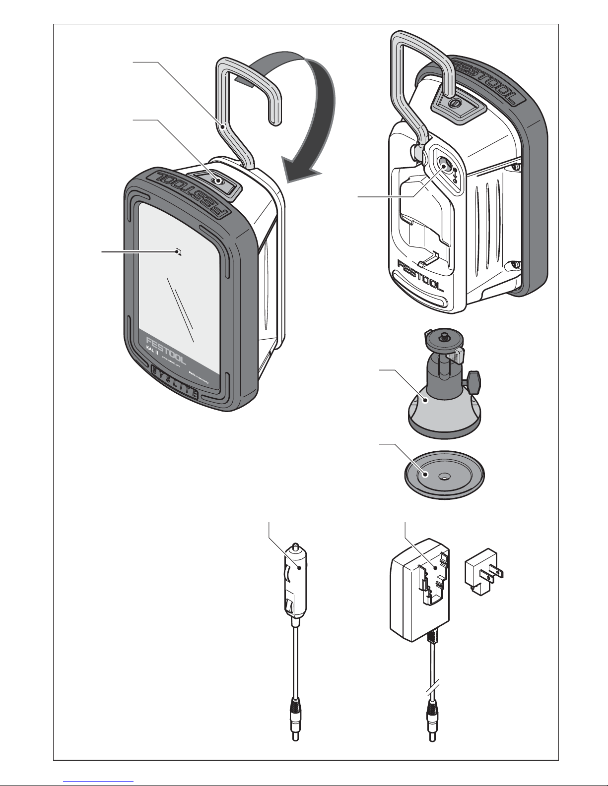
1-2
1-3
1-1
1
1-4
1-5
1-6
1-8 1-7
Page 3
3
Contents
1Symbols
2Safety instructions
WARNING!
Read all safety
warnings, instructions, illustrations
and specifications provided with this
tool.
Failure to follow all instructions
listed below may result in electric shock,
fire and/or serious injury.
Save all warnings and instructions for
future reference.
–
Handle the working light with care.
The working light may generate heat
that increases the risk of fire and explosions.
1 Symbols ................................. 3
2 Safety instructions................. 3
3 Intended use.......................... 4
4 Technical data........................ 5
5 Functional description........... 5
6 Operation ............................... 5
7 Service and maintenance ...... 10
8 Environment .......................... 10
9 Transport ............................... 11
10 Accessories............................ 11
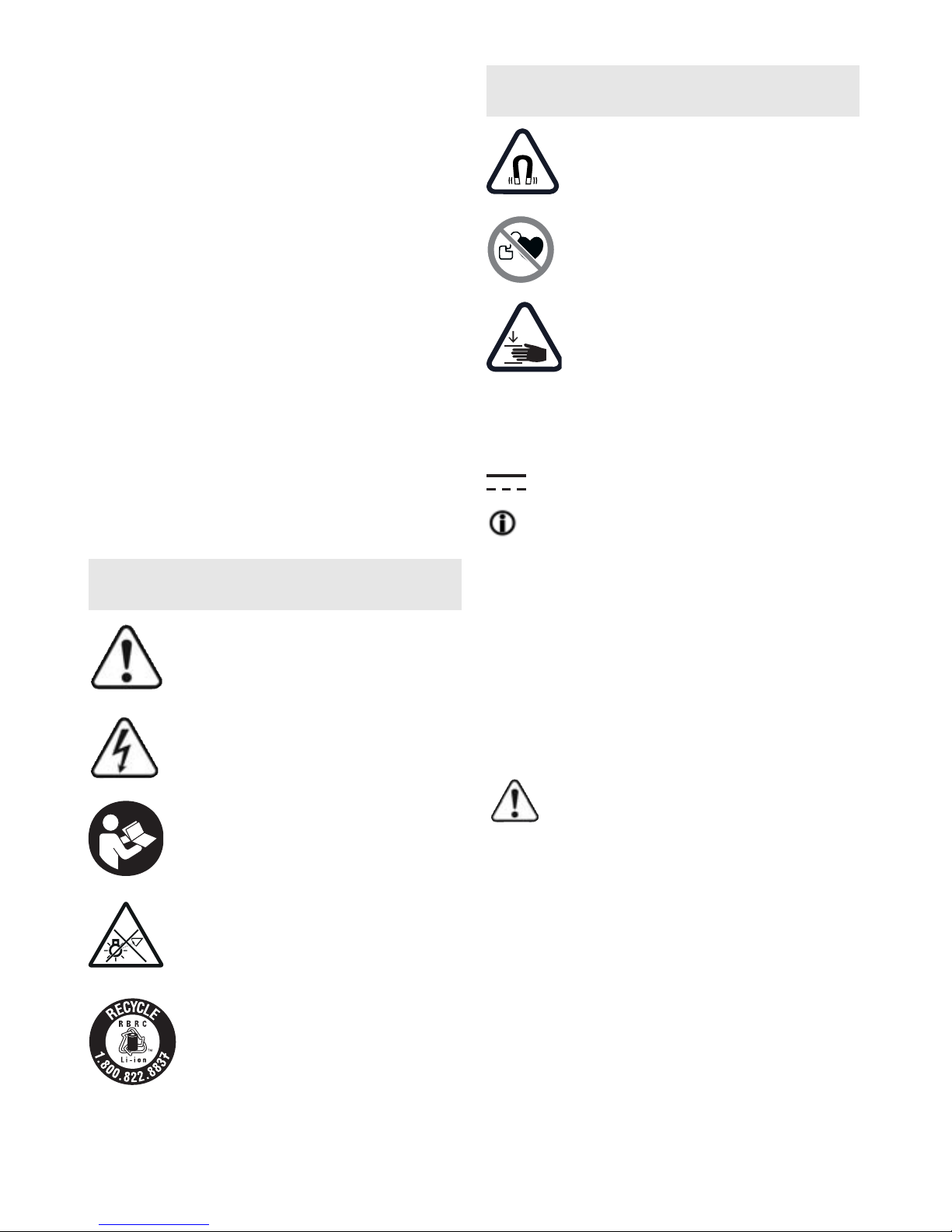
Symbol Significance
Warning of general danger
Risk of electric shock
Read operating instructions
and safety notices!
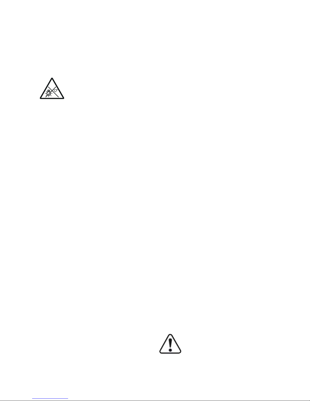
CAUTION!
Do not look directly
into the light beam!
RBRC Seal - LiIon
Warning against magnetic
field!
Prohibited for people with
pacemaker
Risk of pinching fingers and
hands!
Vvolts
W watts
d.c. direct current
hint, tipp
°C degree centigrade
Ah amps hour
kg kilograms
hhours
min minutes
Symbol Significance
Page 4
4
–
Never use the working light in potentially explosive environments.
–
Do not cover the working light when
switched on.
The working light heats
up during operation and can burn the
surface of the skin.
–
Warning against harmful
light radiation. Do not look
into the light beam for
long periods. Do not direct
the light beam towards other people
or animals.
Optical radiation can
damage the eyes.
–
Do not use the working light for road
lighting applications.
The working
light is not approved for illuminating
the road.
–
Always use compatible Festool battery packs in the working light.
Using other battery packs poses a fire
hazard and may cause personal injury.
–
Have your device repaired by qualified specialist staff and always use
original spare parts
to ensure that
your device operates reliably. The
light source contained in this luminaire shall only be replaced by the
manufacturer or his service agent or
a similar qualified person.
–
Always use original Festool parts
for repair and maintenance.
The use
of incompatible accessories or spare
parts can result in electric shocks or
other injuries.
–
When charging the working light, do
not use charging adapters from oth-
er manufacturers.
Otherwise, there
is a danger of fire and explosion.
– This device can be used by persons
with reduced physical, sensory or
mental abilities or those who lack experience or knowledge, if they are
supervised or have been instructed
on safe use of the device and understand the resulting dangers.
Chil-
dren
should always be supervised to
ensure that they do not play with the
machine.
–
Ensure stable footing or secure
mounting when securing to a tripod
or with a magnetic foot.
In the event
of unstable footing or insecure
mounting, the working light may fall
and cause personal injuries or material damage.
–
Protect the battery pack from excessive heat or constant heat sources
such as sunlight or naked flames.
There is a risk of explosion.
–
Never use water to extinguish burning li-ion battery packs, always use
sand
or a fire blanket.
CAUTION
Use only with Festool batteries
BPC12, 15 or 18.
FOR DRY LOCATION ONLY
3 Intended use
The compact working light was specifically designed for illuminating dry areas
in interior spaces.
The user is liable for improper
or non-intended use.
Page 5

5
4Technical data
5 Functional description
The pictures for the functional description are on a fold-out page at the beginning of the instruction manual. While
reading the manual you can fold out the
page for comparison and quick reference.
* not on all versions included in the
scope of delivery
6Operation
6.1 Charging the integral battery
pack
Prior to initial operation:
charge
battery pack for approx. 4 h!
Compact working light KAL II
Rated voltage / capacity of integral battery (LiIon) 7,2 V = / 2,9 Ah
Rated voltage with external Festool battery pack 10,8 - 18V =
Charging socket voltage range 7,2 - 18 V =
Lighting device 12x 1.5W Power LED
Light duration (internal bat-
tery)
Min. light: Stage 1 (30%) 5 h 30 min.
Max. light: Stage 2 (100%) 2 h 10 min.
Luminous flux, brightness Min. light: Stage 1 (30%) 310 Lumen
Max. light: Stage 2 (100%) 769 Lumen
Charge time of internal battery 90% / 100% 2 h 40 min / 3 h 20 min.
Permitted operating temperature range -5 °C to +55 °C
Permitted battery temperature for charging 0 °C to +45 °C
Weight (without external battery pack) 0,7 kg
Protection type IP 2X
- +
[1-1]
Charging state indicator LED
[1-2]
On/off switch with 3 settings
[1-3]
Folding attachment handle
[1-4]
Connecting socket for charging
adapter
[1-5]
Magnetic foot with spherical head*
[1-6]
Adapter plate*
[1-7]
Mains charging adapter*
[1-8]
Vehicle charging adapter
Page 6
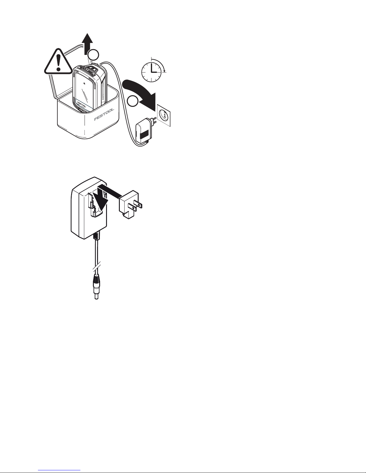
6
Insert the mains or vehicle charging
adapter into the connecting socket
[1-
4]
.
When the light is switched off, the
charging state indicator LED
[1-1]
displays the operating state of the internal
battery for the duration of the charging
process:
LED green - flashing quickly
Charging internal battery at maximum
rate.
LED green - flashing slowly
80% of internal battery capacity exceeded.
LED green - continuous light
Internal battery is charged to 90% and
then charged fully at reduced power.
LED red - flashing
General fault indication, e.g. incomplete
contact, short circuit, battery faulty.
LED red - continuous light
Battery temperature is outside the permitted range.
LED orange
Power failure mode, see
chapter 6.5
.
6.2 On/Off switch [1-2]
The ON/OFF switch
[1-2]
has three set-
tings:
– Press once -> Switch on in lighting
mode in energy-saving stage (Stage
1: 30%)
– Press twice -> Switch to max. lumi-
nosity (Stage 2: 100%)
– Press three times -> switch off
6.3 Voltage monitoring
If the minimum operating voltage is not
met during lighting mode with either internal or external battery pack, the device shifts to emergency mode. It reduces luminosity and switches off after 2
minutes.
4 h
2
1
Assembling mains charging adapter
2
Page 7
7
6.4 Temperature monitoring
If the device temperature does not remain within the specified limits, the
working light switches to emergency
mode. It reduces luminosity and then
switches off after 2 minutes.
6.5 Power failure mode
The working light has a power failure
mode. It automatically lights up the work
area in the event of a sudden power failure.
Hold down the ON/OFF switch
[1-2]
and insert the mains charging adapter
or car charging adapter in the connector socket
[1-4]
.
The working light turns off and the
charging indicator switches to flashing
orange (charging) or continuous orange
(fully charged). depending on the operating state.
In the event of an interruption to the external voltage supply, the working light
automatically switches on.
Switching off the mode:
Press the ON/OFF switch
[1-2]
again.
Charging indicator switches to standard
mode, see
chapter 6.1
.
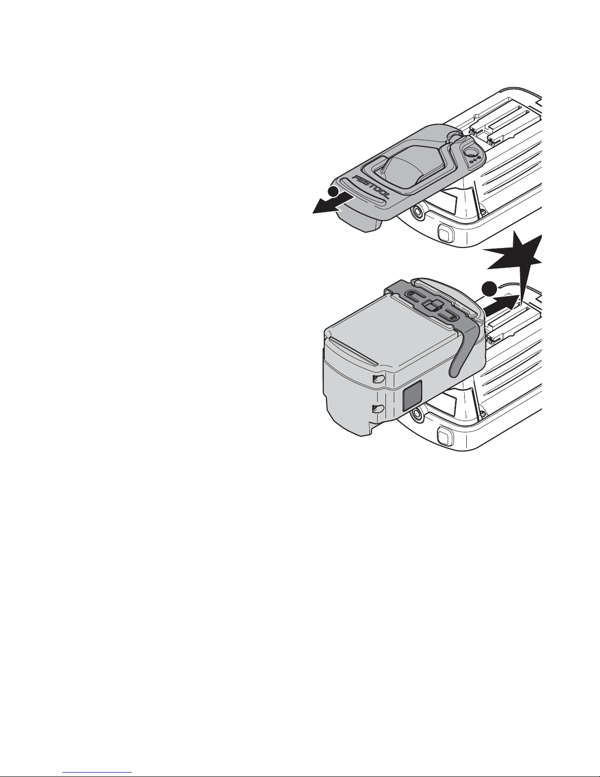
6.6 Operating with external Festool
battery pack [3A] + [3B]
The working light can operate with any
Festool battery pack from the BPC or
BPS series. When connected to the external Festool battery pack, the working
light only consumes power from this battery pack.
Inserting battery pack
1
2
3A
click
Page 8

8
Only compatible Festool chargers
can charge the Festool battery
pack.
6.7 Setup options
Attachment handle [1-3]
The folding attachment handle allows
you to hang the device from scaffolding
or similar structures.
If you decide to power the device
with an external Festool battery
pack, the attachment handle must
be detached beforehand
[4]
.
Setup angle
The working light can be set up in three
different angles
[5]
.
Removing battery pack
PRESS
2
1
3B
4
Position 1
5
15°
Position 2
30°
Page 9
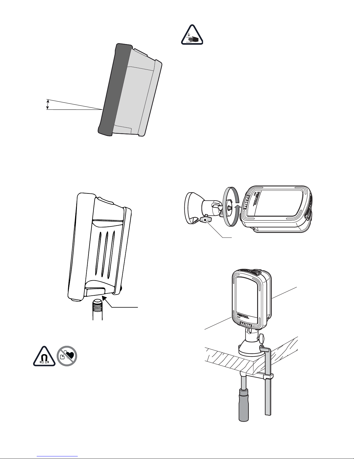
9
Tripod
A standard photographic tripod with UNC
1/4"-20 thread can be attached to the
threaded tripod socket
[6-1]
.
Magnetic foot with spherical head (part
accessories) [7]
Strong magnetic fields
may damage or destroy
electronic or mechanical
elements and devices The same also applies to
cardiac pacemakers
. The required safety distances can be found in
the manuals of these devices.
Risk of pinching fingers and
hands at the magnet!
Check the area at the magnetic foot
before use and clean if necessary.
Only use the magnetic foot for securing
the Festool working light using one of the
options described below:
Screw on magnetic foot at the tripod
socket
[6-1]
. This can be rotated in all directions by loosening the clamping
screw
[7-1]
.
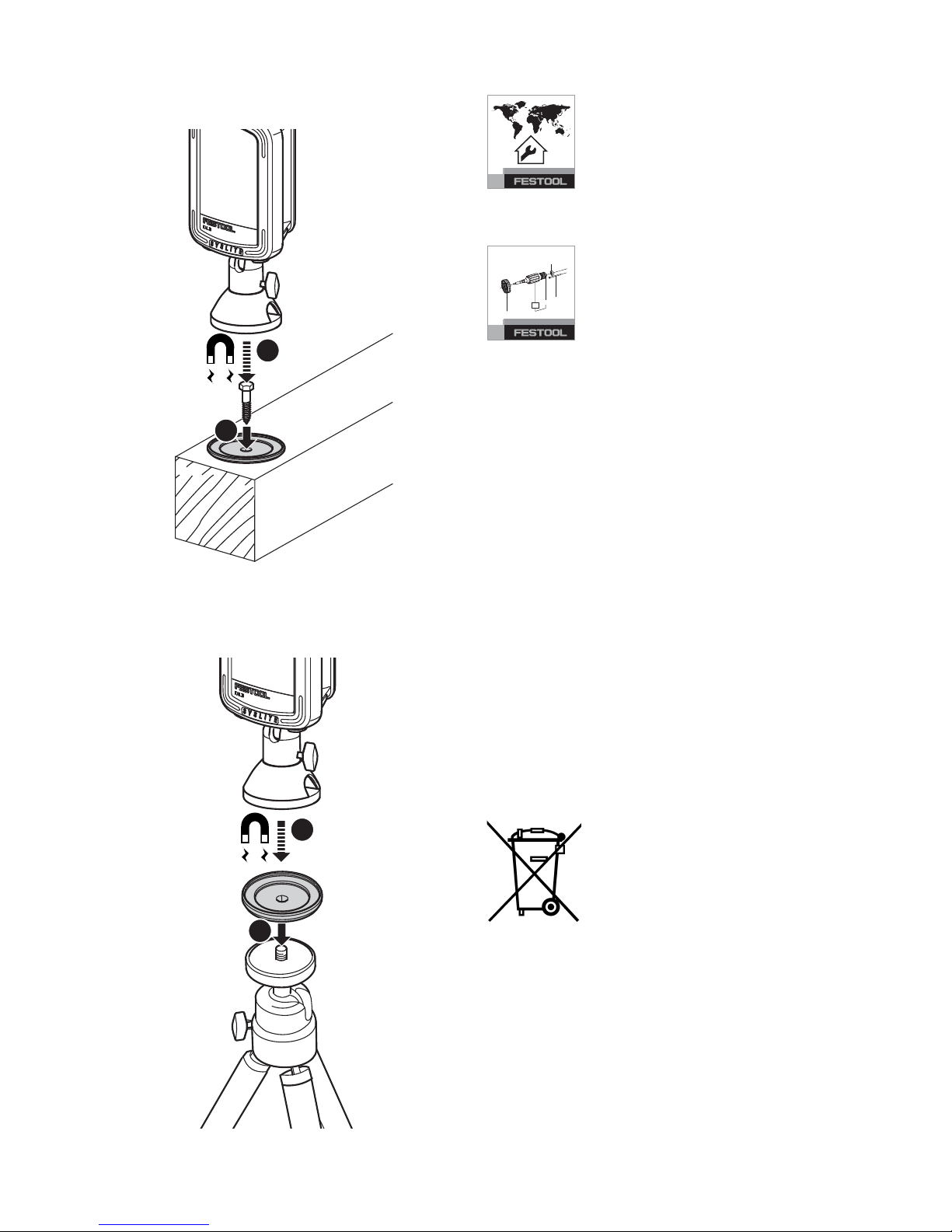
Secure the magnetic foot using one of
three options:
Secure with a clamp
Position 3
10°
6
6-1
7
7-1
Page 10
10
Magnetic mounting at the screwed-on
adapter plate
Magnetic mounting at the adapter plate
screwed on to a stand thread
7 Service and maintenance
Customer service and repair
only through manufacturer or service workshops:
Please find the nearest ad-
dress at: www.festoolusa.com/service
Use only original Festool
spare parts! Order No. at:
www.festoolusa.com/service
– Always clean the plastic cover on the
working light using a soft, dry cloth to
prevent any damage. Do not use solvents.
– Keep the contacts on the working
light and battery pack clean.
– Always appoint an authorised service
workshop to replace damaged integral batteries.
– All maintenance and repair work
which requires the housing to be
opened, must only be carried out by
an authorised service workshop.
8 Environment
Prior to disposal
Remove the integral battery from the device
! Dismantle the housing components and remove the battery. Dispose of the battery
using our return service.
1
2
1
2
EKAT
1
2
3
5
4
Page 11

11
Battery Disposal
The RBRCTM Seal
The RBRCTM (Rechargeable Battery
Recycling Corporation) Seal on nickel cadmium (NiCd),
nickel metal hydride (NiMH) or lithiumion (LiIon) batteries (or battery packs) indicates Festool is voluntarily participating in an industry program to collect and
recycle these batteries at the end of their
useful life, when taken out of service in
the United States or Canada. In some areas, it is illegal to place spent batteries in
the trash or municipal solid waste
stream and RBRC Program provides an
environmentally conscious alternative.
Please call 1-800-822-8837 for information on battery recycling and disposal
bans/restrictions in your area, or return
your batteries to the Festool Service
Center for recycling. Help protect our
environment and conserve natural resources!
9Transport
The lithium-ion batteries are subject to
the requirements of the legislation on
hazardous goods. A li-ion battery pack
alone falls below the applicable limit value and certified as per UN manual ST/
SG/ AC.10/11/rev. 3 part III, subsection
38.3. However, dangerous goods regulations may apply when several battery
packs are transported For shipping by
third parties (e.g. air transport or freight
forwarding company) special requirements with regard to packaging and labelling must be observed. For the preparation of the package an expert on hazardous goods must be consulted. Please
observe any further national regulations.
10 Accessories
Use only original Festool accessories
and Festool consumable material intended for this machine. These components are designed specifically for this
machine. Using accessories and consumable material from other suppliers
will most likely affect the quality of your
results and limit warranty claims. Machine wear or your own personal workload may increase depending on the application. Protect yourself and your machine, and preserve your warranty
claims by always using original Festool
accessories and Festool consumable
material!
The order numbers of the accessories
and tools can be found in the Festool catalogue or on the Internet under
"www.festoolusa.com".
WARNING
Risk of fire or injury
Do not attempt to disassemble the
battery or remove any component
projecting from the battery terminals.
Prior to disposal, protect exposed
terminals with heavy insulating
tape to prevent shorting.
Page 12

12
Sommaire
1Symboles
2 Consignes de sécurité
Avertissement !
Veuillez lire
toutes les consignes de sécurité et instructions.
Le non-respect des consignes
d'avertissement et des instructions peut
occasionner un choc électrique, un incendie et/ou des blessures graves.
Conserver toutes les consignes de sécurité et notices d'instructions pour une
référence future.
–
Utilisez le projecteur de travail avec
précaution.
Le projecteur de travail
peut générer de la chaleur, d'où un
1 Symboles ............................... 12
2 Consignes de sécurité........... 12
3 Utilisation en conformité avec
les instructions...................... 14
4 Caractéristiques techniques . 14
5 Description fonctionnelle ...... 15
6 Mise en service...................... 15
7 Entretien et maintenance...... 20
8 Environnement ...................... 20
9 Transport ............................... 21
10 Accessoires............................ 21
Symbole Signification
Avertissement de danger
Avertissement contre le
risque d'électrocution
Notice d'utilisation, lire les
consignes de sécurité !
ATTENTION !
Ne regardez
jamais dans l'axe du faisceau
lumineux !
RBRC Sceau - LiIon
Attention au champ magnétique !
Interdit aux personnes dotées
d'un stimulateur cardiaque
Danger d'écrasement des
doigts et des mains !
VVolt
WWatt
d.c. Courant continu
Information, astuce
°C Centigrade
Ah Heure d’ampère
kg kilogramme
hheure
min minute
Symbole Signification
Page 13

13
risque accru d'incendie et d'explosion.
–
Ne travaillez pas avec le projecteur
de travail dans un environnement
présentant un risque d'explosion.
–
Ne couvrez pas le projecteur pendant son fonctionnement.
La température du projecteur de travail
augmente pendant son utilisation et
la chaleur accumulée peut provoquer
des brûlures.
–
Avertissement sur les
rayonnements lumineux
nocifs. Ne regardez pas
longtemps dans l'axe du
faisceau lumineux. Ne dirigez pas le
faisceau lumineux sur d'autres personnes ou animaux.
Le rayonnement
optique peut être dommageable pour
les yeux.
–
N'utilisez pas le projecteur de travail pour la conduite sur route.
Il
n'est pas homologué pour l'éclairage
de la chaussée.
–
Utilisez uniquement les batteries
Festool prévues pour le projecteur
de travail.
L'utilisation d'autres batteries peut entraîner des blessures
et un risque d'incendie.
–
Faites réparer votre outil uniquement par un personnel qualifié ; les
réparations doivent être effectuées
avec des pièces d'origine uniquement,
afin de garantir la fiabilité de
l'appareil. La source lumineuse
contenue dans cet appareil doit uniquement être remplacée par le fabricant ou un atelier du Service Après-
Vente afin de garantir la fiabilité de
l'appareil.
–
Pour la réparation et l'entretien,
n'utilisez que des pièces Festool
d'origine.
L'utilisation d'accessoires
ou de pièces de rechange non adaptés risque de provoquer une électrocution ou des blessures.
–
Ne chargez pas le projecteur de travail avec un adaptateur réseau d'un
autre fabricant.
Dans le cas
contraire, il existe un risque d'incendie et d'explosion.
– Cet appareil peut être utilisé par des
personnes ayant des capacités physiques, sensorielles ou mentales limitées ou manquant d'expérience et
de connaissance, lorsqu'elles sont
sous surveillance ou bien qu'elles
ont reçu une formation sur l'utilisation sûre de l'appareil et en comprennent les dangers qui en
résultent.
Les enfants
devraient rester sous surveillance afin de s'assurer qu'ils ne jouent pas avec
l'appareil.
–
Lors de la mise en place sur un trépied ou sur un socle magnétique,
vérifiez que le projecteur est stable
et bien fixé.
En cas d'instabilité ou de
fixation inappropriée, le projecteur
peut tomber et provoquer des blessures ou des dommages matériels.
–
Protégez la batterie contre la chaleur, p. ex. également contre les
rayons de soleil permanents ou le
feu.
Il y a risque d'explosion.
–
N'utilisez en aucun cas de l'eau pour
Page 14

14
éteindre une batterie "Li-ion" enflammée
, utilisez du
sable
ou une
couverture anti-feu.
ATTENTION
Utilisez seulement avec les
batteries FESTOOL BPC 12, 15 ou 18.
CONVIENT AUX EMPLACEMENTS SEC
3 Utilisation en conformité
avec les instructions
Le projecteur de travail compact est prévu pour l'éclairage conforme de zones
sèches en intérieur.
L'utilisateur est responsable
des dommages provoqués par
une utilisation non conforme.
4 Caractéristiques techniques
Projecteur de travail compact KAL II
Tension nominale / capacité de la batterie interne (Li-ion) 7,2 V = / 2,9 Ah
Tension nominale avec batterie externe Festool 10,8 - 18V =
Plage de tension prise de
charge
7,2 - 18 V =
Ampoule 12 LED 1,5 W Power
Durée d'éclairage (batterie
interne)
Éclairage min. : niveau 1
(30 %)
5 h 30 min.
Éclairage max. : niveau 2
(100 %)
2 h 10 min.
Flux lumineux, luminosité Éclairage min. : niveau 1
(30 %)
310 Lumen
Éclairage max. : niveau 2
(100 %)
769 Lumen
Temps de charge de la batterie interne à 90 % / 100 % 2 h 40 min / 3 h 20 min.
Plage de température de fonctionnement admissible de -5 °C à +55 °C
Température admissible de la batterie pour la charge de 0 °C à +45 °C
Poids (sans batterie externe) 0,7 kg
Degré de protection IP 2X
- +
Page 15

15
5 Description fonctionnelle
Des eléments fournis sont disponibles
sur le volet qui se trouve au début de
cette notice d'utilisation. Vous pouvez
ainsi déplier cette page et visualiser en
permanence les différentes parties de
l'outil lorsque vous lisez la notice.
* non inclus dans la livraison standard de
toutes les variantes
6 Mise en service
6.1 Charge de la batterie interne
Avant la première mise en service:
charger le bloc batteries env. 4 h !
Branchez l'adaptateur de charge réseau ou allume-cigare dans la prise de
raccordement
[1-4]
.
En mode désactivé, la DEL d'affichage de
charge
[1-1]
indique l'état de fonctionnement de la batterie interne pendant la
mise en charge :
LED verte - clignotement rapide
La batterie interne a atteint son niveau
de charge maximal.
LED verte - clignotement lent
La batterie interne est chargée à 80 %.
[1-1]
LED d'affichage de charge
[1-2]
Interrupteur marche/arrêt avec 3
niveaux
[1-3]
Poignée de fixation rabattable
[1-4]
Prise de raccordement pour adaptateur de charge
[1-5]
Socle magnétique avec tête arrondie*
[1-6]
Plaque adaptatrice*
[1-7]
Adaptateur de charge réseau*
[1-8]
Adaptateur de charge pour allumecigare
4 h
2
1
Montage du adaptateur de charge
2
Page 16

16
LED verte - allumée en continu
La batterie interne est chargée à 90 % et
le processus de charge complète se
poursuit avec un courant réduit.
LED rouge - clignotement
Affichage de défaut général, par ex. pas
de contact total, court-circuit, batterie
défectueuse, etc.
LED rouge - allumée en continu
La température de la batterie est en-dehors des valeurs limites admissibles.
LED orange
Mode coupure de courant, voir le
cha-
pitre 6.5
.
6.2 Marche/arrêt [1-2]
L'interrupteur marche/arrêt
[1-2]
a trois
niveaux :
– 1 pression -> activation de l'éclairage
en mode économie d'énergie (niveau
1: 30%)
– 2 pressions -> commutation sur
l'éclairage maximal (niveau 2 :
100 %)
– 3 pressions -> désactivation
6.3 Surveillance de la tension
Lorsque la tension de fonctionnement
minimale n'est pas atteinte pendant
l'éclairage avec la batterie interne ou externe, le projecteur de travail passe en
mode de secours, avec une luminosité
réduite, et s'éteint au bout de 2 minutes.
6.4 Surveillance de la température
Si la plage de température admissible
n'est pas atteinte ou est dépassée, le
projecteur de travail passe en mode de
secours, avec une luminosité réduite, et
s'éteint après 2 minutes.
6.5 Mode coupure de courant
Le projecteur de travail dispose d'un
mode coupure de courant. Ainsi, en cas
de brusque coupure de courant, il peut
assurer l'éclairage de l'espace de travail.
Pour ce faire, maintenez l'interrupteur
marche/arrêt
[1-2]
enfoncé et branchez l'adaptateur de charge pour allume-cigare ou réseau dans la prise
[1-4]
.
Le projecteur de travail s'éteint et, selon
l'état de charge, la LED orange clignote
(processus de charge en cours) ou est allumée en continu (processus de charge
terminé).
En cas d'interruption de la source d'alimentation externe, le projecteur de travail
s'allume désormais automatiquement.
Pour désactiver le mode :
Appuyez de nouveau sur l'interrupteur
marche/arrêt
[1-2]
.
L'affichage de charge passe en mode
standard, voir le
chapitre 6.1
.
Page 17

17
6.6 Utilisation avec batterie externe
Festool [3A] + [3B]
Le projecteur de travail peut être utilisé
avec toute batterie Festool des séries
BPC et BPS. Relié à la batterie, le projecteur de travail puise uniquement dans la
capacité de la batterie Festool externe.
La batterie Festool peut être chargée uniquement avec un chargeur
Festool correspondant.
6.7 Positionnements possibles
Poignée de fixation [1-3]
La poignée de fixation rabattable permet
d'accrocher l'appareil à un échafaudage,
par exemple.
La poignée de fixation doit être retirée pour une utilisation avec une
batterie Festool externe
[4]
.
Insérer la batterie
1
2
3A
Retirer la batteria
APPUYEZ
2
1
3B
4
Page 18

18
Angle
Le projecteur de travail peut être pivoté
sur trois angles différents
[5]
.
Trépied
Un filetage standard de trépied d'appareil photo UNC 1/4"-20 peut être vissé à
la prise de filetage de trépied
[6-1]
.
Socle magnétique avec tête arrondie
(accessoire partiel) [7]
Des champs magnétiques puissants
peuvent
déranger ou
détruire
les
éléments et appareils électroniques ou
mécaniques. Ceci est aussi valable pour
les
stimulateurs cardiaques
. Les distances de sécurité obligatoires peuvent
être consultées dans les manuels de cet
appareil.
Danger d'écrasement des doigts
et des mains sur l'aimant !
Avant utilisation, vérifier la surface
du socle magnétique et la nettoyer
le cas échéant.
N'utiliser le socle magnétique que pour
fixer l'éclairage de travail Festool selon
les possibilités décrites ci-dessous :
Visser le socle magnétique sur la douille
du filetage de fixation
[6-1]
. Le socle
peut pivoter dans toutes les directions en
desserrant la vis de serrage
[7-1]
.
Position 1
5
15°
Position 2
30°
Position 3
10°
6
6-1
Page 19

19
Fixez ensuite le socle magnétique selon
l'une des trois méthodes suivantes :
Fixation sur un serre-joint
Fixation magnétique sur la plaque
adaptatrice vissée
Fixation magnétique sur la plaque
adaptatrice vissée sur un filetage de
trépied
7
7-1
1
2
1
2
Page 20

20
7 Entretien et maintenance
Seuls le fabricant et un atelier
homologué sont habilités à effectuer
toute réparation ou
service
. Les adresses à proximité sont
disponibles sur: www.festoolusa.com/
service
Utilisez uniquement des pièces
de rechange Festool d‘origine.
Référence sur: www.festoolu-
sa.com/service
– Nettoyez le disque plastique du pro-
jecteur de travail avec un chiffon
doux et sec afin de ne pas l'endommager. N'utilisez pas de solvant.
– Maintenez bien propres les contacts
de raccordements du projecteur de
travail et de la batterie.
– Une batterie interne endommagée
doit être remplacée dans un atelier
après-vente autorisé.
– Toute opération de réparation ou
d'entretien nécessitant l'ouverture
du carter ne peut être entreprise que
par un atelier de service après-vente
agréé.
8 Environnement
Avant l'élimination
Retirez la batterie interne
de l'outil
! Pour cela, dévissez les pièces du carter et
retirez la batterie. Envoyez
la batterie à notre système
de reprise.
Mise au rebut des batteries
Le sceau RBRC
TM
Le sceau RBRC
TM
(Rechargeable Bat-
tery Recycling Corporation), que se trouve sur les batteries
au nickel-cadmium (NiCd), nickel-hydrure métallique (NiMH) ou au lithiumion (LiIon) indique que Festool participe
volontairement à une programme industriel de ramassage et de recyclage de
ces batteries au terme de leur vie utile,
pourvu qu’elles soient mise hors service
aux Ètats-Unis ou au Canada. Dans certaines régions, il est illégal placer de
batteries usées à la poubelle ou au ramassage d’ordures municipal, et RBRC
programme offre une alternative respectueuse de l’environnement.
S'il vous plaît appeler 1-800-822-8837
pour obtenir des renseignements sur les
interdictions de recyclage des batteries
et l’élimination/restrictions dans votre
région ou renvoyez vos batteries à un
EKAT
1
2
3
5
4
AVERTISSEMENT
Risque d’incendie ou de blessures
Ne tentez pas de désassembler la
batterie ou d’enlever tout composant faisant saillie des bornes de
batterie.
Avant la mise au rebut, protégez les
bornes exposées à l’aide d’un ruban
isolant épais pour prévenir le courtcircuitage.
Page 21

21
Centre de Service Festool pour recyclage. Aidez à protéger notre environnement et préserver les ressources naturelles!
9Transport
Les batteries Li-ion comprises sont soumises aux exigences du droit sur les matières dangereuses. La quantité équivalente de lithium contenue dans la batterie Li-ion se situe sous les valeurs
limites applicables et est contrôlée
d'après le manuel UN ST/SG/AC.10/11/
Rev.3 partie III, sous-paragraphe 38.3.
Pour cette raison, la batterie Li-ion n'est
soumise, ni en tant que composant individuel, ni insérée dans un appareil, aux
prescriptions nationales et internationales concernant les matières dangereuses. Les prescriptions concernant les
matières dangereuses peuvent toutefois
être applicables en cas de transport de
plusieurs batteries. Dans ce cas il peut
s'avérer nécessaire de respecter des
conditions particulières. Pour l'envoi par
des tiers (par ex. transport aérien ou entreprise de transport), tenez compte des
exigences spéciales pour l'emballage et
le marquage. Pour la préparation d'un
colis, prenez conseil auprès d'un expert
pour matières dangereuses. Respectez
les autres prescriptions nationales en vigueur.
10 Accessoires
Utilisez uniquement les accessoires Festool et consommables Festool d'origine
prévus pour cette machine, car ces composants systèmes sont parfaitement
adaptés les uns par rapport aux autres.
Si vous utilisez des accessoires et
consommables d'autres marques, la
qualité du résultat peut être dégradée et
les recours en garantie peuvent être
soumis à des restrictions. L'usure de la
machine ou votre charge personnelle
peuvent augmenter selon chaque application. Pour cette raison, protégez-vous,
votre machine et vos droits à la garantie
en utilisant exclusivement des
accessoires Festool et des
consommables Festool d'origine !
Les références des accessoires et des
outils figurent dans le catalogue Festool
ou sur Internet sous "www.festoolusa.com".
Page 22

22
Índice
1Símbolos
2 Indicaciones de seguridad
Advertencia:
Lea todas las indi-
caciones de seguridad e instrucciones.
Si no se cumplen debidamente las indicaciones de advertencia y las instrucciones, puede producirse una descarga
eléctrica, quemaduras o lesiones graves.
Guarde todas las indicaciones de seguridad e instrucciones para que sirvan de
futura referencia.
–
Maneje la lámpara de trabajo con
precaución.
La lámpara de trabajo
1 Símbolos................................ 22
2 Indicaciones de seguridad..... 22
3 Uso conforme a lo previsto.... 24
4 Datos técnicos ....................... 24
5 Descripción de las funciónes 24
6 Puesta en servicio ................. 25
7 Mantenimiento y cuidado ...... 29
8 Medio ambiente ..................... 29
9 Transporte ............................. 30
10 Accesorios ............................. 30
Símbolo Significado
Aviso de peligro general
Peligro de electrocución
¡Leer el manual de instrucciones y las indicaciones de
seguridad!
¡ATENCIÓN!
¡No mire al haz
de luz directamente!
RBRC Sello - LiIon
Advertencia de un campo
magnético.
Prohibido para personas con
marcapasos
¡Peligro de aplastamiento de
dedos y manos!
V
voltios
Wvatio
d.c.
tensión continua
Indicación, consejo
°C
centigrados
Ah
amperio-hora
kg kilogramo
hhora
min minuto
Símbolo Significado
Page 23

23
puede generar calor e incrementar el
riesgo de incendio o explosión.
–
No trabaje con la lámpara en entornos potencialmente explosivos.
–
No cubra la lámpara de trabajo
mientras esté funcionando.
La lámpara se calienta durante su funcionamiento y puede provocar
quemaduras si se acumula el calor.
–
Peligro de daños por radiación luminosa. No mire
al haz de luz durante mucho tiempo. No dirija nun-
ca el haz de luz hacia otras personas
o hacia animales.
La radiación óptica
puede provocar daños en los ojos.
–
No utilice la lámpara de trabajo en
la circulación vial.
La lámpara no
está homologada para su uso en la
circulación vial.
–
Utilice únicamente las baterías de
Festool previstas para la lámpara de
trabajo.
El uso de otras baterías puede provocar lesiones y riesgo de incendio.
–
Haga reparar su herramienta únicamente por personal técnico cualificado y solo con piezas de recambio
originales.
De esta forma queda garantizada la seguridad de la herramienta. La sustitución de la fuente de
luz instalada en esta herramienta
debe encargarse únicamente al fabricante o a un taller de servicio técnico autorizado.
–
Utilice exclusivamente piezas originales de Festool para la reparación
y el mantenimiento de su herra-
mienta.
El uso de accesorios o piezas
de recambio no previstos puede producir descargas eléctricas o lesiones.
–
No cargue la lámpara de trabajo con
adaptadores de carga para la red de
otros fabricantes.
De lo contrario,
existe peligro de incendio y explosión.
– Esta máquina puede ser utilizada por
personas con las capacidades físicas, sensoriales o mentales disminuidas o con falta de experiencia y
conocimientos si son vigiladas o han
sido instruidas respecto al uso seguro de la máquina y comprenden los
peligros derivados de la misma. Los
niños
no deben dejarse desatendidos
con el fin de evitar que jueguen con la
máquina.
–
En caso de fijarse a un trípode o con
un pie magnético, asegúrese de que
la posición es estable y de que la fijación es segura.
Si la posición no es
estable o la fijación es insegura, la
lámpara de trabajo puede caer y provocar lesiones o daños materiales.
–
No exponer la batería a fuentes de
calor, como por ejemplo, la radiación solar prolongada o el fuego.
Existe peligro de explosión.
–
No utilizar agua para apagar una batería Li-Ion en llamas, utilizar siempre arena
o una manta contra
incendios.
PRECAUCIÓN
Utilice solamente con las
baterías FESTOOL BPC 12, 15 o 18.
PARA UBICACIÓN EN SECO SOLAMENTE
Page 24

24
3 Uso conforme a lo previsto
La compacta lámpara de trabajo está
prevista para iluminar zonas secas en
espacios interiores.
El usuario será responsable
de cualquier utilización indebida.
4 Datos técnicos
5 Descripción de las funció-
nes
Las imágenes con la dotación de suministro se encuentran en una hoja desplegable al comienzo de este manual de
instrucciones. Cuando lea este manual,
le recomendamos que despliegue esta
página para disponer fácilmente de una
vista general de la máquina.
Lámpara de trabajo compacta KAL II
Tensión nominal / capacidad de la batería interna (Li-Ion) 7,2 V = / 2,9 Ah
Tensión nominal con la batería externa de Festool 10,8 - 18 V =
Margen de tensión de la toma
de carga
7,2 - 18 V =
Medio luminoso 12 LED Power de 1,5 W
Duración de la iluminación
(batería interna)
Luz mín.: nivel 1 (30 %) 5 h 30 min.
Luz máx.: nivel 2 (100 %) 2 h 10 min
Flujo luminoso, luminosidad Luz mín.: nivel 1 (30 %) 310 lúmenes
Luz máx.: nivel 2 (100 %) 769 lúmenes
Tiempo de recarga de la batería interna 90 %/100 % 2 h 40 min / 3 h 20 min
Margen de temperaturas de funcionamiento permitido -5 °C a +55 °C
Temperatura de la batería permitida para recarga 0 °C a +45 °C
Peso (sin batería externa) 0,7 kg
Clase de protección IP 2X
- +
[1-1]
LED indicador de carga
[1-2]
Interruptor de conexión y desconexión con 3 niveles
[1-3]
Estribo de sujeción deslizable
[1-4]
Base de conexión para adaptador
de carga
[1-5]
Pie magnético con cabeza esférica*
[1-6]
Placa adaptadora*
[1-7]
Adaptador de carga para la red*
Page 25

25
* no para todas las variantes de la dotación de suministro
6 Puesta en servicio
6.1 Cargar la batería interna
Antes de la primera puesta en servicio:
cargar el acumulador duran-
te aprox. 4 h.
Enchufe el adaptador de carga para la
red o para el vehículo en la base de conexión
[1-4]
.
En estado desconectado, el LED indicador de carga
[1-1]
muestra el estado de
funcionamiento de la batería interna durante el proceso de carga:
LED verde: parpadeo rápido
La batería interna se carga con la corriente máxima.
LED verde: parpadeo lento
La batería interna está cargada al 80 %.
LED verde: luz fija
La batería interna está cargada al 90 % y
la carga se completa con la corriente reducida.
LED rojo: parpadeo
Indicador de error general, p. ej. no existe contacto, cortocircuito, batería defectuosa, etc.
LED rojo: luz fija
La temperatura de la batería está fuera
del valor límite permitido.
LED naranja
Modo de corte de corriente, véase el
ca-
pítulo 6.5
.
6.2 Interruptor de conexión y desco-
nexión [1-2]
El interruptor de conexión y desconexión
[1-2]
tiene tres niveles:
– Pulsar una vez -> conectar en el
modo de iluminación con nivel de
ahorro energético (nivel 1: 30 %)
– Pulsar dos veces -> cambiar a la lu-
minosidad máxima (nivel 2: 100 %)
– Pulsar tres veces -> desconectar
[1-8]
Adaptador de carga para el vehículo
4 h
2
1
Montaje del adaptator de carga
2
Page 26

26
6.3 Control de tensión
Si en el modo de iluminación no se alcanza la tensión de servicio mínima con
la batería interna o externa, la lámpara
de trabajo pasará al modo de emergencia con una luminosidad reducida y se
desconectará al cabo de 2 minutos.
6.4 Control de temperatura
Si el rango de temperaturas de funcionamiento permitido se supera o no se alcanza, la lámpara de trabajo pasará al
modo de emergencia con una luminosidad reducida y se desconectará a cabo
de 2 minutos.
6.5 Modo de corte de corriente
La lámpara de trabajo dispone de un
modo de corte de corriente. De esta forma, si se produce un corte de corriente
repentino, puede seguir iluminando el
área de trabajo.
Para ello, debe mantenerse pulsado el
interruptor de conexión y desconexión
[1-2]
y conectarse el adaptador de
carga para la red o para el vehículo en
la base de conexión
[1-4]
.
La lámpara de trabajo se apaga y el indicador de carga cambia, en función del
estado de funcionamiento, al parpadeo
de color naranja (cargar) o a la luz fija de
color naranja (cargado).
En caso de interrupción del suministro
de tensión externo, ahora la lámpara de
trabajo se conectará automáticamente.
Para desconectar el modo de corte de
corriente:
Vuelva a pulsar el interruptor de conexión y desconexión
[1-2]
.
El indicador de carga cambia al modo estándar, véase el
capítulo 6.1
.
6.6 Funcionamiento con la batería
externa de Festool [3A] + [3B]
La lámpara de trabajo se puede utilizar
con todas las baterías Festool de las series BPC y BPS. Una vez conectada a la
batería externa de Festool, la lámpara de
trabajo funciona solo con la capacidad de
dicha batería.
Insertar la batería
1
2
3A
Page 27

27
La batería de Festool debe cargarse exclusivamente con el correspondiente cargador de Festool.
6.7 Opciones de emplazamiento
Estribo de sujeción [1-3]
El estribo de sujeción deslizable permite
colgar la herramienta en andamios o
puntos similares.
Para el funcionamiento con una batería externa de Festool es necesario retirar el estribo de sujeción
[4]
.
Ángulo de emplazamiento
La lámpara de trabajo se puede emplazar en tres ángulos diferentes
[5]
.
Trípode
El casquillo con rosca del trípode [6-1]
admite una rosca UNC 1/4"-20 estándar
para trípode de fotografía.
Quitar la batería
PULSE
2
1
3B
4
Posición 1
5
15°
Posición 2
30°
Posición 3
10°
Page 28

28
Pie magnético con cabeza esférica (accesorio parcial) [7]
Los
campos magnéticos
potentes
pueden averiar
o
estropear
elementos
mecánicos y aparatos. Esto también rige
para
marcapasos
. Las distancias de seguridad necesarias se encuentran en los
manuales de estos aparatos.
Peligro de aplastamiento de dedos y manos en el imán.
Comprobar y, dado el caso, limpiar
la superficie del pie magnético antes de utilizarla.
Utilizar el pie magnético solamente para
la fijación de la luz de trabajo Festool en
las posibilidades descritas seguidamente:
Atornillar el pie magnético en el casquillo de la rosca del trípode
[6-1]
. Este pie
puede girar en todas direcciones aflojando el tornillo de apriete
[7-1]
.
A continuación, el pie magnético se puede fijar de una de estas tres maneras:
Fijación con una mordaza de rosca
6
6-1
7
7-1
Page 29

29
Fijación magnética a la placa adaptadora atornillada
Fijación magnética a la placa adaptadora atornillada a una rosca para trípode
7 Mantenimiento y cuidado
El
Servicio de atención al
cliente y reparaciones
solo
está disponible por parte del fabricante o de los talleres de reparación:
encuentre la dirección más próxima a
usted en: www.festoolusa.com/service
Utilice únicamente piezas de
recambio Festool originales.
Referencia en: www.festoolu-
sa.com/service
– Limpie el cristal de material sintético de
la lámpara de trabajo solo con un paño
suave y seco a fin de evitar cualquier
desperfecto. No utilice disolventes.
– Mantenga siempre limpios los con-
tactos de unión de la lámpara de trabajo y de la batería.
– La sustitución de la batería interna
cuando está averiada debe realizarla
únicamente un taller de servicio autorizado.
– Todos los trabajos de mantenimiento
y reparación que exijan abrir la carcasa tan sólo pueden ser llevados a
cabo por un taller autorizado.
8 Medio ambiente
Antes de su eliminación
Extraiga la batería interna
de la herramienta
. Para
ello, desatornille las piezas
de la carcasa y retire la batería. Entregue la batería a su
distribuidor para eliminarla
mediante nuestro sistema
de reciclaje.
1
2
1
2
EKAT
1
2
3
5
4
Page 30

30
Reciclaje de baterías
El Sello RBRC
TM
El Sello RBRC
TM
(Corporación de Re-
ciclaje de Baterías
Recargables) de níquel-cadmio (NiCd),
níquel-hidruro metálico (NiMH) o iones
de litio (LiIon) en baterías (o acumuladores) indica que Festool está participando
voluntariamente en un programa de la
industria para recoger y reciclar estas
baterías al final de su vida útil, cuando se
retiran de servicio en los Estados Unidos
y Canadá.En algunas zonas, es ilegal tirar las baterías en la basura o la corriente de residuos sólidos municipales y del
programa RBRC ofrece una alternativa
medioambiental conveniente.
Por favor, llame al 1-800-822-8837 para
obtener información sobre las prohibiciones/ restricciones sobre el reciclaje y
la eliminación de baterías en su lugar, o
devuelva las baterías al Centro de Servicio Festool para reciclarlas. Ayude a proteger nuestro medio ambiente y conservar los recursos naturales!
9Transporte
Los acumuladores de iones de litio incluidos están sujetos a las disposiciones
de la legislación sobre mercancías peligrosas. La capacidad de litio equivalente
en la batería Li-Ion se encuentra por debajo del valor límite correspondiente y ha
sido revisada conforme el Manual de
Pruebas y Criterios de NU ST/SG/AC.10/
11/Rev.3 parte III, subapartado 38.3. Así,
la batería Li-Ion está sujeta a la normativa nacional e internacional sobre mercancías peligrosas, no como pieza única
ni instalada en un aparato. La normativa
sobre mercancías peligrosas puede ser
relevante en el transporte de varias baterías. En este caso, puede ser necesario
respetar las condiciones especiales.
Para el transporte mediante servicios de
terceros (p. ej., transporte aéreo o empresa de transportes) es obligatorio
cumplir unos requisitos particulares en
cuanto a embalaje y señalización. Debe
consultarse a un experto en mercancías
peligrosas para la preparación del envío.
Ténganse en cuenta el resto de regulaciones nacionales.
10 Accesorios
Utilice únicamente los accesorios Festool originales y el material de consumo
Festool diseñados para esta máquina,
puesto que los componentes de este sistema están óptimamente adaptados entre sí. La utilización de accesorios y ma-
ADVERTENCIA
Riesgo de fuego o daños
No intente desarmar la batería ni
quitar ninguno de los componentes
que sobresalen de las terminales
de la batería.
Antes de tirarla, proteja las terminales que están al descubierto con
cinta adhesiva aislante gruesa para
prevenir cortocircuitos.
Page 31

31
terial de consumo de otros fabricantes
puede afectar a la calidad de los resultados de trabajo y conllevar una limitación
de los derechos de la garantía. El desgaste de la máquina o de su carga personal puede variar en función de la aplicación. Utilice únicamente accesorios ori-
ginales y material de consumo de
Festool para su propia protección y la de
la máquina, así como de los derechos de
la garantía.
Los números de pedido para los respectivos accesorios y herramientas se encuentran en su catálogo Festool o en la
dirección de Internet "www.festoolusa.com".
Page 32

Festool GmbH
Wertstrasse 20
73240 Wendlingen
Germany
www.festoolusa.com
 Loading...