

Page 1
Festool Group GmbH & Co. KG
Wertstraße 20
D-73240 Wendlingen
Tel.: +49 (0)7024/804-0
Telefax: +49 (0)7024/804-20608
www.festool.com
Originalbetriebsanleitung - Renovierungsfräse 3
Original operating manual - Renovation Cutter 11
Notice d’utilisation d’origine - Freiseuse d’assainissement 18
Manual de instrucciones original - Fresadora de saneamiento 27
Istruzioni per l’uso originali - Fresatrice di risanamento 35
Originele gebruiksaanwijzing - Saneringsfrees 43
Originalbruksanvisning - Renoverings fräs 51
Alkuperäiset käyttöohjeet - Saneerausjyrsin 58
Original brugsanvisning - Sanerings fræser 66
Originalbruksanvisning - Fresemaskin for renovering 74
Manual de instruções original - Fresa de renovação 82
Оригинал Руководства по эксплуатации - Санационная фреза 91
Originál návodu k obsluze - Renovační frézka 100
Oryginalna instrukcja eksploatacji - Szlifi erka renowacyjna 108
768839_002
R E N O F I X
RG 80 E
Page 2
1
1-8
1-7
1-1
1-2
1-6
1-5
1-3
1-4
2
2-10
2-8
2-7
2-6
2-11
2-5
3
2-9
2-3
2-1
2-4
2-2
Page 3
GB
Renovation Cutter RG 80 E
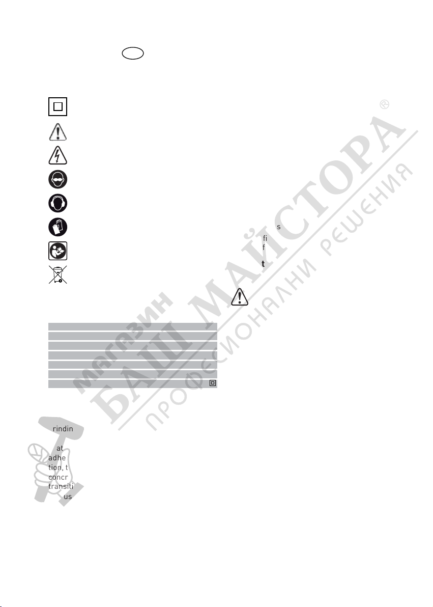
1 Symbols
Double insulation
Warning of general danger
Risk of electric shock
Use protective goggles!
Wear ear protection!
Use protective gloves!
Read the instructions
Not to be included in municipal refuse
Advice or tip
2 Technical data
Nominal voltage 220-240 V ~
Mains frequency 50 / 60 Hz
Power input 1100 W
Adjustable revolutions 2000 – 5900 min
Tool diameter 80 mm
Weight 3.2 kg
Protection class II /
–1
3 Prescribed usage
The machine works on the principle of an angle
grinder but uses also special tools for milling and
grinding, e.g. of concrete and plaster.
The machine is intended for removal of paint
coats, plasters, residues of wall tile and carpet
adhesives mainly from rigid surfaces. In addition, the machine can be used for roughing of fl at
concrete surfaces and for milling of lining work
transitions.
The user proper is responsible for improper usage.
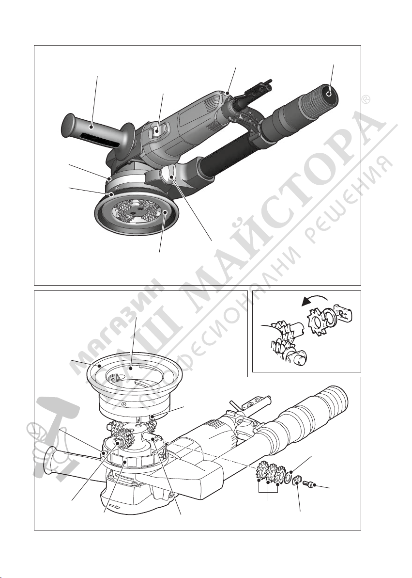
4 Control Elements
[1-1] Additional handle
[1-2] Switch lever
[1-3] Adjusting wheel
[1-4] Handle
[1-5] Knob
[1-6] Backstop bar
[1-7] Suction fl ange
[1-8] Scale
[2-1] Bolt
[2-2] Retainer
[2-3] Washer
[2-4] Milling rings
[2-5] Tool carrier
[2-6] Guide surface
[2-7] Bolt
[2-8] Sliding part
[2-9] Slot
[2-10] Suction fl ange
[2-11] Guide surface
Accessories that are illustrated or described here
are not always included in the scope of delivery.
The specifi ed illustrations can be found at the beginning of the operating instructions.
5 Notes on Safety Prevention
5.1 General safety instructions
WARNING! Read all safety warnings and
all instructions. Failure to follow the warn-
ings and instructions may result in electric
shock, fi re and/or serious injury.
Save all warnings and instructions for future
reference.
The term „power tool“ in the warnings refers to
your mains-operated (corded) power tool or battery-operated (cordless) power tool.
5.2 Safety instructions for all operations
Safety Warnings Common for grinding, surface
grinding, grinding with wire brush or ABRASIV
cutting:
a) This power tool is intended to function as
a surface grinder or a cutter with a cutter
head. Read all safety warnings, instructions,
illustrations and specifications provided with
this power tool. Failure to follow all instruc-
tions listed below may result in electric shock,
fi re and/or serious injury.
b) Operations such as polishing or cutting are
not recommended to be performed with this
power tool. Operations for which the power
tool was not designed may create a hazard and
cause personal injury.
c) Do not use accessories which are not specifi -
cally designed and recommended by the tool
11
Page 4

manufacturer. Just because the accessory can
be attached to your power tool, it does not assure safe operation.
d) The rated speed of the accessory must be at
least equal to the maximum speed marked
on the power tool. Accessories running faster
than their rated speed can break and fl y apart.
e) The outside diameter and the thickness of
your accessory must be within the capacity
rating of your power tool. Incorrectly sized
accessories cannot be adequately guarded or
controlled.
f) The arbour size of wheels, fl anges, backing
pads or any other accessory must properly fi t
the spindle of the power tool. Accessories with
arbour holes that do not match the mounting
hardware of the power tool will run out of balance, vibrate excessively and may cause loss
of control.
g) Do not use a damaged accessory. Before each
use inspect the accessory such as ABRASIV
wheels for chips and cracks, backing pad for
cracks, tear or excess wear, wire brush for
loose or cracked wires. If power tool or accessory is dropped, inspect for damage or
install an undamaged accessory. After inspecting and installing an accessory, position yourself and bystanders away from the
plane of the rotating accessory and run the
power tool at maximum no-load speed for one
minute. Damaged accessories will normally
break apart during this test time.
h) Wear personal protective equipment. Depend-
ing on application, use face shield, safety goggles or safety glasses. As appropriate, wear
dust mask, hearing protectors, gloves and
workshop apron capable of stopping small
ABRASIV or workpiece fragments. The eye
protection must be capable of stopping fl ying
debris generated by various operations. The
dust mask or respirator must be capable of
fi ltrating particles generated by your operation.
Prolonged exposure to high intensity noise may
cause hearing loss.
i) Keep bystanders a safe distance away from
work area. Anyone entering the work area
must wear personal protective equipment.
Fragments of workpiece or of a broken accessory may fl y away and cause injury beyond immediate area of operation.
j) Hold power tool by insulated gripping surfaces
only, when performing an operation where the
cutting accessory may contact hidden wiring
12
or its own cord. Cutting accessory contacting a
“live” wire may make exposed metal parts of
the power tool “live” and shock the operator.
k) Position the cord clear of the spinning acces-
sory. If you lose control, the cord may be cut or
snagged and your hand or arm may be pulled
into the spinning accessory.
l) Never lay the power tool down until the acces-
sory has come to a complete stop. The spin-
ning accessory may grab the surface and pull
the power tool out of your control.
m
) Do not run the power tool while carrying it at
your side. Accidental contact with the spinning
accessory could snag your clothing, pulling the
accessory into your body.
n) Regularly clean the power tool’s air vents. The
motor’s fan will draw the dust inside the housing and excessive accumulation of powdered
metal may cause electrical hazards.
o) Do not operate the power tool near fl ammable
materials. Sparks could ignite these materials.
p) Do not use accessories that require liquid
coolants. Using water or other liquid coolants
may result in electrocution or shock.
Further safety instructions for all operations
Kickback and Related Warnings
Kickback is a sudden reaction to a pinched or
snagged rotating wheel, backing pad, brush or
any other accessory. Pinching or snagging causes
rapid stalling of the rotating accessory which in
turn causes the uncontrolled power tool to be
forced in the direction opposite of the accessory’s
rotation at the point of the binding.
For example, if an ABRASIV wheel is snagged or
pinched by the workpiece, the edge of the wheel
that is entering into the pinch point can dig into
the surface of the material causing the wheel to
climb out or kick out. The wheel may either jump
toward or away from the operator, depending on
direction of the wheel’s movement at the point of
pinching. ABRASIV wheels may also break under
these conditions.
Kickback is the result of power tool misuse and/
or incorrect operating procedures or conditions
and can be avoided by taking proper precautions
as given below.
a) Maintain a firm grip on the power tool and
position your body and arm to allow you to
resist kickback forces. Always use auxiliary
handle, if provided, for maximum control over
kickback or torque reaction during start-up.
The operator can control torque reactions or
Page 5

kickback forces, if proper precautions are taken.
b) Never place your hand near the rotating ac-
cessory. Accessory may kickback over your
hand.
c) Do not position your body in the area where
power tool will move if kickback occurs. Kickback will propel the tool in direction opposite to
the wheel’s movement at the point of snagging.
d) Use special care when working corners, sharp
edges etc. Avoid bouncing and snagging the
accessory. Corners, sharp edges or bouncing
have a tendency to snag the rotating accessory
and cause loss of control or kickback.
e) Do not attach a saw chain woodcarving blade
or toothed saw blade. Such blades create frequent kickback and loss of control.
Additional safety instructions for grinding and
cutting
Safety Warnings Specifi c for Grinding and
ABRASIV Cutting-Off Operations:
a) Use only wheel types that are recommended
for your power tool and the specifi c guard
designed for the selected wheel. Wheels for
which the power tool was not designed cannot
be adequately guarded and are unsafe.
b) The guard must be securely attached to the
power tool and positioned for maximum safety, so the least amount of wheel is exposed
towards the operator. The guard helps to pro-
tect operator from broken wheel fragments
and accidental contact with wheel.
c) Wheels must be used only for recommended
applications. For example: do not grind with
the side of cut-off wheel. ABRASIV cut-off
wheels are intended for peripheral grinding,
side forces applied to these wheels may cause
them to shatter.
d) Always use undamaged wheel fl anges that
are of correct size and shape for your selected
wheel. Proper wheel fl anges support the wheel
thus reducing the possibility of wheel breakage. Flanges for cut-off wheels may be different from grinding wheel fl anges.
e) Do not use worn down wheels from larger
power tools. Wheel intended for larger power
tool is not suitable for the higher speed of a
smaller tool and may burst.
Additional safety instructions for wire brushing
operations
Safety Warnings Specifi c for Wire Brushing
Operations:
a) Be aware that wire bristles are thrown by the
brush even during ordinary operation. Do not
overstress the wires by applying excessive
load to the brush. The wire bristles can easily
penetrate light clothing and/or skin.
b) If the use of a guard is recommended for wire
brushing, do not allow any interference of the
wire wheel or brush with the guard. Wire wheel
or brush may expand in diameter due to work
load and centrifugal forces.
Further safety instructions
- The machine may not be used in damp and wet
spaces, outdoor when it is rainy, foggy or snowy
or in the explosive environment.
- Before use always inspect the fl exible lead and
the plug. Have the defects repaired by a specialist repair shop.
- Outside the premise use only approved exten-
sion leads and cable connections.
- Apply the machine to the material only when
switched on.
- Do not carry the machine by the lead.
- Do not work on a ladder.
- When operating the tool, use protective gloves
and tough footwear.
- When operating the tool, use goggles and ear
protectors.
- The dust generated during work is harmful to
health. When operating the tool, use the dust
extraction system and the respirator.
- Materials containing asbestos can only be pro-
cessed by qualifi ed individuals. Comply with the
safety regulations that apply in your country.
- Flexible power supply cable always route from
the tool backwards.
- Only use milling rings recommended by the
manufacturer.
- The machine is only allowed be used when pro-
tective guard is in place and additional handle
is fastened.
- Plug in the fl exible power supply cable’s plug
into the wall socket when the machine is off.
- Make yourself sure whether the material that is
going to be machined does not contain electric,
water or gas lines – an injury could occur.
- Do not mill over metal objects, nails or screws.
13
Page 6

- The machine is not allowed to be operated by a
person under 16 years of age.
- Only for AS/NZS: The tool shall always be sup-
plied via residual current device with a rated residual current of 30 mA or less.
5.3 Emission levels
Measured values determined according to EN 60 745.
Typically the A-weighted noise level of the tool are:
Sound pressure level: 86 dB (A)
Sound power level: 97 dB (A)
Inaccuracy of measurement K = 1.5dB (A)
CAUTION
Operating noise
Damage to hearing
Use ear protection!
Measured values determined according to EN 60 745.
Grinding with grinding wheel ah = 5.3 m/s2
Inaccuracy of measurement K = 1.5 m/s²
The specifi ed emissions values (vibration, noise)
– are used to compare machines.
– They are also used for making preliminary estimates regarding vibration and noise loads during
operation.
– They represent the primary applications of the
power tool.
Increase possible for other applications, with other insertion tools or if not maintained adequately.
Take note of idling and downtimes of machine!
6 Activation
WARNING
Risk of accident if the machine is operated using unauthorised voltages or frequencies.
The mains voltage and the frequency of the
power source must correspond with the
specifi cations on the machine’s name plate.
In North America, only Festool machines with
the voltage specifi cations 120 V/60 Hz may
be used.
61 Switching on – off
Switching on
Move the switch button [1-2] forward and the device will switch on. If you press the front part of the
button, it will arrest and start continual operation.
14
Switching off
Press the rear part of the button [1-2] to relax ar-
rest. The button returns to switched-off position.
6.2 Motor electronics
Starting current limitation
Electronically controlled continual running secures device acceleration without back thrust.
Due to starting current limitation in the device,
15A protection is suffi cient.
WARNING
Devices without starting current limitation
need higher protection – at least 16A circuit
breaker.
Switching off during back thrust
During sudden drop of revolutions, for example
blocking in dividing cut, the current input in motor stops. For re-starting, the device must be fi rst
switched off and again switched on.
Protection against re-starting
Prevent uncontrolled starting of the device after
current supply cut off. For re-starting, the device
must be fi rst switched off and again switched on.
Revolutions pre-setting
Use the revolutions regulator [1-3] for smooth
revolutions pre-setting.
Degree 1: 2000 min–1 Degree 4: 4500 min
Degree 2: 2950 min–1 Degree 5: 5300 min
Degree 3: 3750 min–1 Degree 6: 5900 min
Required number of revolutions depends on applied grinding wheel and worked material.
Constant electronics
Constant electronics maintains revolutions during
operation and idle run near the constant. Regular
operating shift is achieved.
Protection from overloading dependant on
temperature
The safety electronics switches to cooling regime
when the critical temperature is reached. Motor
continues running at approximately 2500 min
revolutions, constant electronics is deactivated.
After cooling to approximately 10 – 20 s, the device
is fully operational.
Heat protection for devices heated during operation, reacts adequately sooner.
–1
–1
–1
–1
Page 7

7 Milling tools
7.1 Choice of cutter and grinding head
According to use and type of application, there are
various types of cutter heads. To achieve optimal
work results, use suitable grinding heads.
Data in the Chart showing speed pre-selection
options are recommended values only; practice
testing should be always performed – see page
19!
7.2 Cutter / Grinding head change
Before putting into operation, check perfect run
of the cutter tool: turn it manually.
Make sure that all screws are tightened up well.
Four screws connecting the fl ange and the head
tool should be well-tightened up: use torque 5
Nm.
Two screws fi xing the position of the head on the
machine should be well-tightened up: use torque
8 Nm.
Do not leave any tools inserted in.
7.3 Replacing Grinding Wheels
WARNING
Risk of accident, electric shock
Always pull the plug out of the socket before
performing any type of work on the machine.
If teeth of milling rings that are made of hard alloy
are worn, it is possible to replace them.
By means of turning the knob [1-5] release the
clamping belt to such extent so as it is possible
to move the suction fl ange [1-7].
Turn the suction fl ange fully counter-clockwise
and pull it downwards.
Release two bolts [2-1], [2-7] on four axes of
tool carrier using the hexagonal spanner S4.
Now, the milling cutters are easily accessible.
When replacing milling rings replace also bolts
[2-1], [2-7] and excessive turn retainers [22]. The bolts have been fi xed by light adhesive
agent so as they cannot be loosened by vibrations. Only use originally supplied bolts.
Firstly, put three milling rings [2-4] onto each
axis, then the washer [2-3]; fasten everything
with the help of excessive turn retainer [2-2]
and bolts [2-1], [2-7]. It is extremely important
that you insert the excessive turn retainer into
corresponding slot [2-5] located in tool carrier
axis. If the excessive turn retainers are not installed, bolts could be loosened during operation; this may cause major losses.
Put on the suction fl ange [2-10] so as sliding
parts [2-8] snap into corresponding slots [2-9]
located on suction fl ange.
Set the milling depth required and tighten the
clamping belt using the turning knob.
When installing the model with fl at teeth, it is important that milling rings are installed as shown
in the Fig. [3]; it means that tips must be oriented
in the direction of milling head rotation.
The model with spiked teeth (HW-SZ 12) is used
to remove old layers of paint from concrete or
plasters. The version with fl at teeth (HW-FZ 12)
is used for smoothening of timbering gaps and
for machining of concrete edges.
8 Operation
When operating with renovation cutter, you
must use goggles so as you protect your eyes
from fl ying material particles!
Adjustable height of suction fl ange is necessary
to be adapted to mode of use. When removing old
layers of paints, tips of teeth would not overlap
the suction fl ange by more than 1 mm. In the contrary, when milling plasters, the milling rings can
overlap by 2 to 4 mm. To adjust the height, slightly
release the clamping belt using the turning knob
[1-5] and turn the suction fl ange [1-7] counter-
clockwise or clockwise. Adjustable range is up to
5.5 mm. The milling depth adjusted can be roughly
read on the scale [1-8]. If height adjustment does
not operate smoothly, we recommend cleaning
the guide surfaces [2-6] and [2-11]. Once the
height is adjusted, fasten tight the clamping belt.
Do not ever operate the machine without suction fl ange! Only remove it when cleaning the
guide surfaces or when replacing milling rings.
When carrying out these operations, always
remove the plug from wall socket!
The suction fl ange can be also used on machined
area as a holder [1-6]. On principle, the renovation cutter should be applied fl atwise onto the
work piece. In case of fl at surfaces, optimum adjustment is 6
WARNING
CAUTION
th
step of the Electronic.
15
Page 8

CAUTION
During work, inspect whether milling rings
still freely rotate on axes. If it is not the case,
e.g. due to accumulated dust; it is necessary
to remove it from the milling head. For this
reason the machine should not be operated
without suction system connected!
8.1 Suction system
To ensure the operability of suction system, put
the hose (36 mm diameter) of some Festool brand
vacuum cleaner onto the handle adaptor [1-4].
Keep in mind that as fi ltration sack is being fi lled,
the suction effectiveness signifi cantly reduces.
Also clean vacuum cleaner’s fi lter time to time.
CAUTION
Always operate the machine with the suction
system connected; otherwise, the milling rings
as well as suction fl ange height adjustment
system will be clogged with dust!
To prevent discharges of static electricity in dusty
environment, use vacuum cleaners of antistatic
models only.
8.2 Additional handle
To operate the grinder with both hands, it is possible to fasten an additional handle [1-1] to the
left-hand side of gearbox cover’s front part.
The special “VIBRASTOP” design reduces vibrations in the additional handle.
9 Service and maintenance
Risk of accident, electric shock
Always pull the plug out of the socket before
performing any type of work on the machine.
All maintenance and repair work which re-
quires the motor housing to be opened, must
only be carried out by an authorised service
workshop.
WARNING
- To ensure the airfl ow is suffi cient, cooling open-
ings of the motor must be always clean and free.
- The machine is equipped with special self-
disconnecting brushes. When the brushes are
worn, the power supply is automatically disconnected, and the machine is stopped.
- If the suction fl ange height adjustment system
does not operate smoothly, the fl ange must be
removed and cleaned.
Customer service and repair. Only
through manufacturer or service
workshops: Please find the nearest
address at: www.festool.net/service
EKAT
4
Use only original Festool spare parts!
5
3
2
Order No. at: www.festool.net/service
1
10 Environment
Do not throw the power tool in your household
waste! Dispose of the machine, accessories and
packaging at an environmentally-responsible recycling centre! Observe the valid national regulations.
EU only: In accordance with European Directive on
waste electrical and electronic equipment and implementation in national law, used electric power
tools must be collected separately and handed in
for environmentally friendly recycling.
Information on REACh:
www.festool.com/reach
11 EU Declaration of Conformity
Renovation Cutter Serial no.
RG 80 E 769231, 768829,
Year of CE mark: 2013
We declare under sole responsibility that this
product comply with all relevant requirements
of the following directives, norms or normative
documents:
2006/42/EC, 2004/108/EC, 2011/65/EU, EN 55
014-1, EN 55 014-2, EN 60 745-1, EN 60 745-2-3,
EN 61 000-3-2, EN 61 000-3-3.
Festool Group GmbH & Co. KG
Wertstr. 20, D-73240 Wendlingen
768798
- Wrapped electric tools can be stored in a dry
place without heating, with temperatures not
lower than –5°C. Unwrapped electric tools can
only be stored in dry places with temperatures
not lower than +5°C, without sudden changes
in the temperature.
16
Dr. Martin Zimmer 2013-04-15
Head of Research, Development and Technical
Documentation
Page 9

Cutter head Installation Application
Cutter head “Flat Shape” with
12 hard-metal cutter wheels
FZ-RG 80
Cutter head “Pointed Shape”
with 12 hard-metal cutter
wheels SZ-RG 80
Grinding head Installation Application
Diamond grinding head:
grinding wheel with 8
segments provided with
diamond grits DIA HARD-RG
80
Diamond grinding head:
grinding wheel with 8
segments provided with
diamond grits DIA ABRASIVRG 80
Diamond grinding head
DIA THERMO-RG 80
- Plaster removal
- Removing of elastic protective coats on walls
and fl ooring
- Removing of foam base and glue remnants
(carpet remnants)
- Removing of fl oor tile glue remnants
- Removing of bitumen and concrete protective
coats
- Removing of latex paints or oil paints on
gypsum surface
- Plaster removal
- Removing of bumps and excessive material
after boarding – fresh concrete work
- Removing of foam base and glue remnants (and
carpet remnants)
- Removing of fl oor tile glue remnants
- Removing of plaster made of synthetic resin
(made on thermal insulation)
- Removing of bumps and excessive material –
screed fl oor cover
- Grinding and cleaning weather-worn parts of
concrete constructions
- Removing of bumps – old concrete
- Removing of bumps and excessive material –
screed fl oor cover
- Grinding and cleaning – fresh concrete
- Grinding – ABRASIV materials
- Tenacious and thermo-elastic materials, such as
paints, protective paints, elastic glue
Electronic
adjusting
wheel
4 – 6
4 – 6
Electronic
adjusting
wheel
6
6
5 – 6
Hard-metal grinding head:
grinding wheel provided with
hard-metal grits HW Grob-RG
80
Diamond grinding head,
ABRASIV disk with soldered
diamond grains DIA UNI-RG 80
Hard-metal grinding head:
grinding wheel provided with
hard-metal grits HW Fein-RG
80
- Removing of elastic protective coats on walls
and fl ooring
- Reduction of gypsum and cellular concrete
- Removing of impurities – concrete fl oors
- Removing of latex or oil paints – gypsum
surface
- Rough working
- Universal use, removal of paint from concrete,
hard plasters, wood, removal of elastic glues,
hard plasters, soft concrete
- Removing of elastic protective coats on walls
and fl ooring
- Reduction of gypsum and cellular concrete
- Removing of impurities – concrete surface
- Removing of latex or oil paints on gypsum
surface
- Fein working
3 – 5
5 – 6
3 – 5
17
 Loading...