

Page 1
Festool Group GmbH & Co. KG
Wertstraße 20
D-73240 Wendlingen
Tel.: +49 (0)7024/804-0
Telefax: +49 (0)7024/804-20608
www.festool.com
Originalbetriebsanleitung 8
Original operating manual
Notice d’utilisation d’origine 16
Manual de instrucciones original
Istruzioni per l'uso originali
Originele gebruiksaanwijzing 28
Originalbruksanvisning 32
Alkuperäiset käyttöohjeet 35
Original brugsanvisning 39
Originalbruksanvisning 43
Manual de instruções original 47
Оригинал Руководства по эксплуатации 51
Originál návodu k obsluze 55
Oryginalna instrukcja eksploatacji 58
12
20
24
768333_001
DR 20 E
Page 2
1
1-3
1-4
1-2
1-1
1-5
1-7
1-6
Page 3
2
klick
3 A
4 A
4 C
3 B
1
1
2
2
4 B
1
2
1
2
4 D
1
2
1
2
Page 4
5
1
3
2
4
Page 5
6 A
7
6 B
2
1
1
2
Page 6
8
1
8-1
2
9
9-1
10
10-1
45 °
45 °
Page 7
11 A
11 B
X
11-1
X
Page 8
DR 20 E
D
Originalbetriebsanleitung
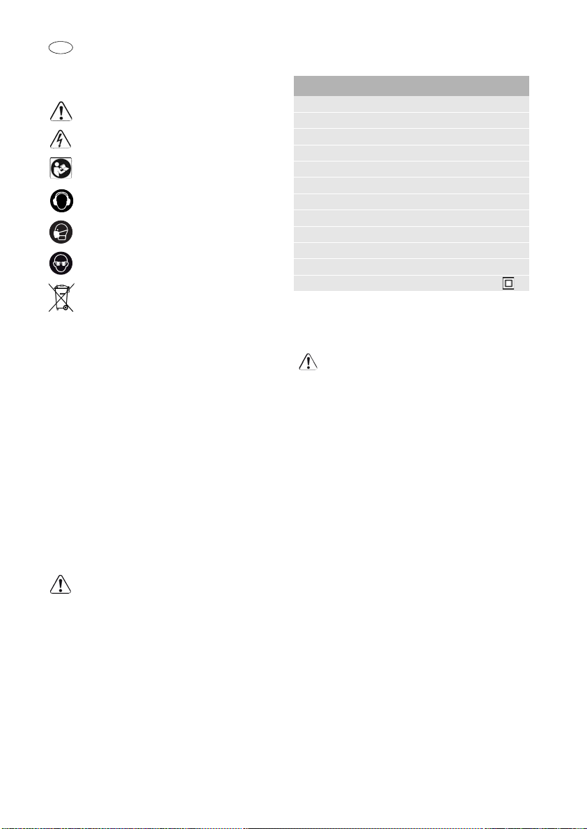
1Symbole
Warnung vor allgemeiner Gefahr
Warnung vor Stromschlag
Anleitung/Hinweise lesen!
Gehörschutz tragen!
Atemschutz tragen!
Schutzbrille tragen!
Nicht in den Hausmüll geben.
4 Technische Daten
Bohrmaschine DR 20 E
Leistung 1100 W
Leerlaufdrehzahl 0 - 650 min
max. Drehmoment 98 Nm *
Bohrfutter-Spannbereich 3 - 16 mm
Werkzeugaufnahme in Bohrspindel 1/4 ’’
Bohrdurchmesser max.
Stahl 20 mm
Aluminium 28 mm
Holz 65 mm
Spannhals 57 mm
Gewicht 3,2 kg
Schutzklasse /II
* Blockiermoment elektronisch begrenzt
-1
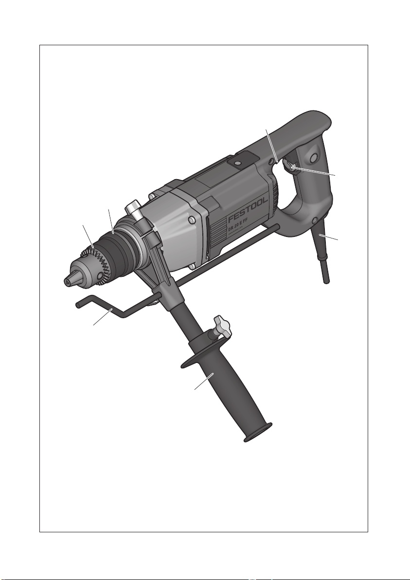
2 Geräteelemente
[1-1]
[1-2]
[1-3]
[1-4]
[1-5]
[1-6]
[1-7]
Die angegebenen Abbildungen befinden sich am
Anfang der Betriebsanleitung.
Bohrfutter
Entriegelungsring
Schalter für Rechts-/Links-Lauf
Ein-/Ausschalter
Netzanschlussleitung
Zusatzhandgriff
Tiefenanschlag
3 Bestimmungsgemäße Verwen-
dung
Bohrmaschine geeignet
– zum Bohren in Metall, Holz, Kunststoffen und
ähnlichen Materialien,
– zum Ein- und Festschrauben von Schrauben.
Bei nicht bestimmungsgemäßem Gebrauch
haftet der Benutzer.
5 Sicherheitshinweise
5.1 Allgemeine Sicherheitshinweise
Warnung! Lesen Sie sämtliche Sicherheits-
hinweise und Anweisungen.
Einhaltung der Warnhinweise und Anweisungen
können elektrischen Schlag, Brand und/oder
schwere Verletzungen verursachen.
Bewahren Sie alle Sicherheitshinweise und Anweisungen für die Zukunft auf.
Der in den Sicherheitshinweisen verwendete Begriff „Elektrowerkzeug“ bezieht sich auf netzbetriebene Elektrowerkzeuge (mit Netzkabel) und auf
akkubetriebene Elektrowerkzeuge (ohne Netzkabel).
5.2 Maschinenspezifische Sicherheitshin-
–
–
–
weise
Halten Sie das Gerät nur an den isolierten
Griffflächen, wenn Sie Arbeiten ausführen, bei
denen das Einsatzwerkzeug oder die Schraube
verborgene Stromleitungen oder das eigene
Netzkabel treffen kann.
satzwerkzeuges oder der Schraube mit einer
spannungsführenden Leitung kann auch metallene Geräteteile unter Spannung setzen und zu
einem elektrischen Schlag führen.
Benutzen Sie die mit dem Gerät gelieferten Zusatzhandgriffe.
zu Verletzungen führen.
Vermeiden Sie ein versehentliches Einschalten.
Das Tragen des Elektrowerkzeugs mit Ihrem Finger am Ein-/Ausschalter kann zu Unfällen führen.
Der Verlust der Kontrolle kann
Fehler bei der
Der Kontakt des Ein-
8
Page 9
–
Warten Sie, bis das Elektrowerkzeug zum Stillstand gekommen ist, bevor Sie es ablegen.
Das
Einsatzwerkzeug kann sich verhaken und zum
Verlust der Kontrolle über das Elektrowerkzeug
führen.
–
Das Gerät darf nicht nass sein oder in feuchter
Umgebung betrieben werden.
Schließen Sie Geräte, die im freien verwendet werden, über einen
Fehlerstrom-Schutzschalter (FI-) mit maximal
30mA Auslösestrom an. Nur ein für Aussenbereich zugelassenes Verlängerungskabel verwenden.
–
Tragen Sie geeignete persönliche Schutzausrüstungen:
Gehörschutz, Schutzbrille, Staubmaske bei stauberzeugenden Arbeiten,
Schutzhandschuhe beim Bearbeiten rauer Materialien und beim Werkzeugwechsel.
– Regelmäßig den Stecker und das Kabel prüfen
um eine Gefährdung zu vermeiden, und diese bei
Beschädigung von einer autorisierten Kundendienst-Werkstätte erneuern lassen.
– Führen Sie das Kabel immer nach hinten von der
Maschine weg.
– Achten Sie beim Bohren in Wände auf eventuell
vorhandene Gas-, Strom- oder Wasserleitungen.
VORSICHT! Rückschlag!
Drehung: Gerät sofort ausschalten!
5.3 Emissionswerte
Die nach EN 60745 ermittelten Werte betragen typischerweise:
Schalldruckpegel L
= 88 dB(A)
PA
Schallleistungspegel LWA = 99 dB(A)
Unsicherheit K = 3 dB
VORSICHT
Beim Arbeiten eintretender Schall
Schädigung des Gehörs
Benutzen Sie einen Gehörschutz!
Schwingungsemissionswert a
dreier Richtungen) und Unsicherheit K ermittelt
entsprechend EN 60745:
Bohren in Metall a
Schrauben ah = 2,6 m/s
(Vektorsumme
h
= 2,6 m/s
h
K = 1,5 m/s
K = 1,5 m/s
DR 20 E
Die angegebenen Emissionswerte (Vibration, Geräusch)
– dienen dem Maschinenvergleich,
– eignen sich auch für eine vorläufige Einschät-
zung der Vibrations- und Geräuschbelastung
beim Einsatz,
– repräsentieren die hauptsächlichen Anwendun-
gen des Elektrowerkzeugs.
Erhöhung möglich bei anderen Anwendungen, mit
anderen Einsatzwerkzeugen oder ungenügend gewartet. Leerlauf- und Stillstandszeiten der Maschine beachten!
6 Inbetriebnahme
WARNUNG
Unzulässige Spannung oder Frequenz!
Unfallgefahr
Angaben auf Typenschild beachten.
Länderbesonderheiten beachten.
Ein-/Ausschalter [1-4]
Drücken = EIN, Loslassen = AUS
Je nach Druck auf den Ein-/Ausschalter ist die
Drehzahl stufenlos steuerbar.
7 Einstellungen
7.1 Drehrichtung ändern [1-3]
• Schalter nach links = Rechtslauf
• Schalter nach rechts = Linkslauf
8 Werkzeugaufnahme, Vorsatzgeräte
WARNUNG
Verletzungsgefahr, Stromschlag
Vor allen Arbeiten an der Maschine stets den
Netzstecker aus der Steckdose ziehen!
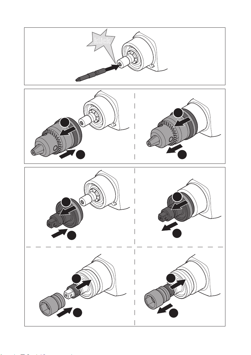
8.1 Werkzeugaufnahme in der Bohrspindel
Bits können direkt in der Innensechskantaufnahme
der Bohrspindel eingesetzt werden.
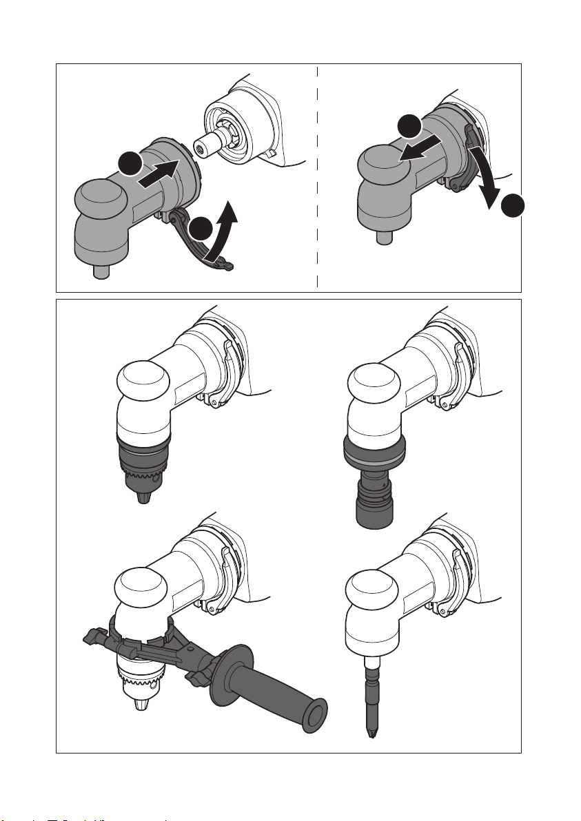
8.2 Bohrfutter [1-1]
Das Bohrfutter
Bohrern
2
2
2
2
[2]
[5]
und Bits.
[1-1]
dient zum Einspannen von
D
9
Page 10
DR 20 E
D
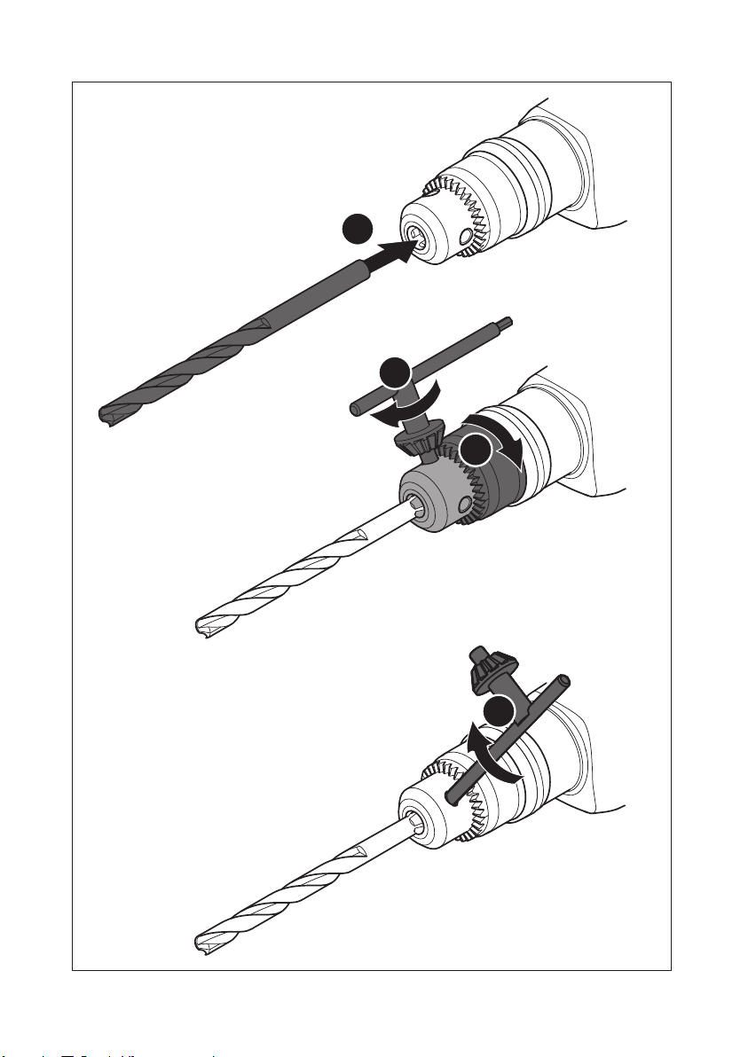
VORSICHT
Verlet zung sgef ahr
Spannen Sie das Werkzeug zentrisch im Bohrfutter ein!
Vor dem ersten Gebrauch:
Bohrspindel mit etwas Mehrzweckfett.
Bohrfutter montieren [3 A]
Bohrfutter demontieren [3 B]
Bohrer wechseln [5]
8.3 Steckschlüsseladapter [4]
Auf den Steckschlüsseladapter (teilweise Zubehör)
können Steckschlüssel (Nüsse) aufgesteckt werden.
Steckschlüsseladapter montieren [4 A]
Steckschlüsseladapter demontieren [4 B]
Steckschlüssel montieren [4 C]
Steckschlüssel demontieren [4 D]
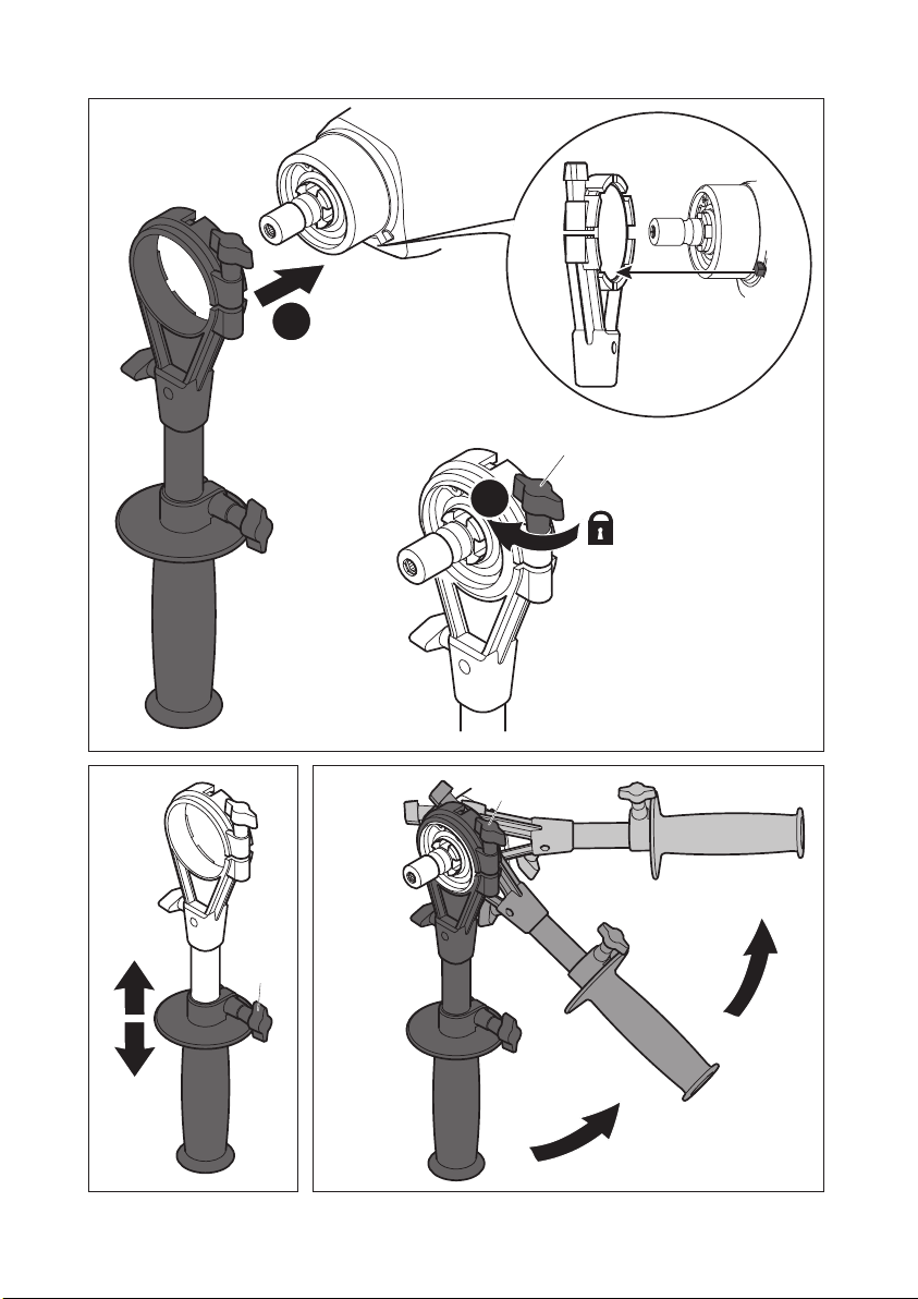
8.4 Winkelkopf [6] + [7]
Der Winkelkopf (teilweise Zubehör) ermöglicht
Bohren und Schrauben im rechten Winkel zur Maschine.
Vor dem ersten Gebrauch:
Bohrspindel und den Getriebehals mit etwas
Mehrzweckfett.
Winkelkopf montieren [6 A]
Winkelkopf demontieren [6 B]
8.5 Zusatzhandgriff [1-6]
Immer Zusatzhandgriff
eine sichere und ermüdungsarme Arbeits-
haltung zu gewährleisten.
Zusatzhandgriff montieren [8]
Zusatzhandgriff
[1-6]
häuses aufsetzen, bis die Aussparungen am Zusatzhandgriff in die Nase am Gehäuse einrasten.
Flügelschraube
[1-6]
gegen Uhrzeigersinn drehen bis dieser
[8-1]
fest sitzt.
Mit der Flügelschraube
des Zusatzhandgriffs
[9]
.
Durch Drehen der Flügelschraube
die Position in 45°-Schritten verstellt werden
[10]
.
Bestreichen Sie die
Bestreichen Sie die
[1-6]
verwenden um
am Hals des Getriebege-
des Zusatzhandgriffs
[9-1]
kann die Länge
[1-6]
eingestellt werden
[10-1]
kann
Demontage in umgekehrter Reihenfolge.
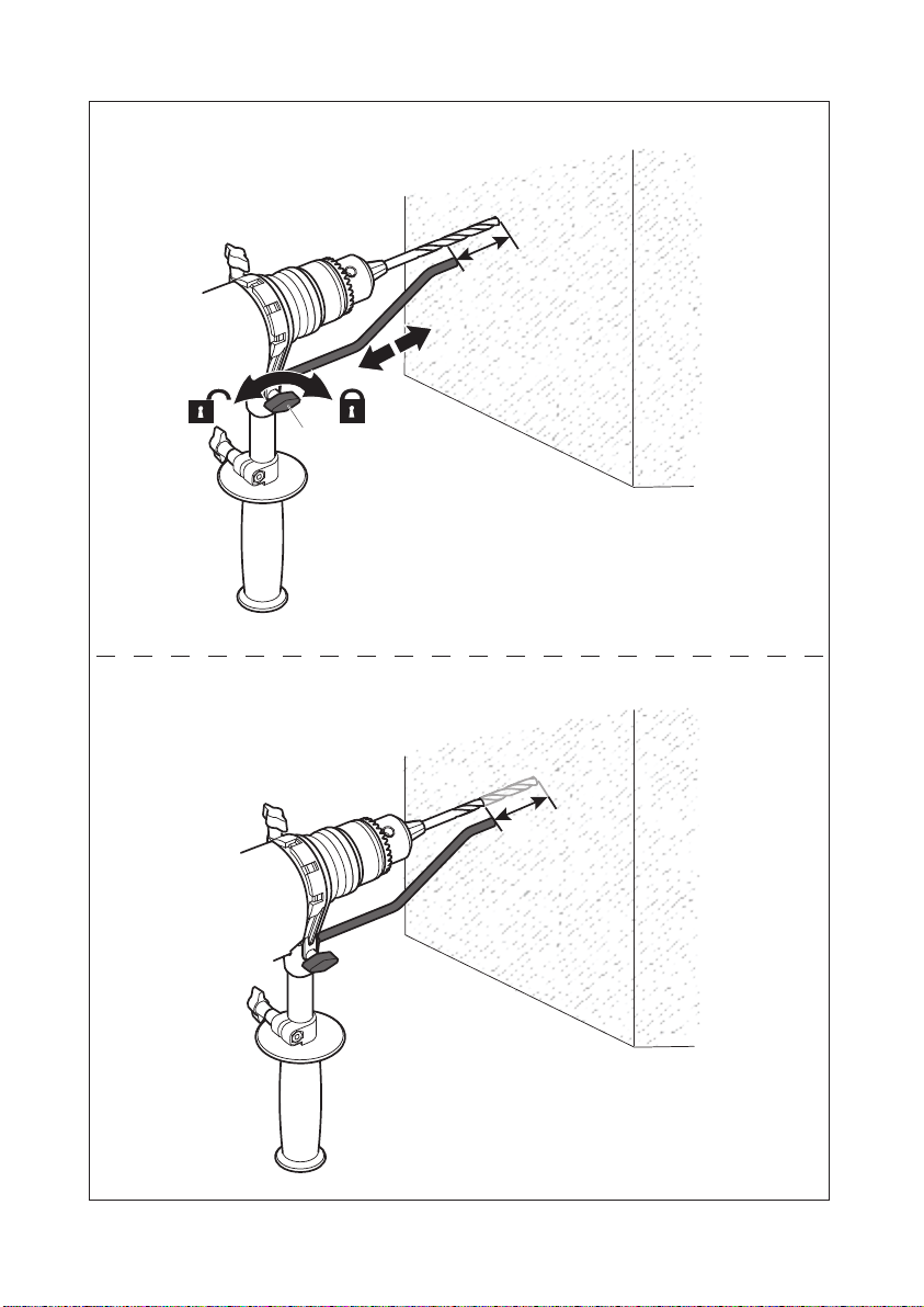
8.6 Tiefenanschlag [1-7]
Mit dem Tiefenanschlag
[1-7]
kann die Bohrtiefe
eingestellt werden.
Tiefenanschlag montieren [11 A]
Flügelschraube
[1-6]
durch Drehen gegen Uhrzeigersinn auf-
[11-1]
des Zusatzhandgriffs
drehen.
Tiefenanschlag
[1-7]
in Zusatzhandgriff
[1-6]
einsetzen.
Tiefenanschlag
[1-7]
so weit herausziehen,
dass Abstand zwischen Bohrerspitze und Spitze
von Tiefenanschlag gewünschter Bohrtiefe entspricht.
Flügelschraube
[1-6]
wieder festziehen.
[11-1]
des Zusatzhandgriffs
Demontage in umgekehrter Reihenfolge.
9 Wartung und Pflege
WARNUNG
Verletzungsgefahr, Stromschlag
Vor allen Wartungs- und Pflegearbeiten stets
den Netzstecker aus der Steckdose ziehen!
Alle Wartungs- und Reparaturarbeiten, die ein
Öffnen des Motorgehäuses erfordern, dürfen
nur von einer autorisierten Kundendienstwerkstatt durchgeführt werden.
Kundendienst und Reparatur
nur
durch Hersteller oder durch Servicewerkstätten: Nächstgelegene Adresse
unter:
www.festool.com/Service
EKAT
4
Nur original Festool Ersatzteile verwenden! Bestell-Nr. unter:
5
3
2
1
www.festool.com/Service
Folgende Hinweise beachten:
– Die Lüftungsöffnungen am Elektrowerkzeug frei
und sauber halten, damit die Kühlung gewährleistet ist.
– Die Anschlusskontakte am Elektrowerkzeug, La-
degerät und Akkupack sauber halten.
10 Zubehör
Nur von Festool zugelassenes Zubehör und Verbrauchsmaterial verwenden. Siehe Festool-Katalog oder www.festool.com.
10
Page 11
11 Umwelt
Gerät nicht in den Hausmüll werfen!
Geräte, Zubehör und Verpackungen
einer umweltgerechten Wiederverwertung zuführen. Geltende nationale
Vorschriften beachten.
Nur EU:
Gemäß Europäischer Richtlinie 2002/96/EG
müssen verbrauchte Elektrogeräte getrennt gesammelt und einer umweltgerechten Wiederverwertung zugeführt werden.
Informationen zur REACh: www.festool.com/reach
12 EG-Konformitätserklärung
Bohrmaschine Serien-Nr.
DR 20 E 768485
Jahr der CE-Kennzeichnung: 2013
DR 20 E
D
Wir erklären in alleiniger Verantwortung, dass dieses Produkt mit allen relevanten Anforderungen
folgender Richtlinien, Normen oder normativen
Dokumenten übereinstimmt:
2006/42/EG, 2004/108/EG, 2011/65/EU, EN 60745-1,
EN 60745-2-1, EN 60745-2-2, EN 55014-1, EN
55014-2, EN 61000-3-2, EN 61000-3-3.
Festool Group GmbH & Co. KG
Wertstr. 20, D-73240 Wendlingen
Dr. Martin Zimmer
Leiter Forschung, Entwicklung, technische Doku-
mentation
2013-05-02
11
Page 12
DR 20 E
GB
Original operating manual
1Symbols
Warning of general danger
Risk of electric shock
Read the Operating Instructions/Notes!
Wear ear protection.
Wear a dust mask.
Wear protective goggles.
Do not throw in the household waste.
4Technical data
Drill DR 20 E
Power 1100 W
Idling speed 0 - 650 rpm
Max. torque 98 Nm *
Chuck clamping range 3 - 16 mm
Tool holder in drill spindle 1/4 ’’
Drill diameter max.
Steel 20 mm
Aluminium 28 mm
Wood 65 mm
Flange 57 mm
Weight 3,2 kg
Safety class /II
* Static torque electronically limited
2 Machine features
[1-1]
[1-2]
[1-3]
[1-4]
[1-5]
[1-6]
[1-7]
The specified illustrations appear at the beginning
of the Operating Instructions.
Chuck
Release ring
Right/left switch
On/Off switch
Mains power cable
Additional handle
Depth stop
3 Intended use
Drill suitable
– for drilling in metal, wood, plastics and similar
materials,
– for screwing in and tightening screws.
The user is liable for improper or non-intended use.
5 Safety instructions
5.1 General safety instructions
WARNING! Read all safety warnings and all
instructions.
and instructions may result in electric shock, fire
and/or serious injury.
Save all warnings and instructions for future reference.
The term "power tool" in the warnings refers to
your mains-operated (corded) power tool or battery-operated (cordless) power tool.
5.2 Machine-related safety instructions
–
Hold power tool by insulated gripping surfaces,
when performing an operation where the cutting accessory or fastener may contact hidden
wiring or its own cord.
teners contacting a "live" wire may make exposed
metal parts of the power tool "live" and could give
the operator an electric shock.
–
Use auxiliary handles supplied with the tool.
Loss of control can cause personal injury.
Avoid unintentional activation.
–
electric power tool with your fingers on the on/off
switch can lead to accidents.
–
Wait until the power tool stops completely until
placing it down.
and lead to a loss of control of the power tool.
–
The machine must never be operated when wet
or located in a damp environment.
vices that you intend to use outdoors via an earth
leakage circuit breaker (FI) with a maximum re-
Failure to follow the warnings
Cutting accessory or fas-
Carrying the
The tool can become entangled
Connect de-
12
Page 13
lease current of 30mA. Always use a cable approved for outdoor use.
Wear suitable protection:
–
such as ear protection, safety goggles, a dust mask for work which
generates dust, and protective gloves when
working with raw materials and when changing
tools.
– Check the plug and the cable regularly and
should either become damaged, in order to avoid
a hazard, have them replaced by an authorised
after-sales service workshop.
– Always guide the cable backwards away from the
machine.
– Take care when drilling into walls as there is a
danger of rupturing concealed gas/water pipes
or cutting through power cables.
–
Only for AS/NZS:
The tool shall always be supplied via residual current device with a rated residual current of 30 mA or less.
CAUTION! Rebound!
Rotation: Switch off device immediately!
5.3 Emission levels
Levels determined in accordance with EN 60745 are
typically:
Sound pressure level L
= 88 dB(A)
PA
Noise level LWA = 99 dB(A)
Measuring uncertainty allow-
K = 3 dB
ance
CAUTION
Operating noise
Damage to hearing
Use ear protection!
Vibration emission value a
directions) and uncertainty K measured in accordance with EN 60745:
Drilling in metall a
Fastening ah = 2,6 m/s
The specified emissions values (vibration, noise)
(vector sum for three
h
= 2,6 m/s
h
K = 1,5 m/s
K = 1,5 m/s
DR 20 E
– are used to compare machines.
– They are also used for making preliminary esti-
mates regarding vibration and noise loads during
operation.
– They represent the primary applications of the
power tool.
Increase possible for other applications, with other
insertion tools or if not maintained adequately. Take
note of idling and downtimes of machine!
6Operation
WARNING
Unauthorised voltage or frequency!
Risk of accidents
Observe the specifications on the machine’s
name plate.
Observe country-specific regulations.
On/off switch [1-4]
Press = ON, release = OFF
The speed of the machine depends on how far
the on/off switch is pressed in.
7Settings
7.1 Changing the rotational direction[1-3]
• Switch to the left = clockwise
• Switch to the right = anticlockwise
8 Tool holder, attachments
WARNING
Risk of injury, electric shock
Always pull the mains plug out of the socket before performing any type of work on the machine!
8.1 Tool holder in the drill spindle [2]
Bits can be inserted directly into the hexagon socket holder of the drill spindle.
8.2 Chuck [1-1]
2
The chuck
2
and screwdriver bits.
2
2
Risk of injury
[1-1]
is used for clamping drill bits
CAUTION
Clamp the tool centrally in the chuck!
GB
[5]
13
Page 14
DR 20 E
GB
Prior to initial use:
apply some multi-purpose
grease to the drill spindle.
Fit the chuck [3 A]
Remove the chuck [3 B]
Change the drill bit [5]
8.3 Socket spanner adapter[4]
Socket wrenches (sockets) can be attached to the
socket spanner adapter (partly as an accessory).
Fit socket spanner adapter [4 A]
Remove socket spanner adapter [4 B]
Fit socket wrench [4 C]
Remove socket wrench [4 D]
8.4 Angle attachment [6] + [7]
The angle attachment (partly as an accessory) allows the user to drill and fasten at right angles to
the machine.
Prior to initial use:
apply some multi-purpose
grease to the drill spindle and the gearbox neck.
Fit the angle attachment [6 A]
Remove the angle attachment [6 B]
8.5 Auxiliary handle [1-6]
Always use the additional handle
[1-6]
to
guarantee a safe, non-tiring working posture.
Attaching the additional handle [8]
Attach the additional handle
[1-6]
to the neck of
the gear housing until the recesses on the additional handle engage in the lug on the housing.
Turn the wing screw
additional handle
The wing screw
length of the additional handle
The position can be adjusted in 45° increments
[10]
by turning the wing screw
[8-1]
[1-6]
[9-1]
clockwise until the
is secured in position.
can be used to adjust the
[1-6][9]
[10-1]
.
.
Removal in reverse order.
8.6 Depth stop [1-7]
The drilling depth can be adjusted using the depth
stop
[1-7]
.
Attaching the depth stop [11 A]
Turn the wing screw
handle
[1-6]
anticlockwise to unscrew.
Insert the depth stop
dle
[1-6]
.
Pull out the depth stop
[11-1]
on the additional
[1-7]
in the additional han-
[1-7]
until the distance
between the tip of the drill and the tip of the
depth stop corresponds to the desired drilling
depth.
14
Tighten the wing screw
handle
[1-6]
again.
[11-1]
on the additional
Removal in reverse order.
9Service and maintenance
WARNING
Risk of injury, electric shock
Always disconnect the mains plug from the
socket before performing maintenance work on
the machine!
All maintenance and repair work which requires
the motor housing to be opened must only be
carried out by an authorised service workshop.
Customer service and repair
only
through manufacturer or service
workshops: Please find the nearest
address at:
www.festool.com/Service
EKAT
4
Use only original Festool spare parts!
Order No. at:
5
3
2
1
www.festool.com/Service
Note the following information:
– Keep the ventilation slits on the machine free and
clean to ensure adequate cooling.
– Keep the contacts on the machine, charger and
battery pack clean.
10 Accessories
Always use accessories and consumable materials
approved by Festool. See Festool catalogue or
www.festool.com.
11 Environment
Do not dispose of the device in household waste!
Recycle devices, accessories and packaging. Observe applicable country-specific regulations.
EU only:
European Directive 2002/96/
EC stipulates that used electric power tools must
be collected separately and disposed of at an environmentally responsible recycling centre.
Information on REACh:
www.festool.com/reach
12 EU Declaration of Conformity
Drill Serial no.
DR 20 E 768485
Year of CE mark: 2013
Page 15

We declare under sole responsibility that this product complies with all the relevant requirements in
the following Directives, standards and normative
documents:
2006/42/EC, 2004/108/EC, 2011/65/EU, EN 60745-1,
EN 60745-2-1, EN 60745-2-2, EN 55014-1, EN
55014-2, EN 61000-3-2, EN 61000-3-3.
Festool Group GmbH & Co. KG
Wertstr. 20, D-73240 Wendlingen, Germany
DR 20 E
GB
Dr. Martin Zimmer
Head of Research, Development and Technical
Documentation
2013-05-02
15
Page 16
DR 20 E
F
Notice d'utilisation d'origine
1Symboles
Avertissement de danger général
Risque d'électrocution
Lire les instructions / les remarques !
Portez des protège-oreilles!
Porter une protection respiratoire !
Porter des lunettes de protection !
Ne pas mettre aux déchets communaux!
2Composants de l’appareil
[1-1]
[1-2]
[1-3]
[1-4]
[1-5]
[1-6]
[1-7]
Les illustrations indiquées se trouvent au début de
la notice d'utilisation.
Mandrin de perçage
Bague de déverrouillage
Commutateur pour rotation à droite /
rotation à gauche
Interrupteur de marche/arrêt
Câble de raccordement secteur
Poignée additionnelle
Butée de profondeur
3 Utilisation en conformité avec les
instructions
Perceuse adaptée
– pour un perçage dans les matériaux suivants :
métal, bois, plastique et autres matériaux similaires,
– pour le vissage et le serrage de vis.
L'utilisateur est responsable des dommages
provoqués par une utilisation non conforme.
16
4 Caractéristiques techniques
Perceuse DR 20 E
Puissance 1100 W
Vitesse de rotation à vide 0 - 650
Couple max. 98 Nm *
Mandrin de perçage, plage de ser-
rage
Porte-outils dans la broche de per-
çage
Diamètre de perçage max.
Acier 20 mm
Aluminium 28 mm
Bois 65 mm
Collet 57 mm
Poids 3,2 kg
Classe de protection /II
* Couple de blocage à limitation électronique
tr/min
3 - 16 mm
1/4 ’’
5 Consignes de sécurité
5.1 Consignes générales de sécurité
Avertissement ! Veuillez lire toutes les
consignes de sécurité et instructions.
erreurs résultant du non-respect des consignes
d'avertissement et des instructions peuvent occasionner un choc électrique, des brûlures et/ou des
blessures graves.
Conservez toutes les consignes de sécurité et instructions pour une référence future.
Le terme "outil électrique" utilisé dans les
consigne de sécurité se rapporte aux outils électriques fonctionnant sur secteur (avec cordon d'alimentation) et aux outils électriques fonctionnant
sur accumulateurs (sans cordon d'alimentation).
5.2 Consignes de sécurité spécifiques à la
–
–
–
machine
Tenez l'appareil uniquement au niveau des surfaces isolées de la poignée lorsque vous effectuez des travaux au cours desquels l'outil de
série ou la vis peuvent toucher des conduites
électriques cachées ou le propre câble secteur.
Le contact de l'outil de série ou de la vis avec un
câble sous tension peut également mettre les
composants métalliques de l'outil sous tension et
provoquer un choc électrique.
Utilisez les poignées additionnelles fournies
avec l'appareil.
chine peut conduire à des blessures.
Éviter toute mise en marche par inadvertance.
Transporter l'outil électroportatif en gar-
La perte de contrôle de la ma-
Des
Page 17
dant le doigt sur l'interrupteur marche/arrêt
peut entraîner des accidents.
–
Arrêtez l'immobilisation complète de la machine électrique avant de la déposer.
L'outil
peut se bloquer et conduire à une perte de
contrôle de la machine électrique.
–
L'appareil ne doit être ni mouillé ni utilisé dans
des locaux humides.
Raccordez les outils utilisés
en extérieur à un disjoncteur différentiel de sécurité (FI) avec un seuil de déclenchement maximal de 30 mA. Utilisez exclusivement une
rallonge prévue pour un usage extérieur.
–
Porter des protections personnelles adéquates:
protection auditive, lunettes de protection,
masque pour les travaux générant de la poussière, gants de protection pour les travaux avec
des matériaux rugueux et pour le changement
d‘outils.
– Contrôler régulièrement le connecteur et le
câble pour éviter tout danger ; en cas d'endommagement, les faire remplacer par un des ateliers de service après-vente agréés.
– Toujours faire passer le cordon d'alimentation
par l'arrière de l'outil.
– Lors du perçage dans les murs, faites attention à
d'éventuelles conduites de gaz, de courant électrique ou d'eau.
ATTENTION ! Recul !
Rotation : mettre l'appareil immédiatement
hors tension !
5.3 Valeurs d'émission
Les valeurs mesurées selon la norme NE 60745
sont habituellement :
Niveau de pression acous-
LPA = 88 dB(A)
tique
Niveau de puissance acous-
tique
L
= 99 dB(A)
WA
Incertitude K = 3 dB
ATT ENT ION
Acoustique se produisant lors du travail
Endommagement de l'ouïe
Utilisez une protection acoustique !
DR 20 E
Valeur d'émission vibratoire a
tridirectionnelle) et incertitude K déterminées
(somme vectorielle
h
F
conformément à la norme EN 60745 :
Perçage dans le métal ah=2,6 m/s
K = 1,5 m/s
Vissage ah=2,6 m/s
K = 1,5 m/s
Les valeurs d'émission indiquées (vibration, bruit)
– sont destinées à des fins de comparaisons entre
les outils.
– Elles permettent également une estimation pro-
visoire de la charge de vibrations et de la nuisance sonore lors de l'utilisation
– et représentent les principales applications de
l'outil électrique.
Cependant, si la ponceuse est utilisée pour
d'autres applications, avec d'autres outils de travail
ou est insuffisamment entretenue, la charge de
vibrations et la nuisance sonore peuvent être nettement supérieures. Tenir compte des temps de ralenti et d'immobilisation de l'outil !
6Mise en service
AVERTISSEMENT
Tension ou fréquence non admissible !
Risque d'accident
Respecter les consignes indiquées sur la plaque
signalétique.
Respecter les particularités propres au pays.
Interrupteur marche/arrêt [1-4]
Presser = MARCHE, relâcher = ARRÊT
Selon la pression sur l'interrupteur de marche/
arrêt, la vitesse de rotation peut être commandée progressivement.
7 Réglages
7.1 Modification du sens de rotation [1-3]
• Commutateur vers la gauche = rotation à droite
• Commutateur vers la droite = rotation à gauche
8 Porte-outil, embouts
AVERTISSEMENT
Risques de blessures, choc électrique
Débrancher la fiche de la prise de courant avant
toute intervention sur la machine !
2
2
2
2
17
Page 18
DR 20 E
F
8.1 Porte-outil dans la broche de perçage
[2]
Les embouts peuvent être montés directement
dans le logement six pans creux de la broche de
perçage.
8.2 Mandrin de perçage [1-1]
Le mandrin de perçage
rage de forets
[5]
et embouts.
[1-1]
est prévu pour le ser-
ATTENTION
Risques de blessures
Serrer l'outil de façon centrée dans le mandrin
de perçage !
Avant la première utilisation :
che de perçage d'une graisse universelle.
Montage du mandrin de perçage [3 A]
Démontage du mandrin de perçage [3 B]
Changement de foret [5]
8.3 Adaptateur pour clés à pipe [4]
Des clés à pipe (douilles) peuvent être placées sur
l'adaptateur pour clés à pipe (partiellement en accessoire).
Montage de l'adaptateur pour clés à pipe [4 A]
Démontage de l'adaptateur pour clés à pipe [4 B]
Montage de la clé à pipe [4 C]
Démontage de la clé à pipe [4 D]
8.4 Renvoi d'angle [6] + [7]
Grâce au renvoi d'angle (partiellement en accessoire), il est possible de percer et visser à angle
droit par rapport à l'outil.
Avant la première utilisation :
che de perçage et le collier d'une graisse universelle.
Montage du renvoi d'angle [6 A]
Démontage du renvoi d'angle [6 B]
8.5 Poignée supplémentaire [1-6]
Utiliser toujours la poignée supplémentaire
[1-6]
pour garantir une position de travail
sûre et sans fatigue.
Montage de la poignée supplémentaire [8]
Positionner la poignée supplémentaire
le collier du carter jusqu'à ce que les évidements de la poignée supplémentaire soient enclenchés dans les bords du carter.
enduire la bro-
enduire la bro-
[1-6]
sur
Visser la vis à oreilles
le sens des aiguilles d'une montre.
La longueur de la poignée supplémentaire
peut être ajustée
[9-1]
.
Tourner la vis à oreilles
poignée selon des paliers de 45°
[8-1]
en la tournant dans
[1-6]
[9]
à l'aide de la vis à oreilles
[10-1]
pour régler la
[10]
.
Démontage dans l'ordre inverse du montage.
8.6 Butée de profondeur [1-7]
La butée de profondeur
[1-7]
permet de régler la
profondeur de perçage.
Montage de la butée de profondeur [11 A]
Dévisser la vis à oreilles
[11-1]
en la tournant
dans le sens contraire des aiguilles d'une
montre.
[1-6]
Placer la butée de profondeur
gnée supplémentaire
Sortir la butée de profondeur
[1-6]
.
[1-7]
[1-7]
dans la poi-
en la tournant de sorte que l'écart entre la pointe de perçage et la pointe de la butée de profondeur corresponde à la profondeur de perçage souhaitée.
Resserrer la vis à oreilles
supplémentaire
[1-6]
[11-1]
de la poignée
.
Démontage dans l'ordre inverse du montage.
9 Entretien et maintenance
AVERTISSEMENT
Risques de blessures, choc électrique
Avant tout travail de maintenance ou d'entretien,
retirez toujours la fiche secteur de la prise de
courant !
Toute opération de réparation ou d'entretien nécessitant l'ouverture du boîtier moteur ne peut
être entreprise que par un atelier de service
après-vente agréé.
Seuls le fabricant et un atelier homologué sont habilités à effectuer
EKAT
1
réparation ou service
proximité sont disponibles sur :
www.festool.com/Service
4
Utilisez uniquement des pièces de rechange Festool d'origine.Référence
5
3
2
sur :
www.festool.com/Service
. Les adresses à
[1-6]
toute
18
Page 19
Respecter les consignes suivantes :
– Maintenir les ouvertures d'aération sur l'outil
électrique dégagées et dans un état propre afin
de garantir le refroidissement.
– Maintenir les contacts de raccordement sur l'ou-
til électrique, le chargeur et la batterie dans un
état propre.
10 Accessoires
N'utiliser que des accessoires et consommables
homologués par Festool. Voir le catalogue Festool
ou www.festool.com.
11 Environnement
Ne jetez pas l'appareil avec les ordures ménagères !
reil, les accessoires et les emballages
de façon compatible avec l'environne-
tionales en vigueur.
UE uniquement :
ropéenne 2002/96/CE, les outils électriques usagés
doivent être collectés à part et recyclés de façon
compatible avec l'environnement.
Informations à propos de REACh :
www.festool.com/reach
ment. Respectez les prescriptions na-
conformément à la directive eu-
Éliminez l'appa-
DR 20 E
F
12 Déclaration de conformité CE
Perceuse N° de série
DR 20 E 768485
Année du marquage CE :2013
Nous certifions, sous notre propre responsabilité,
que ce produit satisfait aux exigences des directives, normes ou documents correspondants
suivants :
2006/42/CE, 2004/108/CE, 2011/65/UE, EN 60745-1,
EN 60745-2-1, EN 60745-2-2, EN 55014-1, EN
55014-2, EN 61000-3-2, EN 61000-3-3.
Festool Group GmbH & Co. KG
Wertstr. 20, D-73240 Wendlingen
Dr. Martin Zimmer
Directeur recherche, développement, documenta-
tion technique
2013-05-02
19
Page 20

DR 20 E
E
Manual de instrucciones original
1Símbolos
Aviso ante un peligro general
Peligro de electrocución
¡Leer las instrucciones e indicaciones!
¡Usar protección para los oídos!
¡Utilizar protección respiratoria!
¡Utilizar gafas de protección!
No pertenece a los residuos comunales.
2Componentes
[1-1]
[1-2]
[1-3]
[1-4]
[1-5]
[1-6]
[1-7]
Las figuras indicadas se encuentran al principio del
manual de instrucciones.
Portabrocas
Anillo de desbloqueo
Interruptor de giro derecha/izquierda
Interruptor de conexión y desconexión
Cable de conexión a la red
Mango adicional
Tope de profundidad
3 Uso conforme a lo previsto
Tal adro ade cuado
– para taladrar en metal, madera, plásticos y ma-
teriales similares,
– para atornillar y apretar tornillos.
El usuario será responsable de cualquier utilización indebida.
20
4 Datos técnicos
Tal adr o DR 20 E
Potencia 1100 W
Número de revoluciones en
vacío
Par de giro máx. 98 Nm *
Margen de sujeción del portabrocas 3 - 16 mm
Alojamiento para herramienta en el
husillo de taladrar
Diámetro máx. de perforación
Acero 20 mm
Aluminio 28 mm
Madera 65 mm
Cuello de sujeción 57 mm
Peso 3,2 kg
Clase de protección /II
* Momento de bloqueo limitado electrónicamente
0 - 650 rpm
1/4 ’’
5 Indicaciones de seguridad
5.1 Indicaciones de seguridad generales
¡Advertencia! Lea y observe todas las indi-
caciones de seguridad.
bidamente las indicaciones de advertencia y las
instrucciones puede producirse una descarga eléctrica, fuego y/o lesiones graves.
Guarde todas las indicaciones de seguridad e instrucciones para que sirvan de futura referencia.
El término "herramienta eléctrica" empleado en
las indicaciones de seguridad hace referencia a herramientas eléctricas conectadas a la red eléctrica
(con un cable de red) y a herramientas eléctricas
alimentadas a batería (sin cable de red).
5.2 Indicaciones de seguridad específicas
–
Agarre la herramienta por las superficies aisladas cuando realice tareas en las que la herramienta o el tornillo puedan entrar en contacto
con cables eléctricos ocultos o con su propio cable de red.
a las partes metálicas de la herramienta y causar
una descarga eléctrica.
–
Utilice el mango adicional suministrado con la
herramienta.
car lesiones.
–
Evite que la máquina se encienda de forma involuntaria.
con el dedo situado en el interruptor de conexión
y desconexión puede provocar accidentes.
–
Espere a que la máquina esté completamente
parada antes de guardarla.
Este contacto puede conducir tensión
La pérdida de control puede provo-
Transportar la herramienta eléctrica
Si no se cumplen de-
La herramienta gi-
Page 21

ratoria podría engancharse, lo que podría causar
la pérdida de control de la máquina.
–
El aparato no debe mojarse ni utilizarse en entornos húmedos.
Conecte los aparatos utilizados
en exteriores con un interruptor de protección de
corriente por defecto (FI) con una corriente de
desconexión máxima de 30 mA. Utilice exclusivamente un cable alargador autorizado para el uso
en exteriores.
–
Lleve puesto el equipo de protección personal
apropiado:
orejeras, gafas de protección y mascarilla en trabajos que levantan polvo, y guantes
de protección al trabajar con materiales rugosos
y al cambiar de herramienta.
– Comprobar periódicamente el enchufe y el cable
para evitar riesgos y, en caso de que presenten
daños, acudir a un taller autorizado para que los
sustituya.
– Tienda el cable siempre separado de la parte tra-
sera de la máquina.
– Al taladrar en paredes, procure no dañar las po-
sibles conducciones de gas, corriente o agua.
¡ATENCIÓN! ¡Contragolpe!
Giro: desconectar de inmediato la herramienta.
5.3 Emisiones
Los valores típicos obtenidos de acuerdo con la
norma EN 60745 son:
Nivel de intensidad sonora L
= 88 dB(A)
PA
Nivel de potencia sonora LWA = 99 dB(A)
Incertidumbre K = 3 dB
ATE NCI ÓN
El ruido que se produce durante el trabajo
puede dañar el oído
¡Utilice protección de oídos!
Valor de emisión de vibraciones en a
rial de tres direcciones) e incertidumbre K determinada según EN 60745:
Tal adrar en meta l a
Atornillar ah=2,6 m/s
(suma vecto-
h
=2,6 m/s
h
K = 1,5 m/s
K = 1,5 m/s
DR 20 E
Las emisiones especificadas (vibración, ruido)
– sirven para comparar máquinas,
– son adecuadas para una evaluación provisional
de los valores de vibración y ruido en funcionamiento
– y representan las aplicaciones principales de la
herramienta eléctrica.
Ampliación posible con otras aplicaciones, mediante otras herramientas o con un mantenimiento inadecuado. Tenga en cuenta la marcha en vacío y los
tiempos de parada de la máquina.
6Puesta en servicio
ADVERTENCIA
Tensión o frecuencia no permitida
Peligro de accidente
Observar los datos indicados en la placa de tipo.
Tener en cuenta las particularidades de cada
país.
Interruptor de conexión y desconexión [1-4]
Presionar = CONECTADO, soltar = DESCONECTADO
Según la presión en el interruptor de conexión y
desconexión, el número de revoluciones se puede controlar de modo continuo.
7Ajustes
7.1 Cambio del sentido de giro [1-3]
• Interruptor hacia la izquierda = giro a la derecha
• Interruptor hacia la derecha = giro a la izquierda
8 Alojamiento para herramienta, ac-
cesorios de prolongación
ADVERTENCIA
Peligro de lesiones y electrocución
Desconectar el enchufe de la toma de corriente
antes de realizar cualquier trabajo en la máquina.
8.1 Alojamiento para herramienta en el hu-
Las puntas de destornillador pueden insertarse di-
2
rectamente en el alojamiento hexagonal del husillo
de taladrar.
2
8.2 Portabrocas [1-1]
2
El portabrocas
2
las puntas de destornillador.
sillo de taladrar [2]
[1-1]
sirve para fijar las brocas
[5]
E
y
21
Page 22

EKAT
1
2
3
5
4
DR 20 E
E
ATE NCIÓN
Peligro de lesiones
Centre la herramienta en el portabrocas.
Antes del primer uso
drar con un poco de grasa multiusos.
Montaje del portabrocas [3 A]
Desmontaje del portabrocas [3 B]
Cambio de broca [5]
8.3 Adaptador para llave de tubo [4]
En el adaptador para llave de tubo (en parte accesorio) se pueden encajar llaves tubulares (llaves de
vaso).
Montaje del adaptador para llave de tubo [4 A]
Desmontaje del adaptador para llave de tubo [4 B]
Montaje de la llave tubular [4 C]
Desmontaje de la llave tubular [4 D]
8.4 Cabeza angular [6] + [7]
El cabezal angular (en parte accesorio) permite taladrar y atornillar en ángulo recto respecto a la máquina.
Antes del primer uso
drar y el cuello del engranaje con un poco de
grasa multiusos.
Montaje del cabezal angular [6 A]
Desmontaje del cabezal angular [6 B]
8.5 Mango adicional [1-6]
Utilice siempre el mango adicional
garantizar una postura de trabajo segura y
sin fatiga.
Montaje del mango adicional [8]
Coloque el mango adicional
la carcasa del engranaje hasta que las entalladuras del mango adicional se enclaven en la
punta de la carcasa.
Gire el tornillo de aleta
nal
[1-6]
en el sentido de las agujas del reloj.
Con el tornillo de aleta
longitud del mango adicional
Girando el tornillo de aleta
gular la posición en pasos de 45°
Desmontaje en el orden inverso.
8.6 Tope de profundidad [1-7]
Con el tope de profundidad
profundidad de perforación.
22
: unte el husillo de tala-
: unte el husillo de tala-
[1-6]
en el cuello de
[8-1]
del mango adicio-
[9-1]
se puede ajustar la
[1-6] [9]
[10-1]
se puede re-
[10]
[1-7]
puede ajustar la
[1-6]
.
.
Montaje del tope de profundidad [11 A]
Gire el to rnil lo de alet a
nal
[1-6]
en el sentido contrario a las agujas del
[11-1]
reloj.
Coloque el tope de profundidad
go adicional
Extraiga el tope de profundidad
[1-6]
.
la distancia entre la punta de la broca y la punta
del tope de profundidad se corresponda con la
profundidad de perforación deseada.
Vuelva a apretar el tornillo de aleta
mango adicional
[1-6]
.
Desmontaje en el orden inverso.
9 Mantenimiento y cuidado
ADVERTENCIA
Peligro de lesiones, electrocución
Desconectar el enchufe de la red antes de realizar cualquier trabajo de mantenimiento o conservación.
Todos los trabajos de mantenimiento y reparación que exijan abrir la carcasa del motor tan
sólo pueden ser llevados a cabo por un taller autorizado.
El
Servicio de atención al cliente y re-
paraciones
solo está disponible por
parte del fabricante o de los talleres de
reparación: encuentre la dirección
más próxima a usted en:
w
ww.festool.com/Service
para
Utilice únicamente piezas de recambio
Festool originales. Referencia en:
www.festool.com/Service
Tener en cuenta las siguientes advertencias:
– Mantener despejados y limpios los orificios de
ventilación de la herramienta eléctrica para garantizar su refrigeración.
– Mantener siempre limpios los puntos de cone-
xión de la herramienta eléctrica, el cargador y la
batería.
10 Accesorios
Utilizar únicamente accesorios y material de consumo autorizados por Festool. Consulte el catálogo
de Festool o www.festool.com.
del mango adicio-
[1-7]
en el man-
[1-7]
hasta que
[11-1]
del
Page 23

11 Medio ambiente
No desechar con la basura doméstica
Recicle las herramientas, accesorios y
embalajes de forma respetuosa con el
medio ambiente. Respete las disposiciones nacionales vigentes.
Solo EU:
De acuerdo con la directiva europea 2002/
96/CE las herramientas eléctricas usadas deben
recogerse por separado y reciclarse de forma respetuosa con el medio ambiente.
Información sobre REACh:
www.festool.com/reach
12 Declaración de conformidad CE
Tal ad ro N.º de serie
DR 20 E 768485
Año de certificación CE:2013
DR 20 E
E
Declaramos bajo nuestra responsabilidad que este
producto cumple todos los requisitos relevantes de
las siguientes directivas, normas o documentos
normativos:
2006/42/CE, 2004/108/CE, 2011/65/UE, EN 60745-1,
EN 60745-2-1, EN 60745-2-2, EN 55014-1, EN
55014-2, EN 61000-3-2, EN 61000-3-3.
Festool Group GmbH & Co. KG
Wertstr. 20, D-73240 Wendlingen
Dr. Martin Zimmer
Director de investigación, desarrollo y documenta-
ción técnica
2013-05-02
23
Page 24

DR 20 E
I
Istruzioni per l'uso originali
1Simboli
Avvertenza di pericolo generico
Avvertenza sulla scossa elettrica
Leggere le istruzioni/avvertenze!
Indossare le protezioni acustiche!
Indossare una mascherina!
Indossare gli occhiali protettivi!
Non fa parte dei rifiuti comunali.
2 Elementi dell'utensile
[1-1]
[1-2]
[1-3]
[1-4]
[1-5]
[1-6]
[1-7]
Le figure indicate nel testo si trovano all'inizio delle
istruzioni per l'uso.
Mandrino portapunte
Anello di sbloccaggio
Interruttore destra/sinistra
Interruttore di accensione/spegnimento
Cavo di rete
Impugnatura supplementare
Guida di profondità
3 Utilizzo conforme
Trapano adatto per
– Praticare fori nel metallo, nel legno, nella plasti-
ca e in materiali simili
– Avvitare e svitare viti
Il proprietario risponde dei danni in caso di
uso non appropriato dell'attrezzo.
24
4 Dati tecnici
Trapano DR 20 E
Potenza 1100 W
Numero di giri a vuoto 0 - 650 min
Momento torcente max. 98 Nm *
Campo di serraggio mandrino porta-
punte
Attacco utensile nel mandrino por-
tautensile
Diametro di foratura max.
Acciaio 20 mm
Alluminio 28 mm
Legno 65 mm
Colletto di serraggio 57 mm
Peso 3,2 kg
Classe di protezione /II
* Coppia di bloccaggio limitata elettronicamente
3 - 16 mm
1/4 ’’
5 Avvertenze per la sicurezza
5.1 Avvertenze di sicurezza generali
Avvertenza! Leggere tutte le avvertenze
per la sicurezza e le indicazioni.
errori nell'osservanza delle avvertenze e
delle indicazioni possono provocare scosse elettriche, incendi e/o gravi lesioni.
Conservate tutte le avvertenze di sicurezza e i manuali per riferimenti futuri.
Il termine "utensile elettrico" usato nelle avvertenze di sicurezza, si riferisce agli utensili elettrici collegati alla rete elettrica (con cavo di rete) e agli
utensili elettrici azionati a batteria (senza cavo di
rete).
5.2 Avvertenze di sicurezza specifiche della
–
–
–
macchina
Impugnare l'apparecchio solo in corrispondenza delle superfici di impugnatura isolate,
nell'esecuzione di lavori durante i quali l'utensile di utilizzo o la vite possa incontrare cavi
elettrici nascosti o il cavo di rete stesso.
tatto dell'utensile o della vite con un cavo sotto
tensione potrebbe fare da conduttore anche verso le parti metalliche dell'utensile e causare una
scarica elettrica.
Utilizzare le impugnature supplementari fornite con l'utensile.
causare ferimenti.
Evitare avviamenti involontari.
dell'attrezzo elettrico con il dito appoggiato
sull'interruttore ON/OFF può causare incidenti.
La perdita del controllo può
Eventuali
Il con-
Il trasporto
-1
Page 25

–
Prima di smontarlo, aspettare che l'utensile
elettrico si sia arrestato.
L'innesto può essere
trascinato, causando la perdita di controllo
dell'utensile elettrico.
–
L'utensile non deve essere bagnato o essere
utilizzato in ambienti umidi.
Gli utensili che utilizzate all'esterno devono essere collegati mediante un interruttore di sicurezza per correnti di
guasto con max. 30mA di corrente di apertura.
Utilizzate esclusivamente un cavo di prolunga
omologato per l'esterno.
–
Indossate l‘equipaggiamento protettivo personale adeguato:
protezioni acustiche, occhiali
protettivi, mascherina antipolvere in caso di lavorazioni che generano polvere, guanti protettivi
per la lavorazione di materiali grezzi e durante la
sostituzione degli utensili.
– Controllare periodicamente il cavo e la spina e
accertarsi che non presentino danneggiamenti.
All'occorrenza, incaricare della riparazione un
centro di assistenza clienti autorizzato.
– Allontanate sempre il cavo dall'utensile poste-
riormente.
– In caso di foratura nelle pareti, prestare attenzio-
ne a eventuali condotte di gas o acqua o a cavi
elettrici.
ATTENZIONE! Contraccolpo!
Disinserire immediatamente l'attrezzo qualora esso iniziasse a ruotare!
5.3 Emissioni
I valori rilevati in base alla norma EN 60745 indicano tipicamente quanto segue:
Livello pressione sonora L
= 88 dB(A)
PA
Livello di potenza sonora LWA = 99 dB(A)
Incertezza K = 3 dB
ATTENZIONE
Suono risultante dal lavoro
Danneggiamento dell'udito
Utilizzare protezioni acustiche!
Valore dell'emissione di vibrazioni a
toriale di tre direzioni) e incertezza K rilevati secondo la norma EN 60745:
(somma vet-
h
DR 20 E
I
Foratura nel metallo ah=2,6 m/s
K = 1,5 m/s
Viti ah=2,6 m/s
K = 1,5 m/s
I valori di emissione indicati (vibrazioni, rumorosità)
– hanno valore di confronto tra le macchine,
– permettono una valutazione provvisoria del cari-
co di rumore e di vibrazioni durante l'uso,
– rappresentano l'attrezzo elettrico nelle sue ap-
plicazioni principali.
Valori maggiori sono plausibili con altre applicazioni, con altri utensili e in caso di scarsa manutenzione. Osservare i tempi di pausa e di funzionamento a
vuoto della macchina!
6 Messa in funzione
AVVERTENZA
Tensione o frequenza non ammesse!
Pericolo di incidenti
Prestare attenzione alle indicazioni riportate
sulla targhetta del tipo.
Prestare attenzione ad eventuali disposizioni nazionali speciali.
Interruttore on/off [1-4]
Premere = ON, rilasciare = OFF
Premendo sull'interruttore ON/OFF si può regolare in modo continuo il numero di giri.
7 Impostazioni
7.1 Modifica del senso di rotazione [1-3]
• Interruttore verso sinistra = rotazione destrorsa
• Interruttore verso destra = rotazione sinistrorsa
8 Attacco utensile, adattatori
AVVERTENZA
Pericolo di lesioni, scarica elettrica
Prima di eseguire qualsiasi operazione sulla
macchina disinnestare sempre la spina dalla
presa!
8.1 Attacco utensile nel mandrino portau-
Gli inserti bit possono essere inseriti direttamente
nella sede esagonale del mandrino.
tensile [2]
2
2
2
2
25
Page 26

DR 20 E
I
8.2 Mandrino portapunte [1-1]
Il mandrino portapunte
te di foratura
[5]
[1-1]
e inserti bit.
serve per fissare pun-
ATTENZIONE
Pericolo di lesioni
Serrare l'utensile al centro del mandrino portapunte!
Prima del primo utilizzo:
universale sul mandrino.
Montaggio del mandrino portapunte [3 A]
Smontaggio del mandrino portapunte [3 B]
Sostituzione della punta di foratura [5]
8.3 Adattatore per chiave a bussola [4]
L'adattatore per chiave a bussola (accessorio su alcune versioni) è utilizzato per innestare chiavi a
bussola.
Montaggio dell'adattatore per chiave a bussola [4
A]
Smontaggio dell'adattatore per chiave a bussola
[4 B]
Innesto della chiave a bussola [4 C]
Disinnesto della chiave a bussola [4 D]
8.4 Testa angolare [6] + [7]
La testa angolare (accessorio per alcune versioni) è
utilizzato per trapanare e avvitare ad angolo retto
rispetto all'asse longitudinale dell'attrezzo.
Prima del primo utilizzo:
universale sul mandrino e sul collo del riduttore.
Montaggio della testa angolare [6 A]
Smontaggio della testa angolare [6 B]
8.5 Impugnatura supplementare [1-6]
Impiegare sempre l'impugnatura supplementare
[1-6]
per ottenere una postura di la-
voro sicura e meno faticosa.
Montaggio dell'impugnatura supplementare [8]
Applicare l'impugnatura supplementare
sul collo del corpo del riduttore fino a quando le
scanalature dell'impugnatura non scattano in
posizione nel nasello del corpo.
Ruotare la vite con alette
ra supplementare
serraggio completo.
applicare del grasso
applicare del grasso
[8-1]
[1-6]
dell'impugnatu-
in senso orario fino al
[1-6]
La vite con alette
lunghezza dell'impugnatura supplementare
6]
[9]
.
Ruotando la vite con alette
riare la posizione in settori angolari di 45°
[9-1]
consente di regolare la
[10-1]
è possibile va-
[1-
[10]
Lo smontaggio ha luogo effettuando le operazioni
nella sequenza inversa.
8.6 Riscontro di profondità [1-7]
Il riscontro di profondità
[1-7]
consente di regolare
la profondità di perforazione.
Montaggio del riscontro di profondità [11 A]
Svitare la vite ad alette
supplementare
[11-1]
[1-6]
dell'impugnatura
ruotandola in senso antio-
rario.
Inserire il riscontro di profondità
pugnatura supplementare
Estrarre il riscontro di profondità
[1-6]
.
[1-7]
[1-7]
nell'im-
fino a
quando la distanza tra la punta di trapanatura e
l'estremità del riscontro di profondità non corrisponde alla profondità di perforazione desiderata.
Serrare quindi la vite ad alette
gnatura supplementare
[1-6]
[11-1]
.
dell'impu-
Lo smontaggio ha luogo effettuando le operazioni
nella sequenza inversa.
9 Manutenzione e cura
AVVERTENZA
Pericolo di lesioni, scossa elettrica
Prima di eseguire qualsiasi operazione di manutenzione o cura sulla macchina, disinserire sempre la spina dalla presa!
Tutte le operazioni di manutenzione e riparazione per le quali è necessario aprire l'alloggiamento del motore devono essere eseguite
solamente da un'officina per l'Assistenza Clienti
autorizzata.
EKAT
1
Servizio e riparazione
del costruttore o delle officine di servizio autorizzate. Le officine più vicine
sono riportate di seguito:
www.festool.com/Service
4
Utilizzare solo ricambi originali Festool!
Cod. prodotto reperibile al sito:
5
3
2
www.festool.com/Service
solo da parte
.
26
Page 27

Prestare attenzione alle seguenti avvertenze:
– Le aperture di aerazione dell'attrezzo devono re-
stare libere e pulite affinché sia garantito il necessario raffreddamento.
– Tenere sempre puliti i contatti dell'attrezzo elet-
trico, del caricabatterie e del pacco batterie.
10 Accessori
Utilizzare esclusivamente accessori e materiale di
consumo omologati da Festool. Consultare il catalogo Festool, oppure l'indirizzo www.festool.com.
11 Ambiente
Non gettare l'apparecchio tra i rifiuti
domestici!
accessori e gli imballaggi introducendoli nel ciclo di recupero a tutela
zioni di legge nazionali in materia.
Solo UE:
96/CE, gli apparecchi elettrici devono essere raccolti separatamente e introdotti nell'apposito ciclo
di smaltimento e recupero a tutela dell'ambiente.
Informazioni su REACh:
dell'ambiente. Attenersi alle disposi-
nel rispetto della direttiva europea 2002/
Smaltire gli apparecchi, gli
DR 20 E
www.festool.com/reach
I
12 Dichiarazione di conformità CE
Trapano N° di serie
DR 20 E 768485
Anno del contrassegno CE:2013
Dichiariamo sotto nostra unica responsabilità che il
presente prodotto è conforme a tutti i requisiti di rilevanza definiti dalle seguenti direttive, norme o
documenti normativi:
2006/42/CE, 2004/108/CE, 2011/65/UE, EN 60745-1,
EN 60745-2-1, EN 60745-2-2, EN 55014-1, EN
55014-2, EN 61000-3-2, EN 61000-3-3.
Festool Group GmbH & Co. KG
Wertstr. 20, D-73240 Wendlingen, Germany
Dr. Martin Zimmer
Direttore Ricerca, Sviluppo, Documentazione tecnica
2013-05-02
27
Page 28

DR 20 E
NL
Originele gebruiksaanwijzing
1Symbolen
Waarschuwing voor algemeen gevaar
Waarschuwing voor elektrische schok
Handleiding/aanwijzingen lezen!
Draag gehoorbescherming!
Draag een zuurstofmasker!
Draag een veiligheidsbril!
Niet in huisafval.
4 Technische gegevens
Boormachine DR 20 E
Vermogen 1100 W
Onbelast toerental 0 - 650 min
Max. draaimoment 98 Nm *
Boorhouder-spanbereik 3 - 16 mm
Gereedschapopname in boorspindel 1/4 ’’
Boordiameter max.
Staal 20 mm
Aluminium 28 mm
Hout 65 mm
Spanhals 57 mm
Gewicht 3,2 kg
Beveiligingsklasse /II
* Blokkeermoment elektronisch begrensd
-1
2 Toestelelementen
[1-1]
[1-2]
[1-3]
[1-4]
[1-5]
[1-6]
[1-7]
De vermelde afbeeldingen staan in het begin van de
gebruiksaanwijzing.
Boorhouder
Ontgrendelring
Rechts-/linksschakelaar
In-/uit-schakelaar
Aansluitkabel
Extra handgreep
Diepteaanslag
3 Gebruik volgens de voorschriften
Boormachine geschikt
– voor het boren in metaal, hout, kunststof e.d.,
– voor het in- en vastdraaien van schroeven.
De gebruiker is aansprakelijk bij gebruik dat
niet volgens de voorschriften plaatsvindt.
28
5 Veiligheidsvoorschriften
5.1 Algemene veiligheidsvoorschriften
Waarschuwing! Lees alle veiligheidsvoor-
schriften en aanwijzingen.
zich niet aan de waarschuwingen en aanwij-
zingen houdt, kan dit leiden tot elektrische schokken, brand en/of ernstig letsel.
Bewaar alle veiligheidsinstructies en aanwijzingen om ze later te kunnen raadplegen.
Het begrip „elektrisch gereedschap“ dat in de veiligheidsvoorschriften gebruikt wordt, heeft betrekking op elektrisch gereedschap met netvoeding
(met netsnoer) en elektrisch gereedschap met accuvoeding (zonder netsnoer).
5.2 Machinespecifieke veiligheidsvoor-
–
–
–
–
schriften
Houd de machine alleen bij de geïsoleerde
greepvlakken vast bij het uitvoeren van werkzaamheden waarbij het inzetgereedschap of de
schroef verborgen stroomleidingen of het eigen
netsnoer kan raken.
reedschap of de schroef met een spanningvoerende leiding kan ook metalen
machineonderdelen onder spanning zetten en tot
een elektrische schok leiden.
Gebruik de bij het toestel geleverde extra handgrepen.
Het verlies van de controle kan verwon-
dingen veroorzaken.
Vermijd onbedoeld inschakelen.
elektrisch gereedschap met uw vinger aan de in/uitschakelaar kan tot ongelukken leiden.
Wacht tot het elektrische gereedschap tot stilstand gekomen is voor u het neerlegt.
Het contact van het inzetge-
Wanneer men
Het dragen van
Het inzet-
Page 29

gereedschap kan zich vasthaken en tot het
verlies van de controle over het elektrische gereedschap leiden.
–
Het apparaat mag niet nat zijn of in een vochtige
omgeving worden gebruikt.
Sluit apparaten die
buiten worden gebruikt via een differentiaal-veiligheidschakelaar (FI-) met maximaal 30mA uitschakelstroom aan. Gebruik alleen
verlengsnoeren die voor buiten zijn toegestaan.
–
Draag een passende persoonlijke veiligheidsuitrusting:
gehoorbescherming, veiligheidsbril,
stofmasker bij werkzaamheden waarbij stof vrijkomt en veiligheidshandschoenen bij het bewerken van ruwe materialen en het wisselen van
gereedschap.
– Ter voorkoming van gevaarlijke situaties regel-
matig de stekker en kabel controleren en deze bij
beschadiging door een geautoriseerde onderhoudswerkplaats laten vernieuwen.
– Geleid het snoer altijd naar achteren van de ma-
chine weg.
– Let bij het boren in wanden op eventueel aanwe-
zige gas-, stroom- of waterleidingen.
ATTENTIE! Terugslag!
Draaibeweging: apparaat direct uitschakelen!
5.3 Emissiewaarden
De volgens EN 60745 bepaalde waarden bedragen
gewoonlijk:
Geluidsdrukniveau L
= 88 dB(A)
PA
Geluidsvermogenniveau LWA = 99 dB(A)
Onzekerheid K = 3 dB
VOORZICHTIG
Geluid dat bij het werk optreedt
Beschadiging van het gehoor
Draag gehoorbescherming!
Trillingsemissiewaarde a
richtingen) en onzekerheid K bepaald volgens EN
60745:
Boren in metaal a
Schroeven ah=2,6 m/s
(vectorsom van drie
h
=2,6 m/s
h
K = 1,5 m/s
K = 1,5 m/s
DR 20 E
De aangegeven emissiewaarden (trilling, geluid)
– zijn geschikt om machines te vergelijken,
– om tijdens het gebruik een voorlopige inschat-
ting van de trillings- en geluidsbelasting te maken
– en gelden voor de belangrijkste toepassingen
van het persluchtgereedschap.
Hogere waarden zijn mogelijk bij andere toepassingen, met ander inzetgereedschap of bij onvoldoende onderhoud. Neem de vrijloop- en stilstandtijden
van de machine in acht!
6 Inwerkingstelling
WAARSCHUWING
Ontoelaatbare spanning of frequentie!
Risico van ongevallen
Gegevens op het typeplaatje in acht nemen.
Landspecifieke bijzonderheden in acht nemen.
In-/uit-schakelaar [1-4]
Indrukken = AAN, Loslaten = UIT
Afhankelijk van de druk op de in-/uit-schakelaar is het toerental traploos regelbaar.
7 Instellingen
7.1 Draairichting wijzigen [1-3]
• Schakelaar naar links = rechtsloop
• Schakelaar naar rechts = linksloop
8 Gereedschapopname, aanzetstuk-
ken
WAARSCHUWING
Gevaar voor letsel, elektrische schokken
Haal vóór alle werkzaamheden aan de machine
altijd de stekker uit het stopcontact!
8.1 Gereedschapopname in de boorspindel
Bits kunnen direct in de binnenzeskantopname van
de boorspindel worden geplaatst.
8.2 Boorhouder [1-1]
In de boorhouder
spannen te worden.
2
2
2
2
[2]
[1-1]
dienen boren
[5]
NL
en bits ge-
29
Page 30

DR 20 E
NL
VOORZICHTIG
Gevaar voor letsel
Span het gereedschap in het midden van de
boorhouder vast!
Voor het eerste gebruik:
in met wat multi-purpose vet.
Boorhouder monteren [3 A]
Boorhouder demonteren [3 B]
Boor verwisselen [5]
8.3 Dopsleuteladapter [4]
Op de dopsleuteladapter (gedeeltelijk accessoires)
kunnen dopsleutels (verwisselbare koppen) worden geplaatst.
Dopsleuteladapter monteren [4 A]
Dopsleuteladapter demonteren [4 B]
Dopsleutel monteren [4 C]
Dopsleutel demonteren [4 D]
8.4 Haakse kop [6] + [7]
De haakse kop (gedeeltelijk accessoires) maakt het
mogelijk om in een rechte hoek t.o.v. de machine te
boren en te schroeven.
Voor het eerste gebruik:
en de hals van de tandwielkast in met wat multipurpose vet.
Haakse kop monteren [6 A]
Haakse kop demonteren [6 B]
8.5 Extra handgreep [1-6]
Altijd de extra handgreep
een veilige en ontspannen werkhouding te
garanderen.
Extra handgreep monteren [8]
Plaats de extra handgreep
de tandwielkast, tot de uitsparingen in de extra
handgreep in de nokken van de behuizing klikken.
Vleugelschroef
6]
met de klok meedraaien tot hij vastzit.
Met de vleugelschroef
[8-1]
de extra handgreep
Door aan de vleugelschroef te draaien
kan de stand in stappen van 45° worden versteld
[10]
.
Demontage in ongekeerde volgorde.
Smeer de boorspindel
Smeer de boorspindel
[1-6]
gebruiken om
[1-6]
op de hals van
van de extra handgreep
[9-1]
kan de lengte van
[1-6]
worden ingesteld
[1-
[9]
[10-1]
8.6 Diepteaanslag [1-7]
Met de diepteaanslag
[1-7]
kan de boordiepte wor-
den ingesteld.
Diepteaanslag monteren [11 A]
Vleugelschroef
[1-6]
tegen de klok in losdraaien.
Diepteaanslag
[11-1]
van de extra handgreep
[1-7]
in extra handgreep
plaatsen.
Diepteaanslag
[1-7]
zo ver uittrekken, dat de afstand tussen de boorpunt en de punt van de
diepteaanslag overeenkomt met de gewenste
boordiepte.
Vleugelschroef
[1-6]
weer vastdraaien.
[11-1]
van de extra handgreep
Demontage in ongekeerde volgorde.
9 Onderhoud en verzorging
WAARSCHUWING
Gevaar voor letsel, elektrische schokken
Haal vóór alle onderhouds- en reinigingswerkzaamheden de stekker altijd uit het stopcontact!
Alle onderhouds- en reparatiewerkzaamheden,
waarvoor het vereist is de motorbehuizing te
openen, mogen alleen door een geautoriseerde
onderhoudswerkplaats worden uitgevoerd.
Klantenservice en reparatie
door producent of servicewerkplaatsen: Dichtstbijzijnde adressen op:
www.festool.com/Service
EKAT
4
Alleen originele Festool-reserveonderdelen gebruiken! Bestelnr. op:
5
3
2
1
www.festool.com/Service
De volgende aanwijzingen in acht nemen:
– De ventilatieopeningen van het elektrisch ge-
reedschap vrij en schoon houden, zodat de koeling gegarandeerd is.
– De aansluitcontacten van het elektrisch gereed-
schap, oplaadapparaat en accupack schoon houden.
.
10 Accessoires
Alleen door Festool toegelaten accessoires en verbruiksmateriaal gebruiken. Zie Festool-catalogus
of www.festool.nl.
[1-6]
alleen
30
Page 31

11 Speciale gevaaromschrijving voor
het milieu
Geef het apparaat niet met het huisvuil mee!
soires en verpakkingen op milieuvriendelijke wijze af! Neem de geldende nationale voorschriften in acht.
Alleen EU:
EG dienen oude elektrische apparaten gescheiden
te worden ingezameld en op milieuvriendelijke wijze te worden afgevoerd.
Informatie voor REACh:
www.festool.com/reach
Volgens de Europese richtlijn 2002/96/
Voer de apparaten, acces-
12 EG-conformiteitsverklaring
Boormachine Serienr.
DR 20 E 768485
Jaar van de CE-markering:2013
DR 20 E
Wij verklaren en stellen ons ervoor verantwoordelijk dat dit product volledig voldoet aan de volgende
normen en normatieve documenten:
2006/42/EG, 2004/108/EG, 2011/65/EU, EN 60745-1,
EN 60745-2-1, EN 60745-2-2, EN 55014-1, EN
55014-2, EN 61000-3-2, EN 61000-3-3.
Festool Group GmbH & Co. KG
Wertstr. 20, D-73240 Wendlingen, Germany
Dr. Martin Zimmer
Hoofd onderzoek, ontwikkeling en technische do-
cumentatie
2013-05-02
NL
31
Page 32

DR 20 E
S
Originalbruksanvisning
1Symboler
Varning för allmän risk!
Varning för elstötar
Läs bruksanvisningen/anvisningarna!
Använd hörselskydd!
Använd andningsskydd!
Använd skyddsglasögon!
Tillhör inte till kommunalavfall.
4Tekniska data
Borrmaskin DR 20 E
Effekt 1100 W
Tom gå ngs var vt al 0 - 650
Max. vridmoment 98 Nm *
Borrchuckens spännområde 3 - 16 mm
Verktygsfäste i borrspindel 1/4 ’’
Borrdiameter max.
Stål 20 mm
Aluminium 28 mm
Trä 65 mm
Spännhals 57 mm
Vikt 3,2 kg
Skyddsklass /II
* Elektroniskt begränsat blockeringsmoment
v/min
2 Maskindelar
[1-1]
[1-2]
[1-3]
[1-4]
[1-5]
[1-6]
[1-7]
De angivna bilderna finns i början av bruksanvisningen.
Borrchuck
Upplåsningsring
Omkopplare höger/vänster
Strömbrytare
Nätkabel
Extra handtag
Djupanslag
3 Avsedd användning
Borrmaskinen passar
– för borrning i metall, trä, plast och liknande ma-
terial,
– för i- och åtdragning av skruvar.
Vid felaktig användning ligger ansvaret på
användaren.
5 Säkerhetsanvisningar
5.1 Allmänna säkerhetsanvisningar
Varning! Läs och följ alla säkerhetsanvis-
ningar och instruktioner.
varningsmeddelanden och anvisningar kan
det leda till elstötar, brand och/eller svåra personskador.
Spara alla säkerhetsanvisningar och andra anvisningar för framtida bruk.
Med begreppet "Elverktyg" som används i säkerhetsanvisningarna menas nätdrivna elverktyg (med
nätkabel) och batteridrivna elverktyg (utan nätkabel).
5.2 Maskinspecifika säkerhetsanvisningar
–
Håll endast i de isolerade handtagsytorna på
verktyget när du utför arbeten där insatsverktyget eller skruven kan träffa dolda elledningar
eller den egna nätkabeln.
eller skruven kommer i kontakt med en strömförande ledning, kan även verktygets metalldelar
bli strömförande och ge elstötar.
–
Använd det extra handtaget som medföljer maskinen.
Om man förlorar kontrollen över maski-
nen finns risk för personskador.
–
Undvik att verktyget kopplas till av misstag.
inte elverktyget med fingret på strömbrytaren.
Det kan leda till olyckor.
–
Vänta tills elverktyget stannat innan du lägger
ner det.
Insatsverktyget kan fastna och du kan
förlora kontrollen över elverktyget.
–
Verktyget får inte bli vått eller användas i fuktiga miljöer.
Anslut verktyg som ska användas ut-
Om man inte följer
Om insatsverktyget
Bär
32
Page 33

omhus via en jordfelsbrytare (FI-) med max 30
mA utlösningsström. Endast förlängningskablar
som är tillåtna för utomhusbruk får användas.
–
Använd lämplig personlig skyddsutrustning:
hörselskydd, skyddsglasögon, andningsskydd
vid dammiga arbeten, skyddshandskar vid bearbetning av grova material och vid verktygsväxling.
– Kontrollera kontakten och kabeln regelbundet
för att undvika risker, och låt en auktoriserad
serviceverkstad byta ut dem om de är skadade.
– Dra alltid kabeln bakåt, bort från maskinen.
– Kontrollera att det inte finns några gas-, ström-
eller vattenledningar i väggen där du ska borra.
OBS! Rekyl
Vridning: Koppla genast ifrån verktyget!
5.3 Emissionsvärden
De värden som fastställts enligt EN 60745 uppgår i
normala fall till:
Ljudtrycksnivå L
= 88 dB(A)
PA
Ljudeffektnivå LWA = 99 dB(A)
Osäkerhet K = 3 dB
OBSERVER
Ljuden som uppstår under arbetet
skadar hörseln!
Använd hörselskydd!
Svängningsemissionsvärde A
tre riktningar) och osäkerhet K fastställda enligt
EN 60745:
Borra i metall a
Skruva ah=2,6 m/s
De angivna emissionsvärdena (vibration, oljud)
– används för maskinjämförelse,
– kan även användas för preliminär uppskattning
av vibrations- och bullernivån under arbetet,
– representerar elverktygets huvudsakliga an-
vändningsområden.
Värdena kan öka vid andra användningsområden,
med andra verktyg eller otillräckligt underhåll. Observera maskinens tomgång- och stilleståndstider!
(vektorsumma för
h
=2,6 m/s
h
K = 1,5 m/s
K = 1,5 m/s
DR 20 E
6Driftstart
VARNING
Otillåten spänning eller frekvens!
Olycksrisk
Observera informationen på märkplåten.
Observera landsspecifika avvikelser.
Strömbrytare [1-4]
Tryck = TILL, släpp = FRÅN
Varvtalet kan styras steglöst beroende på hur
pass hårt man trycker på knappen.
7 Inställningar
7.1 Ändra rotationsriktning [1-3]
• Kontakten åt vänster = högervarv
• Kontakten åt höger = vänstervarv
8 Verktygsfäste, tillbehör
VARNING
Risk för personskada, elstöt
Dra alltid ut nätkontakten ur eluttaget före alla
arbeten på maskinen!
8.1 Verktygsfäste i borrspindel [2]
Bits kan användas direkt i borrspindelns hållare
med invändig sexkant.
8.2 Borrchuck [1-1]
Borrchucken
[5]
och bits.
[1-1]
används för att spänna fast borr
OBSERVER
Risk för personskador
2
Spänn fast verktyget centrerat i borrchucken!
2
2
Före första användningen:
2
fett på borrspindeln.
Montera borrchucken [3 A]
Demontera borrchucken [3 B]
Byta borr [5]
8.3 Hylsnyckeladapter [4]
En hylsnyckel (hylsor) kan sättas på hylsnyckeladaptern (delvis tillbehör).
Stryk lite universal-
S
33
Page 34

DR 20 E
S
Montera hylsnyckeladaptern [4 A]
Demontera hylsnyckeladaptern [4 B]
Montera hylsnyckeln [4 C]
Demontera hylsnyckeln [4 D]
8.4 Vinkelhuvud [6] + [7]
Med vinkelhuvudet (delvis tillbehör) kan man borra
och skruva i rät vinkel mot maskinen.
Före första användningen:
Stryk lite universal-
fett på borrspindeln och transmissionshalsen.
Montera vinkelhuvudet [6 A]
Demontera vinkelhuvudet [6 B]
8.5 Extra handtag [1-6]
Använd alltid det extra handtaget
[1-6]
för en
säkrare och bekvämare arbetsställning.
Montera extrahandtag [8]
Tryck på extrahandtaget
[1-6]
på transmissionshusets hals tills ursparningarna i extrahandtaget hakar fast i klacken på huset.
Vrid vingskruven
[8-1]
på extrahandtaget
[1-6]
medurs tills den sitter fast.
Med vingskruven
trahandtaget
Genom att vrida på vingskruven
ställa in läget i 45°-steg
[9-1]
kan även längden på ex-
[1-6]
ställas in
[10]
[9]
.
.
[10-1]
kan man
Demontera i omvänd ordning.
8.6 Djupanslag [1-7]
Borrdjupet kan ställas in med djupanslaget
[1-7]
Montera djupanslaget [11 A]
Vrid vingskruven
6]
moturs för att lossa den.
Sätt i djupanslaget
Dra ut djupanslaget
[11-1]
till extrahandtaget
[1-7]
i extrahandtaget
[1-7]
tills avståndet mellan
[1-
[1-6]
borrspetsen och djupanslagets spets motsvarar
det önskade borrdjupet.
Dra åt vingskruven
[1-6]
igen.
[11-1]
till extrahandtaget
Demontera i omvänd ordning.
9 Underhåll och skötsel
VARNING
Service och reparation
ska endast utföras av tillverkaren eller serviceverkstäder. Se följande adress:
EKAT
1
www.festool.com
4
Använd bara Festools originalreservdelar!Art.nr nedan:
5
3
2
www.festool.com
/service
/service
Observera följande:
– Håll ventilationshålen fria och rena, så att maski-
nen får tillräcklig kylning.
– Håll anslutningskontakterna på maskin, batteri-
laddare och batteri rena.
10 Tillbehör
Använd endast tillbehör och förbrukningsmaterial
som godkänts av Festool. Se Festool-katalogen eller www.festool.com.
11 Miljö
Släng inte maskinen i hushållssoporna!
Se till att verktyg, tillbehör och förpackningar lämnas till miljövänlig
återvinning. Följ gällande nationella
föreskrifter.
Endast EU:
Enligt EU-direktiv 2002/96/EG måste
förbrukade elverktyg källsorteras och återvinnas
på ett miljövänligt sätt.
Information om REACh:
.
www.festool.com/reach
12 EG-förklaring om överensstämmelse
Borrmaskin Serienr
.
DR 20 E 768485
År för CE-märkning:2013
Vi förklarar på eget ansvar att denna produkt uppfyller alla krav enligt följande direktiv, normer eller
normgivande dokument:
2006/42/EG, 2004/108/EG, 2011/65/EU, EN 60745-1,
EN 60745-2-1, EN 60745-2-2, EN 55014-1, EN
55014-2, EN 61000-3-2, EN 61000-3-3.
Festool Group GmbH & Co. KG
Wertstr. 20, D-73240 Wendlingen, Germany
Risk för personskada, elstöt
Dra alltid ut nätkontakten före alla underhållsoch servicearbeten på maskinen!
Allt underhålls- och reparationsarbete som kräver att motorns hölje öppnas får endast utföras
av behöriga serviceverkstäder.
34
Dr. Martin Zimmer
Chef för forskning, utveckling, teknisk dokumentation
2013-05-02
Page 35

Alkuperäiset käyttöohjeet
1 Tunnukset
Varoitus yleisestä vaarasta
Sähköiskuvaara
Lue ohjeet/huomautukset!
Käytä kuulosuojaimia!
Käytä hengityssuojainta!
Käytä suojalaseja!
Ei kuulu kunnallisjätteisiin.
DR 20 E
FIN
4 Tekniset tiedot
Porakone DR 20 E
Teh o 1100 W
Kierrosluku kuormittamatta 0 - 650 min
Maks. vääntömomentti 98 Nm *
Poraistukan kiinnitysalue 3 - 16 mm
Teräkiinnitin porankarassa 1/4 ’’
Poraushalkaisija maks.
Ter äs 20 mm
Alumiini 28 mm
Puu 65 mm
Kiinnityskaula 57 mm
Paino 3,2 kg
Suojausluokka /II
* Jumiutumismomentti elektronisesti rajoitettu
-1
2 Laitteen osat
[1-1]
[1-2]
[1-3]
[1-4]
[1-5]
[1-6]
[1-7]
Mainitut kuvat ovat käyttöoppaan alussa.
Poraistukka
Lukituksen avausrengas
Myötä-/vastapäivään-kytkin
Käyttökytkin
Verkkoliitäntäjohto
Lisäkahva
Syvyysvaste
3 Määräystenmukainen käyttö
Porakone soveltuu
– metallin, puun, muovien ja muiden vastaavien
materiaalien poraamiseen,
– ruuvien kiinnittämiseen ja kiristämiseen.
Koneen käyttäjä vastaa määräystenvastaisesta käytöstä aiheutuneista vahingoista.
5 Turvaohjeet
5.1 Yleiset turvaohjeet
Varoitus! Lue kaikki turva- ja käyttöoh-
jeet.
Varoitusten ja ohjeiden noudattamisen
laiminlyönti voi aiheuttaa sähköiskun, tuli-
palon ja/tai vakavia vammoja.
Säilytä kaikki turvaohjeet ja käyttöohjeet myöhempää tarvetta varten.
Turvaohjeissa käytetty termi "sähkötyökalu" tarkoittaa verkkokäyttöisiä sähkötyökaluja (verkkojohdon kanssa) ja akkukäyttöisiä sähkötyökaluja (ilman verkkojohtoa).
5.2 Konekohtaiset turvaohjeet
–
Pidä laitteesta kiinni vain sen eristetyistä kahvapinnoista, kun teet sellaisia töitä, joissa käyttötarvike tai ruuvi voi osua piilossa oleviin
sähköjohtoihin tai laitteen omaan verkkojohtoon.
Käyttötarvikkeen tai ruuvin koskettaminen
jännitteelliseen johtoon voi tehdä myös laitteen
metalliset osat jännitteenalaisiksi ja aiheuttaa
sähköiskun.
–
Käytä konetta oheisen lisäkahvan kanssa.
neen hallinnan menettäminen voi aiheuttaa vammoja.
–
Vältä tahatonta päällekytkeytymistä.
muusvaara, jos kannat sähkötyökalua sormi
käyttökytkimellä.
–
Odota, kunnes sähkötyökalu on pysähtynyt kokonaan, ennen kuin laitat koneen syrjään.
ten sähkötyökalu voi koskettaa alustaa ja
aiheuttaa sähkötyökalun hallinnan menettämisen.
Ko-
Onnetto-
Muu-
35
Page 36

DR 20 E
FIN
–
Laite ei saa olla märkä eikä sitä saa käyttää
kosteassa ympäristössä.
Kytke kaikkiin ulkona
käytettäviin laitteisiin vikavirtasuojakytkin (FI-),
jonka laukaisuvirta on maks. 30mA. Käytä vain
ulkokäyttöön hyväksyttyä jatkojohtoa.
Arvot voivat kasvaa muiden käyttösovellusten, muiden käyttötarvikkeiden tai riittämättömän huollon
takia. Huomioi koneen tyhjäkäynti- ja seisonta-ajat!
6 Käyttöönotto
VAROITUS
–
Käytä sopivia henkilökohtaisia suojavarusteita:
kuulosuojaimia, suojalaseja, pölynaamaria tehdessäsi pölyävää työtä, suojakäsineitä työstäessäsi karheita materiaaleja ja vaihtaessasi
työkalua.
– Tarkasta vaaran välttämiseksi pistoke ja johto
säännöllisesti ja anna vaihtaa ne vauriotapauksessa valtuutetussa huoltokorjaamossa.
– Ohjaa johto aina taakse koneesta poispäin.
– Varo seiniä poratessasi poraamasta mahdollisiin
kaasu-, sähkö- ja vesijohtoihin.
VARO! Takaisku!
Koneen runko pyörähtää: kytke laite välittömästi pois päältä!
5.3 Päästöarvot
Normin EN 60745 mukaiset arvot ovat tyypillisesti:
Äänenpainetaso L
= 88 dB(A)
PA
Äänentehotaso LWA = 99 dB(A)
Epävarmuus K = 3 dB
HUOMIO
Työskenneltäessä syntyy melua
Kuulovaurioiden vaara
Käytä kuulosuojaimia!
Määritetty tärinäarvo a
summa) ja epävarmuustekijä K normin EN 60745
mukaan:
Poraaminen metalliin a
Ruuvaaminen ah=2,6 m/s
Ilmoitetut päästöarvot (tärinä, melu)
– ovat koneiden keskinäiseen vertailuun,
– soveltuvat myös käytön yhteydessä syntyvän täri-
nä- ja melukuormituksen alustavaan arviointiin,
– edustavat sähkötyökalun pääasiallisia käyttöso-
velluksia.
36
(kolmen suunnan vektori-
h
=2,6 m/s
h
K = 1,5 m/s
K = 1,5 m/s
Kielletty jännite tai taajuus!
Onnettomuusvaara
Noudata konekilvessä olevia ohjetietoja.
Huomioi maakohtaiset erikoismääräykset.
Käyttökytkin [1-4]
Paina= PÄÄLLE, vapauta = POIS PÄÄLTÄ
Kierroslukua voidaan ohjata portaattomasti sen
mukaan, kuinka lujaa käyttökytkintä painetaan.
7 Säädöt
7.1 Pyörimissuunnan muuttaminen [1-3]
• Kytkin vasemmalle = myötäpäivään
• Kytkin oikealle = vastapäivään
8 Teräkiinnitin, lisälaitteet
VAROITUS
Loukkaantumisvaara, sähköiskuvaara
Irrota aina sähköpistoke pistorasiasta, ennen
kuin alat tehdä koneeseen kohdistuvia töitä!
8.1 Teräkiinnitin porankarassa [2]
Ruuvauskärjet voidaan laittaa suoraan porankaran
kuusiokolokiinnittimeen.
8.2 Poraistukka [1-1]
Poraistukka
ruuvauskärkien kiinnittämiseen.
2
Loukkaantumisvaara
2
Kiristä terä poraistukan keskelle!
2
2
Ennen ensimmäistä käyttökertaa:
karalle hieman yleisrasvaa.
Poraistukan asennus [3 A]
Poraistukan irrotus [3 B]
Poranterän vaihto [5]
8.3 Hylsyavainadapteri [4]
Hylsyavainadapteriin (osittain lisätarvike) voidaan
kiinnittää hylsyavaimet.
[1-1]
on tarkoitettu poranterien
HUOMIO
levitä poran-
[5]
ja
Page 37

Hylsyavainadapterin asennus [4 A]
Hylsyavainadapterin irrotus [4 B]
Hylsyavaimen asennus [4 C]
Hylsyavaimen irrotus [4 D]
8.4 Kulmaosa [6] + [7]
Kulmaosa (osittain lisätarvike) mahdollistaa porauksen ja ruuvauksen suorassa kulmassa koneeseen nähden.
Ennen ensimmäistä käyttökertaa:
levitä porankaralle ja vaihteiston kaulalle hieman yleisrasvaa.
Kulmaosan asennus [6 A]
Kulmaosan irrotus [6 B]
8.5 Lisäkahva [1-6]
Käytä aina lisäkahvaa
[1-6]
turvallisen ja vä-
syttämättömän työasennon takaamiseksi.
Lisäkahvan kiinnittäminen [8]
Asenna lisäkahva
[1-6]
vaihdekotelon kaulalle,
niin että lisäkahvassa oleva lovi lukkiutuu kotelossa olevaan nokkaan.
Käännä
[8-1]
lisäkahvan
[1-6]
siipiruuvia myö-
täpäivään, kunnes se on pitävästi paikallaan.
Siipiruuvilla
pituuden
Siipiruuvia
non 45°-askelin
[9-1]
voit säätää lisäkahvan
[9]
.
[10-1]
kiertämällä voit säätää asen-
[10]
.
[1-6]
Irrotus päinvastaisessa järjestyksessä.
8.6 Syvyysvaste [1-7]
Syvyysvasteella
[1-7]
voit säätää poraussyvyyden.
Syvyysvasteen asentaminen [11 A]
Kierrä lisäkahvan
[1-6]
siipiruuvi
[11-1]
vasta-
päivään auki.
Aseta syvyysvaste
Vedä syvyysvaste
[1-7]
lisäkahvaan
[1-7]
sen verran ulos, että po-
[1-6]
.
ranterän kärjen ja syvyysvasteen kärjen keskinäinen väli vastaa haluttua poraussyvyyttä.
Kiristä lisäkahvan
[1-6]
siipiruuvi
[11-1]
jälleen
pitävästi kiinni.
Irrotus päinvastaisessa järjestyksessä.
DR 20 E
FIN
9 Huolto ja hoito
VAROITUS
Loukkaantumisvaara, sähköiskuvaara
Irrota sähköpistoke aina pistorasiasta, ennen
kuin alat tehdä koneeseen kohdistuvia huolto- ja
puhdistustöitä!
Kaikki huolto- ja korjaustyöt, jotka vaativat
moottorin suojuksen avaamista, on suoritettava
valtuutetussa asiakaspalvelukorjaamossa.
Huolto ja korjaus
vain valmistajan tehtaalla tai huoltokorjaamoissa: katso
sinua lähinnä oleva osoite kohdasta:
www.festool.com/Service
EKAT
4
Käytä vain alkuperäisiä Festool-varaosia! Tilausnumero kohdassa:
5
3
2
1
www.festool.com/Service
Noudata seuraavia ohjeita:
– Pidä sähkötyökalun tuuletusaukot vapaina ja
puhtaina, jotta jäähdytys saadaan taattua.
– Pidä sähkötyökalun, latauslaitteen ja akun liitän-
täkoskettimet puhtaina.
10 Tarvikkeet
Käytä vain Festoolin hyväksymiä lisä- ja kulutustarvikkeita. Katso Festool-luettelo tai www.festool.com.
11 Ympäristö
Älä heitä käytöstä poistettua konetta
talousjätteiden joukkoon!
neet, tarvikkeet ja pakkaukset ympäristöä säästävään kierrätyspisteeseen.
Noudata voimassaolevia kansallisia
määräyksiä.
Vain EU:
EU-direktiivin 2002/96/EY mukaan käytöstä poistetut sähkökoneet ovat lajiteltavaa jätettä,
joka on ohjattava asianmukaisesti ympäristöä
säästävään kierrätykseen.
REACh:iin liittyvät tiedot:
www.festool.com/reach
Toi mita ko-
37
Page 38

DR 20 E
FIN
12 EU-vaatimustenmukaisuusvakuutus
Porakone Sarjanumero
DR 20 E 768485
CE-hyväksyntämerkinnän vuosi:2013
Täten vakuutamme vastaavamme siitä, että tämä
tuote on seuraavien direktiivien, normien tai normiasiakirjojen asiaankuuluvien vaatimusten mukainen:
2006/42/EY, 2004/108/EY, 2011/65/EU, EN 60745-1,
EN 60745-2-1, EN 60745-2-2, EN 55014-1, EN
55014-2, EN 61000-3-2, EN 61000-3-3.
Festool Group GmbH & Co. KG
Wertstr. 20, D-73240 Wendlingen
Dr. Martin Zimmer
Tutkimus- ja tuotekehitysosaston sekä teknisen
dokumentoinnin päällikkö
2013-05-02
38
Page 39

Original brugsanvisning
1Symboler
Advarsel om generel fare
Advarsel om elektrisk stød
Læs vejledning/anvisninger!
Bær høreværn!
Brug åndedrætsværn!
Beskyttelsesbriller påbudt!
Bortskaffes ikke sammen med kommunalt
affald.
DR 20 E
DK
4 Tekniske data
Boremaskine DR 20 E
Effekt 1100 W
Tomgangsomdrejninger 0 - 650 o/min
Maks. drejningsmoment 98 Nm *
Borepatronens spændevidde 3 - 16 mm
Værktøjsholder i borespindel 1/4 ’’
Bordiameter maks.
Stål 20 mm
Aluminium 28 mm
Træ 65 mm
Spændehals 57 mm
Vægt 3,2 kg
Beskyttelsesklasse /II
* Blokeringsmoment elektronisk begrænset
2 Maskinelementer
[1-1]
[1-2]
[1-3]
[1-4]
[1-5]
[1-6]
[1-7]
De angivne illustrationer findes i tillægget til
brugsanvisningen.
Borepatron
Frigøringsring
Højre-/venstrekontakt
Tænd/sluk-knap
Netledning
Ekstra håndgreb
Dybdeanslag
3 Bestemmelsesmæssig brug
Boremaskine egnet
– til boring i metal, træ, kunststoffer og lignende
materialer,
– til iskruning og fastskruning af skruer.
Ved ikke-bestemmelsesmæssig anvendelse
hæfter brugeren.
5 Sikkerhedsanvisninger
5.1 Generelle sikkerhedsanvisninger
Advarsel! Læs alle sikkerhedsanvisninger
og øvrige anvisninger.
gerne ikke, er der risiko for elektrisk stød,
brand og/eller alvorlige kvæstelser.
Opbevar alle sikkerhedsanvisninger og vejledninger til senere brug.
Med begrebet "elværktøj", som anvendes i sikkerhedsanvisningerne, menes ledningsbåret elværktøj
(med netkabel) og batteridrevet elværktøj (uden
netkabel).
5.2 Maskinspecifikke sikkerhedsanvisnin-
–
–
–
–
ger
Tag altid kun fat i apparatets isolerede grebsflader, når du udfører arbejde, hvor indsatsværktøjet eller skruen kan ramme skjulte
elledninger eller dit eget netkabel.
satsværktøjets eller skruens kontakt med en
spændingsførende ledning kan også sætte apparates metaldele under spænding og forårsage
elektrisk stød.
Brug de ekstra håndgreb, der leveres sammen
med maskinen.
maskinen, er der risiko for kvæstelser.
Undgå utilsigtet tilkobling.
ulykker, hvis elværktøjet bæres med fingeren på
tænd/sluk-knappen.
Vent med at lægge el-værktøjet til side, til det
er standset.
kan miste kontrollen over el-værktøjet.
Hvis man mister kontrollen over
Værktøjet kan sætte sig fast, og man
Overholdes anvisnin-
Ind-
Det kan medføre
39
Page 40

DR 20 E
DK
–
Apparatet må ikke være vådt eller anvendes i
fugtige miljøer.
Apparater, som anvendes udendørs, skal tilsluttes via et fejlstrømsrelæ (HFI-relæ) med maks. 30 mA udløsningsstrøm. Anvend
kun forlængerkabler, som er godkendt til udendørsbrug.
En forhøjelse er mulig ved andre formål, med andre
indsatsværktøjer eller ved utilstrækkelig vedligeholdelse. Vær opmærksom på maskinens tomgangs- og stilstandstider!
6Ibrugtagning
ADVARSEL
–
Brug egnede personlige værnemidler:
Høreværn, beskyttelsesbriller, støvmaske ved støvende arbejde, beskyttelseshandsker ved ru
materialer og ved skift af værktøj.
– Kontrollér jævnligt stik og kabel for at undgå fa-
rer. I tilfælde af skader skal de udskiftes af et
autoriseret serviceværksted.
– Sørg altid for at trække kablet bagud efter ma-
skinen.
– Vær opmærksom på eventuelle gas-, el- eller
vandledninger ved boring i vægge.
BEMÆRK! Tilbageslag!
Drejning: Sluk omgående apparatet!
5.3 Emissionsværdier
De målte værdier iht. EN 60745 ligger typisk på:
Lyd try kni vea u L
= 88 dB(A)
PA
Lyd eff ekt LWA = 99 dB(A)
Usikkerhed K = 3 dB
FORSIGTIG
Støj, der opstår ved arbejdet
Beskadigelse af hørelsen
Brug høreværn!
Vibrationsemission a
og usikkerhed K målt iht. EN 60745:
Boring i metal a
Skruning ah=2,6 m/s
De angivne emissionsværdier (vibration, støj)
– bruges til sammenligning af maskiner,
– men kan også bruges til en foreløbig bedømmel-
se af vibrations- og støjbelastningen ved brug.
– repræsenterer de vigtigste anvendelsesformål
for elværktøjet.
(vektorsum fra tre retninger)
h
=2,6 m/s
h
K = 1,5 m/s
K = 1,5 m/s
Ikke-tilladt spænding eller frekvens!
Fare for ulykke
Vær opmærksom på oplysningerne på typeskiltet.
Vær opmærksom på særlige forhold, der gælder
i anvendelseslandet.
Tænd/sluk-kontakt [1-4]
Tryk = TIL, slip = FRA
Omdrejningstallet kan reguleres trinløst alt efter trykket på tænd/sluk-knappen.
7 Indstillinger
7.1 Ændring af rotationsretning [1-3]
• Kontakt mod venstre = højreløb
• Kontakt mod højre = venstreløb
8 Værktøjsholder, forsatsenheder
ADVARSEL
Risiko for kvæstelser, elektrisk stød
Træk altid netstikket ud af stikkontakten før arbejde på maskinen!
8.1 Værktøjsholder i borespindel [2]
Bits kan sættes direkte i borespindelens indvendige
sekskantholder.
8.2 Borepatron [1-1]
2
Borepatronen
bor
[5]
2
2
2
Risiko for personskader
Fastspænd værktøjet, så det sidder centralt i borepatronen!
Før første ibrugtagning:
tyndt lag universalfedt.
og bits.
[1-1]
anvendes til fastspænding af
FORSIGTIG
Påfør borespindelen et
40
Page 41

Montering af borepatron [3 A]
Afmontering af borepatron [3 B]
Skift af bor [5]
8.3 Topnøgleadapter [4]
På topnøgleadapteren (delvis tilbehør) kan der sættes topnøgler (toppe) på.
Montering af topnøgleadapter [4 A]
Afmontering af topnøgleadapter [4 B]
Montering af topnøgle [4 C]
Afmontering af topnøgle [4 D]
8.4 Vinkelhoved [6] + [7]
Vinkelhovedet (delvis tilbehør) muliggør boring og
skruning i en ret vinkel i forhold til maskinen.
Før første ibrugtagning:
Påfør borespindelen
og gearhalsen et tyndt lag universalfedt.
Montering af vinkelhoved [6 A]
Afmontering af vinkelhoved [6 B]
8.5 Ekstra håndgreb [1-6]
Anvend altid det ekstra håndgreb
[1-6]
for at
garantere en sikker og mindre trættende ar-
bejdsstilling.
Montering af ekstra håndgreb [8]
Sæt det ekstra håndgreb
[1-6]
på gearhusets
hals, og lad udsparingerne på det ekstra håndgreb gå i indgreb på gearets næse.
Drej vingeskruen
[1-6]
med uret, indtil dette er spændt fast.
Med vingeskruen
tra håndgreb
Ved at dreje vingeskruen
indstilles i intervaller på 45°
[8-1]
på det ekstra håndgreb
[9-1]
kan længden af det eks-
[1-6]
indstilles
[10-1]
[9]
.
kan positionen
[10]
.
Afmontering i modsat rækkefølge.
8.6 Dybdeanslag [1-7]
Med dybdeanslaget
[1-7]
er det muligt at indstille
boredybden.
Montering af dybdeanslag [11 A]
Løsn vingeskruen
[1-6]
ved at dreje den mod uret.
Sæt dybdeanslaget
6]
.
Træk dybdeanslaget
[11-1]
til det ekstra håndgreb
[1-7]
i ekstrahåndgrebet
[1-7]
så langt ud, at af-
[1-
standen mellem borspidsen og spidsen af dybdeanslaget svarer til den ønskede boredybde.
DR 20 E
DK
Spænd vingeskruen
greb
[1-6]
fast igen.
[11-1]
til det ekstra hånd-
Afmontering i modsat rækkefølge.
9 Vedligeholdelse og pleje
ADVARSEL
Risiko for kvæstelser, elektrisk stød
Træk altid netstikket ud af stikkontakten før alle
service- og vedligeholdelsesarbejder!
Vedligeholdelses- og reparationsarbejder, der
kræver at motorhusets åbnes, må kun foretages
af et autoriseret serviceværksted.
Kundeservice og reparationer
må kun
udføres af producenten eller serviceværksteder: Nærmeste adresse finder
De på:
www.festool.com/Service
EKAT
4
Brug kun originale Festool-reservedele! Best.-nr. finder De på:
5
3
2
1
www.festool.com/Service
Overhold følgende anvisninger:
– Sørg for, at ventilationsåbningerne på elværktø-
jet er ublokerede og rene, så kølingen fungerer.
– Sørg for at holde tilslutningskontakterne på el-
værktøjet, laderen og akkuen rene.
10 Tilbehør
Anvend kun Festool godkendt tilbehør og forbrugsmateriale. Se Festool-kataloget eller www.festool.com.
11 Miljø
Apparatet må ikke bortskaffes med
almindeligt husholdningsaffald!
parater, tilbehør og emballage skal
bortskaffes miljømæssigt korrekt på
en kommunal genbrugsstation. Gæl-
dende nationale forskrifter skal overholdes.
Kun EU:
I henhold til Rådets direktiv 2002/96/EF
skal brugt el-værktøj indsamles særskilt og sendes til miljøvenlig genvinding.
Informationer om REACh:
www.festool.com/reach
Ap-
41
Page 42

DR 20 E
DK
12 EU-overensstemmelseserklæring
Boremaskine Serie-nr.
DR 20 E 768485
År for CE-mærkning:2013
Vi erklærer med eneansvar, at dette produkt er i
overensstemmelse med alle relevante krav i følgende direktiver, standarder eller normative dokumenter:
2006/42/EF, 2004/108/EF, 2011/65/EU, EN 60745-1,
EN 60745-2-1, EN 60745-2-2, EN 55014-1, EN
55014-2, EN 61000-3-2, EN 61000-3-3.
Festool Group GmbH & Co. KG
Wertstr. 20, D-73240 Wendlingen
Dr. Martin Zimmer
Chef for forskning, udvikling og teknisk dokumen-
tation
2013-05-02
42
Page 43

Originalbruksanvisning
1Symboler
Advarsel mot generell fare
Advarsel om elektrisk støt
Anvisning/les merknader!
Bruk hørselvern
Bruk åndedrettsvern!
Bruk vernebriller!
Ikke kommunalt avfall.
DR 20 E
N
4 Tekniske data
Bormaskin DR 20 E
Effekt 1100 W
Tomgangsturtall 0 - 650o/min
maks. turtall 98 Nm *
Chuck-spennvidde 3 - 16 mm
Verktøyfeste i borspindel 1/4 ’’
Maks. bordiameter
Stål 20 mm
Aluminium 28 mm
Trev erk 65 mm
Spennhals 57 mm
Vekt 3,2 kg
Beskyttelsesklasse /II
* Blokkeringsmoment elektronisk begrenset
2 Apparatets deler
[1-1]
[1-2]
[1-3]
[1-4]
[1-5]
[1-6]
[1-7]
De oppgitte illustrasjonene finnes fremst i bruksanvisningen.
Chuck
Frikoblingsring
Høyre/venstre-bryter
På/av-knapp
Strømledning
Ekstrahåndtak
Dybdeanlegg
3Riktig bruk
Bormaskin egnet
– til boring i metall, treverk, plast og lignende ma-
terialer,
– til inn- og fastskruing av skruer.
Ved ikke-forskriftsmessig bruk bærer brukeren ansvaret.
5 Sikkerhetsregler
5.1 Generell sikkerhetsinformasjon
Advarsel! Les alle sikkerhetsregler og anvisninger.
ikke overholdes, kan det føre til elektrisk
støt, brann og/eller alvorlige personskader.
Oppbevar alle sikkerhetsmerknader og anvisninger for fremtidig bruk.
Nedenfor brukes uttrykket "elektroverktøy". Det viser til nettdrevne elektroverktøy (med ledning) og
batteridrevne elektroverktøy (uten ledning).
5.2 Sikkerhetsanvisninger som er spesifik-
–
Maskinen må bare holdes i de isolerte gripeflatene når du utfører arbeid der verktøyet eller
skruen kan komme til å treffe skjulte strømledninger eller maskinens strømledning.
verktøyet eller skruen kommer i kontakt med en
strømførende ledning, kan metalldeler på maskinen settes under spenning. Det kan medføre
elektrisk støt.
–
Bruk ekstrahåndtaket som følger med maskinen.
Hvis du mister kontrollen over maskinen,
kan det føre til skader.
–
Unngå at maskinen slår seg på utilsiktet.
bær elektroverktøyet med fingeren på av-/påknappen. Dette kan føre til ulykker.
–
Vent til elektroverktøyet har stanset før du legger det fra deg.
og føre til at du mister kontrollen over elektroverktøyet.
Hvis advarslene og anvisningene
ke for maskinen
Dersom
Ikke
Innsatsverktøyet kan feste seg
43
Page 44

DR 20 E
N
–
Maskinen skal ikke brukes i våte eller fuktige
omgivelser.
Maskiner som skal brukes utendørs
må kobles via en jordfeilbryter med maks. 30 mA
utløsningsstrøm. Bruk bare skjøteledninger som
er godkjent for utendørs bruk.
–
Bruk egnet personlig verneutstyr:
hørselvern,
vernebriller og støvmaske når det oppstår støv
under arbeidet, vernehansker ved bearbeiding av
ru materialer og når verktøy skal byttes.
– Kontroller regelmessig plugg og ledning for å
unngå farer, og få dem byttet hos et autorisert
kundeserviceverksted hvis de er skadet.
– Før alltid kabelen bort på baksiden fra maskinen.
– Ved boring i vegger må du passe på eventuelle
gass-, strøm- eller vannledninger.
FORSIKTIG! Rekyl!
Svinging: Slå av apparatet umiddelbart!
5.3 Utslippsverdier
Typiske verdier (beregnet etter EN 60745):
Lyd try kkn ivå L
= 88 dB(A)
PA
Lyd eff ekt niv å LWA = 99 dB(A)
Usikkerhet K = 3 dB
FORSIKTIG
Lyd som oppstår under arbeidet
Hørselsskadelig
Bruk hørselvern
Svingningsemisjonsverdi a
ninger) og usikkerhet K beregnet i henhold til EN
60745:
Boring i metall a
Skruer ah=2,6 m/s
De angitte emisjonsverdiene (vibrasjon, støy)
– brukes til å sammenligne maskiner,
– men kan også brukes til en foreløpig vurdering av
vibrasjons- og støybelastning ved bruk,
– og representerer de viktigste bruksområdene for
elektroverktøyet.
En økning er mulig ved annet bruk, med annet innsatsverktøy eller ved utilstrekkelig vedlikehold.
(vektorsum fra tre ret-
h
=2,6 m/s
h
K = 1,5 m/s
K = 1,5 m/s
Vær oppmerksom på maskinens tomgangs- og
stillstandsperioder!
6 Igangsetting
ADVARSEL
Ikke tillatt spenning eller frekvens!
Fare for ulykker
Ta hensyn til angivelsene på typeskiltet.
Ta hensyn til landsspesifikke særegenheter.
På-/av-bryter[1-4]
Trykk = PÅ, slipp = AV
Etter at du har trykket på av/på-knappen, kan
turtallet styres trinnløst.
7Innstillinger
7.1 Endre rotasjonsretning [1-3]
• Bryter mot venstre = høyregang
• Bryter mot høyre = venstregang
8 Verktøyfeste, forsats
ADVARSEL
Skaderisiko, elektrisk støt
Trekk støpselet ut av stikkontakten før alle typer
arbeid på maskinen!
8.1 Verktøyfeste i borspindel [2]
Bits kan settes rett inn i den innvendige sekskantholderen til borespindelen.
8.2 Chuck [1-1]
Chucken
2
2
2
2
Montere chuck [3 A]
Demontere chuck [3 B]
Bytte bor [5]
8.3 Pipenøkkeladapter [4]
På pipenøkkeladapteren (delvis tilbehør) kan du
feste pipenøkler.
[1-1]
benyttes til å feste bor
FORSIKTIG
Fare for personskader
Sett verktøyet midt i chucken.
Før første gangs bruk:
på borespindelen.
[5]
Smør litt universalfett
og bits.
44
Page 45

Montere pipenøkkeladapter [4 A]
EKAT
1
2
3
5
4
Demontere pipenøkkeladapter [4 B]
Montere pipenøkkel [4 C]
Demontere pipenøkkel [4 D]
8.4 Vinkelhode [6] + [7]
Vinkelhodet (delvis tilbehør) gjør det mulig å bore
og skru i rett vinkel i forhold til maskinen.
Før første gangs bruk:
Smør litt universalfett
på borespindelen og girhalsen.
Montere vinkelhode[6 A]
Demontere vinkelhode [6 B]
8.5 Ekstrahåndtak [1-6]
Bruk alltid ekstrahåndtaket
[1-6]
for å sikre
trygt og avlastende arbeid.
Montering av ekstrahåndtak [8]
Skyv ekstrahåndtaket
[1-6]
på halsen til girhuset helt til den utstående delen på huset går i lås
i utsparingene på ekstrahåndtaket.
Skru vingeskruen
6]
med klokken til det er godt festet.
Du kan stille inn lengden på ekstrahåndtaket
[1-6]
med
Ved å skru på vingeskruen
lere posisjonen i trinn på 45°
[9-1]
vingeskruen
[8-1]
på ekstrahåndtaket
[9]
[10-1]
[10]
[1-
.
kan du regu.
Demontering utføres i omvendt rekkefølge.
8.6 Dybdeanlegg [1-7]
Du kan stille inn boredybden med dybdeanlegget
[1-7]
.
Montere dybdeanlegg [11 A]
Løsne vingeskruen
[1-6]
ved å skru den mot klokken.
Sett dybdeanlegget
[1-6]
.
Trekk dybdeanlegget
[11-1]
til ekstrahåndtaket
[1-7]
inn i ekstrahåndtaket
[1-7]
ut til avstanden mellom borspissen og spissen på dybdeanlegget
tilsvarer ønsket bordybde.
Stram vingeskruen
[1-6]
igjen.
[11-1]
på ekstrahåndtaket
Demontering utføres i omvendt rekkefølge.
DR 20 E
N
9 Vedlikehold og pleie
ADVARSEL
Skaderisiko. Elektrisk støt
Trekk støpselet ut av kontakten før alle typer
vedlikeholds- og reparasjonsarbeid på maskinen!
Alle vedlikeholds- og reparasjonsarbeider som
krever at motorhuset åpnes, må bare gjennomføres av et autorisert kundeservice-verksted.
Kundeservice og reparasjoner
skal
kun utføres av produsenten eller serviceverksteder: Du finner nærmeste
adresse under:
www.festool.com/Service
Bruk kun originale Festool-reservedeler! Best.nr. finner du under:
www.festool.com/Service
Ta hensyn til følgende:
– Hold lufteåpningene på elektroverktøyet åpne og
rene, slik at kjølingen fungerer.
– Hold tilkoblingskontaktene på elektroverktøyet,
laderen og batteriet rene.
10 Tilbehør
Bruk bare tilbehør og forbruksmateriale som er
godkjent av Festool. Se Festool-katalogen eller
www.festool.com.
11 Miljø
Apparatet skal ikke kastes i restavfallet!
Apparater, tilbehør og emballasje skal sorteres til gjenvinning. Ta
hensyn til gjeldende nasjonale forskrifter.
Kun EU:
I henhold til rådsdirektiv 2002/96/EF skal
brukt elektroverktøy samles inn og sorteres for
miljøvennlig gjenvinning.
Informasjon om REACh:
www.festool.com/reach
12 EU-samsvarserklæring
Bormaskin Serienr.
DR 20 E 768485
År for CE-merking:2013
Vi erklærer under eget ansvar at dette produktet er
i samsvar med alle relevante krav i følgende standarder, normer og normdokumenter:
45
Page 46

DR 20 E
N
2006/42/EF, 2004/108/EF, 2011/65/EU, EN 60745-1,
EN 60745-2-1, EN 60745-2-2, EN 55014-1, EN
55014-2, EN 61000-3-2, EN 61000-3-3.
Festool Group GmbH & Co. KG
Wertstr. 20, D-73240 Wendlingen, Germany
Dr. Martin Zimmer
Leder for forskning, utvikling, teknisk dokumenta-
sjon
2013-05-02
46
Page 47

Manual de instruções original
1Símbolos
Perigo geral
Advertência de choque eléctrico
Ler indicações/notas!
Usar protecção auditiva!
Usar máscara de protecção!
Usar óculos de protecção!
Não pertence ao resíduo comunal.
2 Componentes da ferramenta
[1-1]
[1-2]
[1-3]
[1-4]
[1-5]
[1-6]
[1-7]
As figuras indicadas encontram-se no início do manual de instruções.
Bucha de broca
Anel de desbloqueio
Interruptor Para a direita/Para a
esquerda
Interruptor de activação/desactivação
Cabo de ligação à rede
Punho adicional
Batente de profundidade
3 Utilização conforme as disposi-
ções
Máquina de furar adequada
– para furar em metal, madeira, plásticos e mate-
riais semelhantes,
– para enroscar e apertar parafusos.
Em caso de utilização incorrecta, a responsabilidade é do utilizador.
DR 20 E
P
4 Dados técnicos
Máquina de furar DR 20 E
Potência 1100 W
Número de rotações em vazio 0 - 650
Binário máx. 98 Nm *
Fixação da bucha de broca 3 - 16 mm
Fixação de ferramentas no fuso
porta-brocas
Diâmetro máx. de furo
Aço 20 mm
Alumínio 28 mm
Madeira 65 mm
Colar de fixação 57 mm
Peso 3,2 kg
Classe de protecção /II
* Binário de bloqueio limitado electronicamente
rpm
1/4 ’’
5 Indicações de segurança
5.1 Instruções gerais de segurança
Advertência! Leia todas as indicações de
segurança e instruções.
das indicações de segurança e instruções
pode dar origem a um choque eléctrico, um incêndio e/ou a ferimentos graves.
Guarde todas as indicações de segurança e instruções para futura referência.
O termo "ferramenta eléctrica" utilizado nas indicação de segurança refere-se a ferramentas eléctricas utilizadas com ligação à rede (com cabo de
rede) e com acumulador (sem cabo de rede).
5.2 Instruções de segurança específicas da
–
–
–
máquina
Segure a ferramenta apenas pelas pegas isoladas, caso efectue trabalhos em que a ferramenta utilizada ou o parafuso possa atingir linhas de
corrente ocultas ou o próprio cabo de alimentação.
O contacto da ferramenta utilizada ou do parafuso com uma linha condutora de corrente
também pode colocar as peças metálicas da ferramenta sob tensão, conduzindo a electrocussão.
Use os punhos adicionais fornecidos juntamente com a ferramenta.
provocar ferimentos.
Evite ligar involuntariamente a ferramenta.
transporte da ferramenta eléctrica com o dedo
no interruptor de activação/desactivação pode
dar origem a acidentes.
A não observação
A perda de controlo pode
O
47
Page 48

DR 20 E
P
–
Antes de pousar a ferramenta eléctrica, aguarde até que esta pare por completo.
A ferramenta
de utilização pode ficar presa e provocar a perda
de controlo sobre a ferramenta eléctrica.
–
A ferramenta não pode estar molhada ou ser
utilizada num ambiente húmido.
As ferramentas
utilizadas ao ar livre devem ser ligadas através
de um disjuntor de corrente de defeito (FI-) com
uma corrente de disparo de no máximo 30 mA.
Utilizar apenas um cabo de extensão autorizado
para zonas exteriores.
–
Use equipamentos de protecção pessoal adequados:
protecção auditiva, óculos de protecção,
máscara de pó no caso de trabalhos em que seja
produzido pó, luvas de protecção ao trabalhar
com materiais rugosos e ao mudar ferramentas.
– Verificar regularmente a ficha e o cabo para evi-
tar qualquer perigo e, em caso de danificação,
mandar substituí-los numa oficina de Serviço
Após-Venda autorizada.
– Encaminhe o cabo sempre para trás, afastando-
o da máquina.
– Ao furar em paredes, preste atenção a tubagens
de gás, de corrente ou de água.
CUIDADO! Contragolpe!
Rotação: desligar imediatamente a ferramenta!
5.3 Valores de emissão
Os valores determinados de acordo com a NE 60745
são tipicamente:
Nível de pressão acústica L
= 88 dB(A)
PA
Nível de potência acústica LWA = 99 dB(A)
Incerteza K = 3 dB
CUIDADO
Ruído que surge ao trabalhar
Perturbação da audição
Use uma protecção auditiva!
Nível de emissão de vibrações a
em três direcções) e incerteza K determinados de
acordo com a norma NE 60745:
Furar em metal a
Aparafusar ah=2,6 m/s
(soma vectorial
h
=2,6 m/s
h
K = 1,5 m/s
K = 1,5 m/s
Os valores de emissão indicados (vibração, ruído)
– servem de comparativo de ferramentas,
– são também adequados para uma avaliação pro-
visória do coeficiente de vibrações e do nível de
ruído durante a aplicação,
– representam as aplicações principais da ferra-
menta eléctrica.
Aumento possível no caso de outras aplicações,
com outras ferramentas de trabalho ou manutenção insuficiente. Observar os tempos de trabalho
em vazio e de paragem da ferramenta!
6 Colocação em funcionamento
ATE NÇÃO
Tensão ou frequência inadmissível!
Perigo de acidente
Respeitar os dados na placa de características.
Observar as especificações nacionais.
[] Interruptor de ligar/desligar [1-4]
Premir = LIGAR, soltar = DESLIGAR
Em função da pressão sobre o interruptor de
activação/desactivação é possível controlar progressivamente o número de rotações.
7Ajustes
7.1 Alterar sentido de rotação [1-3]
• Interruptor para a esquerda = rotação para a direita
• Interruptor para a direita = rotação para a esquerda
8 Fixação de ferramentas, adapta-
dores
ATE NÇÃO
Perigo de ferimentos, choque eléctrico
Antes de efectuar qualquer trabalho na máquina
retire sempre a ficha da tomada!
8.1 Fixação de ferramentas no fuso porta-
Os bits podem ser introduzidos directamente no
encaixe de sextavado interior do fuso porta-brocas.
8.2 Bucha de broca [1-1]
2
A bucha de broca
2
e bits.
2
2
brocas [2]
[1-1]
destina-se a fixar brocas
[5]
48
Page 49

CUIDADO
Perigo de ferimentos
Fi xe a fe rrame nta de m odo ce ntr ado na buc ha d e
broca!
Antes da primeira utilização:
de massa lubrificante multiusos no fuso portabrocas.
Montar a bucha de broca [3 A]
Desmontar a bucha de broca [3 B]
Substituir a broca [5]
8.3 Adaptador para chave de caixa [4]
No adaptador para chave de caixa (em parte, acessório), podem encaixar-se chaves de caixa.
Montar o adaptador para chave de caixa [4 A]
Desmontar o adaptador para chave de caixa [4 B]
Montar a chave de caixa [4 C]
Desmontar a chave de caixa [4 D]
8.4 Cabeçote angular [6] + [7]
O cabeçote angular (em parte, acessório) permite
furar e aparafusar em ângulo recto relativamente à
ferramenta.
Antes da primeira utilização:
de massa lubrificante multiusos no fuso portabrocas e no colar da caixa de engrenagens.
Montar o cabeçote angular [6 A]
Desmontar o cabeçote angular [6 B]
8.5 Punho adicional [1-6]
Utilizar sempre o punho adicional
garantir uma postura de trabalho segura e
pouco fatigante.
Montar o punho adicional [8]
Colocar o punho adicional
xa de engrenagens, até que os entalhes no punho adicional engatem nas saliências na caixa.
Rodar o parafuso de orelhas
cional
[1-6]
no sentido dos ponteiros do relógio,
até que fique apertado.
Com o parafuso de orelhas
ajustar o comprimento do punho adicional
[9]
.
Rodando o parafuso de orelhas
vel ajustar a posição em passos de 45°
Desmontagem na sequência inversa.
aplicar um pouco
aplicar um pouco
[1-6]
[1-6]
no colar da cai-
[8-1]
do punho adi-
[9-1]
, é possível
[10-1]
para
[1-6]
, é possí-
[10]
.
DR 20 E
P
8.6 Batente de profundidade [1-7]
O batente de profundidade
[1-7]
permite ajustar a
profundidade de perfuração.
Montar o batente de profundidade [11 A]
Desapertar o parafuso de orelhas
nho adicional
[1-6]
, rodando-o no sentido inver-
[11-1]
do pu-
so ao dos ponteiros do relógio.
Aplicar o batente de profundidade
nho adicional
Puxar o batente de profundidade
[1-6]
.
[1-7]
[1-7]
no pu-
até que a
distância entre a ponta da broca e ponta do batente de profundidade corresponda à profundidade de perfuração pretendida.
Voltar a apertar o parafuso de orelhas
punho adicional
[1-6]
.
[11-1]
do
Desmontagem na sequência inversa.
9 Manutenção e conservação
ATE NÇÃO
Perigo de ferimentos, choque eléctrico
Antes de efectuar quaisquer trabalhos de manutenção e conservação, extraia sempre a ficha da
tomada de corrente!
Todos os trabalhos de manutenção e reparação
que exigem uma abertura da carcaça do motor
apenas podem ser efectuados por uma oficina
autorizada de serviço após venda.
Serviço Após-venda e Reparação
apenas através do fabricante ou das oficinas de serviço: endereço mais próximo
em:
www.festool.com/Service
EKAT
4
Utilizar apenas peças sobresselentes
originais da Festool! Referência em:
5
3
2
1
www.festool.com/Service
Observar as seguintes indicações:
– Manter as aberturas de ventilação na ferramenta
eléctrica livres e limpas, de modo a que esteja
assegurado o arrefecimento.
– Manter limpos os contactos de ligação na ferra-
menta eléctrica, carregador e acumulador.
10 Acessórios
Utilizar apenas acessórios e materiais de desgaste
aprovados pela Festool. Consultar o catálogo Festool ou www.festool.com.
49
Page 50

DR 20 E
P
11 Meio ambiente
Não deite a ferramenta no lixo doméstico!
Encaminhe as ferramentas,
acessórios e embalagens para um
reaproveitamento ecológico. Observe
as regulamentações nacionais em vi-
gor.
Apenas países da UE:
de acordo com a Directiva
Europeia 2002/96/CE, as ferramentas electrónicas
usadas devem ser recolhidas separadamente e ser
sujeitas a uma reciclagem que proteja o meio-ambiente.
Informações sobre REACh:
www.festool.com/reach
12 Declaração de conformidade CE
Máquina de furar N.º de série
DR 20 E 768485
Ano da marca CE:2013
Sob nossa inteira responsabilidade, declaramos
que este produto está de acordo com todas as exigências relevantes das seguintes directivas, normas ou documentos normativos:
2006/42/CE, 2004/108/CE, 2011/65/UE, EN 60745-1,
EN 60745-2-1, EN 60745-2-2, EN 55014-1, EN
55014-2, EN 61000-3-2, EN 61000-3-3.
Festool Group GmbH & Co. KG
Wertstr. 20, D-73240 Wendlingen, Germany
Dr. Martin Zimmer
Director de pesquisa, desenvolvimento, documen-
tação técnica
2013-05-02
50
Page 51

Оригинальное руководство по
эксплуатации
1 Символы
Предупреждение об общей опасности
Предупреждение об ударе током
Соблюдайте руководство по
эксплуатации/указания!
Используйте защитные наушники!
Используйте респиратор!
Работайте в защитных очках!
Не имеет место в коммунальных отхода.
DR 20 E
RUS
4 Технические данные
Дрель DR 20 E
Мощность 1100 Вт
Частота вращения холостого
хода
Макс. крутящий момент 98 Н·м*
Диапазон зажима цангового
патрона
Зажимное приспособление
шпинделя
Макс. диаметр отверстия
сталь 20 мм
алюминий 28 мм
древесина 65 мм
Зажимная шейка 57 мм
Масса 3,2 кг
Класс защиты /II
* Момент блокировки с электронным ограничением
0 - 650 об/
мин
3 - 16 мм
1/4 ’’
2 Составные части инструмента
[1-1]
[1-2]
[1-3]
[1-4]
[1-5]
[1-6]
[1-7]
Иллюстрации находятся в начале руководства по
эксплуатации.
Цанговый патрон
Фиксирующее кольцо
Переключатель направления вращения
Выключатель
Сетевой кабель
Дополнительная рукоятка
Ограничитель глубины
3 Применение по назначению
Дрель для
– сверления в металле, древесине, пластике и
аналогичных материалах;
– вворачивания и затягивания шурупов.
Ответственность за использование не по
назначению несёт пользователь.
Инструмент сконструирован для
профессионального применения.
5Указания по технике
безопасности
5.1 Общие указания по технике
инструкций и предупреждений может стать
причиной удара электрическим током, пожара и/
или тяжёлых травм.
Сохраняйте все указания по технике
безопасности и инструкции.
Используемый в указаниях по технике
безопасности термин «электроинструмент»
относится к сетевым электроинструментам (с
сетевым кабелем) и аккумуляторным
электроинструментам (без сетевого кабеля).
5.2 Указания по технике безопасности при
–
–
безопасности
Предупреждение! Прочтите все указания
по технике безопасности и
инструкции.
пользовании инструментом
При выполнении работ вблизи скрытой
электропроводки или кабеля самого
электроинструмента держите
электроинструмент только за изолированные
части рукоятки.
возможный контакт сменного инструмента или
винта/шурупа с проводкой под напряжением
может вызвать удар электрическим током
через металлические части инструмента.
Используйте дополнительные рукоятки,
входящие в комплект поставки инструмента.
Неточное соблюдение
В противном случае
51
Page 52

DR 20 E
RUS
Потеря контроля над инструментом может
стать причиной травмирования.
–
Не допускайте случайного включения
инструмента.
Переноска электроинструмента с
удерживанием пальца на выключателе может
привести к несчастным случаям.
–
Перед тем как положить инструмент
подождите, пока вал двигателя полностью
остановится.
В противном случае возможно
зацепление вращающихся деталей, что
приведёт к потере контроля над инструментом.
–
Электроинструмент должен быть сухим, его
нельзя применять во влажной среде.
Электроинструменты, используемые вне
помещений, следует подключать через
выключатель защиты от превышения тока (FI) с макс. током отключения 30 мА. Используйте
только удлинительные кабели, допущенные
для применения вне помещений.
–
Используйте средства индивидуальной
защиты:
защитные наушники, защитные очки,
респиратор в случае образования пыли во
время работы, защитные перчатки при работе
с материалами с шероховатой поверхностью и
при смене рабочего инструмента.
– Регулярно проверяйте штекер и кабель. В
случае повреждения заменяйте их в
авторизованных мастерских Сервисной
службы.
– Всегда отводите кабель назад от дрели.
– При сверлении учитывайте возможность
наличия в стенах скрытых газовых или
водяных трубопроводов или электропроводки.
ОСТОРОЖНО! Отдача!
Вращение: немедленно выключите
инструмент!
5.3 Уровни шума
Определенные в соответствии с EN 60745
типовые значения:
Уровень звукового
давления
Уровень мощности звуковых
колебаний
L
= 88 дБ(A)
PA
L
= 99 дБ(A)
WA
Погрешность K = 3 дБ
Осторожно
Шум, возникающий при работе
Повреждение органов слуха
При работе используйте защитные наушники!
Коэффициент эмиссии колебаний ah (сумма
векторов трёх направлений) и погрешность K
рассчитываются согласно EN 60745:
Сверление в металле a
=2,6 м/с
h
K = 1,5 м/с
Заворачивание ah=2,6 м/с
K = 1,5 м/с
Указанные значения уровня шума/вибрации
– служат для сравнения инструментов;
– можно также использовать для
предварительной оценки шумовой и
вибрационной нагрузки во время работы;
– отражают основные области применения
электроинструмента.
При использовании машинки в других целях, с
другими сменными (рабочими) инструментами
или в случае их неудовлетворительного
обслуживания шумовая и вибрационная
нагрузки могут возрастать. Соблюдайте значения
времени работы на холостом ходу и времени
перерывов в работе!
6Начало работы
Предупреждение
Недопустимое напряжение или частота!
Опасность несчастного случая
Соблюдайте параметры на заводской
табличке.
Учитывайте национальные особенности.
Выключатель: [1-4]
нажать = ВКЛ, отпустить = ВЫКЛ
В зависимости от силы нажатия на
выключатель плавно меняется частота
вращения.
2
2
2
2
52
Page 53

7Настройки
7.1 Переключение направления
• Сдвинуть переключатель влево = правое
• Сдвинуть переключатель вправо = левое
вращения [1-3]
вращение
вращение
8 Зажимное приспособление,
патрон
Предупреждение
Опасность травмирования, удар током
Перед началом любых работ на рубанке
всегда вынимайте вилку из розетки!
8.1 Зажимное приспособление в
шпинделе [2]
Биты можно вставлять непосредственно в зажим
с внутренним шестигранником (на шпинделе).
8.2 Цанговый патрон [1-1]
Цанговый патрон
[5]
и бит.
[1-1]
служит для зажима свёрл
Осторожно
Опасность травмирования
Зажимайте инструмент в цанговый патрон по
центру!
Перед первым использованием:
сверлильный шпиндель и шейку редуктора
небольшим количеством универсальной
смазки.
Установка цангового патрона [3 A]
Снятие цангового патрона [3 B]
Смена сверла [5]
8.3 Переходник для торцового ключа [4]
На переходник для торцовых ключей (в
комплекте или опция) можно насаживать
торцовые ключи (головки).
смажьте
DR 20 E
RUS
Установка переходника для торцовых ключей
[4 A]
Снятие переходника для торцовых ключей [4 B]
Установка торцового ключа [4 C]
Снятие торцового ключа [4 D]
8.4 Угловая насадка [6] + [7]
Угловая насадка (в комплекте или опция)
позволяет сверлить и завинчивать под прямым
углом к дрели.
Перед первым использованием:
смажьте
сверлильный шпиндель и шейку редуктора
небольшим количеством универсальной
смазки.
Установка угловой насадки [6 A]
Снятие угловой насадки [6 B]
8.5 Дополнительная рукоятка [1-6]
Всегда используйте дополнительную
рукоятку
[1-6]
, чтобы гарантировать себе
безопасность и комфорт во время работы.
Установка дополнительной рукоятки [8]
Наденьте дополнительную рукоятку
[1-6]
на
шейку корпуса редуктора, так чтобы выемки
на дополнительной рукоятке вошли со
щелчком в рожок на корпусе.
Поворачивайте барашковую гайку
дополнительной рукоятки
[1-6]
[8-1]
по часовой
стрелке до фиксации рукоятки.
С помощью барашковой гайки
[9-1]
можно
регулировать длину дополнительной
рукоятки
Поворачивая барашковую гайку
можно менять положение с шагом 45°
[1-6] [9]
.
[10-1]
[10]
.
Демонтаж выполняется в обратной
последовательности.
8.6 Ограничитель глубины [1-7]
С помощью ограничителя глубины
[1-7]
можно
регулировать глубину сверления.
Установка ограничителя глубины [11 A]
Отверните барашковую гайку
дополнительной рукоятки
[1-6]
[11-1]
против
часовой стрелки.
Вставьте ограничитель глубины
дополнительную рукоятку
Вытяните ограничитель
[1-6]
[1-7]
[1-7]
.
настолько,
в
чтобы расстояние между вершиной сверла/
бура и концом ограничителя соответствовало
нужной глубине сверления.
Снова затяните барашковую гайку
дополнительной рукоятки
[1-6]
[11-1]
.
,
53
Page 54

DR 20 E
RUS
Демонтаж выполняется в обратной
последовательности.
9 Обслуживание и уход
Предупреждение
Опасность травмирования, удар током
Перед началом любых работ на машинке
вынимайте вилку из розетки!
Все работы по обслуживанию и ремонту,
которые требует открывания корпуса
двигателя, могут выполняться только
авторизованной мастерской сервисной
службы.
Сервисное обслуживание и ремонт
только через фирму-изготовителя
или в наших сервисных мастерских:
адрес ближайшей мастерской см. на
www.festool.com/Service
EKAT
4
Используйте только оригинальные
запасные части Festool! № для
5
3
2
1
заказа на:
www.festool.com/Service
Соблюдайте следующие указания:
– Не допускайте забивания вентиляционных
отверстий на инструменте: они служат для его
охлаждения.
– Не допускайте загрязнения
подсоединительных контактов на
электроинструменте, зарядном устройстве и
аккумуляторе.
10 Оснастка
Используйте только допущенные Festool
оснастку и расходные материалы. См. каталог
Festool или сайт www.festool.ru
11 Опасность для окружающей
среды
Не выбрасывайте инструмент
вместе с бытовыми отходами!
Обеспечьте безопасную для
окружающей среды утилизацию
инструментов, оснастки и упаковки.
Соблюдайте действующие национальные
предписания!
Только для ЕС:
согласно Европейской директиве
2002/96/EG отслужившие свой срок
электроинструменты должны утилизироваться
отдельно от других отходов направляться на
экологически безопасную утилизацию.
Информация по директиве REACh:
www.festool.com/reach
12 Декларация соответствия ЕС
Дрель Серийный №
DR 20 E 768485
Год маркировки CE:2013
Мы со всей ответственностью заявляем, что
данная продукция соответствует всем
применимым требованиям следующих
стандартов и нормативных документов:
2006/42/EG, 2004/108/EG, 2011/65/EU, EN 60745-1,
EN 60745-2-1, EN 60745-2-2, EN 55014-1, EN
55014-2, EN 61000-3-2, EN 61000-3-3.
Festool Group GmbH & Co. KG
Wertstr. 20, D-73240 Wendlingen, Germany
Dr. Martin Zimmer
Руководитель отдела исследований и
разработок, технической документации
2013-05-02
54
Page 55

Originální návod k použití
1Symboly
Varování před všeobecným nebezpečím
Varování před úrazem elektrickým proudem
Přečtěte si návod/pokyny!
Noste chrániče sluchu!
Používejte respirátor!
Noste ochranné brýle!
Nepatří do komunálního odpadu.
DR 20 E
CZ
4Technické údaje
Vrtačka DR 20 E
Výkon 1100 W
Volnoběžné otáčky 0 - 650 min
Max. krouticí moment 98 Nm *
Upínací rozsah sklíčidla 3 - 16 mm
Upnutí nástroje ve vrtacím vřetenu 1/4 ’’
Průměr vrtání max.
ocel 20 mm
hliník 28 mm
dřevo 65 mm
Upínací krk 57 mm
Hmotnost 3,2 kg
Třída ochrany / II
* Blokovací moment elektronicky omezený
-1
2 Jednotlivé součásti
[1-1]
[1-2]
[1-3]
[1-4]
[1-5]
[1-6]
[1-7]
Uvedené obrázky se nacházejí na začátku návodu
kpoužití.
Sklíčidlo
Odjišťovací kroužek
Přepínač chodu vpravo/vlevo
Spínač zap/vyp
Přívodní kabel
Přídavná rukojeť
Hloubkový doraz
3Účel použití
Vrtačka vhodná
– pro vrtání do kovu, dřeva, plastů a podobných
materiálů,
– pro zašroubovávání a utahování šroubů.
Při použití v rozporu s určeným účelem přebírá odpovědnost uživatel.
5 Bezpečnostní pokyny
5.1 Všeobecné bezpečnostní pokyny
Výstraha! Přečtěte si všechny bezpečnost-
ní pokyny a instrukce.
varovných upozornění a instrukcí může způ-
sobit zásah elektrickým proudem, požár a/nebo
vážné zranění.
Všechny bezpečnostní pokyny a instrukce uschovejte, abyste je mohli použít i v budoucnosti.
Pojem „elektrické nářadí“, používaný
v bezpečnostních pokynech, se vztahuje na síťové
elektrické nářadí (se síťovým kabelem) a na akumulátorové nářadí (bez síťového kabelu).
5.2 Bezpečnostní pokyny specifické pro
–
–
–
–
dané nářadí
Pokud provádíte práce, při kterých může nástroj
nebo šroub narazit na skrytá elektrická vedení
nebo zasáhnout vlastní elektrický kabel, držte
nářadí pouze za izolované plochy rukojeti.
kud se nástroj nebo šroub dostane do kontaktu
svedením pod napětím, mohou se pod napětím
ocitnout ikovové části nářadí, což může mít za
následek zásah elektrickým proudem.
Používejte přídavné rukojeti dodané s nářadím.
Ztráta kontroly může způsobit poranění.
Zabraňte neúmyslnému zapnutí.
elektrického nářadí s prstem na hlavním vypínači
může vést k úrazu.
Než elektrické nářadí odložíte, počkejte, dokud
se nezastaví.
a způsobit ztrátu kontroly nad elektrickým nářadím.
Nástroj se může zaháknout
Chyba při dodržování
Po-
Přenášení
55
Page 56

DR 20 E
CZ
–
Nářadí nesmí být mokré ani se nesmí používat
ve vlhkém prostředí.
Nářadí, které budete používat venku, připojte přes proudový chránič (FI-)
s maximálním spouštěcím proudem 30 mA. Používejte pouze prodlužovací kabel schválený pro
venkovní použití.
–
Používejte vhodné osobní ochranné pomůcky:
ochranu sluchu, ochranné brýle, respirátor při
činnostech, kdy dochází ke vzniku prachu, pracovní rukavice při opracovávání hrubých materiálů nebo při výměně nástroje.
– Abyste zabránili nebezpečí, zástrčku a kabel pra-
videlně kontrolujte a v případě poškození je nechte vyměnit v autorizovaném zákaznickém
servisu.
– Kabel vždy veďte od nářadí směrem dozadu.
– Při vrtání do zdí je nutno dbát na eventuální ply-
nové a vodovodní trubky a dále elektrické kabely.
POZOR! Zpětný ráz!
Otáčení: Ihned vypněte nářadí!
5.3 Hodnoty emisí
Hodnoty zjištěné dle EN 60745 jsou typicky:
Hladina akustického tlaku L
= 88 dB(A)
PA
Hladina akustického výkonu LWA = 99 dB(A)
Nejistota K = 3 dB
POZOR
Při práci vzniká hluk
Poškození sluchu
Používejte chrániče sluchu!
Hodnota vibrací a
rech) a nepřesnost K zjištěné podle EN 60745:
Vrtání do kovu a
Šroubování ah=2,6 m/s
Uvedené emitované hodnoty (vibrace, hlučnost)
– slouží k porovnání nářadí,
– jsou vhodné také pro předběžné posouzení zatí-
žení vibracemi a hlukem při použití nářadí,
– vztahují se k hlavním druhům použití elektrické-
ho nářadí.
Ke zvýšení může dojít při jiném použití, s jinými nástroji nebo při nedostatečné údržbě. Vezměte
56
(součet vektorů ve třech smě-
h
=2,6 m/s
h
K = 1,5 m/s
K = 1,5 m/s
v úvahu čas, kdy nářadí běží na volnoběh a kdy je vypnuté!
6Uvedení do provozu
VAROVÁNÍ
Nepřípustné napětí nebo nepřípustná frekvence!
Nebezpečí úrazu
Řiďte se údaji na typovém štítku.
Vezměte v úvahu specifika příslušné země.
Spínač zap/vyp [1-4]
Stisknutí = zapnutí, uvolnění = vypnutí
Tlakem na spínač zap/vyp lze plynule regulovat
otáčky.
7Nastavení
7.1 Změna směru otáčení [1-3]
• Spínač doleva = pravý chod
• Spínač doprava = levý chod
8 Upnutí nástroje, adaptéry
VAROVÁNÍ
Nebezpečí poranění, nebezpečí úrazu elektrickým proudem
Před prováděním jakýchkoli prací na nářadí vytáhněte síťovou zástrčku ze zásuvky!
8.1 Upnutí nástroje ve vrtacím vřetenu [2]
Bity lze vsadit přímo do šestihranného upínání ve
vrtacím vřetenu.
8.2 Sklíčidlo [1-1]
Sklíčidlo
[1-1]
slouží k upínání vrtáků
[5]
POZOR
2
Nebezpečí poranění
2
Nástroj musí být ve sklíčidle upnutý vystředěně!
2
2
Před prvním použitím:
malým množstvím univerzálního tuku.
Montáž sklíčidla [3 A]
Demontáž sklíčidla [3 B]
Výměna vrtáku [5]
8.3 Adaptéry pro nástrčné hlavice [4]
Na adaptér pro nástrčné hlavice (částečně příslušenství) lze nasadit nástrčkové klíče (oříšky).
vrtací vřeteno potřete
abitů.
Page 57

Montáž adaptéru pro nástrčné hlavice [4 A]
Demontáž adaptéru pro nástrčné hlavice [4 B]
Montáž nástrčkového klíče [4 C]
Demontáž nástrčkového klíče [4 D]
8.4 Úhlová hlava [6] + [7]
Úhlová hlava (částečně příslušenství) umožňuje vrtání a šroubování v pravém úhlu k nářadí.
Před prvním použitím:
vrtací vřeteno a krk převodovky potřete malým množstvím univerzálního tuku.
Montáž úhlové hlavy [6 A]
Demontáž úhlové hlavy [6 B]
8.5 Přídavná rukojeť [1-6]
Pro bezpečnou pracovní polohu bez únavy
vždy používejte přídavnou rukojeť
[1-6]
.
Montáž přídavné rukojeti [8]
Přídavnou rukojeť
[1-6]
nasaďte na hrdlo převodovky, až výřezy na přídavné rukojeti zapadnou
do výstupku na krytu převodovky.
Křídlatý šroub
nových ručiček.
Pomocí křídlatého šroubu
ku
[1-6]
Otočením křídlatého šroubu
vat polohu v krocích po 45°
[8-1]
se utahuje ve směru hodi-
[1-6]
přídavné rukojeti
[9-1]
lze nastavit dél-
[9]
.
[10-1]
lze nastavo-
[10]
.
Demontáž v obráceném pořadí.
8.6 Hloubkový doraz [1-7]
Hloubku vrtání lze nastavit pomocí hloubkového dorazu
[1-7]
.
Montáž hloubkového dorazu [11 A]
Křídlatý šroub
hodinových ručiček.
Nasaďte hloubkový doraz
kojeti
[1-6]
Hloubkový doraz
[11-1]
se povoluje v protisměru
[1-6]
[1-7]
do přídavné ru-
.
[1-7]
vytáhněte tak daleko, až
vzdálenost mezi špičkou vrtáku a špičkou
hloubkového dorazu odpovídá požadované
hloubce vrtání.
Křídlatý šroub
[11-1]
přídavné rukojeti
DR 20 E
CZ
[1-6]
znovu utáhněte.
Demontáž v obráceném pořadí.
9 Údržba a ošetřování
VAROVÁNÍ
Nebezpečí poranění elektrickým proudem
Před jakýmikoli pracemi údržby a opravami vytáhněte vždy síťovou zástrčku ze zásuvky!
Všechny práce údržby a opravy, které vyžadují
otevření krytu motoru, smí provádět pouze autorizovaný zákaznický servis.
Servis a opravy
smí provádět pouze
výrobce nebo servisní dílny: nejbližší
adresu najdete na:
www.festool.com/Service
EKAT
4
Používejte jen originální náhradní díly
Festool! Obj. č. na:
5
3
2
1
www.festool.com/Service
Dodržujte následující pokyny:
– Větrací otvory u elektrického nářadí musí být vol-
né a čisté, aby bylo zajištěné chlazení.
– Připojovací kontakty elektrického nářadí, nabí-
ječky a akumulátoru udržujte čisté.
10 Příslušenství
Používejte pouze příslušenství a spotřební materiál
schválený firmou Festool. Viz katalog Festool nebo
www.festool.com.
11 Životní prostředí
Nářadí nevyhazujte do domovního odpadu!
Nářadí, příslušenství a obaly
odevzdejte k ekologické recyklaci. Dodržujte platné národní předpisy.
2002/96/ES se musí stará elektrická zařízení třídit
Pouze EU:
a odevzdávat k ekologické recyklaci.
Informace k REACh:
Podle evropské směrnice
www.festool.com/reach
57
Page 58

DR 20 E
CZ
12 ES prohlášení o shodě
Vrtačka Sériové č.
DR 20 E 768485
Rok označení CE:2013
Prohlašujeme s veškerou odpovědností, že tento
výrobek je ve shodě se všemi příslušnými požadavky následujících směrnic, norem nebo normativních dokumentů:
2006/42/EG, 2004/108/EG, 2011/65/EU, EN 60745-1,
EN 60745-2-1, EN 60745-2-2, EN 55014-1, EN
55014-2, EN 61000-3-2, EN 61000-3-3.
Festool Group GmbH & Co. KG
Wertstr. 20, D-73240 Wendlingen
Dr. Martin Zimmer
Vedoucí výzkumu, vývoje, technické dokumentace
2013-05-02
58
Page 59

DR 20 E
PL
Oryginalna instrukcja eksploatacji
1Symbole
Ostrzeżenie przed ogólnym zagrożeniem
Ostrzeżenie przed porażeniem prądem
Instrukcja/przeczytać zalecenia!
Należy nosić ochronę słuchu!
Należy stosować ochronę dróg oddechowych!
Należy nosić okulary ochronne!
Nie wyrzucać do odpadów komunalnych.
2Elementy urządzenia
[1-1]
[1-2]
[1-3]
[1-4]
[1-5]
[1-6]
[1-7]
Podane rysunki znajdują się w załączniku instrukcji
obsługi.
Uchwyt wiertarski
Pierścień odblokowujący
Przełącznik obrotów w prawo/w lewo
Włącznik/wyłącznik
Przewód przyłączeniowy
Uchwyt dodatkowy
Ogranicznik głębokości
3 Użycie zgodne z przeznaczeniem
Wiertarka nadaje się
– do wiercenia w metalu, drewnie, tworzywach
sztucznych i podobnych materiałach,
– do wkręcania i dokręcania śrub.
W przypadku eksploatacji niezgodnej z przeznaczeniem odpowiedzialność ponosi użytkownik.
4 Dane techniczne
Wiertarka DR 20 E
Moc 1100 W
Prędkość obrotowa na biegu
jałowym
Maks. moment obrotowy 98 Nm *
Zakres mocowania uchwytu wiertar-
skiego
Uchwyt narzędziowy we wrzecionie
wiertarki
Średnica wiercenia maks.
Stal 20 mm
Aluminium 28 mm
Drewno 65 mm
Kołnierz 57 mm
Ciężar 3,2 kg
Klasa zabezpieczenia /II
* moment blokujący ograniczony elektronicznie
0 - 650 min
-1
3 - 16 mm
1/4 ’’
5Wskazówki dotyczące bezpieczeń-
stwa
5.1 Ogólne zalecenia bezpieczeństwa
Ostrzeżenie! Należy przeczytać wszystkie
zalecenia bezpieczeństwa pracy i instrukcje.
może spowodować porażenie elektryczne, pożar
oraz/lub ciężkie obrażenia.
Wszystkie zalecenia odnośnie bezpieczeństwa
pracy i instrukcje należy zachować do wykorzystania w przyszłości.
Używane w zaleceniach bezpieczeństwa pracy pojęcie „Narzędzie elektryczne“ odnosi się do narzędzi elektrycznych zasilanych z sieci (z przewodem
zasilającym) i do narzędzi elektrycznych zasilanych
z akumulatora (bez przewodu zasilającego).
5.2 Zalecenia bezpieczeństwa właściwe dla
–
Nieprzestrzeganie ostrzeżeń i instrukcji
urządzenia
Podczas wykonywania prac, przy których stosowane narzędzie lub śruba może zetknąć się z
ukrytymi przewodami przewodzącymi prąd lub
własnym kablem zasilającym, należy chwytać
urządzenie wyłącznie za izolowane powierzchnie uchwytów.
rzędzia lub śruby z przewodem przewodzącym
napięcie metalowe części urządzenia mog ą także
znaleźć się pod napięciem i doprowadzić do porażenia prądem..
Po zetknięciu stosowanego na-
58
Page 60

–
Należy używać uchwytów dodatkowych dostarczonych wraz z urządzeniem.
Utrata kontroli
może prowadzić do powstania obrażeń.
–
Należy unikać przypadkowego włączenia.
Noszenie elektronarzędzia z palcem na włączniku/
wyłączniku może prowadzić do wypadków.
–
Należy zaczekać, aż elektronarzędzie zatrzyma
się, zanim zostanie odłożone.
Narzędzie może
się zahaczyć i doprowadzić do utraty kontroli nad
elektronarzędziem.
–
Urządzenie nie może być mokre, nie może również pracować w wilgotnym otoczeniu.
Elektronarzędzia pracujące na wolnym powietrzu należy
podłączać poprzez wyłącznik różnicowoprądowy
(RCD) a prąd wyzwalający nie powinien przekraczać 30mA. Stosować wyłącznie przedłużacz posiadający dopuszczenie do stosowania na
zewnątrz.
–
Należy stosować odpowiednie osobiste wyposażenie zabezpieczające:
ochronę słuchu, okulary
ochronne, maskę przeciwpyłową przy pracach
związanych z pyleniem, rękawice ochronne przy
pracach z materiałami szorstkimi oraz przy wymianie narzędzia.
– Regularnie sprawdzać wtyk oraz kabel aby unik-
nąć zagrożenia, a w razie uszkodzenia zlecić ich
wymianę w autoryzowanym warsztacie serwisowym.
– Prowadzić przewód zawsze z tyłu, z dala od urzą-
dzenia.
– Przy wierceniu w ścianach należy zwracać uwagę
na ewentualnie obecne przewody gazowe, elektryczne lub wodociągowe.
OSTROŻNIE! Odbicie!
Obrót: natychmiast wyłączyć urządzenie!
5.3 Parametry emisji
Wartości określone na podstawie normy EN 60745
wynoszą w typowym przypadku:
Poziom ciśnienia akustycz-
LPA = 88 dB(A)
nego
Poziom mocy akustycznej L
= 99 dB(A)
WA
Nieoznaczoność K = 3 dB
OSTROŻNIE
Hałas powstający podczas pracy
Uszkodzenie słuchu
Należy stosować ochronę słuchu!
DR 20 E
Wartość emisji wibracji a
trzech kierunkach) oraz nieoznaczoność K ustalone
(suma wektorowa w
h
PL
wg normy EN 60745:
Wiercenie w metalu ah=2,6 m/s
K = 1,5 m/s
Wkręcanie ah=2,6 m/s
K = 1,5 m/s
Podane wartości emisji (wibracje, szmery)
– służą do porównania narzędzi,
– nadają się one również do tymczasowej oceny ob-
ciążenia wibracjami i hałasem podczas użytkowania.
– odnoszą się do głównych zatosowań tego elek-
tronarzędzia.
Wartości te mogą być wyższe w przypadku innych
zastosowań, w przypadku pracy z innym osprzętem
oraz w przypadku niewłaściwej konserwacji.Należy
uwzględnić czas pracy urządzenia na biegu jałowym oraz czas unieruchomienia!
6 Rozruch
OSTRZEŻENIE
Niedozwolone napięcie lub częstotliwość!
Niebezpieczeństwo wypadku
Przestrzegać informacji podanych na tabliczce
znamionowej.
Przestrzegać specjalnych przepisów, obowiązujących na danym obszarze administracyjnym.
Włącznik/wyłącznik[1-4]
Naciśnięcie = WŁĄCZENIE, zwolnienie = WYŁĄCZENIE
Prędkość obrotowa sterowana jest bezstopniowo poprzez nacisk na włącznik/wyłącznik.
7Ustawienia
7.1 Zmiana kierunku obrotów[1-3]
• Przełącznik w lewo = obroty w prawo
• Przełącznik w prawo = obroty w lewo
8 Uchwyt narzędziowy, przystawki
OSTRZEŻENIE
Niebezpieczeństwo zranienia, porażenie prądem
Przed przystąpieniem do wykonywania jakichkolwiek prac przy urządzeniu należy zawsze wyciągać wtyczkę z gniazda zasilającego!
2
2
2
2
59
Page 61

DR 20 E
PL
8.1 Uchwyt narzędziowy we wrzecionie
wiertarki [2]
Końcówki można wkładać bezpośrednio w gniazdo
sześciokątne wrzeciona wiertarskiego.
8.2 Uchwyt wiertarski [1-1]
Uchwyt wiertarski
teł i końcówek wkrętakowych
[1-1]
służy do mocowania wier-
[5]
(bitów).
OSTROŻNIE
Niebezpieczeństwo zranienia
Zamocować narzędzie centrycznie w uchwycie
wiertarskim!
Przed pierwszym użyciem:
ciono wiertarskie niewielką ilością smaru uniwersalnego.
Montaż uchwytu wiertarskiego [3 A]
Demontaż uchwytu wiertarskiego [3 B]
Wymiana wiertła [5]
8.3 Adapter do nasadek sześciokątnych[4]
Na adapter do nasadek sześciokątnych (stanowiących częściowo wyposażenie) można nakładać klucze nasadowe (nasadki).
Montaż adaptera do nasadek sześciokątnych [4 A]
Demontaż adaptera do nasadek sześciokątnych [4
B]
Montaż klucza nasadowego [4 C]
Demontaż klucza nasadowego [4 D]
8.4 Głowica kątowa [6] + [7]
Głowica kątowa (częściowo wyposażenie) umożliwia wiercenie i wkręcanie pod kątem prostym w
stosunku do urządzenia.
Przed pierwszym użyciem:
ciono wiertarskie oraz szyjkę przekładni niewielką ilością smaru uniwersalnego.
Montaż głowicy kątowej [6 A]
Demontaż głowicy kątowej [6 B]
8.5 Uchwyt dodatkowy [1-6]
Zawsze stosować uchwyt dodatkowy
aby zapewnić bezpieczną i niemęcząca posta-
wę podczas pracy.
Montaż uchwytu dodatkowego [8]
Nałożyć uchwyt dodatkowy
dowy przekładni, aż wycięcia na uchwycie dodatkowym zatrzasną się na nosku na obudowie.
posmarować wrze-
posmarować wrze-
[1-6]
[1-6]
na szyjkę obu-
Dokręcać śrubę motylkową
datkowego
[1-6]
w kierunku zgodnym z ruchem
[8-1]
uchwytu do-
wskazówek zegara, aż uchwyt zostanie mocno
osadzony.
Za pomocą śruby motylkowej
[9-1]
można regu-
lować długość uchwytu dodatkowego
Za pomocą obrotu śruby motylkowej
można zmieniać pozycję w skokach co 45°
Demontaż odbywa się w odwrotnej kolejności.
8.6 Ogranicznik głębokości [1-7]
Za pomocą ogranicznika głębokości
[1-7]
ustawić głębokość wiercenia.
Montaż ogranicznika głębokości [11 A]
Odkręcić śrubę motylkową
datkowego
[1-6]
, obracając ją w stronę przeciw-
[11-1]
uchwytu do-
ną do ruchu wskazówek zegara.
Włożyć ogranicznik głębokości
dodatkowy
Wyciągnąć ogranicznik głębokości
[1-6]
.
[1-7]
[1-7]
aby odstęp pomiędzy końcówką wiertła oraz
końcówką ogranicznika głębokości odpowiadał
żądanej głębokości otworu.
Ponownie dokręcić śrubę motylkową
uchwytu dodatkowego
[1-6]
.
Demontaż odbywa się w odwrotnej kolejności.
9 Konserwacja i utrzymanie w czystości
OSTRZEŻENIE
Niebezpieczeństwo zranienia, porażenie prądem
Przed przystąpieniem do wykonywania wszystkich prac związanych z konserwacją i czyszczeniem urządzenia należy zawsze wyciągać
wtyczkę z gniazda zasilającego!
Wszelkie prace konserwacyjne i naprawcze, które wymagają otwarcia obudowy silnika, mogą
być wykonywane wyłącznie przez autoryzowany
warsztat serwisowy.
Obsługa serwisowa i naprawy
nie u producenta lub w warsztatach
autoryzowanych: prosimy wybrać naj-
,
EKAT
1
bliższe miejsce spośród adresów zamieszczonych na stronie:
www.festool.com/Service
4
Należy stosować wyłącznie oryginalne
części zamienne firmy Festool.Nr za-
5
3
2
mówienia pod:
www.festool.com/Service
[1-6] [9]
[10-1]
[10]
można
w uchwyt
na tyle,
[11-1]
wyłącz-
.
.
60
Page 62

Przestrzegać poniższych zaleceń:
– Otwory wentylacyjne w elektronarzędziu nie
mogą być zakrywane i powinny być utrzymywane
w czystości, aby zapewnić chłodzenie.
– Utrzymywać w czystości styki przyłączy elektro-
narzędzia, ładowarki oraz akumulatora.
10 Wyposażenie
Należy używać wyłącznie wyposażenia i materiałów
eksploatacyjnych dopuszczonych przez firmę Festool. Zobacz Katalog Festool lub odwiedź stronę
www.festool.com.
11 Środowisko
Nie wyrzucać urządzenia razem z odpadami domowymi!
posażenie dodatkowe oraz opakowania należy przeznaczyć do odzysku
dowiska. Należy przestrzegać obowiązujących
przepisów krajowych.
Tylko UE:
WE zużyte narzędzia elektryczne trzeba gromadzić
osobno i odprowadzać do odzysku surowców wtórnych zgodnie z przepisami o ochronie środowiska.
Informacje dotyczące rozporządzenia REACH:
www.festool.com/reach
zgodnie z przepisami o ochronie śro-
Zgodnie z europejską dyrektywą 2002/96/
Urządzenia, wy-
DR 20 E
PL
12 Oświadczenie o zgodności z nor-
mami UE
Wiertarka Nr seryjny
DR 20 E 768485
Rok oznaczenia CE:2013
Niniejszym oświadczamy na własną odpowiedzialność, że produkt ten spełnia wszystkie obowiązujące wymogi następujących dyrektyw, norm lub dokumentów normatywnych.
2006/42/WE, 2004/108/WE, 2011/65/UE, EN 607451, EN 60745-2-1, EN 60745-2-2, EN 55014-1, EN
55014-2, EN 61000-3-2, EN 61000-3-3.
Festool Group GmbH & Co. KG
Wertstr. 20, D-73240 Wendlingen, Germany
Dr. Martin Zimmer
Kierownik Działu Badań, Rozwoju i Dokumentacji
Technicznej
2013-05-02
61
 Loading...