

Page 1
767810_002
Festool Group GmbH & Co. KG
Wertstraße 20
D-73240 Wendlingen
Tel.: +49 (0)7024/804-0
Telefax: +49 (0)7024/804-20608
www.festool.com
Originalbetriebsanleitung 6
Original operating manual
11
Notice d’utilisation d’origine 16
Manual de instrucciones original
21
Istruzioni per l'uso originali
26
Originele gebruiksaanwijzing 31
Originalbruksanvisning 36
Alkuperäiset käyttöohjeet 41
Original brugsanvisning 46
Originalbruksanvisning 51
Manual de instruções original 56
Оригинал Руководства по эксплуатации 61
Originál návodu k obsluze 66
Oryginalna instrukcja eksploatacji 71
Q U A D R I L L
DR 18/4 E
PD 20/4 E
Page 2
DR 18/4 E
PD 20/4 E
1-2
1-1
1-3
1-4
1-2
1-1
1-3
1-4
1-6
1-6
1-5
1-7
1-8
1-9
1-10
1-7
1-8
1-9
1-10
1-11
1
Page 3
2-2
2-1
2
klick
klick
1
3
4
2
1
3
2
Page 4

1
2
2
3
6
4
5
klick
1
5
4
klick
Page 5

6-1
7
6
2
3
4
klick
1
Page 6

Q U A D R I L L
11
GB
Original operating manual
1Technical data
Noise/vibration information
Levels determined in accordance with EN 60745 are
typically:
Vibration emission value a
h
(vector sum for three
directions) and uncertainty K measured in accordance with EN 60745:
The specified emissions values (vibration, noise)
– are used to compare machines.
– They are also used for making preliminary esti-
mates regarding vibration and noise loads during
operation.
– They represent the primary applications of the
power tool.
Drill / Impact drill DR 18/4 E PD 20/4 E
Power 705 W
No-load speed 1st gear 0 - 400
rpm
0 - 400
rpm
2nd gear 0 - 850
rpm
0 - 850
rpm
3rd gear 0 - 1900
rpm
0 - 1900
rpm
4th gear 0 - 4000
rpm
0 - 4000
rpm
Impact count 1st gear - 0 - 8200
rpm
2nd gear - 0 - 17000
rpm
3rd gear - 0 - 38000
rpm
4th gear - 0 - 79000
rpm
Chuck clamping range 1,5 - 13 mm
Max. drilling diameter Wood 50 mm
Metal 18 mm
Concrete 20 mm
Fastening into wood 10 mm
Tool holder in drill spindle 1/4 ’’
Collar 43 mm
Weight 1,7 kg
Safety class /II
DR 18/4 E PD 20/4 E
Sound pressure level L
PA
86 dB(A) 105 dB(A)
Noise level L
WA
97 dB(A) 116 dB(A)
Uncertainty K 3 dB 3 dB
DR 18/4 E PD 20/4 E
Drilling into metal ah = 5.0 m/s
2
ah = 5.0 m/s
2
Impact drilling into concrete - ah = 15.0 m/s
2
Fastening ah < 2.5 m/s
2
ah < 2.5 m/s
2
Uncertainty K = 1,5 m/s
2
K = 1,5 m/s
2
CAUTION
When working with noise
Damage to hearing
Always use ear protection.
Page 7

12
Q U A D R I L L
GB
Increase possible for other applications, with other
insertion tools or if not maintained adequately. Take
note of idling and downtimes of machine!
2Symbols
3 Machine features
The specified illustrations appear at the beginning
of the Operating Instructions.
4 Intended use
The machine
DR 18/4 E
– was designed for drilling into wood, metal, ce-
ramic and plastic.
PD 20/4 E
– was designed for impact drilling into tiles, con-
crete and masonry as well as
– drilling into wood, metal, ceramic and plastic.
Machines with forward/reverse setting are also
suitable for fastening screws and tapping threads.
The user is liable for improper or non-intended use.
5 Safety instructions
5.1 General safety instructions
WARNING! Read all safety warnings and all
instructions.
Failure to follow the warnings
and instructions may result in electric shock, fire
and/or serious injury.
Save all warnings and instructions for future reference.
The term "power tool" in the warnings refers to
your mains-operated (corded) power tool or battery-operated (cordless) power tool.
5.2 Machine-related safety instructions
–
Wear ear protectors when impact drilling.
Expo-
sure to noise can cause hearing loss.
–
Use auxiliary handle(s), if supplied with the
tool.
Loss of control can cause personal injury.
–
Hold power tool by insulated gripping surface,
when performing an operation where the cutting accessory or fastener may contact hidden
wiring or its own cord.
Cutting accessory or fasteners contacting a "live" wire may make exposed
metal parts of the power tool "live" and could give
the operator an electric shock.
–
The machine must never be operated when wet
or located in a damp environment.
Connect devices that you intend to use outdoors via an earth
leakage circuit breaker (FI) with a maximum release current of 30mA. Always use a cable approved for outdoor use.
–
Wear suitable protection:
such as ear protection, safety goggles, a dust mask for work which
generates dust, and protective gloves when
working with raw materials and when changing
tools.
CAUTION! Rebound!
Rotation: Switch off device immediately!
– Do not lock the on/off switch permanently!
– Secure the workpiece using clamping devices.
– Check the plug and the cable regularly and
should either become damaged, in order to avoid
Warning of general danger
Risk of electric shock
Read the Operating Instructions/Notes!
Wear ear protection.
Wear a dust mask.
Wear protective goggles.
Do not throw in the household waste.
Fastening / Drilling mode
Impact drilling mode
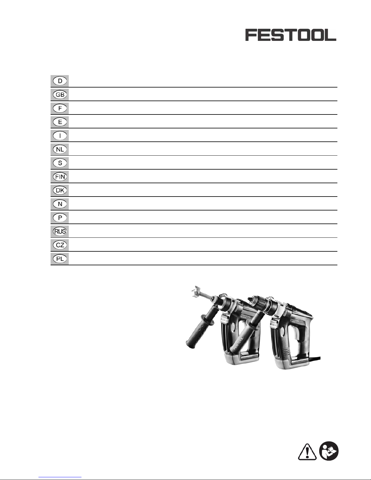
[1-1]
Bit store
[1-2]
LED light switch
[1-3]
LED lamp
[1-4]
Speed set button
[1-5]
Switch for selecting drilling/fastening or
impact drilling mode (only PD 20/4 E)
[1-6]
Gear switch
[1-7]
On/Off switch
[1-8]
Right/left switch
[1-9]
Mains power cable
[1-10]
Belt clip
[1-11]
Additional handle
Page 8

Q U A D R I L L
13
GB
a hazard, have them replaced by an authorised
after-sales service workshop.
– Always guide the cable backwards away from the
machine.
– Take care when drilling into walls as there is a
danger of rupturing concealed gas/water pipes
or cutting through power cables.
–
Only for AS/NZS:
The tool shall always be supplied via residual current device with a rated residual current of 30 mA or less.
6Operation
6.1 Switch on/off
On/off switch [1-7]
Press = ON, release = OFF
The speed of the machine depends on how far
the on/off switch is pressed in.
Speed set button[1-4]
Press once = ON, press twice or press on/off switch
= OFF
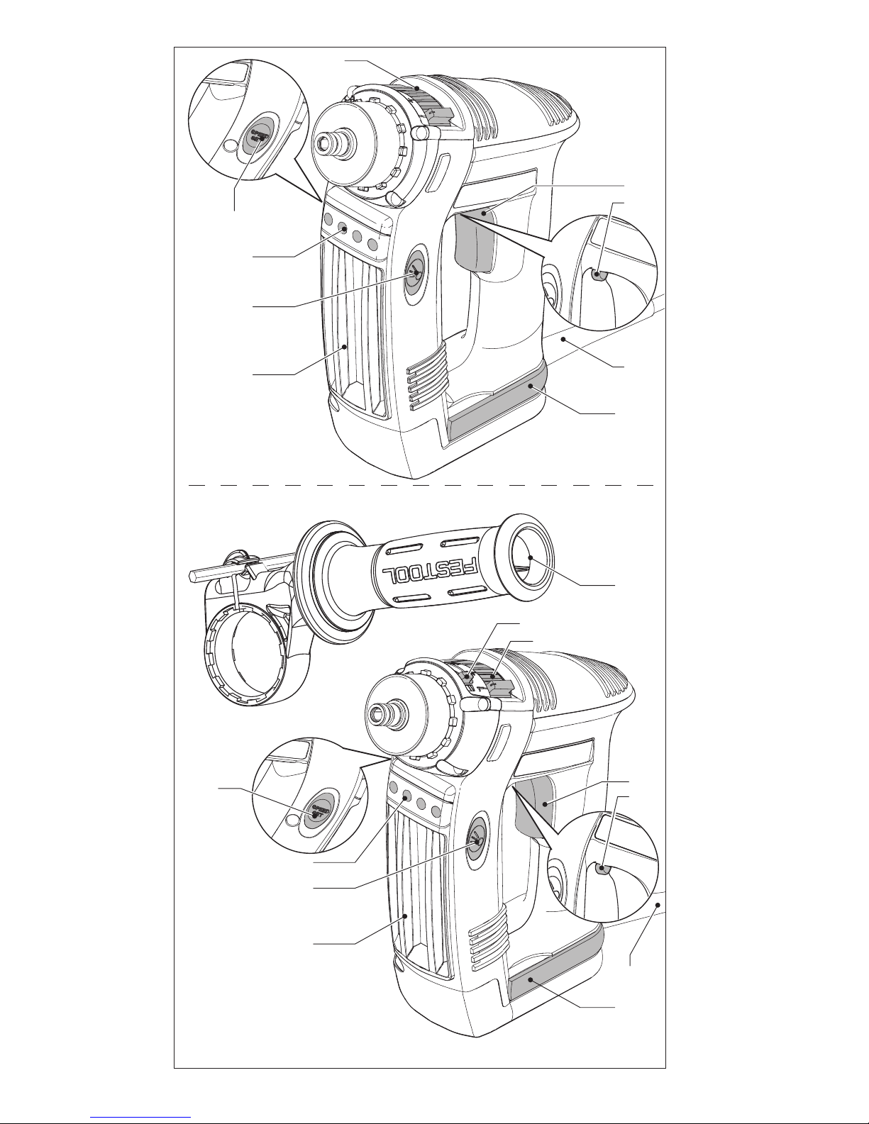
6.2 Attaching the additional handle[2]
Always use the additional handle.
Position the additional handle
[2-2]
on the extension of the gearbox housing and engage the
recesses on the additional handle in the lugs on
the housing.
Turn the handle until secured in position.
Turn the handle to adjust the position in 30° increments.
The drilling depth can be adjusted using the
depth stop
[2-1]
.
7 Settings
7.1 Changing the rotational direction[1-8]
• Switch to the left = clockwise
• Switch to the right = anticlockwise
7.2 Changing gear[1-6]
Only press the speed switch when the machine is off. Otherwise there is a danger of
damaging the gearbox.
7.3 Selecting the operating mode (only PD
20/4 E)
Fastening / Drilling
Set the selector switch
[1-5]
to the drill bit
symbol.
When fastening
, always remember to work
in 1st gear and at low speeds.
Impact drilling
Set the selector switch
[1-5]
to the hammer
symbol.
The machine was designed for impact drilling
into tiles, masonry and stone.
8 Tool holder, attachments
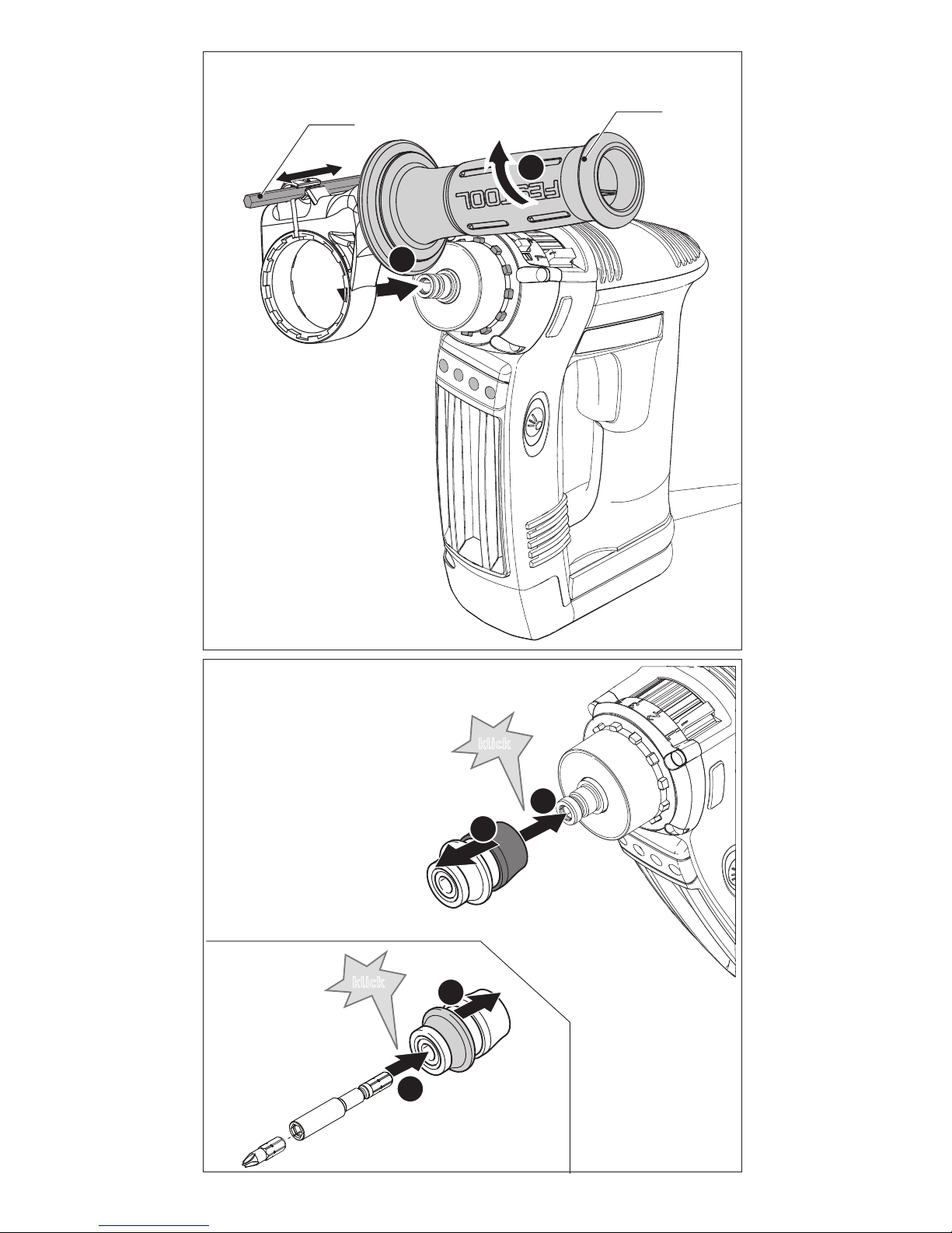
8.1 CENTROTEC tool chuck [3]
Quick change of tools with CENTROTEC shaft
Only clamp CENTROTEC tools in CENTROTEC tool chucks.
Wear gloves when replacing!
8.2 Chuck [4]
The drill chuck retains the drill or screwdriver bit.
Before initial use:
apply a coat of multi-purpose
grease to the drill spindle.
WARNING
Unauthorised voltage or frequency!
Risk of accident
The mains voltage and the frequency of the power source must correspond with the specifications on the machine's name plate.
WARNING
Risk of injury, electric shock
Always pull the mains plug out of the socket before performing any type of work on the machine!
WARNING
Risk of injury, electric shock
Always pull the mains plug out of the socket before performing any type of work on the machine!
CAUTION
Risk of injury
Clamp the tool centrally in the drill chuck!
Page 9

14
Q U A D R I L L
GB
8.3 Angle attachment [5]
The angle attachment (partly as an accessory) allows the user to drill and fasten at right angles to
the machine.
Prior to initial use:
apply some multi-purpose
grease to the drill spindle and the gearbox neck.
8.4 Depth stop [6]
The depth stop (partly as an accessory) allows the
user to insert screws to a predefined depth. You can
set the dimension by which the screw head protrudes above or is recessed below the surface of the
workpiece.
Depth setting
Turn the housing
[6-1]
to set the
desired fastening depth. Each
detent position changes the fastening depth by 0.1 mm.
Sleeve A/B must be removed before a screw can be
unscrewed.
8.5 Tool holder in the drill spindle [7]
Bits can be inserted directly into the hexagon socket holder of the drill spindle.
9 Working with the machine
Please observe all mentioned safety informations and the following rules when working:
– Only use tools designed for the specified maxi-
mum speed.
– Only sharp tools ensure efficient drilling and pre-
vent machine overload.
– Always use faultless, sharpened HSS drill bits
(HSS: High Speed Steel) when drilling into metal.
– Do not cause the machine to seize through over-
loading.
– Always switch off the machine before placing on
the nut/screw.
– Caution: when inserting long screws, there is a
risk the bit may slip from the screw head and
cause injury.
– Machine vice: clamp the workpiece securely in a
machine vice, for example, before drilling to prevent the workpiece from turning and causing accidents.
9.1 Bit depot [1-1]
Magnetic, for storing bits and bit holders.
9.2 Belt clip [1-9]
The belt clip (right/left) allows the user to attach
the machine briefly to work clothing.
9.3 Lighting
ON: Press the LED light switch
[1-3]
.
OFF: Press the LED light switch
[1-3]
again.
The light remains switched on for approx. 20 s
after the machine is disconnected from the
mains power.
9.4 Warning signals
Acoustic warning signal
An acoustic warning signal sounds and the machine switches off in the following operating states:
Visual warning signal
A visual warning signal is issued and the machine
switches off in the following operating states:
10 Service and maintenance
Customer service and repair
only
through manufacturer or service
workshops: Please find the nearest
address at:
www.festool.com/Service
Use only original Festool spare parts!
Order No. at:
www.festool.com/Service
To ensure constant air circulation, always keep the cooling air openings in
the motor housing clean and free of blockages.
Machine overloaded.
LED
[1-3]
Red - flashing
Machine has overheated.
Press the Speed set button
[1-
4]
to switch the machine to
recovery mode.
Do not place
under load
! The machine
reverts to normal operating
mode once the machine has
cooled, if the Speed set button
or on/off switch are pressed or
the machine is placed under
load.
WARNING
Risk of injury, electric shock
Always disconnect the mains plug from the
socket before performing maintenance work on
the machine!
All maintenance and repair work which requires
the motor housing to be opened must only be
carried out by an authorised service workshop.
peep peep peep
EKAT
1
2
3
5
4
Page 10

Q U A D R I L L
15
GB
11 Environment
Do not dispose of the device in household waste!
Recycle devices, accessories and packaging. Observe applicable country-specific regulations.
EU only:
European Directive 2002/96/
EC stipulates that used electric power tools must
be collected separately and disposed of at an environmentally responsible recycling centre.
Information on REACh:
www.festool.com/reach
12 EU Declaration of Conformity
We declare under sole responsibility that this product complies with all the relevant requirements in
the following Directives, standards and normative
documents:
2006/42/EC, 2004/108/EC, 2011/65/EU, EN 607451, EN 60745-2-1, EN 60745-2-2, EN 55014-1, EN
55014-2, EN 61000-3-2, EN 61000-3-3.
Festool Group GmbH & Co. KG
Wertstr. 20, D-73240 Wendlingen, Germany
Dr. Martin Zimmer
Head of Research, Development and Technical
Documentation
2013-04-20
Drill / Impact drill Serial no.
DR 18/4 E 767832, 767839,
769218, 499928
PD 20/4 E 767833, 467840,
769222, 499926
Year of CE mark: 2013
 Loading...