

Page 1

Getting the Most From the Festool
Domino Machine
Text and Photos by Jerry Work
For many woodworkers the construction of a butterfly leaf dining table like the small one
shown here is considered a rite of passage because it is very difficult to do correctly.
The table tops slide apart to reveal a self storing leaf that folds in the middle. By pulling
up on one half of the leaf both halves rise up to perfectly align with the table top both on
the flat top surface as well as along each edge. Then the two halves of the top slide together to engage the butterfly leaf in its deployed position.
Properly executed,
this operation is a
thing of beauty in
and of itself. Most
people watching a
butterfly leaf table
open for the first
time seem to be
transfixed as they
watch everything
side so effortlessly
into perfect alignment. And, watching
the leaf fold down
and store below the
table top is no less
captivating.
I often caution my
customers to be
prepared for the first
dinner party on their
new table. If the
guests see the butterfly leaf deploy, they
usually will stand around opening and
closing it time after
time just because it
is fun and interesting
to do.
Using conventional
tools and techniques
it is very difficult to
get all the pivot
points in exactly the
right places so designing and building
such a table can be
quite complex and
intimidating. But, as
we will see while we
follow the construction of the table
shown here from
start to finish, using
the innovative Festool Domino ma-
chine and the self
aligning, self squaring and self locking
features of the sliding dovetail joint, build-
Page 2
ing tables such as this one are well within
your grasp whether you are a hobbyist
just starting out or a seasoned furniture
maker with years of experience under
your belt.
The Domino machine is the key.
Also in this manual we will follow the construction of a conventional four leg with
side skirt style of table, an upright chest
with gracefully flaring legs and sliding
doors, and a unique “convertible” coffee
table that can quickly change look and
function.
All of these are easy to build by using
the Domino machine and are all within
your reach as well.
How should we describe this innovative tool?
to precisely aligning two or more components during assembly operations, to
making hidden latches, stops and door
slides, and much more.
As you progress through this manual I
think you will enjoy seeing examples of all
of these uses and the opportunity to learn
more about this truly remarkable and
unique woodworking tool.
Early in the U.S. introduction planning I
was asked by Festool USA how I
thought the machine should be described. Because I had lots of experience with loose tenon joinery using the
three dimensional sliding table on my
industrial slot mortising machine, I first
described it in those terms. At that time I
wrote that I would describe the Domino
machine as, “a portable loose tenon
jointer with great positional accuracy.”
And, as we will discover moving through
this manual, it certainly is that.
However, as I used the Domino machine
on more and different projects, it evolved
in my head to something much more than
those words could capture. The Domino
machine solves a whole range of woodworking issues from joining two pieces of
wood in all six ways one can joint two
pieces together, to handling a myriad of
wood movement problems that are always a part of building with solid woods,
The author, Jerry Work, designs
and hand crafts fine furniture in
the 1907 Masonic Temple building in historic Kerby, OR, where
visitors are always welcome.
glwork@mac.com
www.jerrywork.com
Page 3
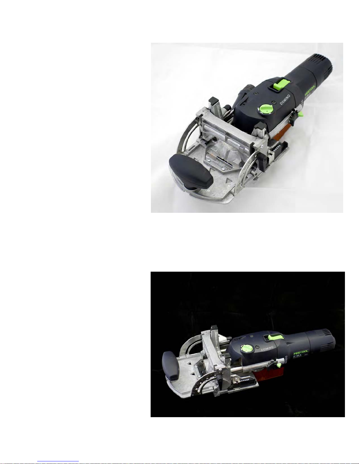
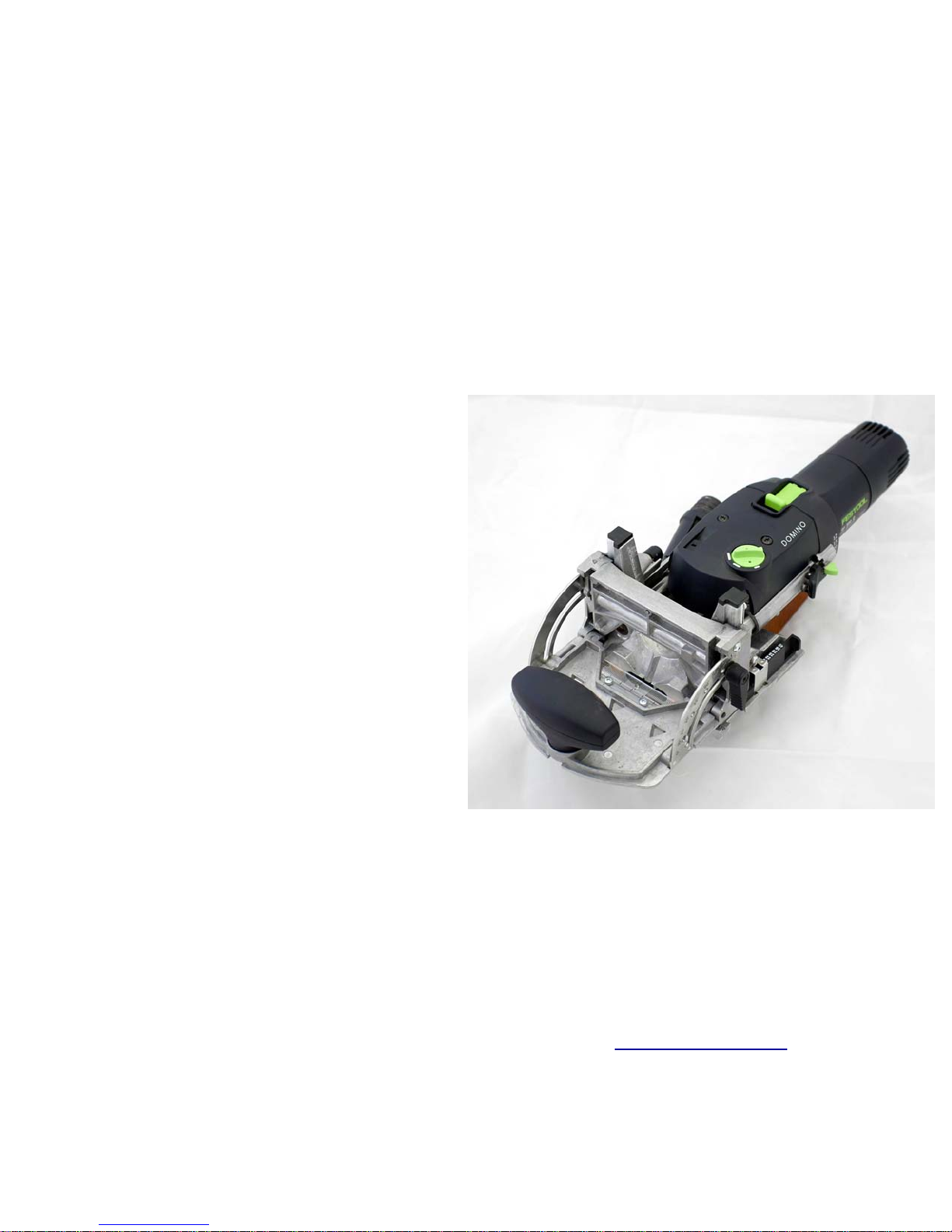
What is a Domino Machine?
Let’s begin by exploring the tool
itself. It is made up of a body
with a unique mechanism that
both rotates and oscillates a
drill-like cutter bit. The body
slides nearly effortlessly on two
hardened steel shafts built into
the fence section of the tool.
Once aligned where you want
the cut to be made, you push
the body towards the work piece
to produce an elongated slot,
most commonly called a “mortise.”
The Domino machine fence and
positioning systems allow you to
center that slot both horizontally
and vertically very accurately.
Built into the machine are adjustments for the width and the depth of the
slot. The cutters can be interchanged
easily and quickly and come in 5mm,
6mm, 8mm and 10mm diameters producing slots of those widths.
The pictures on this page show the Domino in broad view. As we come in closer
with the detailed photos on the next few
pages we will see the many precise adjustments and alignment aids.
The idea is to cut a mortise slot
into which you can insert a premade wooden tenon which Festool calls a “domino,” hence the
name of the machine.
You can make your own if you
want to, but the pre-made Festool tenons are extremely
strong, very precisely dimensioned to fit perfectly into the
mortise slot cut by the Domino
machine and they are quite
economical to buy. My recommendation is to simply use the
Festool dominos and not try to
reinvent that wheel on your own.
Page 4
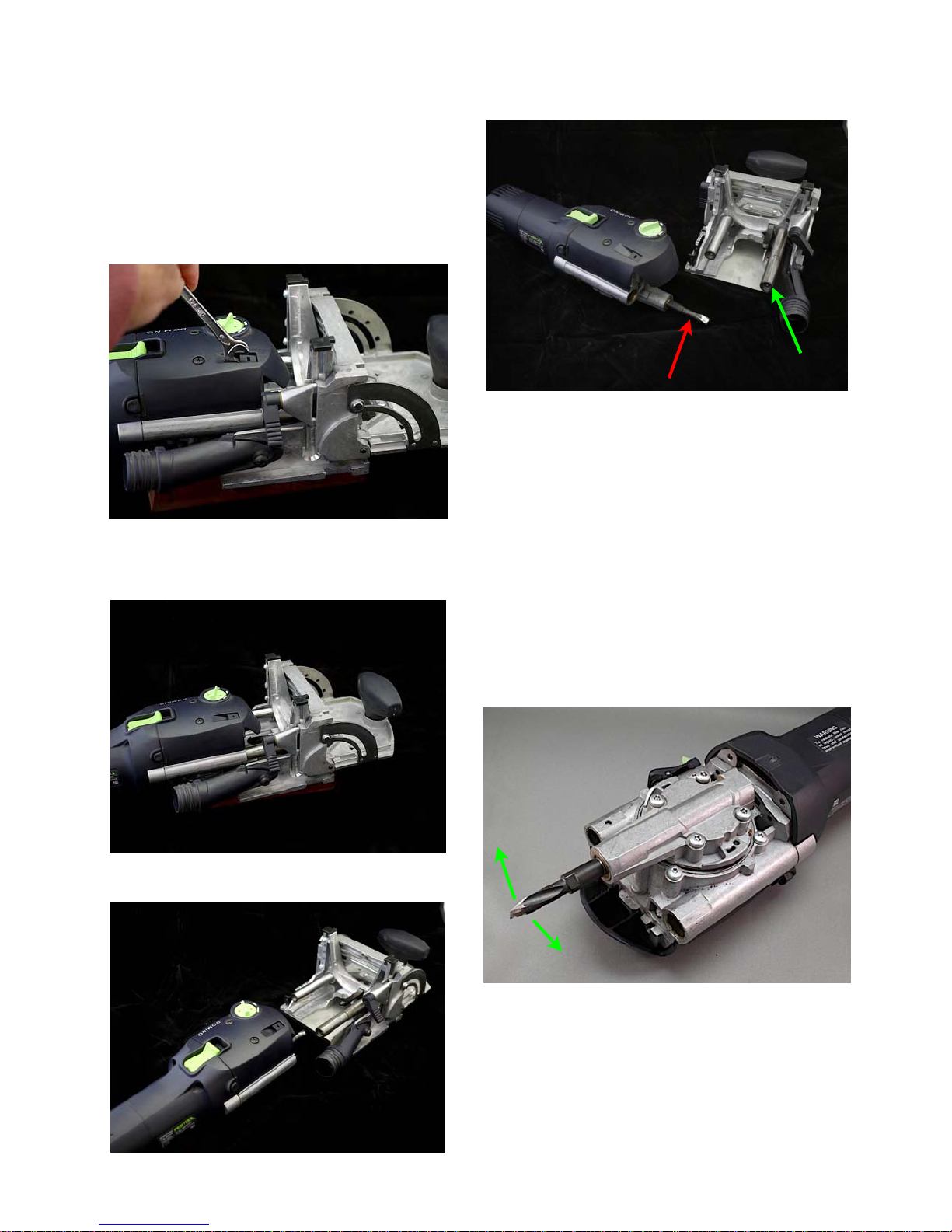
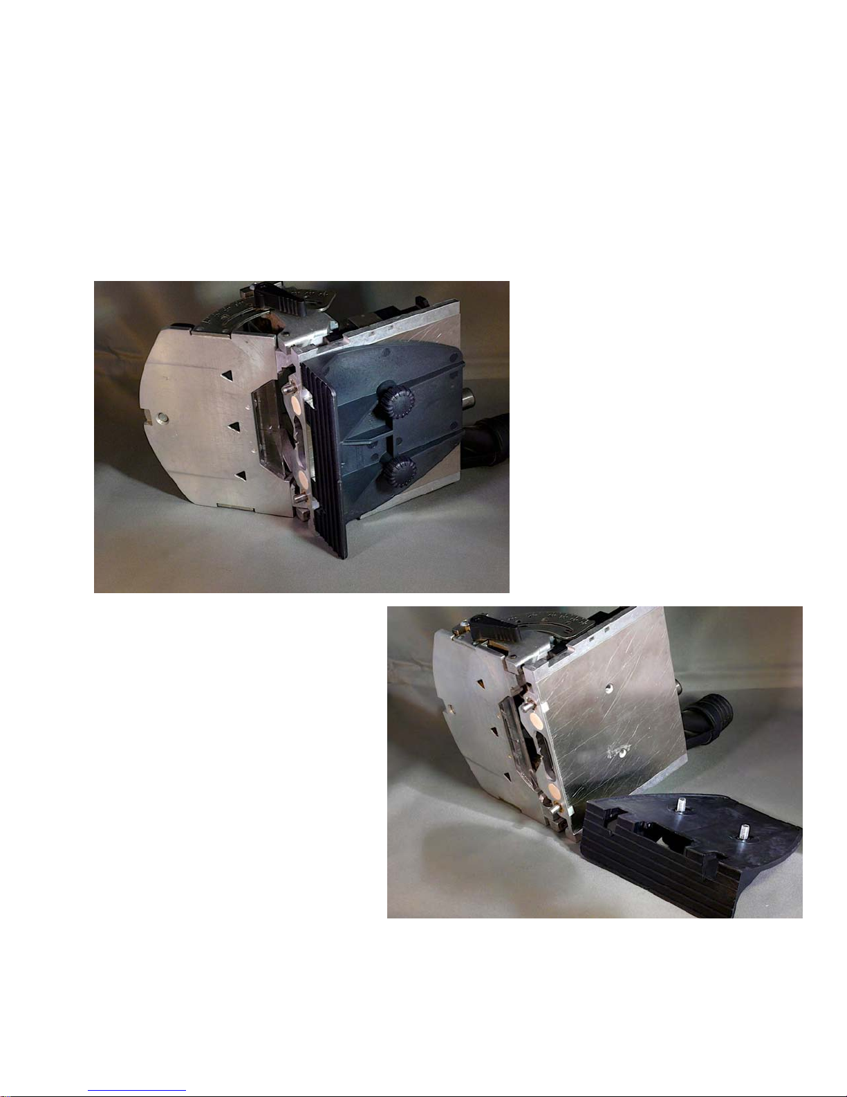
The Domino Body
This sequence of photos shows how the
body and fence can easily be separated
by simply raising the lock tab as shown
here. The wrench used to change cutters
is ideal for this. Hook the edge of the
wrench beneath the lock tab and lift it up.
The fence will start to slide off the body
as shown in the photos left and above
exposing the rotating and oscillating cutter (red arrow).
In the photo above you can see the two
hardened shafts (green arrow pointing to
the right shaft) that the body slides on as
you push the body in to cut the mortise
slot. They ensure the mortise slot will be
exactly parallel to the base of the Domino
machine, one of the keys to Domino’s
impressive accuracy.
Here is a view of the under side of the
body. The round housing held by the four
screws is gear driven to move the cutter
tip back and forth in a horizontal arc while
the cutter is also rotated to make the cut.
Page 5

The cutters can be easily changed as
they just screw onto the threaded end of
the gear-driven shaft as shown by these
photos.
comes with the set of domino tenons.
Above, the wrench is positioned on the
flats of the cutter tip. The shaft lock button is on the side of the Domino body
right where the thumb on one hand can
easily press it while you loosen or tighten
the cutter with the wrench held in the
The photo below shows the cutters with
other hand. In the photo above I moved
my thumb down so you can see the shaft
lock lever (red arrow).
The cutters are available in four different
diameters, 5, 6, 8 and 10mm. The 5mm
cutter comes standard with the machine
itself and the four cutter set shown above
their respective Domino tenons for size
comparison.
Page 6
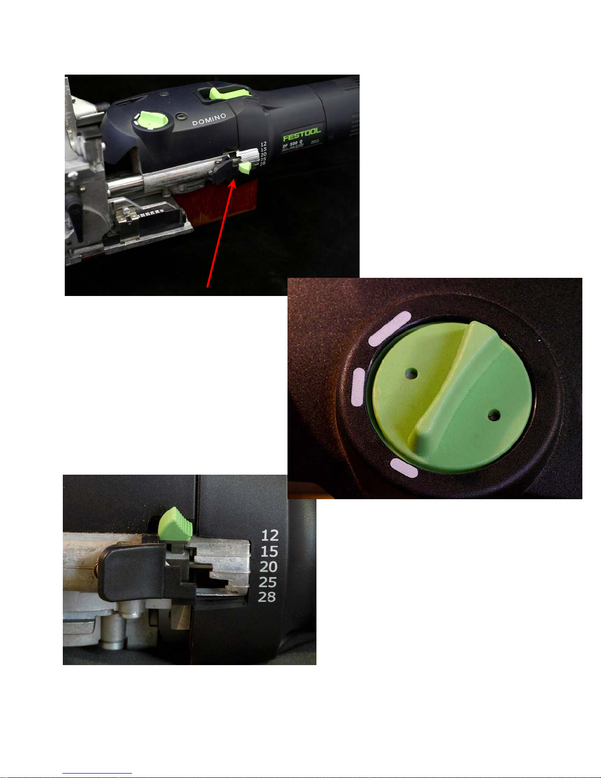
Depth of cut is controlled by a lever on
the side of the Domino body (red arrow
above and in detail below). Settings
are for depths of cut of 12, 15, 20, 25
and 28mm. This is the depth measured from the front of the fence to the
bottom of the mortise. Lift the black
safety catch and move the green depth
lever to align with the desired depth of
cut. To allow for some glue build up in
the bottom of the mortise as the tenon
shorter than the depth of the
corresponding mortise.
The top green knob turns to
set the desired width of cut.
Three settings are provided.
The narrowest width (the setting shown below) matches
the supplied domino tenon for
each domino (tenon) thickness. The 5mm thick domions are just under 19mm wide
scaling up to the just under
23mm width of the 10mm
is inserted, the actual length of the Festool supplied tenons is about 1.5mm
thick dominos.
At the minimum width of cut setting
(the way the width knob is set in this
photo) the cutter bit oscillation is
13.7mm. With a 5mm cutter bit the
overall cut mortise slot will be 13.7 + 5
= 18.7mm wide, nominally 19mm.
Move the knob to the intermediate
width of cut setting and the oscillation
increases from 13.7mm to 19.2mm
resulting in a slot 24.5mm wide for the
5mm cutter bit. The tenon still fits tightly
Page 7
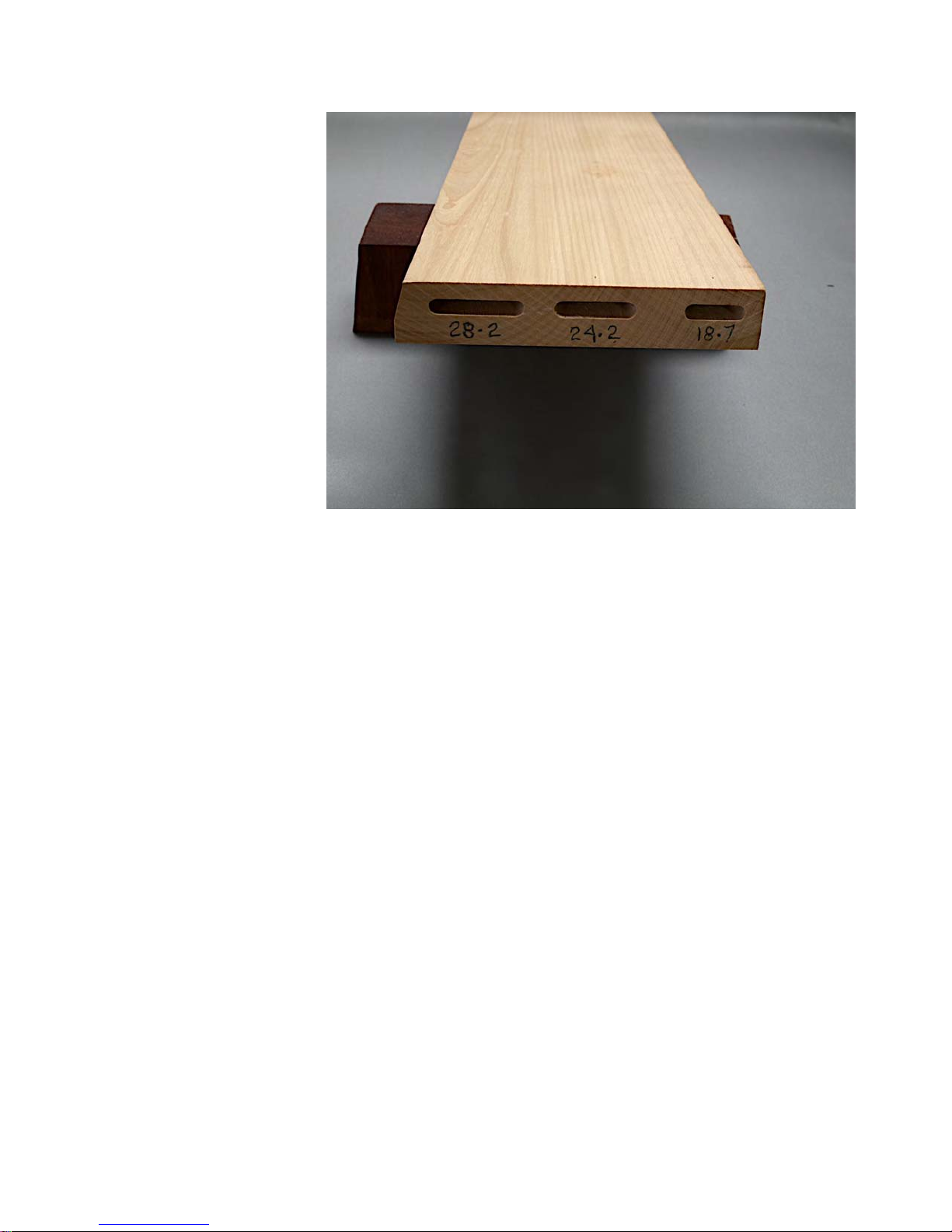
into the sides of the
mortise slot, but the
slot is longer than the
width of the tenon allowing some assembly
adjustment room side
to side. The third width
setting increases the
oscillation to 23.2mm
resulting in a 28.2mm
mortise slot which provides close to 10mm
side to side adjustment
room.
The ability to vary the
slot width is key to
many of the Domino
machine attributes. As
indicated, at the narrow
setting the domino tenon fits tightly into
the slot. At the wider settings the thickness of the domino tenon fits tightly into
the mortise slot front to back, but the
domino tenon is free to shift side to side.
We will see numerous examples of when
and where you want to use tight fitting or
over-width mortise slots as we progress
through the manual and show actual projects in process.
When you cut a tight mortise (width knob
at the narrowest setting) at the same location on two different boards, that one
M&T joint will keep the two boards
aligned as desired. Placing wider mortise
slots along the same face of one of the
two boards means the remaining domino
mortise slots can be cut with some margin for positional error while still allowing
the joint to close properly, a great advantage over dowel joints where the positional accuracy must be dead on or the
joint simply will not close up at all.
Since the majority of the strength of a
loose tenon joint is derived from the fit
and glue surface on the faces of the mortise slot and the faces of the tenon, little
strength is lost when the width of the mortise is greater than the width of the tenon.
Page 8
The Domino Fence
Now let’s look at the adjustments on the
fence part of the Domino machine. In this
photo we are looking at the back side of
the fence with the body removed. You
can see one of the two hardened steel
rods that the body slides on as it moves
the cutter in and out of the work piece
keeping the mortise slot parallel with the
base of the fence.
10mm above the centerline of the cutter.
A lock lever secures the fence at the desired height. The fence moves up and
down on machined ways so it remains
exactly parallel with the cutter at all
heights.
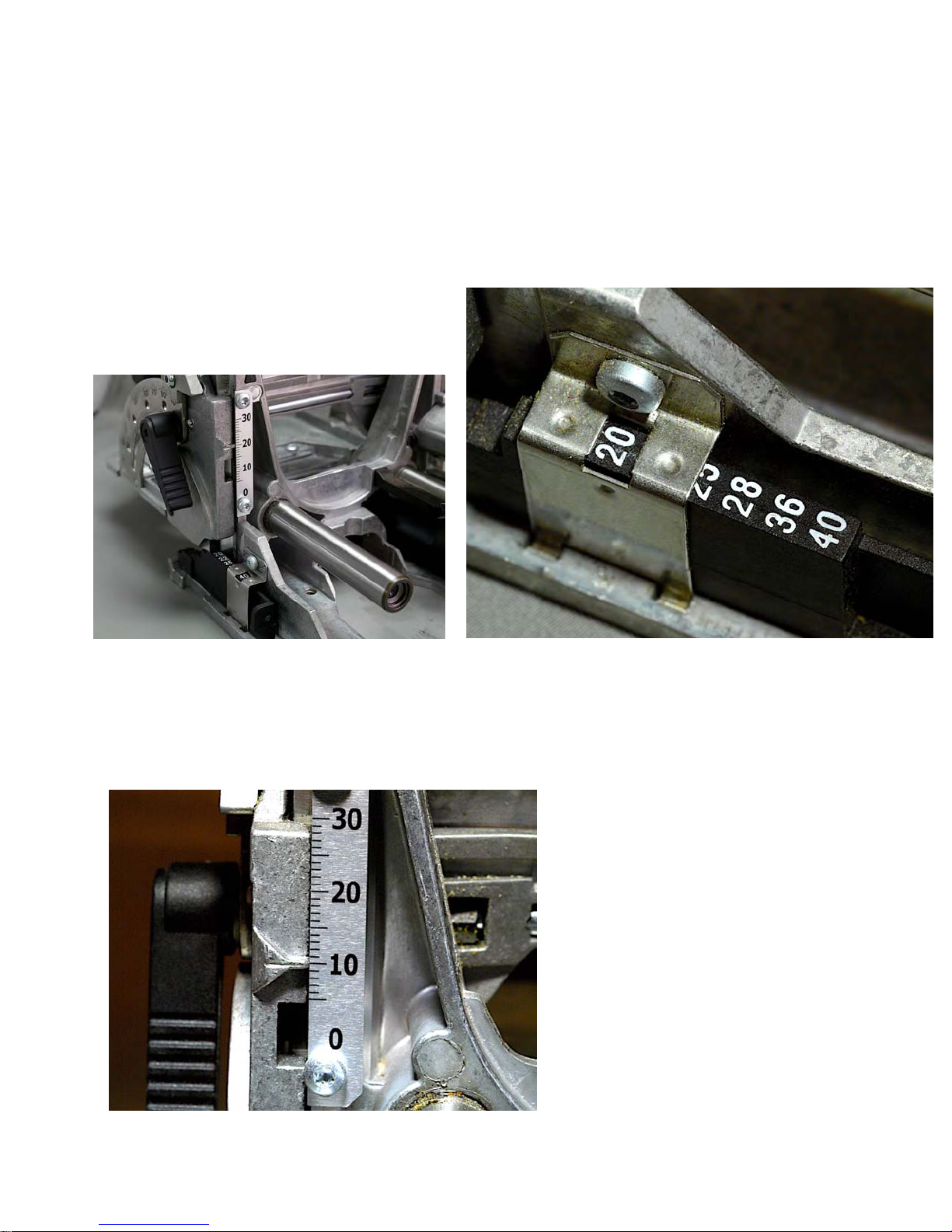
The first adjustment to consider is the
height the fence is above the horizontal
centerline of the cutter. That is shown
by a scale and pointer. In the close up
photo below the fence is set to be exactly
For rapidly setting the fence to common
heights above the horizontal centerline of
the bit, a stop block (shown in detail
above) is provided that slides back and
forth to reveal different step heights. The
fence sits on the top of a stop
block step, positioning it exactly
an indicated distance above the
horizontal centerline of the cutter.
The stop block (shown here at a
setting of 20mm) is marked in
units corresponding to the overall
thickness of the work piece for
which the cutter will be exactly
centered. In this case the stop
block is set for a 20mm thick work
piece resulting in the pointer
(photo left) indicating that the centerline of the cutter will be at
10mm.
Page 9
The stop block is marked to center the
bit on work pieces 16, 20, 22, 25, 28, 36
and 40mm thick.
You can also simply use the height
scale to set the fence any distance you
want it to be above the horizontal centerline of the bit within the range of 7mm
to 30mm.
The minimum height of 7mm ensures
that a 10mm cutter will leave a minimum
of 2mm of wall between the upper side
of the mortise slot and the upper side of
the work piece so you don’t inadvertently
drive the cutter into the bottom side of the
fence.
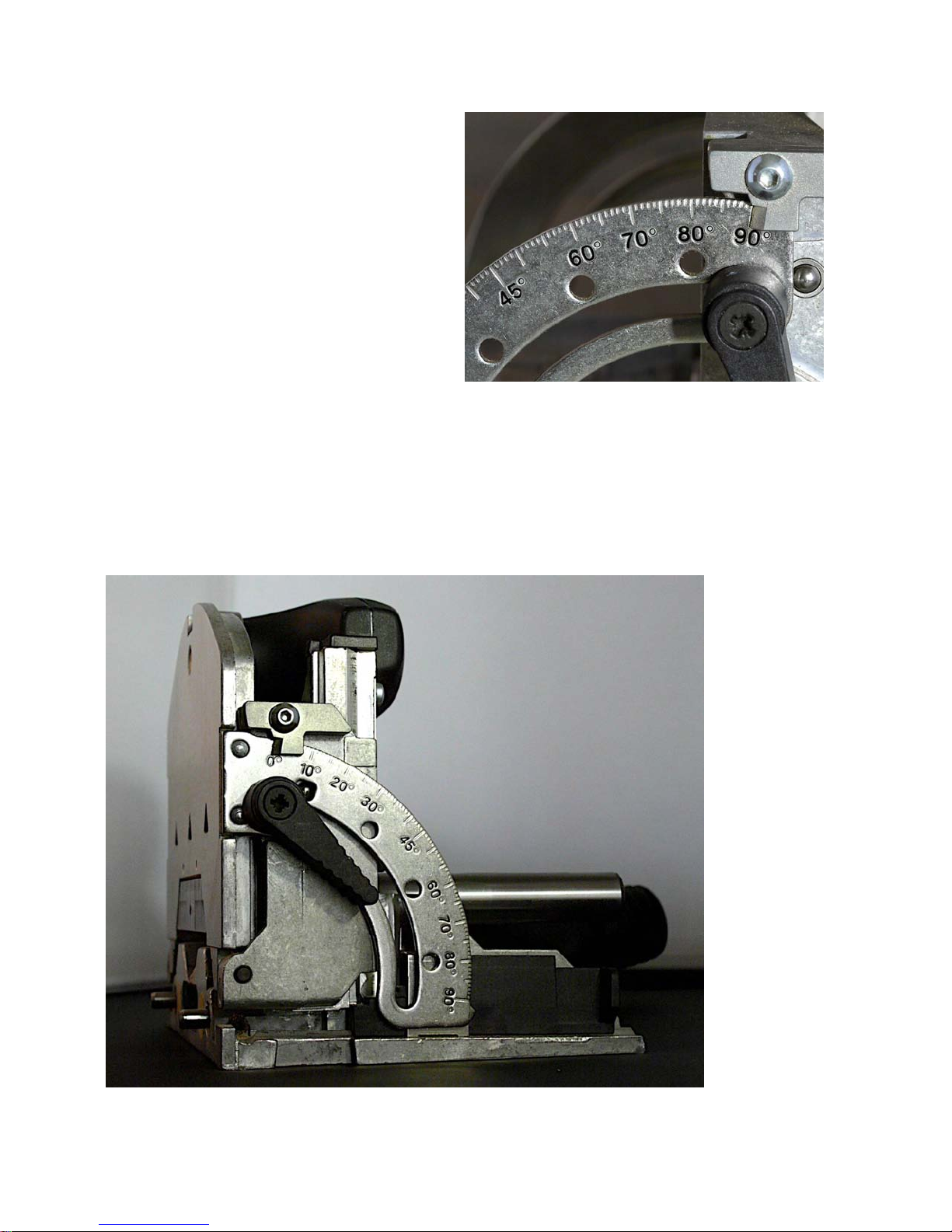
The fence also rotates from 90 degrees
angle relative to the edge of the work
piece (meaning the fence is parallel with
the cutter) to zero degrees relative to the
edge of the work piece (meaning the cutter is moving perpendicular to the fence
the way it is shown in the photo left).
Ball detent stops are also provided for
common intermediate
settings, or
you can simply set the
angle with the
protractor
scale and
pointer. The
pointer is adjustable so
you can calibrate the angles to be
dead on.
Now let’s look
at the variety
of alignment
marks to help
you place the
mortise slots
exactly where
you want
them.
Page 10
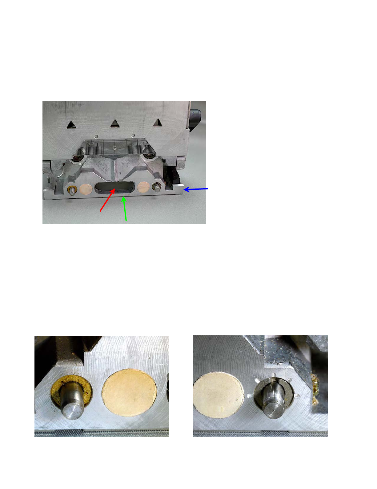
This first photo is looking at the front of
the Domino fence with the fence piece
raised to the zero degree angle for clarity
of view. The slot in the center towards
the bottom (red arrow) is where the cutter
emerges when the body is pushed towards the work piece to make the mortise
cut. The cutter centerline is 10mm up
from the base of the fence assembly
(green arrow above).
Two alignment pins are spring loaded and
are set 74mm apart so each is 37mm
from the centerline of the cutter.
The right and left spring loaded alignment
pins are shown in detail below. The right
pin is mounted in an eccentric with a
screwdriver slot by which you can turn
the eccentric to bring the two pins into
exact alignment the same distance
from the vertical centerline of the
cutter. The left pin is fixed in position 37mm from the vertical centerline of the cutter and 24mm from the
outside of the pin to the outside
edge of the fixed portion (base) of
the fence (blue arrow).
The pins are 5mm in diameter so
the base is machined to be 132mm
wide or 66mm from outside edge to
vertical center of cutter. All of these
measurements are very useful to
keep in mind as they each can play
a role in helping you precisely position the center of the Domino mor-
tise slots.
When you first get your machine, make
sure the adjustable fence height pointer is
exactly on 10mm when the fence is on
the stop block marked 20mm, the angle
pointer is exactly on mark, and the distance between the two spring loaded pins
is 74mm. Adjust the right pin shown below if necessary.
Page 11
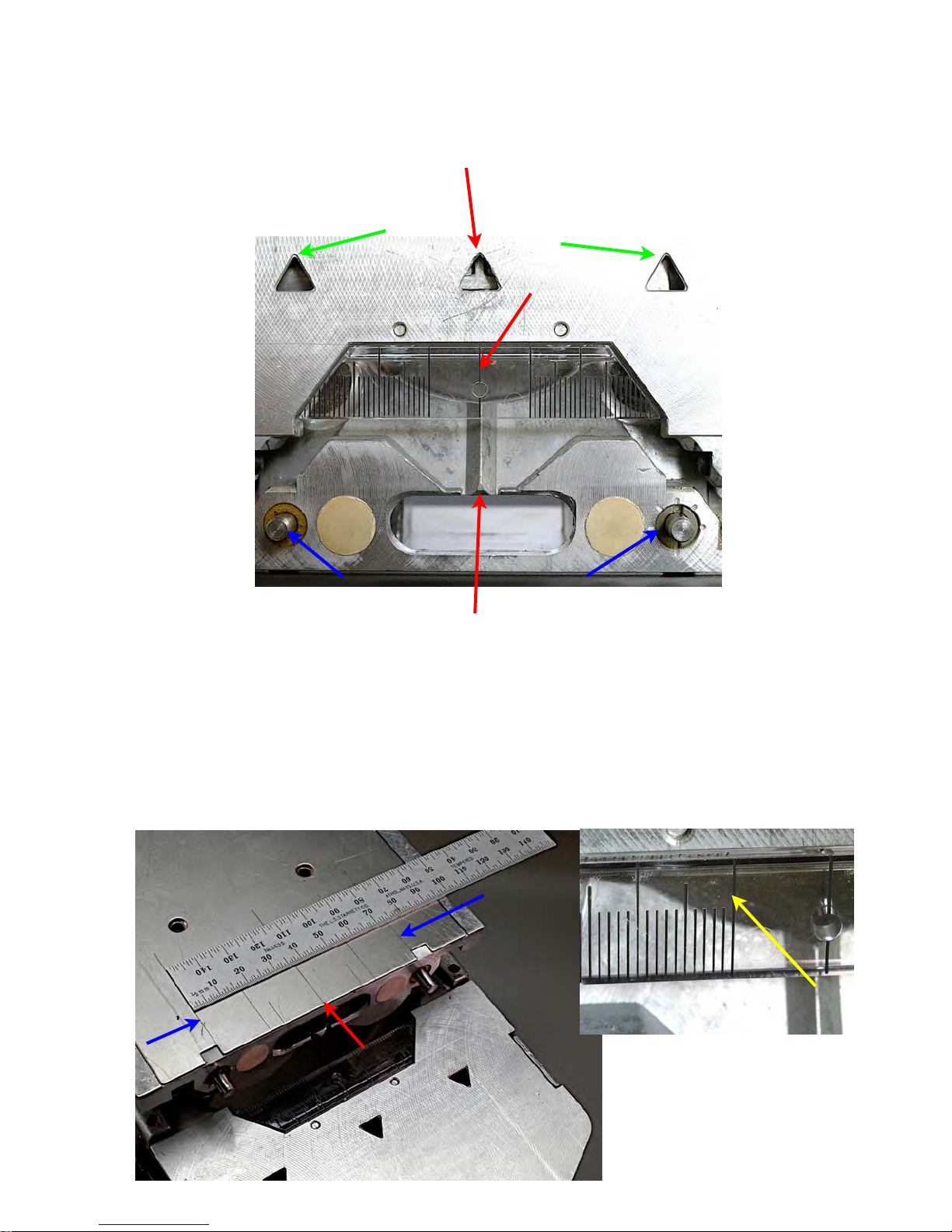
The vertical centerline of the cutter is also
marked in several other ways (red arrows) as well: by the “V” cast into the
fence base, by the line scribed on the
clear plastic
reference
scale attached
to the moving
portion of the
fence (note
the hole in the
plastic denoting center),
and the point
of the triangle
cast into the
moving portion
of the fence.
The outer two
triangles
(green arrows)
cast into the
moving portion of the fence have points
that are exactly 74mm apart, the same
as, and aligned with, the inside edges of
the spring loaded alignment pins (blue
arrows).
There is yet one further set of marks denoting the vertical centerline of the cutter.
These are scribed on the bottom of the
base of the fence (the fixed portion). I
placed a rule on the inverted base of the
fence for the bottom left photo so you can
see the centerline of the cutter lined up
with 37mm
on the rule.
The left end
lines up
with the
mark for
the inside
of the left
spring
loaded
alignment
pin while
the mark
denoting
the inside
of the right
alignment
pin is at
74mm.
5mm beyond the left end of the rule and
the 74mm mark are lines denoting the
outside edges of the alignment pins.
Two additional sets of scribe lines are set
15mm from the vertical centerline of the
bit (the shorter lines) and 20mm from the
bit center (the longer lines).
The photos above show
the clear plastic alignment
scale that tilts with the
Page 12
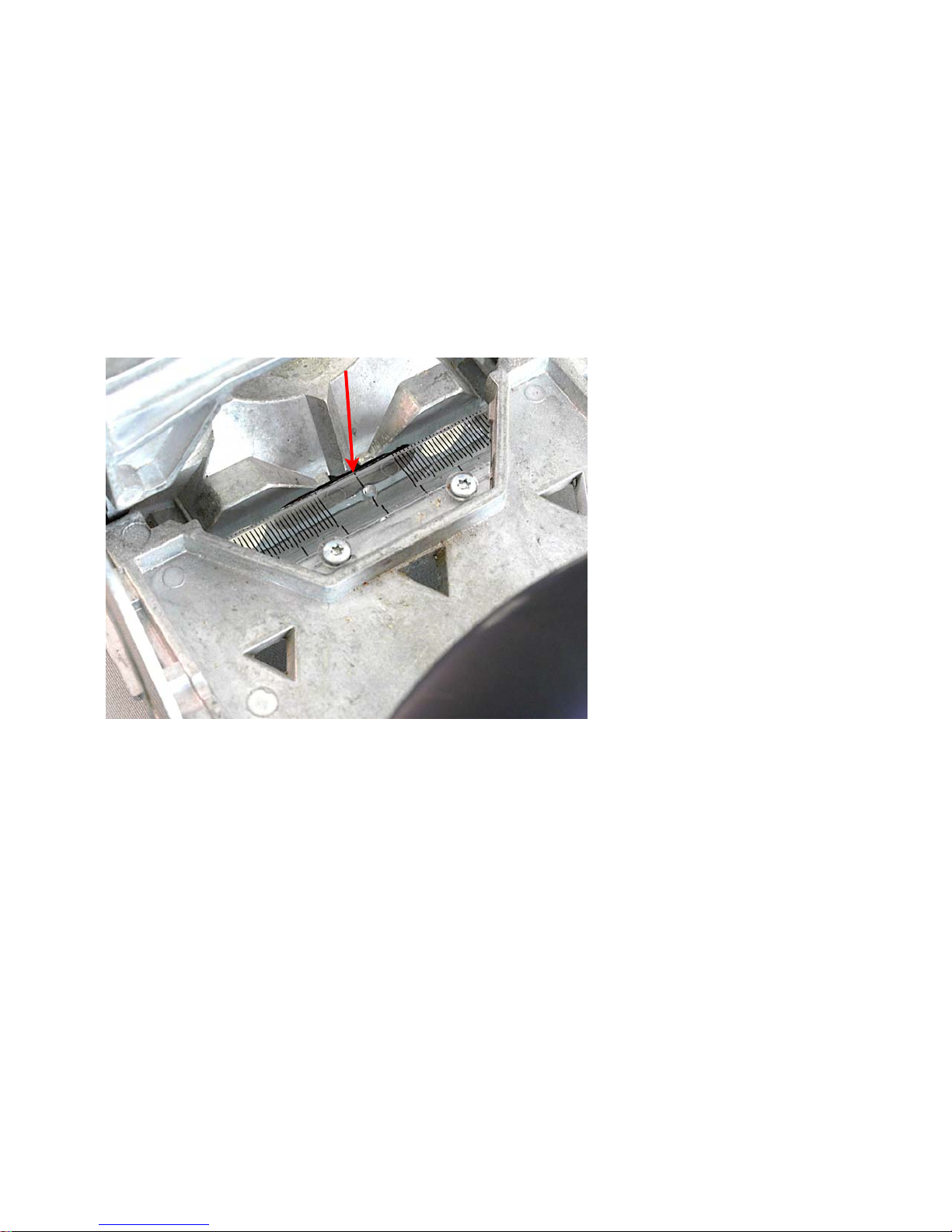
moving portion of the fence. As we saw
earlier, the center scribe line with the circle cut through it is the horizontal center
of the bit oscillation movement and hence
is the side to side center of any mortise
slot cut with any bit. Long scribe lines are
10mm increments (yellow arrow) while
the shorter lines are 1mm and 5mm increments on this clear plastic guide.
Here is a picture of the guide taken from
above the fence when it is lowered to the
horizontal position parallel with the bit oscillation. In use, it is quite visible and I
am constantly impressed by just how
close I can set the Domino mortise slot
with just this visual reference.
Once you start using the Domino you will
quickly learn to trust the marks and, so
long as you lay out your mortise slots
around centerline measurements, you
can achieve great accuracy and also do
all kinds of offsets using just your layout
mark and these several methods of aligning the Domino.
The spring loaded pins are especially fast
and accurate. By hooking one of the pins
over an end or edge of your work piece,
you will place a mortise slot centered ex-
actly 37mm from that edge no matter
what size cutter you use or what slot
width setting you choose.
Take the case of an end to edge joint
such as creating a 90 degree joint which
properly lines up the outside
edge of both pieces. Set
the fence height to place
the mortise slot where you
want it on the edge and end
of the work pieces, set the
depth of cut you want and
set the slot width to the narrowest mark (shortest white
icon of the three surrounding the green round width
adjustment knob). Hook the
alignment pin over the end
of one piece and make the
mortise cut in that edge.
Next hook the pin over the
edge of the mating piece
and make the cut into that
end. Put the Domino tenon
in place and the edges of the joint will be
perfectly aligned with no layout marking
on your part at all.
It is that easy!
Before we move on to look at all six ways
that two boards can be joined and see
how these various alignment marks and
pins are used to precisely position your
M&T Domino joints, there are three more
positioning aids we need to examine. All
come standard with the Domino Set (574-
283). If you want just the machine itself
with only a 5mm bit, that is item number
574-258.
Page 13
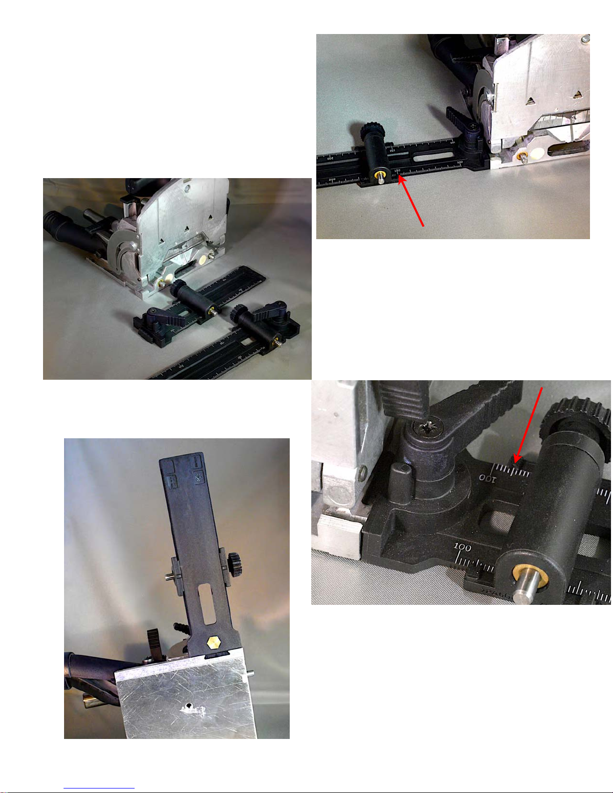
The first is a two part fence extender.
One part attaches to each side of the
Domino fence and each features a movable spring loaded reference pin and numeric scale. They attach by a clever
dovetail machined into each side of the
In the photo above the inside edge of
the spring loaded pin is set to be 150mm
away from the horizontal center of the
mortise slot. The red arrows show the
alignment scale and pointer.
In the close-up below the pin is set so it
would register the work piece to position
Domino base as shown in the photo below taken from the bottom of the base.
the mortise slot 105mm away from the
edge of the work piece that rests against
the stop pin.
Page 14
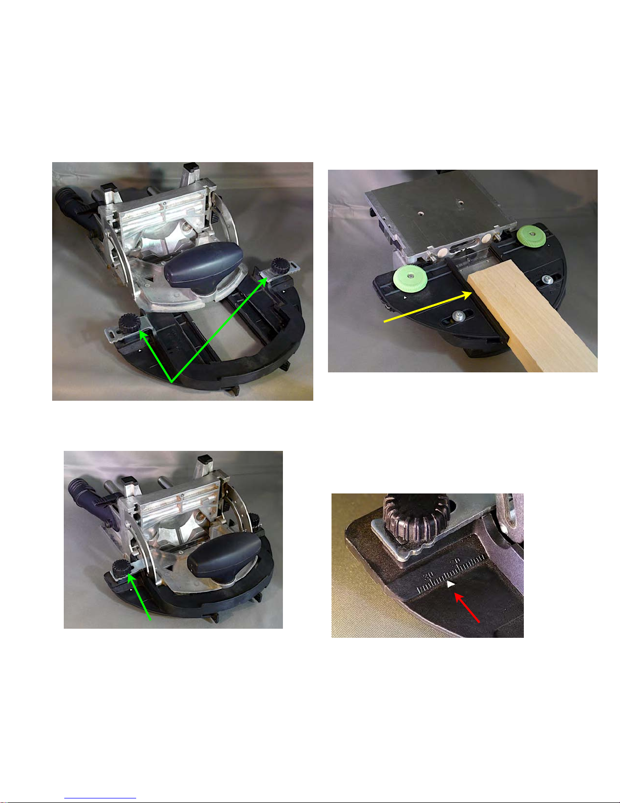
The second very useful positioning ac-
cessory is a saddle fence that attaches
to the bottom of the moving portion of the
fence. Here the Domino body is removed
from the fence to make it easier to see.
the in-out motion of the cutter (yellow arrow). They capture and hold the edges of
the work piece making it easy to cut mortises in the end grain. The green knobs
secure the fences in the desired position,
The saddle fence slides onto the fence
and locks in place via the two black
knobs and metal fingers (green arrow).
The photo above right shows the bottom
of the saddle fence. It features two movable fence elements that run parallel with
and on top (detail below), is a scale that
indicates how far away those fence sides
are from the vertical center of the mortise
slot.
Want to cut a 10mm mortise in the center
of the end of a 20mm x 50mm work
piece? Set the fence to 10mm high and
set the two sides of the saddle fence to
25mm as shown above. The resulting
mortise will be exactly centered in the
Page 15
end grain no matter which cutter you use
or which width setting you select. Neat!
The third accessory is for stabilizing the
Domino machine when used upright cutting into the face of a work piece registered off of an edge. It is an auxiliary
fence that screws to the bottom of the
Now that we are familiar with the
Domino machine and the variety
of ways to accurately register the
location of the mortise slot, let’s
take a look at the six ways you
can join two pieces of wood together.
Then we will move on
to several build-along
projects that show the
amazing versatility of
this innovative wood
working tool.
moving portion of the Domino fence.
This photo shows it installed with the
fence set to 45 degrees. Right is a
photo showing the auxiliary fence
before it is mounted to the bottom of
the moving portion of the Domino
fence, shown here set at zero degrees (perpendicular to the movement of the cutter.)
Page 16
There are only six ways you
can join two pieces of wood
together.
I will refer to the surfaces of a board
as the faces (the wide flat top and
bottom of the board), the edges (the
sides of the board) and the ends.
Boards can be joined:
1) edge-to-edge
2) face-to-face
3) end-to-end
4) edge-to-face
5) end-to-face
6) end-to-edge
Do that on both boards. Since the spring
loaded pins set the horizontal mortise
center and the fence sets the vertical
mortise slot center, the ends and the
faces of the two boards will be perfectly
aligned. In the photo above you can see
that I mark the end aligned with the
spring loaded pin with an “X” mark. That
mortise is centered 34mm in from the
edge.
Edge-to-edge is a common op-
eration any time you need a
board wider than the stock you
have on hand. We usually call
that a “glue up” or a “panel
joint.”
Reinforcing and properly aligning this edge-to-edge joint is
easy, very fast and very precise
with the Domino machine. Set
the slot width to narrow, the
fence to 90 degrees and the
fence height to half the work
piece edge thickness. Hook the
pin over one end of each piece
to be joined while pressing the
fence down on the face of what
is to be the top or good surface
of the glue up. Turn on the Domino machine and push the body towards the
work piece until it bottoms out at the desired depth of cut to machine the mortise
slot.
I suggest you always work with the
fence on the top or “good” surface of
your work pieces so those faces will
align even if the two work pieces are
not exactly the same thickness.
Page 17

Add additional Domino mortises along the
edges of each board using either of two
methods. First you can use the excellent
two part fence extender (called a “side
stop” in Festool literature) we saw earlier.
Set the pin spacing to match the desired
mortise to mortise spacing. By hooking
the alignment pin in the edge of the mortise you just cut, the next mortise will be
spaced over by that amount. Progress
across both board with the same settings
and the mortises will all align perfectly.
You also can align by just marking the
desired locations with a pencil line across
both boards. Leave the slot width set to
narrow and cut mortises with the bit center mark aligned with each of your pencil
lines on one of the two boards to be
joined. Reset the slot width to the wider
slot setting and cut the remaining mortise
slots in the second board (shown in the
photo at the top of the previous page).
Since the first mortise slot in each board
is the same width as the Domino tenon,
that one M&T joint will align the two
boards end to end. The slightly wider
mortise slots you cut for the remaining
mortises in the second board will offset
any minor misalignment that might be
present, allowing the two edges of the
boards to come tightly together with the
faces perfectly aligned.
The Domino mortise slot to Domino tenon
fit is much tighter than is the case with a
biscuit jointer so the face to face alignment is much better. The Domino tenons
are also a lot stronger, set deeper and
provide more glue surface area than a
biscuit so a Domino reinforced edge-toedge joint is superior in every way to an
equivalent biscuit edge-to-edge joint in
my experience.
While you can cut these Domino mortise
slots at any height down the edge from
the face of the boards, conventional “wisdom” would have you place them in the
middle of the two work pieces to be
joined. Usually the recommendation is
to use a tenon one third the thickness of
the work pieces to be joined thereby leaving an edge to slot width the same as the
tenon width.
In working with Dominos I find I prefer to
use a Domino that is half, rather than one
third, the thickness of the work pieces to
be joined. The Domino tenons do not
swell up the way biscuits can and the
grain runs the length of the Domino tenon. Since the Domino penetrates into
the edge of the work piece a relatively
long way (anywhere from 15 to 25mm
depending on the tenon length you use,)
the bending moment is spread over
enough distance that even on a stressed
joint the relatively thinner wall provides
plenty of support.
Now let’s look at the case of a common
end-to-edge joint, such as you find in rail
and stile work.
Because it is so easy to calculate dimensions in my head this way, I commonly
use rail and stile components that are
50mm wide by 20mm thick and panel
slots are 10mm wide by 10mm deep and
centered on the 20mm thick work piece
edges or ends.
A Domino mortise and tenon centered on
the 20mm thickness of my work pieces
matches these standards perfectly. And,
I can reinforce the glued up 10mm thick
panels by using a 5mm centered Domino
mortise and tenon.
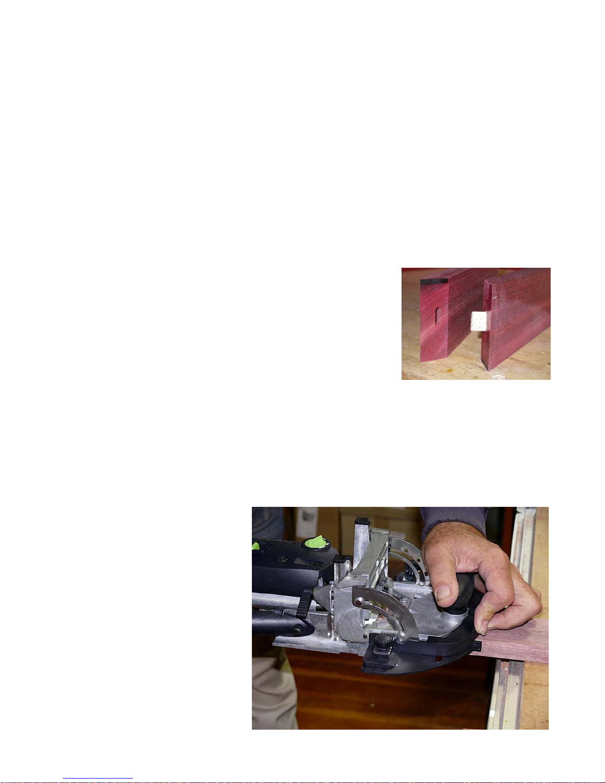
Page 18
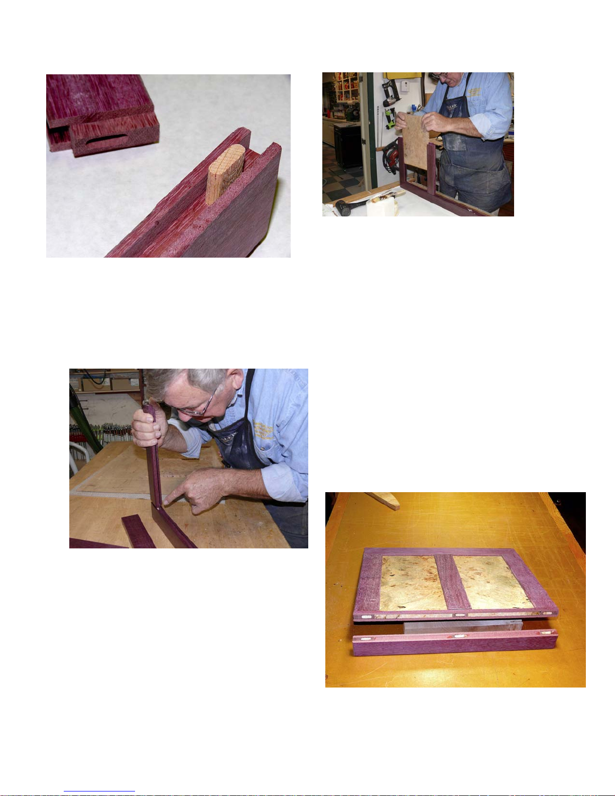
In the example shown on this page the
R&S components are Purple Heart while
the panels are Maple Burl.
If the joint is a stressed joint, such as the
corners of a door, then I like to put an
well. And, by having glue on both sides
of the trapped narrow 1mm tongue wall,
the joint is incredibly strong.
In the photo left my finger points to the
joint going together and above is a photo
of a panel being inserted into a three
panel R&S assembly that was made this
way.
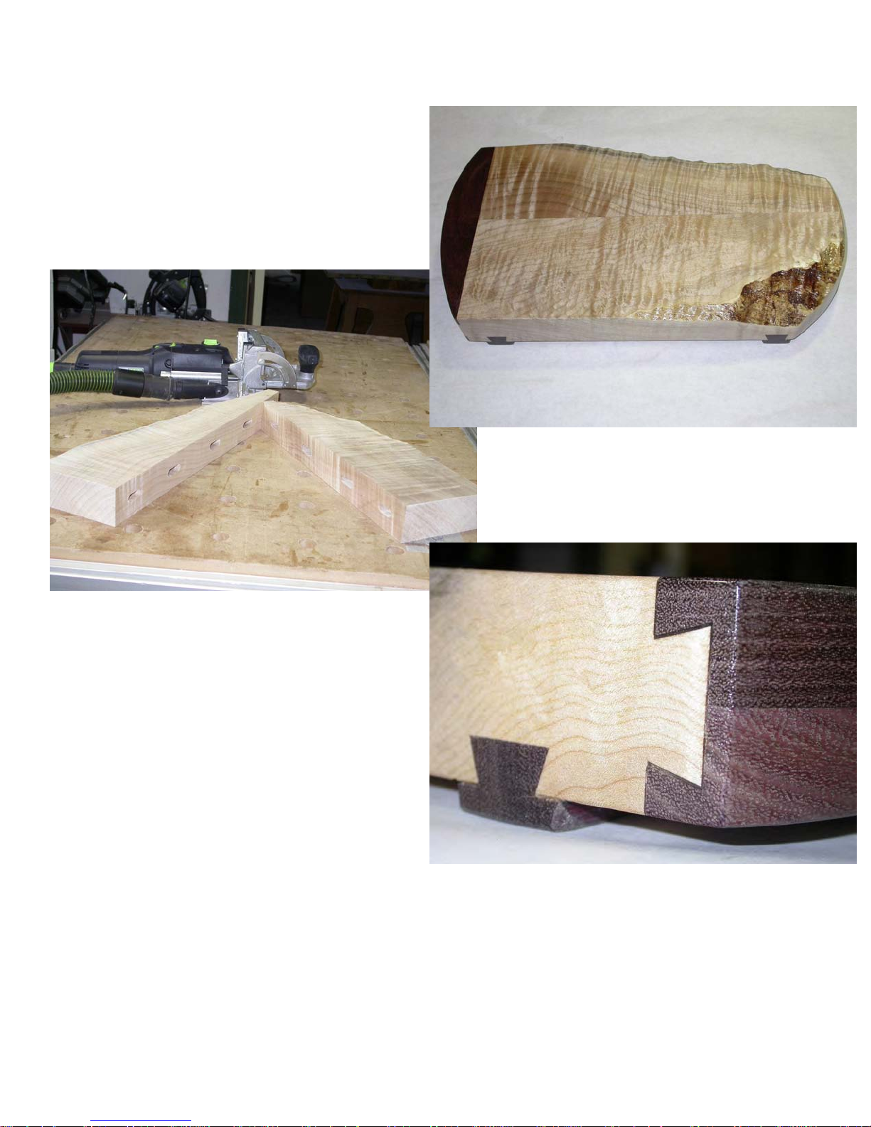
Below is a cut away of a door done
this way to show how the precise positioning the Domino machine provides can quickly and easily cut what
many would consider a most difficult
joint - three 8mm M&Ts cut inside
three 10mm tongue and groove joints,
all perfectly aligned!
8mm Domino M&T inside the 10 x 10mm
tongue and groove cut into the rail and
stile pieces as shown above. The 10mm
tongue is cut into the rail piece and the 10
x 10mm groove cut into the stile piece.
The 8mm Domino mortise is cut into the
middle of the groove and the middle of
the tongue (top photo).
The Domino M&T not only strengthens
this joint, it also automatically aligns it as
Page 19
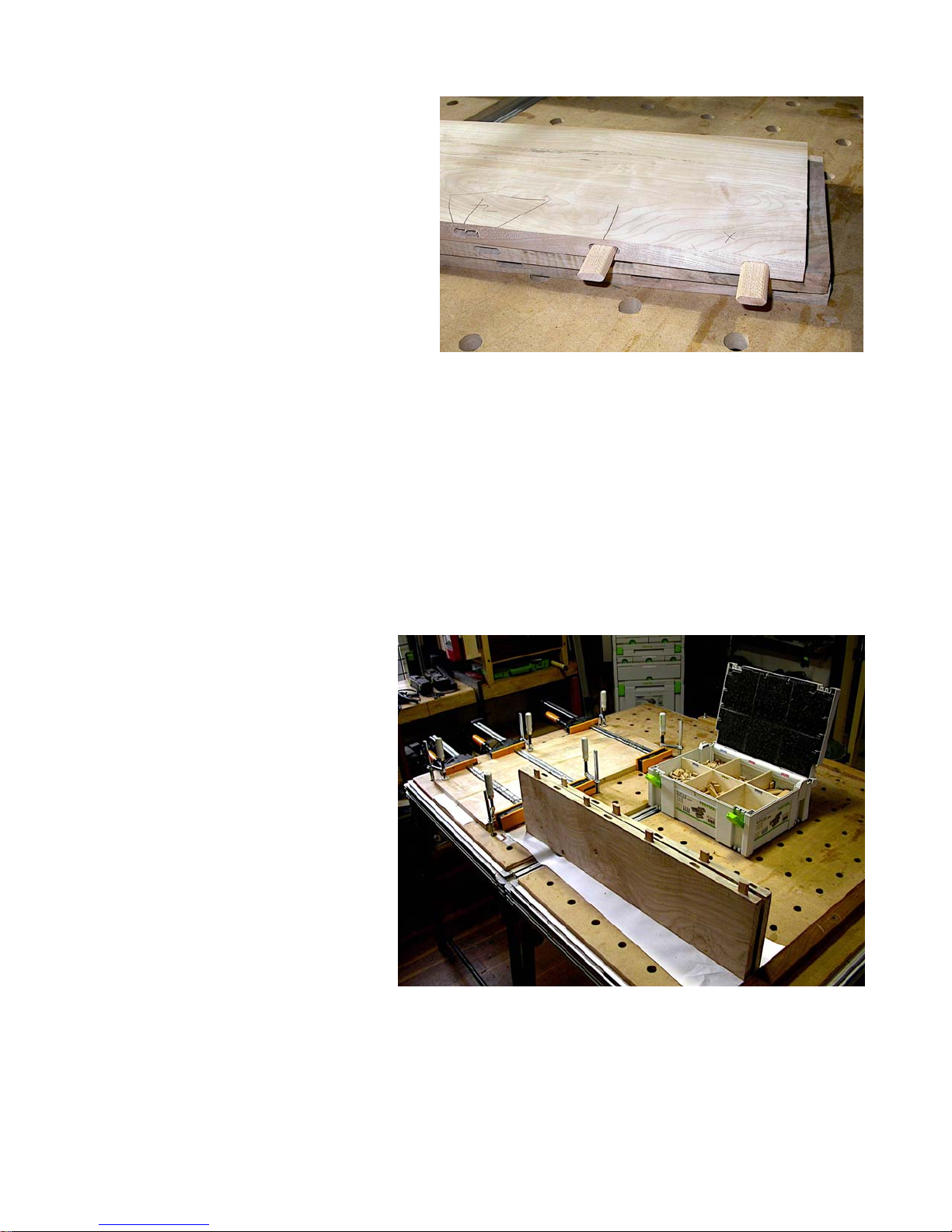
Just for fun here is an edge-to-edge joint
used to join two thick pieces of maple
together to make a fancy countertop
chopping block.
Waterproof glue and four 10mm x 50mm
Domino tenons make sure this chopping
The Domino machine makes a
fast, secure & hidden joint without that fuss.
block will never separate. The waney
edges add interest while the large
breadboard end dovetailed to the body
prevents any bowing or warping.
The dovetailed feet keep the bottom off
the countertop.
I would not consider making this piece
using biscuits as I would be concerned
about joint strength. Over the life of this
piece it will be hit with everything from a
meat cleaver to a tenderizing hammer
and it will be in and out of cleaning water
constantly.
BD (before Domino, grin) the only way I
could do this was to either use a spline or
a sliding dovetail to hold the two pieces
together.
Now back to the edge-to-edge joints....
One tenon centered on the edge of each
work piece is usually more than strong
enough given the strength of modern
Page 20
glues. If your application demands exceptional strength and the work pieces
are more than 3.5 x the thickness of the
tenon you intend to use, I suggest setting
two tenons, each centered the tenon
thickness down from each face if the two
work pieces are exactly the same thickness. (For exceptionally stressed joints
in thick material that is at least 5x the
thickness of the tenon, set two tenons
centered 1.5x the tenon thickness down
from each face).
If the work pieces are not the same thickness, put the first tenon centered the tenon thickness down from the top or
“good” face and the other tenon down far
enough to be centered about the tenon
thickness above the bottom of the thinnest of the two work pieces.
auxiliary spring loaded pins to position
the Domino mortise slot(s).
If your work pieces are exactly the same
width, you can work from both edges. If
they are not, register all cuts from the
same edge so that one edge will be
properly aligned even if the other edge is
not.
A variation on an end-to-end joint is
strengthening a mitered end joint like the
one shown here cut in African Blood
Wood (sometimes called
“Sealing Wax
Wood” because of the
rich, red natural color).
Make all of the Domino mortise cuts with
the fence held firmly to the top or “good”
face of each work piece. That way the
good faces will be properly aligned and
the tenons will fit together nicely to produce superior joint strength to what you
would have if you used just one tenon
centered on the edges.
End-to-end joints.
For these, mount the saddle
fence if your work pieces are
each less than 70mm wide.
Each saddle fence can be positioned 35mm away from the
horizontal mortise center thus
accommodating up to 70mm
material.
If the work pieces are more
than 70mm wide then use either
the built in spring loaded alignment pins hooked over one
edge to align the two ends and/
or mount the two wings with the
The ability to
swing the
fence over a
90 degree arc range is really handy for
this cut.
Match the angle to the mortise angle, in
this case 45 degrees. Set the depth of
cut and the height of the fence to be sure
you do not cut the Domino mortise
Page 21
through to the good side of your work
pieces. Usually that will mean placing the
mortise below the joint center as shown
on the previous page and using a short
tenon. This is where the 12mm cut depth
setting is really handy.
Edge-to-face joints are common when
you want to mount one piece of wood
perpendicular to another like putting a
fixed shelf between two sides of a chest.
This is simple and easy to do remembering that the bit center is 10mm above the
base of the Domino machine. A board
clamped across the side pieces 10mm
back from your desired centerline will position the bit to cut the mortise on the
sides to wind up centered on a 20mm
shelf.
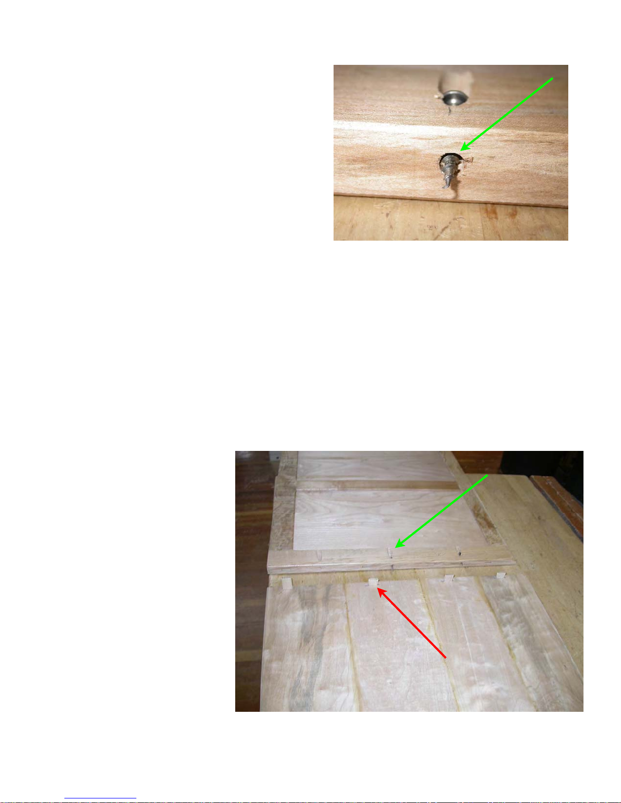
Here I am getting ready to do something
similar, but with a significant twist.
You may need even more pocket
hole clearance for some woods.
one piece aligned with the face of the
other, I am using four Domino M&Ts
without glue to hold the alignment (red
arrow), and pocket hole screws with
elongated screw holes (green arrow) to
actually hold the two pieces tightly together while still allowing one to slide
enough relative to the other....a very
handy trick to keep in mind.
While it may be hard to see in these small
photos, one of these work pieces is a
solid wood glue up (the bottom piece in
the lower photo) with grain
running up and down while
the other is a rail and stile
with the stile grain running
across the wide grain of the
glued up panel. We will
see why this configuration
is needed when we get to
the pedestal desk buildalong project a bit later.
But, given the long grain to
cross grain construction,
we certainly cannot glue
this joint or the expansion/
contraction of the glued up
panel would fracture the
glue joint in a year or less.
One final note on joining two pieces of
wood. Where even more strength is
needed than you think would be supplied
To avoid this problem while
still keeping the edge of
Page 22
by one or two Domino placed along the
thickness of the edge, it is good practice
to stack Dominos using multiple sets in
the same joint.
to side the joint edge closest to the point
of force is placed in tension while the side
of the joint furthest from the point of force
is placed in tension. The shorter the dis-
This photo (supplied by Festool) shows
one example. The leg to base joint uses
eight Dominos stacked in a 2 x 4 array
while the leg to stretcher joint uses six
Dominos stacked in a 2 x 3 array.
The more Dominos you use the greater
the glue surface area, the greater the
Domino surface area, and the greater the
strength.
Joints like this try to fail by the racking
load applied. As the table is pushed side
tance between the edge of the leg (in this
example) and the edge of the Domino,
the less bending stress there is and the
more pull out stress is applied to the
Domino joints on the other side of the leg.
With this many Dominos and this much
glue surface it would take a lot more rack
pressure to fracture this joint than would
ever be applied to a table in normal use.
The same technique also allows the
construction of very strong doors.
Page 23
Domino Machine In Action
Now let’s turn our attention to how the
Domino machine simplifies and improves
the construction of several different furniture projects.
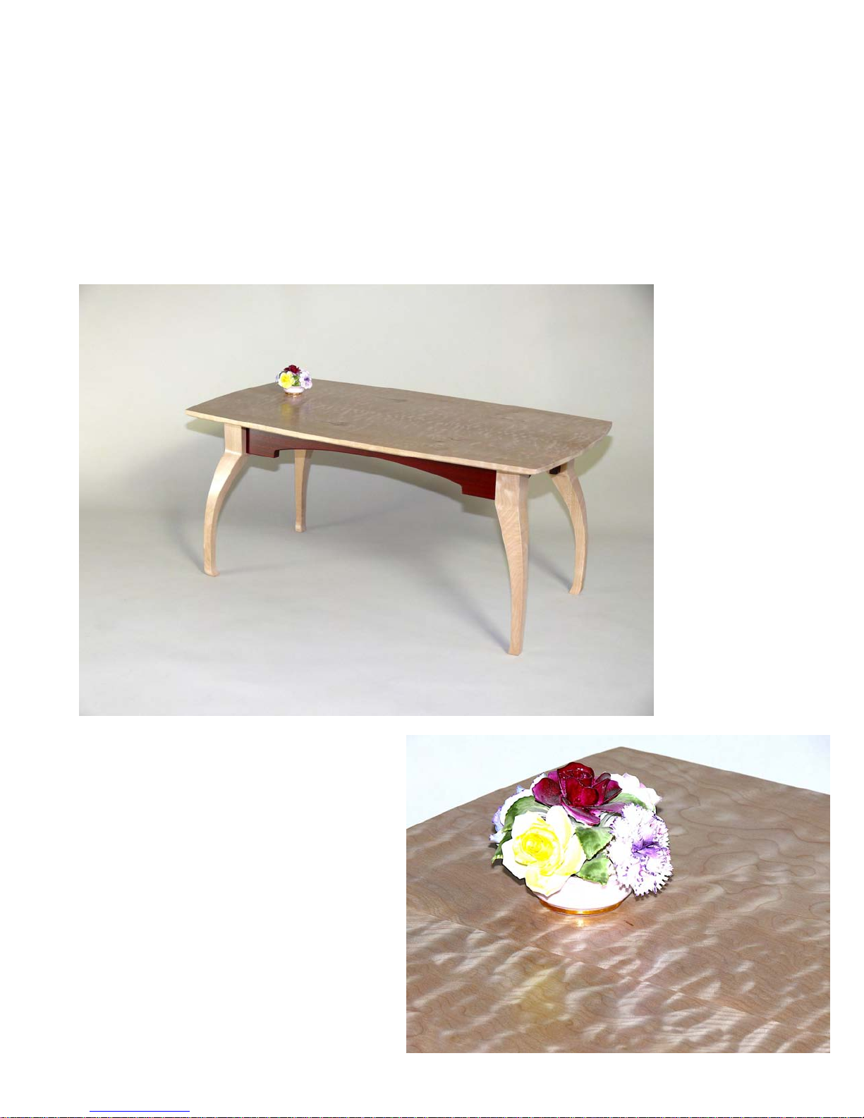
Small Conventional Coffee Table
The legs are cabrio style cut from glued
up blocks of Maple. The Blood Wood
skirts are attached to the legs with one
Domino loose tenon which is more than
strong enough given the small size of this
particular table. The top is attached via
“L” shaped tongue pieces screwed to the
underside of the top with the tongue in-
serted into
Domino
mortises
cut into the
inner face
of the
skirts.
We start by
gluing up
blocks
which will
form the
legs. Determine the
distance
you want
your cabrio
legs to
curve out
from the
inside of
the top of
This lovely small coffee table is constructed from highly figured Oregon
Big Leaf Maple with Blood Wood
skirts. The quilting in the top is so
pronounced that you have to touch it
to convince yourself that the top is
really flat. As this photo shows, your
eye is convinced the top is three dimensional with peaks and valleys.
The finish is a water based, environmentally benign pre-catalyzed conversion varnish that has been polished to a mirror like piano finish.
Page 24
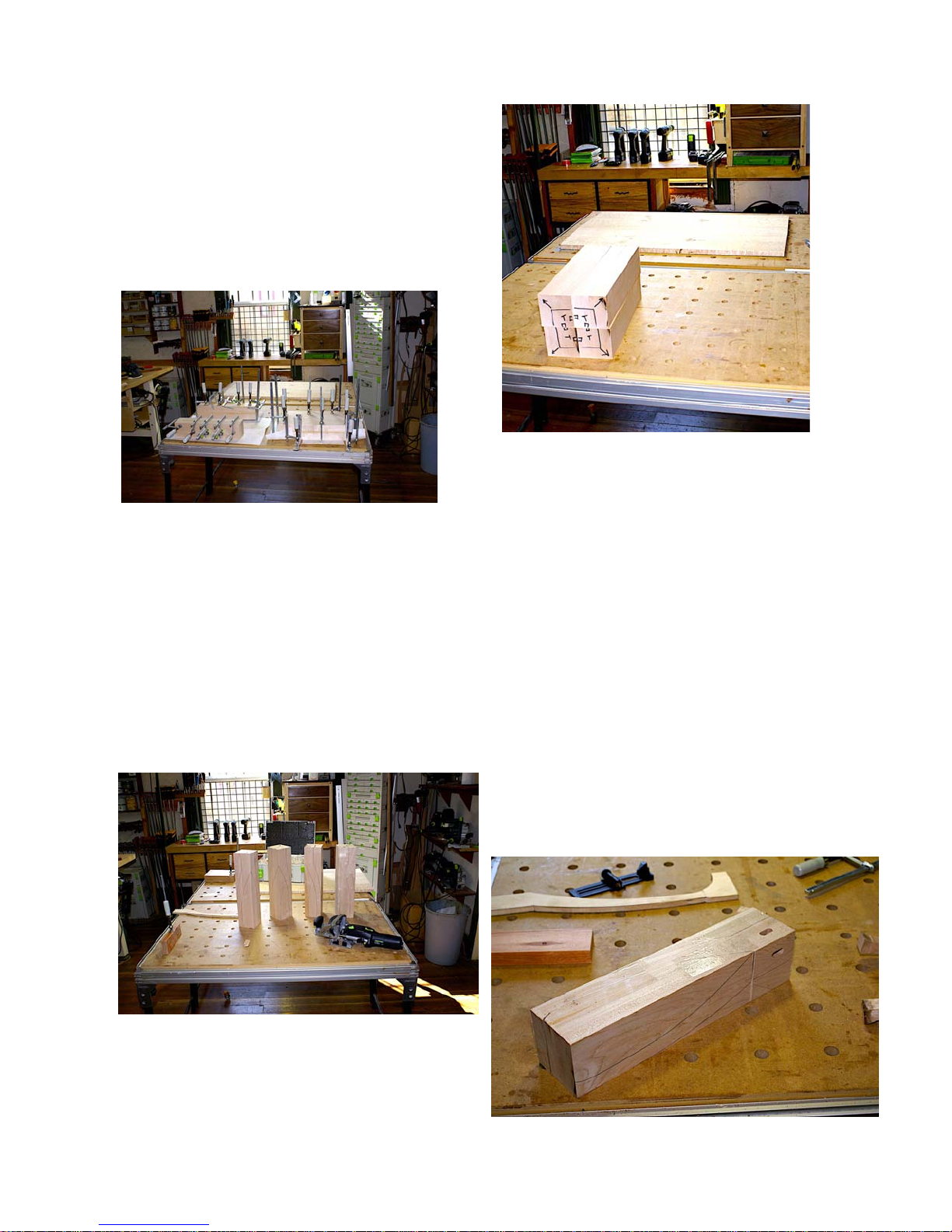
the leg where in mates with the skirt to
the outer most portion of the curve.
Make the block that size square and a bit
longer than the leg will be high. Do not
use Dominos to join these pieces to form
your blocks as the leg curve is likely to go
right through wherever you put the Domino tenon causing it to show once the
legs are cut out. Next, square up and
dimension the leg blocks. You can see
the template I used to draw the cabrio leg
outline on two adjoining faces of each
block lying on the Festool MFT just behind the leg block in the bottom picture.
Next, place the four blocks together so
the outline of the square top of the leg on
each block and draw an arrow pointing
diagnonally out to what will be the outside
of the cabrio curved leg.
Behind the stack of four leg blocks you
can see the glue up for the top. That was
done using Domino M&T as described in
the previous section under “edge-toedge” joints.
Now set up the Domino machine to cut
the leg-to-apron mortises in each face of
each leg blank as shown. I wanted the
skirts to be inset from the legs by 15mm
and the skirts to be 20mm thick. So I set
the fence on the Domino machine to be
25mm up from the cutter centerline as
the corner where the top of the cabrio leg
outlines are common are all placed to the
center of the stack. Now roughly draw
Page 25

we discussed earlier. Simple to do, just
set the height pointer to 25mm and lock
the fence as shown in this photo (the
Domino body has been removed from the
fence so you can more easily see the
height setting).
Place the Domino fence on the leg surface where you want the mortise and
slide it to where the centerline mark
aligns with the mark you made on the leg
blank, turn on the Domino machine and
make the cut.
You will be amazed at how
accurately you can position
these mortises with “just” the
visual reference marks. Using an adjustable square or
other “story stick” and a sharp
pencil or knife to make the
mark, both mortises in each of
the four legs will be very close
to being in exactly the same
place. And, it will only take a
few minutes to cut all eight
mortises.
Thank you Domino machine!
Now make a mark on each leg about half
the maximum height of the skirt down
from the top of each leg on the two faces
which will form the inside top of the leg.
Make this mark with an adjustable square
set to the desired length so it is the same
on all four legs. Set the square aside and
don’t move the setting as we will need it
to align the Domino mortise we will cut in
the ends of each skirt piece. The mark
indicates the centerline for the mortise
relative to the top of each leg and the
fence height setting establishes the centerline for the mortise relative to the outside of each leg. Put on the cutter you
need, set the mortise width to minimum,
and set the depth of cut to be half the
nominal length of the Domino tenon you
intend to use. As I recall I used a 10mm
x 50mm for these legs so the mortise
depth was set to 25mm.
(Note: you can also just hook
the spring loaded pins over
the ends of the leg and skirt to align them
for this cut as well, if you want to.)
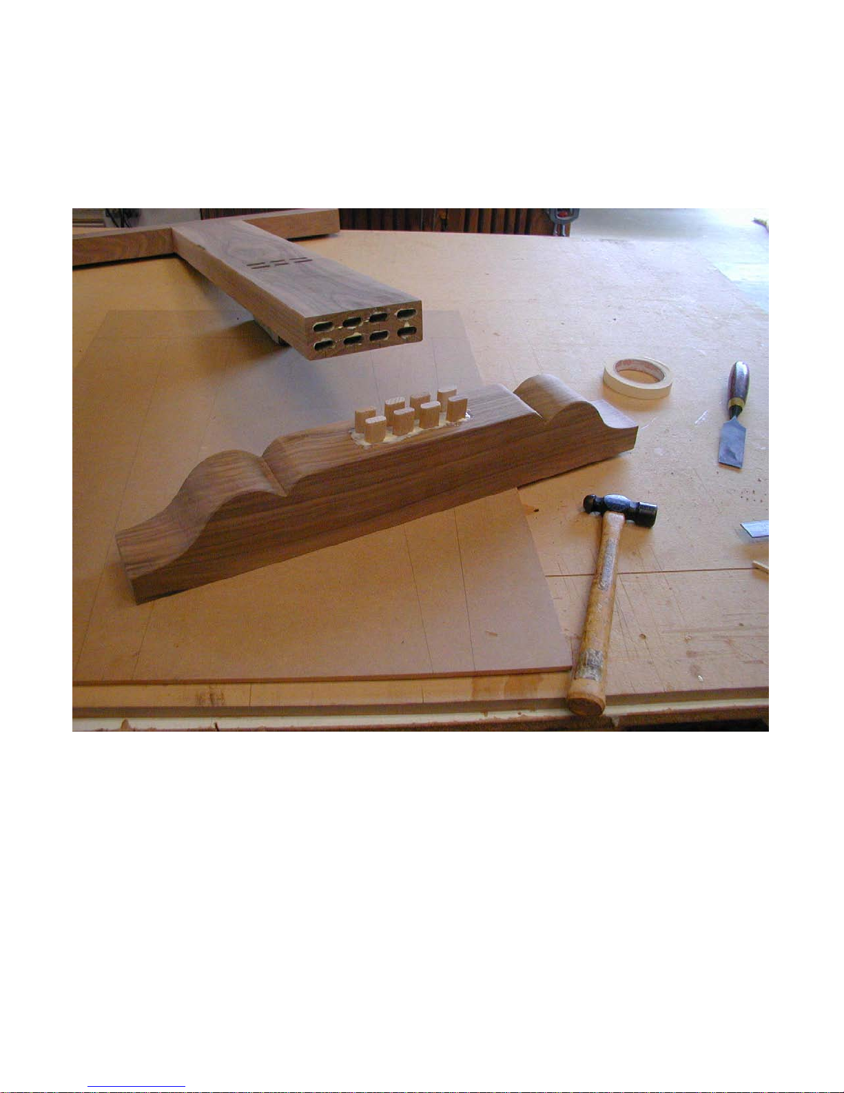
Take each leg blank to the band saw and
follow the leg shape you drew on one
side of the cabrio leg with the template.
Save the off cut piece and tape it back in
place with clear package wrap tape. If
you look carefully at the photo on the bottom of the last page you can see the saw
kerf and the glare of the package tape
holding the off cut piece on the leg blank
shown.
The taped-on off cut piece reestablishes
a flat surface for making the second leg
profile cut on the band saw. When you
get finished with all four legs, you will
have quite a stack of scrap as shown in
the photo on the next page.
Page 26

machine to be plenty good enough for
you to cut all the mortises on the minimum width setting allowing the tenon to
do the leg top to skirt top alignment for
you. However, if you prefer to cut a wider
mortise slot and do your own alignment,
there will be very little difference in the
leg-to-skirt joint strength as most of the
strength of a M&T joint is derived from
the glue on the faces of the tenon, not on
the edges of the tenon.
Sand all the legs to final shape and dimension and cut the profile for the skirts.
I like to break the edges on things like
skirts with a 45 degree chamfer router bit
so the hand feels a smooth, rather than a
sharp edge.
Once the skirts are finished, use the adjustable square set as before to mark the
centerline of the mortise to be cut in each
skirt. Mark each from what will be the top
of the skirt so you are always using the
same reference and to make sure the top
of the skirt and the top of the leg line up.
Reset the Domino fence height to be half
the skirt height, keep the width set to
minimum and the depth to the same setting you used for the legs. Place the
fence on the outside face of each skirt
piece, slide the Domino until the center
mark lines up with your mark, and make
the cut.
Next, shape and sand the top. I like to go
up to 800 grit before the first seal coat
when I want such a high gloss glass-like
finish such as on the top of this piece.
Seal it on all surfaces, sand again to 800
grit and do the build coats. Sand the final
build coat to 800 and do one light top
coat. Set the top aside to cure for a couple of days before polishing.
A bit of a confession here - I have done
the polishing long enough to be comfortable polishing a piece after just a few
hours of curing, but I don’t recommend
that to you until you gain a lot of experience as it is easy to burn the finish when
it is so young. Once it fully cross-links, it
will polish without burning.
For more detail on water based finishes,
buffing and polishing take a look at the
manual available on the
targetcoatings.com home page.
If you are nervous about your ability to
cut all the skirt mortises to the same centerline you used for the leg mortises, then
reset the slot width to the middle setting
before you make the skirt mortise cuts.
The resulting skirt mortise will be wider
than the leg mortise providing some adjustment room at assembly time.
That said, I think you will find the visual
reference accuracy built into the Domino
While the top is being finished, assemble
the legs to the skirts with glue, legs
pointed up. Clamp the skirts down to the
top of a flat surface like the MFT to register the top of the skirt and the top of the
legs to the same plane and square that
assembly while the glue dries.
Finish the leg and skirt assembly and you
are ready to mate the top to the legs by
Page 27

machining Domino mortises on the
inside of the skirts as shown in this
photos.
It is easy to make a tongue
block with the base of the
tongue up slightly less than
7mm from stock that is
12mm thick. That will present a 5mm tongue to insert
into the 6mm slot cut on the
inside of the skirts. By keeping the bottom of the tongue
a bit less than 7mm, when
you screw that block to the
underside of the table top the
tongue will press the skirt
firmly to the top while still allowing it to move with normal
seasonal changes in humidity.
Invert the now finished top on a soft,
flat surface. I use a rubber sanding
pad but an old blanket will work as
well. You do not want to scratch the
top you worked so hard to polish.
Don’t worry though, if you do
scratch it, you can remove the
scratch by repolishing.
The easiest way to cut the Domino
mortises into the inside of the skirts
is to cut them while the skirt and leg
assembly is clamped to the flat reference surface. Remember that the
distance from the base of the Domino fence to the centerline of the cutter is
10mm. If you use a 6mm cutter with the
base on the reference surface a 6mm slot
will be centered up 10mm leaving a 7mm
distance from the bottom of the slot to the
reference surface which is on the same
plane that the bottom of the top will be on
when you mate the two components together.
You can also cut these mortises from the
top side if you want more bottom of slot to
underside of top dimension. Set the
Domino fence height to wherever you
want the center of the slot. Add on the
auxiliary base for stability. Place the
fence on the top edge of the skirt with the
auxiliary fence held to the inside face of
the skirt and make the cuts. Machine
tongue blocks to match, screw them
Page 28

down as shown and you are done. Al-
most.....
Be sure to sign and date your work before delivering it to family, friends or cus-
tomers. Generations from now that
owner will want to know who built your
beautiful piece of art furniture and when.
Page 29

Next let’s move to another more challenging coffee table that will help illustrate
even more and different ways the Domino
machine will speed up and improve the
quality of
your work.
two hands to do a one handed operation not good.
I hit on the idea of the “convertible” coffee
table shown
here.
This is a
unique design for a
special application.
The customer
wanted a
coffee table
with casters, a
drawer, and
an intermediate shelf
for her
downtown
condo. She
is an artist of repute and has decorated
the condo in a tasteful blend of contemporary and traditional styles, but with a
definite artist’s flair.
She also likes to
change things
around as she rotates her own art
into and out of the
space.
It was important for
the coffee table to
both blend in and
still be a functional
art piece.
Usually wheels
and drawers do not
work well in the same piece: go to open
the drawer and the piece moves requiring
The upper
photo
shows the
table in the
“contemporary” position while
the lower
photo
shows the
“traditional”
position.
Converting
from one
look to the
other is
simply a matter of lifting off the top, slipping out the casters, inverting the base
and leg unit, turning the drawer upright
and replacing the top. In either configura-
tion the top is indexed to either the
legs or the base
via hidden Domino
tenons.
The base contains
hidden casters and
the drawer. When
in the contemporary mode it rolls
easily from place to
place without the
awkward look of
exposed wheels.
With the drawer down low there is less
tendency for the table to roll while opening the drawer for access.
Page 30

Inverted into the traditional
mode the table looks more
fixed in the environment and
the drawer opens easily in the
traditional way.
The book matched intermediate shelf and legs in Oregon
Big Leaf Maple compliment the
Black Walnut of the top and
side skirts. The top is made up
create a maple frame
around the
walnut skirts
and drawer
fronts when
the table was
in either
mode. That
meant that
the skirts
could not
simply be attached to the upper
and lower platform pieces or one
would not be able to assemble it
as the last edge would either not
fit or would have to be attached
without positive location by
something like pocket hole
screws.
of four book matched panels floating inside a picture frame with intermediate cross members and is a real
knock out when seen in person.
The trick is to make it all work and
that is where the Domino machine
comes in. What is a bit tricky here
is the need for both an upper and a
lower platform made from maple
that separates the walnut side
skirts and the need for the drawer
box to be able to support both a
drawer that pulls from both directions and the hidden casters.
The solution came in the form of
a unique platform frame to leg
joint that, as we will see in a
moment, involves a dado in the
upper and lower frame members
which holds the walnut skirts in
proper registration, a skirt-to-leg
Domino M&T joint to keep the
short skirts that flank the drawer openings
I wanted the upper and lower platforms to be mated to the legs to
Page 31

registered to the legs, and a Domino mortise and tenon frame-to-leg connection on
both the upper and lower frames to provide the strength necessary to offset the
leg stress imposed by rolling the unit
around and/or converting it from one
mode to the other.
Let’s see if I can describe and show the
construction details well enough for you
to follow.
We will start with the legs. Like the previous coffee table, this unit features a
simple cabrio leg that is cut the same way
as the more complicated curved cabrio
leg we saw before. In this case the legs
just flair out in both dimensions so they
look right in either mode. In this photo
the leg blanks were glued up, a template
used to mark the flair, and a band saw
used to cut the rough shapes shown
here.
This is the same process we used before
except this time I waited to cut the mortises until after the legs were formed because you can see from the photo that
we need three Domino mortises on each of two sides
of each of four legs. The
upper and lower horizontal
mortises will attach the legs
to the platform frames while
the vertical mortise will attach the skirts to the legs.
By using the saddle fence
shown in detail above, the
Domino machine can strad-
dle the square part of the leg
to cut the upper mortise from a penciled
reference mark using the same technique
of an adjustable square or story stick to
mark exactly the same distance up from
the end of the legs on both sides of all
four legs.
The lower horizontal mortise is cut with
the leg standing upright on a flat reference surface and with the Domino base
also sitting on that same flat reference
Page 32

surface. We know that the Domino baseto-cutter centerline is 10mm. Our platform frame is made from 20mm stock so
the resulting mortise will be exactly centered on the frame and hold the frame
flush with the end of the leg once the
mortise is cut in the center of the frame
members.
fence to one-half the leg
thickness so the leg will
snugly fit inside the saddle
fence. Then I slide the Domino machine up until my mark
is aligned with the mortise
centerline on the Domino machine fence. Then the clamp
As you can see in this photo the saddle
fence keeps the leg standing upright and
centered over the cutter laterally while the
reference base puts the center of the
mortise 10mm up from the end of the leg.
While you can hand hold the pieces for
the bottom-most horizontal mortises (the
saddle fence & flat reference surface secure the work piece and all you need to
do is hold it tight against the Domino machine during the plunge cut), it is not easy
to hand hold for the upper horizontal mortise cuts.
Since these mortise slots are being cut
after the legs have been roughed to
shape, I clamp the Domino to the leg so
neither the Domino machine nor the leg
can move during the plunge cut. As we
did before, I set each side of the saddle
Page 33

holds it in that position while the cut is
made.
To check to make sure both mortises in
both sides of all four legs line up correctly, I put a dry (no glue yet) Domino
tenon into each joint and push the legs
together as shown in the top photo on the
previous page. If the mortises are all
perfectly aligned, the legs will go together
easily. If they are not, the legs won’t go
together at all.
As before, all 8 mortises wound up in exactly the right places by indexing one off
of the leg end and the other off of a visual
reference mark. That would only work if
all the Domino measurements, machining
and markings are all spot on - and they
are.
Now we need to cut the vertical mortises
which will index the side skirts and the
skirt pieces beyond the drawer openings
to the legs. To cut these I needed to set
I keep a set of metric gauge blocks
around just for such purposes. Remember the step block built into the base of
the Domino machine? That slides back
and forth to establish a step that will position the Domino fence up half that
amount from the centerline of the cutter.
One of those stop block settings is for
40mm thick material and it will position
the cutter right in the center, or 20mm up.
We need 22.5mm up to center on our
45mm legs, so I placed a 5mm gauge
block between the step and the fence to
register the fence for a 45mm stock
thickness to put the cutter centerline up
22.5mm.
the Domino fence to be exactly 22.5mm
to center those on the 45mm thickness of
the legs. They must be spot on because
those skirts will sit in a dado we will cut in
the platform frames and they have to also
index into the legs via these Domino M&T
joints.
I could have just eyeballed 22.5mm on
the height scale and pointer, but the
gauge block method is much more precise.
To establish the reference to center the
mortise between the other two mortises I
used the auxiliary spring pin wings that
attach to the dovetail in the base of the
Domino fence. You can see that in the
photo to the left. By hooking that spring
pin over the end of the leg and placing
Page 34

the fence firmly on the flat part of the leg,
I could cut the vertical mortises just as
accurately as the horizontal ones....great
fun and it takes only minutes to do.
I know it looks a bit complicated in these
pictures, but when you have a Domino
machine in your hands and start using it
you will see just how fast and accurate
these cuts can be.
The next step was to machine the
upper and lower platform pieces to
size and then machine the dado that
will hold the side skirts. Here I have
clamped one of the platform pieces
down to the top of a Festool 1080
MFT. I have five MFTs in my studio
and they all are in use constantly as I
just do not know of any better way to
hold work pieces steady while you
machine them.
In these photos you can see the Domino
machine with the saddle fences set for
the 50mm width of the platform frame
members and the fence set to center the
Domino mortise on the 20mm thickness
of those pieces.
Drop the Domino machine onto the end
of the work piece, slide it forward until the
face of the Domino machine registers
Page 35

with the end of the work piece and plunge
to make the cut. The result is shown on
the bottom of the previous page along
with one of the legs that it will mate to.
The photos on this page show how the
ends of the 10 x 10mm tongues on the
side skirts are cut back to clear the Dom-
how the vertical M&T joint between
the leg and the side skirt will make
up as the skirt slides in the dado
and onto the leg tenon.
The photo above is after all the
parts have been through final
sanding, ready for finish and actual
assembly.
ino tenon since the centerline of the tenon and the bottom of the dado are both
10mm. (Suppose we should invent a
term and call this a “Dominoed dado”
joint? grin.)
The views here are of the platform
frame member that will index to the
ends of the legs. The photo above is
from the end of the leg view and the
photo below right is taken looking
down on the platform frame with both
the leg and frame members flat on
the reference surface.
Notice that the side skirt 10 x 10mm
tongue is cut back to clear the upper
Domino M&T joint just as was done
to clear the bottom frame-to-leg joint.
It all works like a big puzzle and is
much easier to do than to visualize
beforehand or to see in small photos.
In the photo right you can also see
Page 36

More work was required to cut the
dado in the inside of the top most
frame member to accept the maple
book matched panels you saw in the
opening photos. There also was
machining to do to hold the drawer
slides and the bases for the hidden
casters.
make the four square openings for
the book matched top panels.
Mitered corners are not strong
enough for such an application so
Domino M&T joints were used to reinforce them as shown below left
and in detail below.
The Domino fence was set to center
the bit on the 20mm thickness of
these pieces. I used an adjustable
Now we will look at how the top was
constructed and how the whole project came together.
The top is a picture frame with mitered
corners and interior cross members to
square to establish the length I wanted
each mortise to be down from the outside edge of the 45 degree frame corner and used that to make a mark on
both ends of the four frame members.
Pressing the Domino fence down on
the top face of each frame member
and the Domino face snugly against
the 45 degree miter cut on the end of
the frame pieces, I slid the Domino to
the point where the bit centerline was
aligned with my mark and made the
cut. As was discussed in the earlier
section on miter corners, look carefully to
make sure your mortises do not go
Page 37

through to the outside of the frame.
Shorten the tenons by cutting them if you
have to.
In the upper left photo the top is registered into the end-of-leg to underside of
top Domino M&T joints to make sure the
legs and top will properly
mate in the final assembly.
With everything square and
accurate I could invert the
piece and do the top of
frame to underside of top
Domino M&T joints since
those are in a different place
than the end-of-leg to underside of top joints.
Once all the components fit
together correctly, it was off
to final sanding and then to
the finish room.
Notice also how the frame center cross
members are held in Domino M&T joints
in both directions to make for a very
strong outer frame for the walnut top.
The final steps are test assembly of all of
these components. When these pictures
were taken I had already finished the top.
The photo above shows clamps holding
the leg-to-panel frame joints tightly,
clamps holding the whole assembly into a
known square corner, and clamps holding
the skirt pieces on each side of the
drawer openings tightly to the leg-to-skirt
M&T joints. I removed the clamps holding the unit to the known square corner
front to back so you could see the details
more clearly.
For more info on clamping into a known
square corner, look at the manual I wrote
about the Festool MFT which is available
for download from the festoolusa.com
web site.
Page 38

The following photos show how I like to
finish all components in the flat, before
final assembly.
With no top in the way it is easy to
polish the book-matched maple panels that form the intermediate shelf
and to spruce up the skirts, legs and
frame members.
The last step was the signature block
and then notifying the customer that
the piece was ready for pick up.
They were thrilled, and so was I!
Page 39

Let’s switch gears a bit from how the
Domino machine does all sorts of very
precise M&T joints to how it can do many
other things with ease as well.
Wine Service Center
First, let’s look at an interesting wine
service center, this one made from Purple
Heart and Maple Burl. The sides and
back are done as R&S with 10mm thick
slabs of maple burl as the panels. The
the legs and upper
frame by tongued
splines screwed to
the underside of
the top. The bottom shelf is held to
the leg stretchers
by wide Domino
mortise slots and
tenons inserted
without glue to allow for seasonal
expansion and
contraction of the
shelf.
doors slide in machined grooves cut in
the top and bottom front frame members.
They have to fit the opening tightly to
look right and feature a very unique
Domino enabled moving pin mechanism
that we will see in detail later.
A curved maple drop fits into a sliding
dovetail groove to soften the opening below the base of the upper cabinet on the
front, back and sides. The top is held to
Let’s build it.....
Page 40

As before, let’s start with the legs. Glue
up stock to make four blanks. In this
case the legs flair out side to side, but not
front to back. Construction is the same,
but we only need to scribe our template
on one face, not both faces as is the case
with cabrio legs.
and lower side frame members
and to hold the leg stretchers.
Since those frame members are
oriented with their wide face up
and down (where the front and
rear frame members are oriented with their narrow edge up
and down) we need to cut those
mortises in a vertical, rather
than horizontal orientation as
shown below.
While they can be cut before the
legs are profiled, I find it easier
Dimension all four leg blanks to be exactly the same size and perfectly rectangular so we can reference from both
sides.
We will need Domino mortises cut horizontally (red arrows) on the faces of the
legs that will be in towards the center of
the completed piece. One will be set
10mm down from the top of the legs to
hold the front and rear upper frame
members. The other will be set down
near where the leg flair begins to hold the
lower front and rear frame members. The
position of that mortise determines the
overall depth of the cabinet portion of the
piece.
We also need Domino mortises cut in the
sides of the legs that will face front to
back (green arrows) to hold the upper
to do so after profiling because the bottom frame is made up of pieces in different orientations (front and back narrow
edge visible, sides wide face visible) and
it is easier to see the relationship between these two locations after the leg is
cut than before.
To do the locating I tape the cut off piece
back onto the leg to provide a reference
surface and more flat space to support
the Domino base. You can see this in the
Page 41

photos below. Here is the locating of the
leg stretcher mortises. With both sides of
the leg curved you need the cut off piece
to get a reference. Be sure to align the
cut off pieces in the same place up and
down on the leg so the relative saw kerf
is the same on all four legs.
While I did not need it here, use
of the auxiliary fence would provide more stability for the Domino machine for cuts such as
these.
Next comes the cutting of the
Domino mortises in the ends of
the frame members. The front
and back members are cut horizontally by use of the saddle
fence shown here and on the next
page.
The mortises cut in the front and back
upper and lower members are not cut
in the center of the 50mm dimension.
Instead they are offset a bit so their
edges will line up properly with the side
Page 42

frame members. In the photo above you
can see how one side of the fence is further away from the bit center than the
other. In the lower photo on the previous
page you can see how this results
in a different centerline for the mortise than for the dovetail groove
which will hold one of the curved
maple pieces.
such as cutting the tracks for the
door slides, cutting the dados to
hold the bottom of the cabinet,
cutting the dados that hold the
side burl panels, etc.
Meanwhile, let’s see what the
skeleton looks like. The shelf is
not in place for these photos. We
will get there a bit further on.
Even seemingly difficult alignments
like this one are easy to do by using the lines scribed on the clear
plastic window and the scales on
the upper portion of the saddle
fence.
To make the cut, clamp the work
piece to the top of the MFT, drop
the saddle fence over it and push
the Domino up snugly to the end.
Set the depth and the width of cut
and plunge to make the cut....fast,
easy and very accurate.
The next several photos will show a mock
assembly of the main structural members
so you can see how they go together.
Before we actually assemble the piece,
however, there is more machining to do
Page 43

These are the main pieces of the skeleton. Note that the top edge of the front,
back and side frame members all align
with the top of the legs. The lower edge
of the front, back and side frame members align together.
Now that we see what the structure is
going to look like, let’s go back and
show some really innovative uses of
the Domino machine.
Page 44

The first thing to do is assemble the two
sides after cutting the groove for the burl
side panels. These photos show this sequence.
Once the sides are glued up and squared
with the leg stretchers in place, we can
turn our attention to building the back rail,
stile and burl panel and the two front
doors.
In the photo above
notice how handy the
Festool DX 93 E detail sander is for
reaching into tight
spots such as where
the leg stretchers
meet the legs. Any
glue squeeze out on
purple heart really
shows once the finish
goes on so be sure to
sand very throughly.
The photo above
shows a booboo.
When I first started this
piece I thought it would
look good with a book
matched maple top.
You can see the glue
up here. But, once the
piece was completed it
became clear that a
maple top was “over
the top” so I crafted the
purple heart top you
see in the final piece.
Page 45

Now let’s construct the rail, stile and maple burl back panel. The doors will be
done the same way. We saw earlier how
I now use Domino M&T joints cut inside
the tongue and groove joints of the rail
and stile components to both reinforce
these joints and to make them selfaligning.
With normal rail and stile construction
when you clamp up the assembly the rail
pieces with the tongues cut in their ends
can slide down the groove cut in the stile
pieces leaving the assembly either out of
square or with an unsightly gap between
the edge of the rail and the end of the
stile.
The Domino M&T eliminates that misalignment by holding the edge of the rail
flush with the end of the stile speeding up
the whole process by much more than
the time required to cut the Domino mortises in the first place. That is what I call
a real win-win.
The same is true with respect to placement of intermediate stiles as we will see
shortly on the back assembly for this
piece. Normally you have to measure
and mark the location for those and make
sure the intermediate stile stays in the
right place while you glue up and clamp
up. On many occasions that turns out to
be quite a time consuming process.
Well, watch here while the back rail, stile
and panel components go together. The
Domino M&Ts keep it all aligned without
me having to do anything.
While this would not necessarily be
true for everyone, I can justify the cost
of the Domino machine for this one
reason alone!
Page 46

Page 47

The self-aligning feature of a Domino
M&T joint cut inside a normal R&S
tongue and groove joint really speeds up
the process of assembling a multi-panel
component like the back on this piece.
grain component that will attach to the
long grain of the back lower stile, we can
screw these two together with the screws
placed inside the sliding dovetail slot.
As we assemble we can slide
the lower maple curved
pieces into the sliding dovetail
slot while we insert the Domino tenons to affix the back
and the front frame members
to the sides we completed
earlier.
Next we suspend the shelf
With the back now finished it is time to
mate the dovetailed and end mortised
rear lower frame rails (which also have
the groove that will hold the bottom of the
cabinet in place) to the bottom of the
back component. Since this is a long
between the two leg
stretchers using Domino
tenons inserted dry (no
glue) into wide mortises cut
on the inside of the stretchers and the ends of the
shelf. From previous descriptions, aligning these
Page 48

mortises should be easy for you to
visualize. Here is the piece assembled (minus top and doors), squared
up and waiting for the glue to dry. All
of the major joints are Domino M&T
joints so assembly is fast and self
aligning.
mum depth) is cut parallel
with and centered on the
bottom and top surfaces of
the door.
Then I turned the Domino
machine sideways and cut
a 5mm mortise centered
on the 10mm mortise both
side to side and top to bottom.
A 10mm tenon was drilled
to accept a metal pin a bit
Now let’s revisit the sliding doors.
Earlier I said that the doors had to fit
snugly into the door openings to look
right. The problem with most sliding
doors is they have to fit loosely
enough to lift up into a top track to let
the bottom free of the bottom track to
get the doors in and out. That simply
looks bad and is not pleasing to use.
So, let’s use the Domino machine to
do something far more satisfying and
sophisticated, a sliding pin assembly
that can be withdrawn up into the
door itself and then lowered into the
door tracks once the snugly fitting
door is in place.
In the lower close-up photo you can
see that I cut two overlapping mortises. One (10mm wide and maxi-
Page 49

smaller in diameter than the width of the
sliding door tracks machined in the front
upper and lower frame members. I cut
the length of the tenon so the end of the
pin would be flush with the bottom or top
surface of the door when it was fully inserted into the 10mm mortise. A hole
was then drilled into the face of the
10mm tenon through the center of the
5mm mortise so a small screw can secure the 10mm tenon/pin unit either
withdrawn up into the door or with it low-
ered down into the track.
Slick as can be we have a snugly fitting door with hidden sliding pins yet
the doors can be easily removed and
replaced any time.
This same double overlapping mortise idea can be used for making nice
hidden latches as well. For a latch
cut the 5mm mortise in the front of the
door and replace the screw with a
nice small dowel or decorative rod.
Slide the rod or dowel back to retract
the Domino tenon to release the door.
It doesn’t matter whether you put the
latch at the top, side or bottom of the
door. It will work just the same way.
Get creative with the dowel or rod
component and you can create all
kinds of neat looks.
Page 50

Now that we have seen how the Domino
M&T can be used for joining pieces,
aligning pieces to be joined by other
means, and used for things like hidden
door slide pins and latches, let’s move to
still two more projects to find even more
innovative uses for the Domino machine.
Double Pedestal Desk with a
Twist
Double pedestal desks are very common
and many woodworkers eventually get
around to building
one either for
themselves, some
other family
member or a
friend. They
mostly all look a
lot a like as the
top sits on two
pedestals, usually
with drawers both
in the pedestals
and in the bridge
between the pedestals.
The “finished product” pictures were
taken in a show context in one corner of
my booth space along with a couple of
the other “Domino inspired” pieces we
have already covered so excuse the
background clutter.
In this case the client is an active, energetic person who spends a lot of time at
her desk. She is slender and tall with
long legs and her most comfortable working position is sitting in her chair with her
legs folded. That meant the space between the pedestals and from the floor to
Some of these
designs can be
quite handsome.
Sometimes the
requirements and/
or the aesthetics
call for something quite different while still
maintaining the double pedestal look and
function. Here is an example we will follow because it holds a number of hidden
Domino “tricks” that greatly simplify construction and speed up what otherwise
would be a long and involved build process.
the underside of the desk top had to be
maximized.
This piece was a surprise birthday gift
from her husband so I couldn’t engage
her in the design process as I normally
would do. Fortunately, I had designed
and crafted other pieces for them so I
was familiar with her tastes, home and
decorating style.
Page 51

Retro, modern, clean, colorful and functional all describe what I was
after, and what I though she
would want. She also
needed to be able to reconfigure her work space to fit a
variety of the projects she
does so “flexibility” also had
to be added to the equation.
The “last” design requirement was she needed to
temporarily house and hide a
tower style computer until
she purchased a new lap
top. Then that pedestal
needed to morph to some
other use. Oh, and they
move frequently, so transportability was an issue, too.
Ready to give up yet? Well, don’t. I
found a way to meet all of these requirements and design aesthetics that landed
me a really big hug when she first saw
the finished piece.
The husband arranged to have a very
small “happy birthday” placard discretely
tucked away on one corner of the top so
she would
eventually see
it when he
brought her
into the show.
She entered
the booth and
after the greetings, she began, as she
Page 52

always does, to examine the various
pieces on display, oohing and awing as
she went. A friend with them noticed the
“happy birthday” placard on the desk first
and nearly fell over. The guest contained
herself until the client finally saw the card
as well. Then the tears and hugs began.
Can’t beat that for a reward.
Now let’s look at the “Domino content” of this project.
Transportability meant that
the top needed to come
apart from the pedestals.
The requirement for maximum space between the
pedestals and between the
ground and the bottom of
the top meant the top had to
be very strong to span the
distance, yet there would be
no conventional pencil
drawer bridge to help support it.
The solution was to build the
top as a two piece torsion
box with the top and bottom
layers of the torsion box
joined with long sliding
dovetail stringers as can be
seen in this detail of one
front corner of the top assembly.
There is a lot going on here. The top is
one solid glued up slab of Oregon Big
Leaf Maple so it will expand and contract
a lot front to back, summer to winter. It
also would want to warp in sympathy with
the annular growth rings in each of the
individual boards that make up the large
glued up top.
Sliding dovetail stringers going front to
back and spaced about 300mm apart,
such as I use under solid wooden kitchen
counter tops, will solve the warp issue as
they will hold the top plate perfectly flat
for generations to come.
I could also dovetail the bottom of the
same stringer to be the means of holding
the bottom plate of the torsion box to the
top plate. But, you can’t put those sliding
dovetails too
close to the
edge of the
top or the
stresses
from normal
seasonal
movement
might break
off the
edges of
the dovetail
grooves.
Moving the
outboard
most
stringer inboard far
enough for
strength
would solve
that issue.
The design
of the piece required the top be banded
with Blood Wood on all four sides to
make the top look massive and allow it to
float visually off of the blood wood risers
on the top of each pedestal. That imparts
a distinctly Oriental flavor to the piece
that makes it both modern and clean at
the same time.
Page 53

But, how do you hold the blood wood
banding across the end grain of the maple top? The top has to move front to
back so you can’t just attach the
blood wood to the top.
The solution was to add a
dovetail groove to the inside of
the blood wood and a dovetail
stringer filling the space between the edge of the top and
the outside edge of the torsion
box stringer as shown in the
photo on the previous page.
Domino mortises were cut on
the inside of the space-filling
stringer and the outside of the
torsion box stringer (shown
here by the red arrow). Domino
tenons were glued to the dovetail stringer which is attached to
the blood wood end banding.
Then, after the top was completed, that assembly was
glued into the mortises in the
torsion box stringer. That holds
the blood wood edge firmly in
place but the top plate is free to
move, both sliding beside the
blood wood and across the
dovetailed torsion box stringer.
couple of pages back. The slide-out work
surfaces are what allow her to configure
the work space to fit the requirements of
The lower photo shows the underside of the torsion box top.
The space between the dovetailed stringers running front to
back to hold the top plate to the
bottom portion of the torsion
box were spaced to allow the two different sized pedestals to fully support the
top assembly no matter which pedestal
was on which end. More on that later.
The spaces between stringers support
the slide-out work surfaces you saw a
her various projects. The center pull-out
is a shallow pencil tray that can be inverted to make yet another work space.
Page 54

So that is how Domino helped solve the
differential wood
movement issue
between the blood
wood long grain
edges and the
maple wide grain
top. Now, how
about the blood
wood banding
across the back?
It could just be
screwed in place,
but that would
look ugly.
The solution here
was to Domino
M&T maple spacers to the inside of
the rear blood wood banding to form a
series of “tongues” the same thickness as
the distance between the top plate and
the bottom portion of the torsion box.
even more wiggle room for those screws.
You can
see that
in the
bottom
photo.
The trim
is inverted
so I can
countersink into
the
edge
that will
be
against
the top.
I drilled a hole in them that was larger
than the diameter of the washer head
screws I intended to use to hold those
tongues to the underside of the top. That
way I could pull the blood wood banding
up to within 1mm of the back of the top
plate and secure it with the
washer head screws to the
under side of the top. Now
that band will move with the
top in and out as the top
expands and contracts.
The oversized hole will take
up any error if the top wants
to contract more than I allowed for.
I also used a Festool
counter-sink on the side of
the tongue that would be
against the top to provide
Page 55

Here you can see how the rear corners
fit so nicely while properly allowing for
the movement.
The next step was to provide for the
banding across the front. I made work
surfaces by Domino M&Ting (is that becoming a verb?) the plywood extending
work surface to a side slide that would
hold the work surface flush with the underside of the top as shown here.
Worked like a charm!
The whole top can simply be lifted off and
transported separately, yet it is so strong
you could stand in the middle of it if you
wanted to. With all the expanding work
Next, the blood wood banding was affixed
to the front of each work surface and the
shallow pencil tray by more Domino M&T
joints.
surfaces closed, the top
looks like one thick monolith
that creates a strong horizontal line to accent the clean,
modern look. When you ac-
tually see the desk, the blood
wood spacers that hold the top up off the
top of each pedestal blend with the blood
wood band for a really slick effect.
Page 56

would be considered the “back” of the
desk?
The answer to this set of questions was
to make the pedestals look exactly the
same on both the front and the back and
also to make them look the same side to
side even though they are different
widths.
Good solution, but we will need to deal
with the wood movement issues since the
back of the drawer pedestal and both
ends of the open pedestal need wide
grain solid maple from top to bottom to
simulate the look of the drawer fronts,
and the sides of each pedestal are rail,
stile and panel components where the
long grain of the side stiles will be running
across the wide grain of the faux drawer
fronts.
With the top completed it was
time to deal with the pedestals.
One pedestal was to be drawers
while the other was to hide the
tower computer and the peripherals. That pedestal was designed so the side you can’t see
in these photos is open. When
she changes computers, shelf
holes drilled in the insides of that
pedestal will allow a shelf to be
added and it can become a
bookcase.
Now, what if in a future location
the bookcase pedestal needs to
be turned around so it is open to
the inside of the space between the pedestals? Or, what if she wants to swap
pedestals side to side to put the drawers
on that side? Or, what if she wants to
have the desk in the center of a room and
access to the drawers from what normally
I thought long and hard about that one
until I remembered the slick Domino double mortise sliding door pin idea. This
time I cut wide mortises for 10mm tenons
along the edge of the side stiles and a
mating 5mm mortise running the same
direction on the inside face of the side
Page 57

stile. By gluing the
Domino tenon into a
tight fit mortise in the
back side of the solid
maple pedestal end, the
exposed end of the tenon would be visible
through the 5mm mortise slot as in the photo
at the bottom of the last
page (photo taken before the tenon was
glued so you can see
what is going on). Insert a screw with a
round head that was a
tight fit into the 5mm
slot and the answer was
at hand.
The screw into the tenon prevents the tenon from withdrawing from the unglued
mortise in the side stile while it still allows
the solid maple pedestal faux drawer
open pedestal as these slots are actually
quite attractive and will not detract from
the look when that open pedestal becomes a bookcase in the future. For the
back side of the drawer pedestal that will
never be seen from the inside and which
needed greater strength, I used the
Domino M&T (no glue) and pocket
hole screws going into oversized
front to expand and contract independently. You could also use a
dowel to pin the tenon, but the
screw is faster.
That technique was used on the
Page 58

through holes as we discussed earlier in
this manual.
In the photo above I have installed the
other side with all the drawer slides in
place and I am obviously please with this
slick solution.
Again, thanks, Domino ma-
chine!
In the lower photo you can see the faux
drawer end attached to one side, and below while I am installing the drawer
slides.
It was easy to build the
blood wood top-ofpedestal stand offs using the Domino M&T
joint to strengthen the
otherwise weak miter
joint. It is hard to see in
these small photos, but
the top of each pedestal
is plywood for strength
and each is inset into
rebates in the sides and
backs. The blood wood
stand offs attach to
those from underneath
where the fasteners
won’t be seen.
The last part of this pro-
ject was to make separate pedestal bases that each pedestal
would nestle into. The separate base allows the faux drawer fronts to expand
and contract into a recess without effecting the floor to top dimension.
Page 59

I added decorative corner dovetails made
from blood wood to the corners of the
pedestal bases to dress them up a bit.
While you may never make a desk such
as this, I hope some of the Domino machine specific procedures demonstrated
here find their way into your woodworking
experience. They really are great problem solvers.
Page 60

We are now to the final illustrative project
to show off the many, many different uses
for the Festool Domino machine - the butterfly leaf table.
But, before we start into that one, let’s
take a moment to talk about an easy way
your work piece is wider than that, you
can trap the work piece between the face
of the Domino and the edge of the top
while pushing down on the Domino fence
to register and hold the material in place
to place Domino mortises into thinner
work pieces like edge banding.
Making the mortise cuts is easy, holding
thinner or smaller pieces safely is not.
What I do is place thinner pieces on the
top of the aluminum extrusion that forms
the sides and ends of a Festool MFT.
The top plate is higher than the aluminum
extrusion by about 14mm so, as long as
while you cut the mortise. I also like to
register the end of the piece against a
stop so it can’t slide side to side while I
am making the cuts, especially if I am using one of the spring loaded pins for end
to mortise registration as I am doing in
this example.
Page 61

At the vary beginning of this manual I
said that the construction of a butterfly
leaf table was for many woodworkers a
bit of a rite of passage. Because it is so
difficult to build correctly using conventional construction
techniques, it is often a
frustrating experience
trying to get all the pivot
points to line up properly.
The construction techniques we will follow
here greatly simplify all
aspects of these interesting and useful tables. I think you will
find them helpful in expanding your woodworking skills into a
whole new range of
projects. At least, that
is my hope.
Butterfly leaf table
This example is a very small dining table
sized to fit an upscale arts and crafts
So, here goes.
style condominium which has no formal
dining room so it has to fit into the eating
space in the kitchen area.
Because it is so much smaller than a
conventional dining table, I designed it to
look like a library table when closed. This
one is made from Oregon Black Walnut
and Australian Silky Oak (often called
“Lace Wood” in this country). It is 850mm
wide by 1580mm long when closed. It is
standard height at 750mm. The leaf is
400mm wide so extended the table grows
to 1980mm long. In inches these dimensions are 33.5” wide by 62.25” long
closed (78” when extended) and 29.5”
high.
The characteristic of a butterfly leaf table
is that the leaf stores folded under the ta-
Page 62

ble top on hinges that allow it to automatically deploy and line up with the rest
of the table surface just by lifting one section of the leaf. In order to line up properly the pivot points where the
leaf folds and the pivot points
for the deployment mechanism
must be in exactly the correct
locations relative to one another and to the top of the table. Lining those up is what
generally makes this kind of
table tough to build.
As we will discover as we progress through this project,
here the deployment mechanism pivot points are set in
vertical sliding dovetails and
the leaf attaches to that
mechanism by screws placed
up from the bottom. What this
leaf assemblies and align them the way
they will be when the leaf is deployed.
Then the table mechanism is placed upside down on the aligned top and leaf as-
sembly. When everything is
square the pivot mechanism
(red arrow in this photo)
slides in the dovetail groove
until it is snug to the underside of the leaf. At that point
the leaf is screwed to the
pivot mechanism and the
dovetails on either side are
pinned in place so the pivot
point can no longer move.
allows is for all of the critical alignment to
take place after the table is constructed,
not before as is required by the conventional construction methods.
One of the last steps in the construction
process is to invert the completed top and
This results in the pivot points
being properly aligned so the
leaf will deploy as it should
without any measuring or
guesswork on the part of the
furniture maker. Nifty and
dead on accurate.
The leaf is guided up and over the table
skirt by the slides (green arrow) shown
above which also are set in sliding dove-
Page 63

tail slots so they can be properly adjusted
after the table is completed as well.
and the legs to allow the diner knee
space without hitting the leg structure.
Let’s go back to the beginning and start
with the functional design requirements.
To be comfortable, a dining table needs
to provide at
least 600mm
(a bit under
24”) each for
diners seated
side to side.
There must be
at least
300mm on
either end to
accommodate
diners seated
at the ends of
the table as
well.
The width is
really a matter
of personal preference and proportional
aesthetics. It needs to be at least 700mm
wide and generally more in the range of
1000mm to 1200mm wide to allow for
serving dishes or decorations in the middle of the table. In our case we did not
have that luxury so I
compromised the
room in the middle of
the table and made
this one just 850mm
wide.
The legs should not
interfere with any of
the diners. For frame
style legs like these
there needs to be at
least 250mm clearance between the
end of the table top
For such a small table, the minimum
length was dictated by the owner’s desire
to be able to seat four comfortably when
the table is closed and six when it is
open. To seat
four the legs
would need to
be at least
250mm in
from the ends
of the top and
at least
400mm apart.
But, to accommodate
two people
seated on
each side, the
legs would
have to be at
least 800mm
apart when
the table is extended.
That makes the minimum extended top at
least 1400mm long (800mm or more between the legs plus 250mm at each end
plus the thickness of the legs). At
1400mm long the table would feel
crowded with four people. To
make it more comfortable and still
stay within the very tight space
constraints in the room, I designed
this one to be 1580mm long when
closed with the legs set back
270mm from the ends of the table.
While small, that is a remarkably
comfortable length for four people
while still allowing for minimal table
decorations in the center.
Page 64

The 400mm wide leaf provides plenty of
shoulder room for two diners seated at
the sides of the table and between the
two leg frames so long as the legs move
out with the top.
That is one of the design issues for this
small table. Most butterfly leaf tables require a fixed pedestal or a trestle to support the folding, self-storing leaf and it’s
deployment mechanism. This table
needs to be
built strong
enough to
support the
span between the
legs when
the table is
deployed
and also
sturdy and
rigid enough
to support
the leaf deployment
mechanism.
Both Domino
loose tenon
joinery and sliding dovetail construction
of the table structure play major roles in
providing the necessary strength and rigidity.
Gluing up the top plates is just a matter of
grain matching to achieve the desired
look. In this case there are four boards in
each half of the top. Starting at the center and working out these are laid out to
be book-matched pairs. That is, the two
center most boards on each half of the
top are a book-matched pair. The next
boards out are also book-matched pairs,
and so on.
I selected pieces that had a lot of grain
movement to mask the overall small dimensions of the top. Once each piece
was joined for the glue edges and planed
to the exact same thickness, Domino
mortise slots were cut in the mating
edges as described earlier.
The spring loaded alignment pins on the
fence of the Domino machine were used
to register the first slot in from the side
while the side
stop with it’s
pin registered into
this slot
automatically
registered
the others.
I always recommend doing your glue
ups with the
good side
face clamped
down on a
Festool MFT
work table.
A piece of
white butcher paper will protect the MFT
top from glue squeeze.
When you glue them up clamped to a
known flat reference surface they come
out flat and remain that way. The glue
lines sand off quickly with the Festool Rotex sander followed by working up
through the grits until you have a nice,
flat, perfectly smooth surface.
The next step is to glue up the leaf
pieces. In this case the leaf hinges in the
middle so you have a chance to do interesting things if you want to.
Page 65

In the upper photo you can see the selection I made. I decided to have the leaf
become the focal point for the table when
extended. So, instead of building the leaf
with the same grain look of the rest of the
top, I instead built it as two side to side,
but not end to end, book-matched pairs
hinged in the middle. I used hidden Soss
hinges (red arrow) to hold the two leaf
parts together and allow them to be tight
when deployed (as shown above) yet
smooth in action as they are deploying.
of stock so the hinge line
would define two different
leaf halves rather than just
being an interruption to the
flow of the grain. It looks
really good in person, almost
jewel like.
While we are on these photos, notice how Domino tenons are used for the vertical positioning of the two table halves and the leaf to
table connections. On the
You can see them in the photo right
where the leaf stack has been turned all
the way around to show the underside
(where the signature block is located) of
the left-most leaf half. The right-most leaf
half is in its normally deployed position.
You can also see the deployment guide
pads (green arrow) that swivel on the
dowel that connects the two pads side to
side.
The leaf halves were also joined with
Domino mortises and tenons the same
way the top glue up was done. I selected
walnut pieces which would produce an
hourglass look when the two pieces were
book-matched side to side. I purposefully
did not make these from the same pieces
male side (where the tenon is glued in
place) the mortises are cut with the narrow tenon width setting. On the female
side they are cut with the intermediate
tenon width setting.
To locate everything side to side I used
standard leaf dowels. There are two
Domino tenons and one dowel on both
edges in each leaf half so the leaves are
well and properly located with no fear of
breakage over time even if someone
were to lift the table by the center leaf.
The table top and the leaf have grain
running side to side. That means they
Page 66

will expand and contract across the
length of the table with normal seasonal changes in humidity. We need
to accommodate that movement and
also prevent the top sections from
ever warping as they normally would
try to do in sympathy with their annular growth rings.
Because our legs are going to move
with the top, we also need a very
strong skirt as a structural member.
More on that in a moment when we
talk about the construction of the
legs.
Looking from the center to the top plates you can
see the dovetail slot, the square used for guide
rail alignment, and the clamp to hold the inboard
part of the guide rail in place.
assembly to the exact same
width as you cut each top
plate making sure it is also
very square edge to side.
To keep the skirts in place while still allowing the top to move relative to the long
grain of the skirts, sliding dovetails are
used to secure the top to the skirts.
The first step is to cut the top plates to
exact size making sure they are dead on
square where the two plates will join in
the middle. Any error in the 90 degree
angle between the sides of the top plates
and the mating edges will really throw
everything out of whack so be very precise with these cuts. Cut the hinged leaf
Now clamp the inverted top
plates down on a known flat
surface. Keep the center
edges of the top plates
about 100mm apart. Line
up the edges. As you can
see in this photo, I used two
Festool MFTs held side to
side with table joining elements but left a bit of a gap
between the two tables. We
are going to cut a dovetail
slot that starts in the middle
of the table but stops short of
the ends of the table so the space between the table plates allows the router to
be plunged and moved across both top
plates with the same setting to make sure
the skirt dovetails exactly line up on each
side.
I used a known straight level clamped to
both tables as a fence to align the two top
plates. The top plates were positioned so
the outboard ends would extend a bit
over the edge of the MFT so I could
Page 67

clamp a long Festool guide rail parallel
with my intended line of cut for the sliding dovetail slots that will hold the side
skirts (photo above).
Once the top plates were clamped to
the tables from below, the level was
removed so it would not interfere with
the movement of the router.
After the cuts were made in one side,
the level was replaced to make sure
nothing would move and the guide rail
was repositioned to the other side using
the same adjustable square setting to
insure consistent alignment of the two
skirt sides. They have to be parallel as
will become clear in a moment when we
see how the leg/top plate/skirt assembly
moves relative to the butterfly leaf deployment frame.
The next step is to machine the skirt side
and end pieces from silky oak. Make the
side skirt pieces 10mm taller than you
want the skirt to be to accommodate the
10mm male dovetail you will cut in these
pieces. Match the male to the female
dovetail slot to get a snug, but still easy
slide fit.
through dovetail joints to join the skirt
ends to the sides.
Do not glue these dovetails!
Note that the skirt corner through dovetails are cut to be exactly the correct
length. Most books say to cut through
dovetails a bit long and sand them down
later, but in this case the side to side centerline width of the assembled skirt sides
and end must be exactly the same as the
centerline spacing of the two dovetail
Through corner dovetails flushed
at the bottom of skirt (here inverted) line up the top of the end
skirt with the bottom of the table
The ends of the skirts cannot be affixed
to the top of the table since the top needs
to be able to slide over them as the top
expands and contracts seasonally so
make the end skirt pieces 10mm narrower than the side skirt pieces. Use
Page 68

slots in the underside of the top. And,
you have to be able to slide these dovetails more than 750mm without binding.
So, leave the through dovetails unglued.
If your slot centerline is off a little bit, the
pins will slide in the tails to accommodate. If they were glued, you would
be......had.
Break the edges on the ends and underside of the skirt pieces so they will have a
nice feel to the hand. Sand and fully finish the skirts and table top plates before
assembly. Fully finishing everything in
the flat makes sure all surfaces are
sealed, even the male dovetail and inside
the female slot. That will reduce the
movement of the top and also ensure that
what movement needs to take place over
time can happen easily.
When you do assemble these components, be sure to wax the female slot and
male dovetail. If the slide fit is too tight
once the pieces are finished, just take a
hair (no more than 0.1mm) off the width
of the male dovetail. That should loosen
things up enough to keep it a snug, slide
fit.
Next we will build the interior frame on
which the table/skirt/leg assemblies will
slide on steel ball bearing drawer glides
and which will also hold the butterfly leaf
mechanism sliding dovetail slots.
Above is a trial fit. Everything
fits perfectly and the skirt assembly can slide snugly all the
way to the end of the female
dovetail slot. Don’t mount this
assembly until after you have
cut away a bit of the end of the
male dovetail so the assembly
will fit with the faces of the side
skirts exactly flush with the inside mating center of the table
top plates. That way the skirts
will come together tightly as
the table halves are pushed
together when the leaf is
stored.
The frame is a simple box section made
up of two side rails the same as the net
Page 69

height of your skirts, four cross members,
and stiffeners to reinforce the cross
members. Each joint is a sliding dovetail
for strength and positional accuracy
pinned with screws. Make the overall
width of the frame narrower than the inside dimension between the skirts by the
width required by your ball bearing slides
on each side. The normal clearance is
12mm to 13mm (a nominal 1/2”) each for
most of these slides, but check yours to
make sure.
The overall length of the frame is 10mm
shorter than the distance between the inside of your end skirts when the top
plates are pushed together in the center.
This is to accommodate the seasonal
movement of the top plates.
The only critical locating you need to do
is the placement of the two vertical sliding
dovetail slots which will hold the leaf pivot
mechanism (red arrows) and the leaf
guide pad mechanism (green arrows).
When the leaf is folded out and lined up
with the edges of the table top plates, the
hinge line in the leaf will be exactly in the middle of your table.
When the leaf is folded and
stored beneath the top plates the
hinge side of the leaf must clear
the inside edge of the frame. So,
the distance from the inside of
the frame to the center of the
pivot mechanism dovetail slot has
to be about 15mm to 20mm
longer than the distance from the pivot
mechanism dovetail centerline to the centerline of the table.
The ball bearing slides will hold the centerline of your frame in line with the centerline of your table so make your measurements off of the table centerline.
The well into which the leaf halves will
drop has to be wider than the leaf by
enough to clear the Domino tenons and
the dowels which protrude out from the
male edges of the table top plate and the
leaf plate assembly. That dimension also
needs to allow the leaf to rotate around
and past the male dovetails that hold the
leaf pivot points.
I find making that well wider than the
width of the leaf by about 40mm is about
right. That accommodates the 12mm to
Page 70

15mm projection of the alignment tenons
and dowels and around 20mm of net
support for the pivot mechanism.
The only other measurement you need to
keep in mind is the distance from the inside of the end skirt to the outside of the
outboard-most cross member. That has
to be more than the distance the skirt/top/
leg assembly will move when the table is
opened up for leaf deployment.
I like to see the two table plates able
to move out about 30mm to 40mm
more than half the width of the leaf.
That leaves plenty of clearance for the
leaf to open easily as you can see in
the photo below. Once the leaf is deployed, you will push the two halves of
the table together, engaging and stabilizing the leaf.
On normal size tables the frame can be
generous in size and still leave plenty of
room for the leaf and leg movement so
the inside of the end skirt to the outside of
the outboard-most cross member is not
an overly critical dimension.
Cut a step in the ends of each frame side
rail as shown above. The step will allow
the top plate part of the leg assembly to
Since I normally work with 20mm thick
stock I set the centerline of the innermost frame cross members to be the
width of the leaf plus 60mm (leaf width
plus 40mm net clearance, plus the 10mm
distance out to the center on both of the
two cross members.
clear the ends and will make
more sense when we get to
constructing the leg assemblies.
Mount the ball bearing slides
centered down 0.5mm less
than the centerline of the
frame side rails. We will
mount the other half of the
ball bearing slides to the cen-
terline of the skirt and that will provide for
0.5mm (~.020”) clearance between the
underside of the top plates and the top of
the frame members. Align the back end
of the slide with the centerline of the
inner-most cross member as shown in
the photo above. Use the longest and
Page 71

strongest ball bearing slides that will fit
your table dimensions.
In these two photos I am mating the ball
bearing slides which now hold the skirts
and top plates to the frame. The top
plate assembly slides onto the frame.
That is why you need to mount the ball
bearing slides with the back end of the
slide aligned with the centerline of the
inner-most frame cross member, rather
than the other way around.
Note in the lower photo how
I am using two Festool
MFTs, each with a rubber
pad protecting the finished
top surface, to slide the
whole thing together. I am
moving the MFTs with the
skirt/top assembly held stationary so I don’t scratch
the beautiful top.
This is just one of many
reasons that I changed my
mind after building the
large, multi-plate MFT-like
table shown in my, “Getting
the Most From the Festool
Multi-Function Table” manual. I subsequently removed the large
multi-plate table from my studio and now
use five individual MFT 1080 tables instead. For the kind of work I do, multiple
MFTs provide
more versatility
than a fixed
size large one.
Confused yet
or are you still
hanging in
there with this
project? Well,
have heart, it
is not nearly
as hard to
build this table as it is to
describe how
to build it!
Page 72

Next, let’s tackle the leg assemblies.
Here is where the extreme strength of the
The upper photo shows the complete assembly while the lower
shows the legs and fillers with the
top plate removed so you can see
the details.
preventing rack when the table is pushed
from one end. Since we don’t have a
stretcher, we need to build the leg
with the anti-rack strength derived
in some other way.
These legs are made from 50mm
thick slabs of solid black walnut
with silky oak spindles loosely set
in Domino mortises cut into the
leg top and bottom cross members. Domino M&T joints are used
to reinforce all of the joints in the
frame structure so it is very rigid
and strong.
Four “L” shape fillers attach at
right angles to the top of each leg
reinforced with Domino glued
loose tenons. Those fillers are
pocket hole screwed to the underside of the top using over-size
holes to accommodate the seasonal movement of the table top
between these screws.
Domino loose tenon joint is really going to
pay off big time.
Since the table legs have to move with
the top to create enough space underneath for the diners’ legs, there can be no
leg stretcher which normally would be
used to stabilize frame legs like these.
The stretcher plays the important role of
A maple top plate is then Domino
mortised and tenoned into the leg
holding the maple top plate flush
with the top of the fillers and secure to the face of the leg. The
plate is then screwed down tightly
to the fillers. The underside of the
top forms one side of a torsion
box, while the maple top plate
forms the other side. The fillers
hold these two apart and act like
an “I” beam spreading the rack
loads placed on the legs out over the top,
the skirts and the maple top plate itself.
The only way the legs can rack from an
end load placed on the table is if the
wood itself bends since the leg assembly
is held firmly in place by the torsion box.
Page 73

The photos on this page show more detail. One interesting thing about this construction technique is if you don’t glue the
leg to top plate tenons you can take the
whole assembly apart if you ever need to
just by removing the screws.
the details better. The frame will remain
stationary. The skirt, table top, leg and
torsion box fillers (red arrow) will all move
together as the table top plates are retracted to gain access to the stored butterfly leaf.
This photo was taken at final assembly
time. The clamp holds
the two top plates
firmly together in the
center of the table.
The shims hold the
outer-most torsion box
filler just a smooth
slide clear of the inside of the frame.
The small photo
shows how the inside
of the leg is held 5mm
short of touching the
outside of the outermost cross member.
This, too, is important
to accommodate the
seasonal movement of
the top.
Look closely at the large photo. Again
the top plate is removed so you can see
Page 74

Here is a shot of the maple top plate sliding onto the Domino tenons near the
top of the leg. I used pocket hole
screws to hold the maple top plate to
the leg instead of glue so I can take
this assembly apart later if I ever
need to. It also allows the customer
to take it apart to move the table
without the legs in place if they want
to. However, pocket hole screws
alone are not very strong in a bending force such as this joint will have
to endure. That is where the extreme strength of the Domino tenons
add the necessary structural support, and make possible a moving
leg butterfly leaf table.
This is easily
done with a
neat Domino
“trick.” Drill the
through holes to
be larger than
the diameter of
the attachment
screws. Center
a Domino mortise about 5mm
to 10mm deep
on those attachment holes
as shown here.
If the maple top
plate wide grain
moves relative
to the long grain
of the torsion
box fillers, it can
slide in the over-
sized hole with the washer head of the
Before we move on we have to remember that the maple top plate itself is
a piece of solid wood, so we need to accommodate it’s natural wide grain movement as well.
attachment screw riding on the shoulder
left at the bottom of the Domino mortise.
Keep this “trick” in mind any time you
need to accommodate the movement of
solid woods on surfaces which don’t
show. It is fast, easy, and very effective.
Page 75

With the leg assemblies completed we
can now add the butterfly leaf pivot
mechanism. The photo below shows the
simple components. Two short male sliding dovetail members are drilled to receive brass hinge pins. The cross member that will screw to the underside of the
leaf is end drilled to receive those pins as
well.
what is so very difficult to do by more
conventional means.
In the photo below the mechanism is sliding into place and in the upper right photo
it is mated firmly to the underside of the
leaf, automatically positioning everything!
Screw it down and you have just built
Once you also add the leaf guide
pad assembly, use screws to pin
these dovetails in place and you are
nearly done. Notice how handy the
Festool right angle attachment for
the drill is in getting into the tight recesses of the frame.
Page 76

The only thing left to do is add
stop blocks to the inside of the
skirts and the inside of the frame
to limit how far the two top plates
can be retracted. These are not
absolutely necessary, but they do
help the ergonomics of the table.
It may be hard to see in this shot
looking down on the inverted table into the recess between the
skirts and the frame side rails, but
I also drill and screw the skirt
stop block to the underside of the
top (red arrow). That locks the
center of the top in place flush
with the center end of the skirts
and forces all seasonal movement
of the top towards the ends of the table.
That way the top plates and skirts are always properly aligned in the middle.
In the final series of photos on this and
the next few pages we will see the beauty
and simplicity of the butterfly leaf being
deployed.
Conclusion
I hope this series of
build-along projects
gives you a good
idea of the many,
many ways the Festool Domino machine can enrich
your woodworking
experience.
Yes, it is a superb
way to join two
pieces of wood together in all six ways
one can join two
pieces of wood.
And, I think you will
agree it is also much more than that.
It makes possible extremely strong yet
hidden joints. It helps you solve a myriad
of solid wood movement problems. It allows you to build retractable pins for door
slides and latches. It helps you quickly
align joints like tongue and groove raised
panel constructs, and, used in conjunction with things like pocket hole screws,
provides a means for
creating very strong
joints that can be easily
disassembled.
Having used a
Domino machine I
am now spoiled. I
would not want to
go back to working
wood without one!
Jerry
Page 77

Page 78

Page 79

 Loading...