

Page 1
Festool GmbH
Seen at Ideal Tools.
Wertstraße 20
D-73240 Wendlingen
Tel.: 07024/804-0
Telefax: 07024/804-608
http://www.festool.com
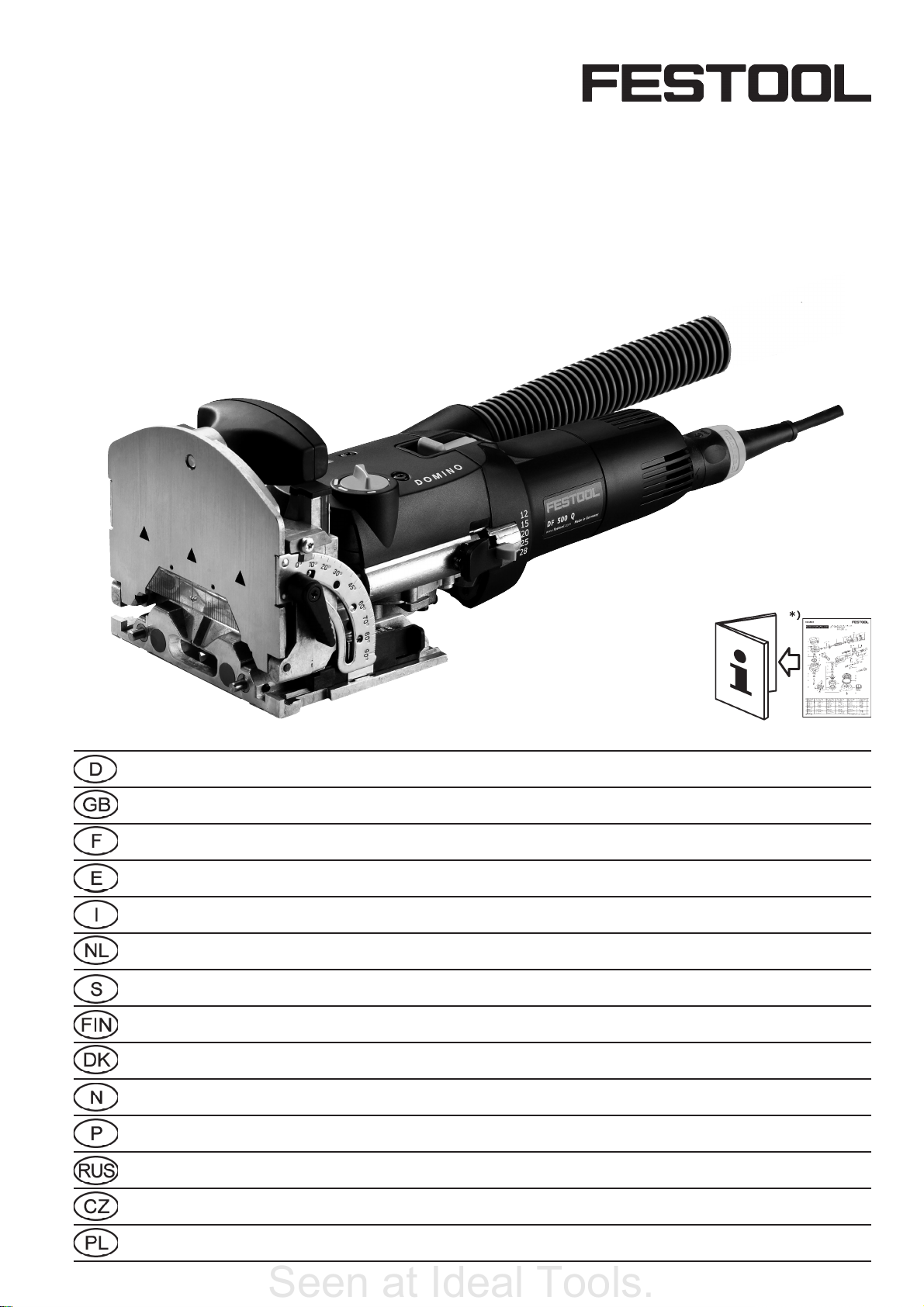
DOMINO
DF 500 Q
Bedienungsanleitung/Ersatzteilliste*) 5 - 8
Operating Instructions/Spare parts list*) 9 - 12
Mode d’emploi/Liste de pièces de rechange*) 13 - 16
Instrucciones de servicio/Lista de piezas de repuesto*) 17 - 21
Istruzioni d’uso/Elenco parti di ricambio*) 22 - 25
Gebruiksaanwijzing/Lijst met reserveonderdelen*) 26 - 29
Bruksanvisning/Reservdelslista*) 30 - 33
Käyttöohje/Varaosaluettelo*) 34 - 37
Driftsvejledning/Reservedelsliste*) 38 - 41
Bruksanvisning/Reservedelsliste*) 42 - 45
Instruções de uso/Lista de peças sobresselentes*) 46 - 49
Руководство по эксплуатации/Перечень запасных частей*) 50 - 54
Návod k obsluze/Seznam náhradních dílù*) 55 - 58
468 063_006
Instrukcja obs³ug/Lista czêœci zamiennych*) 59 - 63
Page 2
1.11.3 1.21.4
Seen at Ideal Tools.
1
2.1
12
15
20
25
28
1.8
1.7
80°
70°
60°
45°
30°
20°
10°
0°
40
36
28
1.6
1.5
2
2.2
2.3
2.4
3
Page 3
Seen at Ideal Tools.
Page 4

Seen at Ideal Tools.
Page 5
Table of contents
Seen at Ideal Tools.
1 Introduction
2 Technical data
3 Pictograms
4 Intended use
5 Safety instructions
5.1 General Safety Rules
5.2 Tool-specifi c safety rules
5.3 Noise and vibration information
6 Control elements
7 Power supply and start-up
8 Machine settings
8.1 Changing tools
8.2 Adjusting the milling depth
8.3 Setting jointing height
8.4 Setting angle guide
8.5 Setting dowel-hole width
8.6 Dust extraction
8.7 Support
9 Working with the machine
10 Maintenance and care
11 Accessories, tools
12 Warranty
13 Example applications
14 Fault correction
The specifi ed illustrations can be found at the
beginning of the operating instructions.
1 Introduction
Thank you very much for purchasing the Domino Dowel Jointer DF 500 Q from Festool.
Please observe the information in these Operating Instructions and the enclosed documents.
They are for your own safety and to help prevent damage to the machine.
5 Safety instructions
It is essential that you observe the
following safety information. Nonobservance can result in electric shock, fi re
and/or serious injuries.
5.1 General Safety Rules
Before using the machine, read the
enclosed safety instructions and these
operating instructions carefully and
thoroughly.
Save all enclosed documents and pass the machine with all these documents only.
5.2 Tool-specifi c safety rules
- The tools must be designed for the speed
specifi ed on the power tool at a minimum.
Tools running at overspeeds can fl y apart and
cause injury.
- Use the machine only with the guide frame
mounted. The guide frame protects the user
against broken-off parts of the jointer bit and
accidental contact with the jointer bit.
- The DF 500 Q must only be fi tted with the
jointer bits offered by Festool for this purpose.
The use of other jointer bits is prohibited due
to the increased risk of injury.
- Never work with blunt or damaged jointer
bits. Blunt or damaged jointer bits can lead
to a loss of control of the power tool.
- When the motor unit is released, it must
move back actuated by spring force so that
the jointer bit disappears completely in the
protective cover. If this does not happen, the
machine must be switched off immediately
and repaired before reuse.
2 Technical data
Power 420 W
Speed (no load) 25 500 rpm
Jointing depth, max. 28 mm
Jointing width, max. 23 mm + jointer bit
diameter
Jointing bit diameter, max. 10 mm
Connecting thread of drive shaft M6 x 0.75
Weight (excluding cable) 3.2 kg
Degree of protection
3 Pictograms
Note, Danger!
4 Intended use
The Domino dowel jointer is designed to produce Domino dowelled joints in soft and hard
wood, chip board, plywood and fi bre boards.
All applications beyond this are regarded as
unspecifi ed use.
The Domino dowel jointer is designed and
approved for use by trained persons or specialists.
The user is liable for damage and injury
resulting from incorrect usage!
5.3 Noise and vibration information
The typical values determined in accordance
with EN 60745 are:
Sound-pressure level 84 dB(A)
Sound-power level 95 dB(A)
Measuring uncertainty allowance K = 4 dB
Measured acceleration 6.8 m/s²
Wear ear protection!
/ II
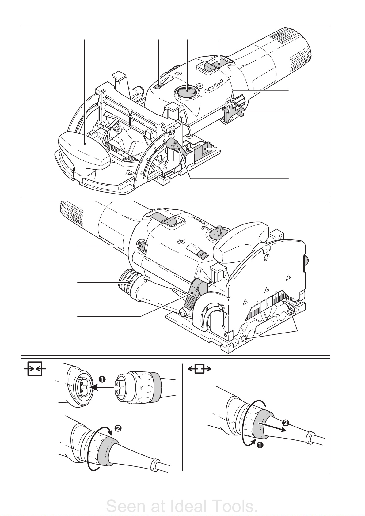
6 Control elements
(1.1) ON/OFF switch
(1.2) Rotary switch for Domino dowel-hole
width
(1.3) Unlocking device for motor unit / guide
frame
(1.4) Auxiliary handle
(1.5) Clamping lever for angle guide
(1.6) Selection slide for material thickness
(1.7) Notch lever for Domino dowel-hole
depth
(1.8) Notch lever lock
(2.1) Spindle lock
(2.2) Extraction nozzle
(2.3) Clamping lever for jointing height ad-
justment
(2.4) Stop pins
9
Page 6

7 Power supply and start-up
Seen at Ideal Tools.
The mains voltage must correspond to
the specifi cation on the rating plate.
Always switch the machine off before
connecting or disconnecting the mains
lead!
See Fig. 2 for connection and disconnection of
the power cable.
To switch on, push the switch (1.1) forwards
until it engages. Pressing the back end of the
switch is suffi cient to release the switch-on lock
and switch the machine off.
8 Machine settings
Always remove the power supply plug
from the socket before carrying out any
work on the machine.
8.1 Changing tools
Required tools: fork wrench a/f 8 (supplied).
Always wear protective gloves during tool
change due to the risk of injury from the sharp
tool cutters.
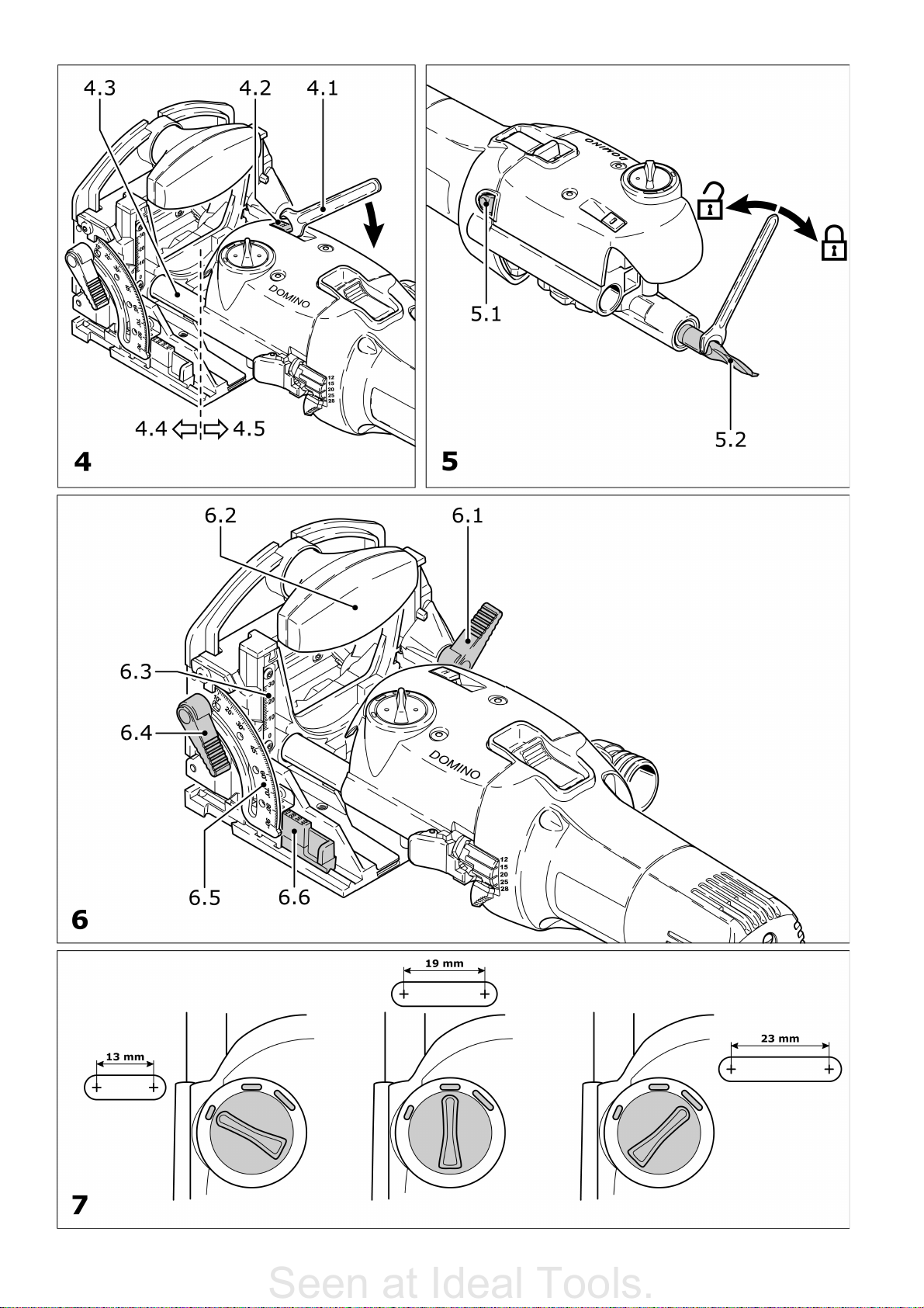
8.3 Setting jointing height
a) with selection slide
- Release the clamping lever (6.1) for jointing
height adjustment.
- Using the additional handle (6.2), raise the
front section of the guide frame.
- Use the slide (6.6) to set the desired board
thickness (16 mm, 19 mm, 22 mm, 25 mm,
28 mm, 36 mm, 40 mm).
- Press the front section of the guide frame
downwards as far as the stop.
- Close the clamping lever (6.1).
b) freely selectable
- Release the clamping lever (6.1) for jointing
height adjustment.
- Using the additional handle (6.2), raise the
front section of the guide frame.
- Push the slide (6.6) to the stop in direction
motor unit.
- Set the desired jointing height using the scale
(6.3) by moving the front section of the guide
frame vertically.
- Close the clamping lever (6.1).
a) Removing the tool
- Lift the unlocking lever (4.2) until it audibly
engages with the fork wrench (4.1).
- Separate the motor unit (4.5) and the guide
frame (4.4).
- Press and hold in the spindle lock (5.1).
- Release and unscrew the jointer bit (5.2) with
the fork wrench.
- Release the spindle lock.
b) Inserting the tool
- Before inserting a new jointer bit, ensure that
the machine, the guide frame and the guides
(4.3) are clean. Remove any contamination
that may be present. Only use sharp, undamaged and clean tools.
- Press and hold in the spindle lock (5.1).
- Use the fork wrench to screw on the jointer
bit (5.2).
- Release the spindle lock.
- Slide the guide frame onto the motor unit until
it audibly engages.
8.2 Adjusting the milling depth
- Open the notch lever lock (1.8) by pressing
it.
- Use the locking lever (1.7) to set the desired
jointing depth (12 mm, 15 mm, 20 mm, 25
mm, 28 mm). For the jointer bit with a diameter of 5 mm, only jointing depths of 12 mm,
15 mm and 20 mm are permitted due to its
short shank length.
- Release the notch lever lock again.
Ensure that the jointing depth is at
least 3 mm smaller than the workpiece
thickness. Otherwise the jointer bit can
emerge from the workpiece at the rear
side, which involves an increased risk
of injury.
8.4 Setting angle guide
- Release the clamping lever for the angle guide
(6.4).
- Set the desired angle: using the scale (6.5)
steplessly from 0° - 90°, or in notches at 0°,
22.5°, 45°, 67.5°, 90°.
- Close the clamping lever (6.4).
8.5 Setting dowel-hole width
Reliable setting of the dowel-hole width
with the rotary switch (1.2) is only pos-
sible with the machine running!
The following dowel-hole settings are possible
(image 7):
13 mm + jointer bit diameter
19 mm + jointer bit diameter
23 mm + jointer bit diameter
8.6 Dust extraction
Always connect the machine to a dust
extractor. You can connect a Festool ex-
tractor with an extractor hose diameter
of 27 mm to the extractor connector
(2.2).
8.7 Support
The support (8.1) can be used to enlarge the
contact area during jointing at the workpiece
edge, thus allowing safer guidance of the machine.
Secure the support with both screws (8.2) to
the threaded bores (8.3) of the guide frame,
whereby the contact areas of the support ring
(8.5) and the table (8.4) must be on the same
plane.
10
Page 7

9 Working with the machine
Seen at Ideal Tools.
Prior to processing the fi nal workpiece, it is advisable to optimise the dowel-hole depth, width
and diameter using a sample workpiece.
Please observe the following rules
when working:
- Always secure the workpiece in such a manner
that it cannot move while being sawed.
- Always hold the Domino dowel jointer with
both hands at the motor housing and at the
additional handle. This reduces the risk of
injury and is a prerequisite for precise work.
- Close the clamping lever for jointing height
adjustment (2.3) and the clamping lever for
the angle guide (1.5) so that accidental release during operation is impossible.
- Adapt the feed rate to the jointer bit diameter and material. Work with a constant feed
rate.
- Only lay the Domino dowel jointer aside when
the jointer bit has come to a complete standstill.
10 Maintenance and care
Always remove the power supply plug
from the socket before carrying out any
work on the machine.
All maintenance and repair work which
requires the motor casing to be opened
may only be carried out by an authori-
sed service centre.
The Domino dowel jointer is to a large extent
maintenance-free. However, we recommend an
annual inspection and/or a check after approx.
100 operating hours at an authorised customer
service workshop. This is for the safety of the
user and the value stability of the Domino dowel jointer.
Always keep the machine and the ventilation
slots clean.
Dust deposits must be removed from the guides
(4.3). Oil the guides regularly and lightly with
resin-free oil (e.g. sewing machine oil).
The tool is fi tted with special motor brushes
with an automatic cut-out. When the brushes
become worn the power supply is shut off automatically and the tool comes to a standstill.
Procedure
Proceed as follows to create a dowelled joint:
- Select a Domino dowel and insert a matching
jointing bit in the Domino dowel jointer (Chap.
8.1).
- Set the jointing depth (Chap. 8.2). The jointing depth must be at least 3 mm smaller than
the workpiece thickness so that the dowelled
joint is supportable.
- Set the jointing height to correspond to the
workpiece thickness (Chap. 8.3).
- Mark the areas on the workpiece that belong
together (10.1) so that you will be able to join
them correctly again once you have cut the
dowel holes.
- Position the two workpieces to be joined
against one another and mark the desired
positions of the dowels with a pencil (10.2).
- Set the desired dowel-hole width (Chap. 8.5).
Our recommendation: Cut the fi rst hole
without play (dowel-hole width = Domino
dowel width), and the remaining dowel holes
to the next largest dowel-hole width (image
10). The fi rst dowel hole therefore serves as a
reference dimension, whereas the remaining
dowel holes have tolerance for manufacturing
inaccuracies.
- Cut the dowel holes:
a) the fi rst dowel hole by placing the stop pin
at the side edge of the workpiece,
b) the following dowel holes according to the
pencil markings made beforehand and the
scale of the viewing window (10.3).
11 Accessories, tools
For your own safety, use only original
Festool accessories and spare parts.
The accessory and tool order number can be
found in the Festool catalogue or on the Internet
under “www.festool.com”.
12 Warranty
Our equipment is under warranty for at least 12
months with regard to material or production
faults in accordance with national legislation.
In the EU countries, the warranty period is 24
months (an invoice or delivery note is required
as proof of purchase).
Damage resulting from, in particular, normal
wear and tear, o-verloading, improper handling,
or caused by the user or other damage caused
by not following the operating instructions, or
any fault acknowledged at the time of purchase,
is not covered by the warranty. Complaints will
only be acknowledged if the equipment has not
been dismantled before being sent back to the
suppliers or to an authorised Festool customer
support workshop.
Store the operating instructions, safety notes,
spare parts list and proof of purchase in a safe
place. In addition, the manufacturer’s current
warranty conditions apply.
Note
We reserve the right to make changes to the
technical data contained in this information as
a result of ongoing research and development
work.
11
Page 8

13 Example applications
Seen at Ideal Tools.
(The following images A1 to A6.3 are on a separate enclosed sheet).
A1.1 - A1.4 Stable and non-twisting mitred frame joint.
A2 Very stable block frame joint.
A3 Very stable and non-twisting wood joints in frame and chair construction.
A4.1 - A4.3 Stable, non-twisting and precisely fi tting board joint (mitred).
A5.1 Stable and precisely fi tting board joint (butted).
A5.2 Setting the Domino dowel jointer for board joint (butted), end face dowel hole.
A5.3 Setting the Domino dowel jointer with angle bracket for board joint (butted).
A6.1 Stable and precisely fi tting board joint (centred).
A6.2 Setting the Domino dowel jointer for board joint (centred).
A6.3 Setting the Domino dowel jointer for board joint (centred), end face dowel
hole.
14 Fault correction
(The following images B1 to B6 are on a separate enclosed sheet).
Fault Cause Adjustment
B1 burns blunt jointer bit use sharp jointer bit
B2 expansion of dowel
hole
B3 dowel penetrates work-
piece
B4 Tears at edge of dowel
hole
B5 dowel hole not parallel
to workpiece edge
B6 dowel hole not at right
angles (90°) to workpiece surface
The position of the dowel holes, which were
created with the left
and right stop pin,
does not exactly match
(different distance to
workpiece edge).
jointing depth excessive (greater than 20 mm) with 5 mm
jointing bit
incorrect workpiece thickness
and/or jointing depth
excessive feed rate reduce feed rate
workpiece has shifted during
processing
a) deposits (e.g. chips) below
the base plate
b) angle guide not set exactly
to 90°
c) worked on without angle
bracket
The midpoint between the two
stop pins is not exactly in the
midpoint of the swivel range of
the jointer bit.
reduce jointing depth
adapt workpiece thickness and/
or jointing depth
secure workpiece properly
a) remove deposits
b) set angle guide to 90° exact-
ly
c) use angle bracket
Turn the eccentric (9.1) with a
screwdriver (clockwise or anticlockwise) until the position
of the dowel holes matches for
both stop pins.
12
Page 9

EG-Konformitätserklärung. Wir erklären in alleini-
Seen at Ideal Tools.
ger Verantwortung, dass dieses Produkt mit den
folgenden Normen oder normativen Dokumenten
übereinstimmt:
EN 60 745, EN 55 014, EN 61 000 gemäß den Bestimmungen
der Richtlinien 98/37/EG, 89/336/EWG.
CE-Konformitetserklæring. Vi erklærer på eget ansvar
at dette produktet er i overensstemmelse med følgen-
de normer eller normative dokumenter: EN 60 745,
EN 55 014, EN 61 000 i henhold til bestemmelsene i direktivene 98/37/EF, 89/336/EØF.
EC-Declaration of Conformity: We declare at our
sole responsibility that this product is in conformity
with the following standards or standardised docu-
ments:
EN 60 745, EN 55 014, EN 61 000 in accordance with the
regulations 98/37/EC, 89/336/EEC.
CE-Déclaration de conformité communautaire. Nous
déclarons sous notre propre responsabilité que ce
produit est conforme aux normes ou documents de
normalisation suivants: EN 60 745, EN 55 014, EN 61 000
conformément aux prescriptions des directives 98/37/CE,
89/336/CEE.
CE-Declaración de conformidad. Declaramos bajo
nuestra exclusiva responsabilidad que este producto
corresponde a las siguientes normas o documentos
normalizados: EN 60 745, EN 55 014, EN 61 000 conforme
a las prescripciones estipuladas en las directrices 98/37/CE,
89/336/CEE.
CE-Dichiarazione di conformità. Dichiariamo sotto la
nostra esclusiva responsabilità che il presente pro-
dotto è conforme alle norme e ai documenti normativi seguenti: EN 60 745, EN 55 014, EN 61 000 conformemente
alle normative delle direttive 98/37/CE, 89/336/CEE.
CE-Declaração de conformidade: Declaramos, sob
a nossa exclusiva responsabilidade, que este produto corresponde às normas ou aos documentos
normativos citados a seguir:
EN 60 745, EN 55 014, EN 61 000 segundo as disposições
das directivas 98/37/CE, 89/336/CEE.
Заявление о конформности СЕ. Мы заявляем
в единоличной ответственности, что данное
изделие соответствует требованиям следующих
стандартов или нормативов: EN 60 745, EN 55 014, EN
61 000 в соответствии с постановлениями директив ЕС
98/37, ЕЭС 89/336.
Prohlášení o souladu s normami CE. Prohlašujeme na
vlastní zodpovìdnost, že tento výrobek odpovídá nás-
ledujícím normám nebo normativním dokumentùm:
EN 60 745, EN 55 014, EN 61 000 v souladu s ustanoveními
smìrnic 98/37/EHS, 89/336/EHS.
Oœwiadczenie o zgodnoœci CE. Niniejszym oœwi-
adczamy z ca³¹ odpowiedzialnoœci¹, ¿e wyrób
ten odpowiada nastêpuj¹cym normom wzglêdnie
dokumentom normatywnym: EN 60 745, EN 55 014, EN
61 000 zgodnie z postanowieniami wytycznych 98/37/EG,
89/336/EWG.
EG-conformiteitsverklaring. Wij verklaren op eigen verantwoordelijkheid dat dit produkt voldoet aan de vol-
gende normen of normatieve documenten. EN 60 745,
EN 55 014, EN 61 000 conform de richtlijnen 98/37/EG,
89/336/EEG.
EG-konformitetsförklaring. Vi förklarar i eget ansvar,
att denna produkt stämmer överens med följande nor-
mer och normativa dokument: EN 60 745, EN 55 014,
EN 61 000 enligt bestämmelserna i direktiven 98/37/EG,
89/336/EEG.
EY-standardinmukaisuusvakuutus. Vakuutamme yk-
sinvastuullisina, että tuote on seuraavien standardien
ja normatiivisten ohjeiden mukainen: EN 60 745, EN 55 014,
EN 61 000 direktiivien 98/37/EY, 89/336/EY määräysten
mukaan.
EF-konformitetserklæring: Vi erklærer at have alene
ansvaret for, at dette produkt er i overensstem-
melse med de følgende normer eller normative
dokumenter:
EN 60 745, EN 55 014, EN 61 000 i henhold til bestemmelserne af direktiverne 98/37/EF, 89/336/EØF.
Leiter Forschung und Entwicklung
Manager Research and Development
Directeur de recherce et développement
Festool GmbH
Wertstr. 20
D-73240 Wendlingen
Dr. Johannes Steimel
455 789/II/200405
 Loading...