

Page 1
1
470 339_002
Manual de instrucciones
Página 14 - 19
IMPORTANTE: Lea y comprende todas las
instrucciones antes de usar.
Guide d’utilisation
Page 8 - 13
IMPORTANT: Lire et comprendre toutes les
instructions avant de démarrer les travaux.
Instruction manual
Page 2 - 7
IMPORTANT: Read and understand all instructions
before using.
DOMINO
DF 500
Page 2

2
alcohol or medication. A moment of inattention while operating power tools may result in serious personal injury.
b) Use safety equipment. Always wear eye protection.
Safety equipment such as dust mask, non-skid safety shoes,
hard hat, or hearing protection used for appropriate conditions
will reduce personal injuries.
c) Avoid accidental starting. Ensure the switch is in the
off position before plugging in. Carrying power tools with
your fi nger on the switch or plugging in power tools that have
the switch on invites accidents.
d) Remove any adjusting key or wrench before turning
the power tool on. A wrench or a key left attached to a rotat-
ing part of the power tool may result in personal injury.
e) Do not overreach. Keep proper footing and balance
at all times. This enables better control of the power tool in
unexpected situations.
f) Dress properly. Do not wear loose clothing or jewellery. Keep your hair, clothing and gloves away from
moving parts. Loose clothes, jewellery or long hair can be
caught in moving parts.
g) If devices are provided for the connection of dust
extraction and collection facilities, ensure these are connected and properly used. Use of these devices can reduce
dust related hazards.
4) Tool use and care
a) Do not force the power tool. Use the correct power
tool for your application. The correct power tool will do the
job better and safer at the rate for which it was designed.
b) Do not use the power tool if the switch does not turn
it on and off. Any power tool that cannot be controlled with
the switch is dangerous and must be repaired.
c) Disconnect the plug from the power source before
making any adjustments, changing accessories, or storing power tools. Such preventive safety measures reduce the
risk of starting the power tool accidentally.
d) Store idle power tools out of the reach of children and
do not allow persons unfamiliar with the power tool or
these instructions to operate the power tool. Power tools
are dangerous in the hands of untrained users.
e) Maintain power tools. Check for misalignment or binding of moving parts, breakage of parts and any other
condition that may affect the power tools operation. If
damaged, have the power tool repaired before use. Many
accidents are caused by poorly maintained power tools.
f) Keep cutting tools sharp and clean. Properly maintained
cutting tools with sharp cutting edges are less likely to bind
and are easier to control.
g) Use the power tool, accessories and tool bits etc., in
accordance with these instructions and in the manner
intended for the particular type of power tool, taking
into account the working conditions and the work to be
performed. Use of the power tool for operations different from
those intended could result in a hazardous situation.
5) Service
a) Have your power tool serviced by a qualifi ed repair
person using only identical replacement parts. This will
ensure that the safety of the power tool is maintained.
Specifi c Safety Rules
a) The tools must be designed for the speed specifi ed on
the power tool at a minimum. Tools running at overspeeds
can fl y apart and cause injury.
b) Use the machine only with the guide frame mounted.
The guide frame protects the user against broken-off parts of
the jointer bit and accidental contact with the jointer bit.
c) The DF 500 Q must only be fi tted with the jointer bits
offered by Festool for this purpose. The use of other jointer
bits is prohibited due to the increased risk of injury.
d) Never work with blunt or damaged jointer bits. Blunt
or damaged jointer bits can lead to a loss of control of the
power tool.
General safety rules
Read and understand all instructions. Failure to follow all instructions listed below may result in
electric shock, fi re and/or serious personal injury.
SAVE THESE INSTRUCTIONS
1) Work area safety
a) Keep work area clean and well lit. Cluttered and dark
areas invite accidents.
b) Do not operate power tools in explosive atmospheres,
such as in the presence of fl ammable liquids, gases or
dust. Power tools create sparks which may ignite the dust or
fumes.
c) Keep children and bystanders away while operating a
power tool. Distractions can cause you to lose control.
2) Electrical safety
a) Power tool plugs must match the outlet. Never modify
the plug in any way. Do not use any adapter plugs with
earthed (grounded) power tools. Unmodifi ed plugs and
matching outlets will reduce risk of electric shock.
b) Avoid body contact with earthed or grounded surfaces
such as pipes, radiators, ranges and refrigerators. There
is an increased risk of electric shock if your body is earthed
or grounded.
c) Do not expose power tools to rain or wet conditions.
Water entering a power tool will increase the risk of electric
shock.
d) Do not abuse the cord. Never use the cord for carrying,
pulling or unplugging the power tool. Keep cord away
from heat, oil, sharp edges or moving parts. Damaged or
entangled cords increase the risk of electric shock.
e) When operating a power tool outdoors, use an extension cord suitable for outdoor use. Use of a cord suitable
for outdoor use reduces the risk of electric shock.
3) Personal safety
a) Stay alert, watch what you are doing and use common
sense when operating a power tool. Do not use a power
tool while you are tired or under the infl uence of drugs,
Table of contents
General safety rules 2
Specifi c Safety Rules 2
Health hazard by dust 3
Technical data 3
Symbols 3
Use for intended purpose 3
Control elements 3
Power supply and start-up 3
Extension cable 4
Tool settings 4
Changing tools 4
Adjusting the milling depth 4
Setting jointing height 4
Setting angle guide 4
Setting dowel-hole width 4
Dust extraction 5
Support 5
Working with the machine 5
Example applications 5
Systainer 6
Maintenance and care 6
Accessories, tools 6
Warranty 6
Fault correction 7
Page 3
3
e) When the motor unit is released, it must move back
actuated by spring force so that the jointer bit disappears completely in the protective cover. If this does not
happen, the machine must be switched off immediately and
repaired before reuse.
Health hazard by dust
Various dust created by power sanding, sawing,
grinding, drilling and other construction activities contains
chemicals known (to the State of California) to cause cancer,
birth defects or other reproductive harm. Some examples of
these chemicals are:
• lead from lead-based paints,
• crystalline silica from bricks and cement and other masonry
products, and
• arsenic and chromium from chemically-treated lumber.
The risk from these exposures varies, depending on how often
you do this type of work.
To reduce your exposure to these chemicals:
work in a well ventilated area, and work with
approved safety equipment, such as dust
masks that are specially designed to fi lter
out microscopic particles. Wash hands after
handling.
TO REDUCE THE RISK OF INJURY,
USER MUST READ AND UNDERSTAND INSTRUCTION MANUAL.
Technical data
Power 420 W
Speed (no load) 25 500 rpm
Jointing depth, max.: 28 mm
Jointing width, max.: 23 mm + jointer bit
diameter
Jointing bit diameter, max.: 10 mm
Connecting thread of drive shaft M6 x 0.75
Weight (excluding cable 3.2 kg
Degree of protection / II
Symbols
V Volts
A Amperes
Hz Hertz
~ Alternating current
n
0
No load speed
Class II Construction
rpm Revolutions or reciprocation per minute
Ø Diameter
Use for intended purpose
The Domino dowel jointer is designed to produce Domino
dowelled joints in soft and hard wood, chip board, plywood
and fi bre boards. All applications beyond this are regarded as
unspecifi ed use.
The Domino dowel jointer is designed and approved for use by
trained persons or specialists.
The user is liable for damage and injury resulting
from incorrect usage!
Control elements
60°
70°
80°
10°
0°
20°
30°
45°
40
36
28
12
15
20
25
28
1.11.21.31.4
1.8
1.6
1.7
1.5
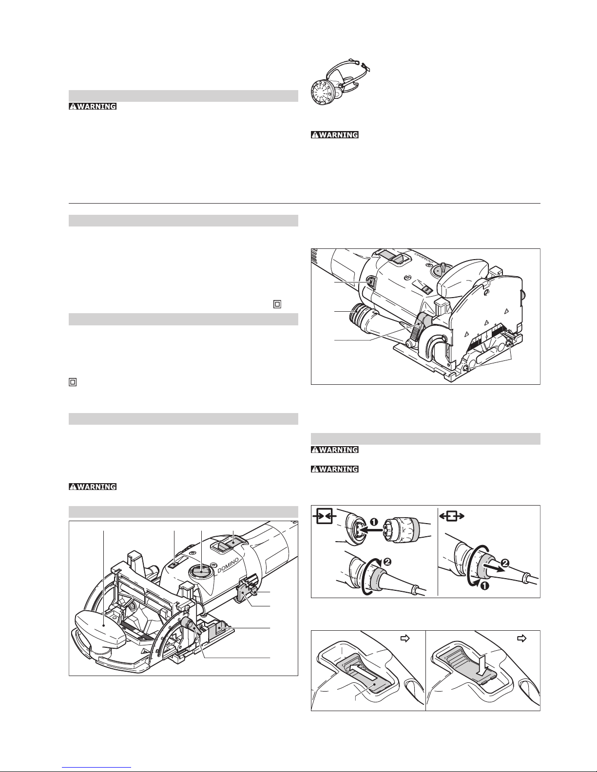
(1.1) ON/OFF switch
(1.2) Rotary switch for Domino dowel-hole width
(1.3) Unlocking device for motor unit / guide frame
(1.4) Auxiliary handle
(1.5) Clamping lever for angle guide
(1.6) Selection slide for material thickness
(1.7) Notch lever for Domino dowel-hole depth
(1.8) Notch lever lock
2.3
2.1
2.2
2.4
(2.1) Spindle lock
(2.2) Extraction nozzle
(2.3) Clamping lever for jointing height adjustment
(2.4) Stop pins
Power supply and start-up
The mains voltage must correspond to the speci-
fi cation on the rating plate.
Always switch the machine off before connecting
or disconnecting the mains lead!
See Fig. 3 for connection and disconnection of the power
cable.
3
To switch on, push the switch (4.1) forwards until it engages.
Pressing the back end of the switch is suffi cient to release the
switch-on lock and switch the machine off.
4.1
0 I I O
Page 4
4
Extension cable
If an extension cable is required, it must have a suffi cient
cross-section so as to prevent an excessive drop in voltage or
overheating. An excessive drop in voltage reduces the output
and can lead to failure of the motor. The table shows you the
correct cable diameter as a function of the cable length for
the DF 500 Q.
Total extension cord lenght (feed) 25 50 100 150
Cord size (AWG) 18161614
Use only U.L. and CSA listed extension cables. Never use two
extension cables together. Instead, use one long one.
Note: The lower the AWG number, the stronger the cable.
Tool settings
Always remove the power supply plug from the
socket before carrying out any work on the machine.
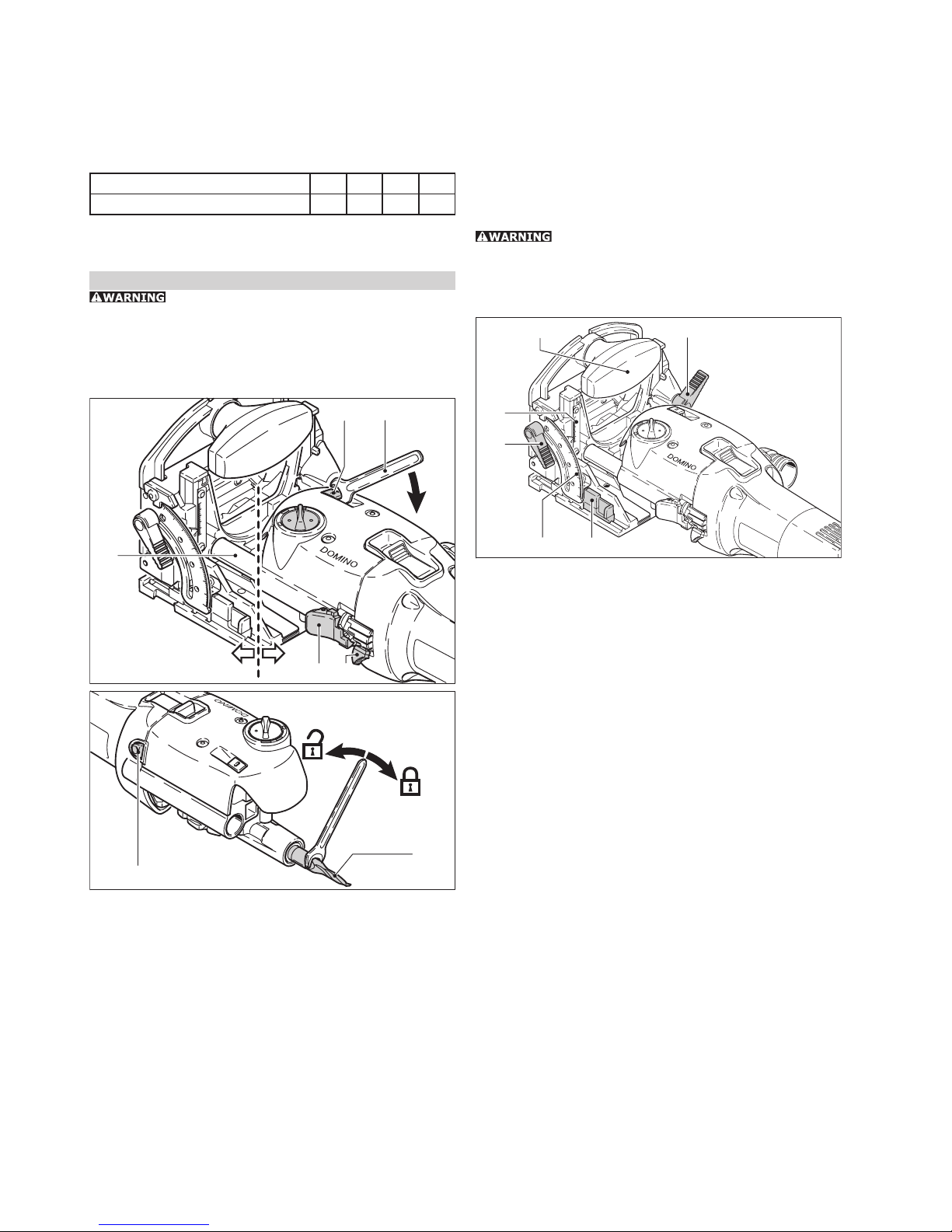
Changing tools
Required tools: fork wrench a/f 8 (supplied)
Always wear protective gloves during tool change due to the
risk of injury from the sharp tool cutters.
20°
30°
45°
60°
70°
80°
90°
10°
30
20
10
0
40
36
28
12
15
20
25
28
5.6
5.1
5.3
5.2
5.7
5.4 5.5
6.1
6.2
a) Removing the tool
- Lift the unlocking lever (5.2) until it audibly engages with
the fork wrench (5.1).
- Separate the motor unit (5.5) and the guide frame (5.4).
- Press and hold in the spindle lock (6.1).
- Release and unscrew the jointer bit (6.2) with the fork
wrench.
- Release the spindle lock.
b) Inserting the tool
- Before inserting a new jointer bit, ensure that the machine,
the guide frame and the guides (5.3) are clean. Remove any
contamination that may be present. Only use sharp, undamaged and clean tools.
- Press and hold in the spindle lock (6.1).
- Use the fork wrench to screw on the jointer bit (6.2).
- Release the spindle lock.
- Slide the guide frame onto the motor unit until it audibly
engages.
Adjusting the milling depth
- Open the notch lever lock (5.7) by pressing it.
- Use the locking lever (5.6) to set the desired jointing depth
(12 mm, 15 mm, 20 mm, 25 mm, 28 mm). For the jointer
bit with a diameter of 5 mm, only jointing depths of 12 mm,
15 mm and 20 mm are permitted due to its short shank
length.
- Release the notch lever lock again.
Ensure that the jointing depth is at least 3 mm
smaller than the workpiece thickness. Otherwise the jointer bit
can emerge from the workpiece at the rear side, which involves
an increased risk of injury.
Setting jointing height
20°
30°
45°
60°
70°
80°
90°
10°
30
20
10
0
40
36
28
12
15
20
25
28
7.6
7.1
7.2
7.5
7.3
7.4
a) with selection slide
- Release the clamping lever (7.1) for jointing height adjust-
ment.
- Using the additional handle (7.2), raise the front section of
the guide frame.
- Use the slide (7.6) to set the desired board thickness (16
mm, 19 mm, 22 mm, 25 mm, 28 mm, 36 mm, 40 mm).
- Press the front section of the guide frame downwards as far
as the stop.
Close the clamping lever (7.1).
b) freely selectable
- Release the clamping lever (7.1) for jointing height adjust-
ment.
- Using the additional handle (7.2), raise the front section of
the guide frame.
- Push the slide (7.6) to the stop in direction motor unit.
- et the desired jointing height using the scale (7.3) by moving
the front section of the guide frame vertically.
- Close the clamping lever (7.1).
Setting angle guide
- Release the clamping lever for the angle guide (7.4).
- et the desired angle: using the scale (7.5) steplessly from
0° - 90°, or in notches at 0°, 22.5°, 45°, 67.5°, 90°.
- Close the clamping lever (6.4).
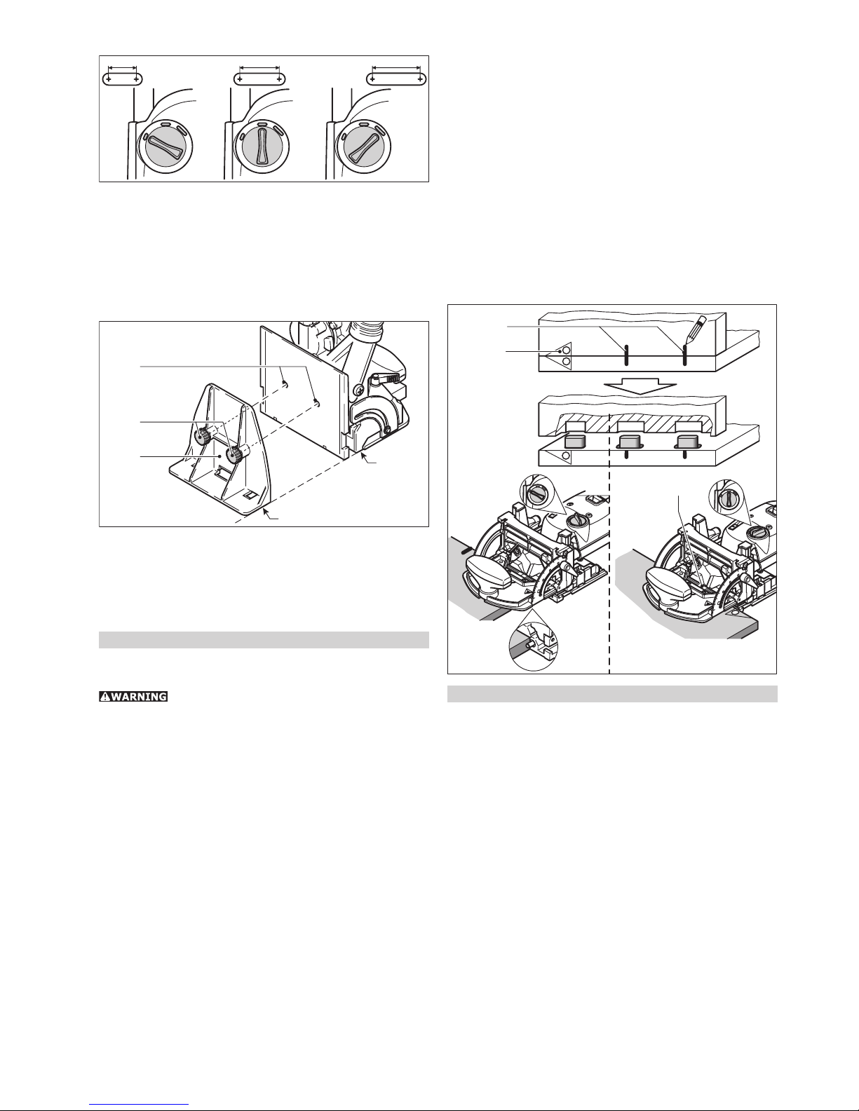
Setting dowel-hole width
Reliable setting of the dowel-hole width with the rotary switch
(1.2) is only possible with the machine running!
The following dowel-hole settings are possible (Fig. 8):
Page 5
5
13 mm
19 mm
23 mm
8
• 13 mm + jointer bit diameter
• 19 mm + jointer bit diameter
• 23 mm + jointer bit diameter
Dust extraction
Always connect the machine to a dust extractor.
You can connect a Festool extractor with an extractor hose
diameter of 27 mm to the extractor connector (2.2).
Support
9.3
9.2
9.5
9.4
9.1
The support (9.1) can be used to enlarge the contact area during jointing at the workpiece edge, thus allowing safer guidance
of the machine.
Secure the support with both screws (9.2) to the threaded
bores (9.3) of the guide frame, whereby the contact areas
of the support ring (9.5) and the table (9.4) must be on the
same plane.
Working with the machine
Prior to processing the fi nal workpiece, it is advisable to optimise the dowel-hole depth, width and diameter using a sample
workpiece.
Please observe the following rules when work-
ing:
• Always secure the workpiece in such a manner that it cannot
move while being sawed.
• Always hold the Domino dowel jointer with both hands at the
motor housing and at the additional handle. This reduces the
risk of injury and is a prerequisite for precise work.
• Close the clamping lever for jointing height adjustment (2.3)
and the clamping lever for the angle guide (1.5) so that accidental release during operation is impossible.
• Adapt the feed rate to the jointer bit diameter and material.
Work with a constant feed rate.
• Only lay the Domino dowel jointer aside when the jointer bit
has come to a complete standstill.
Procedure
Proceed as follows to create a dowelled joint:
- Select a Domino dowel and insert a matching jointing bit in
the Domino dowel jointer.
- Set the jointing depth. The jointing depth must be at least 3
mm smaller than the workpiece thickness so that the dowelled
joint is supportable.
- Set the jointing height to correspond to the workpiece thickness.
- Mark the areas on the workpiece that belong together (10.1)
so that you will be able to join them correctly again once you
have cut the dowel holes.
- Position the two workpieces to be joined against one another
and mark the desired positions of the dowels with a pencil
(10.2).
- Set the desired dowel-hole width. Our recommendation: Cut
the fi rst hole without play (dowel-hole width = Domino dowel
width), and the remaining dowel holes to the next largest
dowel-hole width (image 10). The fi rst dowel hole therefore
serves as a reference dimension, whereas the remaining
dowel holes have tolerance for manufacturing inaccuracies.
- Cut the dowel holes:
a) the fi rst dowel hole by placing the stop pin at the side
edge of the workpiece,
b) the following dowel holes according to the pencil mark-
ings made beforehand and the scale of the viewing window
(10.3).
10.2
10.1
10.3
1
1
1
1
Example applications
The following images A1 to A6.3 are on a separate enclosed
sheet.
A1.1 - A1.4: Stable and non-twisting mitred frame joint.
A2: Very stable block frame joint.
A3: Very stable and non-twisting wood joints in frame and
chair construction.
A4.1 - A4.3: Stable, non-twisting and precisely fi tting board
joint (mitred).
A5.1: Stable and precisely fi tting board joint (butted).
A5.2: Setting the Domino dowel jointer for board joint (butted),
end face dowel hole.
A5.3: Setting the Domino dowel jointer with angle bracket for
board joint (butted).
A6.1: Stable and precisely fi tting board joint (centred).
A6.2: Setting the Domino dowel jointer for board joint (cen-
tred).
A6.3: Setting the Domino dowel jointer for board joint (cen-
tred), end face dowel hole.
Page 6
6
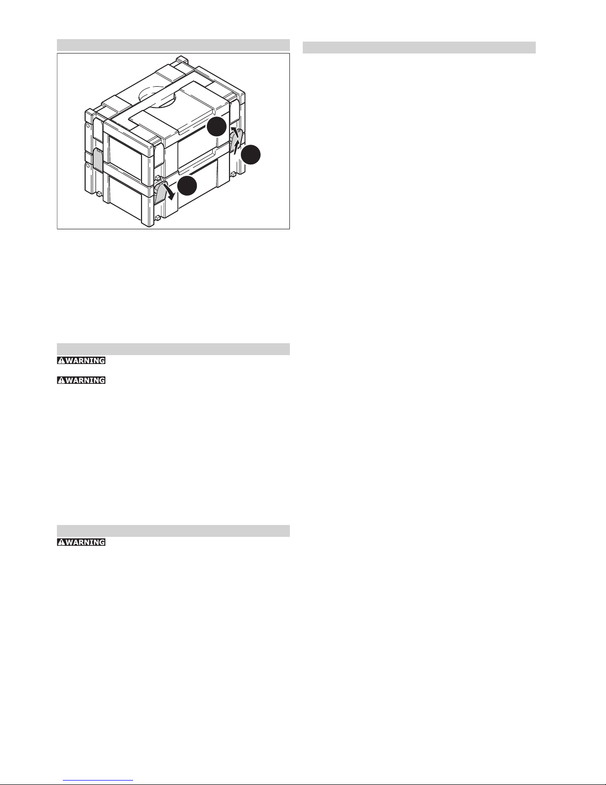
Systainer
11.3
11.2
11.1
Many Festool products are shipped in a unique system container,
called "Systainer". This provides protection and storage for the
tool and accessories. The Systainers are stackable and can be
interlocked together. They also can be interlocked atop Festool
CT dust extractors.
- Place one systainer on top of the other.
- Release all four latches on the lower systainer by pulling back
at their top edges (11.1).
- Slide all four latches upward (11.2).
- Snap all four latches back to their fl at position (11.3) so they
engage the stacking tabs of the upper systainer.
Maintenance and care
Always remove the power supply plug from the
socket before carrying out any work on the machine.
All maintenance and repair work which requires
the motor casing to be opened may only be carried out by an
authorised service centre.
The Domino dowel jointer is to a large extent maintenance-free.
However, we recommend an annual inspection and/or a check
after approx. 100 operating hours at an authorised customer
service workshop. This is for the safety of the user and the
value stability of the Domino dowel jointer.
Always keep the machine and the ventilation slots clean.
Dust deposits must be removed from the guides (4.3). Oil the
guides regularly and lightly with resin-free oil (e.g. sewing
machine oil).
The tool is fi tted with special motor brushes with an automatic
cut-out. When the brushes become worn the power supply is
shut off automatically and the tool comes to a standstill.
Accessories, tools
For your own safety, use only original Festool
accessories and spare parts.
The accessory and tool order number can be found in the Festool
catalogue or on the Internet under www.festool-usa.com.
Warranty
Conditions of 1+2 Warranty
You are entitled to a free extended warranty (1 year + 2 years
= 3 years) for your Festool power tool. Festool shall be responsible for all shipping costs during the fi rst year of the warranty.
During the second and third year of the warranty the customer
is responsible for shipping the tool to Festool. Festool will pay
for return shipping to the customer using UPS Ground Service.
All warranty service is valid 3 years from the date of purchase
on your receipt or invoice.
Festool Limited Warranty
This warranty is valid on the pre-condition that the tool is
used and operated in compliance with the Festool operating
instructions. Festool warrants, only to the original consumer
purchaser, that the specifi ed tool will be free from defects in
materials and workmanship for a term of one year from the
date of procurement. Festool makes no other warranty, express or implied, for Festool portable power tools. No agent,
representative, distributor, dealer or employee of Festool has
the authority to increase or otherwise change the obligations
or limitations of this warranty. The obligations of Festool in its
sole discretion under this warranty shall be limited to the repair
or replacement of any Festool portable power tool that is found
to be defective as packaged with the User Manual.
Excluded from coverage under this warranty are: normal wear
and tear; damages caused by misuse, abuse or neglect; damage caused by anything other than defects in material and
workmanship. This warranty does not apply to accessory items
such as circular saw blades, drill bits, router bits, jigsaw blades,
sanding belts, and grinding wheels. Also excluded are “wearing
parts”, such as carbon brushes, lamellas of air tools, rubber
collars and seals, sanding discs and pads, and batteries.
Festool portable power tools requiring replacement or repair
are to be returned with the receipt of purchase to Festool (call
800-554-8741 for address details).
IN NO EVENT SHALL FESTOOL BE LIABLE FOR ANY CONSEQUENTIAL OR INCIDENTAL DAMAGES FOR BREACH
OF THIS OR ANY OTHER WARRANTY, EXPRESSED OR
IMPLIED WHATSOEVER. ALL WARRANTIES IMPLIED BY
STATE LAW, INCLUDING THE IMPLIED WARRANTIES OF
MERCHANTABILITY AND FITNESS FOR A PARTICULAR
PURPOSE, ARE HEREBY LIMITED TO THE DURATION OF
THREE YEARS.
Some states in the U.S. and some Canadian provinces do not
allow the limitations on how long an implied warranty lasts, so
the above limitation may not apply to you. With the exception
of any warranties implied by state or province law as hereby
limited, the foregoing express limited warranty is exclusive
and in lieu of all other warranties, guarantees, agreements and
similar obligations of Festool.
This warranty gives you specifi c legal rights and you may also
have other rights which vary from state to state in the U.S.
and province to province in Canada.
Page 7

7
Fault correction
The following images B1 to B6 are on a separate enclosed sheet.
Fault Cause Adjustment
B1 burns blunt jointer bit use sharp jointer bit
B2 expansion of dowel hole jointing depth excessive (greater than
20 mm) with 5 mm jointing bit
reduce jointing depth
B3 dowel penetrates workpiece incorrect workpiece thickness and/or
jointing depth
adapt workpiece thickness and/or jointing
depth
B4 tears at edge of dowel hole excessive feed rate reduce feed rate
B5 dowel hole not parallel to
workpiece edge
workpiece has shifted during processing secure workpiece properly
B6 dowel hole not at right angles
(90°) to workpiece surface
a) deposits (e.g. chips) below the base
plate
b) angle guide not set exactly to 90°
c) worked on without angle bracket
a) remove deposits
b) set angle guide to 90° exactly
c) use angle bracket
the position of the dowel
holes, which were created
with the left and right
stop pin, does not exactly
match (different distance to
workpiece edge).
The midpoint between the two stop
pins is not exactly in the midpoint of
the swivel range of the jointer bit.
Turn the eccentric (12.1) with a screwdriver
(clockwise or anticlockwise) until the
position of the dowel holes matches for
both stop pins.
12.1
Page 8

8
Régles de sécurité générales
Assurez-vous de lire et de bien comprendre toutes les instructions. Le non-respect, même
partiel, des instructions ci-dessous peut entraîner un
risque de choc électrique, d’incendie et/ou de blessures
graves.
CONSERVEZ CES INSTRUCTIONS
1) Sécurité de aire de travail
a) Maintenez l’endroit de travail propre et bien éclairé.
Un lieu de travail en désordre ou mal éclairé augmente le risque d’accidents.
b) N’utilisez pas l’appareil dans un environnement présentant des risques d’explosion et où se trouvent des
liquides, des gaz ou poussières infl ammables. Les outils
électroportatifs génèrent des étincelles risquant d’enfl ammer
les poussières ou les vapeurs.
c) Tenez les enfants et autres personnes éloignés durant
l’utilisation de l’outil électroportatif. En cas d’inattention
vous risquez de perdre le contrôle sur l’appareil.
2) Sécurité électrique
a) La fi che de secteur de l’outil électroportatif doit être
appropriée à la prise de courant. Ne modifi ez en aucun
cas la fi che. N’utilisez pas de fi ches d’adaptateur avec
des appareils avec mise à la terre. Les fi ches non modi-
fi ées et les prises de courant appropriées réduisent le risque
de choc électrique.
b) Evitez le contact physique avec des surfaces mises à la
terre tels que tuyaux, radiateurs, fours et réfrigérateurs.
Il y a un risque élevé de choc électrique au cas où votre corps
serait relié à la terre.
c) N’exposez pas l’outil électroportatif à la pluie ou à
l’humidité. La pénétration d’eau dans un outil électroportatif
augmente le risque d’un choc électrique.
d) N’utilisez pas le câble à d’autres fi ns que celles prévues, n’utilisez pas le câble pour porter l’appareil ou pour
l’accrocher ou encore pour le débrancher de la prise de
courant. Maintenez le câble éloigné des sources de chaleur, des parties grasses, des bords tranchants ou des
parties de l’appareil en rotation. Un câble endommagé ou
torsadé augmente le risque d’un choc électrique.
e) Au cas où vous utiliseriez l’outil électroportatif à
l’extérieur, utilisez une rallonge autorisée homologuée
pour les applications extérieures. L’utilisation d’une rallonge
électrique homologuée pour les applications extérieures réduit
le risque d’un choc électrique.
3) Sécurité des personnes
a) Restez vigilant, surveillez ce que vous faites. Faites
preuve de bon en utilisant l’outil électroportatif. N’utilisez pas l’appareil lorsque vous êtes fatigué ou après
avoir consommé de l’alcool, des drogues ou avoir pris
des médicaments. Un moment d’inattention lors de l’utili-
sation de l’appareil peut entraîner de graves blessures sur les
personnes.
b) Portez des équipements de protection. Portez toujours
des lunettes de protection. Le fait de porter des équipements
de protection personnels tels que masque anti-poussières,
chaussures de sécurité antidérapantes, casque de protection
ou protection acoustique suivant le travail à effectuer, réduit
le risque de blessures.
c) Evitez une mise en service par mégarde. Assurez-vous
que l’interrupteur est effectivement en position d’arrêt
avant de retirer la fi che de la prise de courant. Le fait de
porter l’appareil avec le doigt sur l’interrupteur ou de brancher
l’appareil sur la source de courant lorsque l’interrupteur est en
position de fonctionnement, peut entraîner des accidents.
d) Enlevez tout outil de réglage ou toute clé avant de
mettre l’appareil en fonctionnement. Une clé ou un outil
se trouvant sur une partie en rotation peut causer des blessures.
e) Ne surestimez pas vos capacités. Veillez à garder toujours une position stable et équilibrée. Ceci vous permet de
mieux contrôler l’appareil dans des situations inattendues.
f) Portez des vêtements appropriés. Ne portez pas de
vêtements amples ni de bijoux. Maintenez cheveux, vêtements et gants éloignés des parties de l’appareil en
rotation. Des vêtements amples, des bijoux ou des cheveux
longs peuvent être happés par des pièces en mouvement.
g) Si des dispositifs servant à aspirer ou à recueillir les
poussières doivent être utilisés, vérifi ez que ceux-ci
soient effectivement raccordés et qu’ils sont correctement utilisés. L’utilisation de tels dispositifs réduit les dangers
dus aux poussières.
4) Utilisation et entretien des outils
a) Ne surchargez pas l’appareil. Utilisez l’outil électroportatif approprié au travail à effectuer. Avec l’outil
électroportatif approprié, vous travaillerez mieux et avec plus
de sécurité à la vitesse pour laquelle il est prévu.
b) N’utilisez pas un outil électroportatif dont l’interrupteur est défectueux. Un outil électroportatif qui ne peut
plus être mis en ou hors fonctionnement est dangereux et doit
être réparé.
c) Retirer la fi che de la prise de courant avant d’effectuer
des réglages sur l’appareil, de changer les accessoires,
ou de ranger l’appareil. Cette mesure de précaution empêche
une mise en fonctionnement par mégarde.
d) Gardez les outils électroportatifs non utilisés hors
de portée des enfants. Ne permettez pas l’utilisation de
l’appareil à des personnes qui ne se sont pas familiarisées avec celui-ci ou qui n’ont pas lu ces instructions.
Les outils électroportatifs sont dangereux lorsqu’ils sont utilisés
par des personnes non initiées.
e) Prenez soin des outils électroportatifs. Vérifi ez que
les parties en mouvement fonctionnent correctement
et qu’elles ne soient pas coincées, et contrôlez si des
parties sont cassées ou endommagées de telle sorte
que le bon fonctionnement de l’appareil s’en trouve
entravé. Faites réparer les parties endommagées avant
d’utiliser l’appareil. De nombreux accidents sont dus à des
outils électroportatifs mal entretenus.
f) Maintenez les outils de coupe aiguisés et propres. Des
outils soigneusement entretenus avec des bords tranchants
Régles de sécurité générales 8
Règles de sécurité particulière supplémen taire 9
Risque sanitaire par la poussière 9
Données techniques 9
Symbole 9
Utilisation conforme 9
Eléments de commande 9
Raccordement électrique et mise en service 10
Câble de rallonge 10
Réglages de la machine 10
Changement d’outil 10
Réglage de la profondeur de fraisage 10
Réglage de la hauteur de fraise 11
Réglage de la butée angulaire 11
Réglage de la largeur d‘alésage de tourillon 11
Aspiration 11
Support 11
Travail avec la machine 11
Exemples d‘application 12
Systainer 12
Entretien et maintenance 12
Accessoires, outils 12
Garantie 12
Résolution de problèmes 13
Fraise à tourillon Sommaire
Page 9

9
bien aiguisés se coincent moins souvent et peuvent être guidés
plus facilement.
g) Utilisez les outils électroportatifs, les accessoires, les
outils à monter etc. conformément à ces instructions et
aux prescriptions en vigueur pour ce type d’appareil.
Tenez compte également des conditions de travail et du
travail à effectuer. L’utilisation des outils électroportatifs à
d’autres fi ns que celles prévues peut entraîner des situations
dangereuses.
5) Entretien et réparation
a) Ne faites réparer votre outil électroportatif que par
un personnel qualifi é et seulement avec des pièces de
rechange d’origine. Ceci permet d’assurer la sécurité de
l’appareil.
Règles de sécurité particu-
lière supplémen taire
a) Les auxiliaires de montage doivent supporter au moins
les régimes indiqués sur l‘outil électrique. Des auxiliaires
de montage tournant à un régime trop élevé peuvent se détacher et causer des blessures.
b) Utilisez l‘outil uniquement avec le bloc à colonnes
monté. Le bloc à colonnes protège l‘utilisateur contre les pro-
jections de pièces cassées de la fraise et évite qu‘il ne touche
la fraise par inadvertance.
c) Seules les fraises fournies par Festool peuvent être
montées sur la DF 500 Q. L‘utilisation d‘autres fraises est
interdite en raison du haut risque de blessures.
d) Ne travaillez pas avec des fraises émoussées ou endommagées. Elles peuvent provoquer la perte de contrôle de
l‘outil électrique.
Données techniques
Puissance 420 W
Rotation (à vide) 25 500 tr/min
Profondeur de fraisage, max. 28 mm
Largeur de fraisage, max. : 23 mm + diamètre
de la fraise
Diamètre de la fraise, max. 10 mm
Taraudage de l‘arbre de transmission M6x0,75
Poids (sans câble) 3,2 kg
Classe de protection / II
Symbole
V Volt
A Ampère
Hz Hertz
~ Tension alternative
n
0
Vitesse de rotation à vide
Classe II conception
tr/min Tours par minute
Ø Diamètre
Utilisation conforme
La fraise à tourillon Domino est destinée à créer des raccords
à tourillon Domino dans les bois durs et tendres, les panneaux
de particules, le contre-plaqué, les panneaux en fi bres. Toute
application autre que celles citées est considérée non conforme
à l‘usage prévu.
La fraise à tourillon Domino ne doit être utilisée que par des
personnes compétentes ou des ouvriers spécialisés.
L‘utilisateur est responsable des dégâts
ou accidents qu‘il peut provoquer en ne respectant pas les
dispositions de sécurité.
e) Lors du démarrage, le bloc moteur doit reculer sous
l‘effet du ressort afi n que la fraise rentre entièrement
dans le capot protecteur. Si ce n‘est pas le cas, arrêtez im-
médiatement l‘outil et faites-le réparer avant de le réutiliser.
Risque sanitaire par la poussière
Certaines poussières créées par le ponçage
mécanique, le sciage, le meulage, le perçage et autres activités
reliées à la construction contiennent des substances chimiques
connues (dans l’État de la Californie) comme pouvant causer
le cancer, des anomalies congénitales ou représenter d’autres
dangers pour la reproduction. Voici quelques exemples de
telles substances:
• Plomb provenant de peintures à base de plomb,
• Silice cristallisée utilisée dans les briques, le ciment et autres
matériaux de maçonnerie, et
• Arsenic et chrome du bois d’œuvre traité avec un produit
chimique.
Le risque d’exposition à de tels produits varie selon la fréquence
à laquelle vous faites ce genre de travail.
Pour réduire les risques d’exposition à ces
substances chimiques: travaillez dans un
endroit adéquatement ventilé et utilisez un
équipement de sécurité approuvé, tel que
masques antipoussières spécialement conçus
pour fi ltrer les particules microscopiques.
Lavez-vous les mains après utilisation.
POUR RÉDUIRE LE RISQUE DE
DOMMAGES, L'UTILISATEUR DOIT LIRE ET COMPRENDRE LE MANUEL D'INSTRUCTION.
Eléments de commande
60°
70°
80°
10°
0°
20°
30°
45°
40
36
28
12
15
20
25
28
1.11.21.31.4
1.8
1.6
1.7
1.5
(1.1) Interrupteur de marche/arrêt
(1.2) Molette de réglage de la largeur d‘alésage pour tou-
rillon Domino
(1.3) Déverrouillage du bloc moteur / bloc à colonnes
(1.4) Poignée supplémentaire
(1.5) Levier de blocage de butée angulaire
(1.6) Glissière de réglage d‘épaisseur de matériau
(1.7) Levier enclenchable de réglage de la profondeur
d‘alésage Domino
(1.8) Verrouillage du levier enclenchable
Page 10

10
2.3
2.1
2.2
2.4
(2.1) Arrêt de broche
(2.2) Raccord d’aspiration
(2.3) Levier de blocage de réglage de la hauteur de fraise
(2.4) Goujons d‘arrêt
Raccordement électrique et mise en service
La tension du réseau doit correspondre aux
indications de la plaque signalétique.
Avant de brancher ou de débrancher le câble
de raccordement secteur, il est absolument indispensable de
toujours mettre la machine hors marche !
Voir en fi gure 3 la connexion et la déconnexion du câble de
raccordement au secteur.
3
Pour la mise en marche, pousser le commutateur (4.1) vers
l‘avant jusqu‘à sa position d‘enclenchement. Une pression sur la
partie arrière du commutateur suffi t pour annuler le verrouillage
en position marche et éteindre la machine.
4.1
0 I I O
Câble de rallonge
Si une rallonge électrique est nécessaire, elle doit présenter une
section suffi sante afi n d’éviter une chute de tension excessive
ou une surchauffe. Une chute de tension excessive réduit la
puissance et peut entraîner la destruction du moteur. Le tableau
vous présente la section correcte du câble en fonction de sa
longueur pour la DF 500 Q.
Longueur totale rallonge (pieds) 25 50 100 150
Section du câble (AWG) 18 16 16 14
Utilisez exclusivement des rallonges recommandées par U.L.
et CSA. N’utilisez jamais deux rallonges branchées l’une après
l’autre, mais remplacez-les par une rallonge plus longue.
Remarque: plus le numéro AWG est petit, plus la section du
câble est grande.
Réglages de la machine
Avant d‘entreprendre une quelconque
intervention sur la machine, débrancher la prise de courant !
Changement d’outil
Outil nécessaire : clé à fourche d‘ouverture 8 (fournie)
20°
30°
45°
60°
70°
80°
90°
10°
30
20
10
0
40
36
28
12
15
20
25
28
5.6
5.1
5.3
5.2
5.7
5.4 5.5
6.1
6.2
Lors du changement d‘outil, portez des gants en raison du
risque de blessures, les outils étant très coupants.
a) Retrait de l‘outil
- Soulevez le levier de déverrouillage (5.2) jusqu‘à ce qu‘il
s‘enclenche audiblement avec la clé à fourche (5.1).
- Désolidarisez le bloc moteur (5.5) et le bloc à colonnes
(5.4).
- Maintenez l‘arrêt de broche (6.1) enfoncé.
- Desserrez et dévissez la fraise (6.2) avec la clé à fourche.
- Relâchez l‘arrêt de broche.
b) Insertion de l‘outil
- Avant de mettre en place une nouvelle fraise, assurez-vous
que l‘outil, le bloc à colonnes et les guidages (5.3) sont propres. Eliminez éventuellement les impuretés. N‘utilisez que
des outils coupants, propres et en bon état.
- Maintenez l‘arrêt de broche (6.1) enfoncé.
- Vissez la fraise (6.2) avec la clé à fourche.
- Relâchez l‘arrêt de broche.
- Insérez bloc à colonnes sur le bloc moteur jusqu‘à ce qu‘il
s‘enclenche audiblement.
Réglage de la profondeur de fraisage
- Appuyez pour ouvrir le verrouillage du levier enclenchable
(5.7).
- A l‘aide du levier enclenchable (5.6), réglez la profondeur
de fraisage souhaitée (12 mm, 15 mm, 20 mm, 25 mm, 28
mm). Pour les fraises d‘un diamètre de 5 mm, leur tige étant
courte, seules les profondeurs de fraisage de 12 mm, 15 mm
et 20 mm sont autorisées.
- Relâchez le verrouillage du levier enclenchable.
Veillez à ce que la profondeur de fraisage
soit inférieure d‘au moins 3 mm à l‘épaisseur de la pièce. Sinon,
la fraise peut ressortir de l‘autre côté de la pièce à travailler, ce
qui risque fortement de provoquer des accidents.
Page 11

11
Réglage de la hauteur de fraise
20°
30°
45°
60°
70°
80°
90°
10°
30
20
10
0
40
36
28
12
15
20
25
28
7.6
7.1
7.2
7.5
7.3
7.4
a) avec glissière de réglage
- Desserrez le levier de blocage (7.1) de réglage de hauteur
de fraise.
- Avec la poignée auxiliaire (7.2), soulevez la partie avant du
bloc à colonnes.
- A l‘aide de la glissière (7.6), réglez l‘épaisseur de plaque
voulue (16 mm, 19 mm, 22 mm, 25 mm, 28 mm, 36 mm,
40 mm).
- Abaissez le bloc à colonnes jusqu‘en butée.
- Serrez le levier de blocage (7.1).
b) au choix
- Desserrez le levier de blocage (7.1) de réglage de hauteur
de fraise.
- Avec la poignée auxiliaire (7.2), soulevez la partie avant du
bloc à colonnes.
- Déplacez la glissière (7.6) vers le bloc moteur jusqu‘en butée.
- Réglez la hauteur de fraise souhaitée à l‘aide du vernier
(7.3), en maintenant la partie avant du bloc à colonnes à la
verticale.
- Serrez le levier de blocage (7.1).
Réglage de la butée angulaire
- Desserrez le levier de blocage de butée angulaire (7.4).
- Réglez l‘angle souhaité : avec le vernier (7.5) en continu de
0° à 90°, ou par crans sur 0°, 22,5°, 45°, 67,5°, 90°.
- Serrez le levier de blocage (7.4).
Réglage de la largeur d‘alésage de tourillon
Le réglage de la largeur de tourillon avec la molette (1.2) n‘est
fi able que quand l‘outil est en marche !
Il est possible de régler les largeurs de tourillon suivantes
(fi gure 8) :
13 mm
19 mm
23 mm
8
• 13 mm + diamètre de la fraise
• 19 mm + diamètre de la fraise
• 23 mm + diamètre de la fraise
Aspiration
Raccorder toujours la machine à une aspiration.
Le manchon d‘aspiration (2.2) permet de raccorder un aspira-
teur Festool doté d‘un fl exible de 27 mm.
Support
9.3
9.2
9.5
9.4
9.1
Le support (9.1) permet d‘augmenter la surface de dépose en
cas de fraisage en bord de pièce, et donc de guider l‘outil avec
plus de sécurité.
Fixez le support avec les deux vis (9.2) au niveau des alésages
fi letés (9.3) du bloc à colonnes, les surfaces de dépose du support (9.5) et de l‘établi (9.4) devant être sur le même plan.
Travail avec la machine
Avant de traiter la pièce fi nale, il est recommandé de faire un
essai de profondeur, de largeur et de diamètre d‘alésage sur
un échantillon pour optimiser le fraisage.
Lorsque vous travaillez, respectez les
règles suivantes :
• Fixer la pièce à usiner de manière à ce qu‘elle ne puisse pas
bouger pendant le traitement.
• Tenez toujours la fraise à tourillon Domino à deux mains,
au niveau du capot moteur et de la poignée auxiliaire. Cela
diminue les risques de blessure et permet de travailler avec
précision.
• Serrez le llevier de blocage de réglage de hauteur de fraise
(2.3) et le levier de blocage de butée angulaire (1.5) de
sorte qu‘il ne puisse pas se défaire inopinément pendant le
fonctionnement.
• Adaptez la vitesse de progression au diamètre de la fraise et
au matériau. Travaillez à une vitesse de progression constante.
• Ne retirez la fraise à tourillon Domino que quand la fraiseuse
est complètement arrêtée.
Marche à suivre :
10.2
10.1
10.3
1
1
1
1
Page 12

12
Procédez comme suit pour créer un assemblage par tou-
rillons :
- Choisissez un tourillon Domino et placez la fraise correspondante dans la fraise à tourillons Domino.
- Réglez la profondeur de fraisage. La profondeur de fraisage
doit être inférieure d‘au moins 3 mm à l‘épaisseur de la pièce
afi n que l‘assemblage par tourillons soit stable.
- Réglez la profondeur de fraisage en fonction de l‘épaisseur
de la pièce.
- Repérez les surfaces en correspondance de la pièce à travailler
(10.1), afi n de pouvoir les assembler correctement une fois
les alésages fraisés.
- Faites correspondre les pièces à assembler et repérez les
positions voulues pour les tourillons avec un crayon (10.2).
Réglez la largeur d‘alésage de tourillon souhaitée (chap. 8.5).
Notre conseil : fraisez le premier trou sans jeu (largeur d‘alésage de tourillon = largeur de tourillon Domino), et les autres
alésages de tourillon avec la largeur d‘alésage de tourillon
immédiatement supérieure (fi gure 10). Le premier alésage
sert ainsi de dimension absolue, alors que les autres alésages
de tourillon possèdent une tolérances pour les ajustements
lors de la fabrication.
- Fraisez les alésages de tourillon :
a) le premier alésage en appliquant le goujon d‘arrêt contre
le bord latéral de la pièce à travailler,
b) les autres alésages en fonction des repères effectués au
crayon et du vernier de l‘œilleton (10.3).
Exemples d‘application
Les fi gures suivantes A1 à A6.3 se trouvent sur une fi che
annexe.
A1.1 - A1.4: assemblage de cadre stable et sans rotation sur
l‘onglet.
A2: assemblage de cadre bloquant très stable.
A3: assemblage en bois très stable et sans rotation pour la
construction de châssis et de chaises.
A4.1 - A4.3: assemblage de plaques stable, sans rotation et
parfaitement ajusté (sur onglet).
A5.1: assemblage de plaques stable et parfaitement ajusté
(sans tranchant).
A5.2: réglage de la fraise de tourillon Domino pour l‘assem-
blage de plaques (sans tranchant), alésage de tourillon côté
face.
A5.3: réglage de la fraise de tourillon Domino avec équerre
d‘appui pour l‘assemblage de plaques (sans tranchant).
A6.1: assemblage de plaques stable et parfaitement ajusté
(centré).
A6.2: réglage de la fraise de tourillon Domino pour l‘assemblage
de plaques (centré).
A6.3: réglage de la fraise de tourillon Domino pour l‘assemblage
de plaques (centré), alésage de tourillon côté face.
Systainer
11.3
11.2
11.1
De nombreux produits Festool sont fournis dans une caisse
exclusive, appelée "Systainer". Celle-ci permet de protéger
et de ranger des outils et des appareils complémentaires. Les
Systainer sont empilables et peuvent être solidarisés. En outre,
il se fi xent sur les aspirateurs CT Festool.
- Poser deux Systainer l'un sur l'autre,
- défaire les quatre éléments de verrouillage du Systainer inférieur en les tirant en arrière par leur bord supérieur (11.1).
- pousser les quatre éléments de verrouillage vers le haut
(11.2)
- manoeuvrer les quatre éléments de verrouillage (11.3) de
sorte qu'ils s'enclenchent au niveau des éléments récepteurs
du Systainer supérieur.
Entretien et maintenance
Avant d‘entreprendre une quelconque in-
tervention sur la machine, débrancher la prise de courant !
Tout entretien ou réparation qui nécessite
l‘ouverture du capot du moteur ne doit être entrepris que par
un atelier autorisé.
La fraise de tourillon Domino est dans l‘ensemble sans entretien. Nous conseillons cependant de la faire contrôler chaque
année et/ou toutes les 100 heures d‘utilisation par un atelier
après-vente autorisé. Cela permet d‘assurer la sécurité pour
l‘utilisateur et le maintien du bon état de fonctionnement de
la fraise de tourillon Domino.
La machine et ses ouïes de refroidissement doivent toujours
rester propres.
Eliminez les dépôts de poussières sur les guidages (4.3). Huilez
légèrement et régulièrement les guidages avec une huile sans
résine (p.ex. huile de machine à coudre).
La machine est équipée de charbons spécifi ques à coupure automatique. Si ces charbons sont usés, il y a coupure de courant
automatique et arrêt du fonctionnement de la machine.
Accessoires, outils
Pour votre propre sécurité, n‘utiliser que
des accessoires et pièces de rechange Festool d‘origine.
Les références des accessoires et outils fi gurent dans le catalogue Festool ou sur Internet sous www.festool-usa.com.
Garantie
Conditions de la garantie (1+2 ans)
Vous avez droit à une prolongation de garantie gratuite (1 an
+ 2 ans = 3 ans) sur votre outil électrique Festool. Festool assumera tous les coûts d’expédition pendant la première année
de la garantie alors que les deuxième et troisième années,
les coûts devront être assumés par le client. Festool paiera
les frais de retour de l’outil au client par service de livraison
terrestre UPS. La garantie est valable pour une période de 3
ans à compter de la date d’achat indiquée sur votre reçu ou
votre facture.
Garantie limitée de Festool
Cette garantie est valable à condition que l’outil soit utilisé
conformément aux instructions de Festool. Festool garantit,
à l’acheteur initial seulement, que l’outil indiqué sera exempt
de tout défaut de matériau et de fabrication pendant un an à
compter de la date d’achat. Festool ne donne aucune garantie
supplémentaire, implicite ou explicite, sur les instruments
portables électriques Festool. Aucun agent, représentant
commercial, distributeur, vendeur ou employé de Festool n’est
autorisé à prolonger ou à modifi er les obligations ou restrictions
de la présente garantie. Les obligations de Festool sont, à son
entière discrétion, limitées à la réparation ou à l’échange des
outils portables électriques Festool trouvés défectueux dans
le présent emballage, tels que fournis avec le présent Guide
d’utilisation.
Cette garantie exclut l’usure normale, les dommages causés
par un usage impropre, les abus ou la négligence, ou tout dommage autre que ceux attribuables à des défauts de matériau
et de fabrication. Cette garantie ne s’applique pas aux accessoires tels que lames de scie circulaire, mèches de perceuse
et vilebrequin, lames de scie sauteuse, bandes abrasives et
Page 13

13
meules. Sont également exclues les pièces d’usure, telles que
balais de charbon, lamelles pour outils à air comprimé, joints
et manchons de caoutchouc, disques et patins ponceurs, ainsi
que les piles.
Les outils électriques portables Festool à remplacer ou à réparer
doivent être retournés avec le reçu d’achat à Festool (appelez
au 800-554-8741 pour connaître l’adresse d’expédition).
FESTOOL N’EST EN AUCUN CAS RESPONSABLE DES
DOMMAGES DIRECTS OU INDIRECTS, IMPLICITES OU
EXPLICITES, DÉCOULANT DE LA RUPTURE DE CETTE
GARANTIE OU DE TOUTE AUTRE GARANTIE. TOUTES LES
GARANTIES IMPLICITES, Y COMPRIS LES GARANTIES
IMPLICITES DE QUALITÉ MARCHANDE ET D’ADÉQUATION À UN USAGE PARTICULIER, SONT LIMITÉES À UNE
PÉRIODE DE TROIS ANS.
Certains états américains et certaines provinces canadiennes ne
permettent pas la limitation des garanties implicites; il se pourrait donc que les limites indiquées ci-dessus ne s’appliquent pas
dans votre cas. À l’exception de certaines garanties implicites
des provinces ou des états indiquées ici, la présente garantie
est exclusive et remplace toute autre garantie, convention et
obligation similaire de Festool.
Cette garantie vous confère des droits légaux spécifi ques, et
vous pouvez aussi avoir d’autres droits pouvant varier d’un état
à l’autre, ou d’une province à l’autre au Canada.
Résolution de problèmes
Les fi gures suivantes B1 à B6 se trouvent sur une fi che annexe.
Problème Causes Remède
B1 Tâches de brûlure fraise émoussée utilisez une fraise affûtée
B2 Elargissement de l‘alésage de
tourillon
profondeur de fraisage trop élevée
(supérieure à 20 mm) avec une fraise
de 5 mm
réduisez la profondeur de fraisage
B3 le tourillon traverse la pièce à
travailler
épaisseur de pièce et/ou profondeur
de fraisage mal réglée
adaptez l‘épaisseur de pièce et/ou la
profondeur de fraisage
B4 Bords arrachés sur l‘alésage
de tourillon
vitesse de progression trop élevée réduisez la vitesse de progression
B5 Défaut de parallélisme entre
l‘alésage de tourillon et le
bord de la pièce à travailler
la pièce à travailler a bougé pendant le
fraisage
sécurisez suffi samment la pièce à travailler
B6 Défaut de perpendicularité
(90°) de l‘alésage de tourillon
par rapport à la surface de la
pièce à travailler
a) présence de dépôts (p.ex. copeaux)
sous la plaque
b) butée angulaire non réglée
exactement sur 90°
c) travail sans équerre d‘appui
a) éliminez les dépôts
b) réglez la butée angulaire précisément
sur 90°
c) utilisez une équerre d‘appui
Les positions des alésages
de tourillon, créées avec les
goujons d‘arrêt gauche et
droit, ne correspondent pas
exactement (écarts différents
avec le bord de la pièce).
Le point central entre les deux goujons
d‘arrêt n‘est pas exactement au centre
de la plage de basculement de la
fraiseuse.
Tournez l‘excentrique (9.1) avec un
tournevis (vers la gauche ou la droite),
jusqu‘à ce que la position des alésages
de tourillon correspondent pour les deux
goujons d‘arrêt.
12.1
Page 14

14
Instrucciones importantes de seguridad
Lea y entienda todas las instrucciones.
El incumplimiento con las instrucciones aquí referidas puede
resultar en una descarga eléctrica, fuego y/o lesiones personales serias.
CONSERVE ESTAS INSTRUCCIONES
1) Seguridad del espacio de trabajo
a) Mantenga limpio y bien iluminado su puesto de trabajo. El desorden y una iluminación defi ciente en las áreas de
trabajo pueden provocar accidentes.
b) No utilice la herramienta eléctrica en un entorno con
peligro de explosión, en el que se encuentren combustibles líquidos, gases o material en polvo. Las herramientas
eléctricas producen chispas que pueden llegar a infl amar los
materiales en polvo o vapores.
c) Mantenga alejados a los niños y otras personas de
su puesto de trabajo al emplear la herramienta eléctrica. Una distracción le puede hacer perder el control sobre el
aparato.
2) Seguridad eléctrica
a) El enchufe del aparato debe corresponder a la toma de
corriente utilizada. No es admisible modifi car el enchufe
en forma alguna. No emplear adaptadores en aparatos
dotados con una toma de tierra. Los enchufes sin modifi car
adecuados a las respectivas tomas de corriente reducen el
riesgo de una descarga eléctrica.
b) Evite que su cuerpo toque partes conectadas a tierra
como tuberías, radiadores, cocinas y refrigeradores. El
riesgo a quedar expuesto a una sacudida eléctrica es mayor si
su cuerpo tiene contacto con tierra.
c) No exponga las herramientas eléctricas a la lluvia y
evite que penetren líquidos en su interior. Existe el peligro
de recibir una descarga eléctrica si penetran ciertos líquidos en
la herramienta eléctrica.
d) No utilice el cable de red para transportar o colgar el
aparato, ni tire de él para sacar el enchufe de la toma
de corriente. Mantenga el cable de red alejado del calor,
aceite, esquinas cortantes o piezas móviles. Los cables
de red dañados o enredados pueden provocar una descarga
eléctrica.
e) Al trabajar con la herramienta eléctrica en la intemperie utilice solamente cables de prolongación homologados para su uso en exteriores. La utilización de un cable
de prolongación adecuado para su uso en exteriores
reduce el riesgo de una descarga eléctrica.
3) Seguridad personal
a) Esté atento a lo que hace y emplee la herramienta
eléctrica con prudencia. No utilice la herramienta eléctrica si estuviese cansado, ni tampoco después de haber
consumido alcohol, drogas o medicamentos. El no estar
atento durante el uso de una herramienta eléctrica puede
provocarle serias lesiones.
b) Utilice un equipo de protección y en todo caso unas
gafas de protección. El riesgo a lesionarse se reduce consi-
derablemente si, dependiendo del tipo y la aplicación de la herramienta eléctrica empleada, se utiliza un equipo de protección
adecuado como una mascarilla antipolvo, zapatos de seguridad
con suela antideslizante, casco, o protectores auditivos.
c) Evite una puesta en marcha fortuita del aparato.
Cerciorarse de que el aparato esté desconectado antes
conectarlo a la toma de corriente. Si transporta el aparato
sujetándolo por el interruptor de conexión/desconexión, o si
introduce el enchufe en la toma de corriente con el aparato
conectado, ello puede dar lugar a un accidente.
d) Retire las herramientas de ajuste o llaves fi jas antes
de conectar la herramienta eléctrica. Una herramienta o
llave colocada en una pieza rotante puede producir lesiones al
ponerse a funcionar.
e) Sea precavido. Trabaje sobre una base fi rme y mantenga el equilibrio en todo momento. Ello le permitirá
controlar mejor la herramienta eléctrica en caso de presentarse
una situación inesperada.
f) Lleve puesta una vestimenta de trabajo adecuada. No
utilice vestimenta amplia ni joyas. Mantenga su pelo,
vestimenta y guantes alejados de las piezas móviles. La
vestimenta suelta, las joyas y el pelo largo se pueden enganchar
con las piezas en movimiento.
g) Siempre que sea posible utilizar unos equipos de aspiración o captación de polvo, asegúrese que éstos estén
montados y que sean utilizados correctamente. El empleo
de estos equipos reduce los riesgos derivados del polvo.
4) Uso y cuidado de la herramienta
a) No sobrecargue el aparato. Use la herramienta prevista para el trabajo a realizar. Con la herramienta ade-
cuada podrá trabajar mejor y más seguro dentro del margen
de potencia indicado.
b) No utilice herramientas con un interruptor defectuoso.
Las herramientas que no se puedan conectar o desconectar
son peligrosas y deben hacerse reparar.
c) Saque el enchufe de la red antes de realizar un ajuste en el aparato, cambiar de accesorio o al guardar el
aparato. Esta medida preventiva reduce el riesgo a conectar
accidentalmente el aparato.
d) Guarde las herramientas fuera del alcance de los
niños y de las personas que no estén familiarizadas con
su uso. Las herramientas utilizadas por personas inexpertas
son peligrosas.
e) Cuide sus aparatos con esmero. Controle si funcionan
correctamente, sin atascarse, las partes móviles del
aparato, y si existen partes rotas o deterioradas que
pudieran afectar al funcionamiento de la herramienta. Si
la herramienta eléctrica estuviese defectuosa haga repararla antes de volver a utilizarla. Muchos de los accidentes
se deben a aparatos con un mantenimiento defi ciente.
f) Mantenga los útiles limpios y afi lados. Los útiles man-
tenidos correctamente se dejan guiar y controlar mejor.
g) Utilice herramientas eléctricas, accesorios, útiles, etc.
de acuerdo a estas instrucciones y en la manera indicada
específi camente para este aparato. Considere en ello
las condiciones de trabajo y la tarea a realizar. El uso de
herramientas eléctricas para trabajos diferentes de aquellos
para los que han sido concebidas puede resultar peligroso.
Instrucciones importantes de seguridad 14
Normas de seguridad específi cas 15
Peligro para la salud por el polvo 15
Datos técnicos 15
Símbolos 15
Use para los propósitos intencionados 15
Elementos de mando 15
Conexión eléctrica y puesta en servicio 16
Cable de prolongación 16
Ajustes en la máquina 16
Cambiar la herramienta 16
Ajustar la profundidad de fresado 16
Ajuste de la altura de fresado 17
Ajuste del tope angular 17
Ajustar la anchura del orifi cio para clavijas 17
Aspiración 17
Apoyo 17
Trabajo con la máquina 17
Ejemplos de aplicación 18
Systainer 18
Mantenimiento y conservación 18
Accesorios, herramientas 18
Garantía 18
Eliminación de errores 19
Índice de contenidos
Page 15

15
5) Mantenimiento
a) Únicamente haga reparar su herramienta eléctrica
por un profesional, empleando exclusivamente piezas de
repuesto originales. Solamente así se mantiene la seguridad
de la herramienta eléctrica.
NORMAS DE SEGURIDAD ESPECÍFICAS
a) Las herramientas deben estar diseñadas para soportar, como mínimo, el número de revoluciones indicado en
la herramienta eléctrica. Si se superan estas revoluciones,
las herramientas en funcionamiento o piezas de las mismas
pueden salir despedidas y causar lesiones.
b) Utilice la máquina sólo con el bastidor de guía. El
bastidor de guía protege al usuario de las piezas que pudieran
desprenderse de la fresa y evita el contacto involuntario con
ésta.
c) Sólo pueden montarse en la DF 500 Q las fresas ofrecidas aquí por Festool. Se prohibe el uso de otras fresas
debido al elevado riesgo de sufrir lesiones.
d) No trabaje con fresas desafi ladas o dañadas, pues
podrían hacer que perdiera el control sobre la herramienta
eléctrica.
e) Al soltar la unidad de motor, éste debe desplazarse
hacia atrás por acción del resorte, de modo que la cubierta de protección cubra totalmente la fresa. Si esto
no sucede, desconecte la máquina inmediatamente y repárela
antes de volver a utilizarla.
Datos técnicos
Potencia 420 W
Velocidad (marcha en vacío): 25 500 rpm
Profundidad de fresado, máx.: 28 mm
Anchura de fresado, máx.: 23 mm + diámetro
de la fresa
Diámetro de la fresa, máx.: 10 mm
Rosca de conexión del árbol de accionamiento:
M6 x 0,75
Peso (sin cable) 3,2 kg
Clase de protección / II
Símbolos
V Voltios
A Amperios
Hz Hertzios
~ Rensión alterna
n
0
Revoluciones por minuto en vacío
Clase II Construcción
rpm Revoluciones por minuto
Ø Diámetro
Use para los propósitos intencionados
La fresadora de clavija Domino está especialmente indicada
para las uniones de tacos en madera dura y blanda, planchas
de madera aglomerada, madera contrachapada y tableros de
fi bras. Cualquier otra aplicación se considerará no conforme
al uso previsto.
El uso de la fresadora de clavija Domino está indicado únicamente para profesionales y personal cualifi cado.
El usuario responde de los daños y accidentes
que puedan derivarse de un uso no conforme a lo previsto.
Peligro para la salud por el polvo
Algunos polvos creados por lijadoras mecáni-
cas, aserraderos, trituradores, perforadoras y otras actividades
de construcción contienen sustancias químicas que se sabe (en
el Estado de California) causan cáncer, defectos de nacimiento
u otros daños al sistema reproductivo. Algunos ejemplos de
estas sustancias químicas son:
• Plomo de las pinturas con base de plomo
• Sílice cristalino de los ladrillos y cemento y otros productos
de mampostería, y
• Arsénico y cromo de madera tratada con sustancias químicas
El riesgo de exposición a estas sustancias varía, dependiendo
de cuantas veces se hace este tipo de trabajo.
Para reducir el contacto con estas sustancias
químicas: trabaje en un área con buena ventilación y trabaje con equipo de seguridad
aprobado, como mascarillas para el polvo diseñadas espe cí fi camente para fi ltrar partículas
microscópicas. Lávese las manos después de
manejarlo.
PARA REDUCIR EL RIESGO DE LESIÓN,
EL USUARIO DEBE LEER Y ENTENDER EL MANUAL DE
INSTRUCCIÓN.
Elementos de mando
60°
70°
80°
10°
0°
20°
30°
45°
40
36
28
12
15
20
25
28
1.11.21.31.4
1.8
1.6
1.7
1.5
(1.1) Interruptor ON/OFF
(1.2) Interruptor giratorio para ajuste de la anchura de los
orifi cios para clavijas Domino
(1.3) Desbloqueo de la unidad de motor / bastidor de guía
(1.4) Mango adicional
(1.5) Palanca de apriete para tope angular
(1.6) Disco de preselección del grosor del material
(1.7) Palanca de trinquete para ajuste de la rofundidad de
los orifi cios para clavijas Domino
(1.8) Bloqueo de la palanca de trinquete
Page 16

16
2.3
2.1
2.2
2.4
(2.1) Bloqueo del husillo
(2.2) Racor de aspiración
(2.3) Palanca de apriete para ajuste de la al tura de fresa-
do
(2.4) Espiga de tope
Conexión eléctrica y puesta en servicio
La tensión de la red debe coincidir con los
datos que fi guran en la placa indicadora de potencia.
¡Apague siempre la máquina antes de conec-
tar o sacar el cable de conexión a la red!
Ver la fi gura 3 para enchufar y desenchufar el cable de co-
nexión a la red.
3
Para conectarlo debe desplazarse el interruptor (4.1) hacia
adelante hasta que encastre. Basta presionar sobre la parte
posterior del interruptor para activar el bloqueo de conexión y
desconectar la máquina.
4.1
0 I I O
Cable de prolongación
Cuando se necesite un cable de prolongación, éste tiene que
disponer de una sección sufi ciente a fi n de evitar una excesiva
caída de tensión o un sobrecalentamiento. Una excesiva caída
de la tensión reduce la potencia y puede conducir a una destrucción del motor. En la tabla se indica el diámetro de cable
correcto para la DF 500 Q, a saber, en función de la longitud
de cable.
Longitud total del cable (pies) 25 50 100 150
Diámetro de cable (AWG) 18 16 16 14
Emplear únicamente los cables de prolongación listados por
U.L. y CSA. No emplear nunca dos cables de prolongación
conectados el uno con el otro. En lugar de ello, emplear uno
correspondientemente largo.
Observación: Cuanto más bajo es el número AWG, tanto
mayor es el diámetro del cable.
Ajustes en la máquina
¡Antes de realizar cualquier trabajo en la
máquina se debe retirar el enchufe de la caja de contacto!
Cambiar la herramienta
Herramienta necesaria: llave de boca SW 8 (incluida)
20°
30°
45°
60°
70°
80°
90°
10°
30
20
10
0
40
36
28
12
15
20
25
28
5.6
5.1
5.3
5.2
5.7
5.4 5.5
6.1
6.2
Durante el cambio de herramienta existe el riesgo de sufrir
lesiones con los bordes afi lados de la misma, por lo que es
necesario el uso de guantes de protección.
a) Retirar la herramienta
- Levante la palanca de desbloqueo (5.2) hasta que oiga que
encaja con la llave de boca (5.1).
- Separe la unidad de motor (5.5) y el bastidor de guía
(5.4).
- Mantenga la presión sobre el bloqueo del husillo (6.1).
- Desenrosque y atornille la fresa (6.2) con la llave de boca.
- Suelte el bloqueo del husillo.
b) Insertar la herramienta
- Antes de utilizar una nueva fresa, compruebe que la máquina,
el bastidor de guía y las guías (5.3) estén limpias. Retire la
suciedad que puedan presentar. Utilice exclusivamente herramientas afi ladas, limpias y sin ningún tipo de daño.
- Mantenga la presión sobre el bloqueo del husillo (6.1).
- Desatornille la fresa (6.2) con la llave de boca.
- Suelte el bloqueo del husillo.
- Desplace el bastidor de guía hasta que oiga que encaja en
la unidad de motor.
Ajustar la profundidad de fresado
- Presione la palanca de trinquete (5.7) para desbloquearla.
- Ajuste la profundidad de fresado (12 mm, 15 mm, 20 mm,
25 mm, 28 mm) con la palanca de trinquete (5.6). En el
caso de las fresas con un diámetro de 5 mm, sólo se podrán
utilizar profundidades de fresado de 12 mm, 15 mm y 20
mm debido a la reducida longitud del vástago.
- Vuelva a desbloquear la palanca de trinquete.
Asegúrese de que la profundidad de fresado sea como mínimo 3 mm inferior al espesor de la pieza de
trabajo. De lo contrario, la fresa puede sobresalir por la parte
posterior de la pieza de trabajo y provocar algún accidente.
Page 17

17
Ajuste de la altura de fresado
20°
30°
45°
60°
70°
80°
90°
10°
30
20
10
0
40
36
28
12
15
20
25
28
7.6
7.1
7.2
7.5
7.3
7.4
a) Con el disco de preselección
- Suelte la palanca de apriete (7.1) para ajustar la altura de
fresado.
- Levante la parte anterior del bastidor guía con el mango
adicional (7.2).
- Ajuste el grosor de la plancha (16 mm, 19 mm, 22 mm, 25
mm, 28 mm, 36 mm, 40 mm) con la corredera (7.6).
- Presione hacia abajo la parte anterior del bastidor de guía
hasta que alcance el tope.
- Cierre la palanca de apriete (7.1).
b) Libre elección
- Suelte la palanca de apriete (7.1) para ajustar la altura de
fresado.
- Levante la parte anterior del bastidor guía con el mango
adicional (7.2).
- Desplace la corredera (7.6) en dirección a la unidad de motor
hasta que alcance el tope.
- Ajuste la altura de fresado que desee mediante la escala
(7.3), desplazando la parte anterior del bastidor de forma
perpendicular.
- Cierre la palanca de apriete (7.1).
Ajuste del tope angular
- Suelte la palanca de apriete para el tope angular (7.4).
- Ajuste el ángulo deseado: de modo continuo mediante la
escala (7.5) de 0°a- 90°, o por pasos de 0°, 22,5°, 45°,
67,5°, 90°.
- Cierre la palanca de apriete (7.4).
Ajustar la anchura del orifi cio para clavijas
El ajuste de la anchura del orifi cio para clavijas con el interruptor giratorio (1.2) sólo puede realizarse con la máquina
en funcionamiento.
Puede ajustar las siguientes anchuras de orifi cio para clavijas
(imagen 8):
13 mm
19 mm
23 mm
8
• 13 mm + diámetro de fresa
• 19 mm + diámetro de fresa
• 23 mm + diámetro de fresa
Aspiración
Conecte siempre la máquina a la aspiración.
Se puede conectar un aparato de aspiración Festool en los raco-
res de aspiración (2.2) con un diámetro de tubo de 27 mm.
Apoyo
9.3
9.2
9.5
9.4
9.1
Mediante el apoyo (9.1) se puede ampliar la superfi cie de apoyo
al fresar en los cantos de las piezas y, de este modo, el guiado
de la máquina resulta más seguro.
Fije el apoyo a los orifi cios roscados (9.3) del bastidor de guía
con los dos tornillos (9.2), de modo que las superfi cies de
apoyo del soporte (9.5) y de la mesa (9.4) queden totalmente
planas.
Trabajo con la máquina
Antes de empezar a trabajar en la pieza defi nitiva, se recomienda optimizar el ajuste de la profundidad, la anchura y el diámetro de los orifi cios para clavijas con una pieza de prueba.
Al trabajar, tenga en cuenta las siguientes
normas:
• Fije la pieza de trabajo siempre de forma que no se pueda
mover cuando se trabaje con ella.
• Durante los trabajos, sujete la fresadora de clavija Domino
con ambas manos por la carcasa del motor y el mango adicional. De este modo, evitará posibles accidentes y conseguirá
aumentar la precisión del trabajo.
• Cierre la palanca de apriete para el ajuste de la altura de
fresado (2.3) y la palanca de apriete para el tope angular
(1.5) para evitar que se abran accidentalmente durante el
funcionamiento.
• Ajuste la velocidad de avance al diámetro de la fresa y al
material. Trabaje con una velocidad de avance constante.
• No retire la fresa de clavija Domino hasta que la fresa se
haya detenido completamente.
Modo de proceder:
10.2
10.1
10.3
1
1
1
1
Page 18

18
almacenamiento. Los Systainer pueden apilarse y encajan
unos con otros. Además se adaptan sin problema a cualquier
aparato de aspiración CT de Festool.
- Coloque un Systainer sobre otro.
- Abra los cuatro enganches del Systainers de abajo tirando
de sus extremos superiores (11.1).
- Deslice los cuatro enganches hacia arriba (11.2).
- Presione los cuatro enganches hasta que que den planos
(11.3) y puedan así acoplarse en los soportes del Systainer
colocado encima.
Mantenimiento y conservación
¡Antes de realizar cualquier trabajo en la
máquina se debe retirar el enchufe de la caja de contacto!
Los trabajos de mantenimiento y reparación
que requieran abrir la carcasa del motor, deben llevarse a cabo
únicamente en un taller autorizado.
La fresadora de clavija Domino apenas requiere mantenimiento. Sin embargo, le recomendamos que una vez al año o cada
100 horas de funcionamiento se dirija a un taller de servicio
autorizado para someterla a una revisión. De este modo, se
garantiza la seguridad del usuario y la estabilidad de la fresadora de clavija Domino.
Mantener siempre limpias las ventanas de refrigeración.
Es necesario limpiar el polvo que se acumula en el guiado (4.3).
De forma periódica, engrase ligeramente el guiado con aceite
libre de resinas (p. ej., aceite para máquinas de coser).
La máquina está provista de carbones activos especiales para
la desconexión automática. cuando estos carbones activos se
han desgastado, se interrumpe automáticamente la toma de
corriente y la máquina se para.
Accesorios, herramientas
Para su seguridad utilice únicamente accesorios y piezas de recambio originales de Festool.
Los números de pedido para los respectivos accesorios y herramientas se encuentran en su catálogo Festool o en la dirección
de Internet www.festool-usa.com.
Garantía
Condiciones de la Garantía 1 + 2
Usted tiene derecho a una garantía extendida gratuita (1 año
+ 2 años = 3 años) para su herramienta mecánica Festool.
Festool se hará responsable por los gastos de envío durante
el primer año de garantía. Durante el segundo y tercer año de
garantía el cliente es responsable por el costo del envío de la
herramienta a Festool. Festool pagará el embarque de regreso al cliente usando UPS Ground Service. Todo el servicio de
garantía es válido por 3 años desde la fecha de la compra de
acuerdo a la fecha de su recibo o factura de compra.
Garantía limitada de Festool
Esta garantía es válida con la condición previa de que la herramienta se usa y opera de conformidad con las instrucciones
de operación de Festool. Festool garantiza, sólo al comprador
original, que la herramienta especifi cada estará libre de defectos
de fabricación y materiales durante un periodo de un año a
partir de la fecha de compra. Festool no otorga otras garantías,
ni explícitas ni implícitas para ninguna de las herramientas
mecánicas portátiles Festool. Ningún agente, representante,
distribuidor, comerciante o empleado de Festool está autorizado
para extender o modifi car de cualquier manera las obligaciones
o limitaciones de esta garantía. Las obligaciones de Festool,
a su propia entera discreción, están limitadas a la reparación
o sustitución de cualquier herramienta portátil Festool que se
encuentre estar defectuosa en el momento de ser embalada
junto con el manual de usuario.
Quedan excluidos de la cobertura en esta garantía: el desgaste
normal; los daños causados por uso indebido, el abuso o negligencia; los daños causados por cualquier otra causa que no
sean defectos del material o de la fabricación. Esta garantía no
aplica a accesorios como cuchillas de sierras circulares, brocas
de taladro, barrenas de buriladora, cuchillas de sierra, cuchillas
para sierras de calado, correas de lijadoras y ruedas de esmeril.
También se excluyen las “partes que se desgastan” como ce-
Proceda como se describe a continuación para efectuar una
unión de tacos:
- Elija una clavija Domino y coloque la fresa adecuada en la
fresadora de clavija Domino.
- Ajuste la profundidad de fresado. La profundidad de fresado
debe ser como mínimo 3 mm inferior a la del espesor de la
pieza de trabajo para que la unión de tacos resista.
- Ajuste la altura de fresado en función del espesor de la pieza
de trabajo.
- Marque las superfi cies de las piezas de trabajo (10.2), para
asegurarse de que podrá volver a montarlas correctamente
tras fresar los orifi cios para las clavijas.
- Sitúe una pieza de trabajo junto a la otra y marque las posiciones de las clavijas con un lápiz (10.1).
- Ajuste la anchura del orifi cio para clavijas (cap. 8.5). Nuestra
recomendación: frese el primer agujero sin juego (anchura
del orifi cio para clavijas= anchura de las clavijas Domino) y
continúe con la siguiente anchura disponible (imagen 10). De
este modo, el primer orifi cio sirve como medida de referencia,
mientras que el resto muestran tolerancia a las imprecisiones
del trabajo.
- Frese los orifi cios para las clavijas como se describe a continuación:
a) Frese el primer orifi cio situando la espiga de tope en el
borde lateral de la pieza de trabajo,
b) Frese el resto de orifi cios para las clavijas en función de
las marcas de lápiz efectuadas anteriormente y la escala de
la mirilla (10.3).
Ejemplos de aplicación
Las fi guras A1 a A6.3 se encuentran en la hoja adjunta.
A1.1 - A1.4: unión de marcos estable y con seguro contra
torsión en inglete.
A2: unión muy estable de marcos internos para puertas.
A3: ensamblaje de madera muy estable y con seguro contra
torsión en construcción de bastidores y sillas.
A4.1 - A4.3: unión de tableros estable, con seguro contra
torsión y precisión de ajuste (en inglete).
A5.1: unión de tableros (no afi lada) estable y con precisión
de ajuste.
A5.2: ajuste de la fresadora de clavija Domino para unión de
tableros (no afi lada), orifi cio frontal para clavijas.
A5.3: ajuste de la fresadora de clavija Domino con ángulo de
apoyo para unión de tableros (no afi lada).
A6.1: unión de tableros (centrado) estable y con precisión
de ajuste.
A6.2: ajuste de la fresadora de clavija Domino para unión de
tableros (centrado).
A6.3: ajuste de la fresadora de clavija Domino para unión de
tableros (centrado), orifi cio frontal para clavijas.
Systainer
11.3
11.2
11.1
Muchos de los productos Festool se entregan en un embalaje
exclusivo denominado "Systainer" que sirve de protección a
la herramienta y sus complementos, además de facilitar su
Page 19

19
pillos de carbón, laminillas de herramientas de aire, collarines
de hule y sellos, discos y cojines de lijado, y baterías.
Las herramientas mecánicas portátiles Festool que requieran
de reemplazo o reparación deben devolverse con el recibo de
compra a Festool (llame al 800-554-8741 para los detalles de
la dirección).
EN NINGÚN CASO FESTOOL SE HARÁ RESPONSABLE
POR LOS DAÑOS SECUNDARIOS O CONSECUENTES
OCASIONADOS POR LA VIOLACIÓN DE ESTA O CUALUQUIER OTRA GARANTÍA, SEA EXPLÍCITA O IMPLÍCITA.
TODAS LAS GARANTÍAS IMPLICADAS POR LEYES ESTATALES, INCLUYENDO LAS GARANTÍAS IMPLICADAS DE
COMERCIALIZACIÓN Y ADECUACIÓN A UN PROPÓSITO
PARTICULAR, QUEDAN LIMITADAS A TRES AÑOS DE
DURACIÓN.
Algunos estados de EE.UU. y algunas provincias de Canadá no
permiten las limitaciones en cuanto a la duración de las garantías implícitas, de modo que la limitación arriba indicada puede
que no le afecte. A excepción de algunas garantías implicadas
por leyes estatales o provinciales, limitadas por la presente,
la anteriormente citada garantía, expresamente limitada, es
exclusiva y sustituye a cualquier otra garantía, acuerdo u obligación similar de Festool.
Esta garantía le concede derechos legales específi cos y usted
podría tener otros derechos legales que varían de estado a
estado en EE.UU. y de provincia a provincia en Canadá.
Eliminación de errores
Las fi guras B1 a B6 se encuentran en la hoja adjunta.
Error Causa Remedio
B1 Quemaduras Fresa desafi lada Utilizar una fresa afi lada
B2 Ensanchamiento del orifi cio
para clavijas
Profundidad de fresado excesiva (más de
20 mm) con la fresa de 5 mm
Reduzca la profundidad de fresado
B3 La clavija atraviesa la pieza
de trabajo
Espesor de la pieza de trabajo y/o
profundidad de fresado incorrectas
Ajuste el espesor de la pieza de trabajo
y/o la profundidad de fresado
B4 Desgarros en el borde del
orifi cio para clavijas
Velocidad de avance demasiado elevada Reduzca la velocidad de avance
B5 El orifi cio para clavijas no es
paralelo a los bordes de la
pieza de trabajo
La pieza de trabajo se ha movido durante
el tratamiento
Fije la pieza de trabajo
convenientemente
B6 El orifi cio para clavijas no
forma un ángulo recto (90°)
con la superfi cie de la pieza
de trabajo
a) Presencia de residuos (p. ej., virutas)
bajo la placa de apoyo
b) El tope angular no está ajustado
exactamente a 90°
c) Se trabaja sin ángulo de apoyo
a) Retirar los residuos
b) Ajustar el tope angular a 90°
c) Utilizar el ángulo de apoyo
No coinciden las posiciones
de los orifi cios para
las clavijas que se han
realizado con la espiga de
tope izquierda y derecha
(diferentes distancias hasta
los bordes de las piezas de
trabajo).
El punto medio entre las dos espigas de
tope no se encuentra exactamente en el
punto medio del sector de articulación de
la fresa..
Gire el disco excéntrico (9.1) con
un destornillador (hacia izquierda o
derecha) hasta que coincida la posición
de los orifi cios para las clavijas de ambas
espigas de tope.
12.1
Page 20

20
 Loading...