

Page 1
The perfect connection.
The DOMINO system user manual.
Page 2

Page 3

The perfect connection.
The DOMINO system user manual.
Page 4

Two men. One conversation. And the origin of a brilliant idea:
the DOMINO connecting system.
There are numerous draft designs, CAD
drawings, parts lists and documentation
for our DOMINO connecting system. Yet the
conversation and initial drawings where
the idea was formed was on something a lot
less imaginative: a napkin.
But first things first. To be precise, it was
initially only an informal exchange between
two practitioners in our canteen, pondering
what the optimal domino should be capable of.
And because nothing else was readily avail-
able, they sketched a domino on a napkin to
represent the demand for ‘more stability’.
Then a second sketch next to it for a ‘larger
What was missing was the fitting hole –
and thus the real challenge began. That is
to say, the development of a completely
new tool. With the typical southern German
inventiveness, infinite passion and the
concentrated expertise of our engineers,
a mix of traditional vertical bore and
simultaneous horizontal routing movement
was created – the birth of the DOMINO
pendulum router principle as the driving
force for the new DOMINO DF 500.
From its origins on a simple napkin, to
a design that has not only revolutionised
the traditional timber joint, but has been
continuously developed since then with
glue surface’. And finally a third for absolute
‘rotation resistance’ at the first attempt. Using
the simple equation: make one from three,
the foundation was laid for the DOMINO
DF 500 domino system.
further options: the DOMINO XL DF 700
and the newly developed corner and flat
connectors, forming a complete DOMINO
connecting system. For what has always
been extremely stable, is now also flexible,
with separable rack, board and frame joints.
Page 5

Page 6

Contents
PAGE
1 DOMINO joining machine fundamentals
1.1 The DOMINO pendulum router principle 12
1.2 The domino slot principle 13
1.3 The DOMINO joining machines: an overview 14
1.4 Performing basic settings for the DOMINO joining machines
Switching on/off
Selecting hole width
Selecting domino length and thickness
Cutter replacement
Depth adjustment range
Height adjustment range
Angle adjustment range
Working with the stop system
Working with extraction
2 The domino
3 DOMINO system accessories
11
16
16
17
17
18
19
21
23
24
28
31
37
4 Practical application examples
4.1 Overview: making joints with the DOMINO joining machine 42
4.2 Frame joints
Mitred frame joints
Butted frame joints
Stable frame joints with the DOMINO DF 700
4.3 Rack joints and safe positioning of strips 50
4.4 Round profile joints 56
4.5 Stable, separable corner joints 58
4.6 Stable, separable flat joints 66
4.7 Mitred joints 74
4.8 Drawer joints 76
4.9 Butted board joints 79
41
44
44
46
48
Page 7

PAGE
5 Items included, specifications
6 Accessories
85
87
6.1 Cutters 88
6.2 Stops 89
6.3 Domino and connector
Domino and domino rod- Beech
Domino exterior use- Sipo
Domino corner and flat connector
7 Supplementary system accessories
90
92
94
95
97
7.1 Mobile dust extractors 98
7.2 MFT 3 multifunction table
MFT 3 accessories
7.3 VAC SYS vacuum pump and clamping unit
VAC SYS accessories
99
99
100
100
54
Page 8
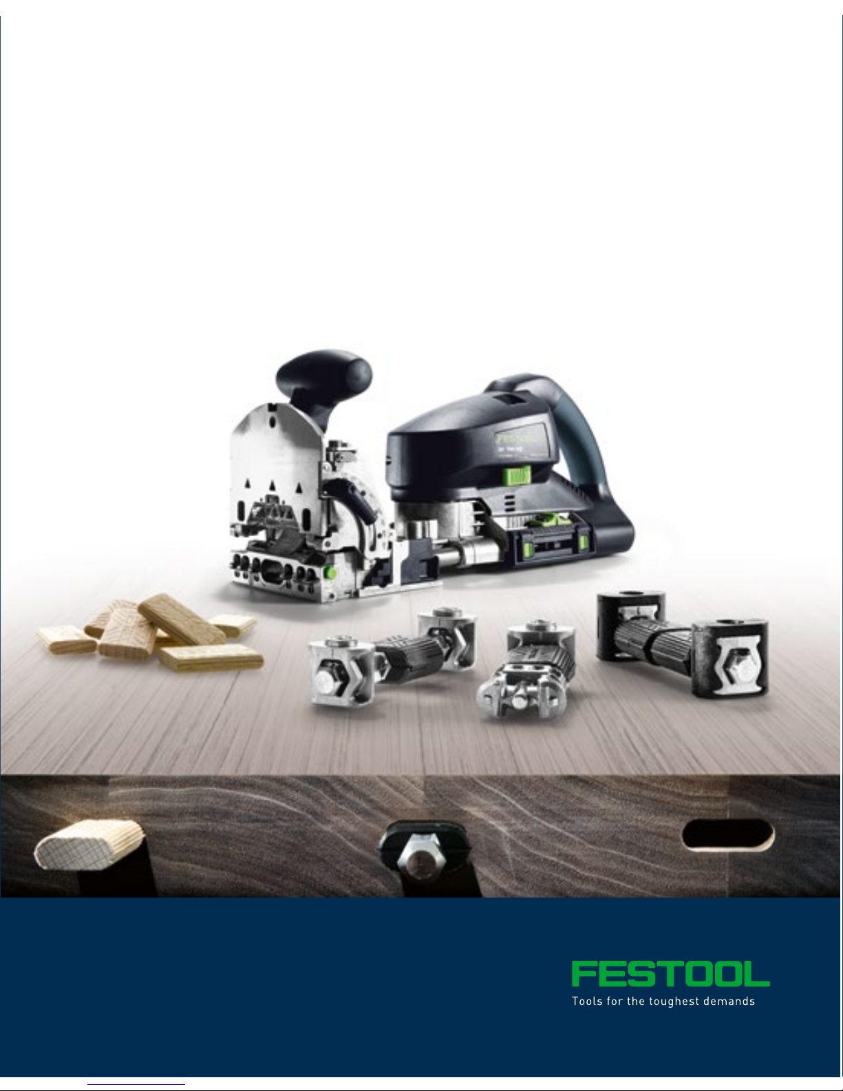
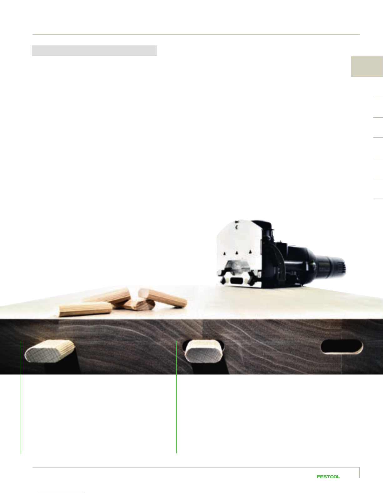
The DOMINO joint. Simply perfect.
Every timber joint has its advantages. The DOMINO connecting system unites them all. In truth,
there are numerous innovations which were developed on the basis of a spontaneous idea.
Such as the DOMINO connecting system. And yet it is also based just as much on the principle
of thinking ahead. Thinking ahead in terms of a timber joint that unifies the benefits of all
previously existing systems: the controversial stability of mortise and tenon, the flexibility of
biscuits used in furniture making and the precision of the round dowel used in frame and rack
making. We found the key for this in the patented pendulum routing movement and the resulting
slots for accepting the specially formed dominos. For a new, complete timber connecting
system, which assures with the highest possible stability. A connecting system that works simply
and with considerably shorter set-up times and which can be used even for tasks that were
previously predominantly the domain of stationary machines. To date we have not only convinced
many tradespeople, but have been able to fill these people with enthusiasm about an idea that
took a significant step further. For timber joints as unique as the DOMINO connecting system itself.
Page 9
76
Page 10
The DOMINO principle: Fast. Easy. Versatile.
Page 11
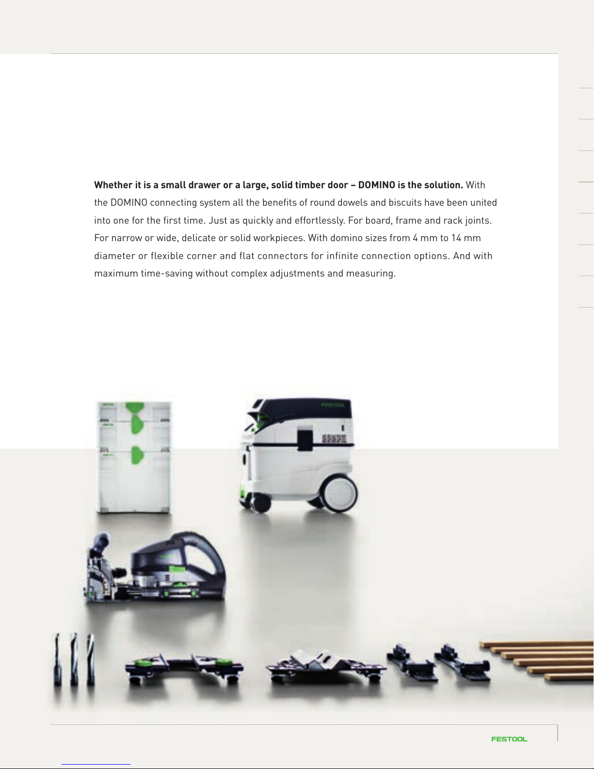
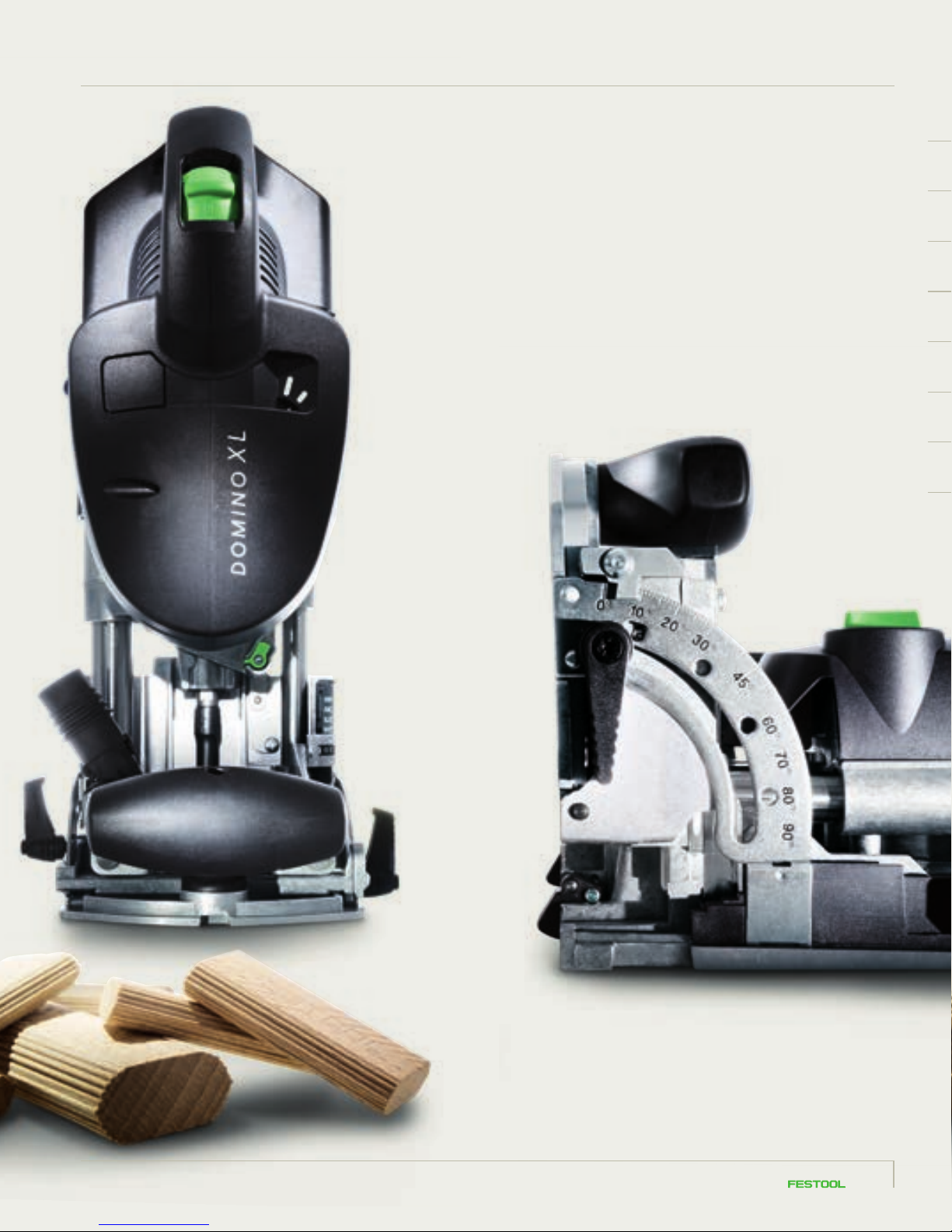
Whether it is a small drawer or a large, solid timber door – DOMINO is the solution. With
the DOMINO connecting system all the benefits of round dowels and biscuits have been united
into one for the first time. Just as quickly and effortlessly. For board, frame and rack joints.
For narrow or wide, delicate or solid workpieces. With domino sizes from 4 mm to 14 mm
diameter or flexible corner and flat connectors for infinite connection options. And with
maximum time-saving without complex adjustments and measuring.
98
Page 12
Page 13
1
DOMINO joining machine fundamentals
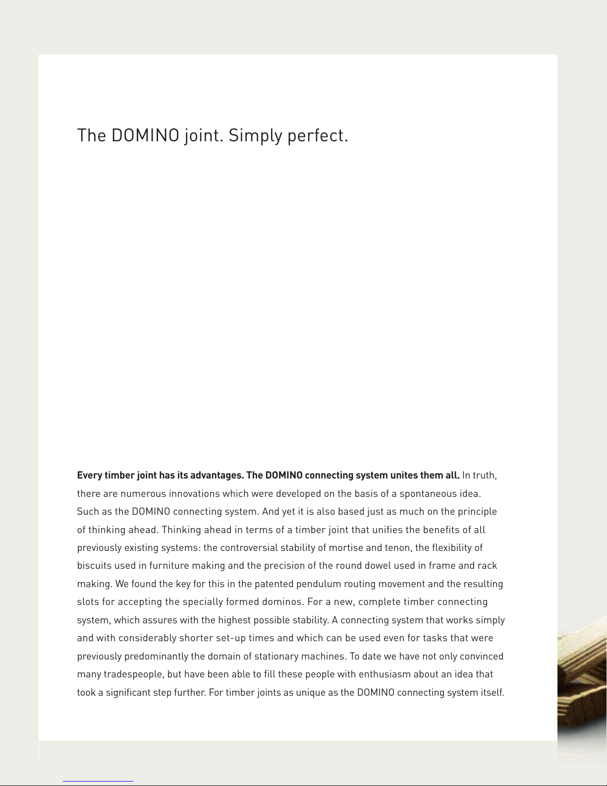
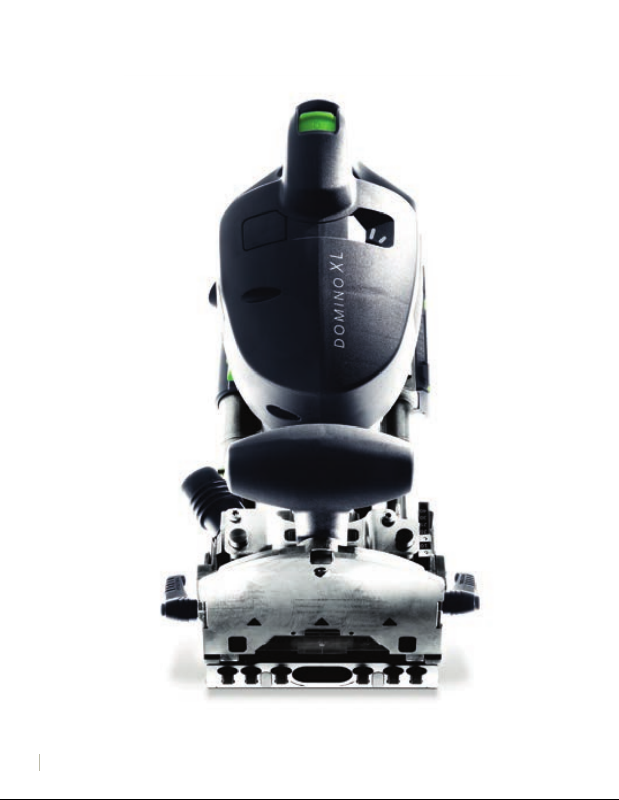
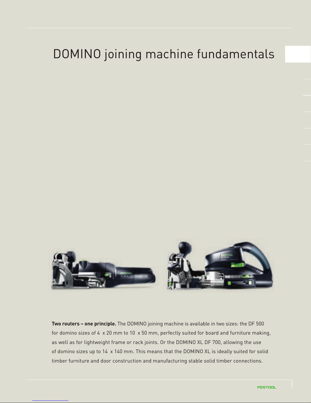
Two routers – one principle. The DOMINO joining machine is available in two sizes: the DF 500
for domino sizes of 4 x 20 mm to 10 x 50 mm, perfectly suited for board and furniture making,
as well as for lightweight frame or rack joints. Or the DOMINO XL DF 700, allowing the use
of domino sizes up to 14 x 140 mm. This means that the DOMINO XL is ideally suited for solid
timber furniture and door construction and manufacturing stable solid timber connections.
1110
Page 14
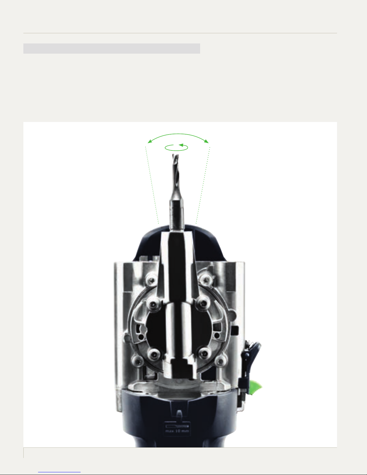
1.1 The DOMINO pendulum router principle
Unique in its manual operation and patent by Festool: the DOMINO joining machine routing movement.
The simultaneous rotating and pendulum movement of the cutter allows smooth working and holes without
scorch marks. Thanks to the pendulum movement the cutters do not overheat, leading to an extremely
high service life.
Page 15
1.2 The domino slot principle
The first domino is positioned via an exact slot, the subsequent dominos inserted in wider
slots with clearance – this allows the joint to be easily aligned. The result is a stable joint,
rotation-resistant from the first domino.
1
Fits exactly.
The slot is precisely routed using
the stop catches (DF 500) or stop
pins (DF 700). The workpiece
is aligned to the edge using this
locating hole and the connection
matches up immediately.
Room to move.
The remaining slots are routed with
clearance. Minor imprecisions in
the remaining domino holes are
compensated for by the DOMINO
connecting system – allowing fast
and efficient progress.
1312
Page 16
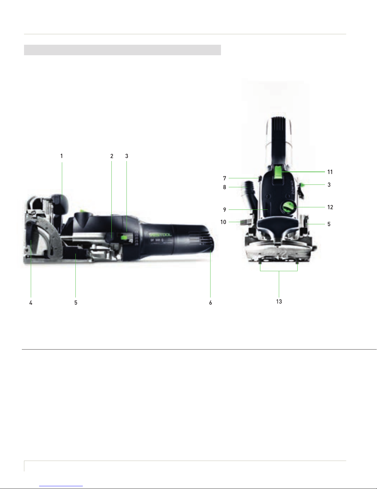
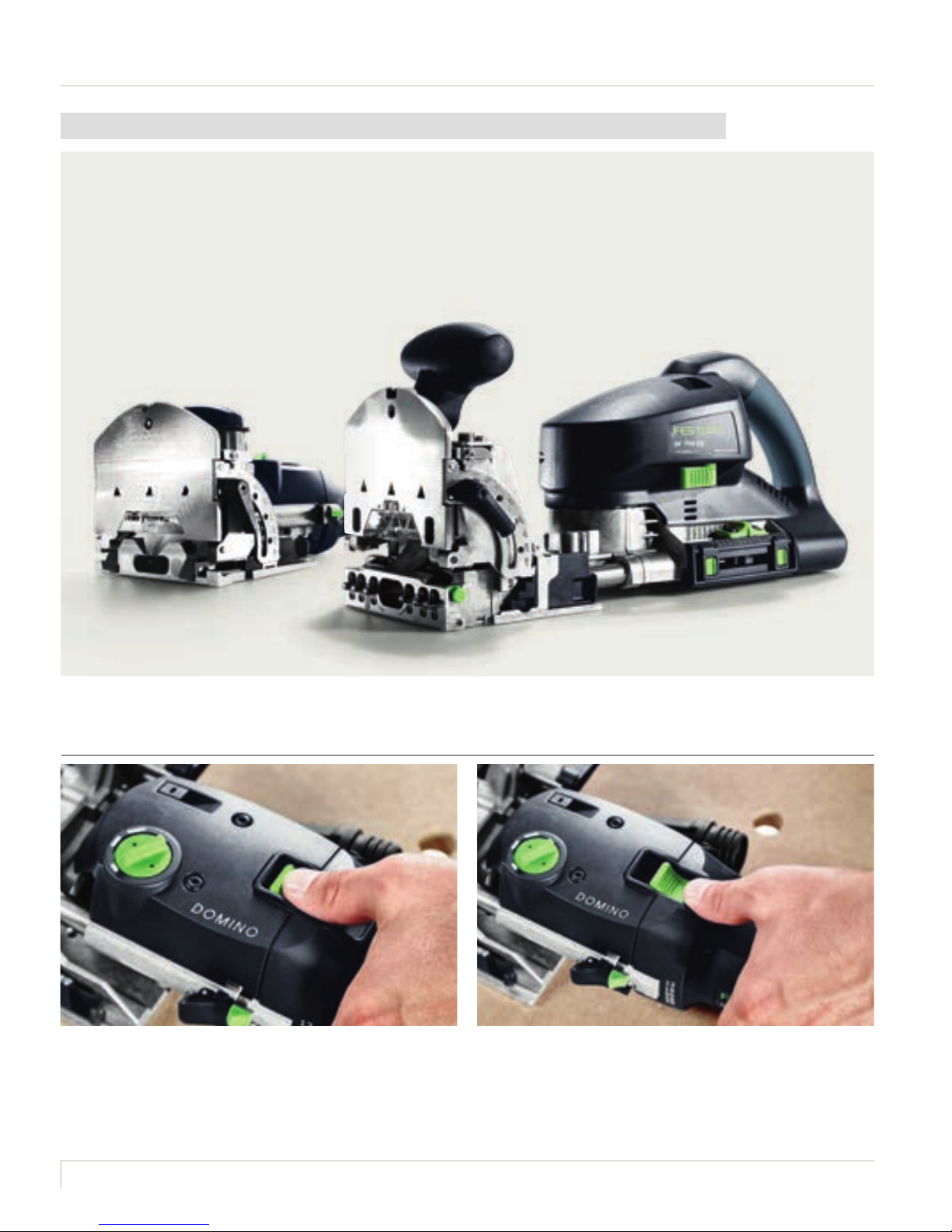
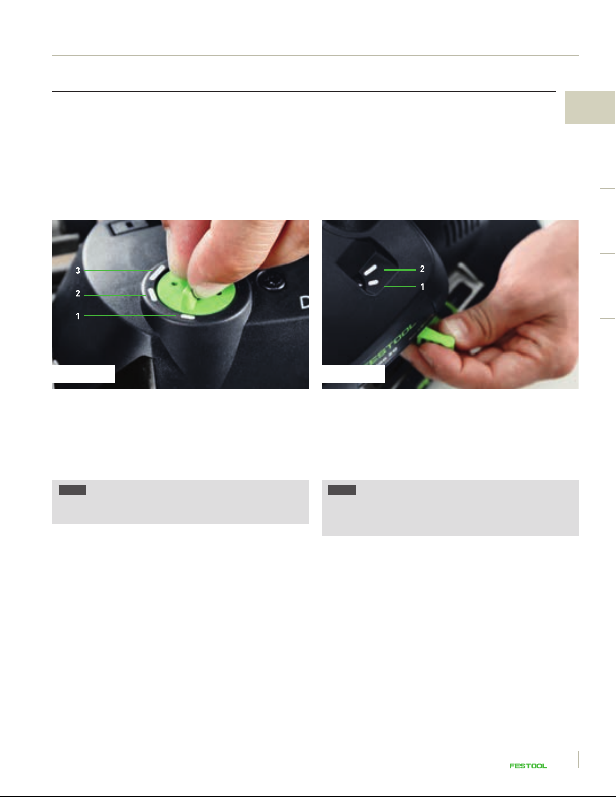
1.3 The DOMINO joining machines: an overview
DOMINO DF 500
1 SECONDARY HANDLE
2 LOCKING LEVER LOCK
3 DOMINO HOLE DEPTH
LOCKING LEVER
4 ANGLE STOP CLAMPING LEVER
5 MATERIAL THICKNESS
PRESELECT SLIDER
6 MAINS CONNECTION
7 SPINDLE LOCK
8 EXTRACTOR STUB
9 MOTOR UNIT/GUIDE FRAME
UNLOCKING
10 ROUTING HEIGHT ADJUSTMENT
CLAMPING LEVER
11 ON/OFF SWITCH
12 DOMINO HOLE WIDTH
ROTARY SWITCH
13 STOP CATCHES
Page 17
1
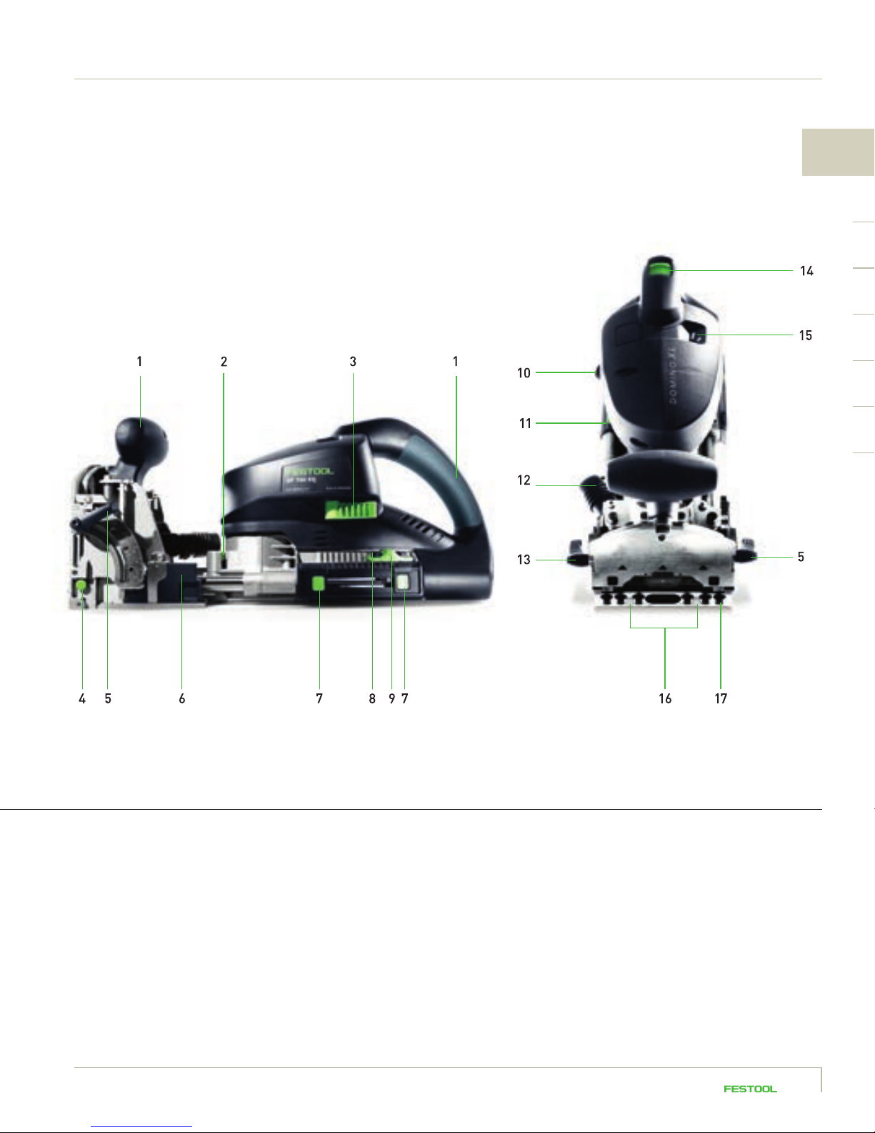
DOMINO XL DF 700
1 HANDLES
2 MOTOR UNIT/GUIDE FRAME
UNLOCKING
3 DOMINO HOLE WIDTH A
DJUSTMENT LEVER
4 STOP PIN UNLOCKING BUTTON
5 ROUTING ANGLE ADJUSTMENT
CLAMPING LEVER
* The terms stop peg and stop pin are used synonymously on the DOMINO XL DF 700.
6 ROUTING HEIGHT ADJUSTMENT
PRESELECT SLIDER
7 ROUTING DEPTH ADJUSTMENT
MARKER
8 ROUTING DEPTH ADJUSTMENT
LOCKING KNOB
9 ROUTING DEPTH ADJUSTMENT
SLIDER
10 MAINS CONNECTION
11 SPINDLE LOCK
12 EXTRACTOR STUB
13 ROUTING HEIGHT ADJUSTMENT
CLAMPING LEVER
14 ON/OFF SWITCH
15 DOMINO HOLE WIDTH INDICATOR
16 RUBBER BUFFER
17 STOP PINS
*
1514
Page 18
1.4 Performing basic settings for the DOMINO joining machines
The DF 500 and DF 700 DOMINO joining machines are generally similar in handling and setting
options. You should be aware of these in order to fully utilise the machines’ flexibility. All basic
settings are explained step by step below. We refer to these basic settings where appropriate in
the individual application examples.
1.4.1 Switching on/off
To switch on the DOMINO joining machine, connect the plug-it
cable to the tool, attach the extractor hose and then push the
on/off switch on the top of the tool forwards and down until it
locks in position.
To switch off, press the on/off switch at the rear to unlock.
Page 19
1.4.2 Selecting hole width
This is where the unique domino slot principle comes in. The first hole, known as the locating hole, is
routed appropriate to the selected domino diameter. Owing to the domino in the locating hole, the joint
aligns exactly with the front edge – the joint is correctly positioned. The remaining holes are routed with
clearance as slots. This makes aligning and joining effortless; the joint is nevertheless exact, perfect
and stable. On the DF 500, three different hole widths can be selected, and two on the DF 700.
DF 500 DF 700
1
DF 500
1 The standard width, corresponding exactly to the domino
width: 13 mm plus the cutter diameter
2 The average hole width, giving the domino some clearance
(6 mm): 19 mm plus the cutter diameter
3 The largest hole width, providing a lot of clearance (10 mm):
23 mm plus the cutter diameter
NOTE Please only change the hole width by turning
the rotary switch with the motor running, but never while
actually routing.
DF 700
1 The standard width for precise routing is:
13.5 mm plus the cutter diameter
2 The hole width with clearance (3 mm) corresponds to:
16.5 mm plus the cutter diameter
NOTE On the DF 700 the corresponding hole width is set
using the adjusting lever on the left of the machine – the
specified hole width can be seen on the display on the top
of the machine.
1.4.3 Selecting domino length and thickness
Because selection of the domino thickness determines the selection of the cutter used, you first decide on
the domino size and then employ the correct cutter (see section 1.4.4).
1716
Page 20
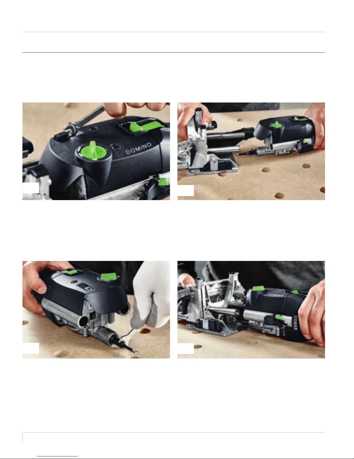
1.4.4 Cutter replacement
After selecting the domino, use the appropriate cutter to make the hole. For example, if you would like
to use an 8 mm diameter domino, you also use the 8 mm cutter.
1
Always disconnect from the mains to change the cutter.
Then raise the unlocking lever using an open ended spanner
(included) until it noticeably locks in place.
3
2
Separate the motor unit and guide frame.
4
Hold the spindle lock on the motor unit, loosen the cutter
using the open ended spanner and screw off. Screw in the
new cutter using the open ended spanner, keeping the spindle
lock pressed. Then release the spindle lock.
Before inserting a new cutter, ensure that the machine, the
guide frame and the guides are clean and free from chippings.
Remove any soiling. Only use sharp, undamaged and clean
cutters. Now push the guide frame onto the motor unit until it
audibly locks in place.
Page 21
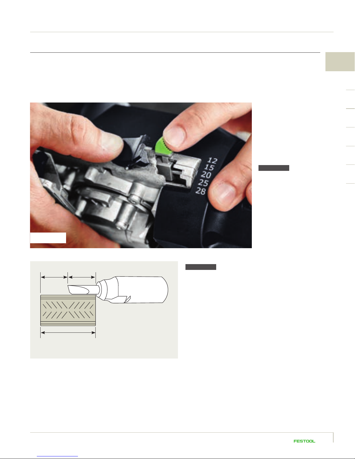
1.4.5 Depth adjustment range
The routing depth determines how deep the cutter cuts into the workpiece. The appropriate routing
depth must be set for the different domino lengths; in most cases half of the domino length. The
routing depth set on the joining machine corresponds to the depth of the domino hole.
DF 500
Open the locking lever lock by
pressing. Now set the required
routing depth using the locking
lever (possible depths ar e 12 mm,
15 mm, 20 mm, 25 mm, 28 mm).
Now release the locking lever
lock again.
ATTENTION
Due to the short shaft length
only the depths 12 mm, 15 mm
and 20 mm are allowed when
using the 5 mm diameter cutter.
1
DF 500
10 mm 10 mm
Domino 4 x 20 mm
20 mm
Festool
D 4-NL 11 HW-DF 500
ATTENTION The D 4-NL 11 HW-DF 500 specialist cutter is
available for the 4 x 20 mm dominos. Please use a routing
depth of 20 mm when working with this domino and cutter.
However, the true routing depth is 10 mm, because the
specialist cutter has been shortened by 10 mm due to the risk
of fracture. This domino can only be positioned centrally.
1918
Page 22
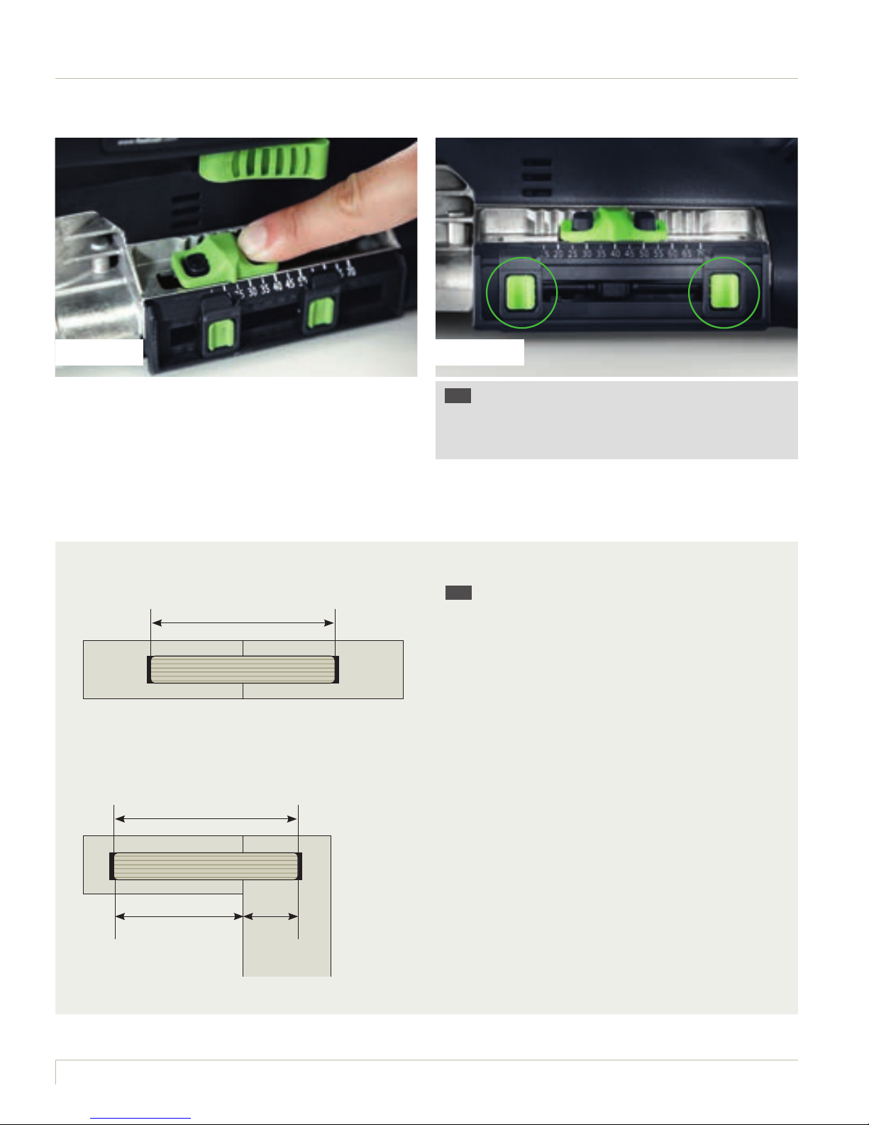
DF 700 DF 700
DF 700 Press one or both locking switch to set the routing
depth. Move the routing depth setting slider to the required
routing depth. On the DF 700, the possible routing depth is
between 15 mm and 70 mm. Now release the locking switch–
briefly check that the slider has locked in to position.
Domino centred
40 mm
Randomly located domino
40 mm
TIP You can mark two routing depths using the two green
markers and easily move between the two using the slider.
For example, this can be helpful when using a domino depth
for spacing as well as for repeated, identical routing depths.
TIP The domino should generally be centred
within the joint; that is, the routing depth should
correspond to half of the domino length. However,
depending on the workpiece or joint type, it may
be necessary to locate the domino randomly. In
this case, both of the holes routed in the workpieces
must together correspond to the length of the
domino being used.
Example: The domino being used is 40 mm long;
the left hole is 28 mm deep, the right hole 12 mm
– that is, together 40 mm.
28 mm 12 mm
Page 23
1.4.6 Height adjustment range
The routing height setting on both the DOMINO DF 500 and the DF 700 is performed using the preselect
slider, allowing predefined heights to be used. Alternatively, any individual dimension can be set using
the scale. The routing height defines the distance from the workpiece top from which the hole is routed
into the workpiece. Selection of the correct routing height depends on the material being worked on,
and also on the type of joint to be produced on the other. Here, it is not absolutely necessary for the
routed hole to be in the centre of the material. You can therefore find more information on the topic of
routing height in the description of the individual applications in section 4.
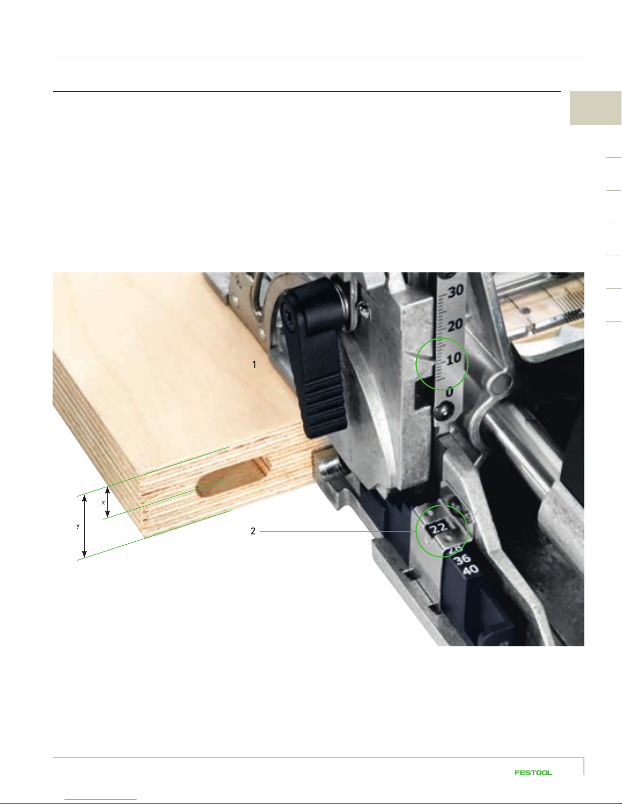
1
y = Material thickness
x = Distance from top of workpiece to centre of routed hole
1 Scale for indiv idual settings (distance from top of
workpiece to centre of routed hole)
2 Pres elect slider (material thickness)
DF 500 – set routing height using the preselect slider.
The dimensions set using the preselect slider determine the material thickness being worked and centre the routed hole exactly
in the middle of the selected disc size – without you having to calculate the distance to the centre. Release the routing height
adjustment clamping lever and lift the front section of the guide frame using the secondary handle. Now select the required disc
size using the slider (16 mm, 20 mm, 22 mm, 25 mm, 28 mm, 36 mm, 40 mm). Then push the front section of the guide frame
downwards until it stops and close the clamping lever.
2120
Page 24
DF 500
DF 500 – set any routing height
The given dimension defines the distance between the
underside of the leaf and the centre of the routed hole. Loosen
the routing height adjustment clamping lever and, using the
secondary handle, raise the front section of the guide frame.
Then push the slider towards the motor unit until it stops.
Set the required routing height on the scale by moving the
front section of the guide frame horizontally. Now close the
clamping lever.
DF 700 DF 700
DF 700 The routing height is adjusted on the DF 700 equivalent
to the DF 500. The only difference to note: here, the preselect
setting does not determine the board thickness, but instead
the true distance from the top of the workpiece to the centre
of the routed hole.
22
NOTE The alignment of the clamping levers can be
adjusted by lifting them. In the tightened state, they
should not overhang past the contact surface.
Page 25
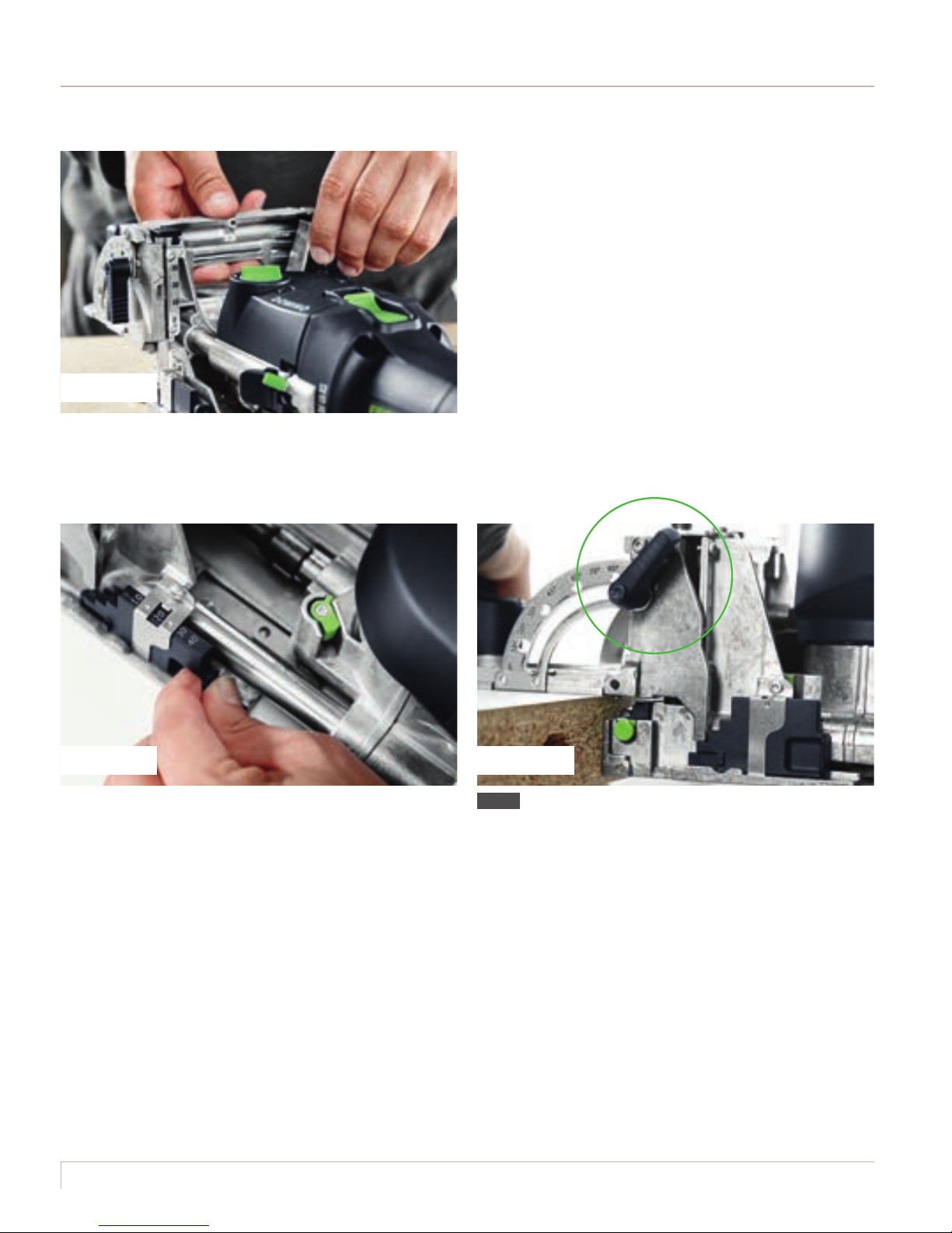
1.4.7 Angle adjustment range
Number of equal sides Cutting angle DOMINO angle
3 Triangle 60 30
4 Square 45 45
5 Pentagon 36 54
6 Hexagon 30 60
7 Heptagon 25.7 64.3
8 Octagon 22.5 67.5
For mitred joints, the joining machine routing angle can be set using stages, predefined angles or any
other degree between 0° and 90°. The precisely machined dominos optimally align the workpiece and
prevent the mitre from slipping when being glued.
DF 500 and DF 700: Loosen the angle stop clamping lever to
adjust the routing angle. Then set the required angle, either
continuously on the scale between 0° and 90° or in stages at
0°, 22.5°, 45°, 67.5°, 90°. Close the clamping lever.
TIP Route thin workpiece with a mitre. Set the required
angle. Loosen routing height adjustment clamping lever, push
the slider towards the motor unit until it stops and then push
the angle stop all the way down. Close the clamping lever.
1
ATTENTION When using mitre routing, set the routing
height and depth as low as possible, otherwise there is a
danger that the cutter will penetrate through the opposite
side of the workpiece.
TIP Material thicknesses from 15 mm can be mitred
using the 4 x 20 mm domino.
The table shows some of the most commonly used mitre angles:
2322
Page 26
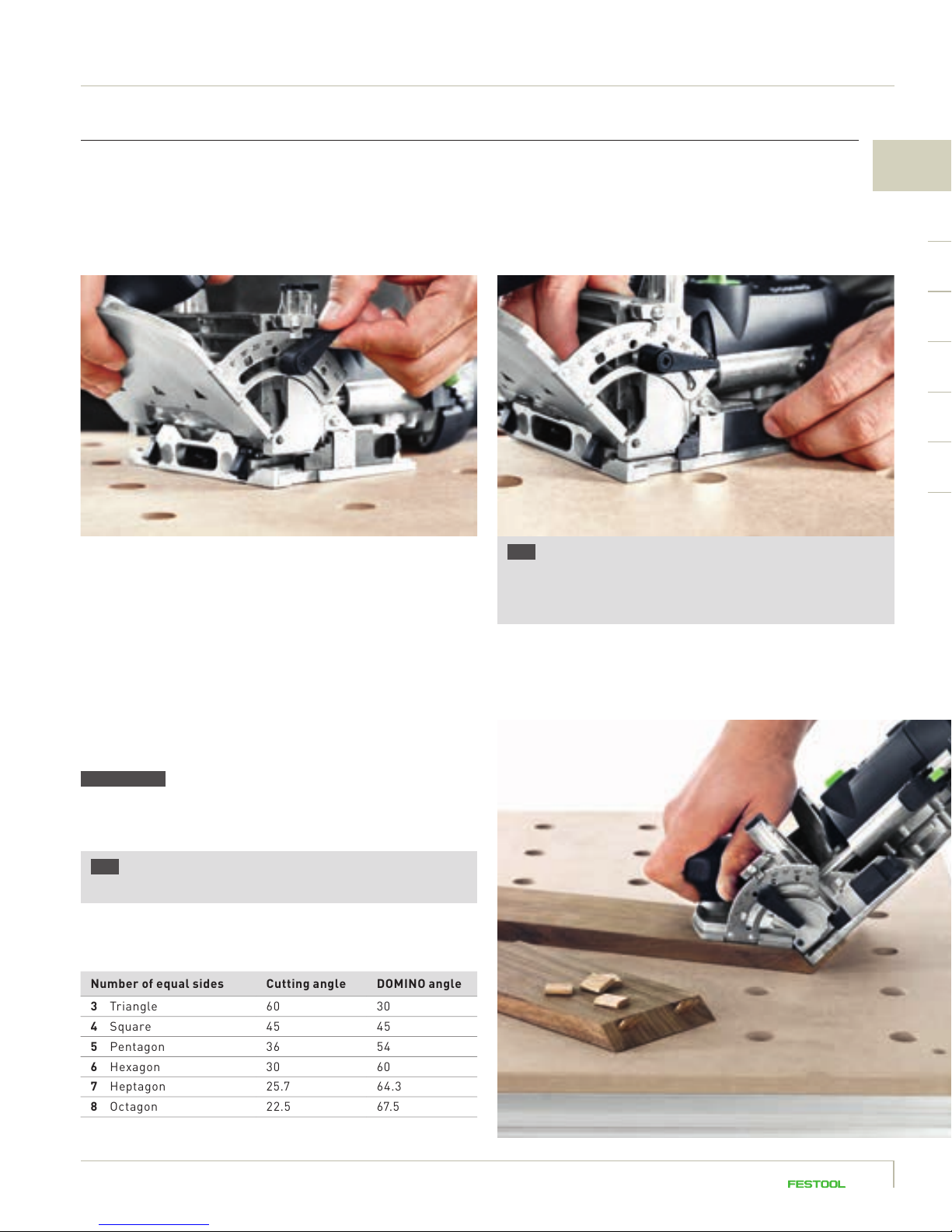
1.4.8 Working with the stop system
One of the greatest time advantages of working
with DOMINO joining machines is the result of
working without the need for complex measuring
or marking – the machine can be positioned
quickly and accurately by using stop catches
(DF 500) or stop pins (DF 700).
The edge of the workpiece is visible in the machine’s upper
triangular viewing window. If you do not need the stop
catches, they are automatically pushed aside during the
routing process.
It is easiest to quickly define the positions of repetitive domino
holes by using the integral stop catches for both parts of
the workpiece. The distance between the stop catch and the
router centre is 37 mm. Place the DF 500 at the edge of the
workpiece using a stop catch.
TIP With the aid of the additional stop provided with the
DF 500, the lateral distance to the DOMINO centre can be
reduced from 37 mm to 20 mm.
DF 500 It is possible to define the positions of the DOMINO
routed holes by simply drawing and locating the machine
on the scribe mark looking through the viewing window.
Page 27
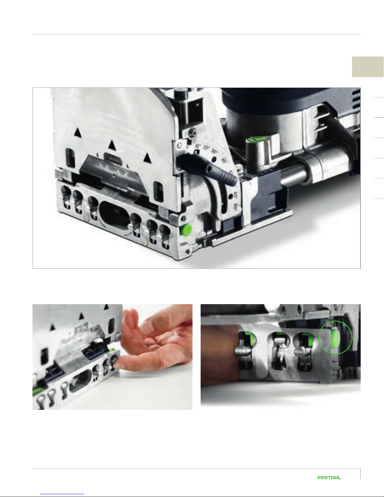
1
The DF 700 possesses an innovative stop system, allowing even domino groups to be quickly and precisely positioned in relation
to a reference edge using the integral stop pins.
There are six stop pins on the stop side of the joining machine. Unnecessary stop pins can be pushed aside individually and lock
in place, and can all be released again by pressing the button on the side of the machine (see markings in the figure).
2524
Page 28
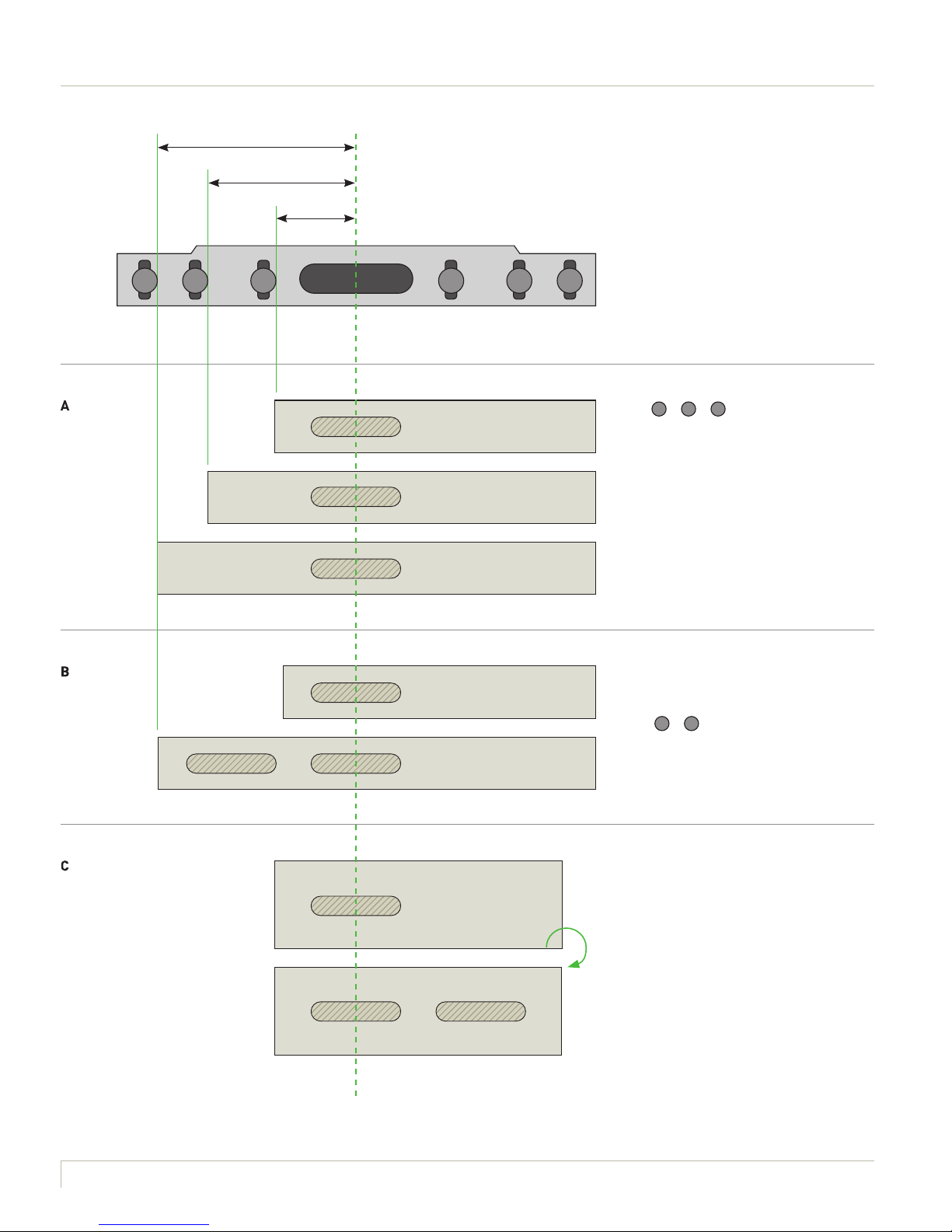
50 mm
37 mm
20 mm
1 2 3 3 2 1
The stop pins serve as distance pieces
to the router centre and can be separately located.
A
Pins (
1
– 2 –
3
) allow three
separate distances to a reference
edge.
B
The pins allow two domino holes to
be placed adjacent to each other
at a defined distance to a reference
1
edge (
–
3
).
C
The pins allow two domino holes to be
placed by rotating the workpiece, e.g.
for the same moulding cross-section.
Page 29
Additionally, it is possible to insert the pin in the previously routed domino hole and to use the edge of the domino
hole as a stop. This means you can define domino holes over larger, uniform distances independent of the edge of the
workpiece and without marking. (In the example using pin 2 in the drawing.)
37 mm 37 mm 37 mm 37 mm
1
2726
Page 30
1.4.9 Working with extraction
Large amounts of timber chippings are created when working with the DOMINO joining machines. To improve
chip transfer out of the routed hole during the routing process, and to also protect your own health, we
recommend you always work with dust extraction. However, please examine all domino holes for chips after
routing and empty them if necessary.
Selecting the correct mobile dust extractor:
it all depends on the dust category!
In addition to improving the progress of your
work, the mobile dust extractor also primarily
ensures improved health when working with
the DOMINO joining machines: because when
working in dusty environments, in particular with
materials such as timber, the dust produced
can become a serious health risk. This has been
shown by a recent meta-analysis*, which established that the relative risk of asthma amongst
employees exposed to timber dust is 1.53 times
higher than that of the normal population.
So do yourself a favour and make sure you have
clean air in your workplace – and work with
a tested and approved mobile dust extractor.
You will also be complying with all the statutory
regulations, too.
* Source: Perez-Rios M, Ruano-Ravina A, Etminan M, Takkouche B. A.
Meta-analysis on wood dust exposure and risk of asthma. Allergy
2010;65:467-73.
Page 31

The Festool mobile dust extractors were especially developed for and coordinated with our tools, and
are therefore also ideal in conjunction with the DOMINO joining machines. Whether you choose a mobile
dust extractor with a volume of 26, 32 or 48 litres and with or without automatic AUTOCLEAN cleaning
technology, depends entirely on your personal preferences and other use preferences.
It is important that you work with a mobile dust extractor in dust category M.
This dust category is approved for all timber dusts which are created when
routing with the DOMINO joining machines, but also for dusts produced by putty,
fillers and cement, concrete, tile adhesives and paints such as latex and oil
paints, and also materials containing sand and gravel.
1
2928
Page 32

Page 33

2
The domino
3130
Page 34

2. The domino. The shape makes the difference.
Not flat. Not round. Just domino.
The difference is in the detail. More precisely: in
the shape. Dominos unify all of the benefits of
round dowels and biscuits. And are therefore as
stable as mortise and tenon. They are available
in 14 fixed sizes or as rods – for both inside and
outside, and for delicate and solid workpieces.
Round dowels
The traditional solution for frames and racks.
Round dowels are one of the most important connecting
elements in furniture making, allowing timber connections
to be quickly and reliably aligned. Because round dowels
do not allow offsets, exact drilling is generally performed
on stationary or semi-stationary machines.
Biscuits
The standard for boards for decades.
Biscuits are quick and always used with manually
operated machines, pencil marks are used to position
them. Because the biscuits are shorter than routed
slots, a slight offset during routing is not a problem.
The joint is movable, however this advantage is off set
by the additional position during gluing up.
Page 35

Dominos
Not flat. Not round. Just domino.
The special shape, in combination with swelling glue pockets and longitudinal grooves, gives the dominos
a secure hold. For absolutely rotation-resistant connections and maximum stability. And with substantially
faster working: the first domino hole is very easily positioned and precisely routed with the aid of stop catches
(DF 500) or stop pins (DF 700). It immediately aligns the workpieces, being connected exactly and flush to
a reference edge. However, the DOMINO system even tolerates minor imprecisions in the additional domino
holes, routed with clearance. Compared to traditional connecting elements, you always have the choice of
working precisely or with clearance when working with DOMINO joining machines.
2
NEW The domino corner and flat connectors
As stable as dominos, but can be flexibly released again if necessary.
3332
Page 36

Dominos.
100 % rotation resistant
From the ver y first domino,
the joints are absolutely
rotation resistant without
additional workpiece
alignment.
Highest stability
The unique shape of the
domino in combination with
swelling glue pockets and
longitudinal grooves, gives
the dominos a secure hold.
Fits perfectly
The DOMINO joining machines
route the holes to an exact fit
where needed. The domino’s
special groove geometry
ensures a perfect precision fit.
For inside and out
Dominos are available in two
materials: Beech for interior
applications and weatherproof,
insect- and mould-resistant
Sipo dominos for outside
applications.
Beech dominos are certified by
the Pan European Forest Council
(PEFC) for timber products from
sustainable, caring and responsible
forest management.
Sipo dominos are weatherproof,
and insect- and mould-resistant,
and are therefore ideally suited
for outside applications. They are
manufactured from timber originating in sustainably managed and
controlled forests.
Always a stable connection.
The DOMINO system provides the correct dominos for
every application. With its range of sizes, two timber
types for inside and outside applications and additional,
individually adaptable rods, there are practically no
limits to this system’s options.
The 8 –14 mm diameters are also available as rods and in t wo t ypes of timber for interior and exterior applications.
* Flat connectors – here with the optional enlarging clips around the transverse anchor.
Page 37

Environmentally friendly
All dominos originate from
sustainable forest management.
The Beech dominos are certified
by the Pan European Forest
Council (PEFC).
And now also flexible
Connect even faster. And release
again if needed. The new corner
and flat connectors for the
DOMINO XL DF 700 guarantee
a stable domino connection –
but also add the option of quick
release if required.
2
NEW
Corner
connectors
Flat
connectors*
3534
Page 38

Page 39

3
DOMINO system accessories
3736
Page 40

3. DOMINO system accessories. For even greater application versatility.
The Festool system stands for application versatility and simplifies your work with accessories
thought through to the finest detail: with a variety of stops, compatible with both DOMINO joining
machines, even the most complicated of shapes
can be easily connected.
Handrail fence
Timber rods in diameters from 35 – 60 mm are rotation
resistantly fixed by a single domino: simply push on the
handrail fence, precisely adjust, fit the workpiece and
route.
(For DOMINO DF 500 and DOMINO XL DF 700)
DETAILS on working with the handrail fence can be found
in the example applications on page 56.
Page 41

Trim stop Cross stop
3
Trims of 22 – 70 mm width can be quickly positioned and
fixed centrally using the trim stop – ideal for rack joints.
(For DOMINO DF 500 and DOMINO XL DF 700)
Repetitive hole centres of 100 – 205 mm can be easily
transferred using the cross stop – without scribing the
workpiece.
(For DOMINO DF 500 and DOMINO XL DF 700)
DETAILS on working with the trim stop can be found
in the example applications on page 50.
DETAILS on working with the cross stop can be found
in the example applications on pages 74 and 79.
3938
Page 42

DF 700 support surface extensionDF 500 additional stop
DF 500 DF 700
The additional stop provided with the DF 500 increases
the contact area and reduces the lateral distance of
the stop catches to the DOMINO centre from 37 mm
to 20 mm. This allows precise positioning of narrow
workpieces.
The support surface extension provided with the DF 700
allows the contact area to be extended for routing on
the edge of the workpiece and the machine is thus more
reliably guided.
40
DETAILS on working with the additional stop and the
support surface extension can be found in the example
applications on page 76.
Page 43

4
Practical application examples
41
Page 44

4.1 Overview: connections with DOMINO joining machines
The DOMINO system is ideally suited for board,
frame and rack joints, involving narrow or wide,
delicate or solid workpieces with dominos ranging
from 4 to 14 mm in diameter or flexible, separable
corner and flat connectors. In short, the DOMINO
system is perfect for realising infinite connection
possibilities.
The following chapter showcases examples of
how to work with these various connection types.
Naturally all of these examples are variable in
terms of size, material, and the size and number
of dominos, etc. Nevertheless, these examples
always demonstrate the basic procedure which
can be used as a reference.
Applications
Board connections
Drawers from 4 mm dominos
Furniture making with 5 mm and 6 mm dominos
Solid timber furniture with 8 mm and 10 mm dominos
Solid timber furniture (e.g. beds) with 12 mm and 14 mm dominos
Rack connections
Lightweight rack cons truction (e.g. chairs) up to 10 mm dominos
Stable rack constr uction (e.g. tables) with 10 mm to 14 mm dominos
Frame and stand designs
Frame joints
Furniture fronts in frame design w ith 8 mm and 10 mm dominos
Solid timber furniture in frame de sign
Entrance door s and internal doors
Additional applications
Connection of narrow tr ims from a w idth of 25 mm
Connection of rods w ith handrail fence
Connection of wide rails (e.g. solid timber panels)
Corner connectors from 30 mm material thickness, separable
Flat connectors from 3 0 mm material thickness, separable
Page 45

DOMINO joining machines DF 500 DF 700
4
very suitable suitable
4342
Page 46

4.2 Frame joints
The applications of the DOMINO connecting system are virtually unlimited, as well as uncomplicated.
Just one domino is enough to connect a frame corner securely and ensure it will not twist – so attractive
furniture fronts can be quickly and easily achieved.
With the DF 500, very small dominos can be used even for furniture joints, making it possible to
process very small spindles or narrow frame rails.
With the DF 700 in contrast, stable frame joints can be created in the same way, for example, for
beds, tables or internal doors. Thanks to the larger routing depth, the DF 700 is also suitable for
pinned joints. Some of these connection options are demonstrated in the following examples.
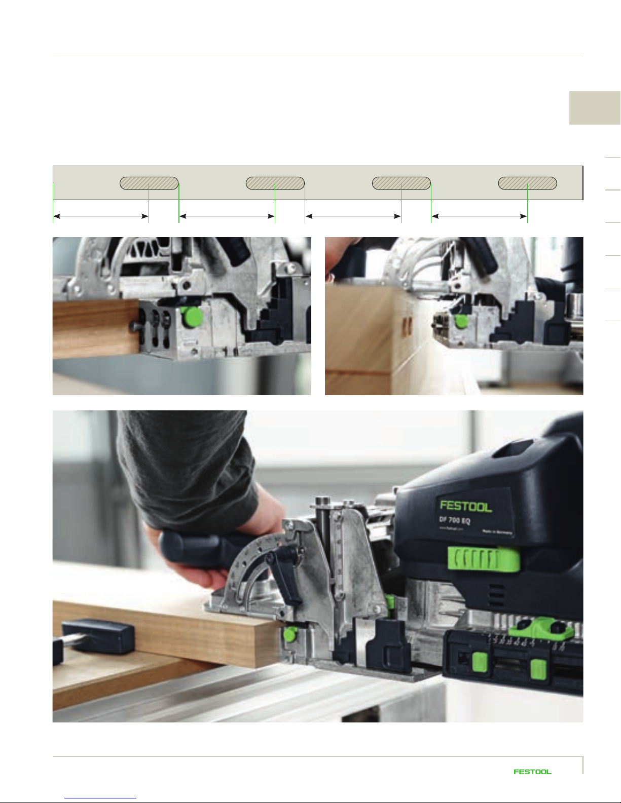
4.2.1 Mitred frame joint
1
In this example, we are processing 5 x 30 mm dominos.
Set the routing depth to 15 mm for this.
Page 47

2 3
4
Select the routing height based on the workpiece; in this
example, the frame is 20 mm thick. Set the routing height
on the DF 500 to 20 mm in this case. The width of the frame
in this example is 60 mm.
We are using two dominos per corner connector for maximum
stability. Place the routing machine on the mitre cross section
and carefully work with the stop catch at the side against the
tip of the mitre. Route the first hole with precision.
4
For the second routed hole, either mark out the position or
run the machine flush along the outside tip of the mitre. This
routed hole can either be precisely routed like the first hole –
which increases the stability of the joint but requires more
precision – or it can be routed with clearance – but then you
must use a sufficient amount of glue for the joint.
Use this method to route the holes in all four frame rails.
5
Insert the dominos, using a sufficient amount of glue, join the
frame rails and brace them with clamps.
4544
Page 48

4.2.2 Butted frame joint
When connecting frame rails without
mitring, i.e. butted joints, proceed
as you normally would. This example
shows another option for using
the DOMINO joining machine on the
workpiece.
1 2
Set the routing height to match the thickness of your
workpiece. For the routing depth, select half the domino
length. Route the holes by either using the right hole width
for both for extreme precision fit or routing the second
hole with clearance, if desired.
The routed holes can be set by marking them out as usual or
using the stop system with the scale in the viewing window –
in this example, 15 mm from the outside edge. For this option,
place the scale with the 15 mm marking at the edge of the
workpiece.
Page 49

3 4
4
The second routed hole is set here using the stop catch.
This method makes it possible to position two dominos next
to each other working from just one reference edge.
TIP When using the stop catches, the edge of the work-
piece can be seen in the triangular viewing window of the
DOMINO joining machine.
Use this method to carry out routing for all four frame rails,
whereby every second frame rail is routed into the workpiece
lengthwise instead of into the front.
51 2
Then glue the frame rail and brace with pads and clamps,
if necessary.
TIP If the frame rail needs to be rebated or grooved, the
rebating depth must be added in advance when routing
the domino holes, so that the domino is centred later despite
the rebate (which then takes up part of the depth of the
domino hole).
4746
Page 50

4.2.3 Stable frame joints with the DF 700
Use the DOMINO DF 700 for stable frame joints such as for doors,
where larger dominos can be processed for even greater stability.
In this example, a panel door is created with a pinned internal rebate
and additional tenon.
The DOMINO joining machines are unique in that you can set the routed
holes even after rebating, which would not be possible with a classic drill
for conventional domino joints, for example, due to the lack of support
surface. This ‘pinned joint’ requires small deviations in the routing
depth setting, which are explained in the following.
TIP Due to the pinned joint, the 14 x 140 mm domino cannot be
processed despite the maximum routing depth of 70 mm for the
DF 700. The maximum possible standard domino is the 14 x 100 mm.
However, if you wish to make full use of the maximum routing depth
and cut the domino itself to the correct maximum size, you can do
so by cutting the domino to the appropriate length and creating the
perfect domino size yourself.
Page 51

1 2
4
Mark out the desired position of the domino and work using
the viewing window. Route into both parts of the workpiece
at the maximum routing depth (70 mm each) with the 14 mm
router.
In the end grain, set both routed holes with the correct hole
width – in this case the dominos are later glued and then fit in
precisely. The routing height is half of the workpiece thickness
(which is 40 mm in this example, so the routing height setting
is 20 mm).
In the lengthwise rail, set the routed holes with a 70 mm
routing depth as well, but route the first hole with precision
and the second as a slot with clearance. Proceed likewise
for the additional lengthwise and crosswise rails.
3 4
Then cut the dominos to fit the ready-made
holes. In this example, the nominal domino
length is 115 mm, which is calculated by
doubling the routing depth of 70 mm = 140 mm
and subtracting the pinned joint of 25 mm =
115 mm. Cut the domino a few millimetres
shorter (so that later the glue has enough
space), down to 112 mm. Chamfer the cut
domino at the edges using a sanding block.
Then drive the dominos all the way into the routed holes
in the end grain, adding glue to the joint.
Join the lengthwise and crosswise rails using fastening
clamps and glue the joint.
4948
Page 52

4.3 Rack joints and secure spindle positioning
Making rack joints with the DOMINO joining machine saves an incredible amount of time. Especially
when relatively narrow spindles are being processed, working with the trim stop (available as an
accessory or included in the DF 500 set) is recommended for safe and precise workpiece routing. This
trim stop fits both the DF 500 and the DF 700 and securely holds spindles with 22 – 70 mm thickness.
Page 53

1 2
4
Mount the trim stop onto the DOMINO joining machine
according to the operating instructions.
Set the width of the trim stop to the thickness of your spindle
by adjusting the guide in the parallel side fence to the correct
dimension using the scale and the green rotary wheels. In
this example, we are working with 30 x 30 mm rectangular
spindles.
3 4
Using the spindle as a guide, ensure that the trim stop dimension
fits perfectly; make further adjustments if necessary.
To process a 6 x 40 mm domino as in this example, use the
6 mm router (6 mm dominos can only be processed with
the DF 500). For details on changing the router, see chapter
1.4.4, page 18.
5150
Page 54

Set the routing height to 15 mm, so that the domino is centred
on the spindle later. Set the routing depth to 20 mm, so that
the 40 mm domino is later positioned evenly between the
spindle and the handrail. Route the hole in the spindles using
the narrow hole setting.
NOTE You can naturally use the DF 700 to apply this
method with a domino diameter of 8 mm or greater.
CAUTION Especially with handrails, it is often not possible
to position the joining machine securely on the side of the
workpiece due to the handrail design; the round shape
prevents the DOMINO joining machine from having a secure
support surface.
6
The trim stop provides additional support in these cases:
mark out the desired position of the spindles on the handrail,
where routing will take place later. From this marking, set
an additional marking 10 mm away (or 15 mm when using the
DF 700) – this is where the joining machine will be placed
later. Then set the routing angle to 90° so that you can route
vertically into the handrail from the top. The routing depth is
20 mm again, as with the spindles, with the 6 x 40 mm router
to be processed.
Page 55

75 8
4
Then set the trim stop to the width of the handrail.
Route the holes in the handrail, positioning the joining
machine on the second marking.
96
Applying a sufficient amount of glue, insert the dominos into
the routed holes and join the handrail to the spindles.
5352
Page 56

TIP Of course, bevelled joints are also possible with
spindles needed especially for going up and down stairs.
In this case, set the cutting angle of the spindle on the
DOMINO joining machine during routing (using the routing
angle adjustment) and route the domino hole.
Set the routed holes in the handrail as described above.
Then join the spindle and handrail together.
TIP For workpieces where a secure support surface is
possible for the joining machine, simply marking out the
domino holes or central axis of the spindles is sufficient
(in this case you do not have to work with the trim stop).
Set the routing height to the centre of the workpiece. Mark
out the axis distance of the spindles on the top side of the
workpiece. In this case (when simply using markings) bring
the scale in the viewing window of the DOMINO over the
scribe mark and set the routed holes. A second scribe mark,
as in the example of the handrail above, is not necessary here.
Page 57

Notes
4
5554
Page 58

4.4 Round profile joints
When connecting round timber profiles, such as those used for handrails, the handrail fence is
available as an accessory to ensure a secure workpiece hold. This part fits both the DF 500 and
the DF 700 for diameters from 35–60 mm. The following example describes how a stop is created
using this handrail.
Before starting, ensure that the correct router is used. In this
example, we are processing an 8 x 40 mm domino, so the 8 mm
router must be used.
Set the routing depth to 20 mm.
Select the routing height so that the domino is offset towards
the inside of the mitre, preventing the routing from going
1
through the workpiece. In our example with a round timber
profile with 40 mm diameter, set the routing height to 20 mm.
Page 59

4
2
Mount the handrail fence onto the DOMINO DF 500 or DF 700
according to the operating instructions.
TIP Before processing your workpiece, it is important
to create a sample piece and make fine adjustments to the
handrail fence according to the operating instructions.
3
The handrail fence holds the workpiece securely and centres
it automatically thanks to the prism-shaped contact surfaces.
4 5
Set the routing angle on the joining machine according to your
sawing angle on the workpiece. In our example, the handrail
was sawed at 15°, which means the routing angle is set to
75°; this is equal to 90° minus 15°. Secure the workpiece, on
the MFT multifunction table. Then route the hole in both
parts of the workpiece.
Insert the 8 x 40 mm domino into the routed hole, applying
glue to the joint. Then join the two workpiece parts together –
the joint is secured from twisting with just one domino!
5756
Page 60

4.5 Stable, separable corner connectors
The separable corner connectors provide
even more flexibility, especially with large,
solid workpieces like tables or beds. These
connectors allow for quick and easy assembly and disassembly of furniture pieces,
making transport a breeze. In terms of how
they are processed, the connectors are very
similar to the securely glued dominos to
a great extent and can be easily mounted
thanks to the large pulling and tightening
distance.
The example provided here demonstrates
how to create a table or bedpost.
Page 61

For corner connectors, you need the following components from the
DOMINO corner and flat connector system:
Dimensions for routing the
DOMINO corner connector
40
1. Anchor bolt
2. Self-drawing expansion bolt – for
a secure hold in the workpiece.
3. Transverse anchor including stud
4. DOMINO connector covers – clipped
around double-headed or anchor
bolts. Items included with
double-headed or anchor bolts.
x + min. 10
min. 2 5
y
min. 2 5
Only suitable for joining timber or timber-like material s in furniture construction (no lightweight
building materials!) The DOMINO connec tor is only a connecting element, not a load-bearing
element. Observe minimum routing depths and edge distances! For indoor use only!
C
x
B A
50 25
Hole width Routing depth Routing height
A
B
C
25 mm ~y/2
50 mm ~y/2
x + min. 10 mm;
min. 25 mm in
total
40 mm
4
Per corner connector:
1 x anchor bolt including DOMINO connector cover
1 x transverse anchor including stud
1 x expansion bolt
Optional: 1 x cover cap in silver, light brown or dark brown
The corner and flat connectors are always processed with
the 14 mm router on the DF 700.
5958
Page 62

1 2
Set the routing depth of the joining machine to 25 mm –
set the markers to 25 mm and 50 mm.
It is a good idea to work with the stop pins in this case. Select
the pins depending on the desired hole distance. Ensure that
the routing for the corner connector has a minimum distance
of 37 mm from the edge of the workpiece. If you work with the
stop pins, use the centre pin at least.
3
Route the domino holes in the table or bedpost (narrow hole
width) with a routing depth of 25 mm. Set one hole for the
expansion bolt of the corner connector, the others for the load
transfer via traditional dominos.
Page 63

4 5
4
Change the routing depth to 50 mm and route the holes
(narrow hole width) in the frame according to the scribe mark
or using the stop pin system. The routing height is determined
by the material thickness, using the usual method you already
know from working with your DOMINO DF 700. In this example,
the frame has a material thickness of 30 mm. Set the routing
height to 15 mm so that the routed hole is centred in the
material.
Then set the routing depth to 25 mm for routing the transverse
hole. (This dimension depends on the workpiece; see dimensional drawing. What is important to note is that the transverse
hole should overlap the longitudinal hole by 3 mm in depth.)
6 7
The flip stop point, i.e. the routing height adjustment, must
always be set to 40 mm. This ensures that the transverse hole
always sits at the right distance to the edge of the workpiece
and that the anchor bolt then catches the transverse anchor.
Then route the transverse hole into the frame, where the
connector will be inserted. Flip the handle down at the front of
the edge of the workpiece and align the machine at the scribe
mark or using the stop pins (depending on how the horizontal
routed hole was set).
TIP For a bigger and therefore safer support surface, it is
possible and would be beneficial during this routing process
to mount the support surface extension onto the DF 700.
6160
Page 64

8
Insert the expansion bolt into the centre routed hole in the post.
9
It is important to ensure that the expansion bolt is flush with
the workpiece surface.
10 11
Then screw the anchor bolt all the way into the expansion bolt.
This expands the expansion bolt, pulling it another approx.
1 mm into the workpiece thanks to the self-drawing property
of the bolt and locking it securely into place. A 10 mm open
ended spanner is used for this.
TIP Alternatively, a 4 mm hexagonal socket can be
inserted through the hole or a ratchet with a 10 mm
socket can be used.
Then unscrew the bolt just enough so that the countersink is
facing the right direction. The expansion bolt is now sitting
securely in the workpiece and cannot fall out of the routed
hole, even if the joint is disassembled for transport purposes.
Page 65

12 13
4
Clip the two DOMINO connector covers around the anchor
bolt. These are used to hold the corner connector flush
against the workpiece.
The transverse anchor is then inserted into the transverse
hole in the side wall, with the screw hole facing upwards.
14 15
Press the transverse anchor all the way into the routed hole
using the spanner.
Then insert the threaded screw. Tighten it only so that the
screw stays in place, but the opening remains open for the
anchor bolt.
6362
Page 66

16
Then join the frame to the post by pushing the connector and dominos into their respective holes.
TIP It is usually a good idea to fit flexible connectors to one
of the sides and securely glue dominos into the other side.
Page 67

17 18
4
Tighten the connection using a 4 mm hexagonal socket.
Optionally, you can cover the routing with a cover cap,
available in one of three colours depending on the material:
silver, light brown or dark brown.
19
This is a quick way to create a stable joint that can be quickly disassembled if necessary, without time-consuming measuring
or marking.
6564
Page 68

4.6 Stable, separable flat joints
The DOMINO flat connector is ideal for creating stable flat joints that are separable. You can connect
plates, kitchen worktops or other surfaces, quickly and flexibly.
This application example demonstrates how to connect a kitchen worktop.
Page 69

For flat joints, you need the following components from the
DOMINO corner and flat connector system:
1. Transverse anchors – here with additional widening. Prevents
the transverse anchor from drawing into sof t materials (e.g. kitchen
worktops).
2. Double-headed bolt – can be used with one or two domino clips.
3. DOMINO connector covers – clipped around double-headed or
anchor bolts. Items included with double-headed or anchor bolts.
Flat connector with enlarging clips around the transverse anchor –
specially designed for materials such as kitchen worktops.
4
x + min. 12
min. 3 0
x
4040
A A
C* C*
5050
Hole width Routing depth Routing height
A
When working without enlarging clips around the transverse anchor:
C
50 mm ~y/2
x + min. 10 mm;
min. 25 mm
in total
y
40 mm
Only suitable for joining timber or timber-like material s in furniture
construction (no lightweight building materials!) The DOMINO connector is
only a connecting element, not a load-bearing element. Observe minimum
routing depths and edge distances! For indoor use only!
When working w ith enlarging clips around the transverse anchor:
C*
x + min. 12 mm;
min. 30 mm
in total
40 mm
6766
Page 70

For this connection, you need at least two flat
connectors and the following components from
the DOMINO corner and flat connector system:
2 x double-headed bolts including DOMINO
connector covers
4 x transverse anchors including studs
Optional: 8 x enlarging clips for the transverse
anchors
Optional: 2 x dominos D14 x 75
Optional: 4 x cover caps in silver, light brown or
dark brown
1 4 5
Mark out the connector position on the surface of the worktop
at the desired point. Also mark the positions for additional
dominos (used to ensure a flush connection).
Page 71

2 3
4
Transfer the markings to the abutting surfaces of the worktop.
It is sufficient to do this where you later want to insert the flat
connectors.
Insert the 14 mm router.
Set the routing height: the distance from the flip stop to the
centre of the router should be half the worktop thickness.
With a worktop thickness of 38 mm, for example, set the
routing height to 20 mm.
Then set the routing depth to 50 mm and set the markers
to 50 mm and 30 mm.
6968
Page 72

Route the 50 mm deep holes with the narrow hole width
into both workpieces at the markings. The joining machine
is placed on the top side of the worktop in this case.
8
Then set a routing depth of 30 mm – this dimension depends on
the material. What is important to note is that the transverse
7 11 12
Switch the machine to the large hole width for the transverse
holes; this gives the transverse anchors enough space when
fitted with the enlarging clips.
hole should overlap the longitudinal hole by 5 mm in depth. If
using the transverse anchors without enlarging clips, an overlap
of 3 mm suffices. The routing height should be set to 40 mm
– this setting is identical for each connector, because it is
based on the length of the connector. Route transverse holes
in both workpieces at the points where the flat connectors will
be inserted.
Page 73

96 10
4
The enlarging clips around the transverse anchors prevent
the anchors from drawing into soft materials (e.g. kitchen
worktops) when tightened. Clip the enlarging clips around
the transverse anchors for this purpose.
Tighten the studs in the transverse anchor only so that the
studs stay in place, but the opening remains open for the
double-headed bolt.
11 12
Insert the transverse anchors into the routed holes. If you have decided to use additional dominos in order
to ensure a flush connection and extra transverse load
transmission, insert these into the other routed holes.
7170
Page 74

13
Clip the domino clips around the double-headed bolt.
TIP The double-headed bolt can be fitted with one or two
domino clips.
With one domino clip, the clip sits flush and neatly between
both workpieces.
With two domino clips, the double-headed bolt has some
clearance later for the alignment, because the clips each
sit in a half of the workpiece.
Page 75

4
14
Then push the double-headed bolt into the workpiece ...
16
Push both workpieces together ...
15
... and tighten the stud in the first transverse anchor.
TIP In general, these connections are located on the
bottom of tabletops and kitchen worktops, i.e. outside
of visible area. Nevertheless it is possible, of course, to
cover the transverse holes with cover caps.
17
... and clamp the connectors by tightening the stud on the
second workpiece side.
7372
Page 76

4.7 Mitred joints
Mitred joints are not just possible for smaller workpieces and frames – naturally they can also be
used for stabler connections of solid workpieces thanks to the DF 700. The following example uses
a bench to show how these types of joints are quickly and easily created using the DOMINO stop
pins of the DF 700.
1
Our workpiece is 30 mm thick. We are processing dominos with
8 x 40 mm thickness. The mitre angle is 45°. This requires the
following settings on the joining machine: adjust the routing
height to the smallest setting, 10 mm. The routing angle is 45°
and the routing depth is half of the domino length, i.e. 20 mm.
Page 77

4
2
Use the stop pin system to select the hole distance based on
the individual workpiece. In this example, we are working with
the two centre pins, to create a hole distance of 37 mm.
3
After routing the first hole (the pin is positioned at the edge of
the workpiece in this case), the pin goes into the routed hole,
thus setting the next stop. Route the first hole with precision,
and all other holes as slots with clearance.
4
Then join the workpiece parts together, gluing the dominos
carefully in the process.
TIP For larger hole distances, you can work with the cross
stop (available as an accessory or included in the DF 500 set)
both with the DF 500 and the DF 700.
7574
Page 78

4.8 Drawer connections
Even thin cross-sections from 12 mm can be joined perfectly with the DF 500, using the small
4 x 20 mm dominos and the appropriate 4 mm router. The 4 x 20 mm domino is suitable for
right-angle connections in thin workpieces or mitred joints from a 15 mm thickness.
Page 79

1 2
4
To process the smallest domino (4 x 20 mm), insert the 4 mm
router into the DOMINO DF 500. This router is unique in that
it is shortened by 10 mm. Therefore, at the maximum routing
depth of 20 mm, the routed hole is only 10 mm deep.
Set the additional stop on the DOMINO DF 500. This uses
the additional stop pins to reduce the lateral distance to the
centre of the DOMINO router from 37 mm to 20 mm.
3 4
Set the routing depth to 20 mm, the routing height to the
minimum and the routing angle to 45°.
Flip the additional stop pin from the additional stop and place
the joining machine on the workpiece – the routed holes
will be further offset from the edge of the workpiece, which
is beneficial with such narrow workpieces.
7776
Page 80

5 6
Insert the dominos into the routed holes, glue them ...
... and join the workpiece together.
NOTE Of course, butted joints are also possible using the
smallest domino. Proceed as described above and route the
domino holes on the front side using the additional stop.
The additional stop also provides a secure support surface
when clamped vertically.
Join the workpiece and glue it together.
Page 81

4.9 Butted panel joint
4
Panel joints like those for cupboard or shelving units can be ideally created with the DOMINO joining
machines. The following example shows how to create a unit with the DF 500.
7978
Page 82

1 52 6
With larger workpiece widths and larger hole distances, the
cross stop can be used to work easily with the stop pin system
instead of marking out holes.
TIP The cross stop can be used both for the DF 500 and
the DF 700 and allows for larger hole distances beyond
the stop pin system. Ensure that the stop is fitted onto the
machine in use.
To fit the cross stop on the machine in question, turn the
clamp jaw on the stop pin so that it is set to the DF 500 or
DF 700 position (each machine is marked accordingly on
the front of the pin).
3 74 8
Mount the cross stop onto the joining machine according to
the operating instructions. In this example, we are processing
6 x 40 mm dominos.
Due to the material thickness of 19 mm, the domino cannot
be inserted into both workpiece parts (front and surface) with
20 mm on each side.
For this reason, a routed hole with a depth of 25 mm is created
(on the front side) for this butted joint. The other routed hole
(on the surface) is 15 mm deep, so that the total domino length
of 40 mm is processed.
Place the joining machine at the front edge of the workpiece
with the stop pin for the first routed hole, and route the hole
with the appropriate hole width.
Page 83

4
For the other routed holes, set the desired hole distance on
the cross stop and position the pin in the first routed hole.
Route the other holes as slots.
Use the same process to create the routed holes for the side
wall of the cabinet. Set the first hole with the stop pin of the
DOMINO joining machine ...
... and create the others using the cross stop pins. Using the
additional stop, along with the cross stop – is beneficial here,
because the joining machine has a sturdy support surface on
the panel.
Then create the routed holes for the shelves (this process is
similar for carcass sides etc).
Place both side parts on top of each other and mark out the
position where the centre shelf will be. Mark the top and
bottom edge of the shelf (material thickness), not the centre.
8180
Page 84

9 1310 14
Place the top side part to one side. Position the centre shelf at
the marked point and fold it over towards the right or left, so
that the top or bottom edge of the centre shelf is aligned with
the corresponding marking. Clamp both workpieces (centre
shelf and side part).
TIP If the centre shelf will be reset at the end, keep this
in mind even when clamping.
In our example, the centre shelf and side part are flush at the
front and are clamped accordingly. Adjust the angle of the
joining machine to 0° and the routing depth to 15 mm. Then
route the first domino hole with the narrow hole width with
the stop pin in the horizontal side part.
11 12
For the other domino holes, switch the hole width to the slot
and mark out the domino positions with a simple scribe mark
on the horizontal centre shelf. Then place the joining machine
on the scribe mark. Use the markings placed on the bottom
of the joining machine by positioning the centre marking on
the machine at the scribe mark on the shelf.
Switch the routing depth to 25 mm and route the domino
holes in the centre shelf, again using the stop pin for the first
routed hole (narrow hole width).
Page 85

4
Set the other holes using the scale in the viewing window,
which you align with the scribe marks. Set all holes here in the
panel edge with the narrow hole width – the domino will be
glued here first and will then fit in precisely.
Proceed likewise for the second side part. Then insert the
domino in the routed holes and join your workpiece together,
applying glue to the joint.
8382
Page 86

Page 87

5
Items included, specifications
8584
Page 88

5. Items included, specifications
DOMINO DF 500 Items included
DF 500 Q-Plus GB 2 40V 574 327
DOMINO D 5 router, support bracket, accessory tool set,
in a SYS 2 T-LOC SYSTAINER
DF 500 Q-Set GB 240V 574 429
DOMINO D 5 router, support bracket, trim stop, cross stop,
accessory tool set, in a SYS 2 T-LOC SYSTAINER
DOMINO DF 700 Items included
DF 700 EQ-Plus GB 240V 574 420
DOMINO D 12 router, support bracket, 2 x domino box,
accessory tool set, in a SYS 5 T-LOC SYSTAINER
Specifications
DOMINO DF 500 DOMINO DF 700
Power consumption (W) 420 720
Idle engine speed (min¹) 25,500 21,000
Depth stop for routing depth (mm) 12, 15, 20, 25, 28 15 – 70
Max. routing depth (mm) 28 70
DOMINO slot cutter (mm) 4, 5, 6, 8, 10 8, 10, 12, 14
Routing height adjustment (mm) 5 – 30 10 – 50
Mitre routing (°) 0 – 90 0 – 90
Dust extractor connection (mm) 27 27
Weight (kg) 3.2 5.2
Page 89

6
Accessories
8786
Page 90

6. Accessories
6.1 Cutters
Cutters for DOMINO DF 500 joining machine
D 4-NL 11 HW-DF 50 0 router
1
D 4 mm, NL 11 mm, in self-ser vice display pack
D 5-NL 20 HW-DF 500 router
2
D 5 mm, NL 20 mm, in self-ser vice display pack
D 6-NL 28 HW-DF 500 router
3
D 6 mm, NL 28 mm, in self-ser vice display pack
D 8-NL 28 HW-DF 500 router
4
D 8 mm, NL 28 mm, in self-ser vice display pack
D 10-NL 28 HW-DF 500 router
5
D 10 mm, NL 28 mm, in self-ser vice display pack
Cutters for DOMINO XL DF 700 joining machine
D 8-NL 50 HW-DF 700 DOMINO router
Cutter with thread inser ts for the DOMINO XL DF 700
1
joining machine, D 8 mm, NL 50 mm, in self-service
display pack
D 10-NL 70 HW-DF 700 DOMINO router
Cutter with thread inser ts for the DOMINO XL DF 700
2
joining machine, D 10 mm, NL 70 mm, in self-ser vice
display pack
D 12-NL 70 HW-DF 700 DOMINO router
Cutter with thread inser ts for the DOMINO XL DF 700
3
joining machine, D 12 mm, NL 70 mm, in self-ser vice
display pack
D 14-NL 70 HW-DF 700 DOMINO router
Cutter with thread inser ts for the DOMINO XL DF 700
4
joining machine, D 14 mm, NL 70 mm, in self-ser vice
display pack
495663
493490
493491
493492
493493
497868
497869
497870
497871
Page 91

6.2 Stops
Stops for DOMINO DF 500 joining machine and DOMINO XL DF 700
QA-DF 500/700 cross stop
for DF 500 and DF 70 0, items included: a left and a right
cross stop, for repeated hole centres of 100 – 205 mm,
for exact positioning of routing with edge distances of
100 – 205 mm, in self-ser vice display pack
LA-DF 500/700 trim stop
for DF 500 and DF 70 0, for 22 – 70 mm wide trims,
qty. in pack 1 pc., in self-ser vice display pack
RA-DF 500/700 handrail fence
for DF 500 and DF 70 0, for wood rods of 35 – 60 mm,
for precisely routing rods Ø 35 – 60 mm, in self-ser vice
display pack
498590
6
493487
494847
ZA-DF 500 additional stop for DF 500 only
Support surface extension and parallel side fence for
reducing the domino centre from 37 mm to 20 mm, for
safely locating the router, in self-ser vice display pack
495666
8988
Page 92

6.3 Dominos and connectors
domino length (mm)
(mm)
Page 93

NEW
6
Corner
connectors
* Flat connectors – here with the optional enlarging clips around the transverse anchor.
Flat connectors
*
9190
Page 94

6.3.1 Dominos and Dominos Beech
Domino, Beech D 4 x 20/450 BU
Dimensions 4 x 20 mm, qty. in pack 45 0 pcs,
in self-service display pack
Domino, Beech D 5 x 30/300 BU
Dimensions 5 x 30 mm, qty. in pack 300 pcs,
in self-service display pack
Domino, Beech D 5 x 30/1800 BU
Dimensions 5 x 30 mm, qty. in pack 1800 pcs, in carton
Domino, Beech D 6 x 40/190 BU
Dimensions 6 x 40 mm, qt y. in pack 190 pcs,
in self-service display pack
Domino, Beech D 6 x 40/1140 BU
Dimensions 6 x 40 mm, qt y. in pack 1140 pcs, in carton
Domino, Beech D 8 x 40/130 BU
Dimensions 8 x 40 mm, qt y. in pack 130 pcs,
in self-service display pack
Domino, Beech D 8 x 40/780 BU
Dimensions 8 x 40 mm, qt y. in pack 78 0 pcs, in carton
Domino, Beech D 8 x 50/100 BU
Dimensions 8 x 50 mm, qty. in pack 100 pcs,
in self-service display pack
Domino, Beech D 8 x 50/600 BU
Dimensions 8 x 50 mm, qty. in pack 600 pcs, in carton
Domino, Beech D 10 x 50/85 BU
Dimensions 10 x 50 mm, qty. in pack 85 pcs,
in self-service display pack
Domino, Beech D 10 x 50/510 BU
Dimensions 10 x 50 mm, qty. in pack 510 pcs, in carton
495661
494938
493296
494939
493297
494940
493298
494941
493299
494942
493300
DOMINO, Beech D 8x80/190 BU
Dimensions 8 x 80 mm, qt y. in pack 190 pcs, in car ton
DOMINO, Beech D 8 x 100/150 BU
Dimensions 8 x 100 mm, qty. in pack 150 pc s, in car ton
DOMINO, Beech D 10 x 80/150 BU
Dimensions 10 x 80 mm, qty. in pack 150 pc s, in car ton
DOMINO, Beech D 10 x 100/120 BU
Dimensions 10 x 100 mm, qty. in pack 120 pcs, in carton
DOMINO, Beech D 12 x 100/100 BU
Dimensions 12 x 100 mm, qty. in pack 100 pc s, in carton
DOMINO, Beech D 12 x 140/90 BU
Dimensions 12 x 140 mm, qty. in pack 90 pc s, in car ton
DOMINO, Beech D 14 x 100/80 BU
Dimensions 14 x 100 mm, qty. in pack 80 pcs, in car ton
DOMINO, Beech D 14 x 140/70 BU
Dimensions 14 x 140 mm, qty. in pack 70 pcs, in car ton
498 212
498213
498214
498 215
498 216
498 217
498218
498 219
T-L OC SOR T-SYS DOMIN O
Empt y SYS 2 T-LOC systainer contains 3 boxes with
flexible compartments for individual filling with dominos,
SYS 2 T-LOC SYSTAINER
498889
Page 95

Domino rod, Beech D 8 x 750/36 BU
Dimensions 10 x 750 mm, qty. in pack 36 pcs, in carton
Domino rod, Beech D 10 x 750/28 BU
Dimensions 10 x 750 mm, qty. in pack 28 pcs, in carton
Domino rod, Beech D 12 x 750/22 BU
Dimensions 12 x 750 mm, qt y. in pack 22 pcs, in carton
Domino rod, Beech D 14 x 750/18 BU
Dimensions 14 x 750 mm, qty. in pack 18 pc s, in car ton
498686
4986 87
4986 88
4986 89
Domino, Beech assortment DS 4/5/6/8/10 1060x BU
Domino assortment 4 x 20, 5 x 30, 6 x 40, 8 x 40, 8 x 50,
10 x 50 mm and DOMINO router for sizes 4, 5, 6, 8 and 10,
dimensions 396 x 296 x 157.5 mm, qty. in pack 1,060 pcs,
in SYS 2 T-LOC SYSTAINER
6
498899
DOMINO XL Beech assortment DS/XL D8/D10 306x BU
for DOMINO XL, domino assortment, dominos 8 x 50,
8 x 80, 8 x 100, 10 x 50, 10 x 80, 10 x 100 mm and DOMINO
XL router for sizes 8 and 10, qty. in pack 306 pcs, in SYS 2
T-LOC SYSTAIN ER
498204 DOMINO XL Beech assortment DS/ XL D12/D14 128x BU
for DOMINO XL, domino assortment, dominos 12 x 100,
12 x 140, 14 x 100, 14 x 140 mm and DOMINO XL router for
size 14, qty. in pack 128 pcs, in SYS 2 T-LOC SYSTAINER
498205
9392
Page 96

6.3.2 Domino and Domino rods SIPO
Domino, Sipo D 5 x 30/300 MAU
Dimensions 5 x 30 mm, qty. in pack 300 pcs,
in self-service display pack
Domino, Sipo D 5 x 30/900 M AU
Dimensions 5 x 30 mm, qty. in pack 900 pcs, in carton
Domino, Sipo D 6 x 40/190 MAU
Dimensions 6 x 40 mm, qt y. in pack 190 pcs,
in self-service display pack
Domino, Sipo D 6 x 40/570 MAU
Dimensions 6 x 40 mm, qt y. in pack 570 pcs, in carton
Domino, Sipo D 8 x 40/130 MAU
Dimensions 8 x 40 mm, qt y. in pack 130 pcs,
in self-service display pack
Domino, Sipo D 8 x 40/390 M AU
Dimensions 8 x 40 mm, qt y. in pack 390 pcs, in carton
Domino, Sipo D 8 x 50/100 MAU
Dimensions 8 x 50 mm, qty. in pack 100 pcs,
in self-service display pack
Domino, Sipo D 8 x 50/300 MAU
Dimensions 8 x 50 mm, qty. in pack 300 pcs, in carton
Domino, Sipo D 10 x 50/85 MAU
Dimensions 10 x 50 mm, qty. in pack 85 pcs,
in self-service display pack
Domino, Sipo D 10 x 50/255 MAU
Dimensions 10 x 50 mm, qty. in pack 255 pcs, in carton
494869
494859
494870
494860
494871
494861
494872
494862
494873
494863
Domino, Sipo D 8 x 750/36 MAU
Dimensions 8 x 750 mm, qty. in pack 36 pcs, in carton
Domino, Sipo D 10 x 750/28 MAU
Dimensions 10 x 750 mm, qty. in pack 28 pcs, in carton
Domino, Sipo D 12 x 750/22 MAU
Dimensions 12 x 750 mm, qt y. in pack 22 pcs, in carton
Domino, Sipo D 14 x 750/18 MAU
Dimensions 14 x 750 mm, qty. in pack 18 pc s, in car ton
498690
498691
498692
498693
Page 97

6.3.3 DOMINO corner and flat connectors
Anchor bolt SV-AB D14/32
32 anchor bolts for corner connections, including 64 domino
connector covers for transferring transverse loads.
201350
Corner
connectors
Flat connectors
Expansion bolt SV-SA D14/32
32 expansion bolts for secure locking.
Transverse anchor SV-QA D14/32
32 transverse anchors including studs for locking anchors
or double-headed bolts.
Enlarger SV-V D14/32
64 domino connector covers for widening 32 transverse anchors.
For widening and pressure distribution when using transverse
anchors in mater ial s such as kitchen worktops.
Double-headed bolt SV-DB D14/16
16 double-headed bolts for flat connections, including 64 domino
connector covers. The double-headed bolts can be clipped using
2 domino connector covers or (as shown) with 4 domino connector
covers – depending on the required alignment and transverse load
transmission.
2013 49
201351
201498
201352
6
(optional)
Connector set EV/32-Set
For 32 corner connectors, 32 S V-AB D14 anchor bolts, 32 SV-Q A D14
transverse anchors, 32 SV-SA D14 expansion bolts.
Connector set FV/16-Set
For 16 flat connectors, 16 SV-DB D14 double-headed bolts,
32 SV-QA D14 transverse anchors, SV-V D14 enlargers for
32 transverse anchors.
201827
201828
9594
Page 98

6.3.3 DOMINO corner and flat connectors
Domino, birch, domino D 14 x 75/104 BU
104 Domino, birch D 14 x 75, exactly matched to the dimensions of the corner
connectors. Ser ves to transfer loads – in addition to the connector s.
Cover cap SV-AK D14 slr/32
32 cover caps, silver. For covering DOMINO milled holes.
Cover cap SV-AK D14 brn1/32
32 cover caps, dark brown. For covering DOMINO milled holes.
Cover cap SV-AK D14 brn2/32
32 cover caps, light brown. For covering DOMINO milled holes.
201499
201354
201355
201356
DOMINO connector Systainer DominoVerb Sort SV-SYS D14
32 anchor bolts S V-AB D14, 16 double-headed bolts SV-DB D14, 128 domino
connector covers for increasing transverse load transfer from the anchor bolts and
double-headed bolts, 32 expansion bolts SV-SA D14, 64 transverse anchors SV-QA
D14 including studs, 4 mm stud spanner for tightening studs, 64 connector covers
SV-V D14 for widening 32 transverse anchors, 32 cover caps each in the colours silver,
dark brown and light brown (SV-AK D14 slr, SV-AK D14 brn1 and SV-A K D14 brn2),
32 dominos D14 x 75, Beech.
201353
Page 99

7
Supplementary system accessories
9796
Page 100

7.1 Mobile dust extractors
Any Festool mobile dust extractor with an extractor hose diameter of 27 mm can be attached to the DOMINO joining machine extrac tor stub. The Festool
system of fer s numerous mobile dust extractors with a wide variety of volumes, with or without automatic AUTOCLEAN cleaning technology and in
different dust categor ies. We therefore only present a small selection of our range here. Your specialist retailer can give you all the information you need
on mobile dust extractors, items included and dust categories, or go to www.festool.co.uk
CT 26 | 36 | 48
The all-rounder.
In three sizes to meet every need: the all-rounder for the construction
site or body shop.
CT 26 E AC | CT 36 E AC | CT 48 E AC
With dedusting.
With automatic, infinitely var iable AUTOCLEAN filter dedusting for
constant extraction performance: perfect for large quantities of fine
dust.
CT 48 E LE EC
For continuous operation.
With a durable, brushless EC-TEC drive concept: for tough continuous
operation and work in quasi-stationary mode at the energy box.
 Loading...