

Page 1
C 12
Instruction manual
Page 2 - 7
IMPORTANT: Read and understand
all instructions before using.
Guide d’utilisation
Page 8 - 13
IMPORTANT: Lire et comprendre
toutes les instructions avant de
démarrer les travaux.
Manual de instrucciones
Página 14 - 19
IMPORTANTE: Lea y comprende
todas las instrucciones antes de usar.
469 038_002
Cordless Drill /
Screwdriver
Perceuse visseuse á
accumulateur
Taladradora-atornilladora
con acumuladores
1
Page 2

GENERAL SAFETY RULES
Read and understand all instruc-
tions. Failure to follow all instructions listed below
may result in electric shock, fi re and/or serious
personal injury.
SAVE THESE INSTRUCTIONS
1) Work area safety
a) Keep work area clean and well lit. Cluttered
and dark areas invite accidents.
b) Do not operate power tools in explosive
atmospheres, such as in the presence of fl ammable liquids, gases or dust. Power tools create
sparks which may ignite the dust or fumes.
c) Keep children and bystanders away while
operating a power tool. Distractions can cause
you to lose control.
2) Electrical safety
a) Power tool plugs must match the outlet.
Never modify the plug in any way. Do not use
any adapter plugs with earthed (grounded)
power tools. Unmodifi ed plugs and matching
outlets will reduce risk of electric shock.
b) Avoid body contact with earthed or
grounded surfaces such as pipes, radiators,
ranges and refrigerators. There is an increased
risk of electric shock if your body is earthed or
grounded.
c) Do not expose power tools to rain or wet
conditions. Water entering a power tool will in-
crease the risk of electric shock.
d) Do not abuse the cord. Never use the cord
for carrying, pulling or unplugging the power
tool. Keep cord away from heat, oil, sharp
edges or moving parts. Damaged or entangled
cords increase the risk of electric shock.
e) When operating a power tool outdoors,
use an extension cord suitable for outdoor
use. Use of a cord suitable for outdoor use reduces
the risk of electric shock.
f) Hold power tool by insulated gripping surfaces only, when performing an operation
where the cutting accessory may contact
hidden wiring or its own cord. Cutting acces-
sory contacting a „live“ wire may make exposed
metal parts of the power tool „live“ and shock the
operator.
3) Personal safety
a) Stay alert, watch what you are doing and
use common sense when operating a power
tool. Do not use a power tool while you are
tired or under the infl uence of drugs, alcohol
or medication. A moment of inattention while
operating power tools may result in serious personal injury.
b) Use safety equipment. Always wear eye
protection. Safety equipment such as dust mask,
non-skid safety shoes, hard hat, or hearing protection used for appropriate conditions will reduce
personal injuries.
c) Avoid accidental starting. Ensure the
switch is in the off position before plugging
in. Carrying power tools with your fi nger on the
switch or plugging in power tools that have the
switch on invites accidents.
d) Remove any adjusting key or wrench before turning the power tool on. A wrench or a
key left attached to a rotating part of the power
tool may result in personal injury.
e) Do not overreach. Keep proper footing and
balance at all times. This enables better control
of the power tool in unexpected situations.
f) Dress properly. Do not wear loose clothing or jewellery. Keep your hair, clothing
and gloves away from moving parts. Loose
clothes, jewellery or long hair can be caught in
moving parts.
g) If devices are provided for the connection
of dust extraction and collection facilities,
ensure these are connected and properly
used. Use of these devices can reduce dust re-
lated hazards.
4) Tool use and care
a) Do not force the power tool. Use the correct power tool for your application. The cor-
rect power tool will do the job better and safer at
the rate for which it was designed.
b) Do not use the power tool if the switch
does not turn it on and off. Any power tool that
cannot be controlled with the switch is dangerous
and must be repaired.
c) Disconnect the plug from the power
source before making any adjustments,
changing accessories, or storing power tools.
Such preventive safety measures reduce the risk
of starting the power tool accidentally.
d) Store idle power tools out of the reach of
children and do not allow persons unfamiliar
with the power tool or these instructions to
operate the power tool. Power tools are danger-
ous in the hands of untrained users.
e) Maintain power tools. Check for misalignment or binding of moving parts, breakage of
parts and any other condition that may affect
the power tools operation. If damaged, have
the power tool repaired before use. Many ac-
cidents are caused by poorly maintained power
tools.
f) Keep cutting tools sharp and clean. Properly maintained cutting tools with sharp cutting
edges are less likely to bind and are easier to
control.
g) Use the power tool, accessories and tool
bits etc., in accordance with these instructions and in the manner intended for the particular type of power tool, taking into account
the working conditions and the work to be
performed. Use of the power tool for operations
different from those intended could result in a
hazardous situation.
2
Page 3
5) Battery tool use and care
a) Ensure the switch is in the off position
before inserting battery pack. Inserting the
battery pack into power tools that have the switch
on invites accidents.
b) Recharge only with the charger specifi ed
by the manufacturer. A charger that is suitable
for one type of battery pack may create a risk of
fi re when used with another battery pack.
c) Use power tools only with specifi cally designated battery packs. Use of any other battery
packs may create a risk of injury and fi re.
d) When battery pack is not in use, keep it
away from other metal objects like paper
clips, coins, keys, nails, screws, or other
small metal objects that can make a connection from one terminal to another. Shorting
Various dust created by power sanding, sawing, grinding, drilling and other construction activities contains chemicals known (to the State of California) to cause cancer, birth defects
or other reproductive harm. Some examples of these chemicals are:
• lead from lead-based paints,
• crystalline silica from bricks and cement and other masonry products, and
• arsenic and chromium from chemically-treated lumber.
The risk from these exposures varies, depending on how often you do this type of
work.
To reduce your exposure to these chemicals: work in a well ventilated area, and work
with approved safety equipment, such as dust masks that are specially designed to
fi lter out microscopic particles.
the battery terminals together may cause burns
or a fi re.
e) Under abusive conditions, liquid may be
ejected from the battery; avoid contact. If
contact accidentally occurs, fl ush with water. If liquid contacts eyes, additionally seek
medical help. Liquid ejected from the battery
may cause irritation or burns.
6) Service
a) Have your power tool serviced by a qualifi ed repair person using only identical replacement parts. This will ensure that the safety
of the power tool is maintained.
To reduce the risk of injury,
user must read and understand instruction
manual.
Technical data
Cordless drill/screwdriver C 12
Motor voltage 12 V
Idle-running speed: 1. speed / 2. speed 0 – 450 rpm / 0 – 1500 rpm
Max torque: soft case / hard case 18 Nm / 30 Nm
Adjustable torque: 1. speed / 2. speed 2 – 7 Nm / 0.5 – 2.5 Nm
Chuck capacity 1.5 – 13 mm
Max. drill diameter for metal / wood 14 mm / 25 mm
Tool fi tting in chuck 1/4 "
Weight without battery pack 0.96 kg (2.1 lbs)
Charger LC 45
Supply voltage (input) / line frequency 120 V ~ / 60 Hz
Charging voltage (output) 7.2 - 18 V (DC)
Charging current
• Quick charge max. 3 A
• Compensation charge, pulsating app. 0.06 A
Charging time for • NiCd 1.3 Ah app. 30 min
• NiCd 2.4 Ah app. 50 min
• NiMH 3.0 Ah app. 70 min
Battery pack BPS 12 C NiCd BPS 12 S NiCd BPS 12 S NiMH
Order number 493 348 492 268 491 821
Voltage 12 V 12 V 12 V
Capacity 1.3 Ah 2.4 Ah 3.0 Ah
Temp. range for charging 5 - 45 °C 5 - 45 °C 5 - 45 °C
Monitoring of charge by means of NTC thermistor
Weight 0.56 kg (1.2 lbs) 0.73 kg (1.6 lbs) 0.75 kg (1.7 lbs)
3
Page 4
Symbols
V volts
A amperes
Hz hertz
W watt
~ alternating current
n
no load speed
0
Class II Construction
rpm revolutions per minute
Intended use
Cordless drills are suitable for drilling metal, wood,
plastics and similar materials, as well as tightening and screwing in screws (into wood, up to a
diameter of 6 mm).
The LC 45 battery charger is designed for recharging the battery pack listed.
The user will be liable for damage
due to improper use.
Wall mounting LC 45
The charger LC 45 has two longitudinal slots on its
rear by which it can be suspended on walls using
two screws (e.g. button-headed or fl at head screw
with a shaft diameter of 5 mm). Screw both screws
into the wall 96 mm apart until the screwhead is
protruding from the wall by approx. 4 mm.
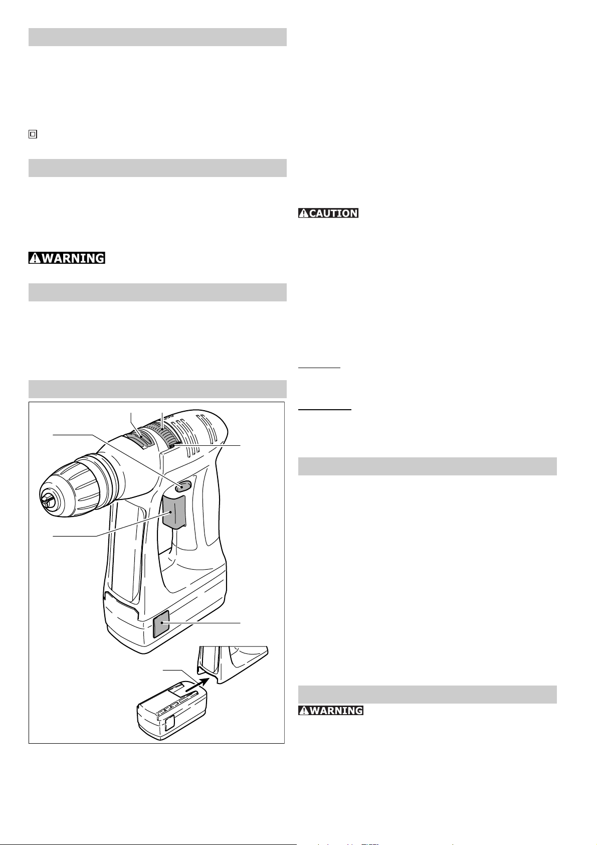
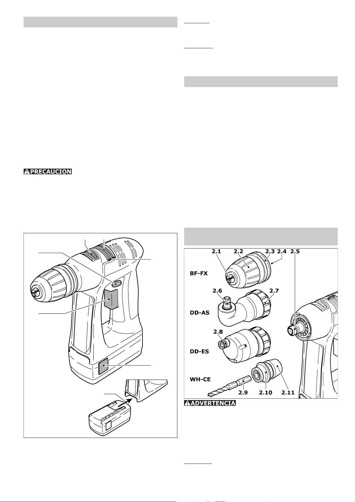
Machine settings
1.3 1.4
1.2
1.5
- Inserting battery pack: Slide the battery pack
into the holder on the underside of the handle
until it latches into place (1.7).
To change the direction of rotation
The selector button (1.2) determines the direction
of rotation.
• Turn button from right to left = clockwise rotation.
• Turn button from left to right = anticlockwise
rotation.
• Selector button in central position = circuit interlock.
Shifting speeds
Change only when completely
stopped!
Using the shift lever (1.3), the speed can be
changed.
• 1. Speed: Lever forward - Figure 1 is visible.
• 2. Speed: Lever backwards - Figure 2 is vis-
ible.
Torque adjustment
By turning the adjustment ring (1.4) the required
torque can be adjusted. The arrow (1.5) aligns
with the adjusted state.
Drilling:
Drilling symbol on adjustment ring aligns with the
arrow = maximum torque.
Screwing:
Torque corresponding to setting:
• Position 1 = low torque
• Position 20 = high torque
1.1
1.6
1.7
Exchanging the battery pack
- Removing battery pack: Press the two buttons
(1.6) and slide the battery pack forwards to
remove.
Operation
Turn on by pressing button (1.1). Depending on
the pressure exerted on the button, the adjustment of running speed can be varied infi nitely.
Turn off by releasing the button (1.1). After releasing the button, the chuck is stopped and therefore,
after-running of the equipment is prevented.
Warning signal
With the following operational statuses, the
machine sounds an acoustic warning signal and
switches off:
Peep at regular intervals
- Battery empty
Triple peep at regular intervals
- Excessive load (torque)
- Machine too warm.
Tool holding fi xture, attachments
Make sure that the machine is
switched of and the battery block has been removed before changing the tool holding fi xture,
attachments and tools.
4
Page 5
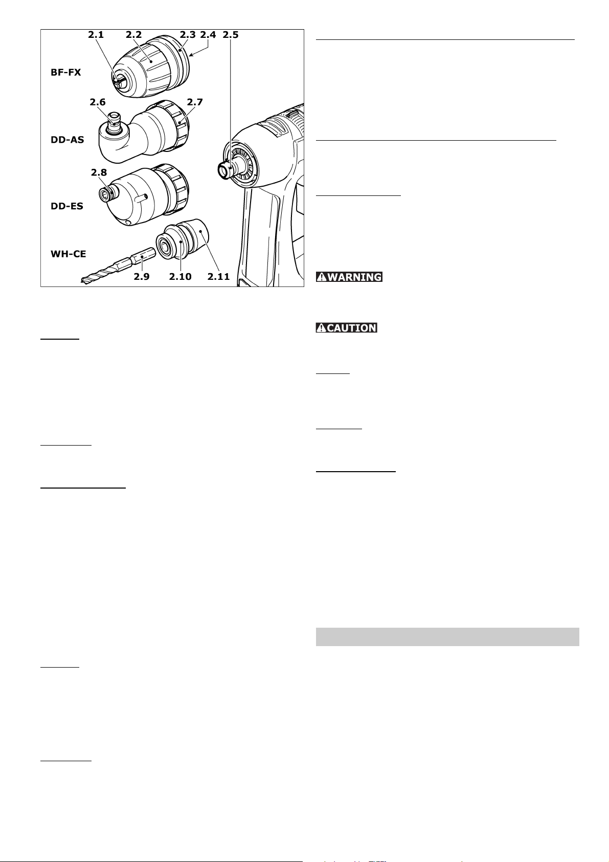
Chuck BF-FX
The chuck is used to clamp drills and bits.
Fitting:
- Place the chuck on the drill spindle (2.5) and
twist until the hexagon key (2.4) of the chuck
latches into the hexagon socket of the drill
spindle.
- Pull the unlocking ring (2.3) forwards, press the
chuck onto the drill spindle up to the stop and
release the unlocking ring.
Removal:
- Pull the unlocking ring forwards and remove
the chuck.
Changing tools:
- Turn the clamping sleeve (2.2) anti-clockwise
to open the clamping jaws (2.1)
(Note: the spindle is automatically locked when
the machine is switched off).
- Insert the tool into the chuck.
- Clamp the tool by turning the clamping sleeve
clockwise. Always make sure that the tool is
clamped centrally in the chuck.
Angle attachment DD-AS
The angle attachment permits work (drilling,
screwing) vertical to the machine’s longitudinal
axis.
Fitting:
- Place the angle attachment on the drill spindle
and turn until it catches in the desired position
(Note: The angle attachment can be fi tted in
16 different angle settings).
- Lock the angle attachment by turning the fastening ring (2.7) tightly clockwise.
Removal:
- Turn the fastening ring anti-clockwise up to the
stop and remove the angel attachment.
Fitting / removal of chuck on angle attach ment:
The chuck is fi tted on the shaft (2.6) of the angle
attachment in the same way as on the drill spindle
of the machine.
Eccentric attachment DD-ES
The eccentric attachment is used to hold bits. It
allows screwing close to edges.
Fitting / removing the eccentric attach ment:
The eccentric attachment is fi tted / removed in
the same was as the angle attachment (see DDAS).
Changing tools:
Pull the unlocking ring (2.8) back and remove the
tool and/or insert the new tool.
CENTROTEC WH-CE toolholder
The CENTROTEC toolholder enables rapid changes
of tools with CENTROTEC shafts.
Danger of injury! When changing
tools, handle the tool and its sharp cutters with
special care and wear protective gloves, if necessary.
Do not fi t CENTROTEC tools at the
round shaft section in a conventional chuck to
prevent damage to the shaft.
Fitting
- Pull the release ring (2.11) forwards, place the
toolholder as far as it will go on the drill spindle
(2.5) and let go of the release ring.
Removal
- Pull the release ring forwards and take off the
toolholder.
Changing tools
- To insert or remove a tool with CENTROTEC
shaft, pull the green release ring (2.10) back.
On inserting the tool, turn it until its hex shank
arbour (2.9) locks in place in the hexagonal
shank of the drill spindle, and push the tool into
the toolholder as far as it will go.
Tool holding fi xture in the drill
spindle
Bits can be fi tted directly in the hexagon socket
holder of the drill spindle (2.5) to make the machine lighter and shorter.
Charge battery pack
To load the battery pack, push it into the holder
(3.1) on the charger up to the stop. Perform this
in reverse to remove the battery pack from the
charger.
The battery type used (NiCd or NiMH) is detected
automatically. Charging is controlled by a microprocessor.
If a warm NiMH battery pack (>37° C) is inserted, charging will only be carried out at a lower
charge current. In this case, the charging time is
extended.
5
Page 6
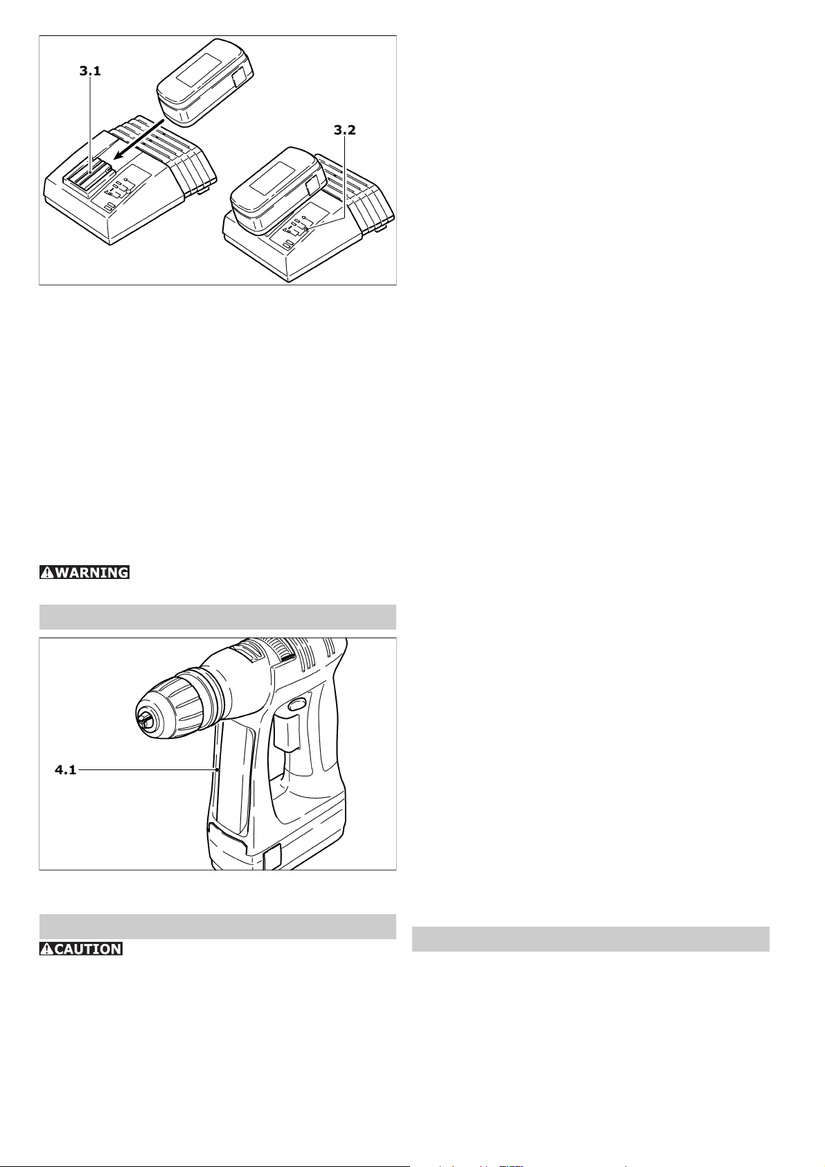
The LED (3.2) indicates the respective charging state of the charger.
LED yellow – steady:
charger is ready for use.
LED green – fl ashing:
battery pack being charged.
LED green – steady:
battery pack fully charged, conservation charge
on.
LED red – fl ashing:
general malfunction, e. g. full contact not being
made, short-circuit, battery pack faulty.
LED red – steady:
temperature of battery pack is outside permis-
sible limit.
It is essential that you read the in-
structions in the Chapter „Maintenance - Care“.
Bit storage well
You can insert several bits or bit extensions into
the bit magazine (4.1) with magnetic holder.
Maintenance and care
Pay attention to the following instructions. Otherwise there is a risk of damage to the
tool, charger or battery pack.
• Repairs may only be performed by authorised
technicians. LC 45 charging device: Even after
disconnection from the mains, there is still a
high capacitor voltage on the power output
component on the inside of the device.
• Keep the air vents of the electronic equipment
and the charger clean to guarantee the air circulation for cooling.
• No metal objects (metal chips) should enter the
charger at the contact points as well as through
the cooling slits into the equipment (danger of
short circuit).
• Only use original Festool battery packs. Do not
use spent and recycled battery packs. The user
shall be liable for damages if Festool original
battery packs are not used.
• Keep the connection contacts of electronic
equipment, charger and battery pack clean.
• By keeping the battery pack in a ready for use
charger, the battery pack will be kept in a state
of readiness by fl oat charging conservation.
• Do not keep discharged battery pack (maximum
one month) attached to charger whenever charger is detached from the power supply (danger
of deep discharging).
• A new battery pack or a battery pack not used
for a longer period of time reaches it full capacity after about 5 charging and discharging
cycles.
• Battery packs should, before charging, be fully
discharged if possible. Continuous starting of
the charging process shortens the lifespan of
the batteries.
• A considerably reduced time of operation per
charging shows that the battery pack is used
up an should be replaced by a new one.
• NiCd battery packs that are not used for longer periods should be stored in a discharged
state.
Special instructions for NiMH battery
packs:
• The output of NiMH battery packs drops noticeably at ambient temperatures below 0° C or
above 45° C.
• Do not overload the tool (do not load the tool
excessively so that it comes to a standstill).
• Even if NiMH battery packs are not used, recharge them approx. every 4 months so that
they retain their full capacity.
• NiMH battery packs should be left for 60 min.
in the charger after every 10th fast charge to
compensate any differences in capacity between the cells.
• Because NiMH battery packs discharge automatically, store them preferably at ambient
temperatures of between 0° C and 25° C.
Recycling battery packs
Never throw spent battery packs into domestic waste containers! Return spent or defective
battery packs to dealers, the Festool after-sales
service department or approved waste disposal
facilities. This ensures that they are correctly
recycled.
6
Page 7

Accessories, tools
For safety reasons, only use original
Festool accessories and tools!
The accessory and tool order number can be found
in your Festool catalog or on the Internet at www.
festool-usa.com.
Warranty
Conditions of 1+2 Warranty
You are entitled to a free extended warranty (1
year + 2 years = 3 years) for your Festool power
tool. Festool shall be responsible for all shipping
costs during the fi rst year of the warranty. During the second and third year of the warranty the
customer is responsible for shipping the tool to
Festool. Festool will pay for return shipping to the
customer using UPS Ground Service. All warranty
service is valid 3 years from the date of purchase
on your receipt or invoice.
Festool Limited Warranty
This warranty is valid on the pre-condition that the
tool is used and operated in compliance with the
Festool operating instructions. Festool warrants,
only to the original consumer purchaser, that the
specifi ed tool will be free from defects in materials and workmanship for a term of one year from
the date of procurement. Festool makes no other
warranty, express or implied, for Festool portable
power tools. No agent, representative, distributor,
dealer or employee of Festool has the authority
to increase or otherwise change the obligations
or limitations of this warranty. The obligations of
Festool in its sole discretion under this warranty
shall be limited to the repair or replacement of
any Festool portable power tool that is found to be
defective as packaged with the User Manual.
Excluded from coverage under this warranty are:
normal wear and tear; damages caused by misuse,
abuse or neglect; damage caused by anything
other than defects in material and workmanship.
This warranty does not apply to accessory items
such as circular saw blades, drill bits, router bits,
jigsaw blades, sanding belts, and grinding wheels.
Also excluded are “wearing parts”, such as carbon
brushes, lamellas of air tools, rubber collars and
seals, sanding discs and pads, and batteries.
Festool portable power tools requiring replacement
or repair are to be returned with the receipt of
purchase to Festool (call 800-554-8741 for address details).
IN NO EVENT SHALL FESTOOL BE LIABLE
FOR ANY CONSEQUENTIAL OR INCIDENTAL
DAMAGES FOR BREACH OF THIS OR ANY
OTHER WARRANTY, EXPRESSED OR IMPLIED
WHATSOEVER. ALL WARRANTIES IMPLIED
BY STATE LAW, INCLUDING THE IMPLIED
WARRANTIES OF MERCHANTABILITY AND
FITNESS FOR A PARTICULAR PURPOSE, ARE
HEREBY LIMITED TO THE DURATION OF
THREE YEARS.
Some states in the U.S. and some Canadian provinces do not allow the limitations on how long an
implied warranty lasts, so the above limitation may
not apply to you. With the exception of any warranties implied by state or province law as hereby
limited, the foregoing express limited warranty
is exclusive and in lieu of all other warranties,
guarantees, agreements and similar obligations
of Festool.
This warranty gives you specifi c legal rights and
you may also have other rights which vary from
state to state in the U.S. and province to province
in Canada.
7
Page 8

RÈGLES DE SÉCURITÉ GÉNÉRALES
Assurez-vous de lire et de
bien com prendre toutes les instructions. Le
non-respect, même partiel, des instructions cidessous peut entraîner un risque de choc électrique, d’incendie et/ou de blessures graves.
CONSERVEZ CES INSTRUCTIONS
1) Sécurité de aire de travail
a) Maintenez l’endroit de travail propre et
bien éclairé. Un lieu de travail en désordre ou
mal éclairé augmente le risque d’accidents.
b) N’utilisez pas l’appareil dans un environnement présentant des risques d’explosion et
où se trouvent des liquides, des gaz ou poussières infl ammables. Les outils électroportatifs
génèrent des étincelles risquant d’enfl ammer les
poussières ou les vapeurs.
c) Tenez les enfants et autres personnes
éloignés durant l’utilisation de l’outil électroportatif. En cas d’inattention vous risquez de
perdre le contrôle sur l’appareil.
2) Sécurité électrique
a) La fi che de secteur de l’outil électroportatif doit être appropriée à la prise de courant.
Ne modifi ez en aucun cas la fi che. N’utilisez
pas de fi ches d’adaptateur avec des appareils
avec mise à la terre. Les fi ches non modifi ées
et les prises de courant appropriées réduisent le
risque de choc électrique.
b) Evitez le contact physique avec des surfaces mises à la terre tels que tuyaux, radiateurs, fours et réfrigérateurs. Il y a un risque
élevé de choc électrique au cas où votre corps
serait relié à la terre.
c) N’exposez pas l’outil électroportatif à la
pluie ou à l’humidité. La pénétration d’eau dans
un outil électroportatif augmente le risque d’un
choc électrique.
d) N’utilisez pas le câble à d’autres fi ns que
celles prévues, n’utilisez pas le câble pour
porter l’appareil ou pour l’accrocher ou encore pour le débrancher de la prise de courant. Maintenez le câble éloigné des sources
de chaleur, des parties grasses, des bords
tranchants ou des parties de l’appareil en
rotation. Un câble endommagé ou torsadé aug-
mente le risque d’un choc électrique.
e) Au cas où vous utiliseriez l’outil électro-
portatif à l’extérieur, utilisez une rallonge
autorisée homologuée pour les applications
extérieures. L’utilisation d’une rallonge électri-
que homologuée pour les applications extérieures
réduit le risque d’un choc électrique.
f) Ne tenez l‘outil qu‘à l‘aide des poignées
isolées, lorsque vous êtes susceptibles de
toucher des lignes électriques cachées ou
votre propre câble électrique, lorsque vous
travaillez avec des outils de tronçonnage. Si
des outils de tronçonnage touchent des lignes électriques, des pièces métalliques de l‘outil peuvent
être mises sous tension et asséner une décharge
électrique à l‘utilisateur.
3) Sécurité des personnes
a) Restez vigilant, surveillez ce que vous
faites. Faites preuve de bon en utilisant
l’outil électroportatif. N’utilisez pas l’appareil lorsque vous êtes fatigué ou après avoir
consommé de l’alcool, des drogues ou avoir
pris des médicaments. Un moment d’inattention
lors de l’utilisation de l’appareil peut entraîner de
graves blessures sur les personnes.
b) Portez des équipements de protection.
Portez toujours des lunettes de protection.
Le fait de porter des équipements de protection
personnels tels que masque anti-poussières,
chaussures de sécurité antidérapantes, casque
de protection ou protection acoustique suivant le
travail à effectuer, réduit le risque de blessures.
c) Evitez une mise en service par mégarde.
Assurez-vous que l’interrupteur est effectivement en position d’arrêt avant de retirer
la fi che de la prise de courant. Le fait de porter
l’appareil avec le doigt sur l’interrupteur ou de
brancher l’appareil sur la source de courant lorsque
l’interrupteur est en position de fonctionnement,
peut entraîner des accidents.
d) Enlevez tout outil de réglage ou toute clé
avant de mettre l’appareil en fonctionnement. Une clé ou un outil se trouvant sur une
partie en rotation peut causer des blessures.
e) Ne surestimez pas vos capacités. Veillez
à garder toujours une position stable et
équilibrée. Ceci vous permet de mieux contrôler
l’appareil dans des situations inattendues.
f) Portez des vêtements appropriés. Ne portez pas de vêtements amples ni de bijoux.
Maintenez cheveux, vêtements et gants
éloignés des parties de l’appareil en rotation. Des vêtements amples, des bijoux ou des
cheveux longs peuvent être happés par des pièces
en mouvement.
g) Si des dispositifs servant à aspirer ou à
recueillir les poussières doivent être utilisés,
vérifi ez que ceux-ci soient effectivement raccordés et qu’ils sont correctement utilisés.
L’utilisation de tels dispositifs réduit les dangers
dus aux poussières.
4) Utilisation et entretien des outils
a) Ne surchargez pas l’appareil. Utilisez
l’outil électroportatif approprié au travail à
effectuer. Avec l’outil électroportatif approprié,
vous travaillerez mieux et avec plus de sécurité à
la vitesse pour laquelle il est prévu.
b) N’utilisez pas un outil électroportatif dont
l’interrupteur est défectueux. Un outil élec-
troportatif qui ne peut plus être mis en ou hors
fonctionnement est dangereux et doit être réparé.
c) Retirer la fi che de la prise de courant avant
d’effectuer des réglages sur l’appareil, de
changer les accessoires, ou de ranger l’appareil. Cette mesure de précaution empêche une
mise en fonctionnement par mégarde.
8
Page 9

d) Gardez les outils électroportatifs non utilisés hors de portée des enfants. Ne permettez
pas l’utilisation de l’appareil à des personnes
qui ne se sont pas familiarisées avec celui-ci
ou qui n’ont pas lu ces instructions. Les outils
électroportatifs sont dangereux lorsqu’ils sont
utilisés par des personnes non initiées.
e) Prenez soin des outils électroportatifs.
Vérifi ez que les parties en mouvement fonctionnent correctement et qu’elles ne soient
pas coincées, et contrôlez si des parties sont
cassées ou endommagées de telle sorte que
le bon fonctionnement de l’appareil s’en
trouve entravé. Faites réparer les parties
endommagées avant d’utiliser l’appareil. De
nombreux accidents sont dus à des outils électroportatifs mal entretenus.
f) Maintenez les outils de coupe aiguisés et
propres. Des outils soigneusement entretenus
avec des bords tranchants bien aiguisés se coincent moins souvent et peuvent être guidés plus
facilement.
g) Utilisez les outils électroportatifs, les accessoires, les outils à monter etc. conformément à ces instructions et aux prescriptions
en vigueur pour ce type d’appareil. Tenez
compte également des conditions de travail
et du travail à effectuer. L’utilisation des outils
électroportatifs à d’autres fi ns que celles prévues
peut entraîner des situations dangereuses.
5) Utilisation et emploi soigneux
des appareils sans fi l
a) Vérifi ez que l‘appareil est effectivement en
position d‘arrêt avant de monter l‘accumulateur. Le fait de monter un accumulateur dans un
outil électroportatif en position de fonctionnement
peut causer des accidents.
b) Ne chargez les accumulateurs que dans
des chargeurs recommandés par le fabricant.
Un chargeur approprié à un type spécifi que d‘accumulateur peut engendrer un risque d‘incendie
lorsqu‘il est utilisé avec d‘autres accumulateurs.
c) Dans les outils électroportatifs, n‘utilisez
que les accumulateurs spécialement prévus
pour celui-ci. L‘utilisation de tout autre accumu-
lateur peut entraîner des blessures et des risques
d‘incendie.
d) Tenez l‘accumulateur non-utilisé à l‘écart
de toutes sortes d‘objets métalliques tels
qu‘agrafes, pièces de monnaie, clés, clous,
vis ou autres, étant donné qu‘un pontage
peut provoquer un court-circuit. Un court-cir-
cuit entre les contacts d‘accu peut provoquer des
brûlures ou un incendie.
e) En cas d‘utilisation abusive, du liquide
peut sortir de l‘accumulateur. Evitez tout
contact avec ce liquide. En cas de contact
par mégarde, rincez soigneusement avec de
l‘eau. Au cas où le liquide rentrerait dans les
yeux, consultez en plus un médecin. Le liquide
qui sort de l‘accumulateur peut entraîner des irritations de la peau ou causer des brûlures.
6) Entretien et réparation
a) Ne faites réparer votre outil électroportatif que par un personnel qualifi é et seulement
avec des pièces de rechange d’origine. Ceci
permet d’assurer la sécurité de l’appareil.
Pour réduire le risque de
dommages, l'utilisateur doit lire et comprendre le manuel d'instruction.
Certaines poussières créées par le ponçage mécanique, le sciage, le meulage,
le perçage et autres activités reliées à la construction contiennent des substances chimiques connues (dans l’État de la Californie) comme pouvant causer le cancer, des anomalies congénitales ou
représenter d’autres dangers pour la reproduction. Voici quelques exemples de telles substances:
• plomb provenant de peintures à base de plomb,
• silice cristallisée utilisée dans les briques, le ciment et autres matériaux de maçonnerie, et
• arsenic et chrome du bois d’œuvre traité avec un produit chimique.
Le risque d’exposition à de tels produits varie selon la fréquence à laquelle vous faites
ce genre de travail. Pour réduire les risques d’exposition à ces substances chimiques:
travaillez dans un endroit adéquatement ventilé et utilisez un équipement de sécurité
approuvé, tel que masques antipoussières spécialement conçus pour fi ltrer les particules microscopiques.
Caractéristiques techniques
Perceuse-visseuse C 12
Tension du moteur 12 V
Vitesse à vide: 1 ère vitesse / 2 ème vitess 0 – 450 tr/min / 0 – 1500 tr/min
Couple max.: vissage faciles / vissage diffi ciles 18 Nm / 30 Nm
Réglage de couple: 1 ère vitesse / 2 ème vites 2 – 7 Nm / 0.5 – 2.5 Nm
Capacité mandrin 1.5 – 13 mm
Maxi capacité de perçage, métal / bois 14 mm / 25 mm
Fixation de la broche 1/4 "
Poids sans accumulateur 0.96 kg (2.1 lbs)
9
Page 10

Chargeur LC 45
Tension / fréquence secteur (entrée) 120 V ~ / 60 Hz
Tension de charge (sortie) 7.2 - 18 V (DC)
Courant de charge: • Charge rapide 3 A max.
• Charge de maintien à impulsions 0.06 A env.
Durée de charge pour: • NiCd 1.3 Ah 30 min env.
• NiCd 2.4 Ah 50 min env.
• NiMH 3.0 Ah 70 min env.
Accumulateur BPS 12 C NiCd BPS 12 S NiCd BPS 12 S NiMH
Référence 493 348 492 268 491 821
Tension 12 V 12 V 12 V
Capacité 1.3 Ah 2.4 Ah 3.0 Ah
Plage de temp. de charge 5 - 45 °C 5 - 45 °C 5 - 45 °C
Contrôle d’état de charge via résistance NTC
Poids 0.56 kg (1.2 lbs) 0.73 kg (1.6 lbs) 0.75 kg (1.7 lbs)
Symbole
V Volt
A Ampère
Hz Hertz
W Watt
~ Tension alternative
n
Vitesse de rotation à vide
0
Classe II conception
tr/min tours par minute
Utilisation prévue
La perceuse-visseuse sans fi l est adaptée au perçage du métal, du bois, des plastiques et matériaux similaires, ainsi qu’au vissage (vis jusqu’à
un diamètre de 6 mm dans le bois).
Le chargeur LC 45 convient au chargement de la
batterie utilisée.
Seul l’utilisateur est tenu
responsable des dommages qui résulteraient d’une
utilisation non conforme aux prescriptions.
Fixation au mur LC 45
Le chargeur LC 45 dispose sur son dos de deux
trous oblongs par l’intermédiaire desquels il peut
être fi xé au mur par deux vis (par ex. vis à tête
conique ou ronde avec un diamètre de la partie
lisse de la tige de 5 mm). Vissez les deux vis en
respectant un intervalle de 96 mm au mur, de
manière à ce qu’il reste encore un espace de 4
mm entre la tête de vis et le mur.
• Bouton poussé de droite vers la gauche = marche à droite.
• Bouton poussé de gauche vers la droite = marche à gauche.
• Bouton en position centrale = verrouillage de
mise en marche.
1.3 1.4
1.2
1.5
1.1
1.6
1.7
Réglages de la machine
Remplacer la batterie
- Retrait de la batterie : appuyez sur le deux
touches (1.6), et enlevez la batterie en la tirant
vers l’avant.
- Installation de la batterie : enfoncez la batterie
dans le logement par le dessous de la poignée
jusqu’à ce qu’elle soit bien enclenchée (1.7).
Commutation du sens de rotation
Le bouton de commutation (1.2) sert à déterminer
le sens de rotation.
Commutation de l’engrenage
Procéder à la commutation uni-
quement à l’arrêt ou en fi n de roulement!
Le curseur de commutation (1.3) permet de com-
muter l’engrenage.
• 1ère vitesse: Curseur de commutation vers
l’avant - le chiffre 1 est visible.
• 2ème vitesse: Curseur de commutation vers
l’arrière - le chiffre 2 est visible.
10
Page 11

Réglage du couple de rotation
Il est possible de faire varier le couple de rotation
en tournant la bague de réglage (1.4). La fl èche
apposée (1.5) indiquera l’état réglé.
Perçage
Couple de rotation maximal - la fl èche est pointée
sur le symbole de perçage
Vissage
Couple de rotation en fonction du réglage:
• Position sur 1 = couple de rotation réduit
• Position sur 20 = couple de rotation élevé
Utilisation
Mise en marche en appuyant sur la touche de commutation (1.1). La vitesse de rotation peut être
progressive-ment réglée, en fonction du mode de
pression sur la touche de commutation.
Mise à l’arrêt en relâchant la touche de commutation (1.1). Une fois que la touche de commutation
est relâchée, la broche de travail (mandrin) est
freinée, ce qui empêche ainsi une poursuite de
rotation par inertie de l’outil.
Signal d’alerte
Dans les situations de fonctionnement suivantes,
la machine émet un signal d’alerte et s’arrête :
Bip sonore intermittent
- Batterie déchargée
3 bips sonores intermittents
- Charge (couple) trop importante
- Machine trop chaude.
Porte-outil, groupes d’appui
Montage :
- Placez le mandrin de perceuse sur l'axe (2.5)
puis tournez-le jusqu'à ce que le six pans (2.4)
du mandrin de perceuse s'enclenche dans le
logement de l'axe.
- Tirez la bague de déverrouillage (2.3) vers
l'avant, enfoncez le mandrin de perceuse jusqu'à la butée sur l'axe puis relâchez la bague
de déverrouillage.
Démontage :
- Tirez la bague de déverrouillage vers l'avant
puis enlevez le mandrin de perceuse.
Changement d'outil :
- Tournez la douille de serrage (2.2) dans le sens
contraire des aiguilles d'une montre pour ouvrir
les mâchoires de serrage (2.1)
(Remarque : A machine inactivée, l'axe est
automa-tiquement verrouillé).
- Placez l'outil dans le mandrin de perceuse.
- Serrez l'outil à fond en tournant la douille de
serrage dans le sens des aiguilles d'une montre.
Ce faisant, veillez toujours à ce que l'outil soit
serré au centre du mandrin.
Appui angulaire DD-AS
L'appui angulaire permet de travailler (percer, visser) à la verticale par rapport à l'axe longi-tudinal
de la machine.
Montage :
- Placez l'appui angulaire sur l'axe et tournez-le
jusqu'à ce qu'il s'enclenche dans la position
souhaitée (Remarque : L'appui angulaire peut
s'enclencher dans 16 positions angulaires différentes).
- Verrouillez l'appui angulaire en tournant fermement la bague de fi xation (2.7) dans le sens
des aiguilles d'une montre.
Démontage :
- Tournez la bague de fi xation dans le sens contraire des aiguilles d'une montre jusqu'à la
butée puis enlevez l'appui angulaire.
Montage / démontage du mandrin de perceuse
sur l'appui angulaire :
Le mandrin de perceuse doit être fi xé de la même
manière sur l'arbre (2.6) de l'appui angu-laire que
sur l'axe de la machine.
A chaque remplacement du
porte-outil, du groupe d’appui et de l’outil, assurez-vous que la machine est convenablement
inactivée et que l’accumulateur est enlevé.
Mandrin de perceuse BF-FX
Le mandrin de perceuse sert à serrer les forets et
les embouts.
Appui excentrique DD-ES
L'appui excentrique sert à la réception d'embouts.
Il permet de visser à proximité du bord.
Montage / démontage de l'appui excentrique :
Le montage / démontage de l'appui excentrique
s'opère de la même manière que pour l'appui angulaire (cf. DD-AS).
Changement d'outil
- Tirez la bague de déverrouillage (2.8) vers
l'arrière puis enlevez l'outil ou resp. mettez un
outil en place.
11
Page 12

Porte-outil CENTROTEC-WH-CE
Le porte-outil CENTROTEC permet un changement rapide d’outils avec arbre CENTROTEC.
Risque de blessure ! Mani pulez
très prudemment l’outil aux arêtes tranchan tes
lorsque vous procédez à un échange d’outil, portez
éventuelle-ment des gants de protection.
Ne serrez pas les outils CENTROTEC au niveau du manche dans un mandrin
de serrage traditionnel pour ne pas endommager
le manche.
Montage
- Tirez la bague de déverrouillage (2.11) vers
l’avant, enfoncez le porte-outil jusqu’en butée
sur l’axe (2.5) puis relâchez la bague de déverrouillage.
Démontage
- Tirez la bague de déverrouillage vers l’avant et
enlevez le porte-outil.
Changement d’outillage
- Pour placer ou enlever un outil avec arbre CEN-
TROTEC, retirez sur la bague de déverrouillage
verte (2.10). Pour mettre un outil en place,
tournez jusqu’à ce que son arbre hexagonal
(2.9) s’engage dans le logement hexagonal de
l’axe et poussez l’outil à fond dans le porteoutil.
La DEL (3.2) indique à chaque fois l’état de
service du chargeur.
DEL jaune - éclairage continu:
le chargeur est prêt à fonctionner.
DEL verte - éclairage clignotant:
L’accumulateur est en train d’être chargé.
DEL verte - éclairage continu:
L’accumulateur est chargé; la charge de main-
tien est active.
DEL rouge - éclairage clignotant:
indication d’erreur générale, par exemple pas
de mise en contact complète, court-circuit,
défectuo-sité de l’accumulateur
DEL rouge - éclairage continu:
température de l’accumulateur au-delà des
valeurs limites admissibles.
Nous vous recommandons de
respecter les instructions décrites dans le chapitre
intitulé „Entretien - Maintenance“.
Bit-Depot
Porte-outil sur l'axe
Afi n que la machine devienne plus légère et plus
courte, les embouts peuvent être mis en place
directement dans le logement six pans de l'axe
(2.5).
Charger l’accumulateur
Pour le chargement, vous devez pousser la batterie dans le logement (3.1) du chargeur jusqu’à
la butée. A l’inverse, il est possible de retirer la
batterie chargée du chargeur.
Le type d’accumulateur utilisé (NiCd ou NiMH)
est identifi é automatiquement. La procédure de
charge est contrôlée par microprocesseur.
Si vous utilisez un pack d’accumulateurs NiMH
chaud (>37°C), il sera seulement chargé avec un
courant de charge réduit. Dans ce cas, le temps
de charge sera prolongé.
Les porte-embouts (4.1) à support magnétique
peuvent accueillir plusieurs embouts ou prolongateurs.
Entretien - Maintenance
Il est indispensable d’obser-
ver les consignes suivantes, sinon, la machine,
le chargeur ou l’accumulateur risque d’être
endommagé(e).
• Les réparations doivent être uniquement réa-
lisées par un spécialiste. Dans le chargeur LC
45, la tension au condensateur à l’intérieur de
l’appareil reste élevée même après le débranchement du réseau.
• Veiller à ce que les ouvertures d’aération sur
l’outil électrique et sur le chargeur soient toujours propres afi n que la circulation de l’air de
refroidissement soit assurée.
• Sur le chargeur, aucune pièce métallique (co-
peaux métalliques) ne doit pénétrer dans les
compartiments de réception des accumulateurs
et par les fentes d’aération (risque de courtcircuit).
• N’utiliser que des accumulateurs d’origine Fes-
tool et ne pas utiliser non plus d’accumulateurs
usagés ou remis en état. En effet, seul l’utilisateur sera tenu responsable en cas d’apparition
12
Page 13

de dommages résultant d’une violation de cette
prescription.
• Veiller à ce que les contacts de raccordement
sur l’outil électrique, sur le chargeur et sur
l’accu-mulateur soient toujours propres.
• En laissant l’accumulateur dans le chargeur prêt
à fonctionner, l’accumulateur est conservé en
état chargé grâce à un chargement de maintien
permanent.
• Ne pas laisser les accumulateurs vides enfi chés
pendant plus d’un mois env. dans le chargeur
lorsque le chargeur est coupé du secteur (risque
de décharge profonde).
• Un accumulateur neuf ou n’ayant pas été utilisé
pendant une longue période n’atteint sa pleine
capacité qu’au bout de 5 cycles de charge et
de décharge environ.
• Il faudrait, dans la mesure du possible, que les
accumulateurs soient entièrement déchargés
avant d’être rechargés. En effet, un démarrage
réitéré de l’opération de charge d’accumulateurs chargés diminue leur durée de vie.
• Une durée de fonctionnement considérable ment
plus réduite à la suite de chaque recharge indique que l’accumulateur est usé et qu’il doit par
conséquent être remplacé par un neuf.
• Les batteries NiCd, qui ne sont pas utilisées
pendant une période plus longue, doivent être
rangées dans leur état déchargé.
Consignes particulières concernant les accumulateurs NiMH :
• En présence de températures ambiantes inférieures à 0° C ou supérieures à 45° C, la
puissance des accumulateurs NiMH diminue
nettement.
• Ne pas surcharger la machine (ne pas solliciter
la machine à un tel point qu’elle s’immobilise).
• Chargez les batteries NiMH environ tous les
4 mois, même en cas de non-utilisation, afi n
d’exploiter au mieux toute leur capacité.
• Après chaque 10ème cycle de charge, les packs
d’accumulateurs NiMH doivent rester 60 min
supplémentaires dans le chargeur après la
charge rapide, afi n de compenser d’éventuelles
différences de capacité entre les éléments.
• Rangez de préférence les batteries NiMH, suite
à leur déchargement, à des températures ambiantes comprises entre 0° C et 25° C.
Recyclage des accumulateurs
Ne pas jeter les accumulateurs usagées dans
les ordures ménagères. Les accumulateurs
usagés ou défectueux doivent être rendus aux
revendeurs, au service après-vente Festool ou aux
installations d’élimination publiques prescrites. Les
accumulateurs seront ainsi soumis à un recyclage
approprié.
Accessoires, outils
Pour des raisons de sécurité,
il faut utiliser exclusivement des accessoires et
outils d’origine Festool!
Les références des accessoires et outils fi gurent
dans le catalogue Festool ou sur Internet sous
www.festool-usa.com.
Garantie
Conditions de la garantie (1+2 ans)
Vous avez droit à une prolongation de garantie
gratuite (1 an + 2 ans = 3 ans) sur votre outil
électrique Festool. Festool assumera tous les
coûts d’expédition pendant la première année de
la garantie alors que les deuxième et troisième
années, les coûts devront être assumés par le
client. Festool paiera les frais de retour de l’outil
au client par service de livraison terrestre UPS.
La garantie est valable pour une période de 3 ans
à compter de la date d’achat indiquée sur votre
reçu ou votre facture.
Garantie limitée de Festool
Cette garantie est valable à condition que l’outil
soit utilisé conformément aux instructions de
Festool. Festool garantit, à l’acheteur initial seulement, que l’outil indiqué sera exempt de tout
défaut de matériau et de fabrication pendant un
an à compter de la date d’achat. Festool ne donne
aucune garantie supplémentaire, implicite ou explicite, sur les instruments portables électriques
Festool. Aucun agent, représentant commercial,
distributeur, vendeur ou employé de Festool n’est
autorisé à prolonger ou à modifi er les obligations
ou restrictions de la présente garantie. Les obligations de Festool sont, à son entière discrétion,
limitées à la réparation ou à l’échange des outils
portables électriques Festool trouvés défectueux
dans le présent emballage, tels que fournis avec
le présent Guide d’utilisation.
Cette garantie exclut l’usure normale, les dommages causés par un usage impropre, les abus
ou la négligence, ou tout dommage autre que
ceux attribuables à des défauts de matériau et
de fabrication. Cette garantie ne s’applique pas
aux accessoires tels que lames de scie circulaire,
mèches de perceuse et vilebrequin, lames de scie
sauteuse, bandes abrasives et meules. Sont également exclues les pièces d’usure, telles que balais
de charbon, lamelles pour outils à air comprimé,
joints et manchons de caoutchouc, disques et
patins ponceurs, ainsi que les piles.
Les outils électriques portables Festool à remplacer
ou à réparer doivent être retournés avec le reçu
d’achat à Festool (appelez au 800-554-8741 pour
connaître l’adresse d’expédition).
FESTOOL N’EST EN AUCUN CAS RESPONSABLE
DES DOMMAGES DIRECTS OU INDIRECTS,
IMPLICITES OU EXPLICITES, DÉCOULANT
DE LA RUPTURE DE CETTE GARANTIE OU
DE TOUTE AUTRE GARANTIE. TOUTES
13
Page 14

LES GARANTIES IMPLICITES, Y COMPRIS
LES GARANTIES IMPLICITES DE QUALITÉ
MARCHANDE ET D’ADÉQUATION À UN
USAGE PARTICULIER, SONT LIMITÉES À UNE
PÉRIODE DE TROIS ANS.
Certains états américains et certaines provinces
canadiennes ne permettent pas la limitation des
garanties implicites; il se pourrait donc que les
limites indiquées ci-dessus ne s’appliquent pas
dans votre cas. À l’exception de certaines garanties
implicites des provinces ou des états indiquées
ici, la présente garantie est exclusive et remplace
toute autre garantie, convention et obligation similaire de Festool.
Cette garantie vous confère des droits légaux
spécifi ques, et vous pouvez aussi avoir d’autres
droits pouvant varier d’un état à l’autre, ou d’une
province à l’autre au Canada.
NORMAS GENERALES DE SEGURI-
DAD
Lea y entienda todas las ins-
trucciones. El incumplimiento con las instruccio-
nes aquí referidas puede resultar en una descarga
eléctrica, fuego y/o lesiones personales serias.
CONSERVE ESTAS INSTRUCCIONES
1) Seguridad del espacio de trabajo
a) Mantenga limpio y bien iluminado su puesto de trabajo. El desorden y una iluminación
defi ciente en las áreas de trabajo pueden provocar
accidentes.
b) No utilice la herramienta eléctrica en un
entorno con peligro de explosión, en el que
se encuentren combustibles líquidos, gases
o material en polvo. Las herramientas eléctricas
producen chispas que pueden llegar a infl amar los
materiales en polvo o vapores.
c) Mantenga alejados a los niños y otras personas de su puesto de trabajo al emplear la
herramienta eléctrica. Una distracción le puede
hacer perder el control sobre el aparato.
2) Seguridad eléctrica
a) El enchufe del aparato debe corresponder a la toma de corriente utilizada. No es
admisible modifi car el enchufe en forma alguna. No emplear adaptadores en aparatos
dotados con una toma de tierra. Los enchufes
sin modifi car adecuados a las respectivas tomas
de corriente reducen el riesgo de una descarga
eléctrica.
b) Evite que su cuerpo toque partes conectadas a tierra como tuberías, radiadores,
cocinas y refrigeradores. El riesgo a quedar
expuesto a una sacudida eléctrica es mayor si su
cuerpo tiene contacto con tierra.
c) No exponga las herramientas eléctricas a
la lluvia y evite que penetren líquidos en su
interior. Existe el peligro de recibir una descarga
eléctrica si penetran ciertos líquidos en la herramienta eléctrica.
d) No utilice el cable de red para transportar
o colgar el aparato, ni tire de él para sacar el
enchufe de la toma de corriente. Mantenga
el cable de red alejado del calor, aceite, esquinas cortantes o piezas móviles. Los cables
de red dañados o enredados pueden provocar una
descarga eléctrica.
e) Al trabajar con la herramienta eléctrica
en la intemperie utilice solamente cables de
prolongación homologados para su uso en
exteriores. La utilización de un cable de prolon-
gación adecuado para su uso en exteriores reduce
el riesgo de una descarga eléctrica.
f) Sujete la máquina únicamente por las empuñaduras aisladas si durante los trabajos las
herramientas para separar pueden entrar en
contacto con conducciones eléctricas ocultas
o incluso con el cable de la corriente. Cuando
las herramientas para separar entran en contacto
con conducciones eléctricas bajo tensión, las partes metálicas de la máquina pueden adquirir esta
tensión y transmitir, de ese modo, una descarga
eléctrica al usuario.
3) Seguridad personal
a) Esté atento a lo que hace y emplee la herramienta eléctrica con prudencia. No utilice
la herramienta eléctrica si estuviese cansa-
14
Page 15

do, ni tampoco después de haber consumido
alcohol, drogas o medicamentos. El no estar
atento durante el uso de una herramienta eléctrica
puede provocarle serias lesiones.
b) Utilice un equipo de protección y en todo
caso unas gafas de protección. El riesgo a le-
sionarse se reduce considerablemente si, dependiendo del tipo y la aplicación de la herramienta
eléctrica empleada, se utiliza un equipo de protección adecuado como una mascarilla antipolvo,
zapatos de seguridad con suela antideslizante,
casco, o protectores auditivos.
c) Evite una puesta en marcha fortuita del
aparato. Cerciorarse de que el aparato esté
desconectado antes conectarlo a la toma de
corriente. Si transporta el aparato sujetándolo
por el interruptor de conexión/desconexión, o si
introduce el enchufe en la toma de corriente con
el aparato conectado, ello puede dar lugar a un
accidente.
d) Retire las herramientas de ajuste o llaves
fi jas antes de conectar la herramienta eléctrica. Una herramienta o llave colocada en una
pieza rotante puede producir lesiones al ponerse
a funcionar.
e) Sea precavido. Trabaje sobre una base
fi rme y mantenga el equilibrio en todo momento. Ello le permitirá controlar mejor la he-
rramienta eléctrica en caso de presentarse una
situación inesperada.
f) Lleve puesta una vestimenta de trabajo
adecuada. No utilice vestimenta amplia ni joyas. Mantenga su pelo, vestimenta y guantes
alejados de las piezas móviles. La vestimenta
suelta, las joyas y el pelo largo se pueden enganchar con las piezas en movimiento.
g) Siempre que sea posible utilizar unos
equipos de aspiración o captación de polvo,
asegúrese que éstos estén montados y que
sean utilizados correctamente. El empleo de
estos equipos reduce los riesgos derivados del
polvo.
4) Uso y cuidado de la herramienta
a) No sobrecargue el aparato. Use la herramienta prevista para el trabajo a realizar. Con
la herramienta adecuada podrá trabajar mejor y
más seguro dentro del margen de potencia indicado.
b) No utilice herramientas con un interruptor
defectuoso. Las herramientas que no se puedan
conectar o desconectar son peligrosas y deben
hacerse reparar.
c) Saque el enchufe de la red antes de realizar un ajuste en el aparato, cambiar de accesorio o al guardar el aparato. Esta medida
preventiva reduce el riesgo a conectar accidentalmente el aparato.
d) Guarde las herramientas fuera del alcance
de los niños y de las personas que no estén
familiarizadas con su uso. Las herramientas uti-
lizadas por personas inexpertas son peligrosas.
e) Cuide sus aparatos con esmero. Controle
si funcionan correctamente, sin atascarse,
las partes móviles del aparato, y si existen
partes rotas o deterioradas que pudieran
afectar al funcionamiento de la herramienta. Si la herramienta eléctrica estuviese
defectuosa haga repararla antes de volver a
utilizarla. Muchos de los accidentes se deben a
aparatos con un mantenimiento defi ciente.
f) Mantenga los útiles limpios y afi lados. Los
útiles mantenidos correctamente se dejan guiar y
controlar mejor.
g) Utilice herramientas eléctricas, accesorios,
útiles, etc. de acuerdo a estas instrucciones y
en la manera indicada específi camente para
este aparato. Considere en ello las condiciones de trabajo y la tarea a realizar. El uso de
herramientas eléctricas para trabajos diferentes de
aquellos para los que han sido concebidas puede
resultar peligroso.
5) Trato y uso cuidadoso de aparatos accionados por acumulador
a) Antes de montar el acumulador cerciorarse
de que el aparato esté desconectado. La inser-
ción del acumulador en una herramienta eléctrica
conectada puede causar un accidente.
b) Solamente cargar los acumuladores con
los cargadores recomendados por el fabricante. Existe riesgo de incendio al intentar cargar
acumuladores de un tipo diferente al previsto para
el cargador.
c) Solamente emplee los acumuladores previstos para la herramienta eléctrica. El uso de
otro tipo de acumuladores puede provocar daños
e incluso un incendio.
d) Si no utiliza el acumulador, guárdelo separado de clips, monedas, llaves, clavos, tornillos o demás objetos metálicos que pudieran
puentear sus contactos. El cortocircuito de los
contactos del acumulador puede causar quemaduras o un incendio.
e) La utilización inadecuada del acumulador puede provocar fugas de líquido. Evite
el contacto con él. En caso de un contacto
accidental enjuagar el área afectada con
abundante agua. En caso de un contacto con
los ojos recurra además inmediatamente a un
médico. El líquido del acumulador puede irritar la
piel o producir quemaduras.
6) Mantenimiento
a) Únicamente haga reparar su herramienta
eléctrica por un profesional, empleando exclusivamente piezas de repuesto originales.
Solamente así se mantiene la seguridad de la
herramienta eléctrica.
Para reducir el riesgo de le-
sión, el usuario debe leer y entender el manual de instrucción.
15
Page 16

Algunos polvos creados por lijadoras mecánicas, aserraderos, trituradores, perforadoras y otras actividades de construcción contienen sustancias químicas que se sabe (en el Estado
de California) causan cáncer, defectos de nacimiento u otros daños al sistema reproductivo. Algunos
ejemplos de estas sustancias químicas son:
• Plomo de las pinturas con base de plomo
• Sílice cristalino de los ladrillos y cemento y otros productos de mampostería, y
• Arsénico y cromo de madera tratada con sustancias químicas
El riesgo de exposición a estas sustancias varía, dependiendo de cuantas veces se hace
este tipo de trabajo. Para reducir el contacto con estas sustancias químicas: trabaje
en un área con buena ventilación y trabaje con equipo de seguridad aprobado, como
mascarillas para el polvo diseñadas espe cí fi camente para fi ltrar partículas microscópicas.
Datos técnicos
Taladro atornillador C 12
Potencia del motor 12 V
Velocidad en vacío: 1ª marcha / 2ª marcha 0 - 450 rpm / 0 - 1500 rpm
Par de apriete máximo: en lugares blandos / duros 18 Nm / 30 Nm
Par de apriete regulable: 1ª marcha / 2ª marcha 2 - 7 Nm / 0.5 - 2.5 Nm
Alcance del portabrocas 1.5 - 13 mm
Diámetro máx. perforación en metal / madera 14 mm / 25 mm
Alojamiento de herramientas en el eje 1/4“
Peso con acumulador 0.96 kg (2.1 lbs)
Cargador LC 45
Tensión / frecuencia de la red (entrada) 120 V ~ / 60 Hz
Tensión de carga (salida) 7.2 - 18 V (DC)
Corriente de carga:
• Carga rápida max. 3 A
• Carga de mantenimiento por impulsos aprox. 0.06 A
Tiempo para recargar para: • NiCd 1.3 Ah aprox. 30 min
• NiCd 2.4 Ah aprox. 50 min
• NiMH 3.0 Ah aprox. 70 min
Juego de acumuladores BPS 12 C NiCd BPS 12 S NiCd BPS 12 S NiMH
Nº de pedido 493 348 492 268 491 821
Voltaje 12 V 12 V 12 V
Capacidad 1.3 Ah 2.4 Ah 3.0 Ah
Margen de temp. de carga 5 - 45 °C 5 - 45 °C 5 - 45 °C
Control de estado de carga por resistencia NTC
Peso 0.56 kg (1.2 lbs) 0.73 kg (1.6 lbs) 0.75 kg (1.7 lbs)
Símbolos
V voltios
A amperios
Hz hertzios
W vatios
~ rensión alterna
n
revoluciones sin carga
0
Clase II Construcción
rpm revoluciones por minuto
Utilización adecuada
Los taladros atornilladores Akku son apropiados para taladrar en metal, madera, plásticos y
materiales similares, así como para atornillar y
apretar tornillos (hasta un diámetro de 6 mm en
madera)
El cargador LC 45 está destinado para cargar los
acumuladores especifi cados.
El usuario se responsabiliza de
los daños debidos a un uso inadecuado.
Sujeción a la pared LC 45
El cargador LC 45 tiene en su parte posterior dos
agujeros alargados para poder ser colgado a la
pared usando dos tornillos (por ej. tornillos de
cabeza plana o algo redondeada con 5 mm de
diámetro del vástago). Para ello, atornillar los dos
tornillos separados 96 mm a tal profundidad que
la cabeza de tornillo todavía sobresalga unos 4
mm de la pared.
16
Page 17
Ajustes en la máquina
Cambiar el acumulador
- Retirar el acumulador: pulsar las dos teclas
(1.6) y extraer el acumulador tirando hacia
delante.
- Colocar el acumulador: insertar el acumulador
hasta que se enclave en el soporte en la parte
inferior del mango (1.7).
Cambiar el sentido de giro
El botón (1.2) sirve para determinar el sentido
de giro.
• Botón apretado de derecha a izquierda = el
taladro atornillador gira hacia la derecha;
• Botón apretado de izquierda a derecha = el
taladro atornillador gira hacia la izquierda;
• Botón en posición media = bloqueo de conexión.
Conmutación del engranaje
¡Conectarlo sólo con la máquina
parada!
Con el interruptor desplazable (1.3) se conecta
el engranaje.
• 1ª marcha: Interruptor hacia adelante - se ve
la cifra 1.
• 2ª marcha: Interruptor hacia atrás - se ve la
cifra 2.
1.3 1.4
Tal adrar
La fl echa de marca mira hacia el símbolo de tala-
drar = par de apriete máximo.
Atornillar
Par de apriete según el ajuste:
• Posición en 1 = par de apriete bajo
• Posición en 20 = par de apriete alto
Funcionamiento
Ponerlo en funcionamiento con el pulsador (1.1).
Según la presión que se ejerza sobre el pulsador
varía la velocidad de giro del taladro atornillador.
Para desconectarlo basta con soltar el pulsador
(1.1). Después de soltar el pulsador, se frena el
eje (portabrocas) impidiendo que la máquina siga
girando por inercia.
Señal de advertencia
En los estados de funcionamiento indicados a
continuación la máquina emite una señal acústica
de advertencia y se apaga:
Pitidos a intervalos regulares
- Acumulador vacío
Triple pitido a intervalos regulares
- Carga (par de apriete) demasiado alta
- Máquina demasiado caliente.
Toma de herramienta, grupos adi-
cionales
1.2
1.1
1.5
1.6
1.7
Asegúrese en cada cambio de
toma de herramienta, grupo adicional y herramienta que la máquina esté apagada y el bloque
de acumulador quitado.
Regulación del par de apriete
Girando la rueda de ajuste (1.4) se puede regular
el par de apriete. La marca con la fl echa (1.5)
indica el estado ajustado en cada momento:
Portabrocas BF-FX
El portabrocas sirve para sujetar las brocas y las
puntas de destornillador.
Montaje:
- Coloque el portabrocas en el husillo portabro cas
(2.5) y gírelo hasta que la clavija hexagonal
17
Page 18

(2.4) del portabrocas se enclave en la toma
hexagonal interior del husillo portabrocas.
- Estire la anilla de desbloqueo (2.3) hacia adelante, apriete el portabrocas sobre el husillo
portabrocas hasta el tope y suelte la anilla de
desbloqueo.
Desmontaje:
- Estire la anilla de desbloqueo hacia adelante y
quite el portabrocas.
Cambiar la herramienta:
- Gire el manguito de sujeción (2.2) en contra
del sentido de las agujas del reloj para abrir las
mordazas de apriete (2.1)
(Nota: Cuando la máquina está parada, el hu-
sillo está bloqueado automáticamente).
- Introduzca la herramienta en el portabrocas.
- Apriete bien la sujeción de la herramienta girando el manguito de apriete en el sentido de
las agujas del reloj.
enga siempre en cuenta que la herramienta esté
sujetada de forma céntrica en el portabrocas.
Ángulo adicional DD-AS
El ángulo adicional facilita el trabajo (taladrar,
atornillar) vertical con respecto al eje longitudinal
de la máquina.
Montaje:
- Coloque el ángulo adicional sobre el husillo
portabrocas y gírelo hasta que se enclave en
la posición deseada (Nota: El ángulo adicional
se puede enclavar en 16 posiciones angulares
distintas).
- Bloquee el ángulo adicional girando la anilla de
sujeción (2.7) en el sentido de las agujas del
reloj hasta que quede apretada.
Desmontaje:
- Gire la anilla de sujeción en el sentido contrario
a las agujas del reloj hasta llegar al tope y quite
el ángulo adicional.
Montar / desmontar el portabrocas en el ángulo
adicional:
El portabrocas se sujeta de la misma manera en
el eje (2.6) del ángulo adicional que en el husillo
portabrocas de la máquina.
Pericolo di lesioni! Maneggiare
l'attrezzo e i relativi taglienti affi lati con particolare scrupolo durante la sostituzione e indossare
gli appositi guanti da lavoro.
Non fi ssare gli attrezzi CENTROTEC
sulla parte tonda del codolo in un mandrino tradizionale, al fi ne di evitare danni al codolo stesso.
Montaggio
- Spostare in avanti l'anello di sblocco (2.11),
inserire il portautensili fi no a battuta sul mandrino portapunte (2.5) e rilasciare l'anello di
sblocco.
Smontaggio
- Spostare in avanti l'anello di sblocco ed estrarre
il portautensili .
Sostituzione dell'utensile
- Per inserire e/o disinserire un utensile con
gambo CENTROTEC, spostare indietro l'anello
di sblocco di colore verde (2.10). Quando si
inserisce l'utensile, avvitare fi nché il suo gambo di forma esagonale (2.9) non si innesta
nell'alloggiamento di forma esagonale del
mandrino portapunte e spingere l'utensile fi no
a battuta nel portautensili.
Toma de herramienta en el husillo
portabrocas
Para que la máquina sea más corta y más ligera
las puntas de destornillador se pueden introducir
directamente en la toma hexagonal interior del
husillo portabrocas (2.5).
Cargar el juego de acumuladores
Excéntrica adicional DD-ES
La excéntrica adicional sirve para la toma de puntas de destornillador. Permite atornillar cerca de
los bordes.
Montar / desmontar la excéntrica adicional:
El montaje / desmontaje de la excéntrica adicional
se realiza de la misma manera que el montaje y
desmontaje del ángulo adicional (véase DD-AS).
Cambiar la herramienta:
- Estire la anilla de desbloqueo (2.8) hacia atrás
y saque o bien introduzca la herramienta.
Portautensili CENTROTEC WH-CE
Il portautensili CENTROTEC consente di effettuare
un rapido cambio degli utensili con gambo CENTROTEC.
Para cargar es preciso empujar el acumulador
hasta el tope en el soporte (3.1) del cargador. En
dirección opuesta, el acumulador cargado puede
extraerse del cargador.
El tipo de acumulador empleado (NiCd o NiMH) lo
detecta el cargador automáticamente. El proceso
de carga lo controla un micro-procesador.
Si se emplea un acumulador de NiMH en estado
caliente (>37°C), se carga sólo con corriente de
carga reducida. En este caso se alarga el tiempo
de recarga.
El diodo luminoso (LED) (3.2) indica el estado
actual del cargador.
LED amar. – permanente:
18
Page 19

El cargador está listo para ser usado.
LED verde – intermitente:
El juego de acu-muladores está cargado.
LED verde – permanente:
Juego de acumuladores cargado; cargador con
carga de matenimiento.
LED rojo – intermitente:
Indicación general de error, por ej. mal puesto,
defectuoso, o cortocircuito.
LED rojo – permanente:
Temperatura de acumuladores superior a valo-
res permitidos.
Observar obligatoriamente las
indicaciones en el capítulo "Mantenimiento - Cuidado".
Depósito para destornilladores
En los depósitos de destornillador (4.1) con soporte magnético se pueden incorporar más puntas
de destornillador o prolongaciones de destornillador.
Mantenimiento - Cuidados
Tenga en cuenta las indicaciones
que se ofrecen a continuación. En caso de inobservancia existirá peligro de dañar la máquina, el
cargador o el acumulador.
• Sólo técnicos especializados pueden llevar a
cabo las reparaciones. Con el cargador LC 45,
continúa habiendo una tensión del capacitor
elevada en el interior del aparato después de
separarlo de la red.
• Mantener limpias las ranuras de la herramien-
ta eléctrica y del cargador para que el aire de
refrigeración circule sin problemas.
• En el interior del cargador no debe penetrar
ningún trozo de metal (viruta metálica) a través
de las aberturas para los acumuladores ni de
las ranuras de ventilación (peligro de cortocircuito).
• Emplee sólo juegos de acumuladores de Fes-
tool. No emplee juegos de acumuladores ya
desgastados y preparados de nuevo para poder
ser usados. El usuario se responsabiliza de los
posibles daños por el uso de juegos de acumuladores no originales de Festool.
• Mantener limpios los contactos de conexión de
la máquina, del cargador y del juego de acumuladores.
• Guardando el juego de acumuladores en un
cargador listo para ser usado, el juego de acumuladores se mantiene siempre cargado debido
a la carga de mantenimiento.
• No dejar los acumuladores vacíos durante más
de 1 mes en el cargador si éste está separado
de la red (peligro de descarga total).
• Un juego de acumuladores nuevo o que no
haya sido utilizado en mucho tiempo alcanza su
capacidad total después de aproxi-madamente
5 ciclos de carga y descarga.
• Los juegos de acumuladores deberían estar descargados prácticamente por completo antes de
volver a ser cargados. Si se carga reptidamente
un juego de acumuladores no desgastado del
todo, se reduce su vida útil.
• Una capacidad de funcionameniento bastante
más corta por cada carga indica que el acumulador està gastado y que debe ser sustituido
por uno nuevo.
• Los acumuladores NiCd que no se utilicen durante un período prolongado deberían guardarse completamente descargados.
Indicaciones especiales para los acu-muladores NiMH:
• Cuando la temperatura ambiente está por debajo de los 0° C o bien por encima de los 45° C,
el rendimiento del acumulador NiMH disminuirá
considerablemente.
• No deberá sobrecargarse la máquina (no cargar la máquina tanto como para que llegue a
pararse).
• Los acumuladores NiMH deberán recargarse
cada 4 meses aunque no se utilicen para mantener toda su capacidad.
• Los acumuladores de NiMH deberían permanecer todavía 60 minutos más en el cargador tras
cargarse por décima vez en el modo de carga
rápida. Así se compensan las posibles diferencias de capacidad de las células.
• Debido a que se descargan solos, los acumuladores NiMH deben guardarse preferentemente
en lugares con una temperatura ambiente entre
0° C y 25° C .
Reciclaje de los juegos de acumu-
ladores
No tire a la basura el juego de acumuladores
ya desgastado. Devuelva los juegos de acu-
muladores utilizados o defectuosos al comercio
especializado, al servicio de postventa de Festool
o a los centros municipales de recogida de basura
especial. De esta manera se facilita un reciclaje
correcto de los acumuladores.
Accesorios, herramientas
¡Por razones de seguridad, solamente deben emplearse accesorios y herramientas
originales de Festool!
Los números de pedido para los respectivos accesorios y herramientas se encuentran en su catálogo Festool o en Internet en la dirección www.
festool-usa.com.
19
Page 20

Garantiá
Condiciones de la Garantía 1 + 2
Usted tiene derecho a una garantía extendida
gratuita (1 año + 2 años = 3 años) para su herramienta mecánica Festool. Festool se hará responsable por los gastos de envío durante el primer
año de garantía. Durante el segundo y tercer año
de garantía el cliente es responsable por el costo
del envío de la herramienta a Festool. Festool
pagará el embarque de regreso al cliente usando
UPS Ground Service. Todo el servicio de garantía
es válido por 3 años desde la fecha de la compra
de acuerdo a la fecha de su recibo o factura de
compra.
Garantía limitada de Festool
Esta garantía es válida con la condición previa de
que la herramienta se usa y opera de conformidad
con las instrucciones de operación de Festool. Festool garantiza, sólo al comprador original, que la
herramienta especifi cada estará libre de defectos
de fabricación y materiales durante un periodo
de un año a partir de la fecha de compra. Festool
no otorga otras garantías, ni explícitas ni implícitas para ninguna de las herramientas mecánicas
portátiles Festool. Ningún agente, representante,
distribuidor, comerciante o empleado de Festool
está autorizado para extender o modifi car de
cualquier manera las obligaciones o limitaciones
de esta garantía. Las obligaciones de Festool, a
su propia entera discreción, están limitadas a la
reparación o sustitución de cualquier herramienta
portátil Festool que se encuentre estar defectuosa en el momento de ser embalada junto con el
manual de usuario.
Quedan excluidos de la cobertura en esta garantía: el desgaste normal; los daños causados por
uso indebido, el abuso o negligencia; los daños
causados por cualquier otra causa que no sean
defectos del material o de la fabricación. Esta
garantía no aplica a accesorios como cuchillas de
sierras circulares, brocas de taladro, barrenas de
buriladora, cuchillas de sierra, cuchillas para sierras de calado, correas de lijadoras y ruedas de
esmeril. También se excluyen las “partes que se
desgastan” como cepillos de carbón, laminillas de
herramientas de aire, collarines de hule y sellos,
discos y cojines de lijado, y baterías.
Las herramientas mecánicas portátiles Festool que
requieran de reemplazo o reparación deben devolverse con el recibo de compra a Festool (llame al
800-554-8741 para los detalles de la dirección).
EN NINGÚN CASO FESTOOL SE HARÁ
RESPONSABLE POR LOS DAÑOS SECUNDARIOS
O CONSECUENTES OCASIONADOS POR
LA VIOLACIÓN DE ESTA O CUALUQUIER
OTRA GARANTÍA, SEA EXPLÍCITA
O IMPLÍCITA. TODAS LAS GARANTÍAS
IMPLICADAS POR LEYES ESTATALES,
INCLUYENDO LAS GARANTÍAS IMPLICADAS
DE COMERCIALIZACIÓN Y ADECUACIÓN
A UN PROPÓSITO PARTICULAR, QUEDAN
LIMITADAS A TRES AÑOS DE DURACIÓN.
Algunos estados de EE.UU. y algunas provincias
de Canadá no permiten las limitaciones en cuanto
a la duración de las garantías implícitas, de modo
que la limitación arriba indicada puede que no
le afecte. A excepción de algunas garantías
implicadas por leyes estatales o provinciales,
limitadas por la presente, la anteriormente citada
garantía, expresamente limitada, es exclusiva y
sustituye a cualquier otra garantía, acuerdo u
obligación similar de Festool.
Esta garantía le concede derechos legales específi cos y usted podría tener otros derechos legales
que varían de estado a estado en EE.UU. y de
provincia a provincia en Canadá.kjgph
20
 Loading...