


SPC11
Table of contents
 Loading...
Supplementary
manual
Drive-specific
supplement for
operating the
SPC11 with the
drive type
DGCI/DDLI
Manual
549167
en 1406d
[8037996]
SPC11 Soft Stop


Contents and general safety instructions
I
Festo P.BE-SPC11-DG CI-E N en 1406d
Original de.......................................
Edition en 1406d..................................
Designation P.BE-SPC11-DGCI-EN.....................
Order -no. 549167..................................
© (Festo AG & Co., D-73726 Esslingen, Germany, 2012)
Internet: http://www.festo.com
E-Mail: service_international@festo.com
The copying, distribution and utilization of this document
as well as the communication of its contents to others with-
out expressed authorization is prohibited. Violations give
rise to compensation. All rights are reserved, in particular
the right to carry out patent, utility model or ornamental
design registration.

Contents and general safety instructions
II
Festo P.BE-SPC11-DG CI-E N en 1406d

Contents and general safety instructions
III
Festo P.BE-SPC11-DG CI-E N en 1406d
Contents
Designated use V........................................................
Service VI...............................................................
Target group VI..........................................................
Important user instructions VII..............................................
Product-specific terms and abbreviations IX...................................
Notesontheuseofthismanual X...........................................
1. Overview of components 1-1........................................
1.1 General information 1-3.............................................
1.2 System structure with the DGCI or DDLI 1-4.............................
1.3 Notes on installing the pneumatic components 1-5.......................
1.4 Instructions on converting systems 1-13................................
1.5 Notes on installing the electronic components 1-14.......................
2. Parameters of the SPC11 for the DGCI or DDLI 2-1.......................
2.1 SPC11 parameters 2-3..............................................
2.2 Setting parameters 2-5..............................................
2.3 Parameters for the DGCI/DDLI in horizontal mode 2-8.....................
2.3.1 DGCI-18-... in horizontal mode 2-8.............................
2.3.2 DGCI/DDLI-25-... in horizontal mode 2-13........................
2.3.3 DGCI/DDLI-32-... in horizontal mode 2-18........................
2.3.4 DGCI/DDLI-40-... in horizontal mode 2-23........................
2.3.5 DGCI/DDLI-63-... in horizontal mode 2-28........................
2.4 Parameters for the DGCI/DDLI in vertical mode 2-33.......................
2.4.1 DGCI-18-... in vertical mode 2-33...............................
2.4.2 DGCI/DDLI-25-... in vertical mode 2-38..........................
2.4.3 DGCI/DDLI-32-... in vertical mode 2-43..........................
2.4.4 DGCI/DDLI-40-... in vertical mode 2-48..........................
2.4.5 DGCI/DDLI-63-... in vertical mode 2-53..........................

Contents and general safety instructions
IV
Festo P.BE-SPC11-DG CI-E N en 1406d
A. Technical appendix A-1.............................................
A.1 Repetition accuracy A-3.............................................
A.2 Index A-5.........................................................

Contents and general safety instructions
V
Festo P.BE-SPC11-DG CI-E N en 1406d
Designated use
The SPC11 has been designed for fitting into a machine or an
automated system. In conjunction with permitted drives and
measuring systems as well as with a proportional directional
control valve type MPYE-5-... , the SPC11 enables:
– fast movement into the mechanical end positions and one
or two selectable intermediate positions
– manual movement between the end positions.
Depending on the drive used, fixed stops may be necessary
in order to protect the drive. The end positions can be set by
means of fixed stops. The end position cushioning, movement
to the intermediate positions and manual positioning are
electronically controlled. The SPC11 may only be used as
follows:
–asdesignated
– in its original state
– without any modifications by the user
– in faultless technical condition
– only in conjunction with permitted drive/measuring sys-
tem combinations.
When used together with commercially available compo-
nents, such as sensors and actuators, the specified limits
for pressures, temperatures, electrical data, torques etc.
must be observed. National and local safety regulations
must also be observed.

Contents and general safety instructions
VI
Festo P.BE-SPC11-DG CI-E N en 1406d
Service
Please consult your local Festo repair service if you have any
technical problems.
Targ et g ro up
This manual is directed exclusively at technicians trained in
control and automation technology.

Contents and general safety instructions
VII
Festo P.BE-SPC11-DG CI-E N en 1406d
Important user instructions
Danger categories
This manual contains instructions on the possible dangers
which can occur if the product is not used correctly. These
instructions are marked (Warning, Caution, etc), printed on
a shaded background and marked additionally with a picto-
gram. A distinction is made between the following danger
warnings:
Warning
... means that failure to observe this instruction may result
in serious personal injury or damage to property.
Caution
... means that failure to observe this instruction may result
in personal injury or damage to property.
Note
... means that failure to observe this instruction may result
in damage to property.
The following pictogram marks passages in the text which
describe activities with electrostatically sensitive compo-
nents.
Electrostatically sensitive devices: Incorrect handling can
result in damage to components.

Contents and general safety instructions
VIII
Festo P.BE-SPC11-DG CI-E N en 1406d
Identifying special information
The following pictograms mark passages in the text which
contain special information.
Pictograms
Information
Recommendations, tips and references to other sources of
information
Accessories:
Information on necessary or useful accessories for the
Festo product.
Environment:
Information on the environment-friendly use of Festo
products.
Text markings
•
The bullet indicates activities which may be carried out in
any order.
1. Figures denote activities which must be carried out in the
numerical order specified.
– Hyphens indicate general activities.

Contents and general safety instructions
IX
Festo P.BE-SPC11-DG CI-E N en 1406d
Product-specific terms and abbreviations
The following product-specific abbreviations are used in this
manual:
Term/abbrevi-
ation
Meaning
0-signal Input or output supplies 0 V
1-signal Input or output supplies 24 V
Drive The term drive is used in this manual for the linear unit (DDLI, DGCI-... or
DGP(I)(L)-...), cylinder ( DDPC, DNC...) or rotary drive (DSMI-...).
O Digital output
Cushioning stage The positioning behaviour is determined by the amplification and cushioning
stages. The cushioning stage serves to optimize the approach behaviour when
moving to the end positions.
I Digital input
PLC/IPC Programmable logic controller/industrial PC
System parameters Characteristic value which describes the system structure, the features and
components of the drive used.
Parameters Parameters which must be set in order that the system can be operated.
The amplification stage, the cushioning stage and the system parameter
belong here.
Teach procedure During the teach procedure the SPC11 checks the set parameters, learns the
position of the mechanical fixed stops as well as various characteristic system
values and saves them in the integrated EEPROM.
Amplification stage The amplification stage influences the acceleration behaviour of the drive,
for example. The amplification stage should usually be set as spec if ied in the
“Drive-Specific Supplement” manual. If the positioning behaviour is optim-
ized later, only the cushioning stage should be modified.

Contents and general safety instructions
X
Festo P.BE-SPC11-DG CI-E N en 1406d
Notes on the use of this manual
This manual contains special information on installing
and commissioning the SPC11 in conjunction with drive
DGCI or DDLI.
General basic information on the method of operation, fitting,
installing and commissioning pneumatic drives with the
SPC11 can be found in the system manual P.BE-
SPC11-SYS-... .
Manuals for the SPC11
Manual Designation Content
System Manual
Soft StopSPC11 Electronics/
Pneumatics
P.BE-SPC11-SYS... General instructions on installing and
commissioning
Drive-specific supplement for operat-
ing the SPC11 with a certain drive, e.g.
with the DGCI-... (e.g. this manual)
P.BE-SPC11-...-... Special installation and commission-
ing instructions as well as parameter
settings for the relevant drive
1)
1) These manuals contain the permitted drive-valve c ombinations, drive diameters and mass loads as
well asthe valid parameter settings of the SPC11.
Note
For installation and commissioning you will require the
System Manual as well as the “Drive-Specific Supplement”
manual for the drive used.

Installation instructions for th e DGCI or DDLI
1-1
Festo P.BE-SPC11-DG CI-E N en 1406d
Chapter 1
Installation instructions for the DGCI or DDLI

1. Installation instructions for the DGCI or DDLI
1-2
Festo P.BE-SPC11-DG CI-E N en 1406d
Contents
1.1 General information 1-3.............................................
1.2 System structure with the DGCI or DDLI 1-4.............................
1.3 Notes on installing the pneumatic components 1-5.......................
1.4 Instructions on converting systems 1-13................................
1.5 Notes on installing the electronic components 1-14.......................

1. Installation instructions for the DGCI or DDLI
1-3
Festo P.BE-SPC11-DG CI-E N en 1406d
1.1 General information
Warning
Faults in the system structure and incorrect parameters
cancausetheslidetomovetoanendpositionuncu-
shioned. The fixed stop or the drive may then be de-
stroyed. You must observe the following instructions
in order to prevent such damage.
•
Set up the system with great care. Always observe the
safety instructions and information in this manual as well
as in the system manual for type P.B E-SPC11-SYS... .
•
Use only the special matching components from Festo for
setting up and wiring the system. Only in this way can you
be sure that the system will function correctly.
Note
In order to operate the DGCI-... you will require the SPC11
type SPC11-MTS-AIF-2.

1. Installation instructions for the DGCI or DDLI
1-4
Festo P.BE-SPC11-DG CI-E N en 1406d
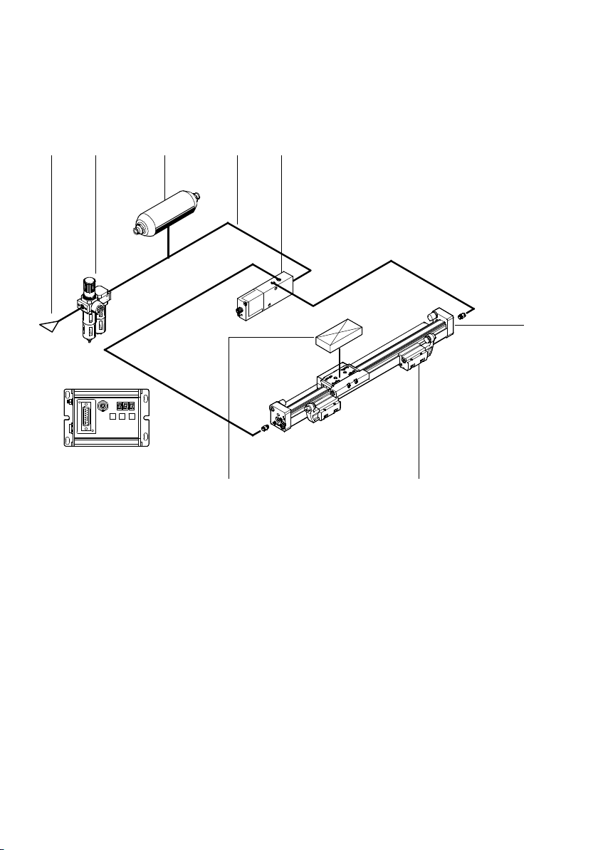
1.2 System structure with the DGCI or DDLI
The following diagram shows the basic layout of a drive with
the SPC11 using as an example drive type DGCI-... .
1
2
4
5
3
6
2
7
1
Drive (here type DGCI-... with built-on
measuring system)
2
Fixed stop (here e.g. B. KYC-...)
3
Measuring system connection
4
SPC11-MTS-AIF-2
5
Proportional directional control valve
type MPYE-5-...-010B
6
Service unit with 5 µm filter, without
lubricator
7
Compressed air source (5 to 7 bar)
Fig. 1/1: System structure of the SPC11

1. Installation instructions for the DGCI or DDLI
1-5
Festo P.BE-SPC11-DG CI-E N en 1406d
1.3 Notes on installing the pneumatic components
Caution
If the operating voltage is switched off while the com-
pressed air supply is still switched on, the actuators may
be triggered, resulting in unexpected movements which
may cause damage. Switch off the operating voltage and
the compressed air supply at the same time or in the fol-
lowing sequence:
1. the compressed air supply
2. the operating voltage
Note
Make sure that the compressed air supply and the operat-
ing voltage are switched off before starting installation and
maintenance work.
General rules for building up the system can be found in the
system manual type P.BE-SPC11-SYS... . Special instructions
on operation with linear unit type DGCI-... can be found in the
following sections:
Note
Observe the following instructions on installing the pneu-
matic components. Only then can you guarantee faultless
operation.
1. Installation instructions for the DGCI or DDLI
1-6
Festo P.BE-SPC11-DG CI-E N en 1406d
12 3 45
6
78
1
...
9
Instructions on installation see following pages
Fig. 1/2: Overview of pneumatic installation
Compressed air supply ( 1 )
See system manual type P.BE-SPC11-SYS...
Service unit ( 2 )
See system manual type P.BE-SPC11-SYS...
Compressed air reservoir ( 3 )
See system manual type P.BE-SPC11-SYS...

1. Installation instructions for the DGCI or DDLI
1-7
Festo P.BE-SPC11-DG CI-E N en 1406d
Compressed air tubing and screw connectors ( 4 )
See system manual type P.BE-SPC11-SYS...
•
Arrange the tubing between the valve (MPYE-5-...) and
the drive (DGCI/DDLI) symmetrically.
Recommendation: tubing length = drive length
•
Cut the tubing and the connectors to the required length
as shown in the following table.
Horizontal mounting position
Drive length in
mm
ValvetypeMPYE-...
Screw connectors for
Tube type
PUN
MPYE-... DGCI/DDLI-...
DGCI-18-...
100 ... 300 MPYE-5-M5-010B QSM-M5-6 QSM-M5-6 PUN-6x1
360 ... 1750 MPYE-5-1/8-LF-010B QS-1/8-6 QSM-M5-6 PUN-6x1
2000 MPYE-5-1/8-HF-010B QS-1/8-6 QSM-M5-6 PUN-6x1
DGCI/DDLI-25-...
100 ... 160 MPYE-5-1/8-LF-010B QS-1/8-6 QS-1/8-6 PUN-6x1
225 ... 300 MPYE-5-1/8-LF-010B QS-1/8-8 QS-1/8-8 PUN-8x1,25
360 ... 2000 MPYE-5-1/8-HF-010B QS-1/8-8 QS-1/8-8 PUN-8x1,25
DGCI/DDLI-32-...
100 MPYE-5-1/8-LF-010B QS-1/8-6 QS-1/8-6 PUN-6x1
160 ... 1000 MPYE-5-1/8-HF-010B QS-1/8-8 QS-1/8-8 PUN-8x1,25
1250 ... 2000 MPYE-5-1/4-010B QS-1/4-8 QS-1/8-8 PUN-8x1,25
DGCI/DDLI-40-...
100 ... 500 MPYE-5-1/8-HF-010B QS-1/8-8 QS-1/4-8 PUN-8x1,25
600 ... 750 MPYE-5-1/4-010B QS-1/4-8 QS-1/4-8 PUN-8x1,25
850 ... 2000 MPYE-5-1/4-010B QS-1/4-10 QS-1/4-10 PUN-10x1,5

1. Installation instructions for the DGCI or DDLI
1-8
Festo P.BE-SPC11-DG CI-E N en 1406d
Horizontal mounting position
Drive length in
mm
ValvetypeMPYE-...
Screw connectors for
Tube type
PUN
MPYE-... DGCI/DDLI-...
DGCI/DDLI-63-...
100 ... 300 MPYE-5-1/8-HF-010B QS-1/8-8 QS-3/8-8 PUN-8x1,25
360 ... 400 MPYE-5-1/4-010B QS-1/4-10 QS-3/8-10 PUN-10x1,5
450 ... 2000 MPYE-5-3/8-010B QS-3/8-12 QS-3/8-12 PUN-12x2
Vertical mounting position
Drive length in
mm
ValvetypeMPYE-...
Screw connectors for
Tube type
PUN
MPYE-... DGCI/DDLI-...
DGCI-18-...
100 ... 300 MPYE-5-M5-010B QSM-M5-6 QSM-M5-6 PUN-6x1
360 ... 1750 MPYE-5-1/8-LF-010B QS-1/8-6 QSM-M5-6 PUN-6x1
2000 MPYE-5-1/8-HF-010B QS-1/8-6 QSM-M5-6 PUN-6x1
DGCI/DDLI-25-...
100 ... 160 MPYE-5-1/8-LF-010B QS-1/8-6 QS-1/8-6 PUN-6x1
225 ... 750 MPYE-5-1/8-LF-010B QS-1/8-8 QS-1/8-8 PUN-8x1,25
850 ... 2000 MPYE-5-1/8-HF-010B QS-1/8-8 QS-1/8-8 PUN-8x1,25
DGCI/DDLI-32-...
100 MPYE-5-1/8-LF-010B QS-1/8-6 QS-1/8-6 PUN-6x1
160 ... 300 MPYE-5-1/8-LF-010B QS-1/8-8 QS-1/8-8 PUN-8x1,25
360 ... 1750 MPYE-5-1/8-HF-010B QS-1/8-8 QS-1/8-8 PUN-8x1,25
2000 MPYE-5-1/4-010B QS-1/4-8 QS-1/8-8 PUN-8x1,25

1. Installation instructions for the DGCI or DDLI
1-9
Festo P.BE-SPC11-DG CI-E N en 1406d
Vertical mounting position
Drive length in
mm
ValvetypeMPYE-...
Screw connectors for
Tube type
PUN
MPYE-... DGCI/DDLI-...
DGCI/DDLI-40-...
100 ... 225 MPYE-5-1/8-LF-010B QS-1/8-8 QS-1/4-8 PUN-8x1,25
300 ... 750 MPYE-5-1/8-HF-010B QS-1/8-8 QS-1/4-8 PUN-8x1,25
850 ... 1000 MPYE-5-1/8-HF-010B QS-1/8-10 QS-1/4-10 PUN-10x1,5
1250 ... 2000 MPYE-5-1/4-010B QS-1/4-10 QS-1/4-10 PUN-10x1,5
DGCI/DDLI-63-...
100 … 225 MPYE-5-1/8-LF-010B QS-1/8-8 QS-3/8-8 PUN-8x1,25
300 MPYE-5-1/8-HF-010B QS-1/8-8 QS-3/8-8 PUN-8x1,25
360 ... 450 MPYE-5-1/4-010B QS-1/4-10 QS-3/8-10 PUN-10x1,5
500 ... 2000 MPYE-5-3/8-010B QS-3/8-12 QS-3/8-12 PUN-12x2

1. Installation instructions for the DGCI or DDLI
1-10
Festo P.BE-SPC11-DG CI-E N en 1406d
Proportional directional control valve ( 5 )
See system manual type P.BE-SPC11-SYS...
The DGCI-... is suitable both for slide and yoke mode.
Work port 2 of the proportional directional control valve
must be connected to the drive conection which is on the
side with the electrical connection for the potentiometer.
1
1
Electrical connection
Fig. 1/3: Tubing connection for slide mode
1
1
Electrical connection
Fig. 1/4: Tubing connection for yoke mode

1. Installation instructions for the DGCI or DDLI
1-11
Festo P.BE-SPC11-DG CI-E N en 1406d
If the DGCI or DDLI is ordered with screw connectors – Stand-
ard (no modular system feature) or modular system feature
“QD” or “QR”:
•
Work port 2 of the proportional directional control valve
must be connected to the drive connection of the screw
connector with blue releasing ring.
•
Work port 4 of the proportional directional control valve
must be connected to the drive connection of the screw
connector with black releasing ring.
Linear drive type DGCI/DDLI ( 6 )
With the DGCI or DDLI, use only:
– drivesoftypeDGCIorDDLI.
– Permitted combinations of drives and valves, drive diam-
eter, drive lengths and mass loads, see “Parameters for
the DGCI or DDLI” in chapter 2.
– Drives with air supply on both sides (for good positioning
behaviour).
•
Fit the drive horizontally or vertically.
•
Connect the drive, the guide, the potentiometer and the
load free of play in the direction of movement and flush
with each other .
•
If necessary, provide a sufficiently large supply of energy
in order to minimize the effects of transverse forces on
the positioning behaviour.
•
Lubricate the guide of the drive at maintenance intervals
as specified in the operating instructions for the drive
(see operating instructions for the drive or the guide).

1. Installation instructions for the DGCI or DDLI
1-12
Festo P.BE-SPC11-DG CI-E N en 1406d
Fixed stops ( 7 )
With drives of type DGCI-... you can use as a fixed stop either
the integrated original stops, the shock absorber support
(without the shock absorber) type DADP-DGC-... together with
stops type KYC-... or suitable external stops.
The use of shock absorbers is not permitted.
1
2
2
3
1
1
Integrated original stops (drive end length)
2
Stop type KYC-...
3
Shock absorber support type DADP-DGC
Fig. 1/5: Fixed stops (Example DGCI)
With drives of type DDLI external fixed stops on the mounting
slide are required.
Mass load ( 8 )
Fit the mass load free of play. Use the compensating coupling
DARD from Festo.
Possible moving mass loads see “Parameters for the DGCI-...”
in chapter 2. The tables listed there contain all the permitted
combinations of drive, valve and mass load.

1. Installation instructions for the DGCI or DDLI
1-13
Festo P.BE-SPC11-DG CI-E N en 1406d
1.4 Instructions on converting systems
When converting systems you should use further the existing
drives. Only drives with air supply on one side are often avail-
able here.
The specified positioning times as well as optimum system
behaviour can only be achieved if the installation instructions
described in the previous section are observed.
Drives with compressed air supply on one side
Please observe the following when using drives compressed
air supply on one side:
– When compressed air is applied to port 4 of the propor-
tional directional control valve, the slide must move in
the direction of the measuring system zero point (electri-
cal connection of the measuring system).
If compressed air is applied to port 2, the slide must move
away from the measuring system zero point.
– The resulting positioning times may vary according to the
direction of the stroke.
1
1
Electrical connection (measuring system zero point)
Fig. 1/6: Tubing on the side with the measuring system zero
point.

1. Installation instructions for the DGCI or DDLI
1-14
Festo P.BE-SPC11-DG CI-E N en 1406d
If the DGCI or DDLI is ordered with screw connectors – modu-
lar design feature “QR:”
•
Work port 2 of the proportional directional control valve
must be connected to the drive connection of the screw
connector with blue releasing ring.
•
Work port 4 of the proportional directional control valve
must be connected to the drive connection of the screw
connector with black releasing ring.
1.5 Notes on installing the electronic components
Caution
Incorrect or missing earthing can cause interference.
Connect the DGCI-... drive with low impedance (short
cable with large cross-sectional area) to the earth poten-
tial, if the drive is not mounted on an earthed machine
stand.

Parameters of the SPC11 for the DGCI or DDLI
2-1
Festo P.BE-SPC11-DG CI-E N en 1406d
Chapter 2
Parameters of the SPC11 for the DGCI or DDLI

2. Parameters of the SPC11 for the DGCI or DDLI
2-2
Festo P.BE-SPC11-DG CI-E N en 1406d
Contents
2.1 SPC11 parameters 2-3..............................................
2.2 Setting parameters 2-5..............................................
2.3 Parameters for the DGCI/DDLI in horizontal mode 2-8.....................
2.3.1 DGCI-18-... in horizontal mode 2-8.............................
2.3.2 DGCI/DDLI-25-... in horizontal mode 2-13........................
2.3.3 DGCI/DDLI-32-... in horizontal mode 2-18........................
2.3.4 DGCI/DDLI-40-... in horizontal mode 2-23........................
2.3.5 DGCI/DDLI-63-... in horizontal mode 2-28........................
2.4 Parameters for the DGCI/DDLI in vertical mode 2-33.......................
2.4.1 DGCI-18-... in vertical mode 2-33...............................
2.4.2 DGCI/DDLI-25-... in vertical mode 2-38..........................
2.4.3 DGCI/DDLI-32-... in vertical mode 2-43..........................
2.4.4 DGCI/DDLI-40-... in vertical mode 2-48..........................
2.4.5 DGCI/DDLI-63-... in vertical mode 2-53..........................
Loading...