

Page 1

www.ferm.com
Art.No. MMM1007
MMH-600
GB
D
NL
F
E
P
I
S
FIN
N
DK
H
CZ
SLO
PL
USERS MANUAL 03
BEDIENUNGSANLEITUNG 07
GEBRUIKSAANWIJZING 12
MODE D’EMPLOI 17
MANUAL DE INSTRUCCIONES 22
ISTRUÇÕN A USAR 27
MANUALE UTILIZZATI 31
BRUKSANVISNING 36
KÄYTTÖOHJE 40
BRUKSANVISNING 45
BRUGERVEJLEDNING 49
HASZNÁLATI UTASÍTÁS 54
NÁVOD K POUŽITÍ 58
NOVODILA ZA UPORABO 63
INSTRUKSJĘ OBSŁUGI 67
РУКОВОДСТВО ПО ЭКСПЛУАТАЦИИ 72
O¢∏°π∂™ Ã∏™∂ø™ 77
RUS
GR
www.ferm.com 0610-31
GB Subject to change
D Änderungen vorbehalten
NL Wijzigingen voorbehouden
F Sous réserve de modifications
E Reservado el derecho de
modificaciones técnicas
P Reservado o direito a modificações
I Con riserva di modifiche
S Ändringar förbehålles
FIN Pidätämme oikeuden muutoksiin
N Rett till endringer forbeholdes
DK Ret til ændringer forbeholdes
H Változtatás jogát fenntartjuk
CZ Změny vyhrazeny
SLO Predmet sprememb
PL Temat do zmiany
RUS Компания Ferm постоянно
совершенству ет выпускаемую ею
продукцию. Поэтому в технические
характеристики могут вноситься
измнения без предварительного
уведомления.
GR HÚԇ̠ÙÔ ‰Èη›ˆÌ· ·ÏÏ·ÁÒÓ
Page 2
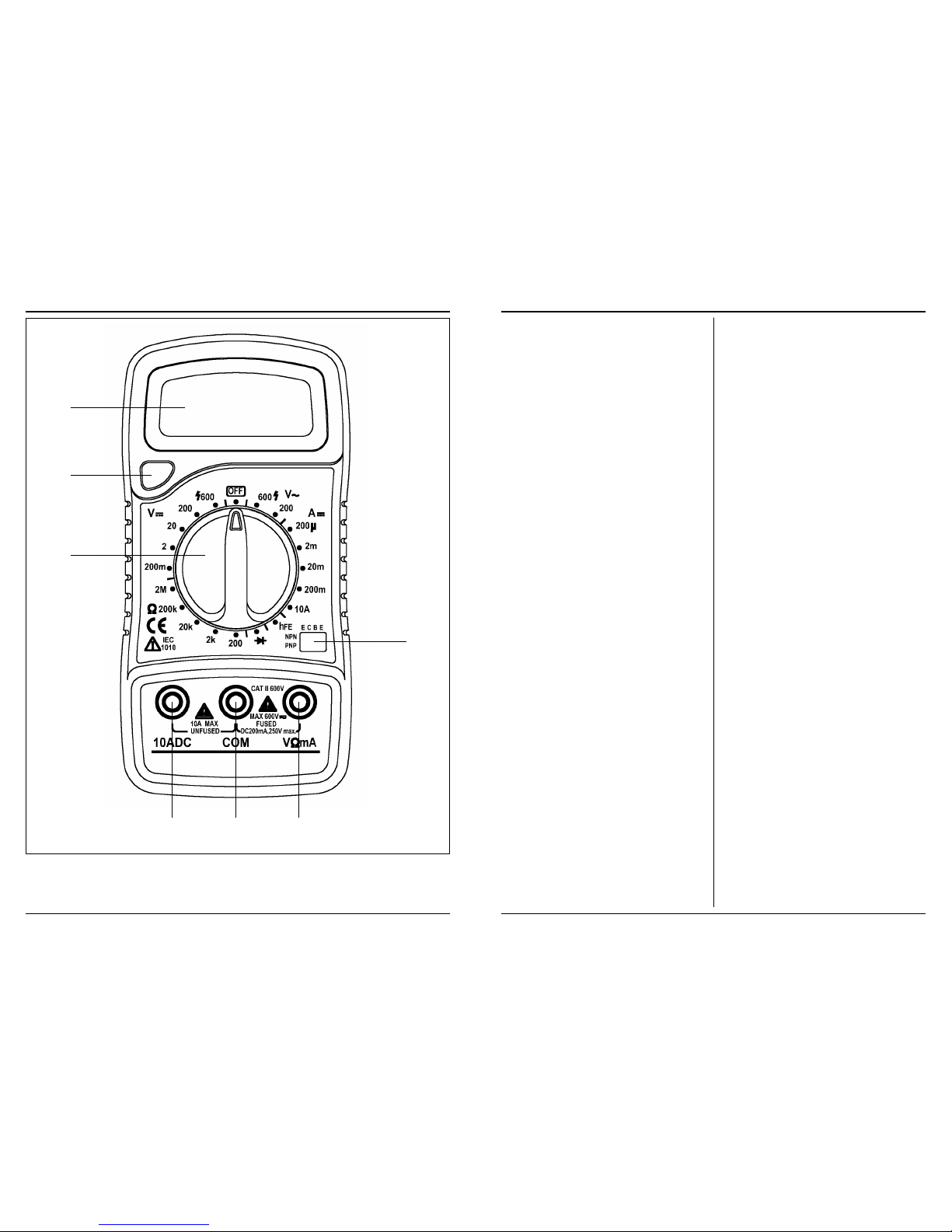
Ferm 83
Fig. 1
02 Ferm
A
G
B
DEF
C
Page 3

¢ЛПТУФ˘МВ МВ ·ФОПВИЫЩИО‹ М·˜ В˘ı‡УЛ, fiЩИ
·˘Ùfi ÙÔ
MMH-600
ÏËÚÔ› Ù· ·Ú·Î¿Ùˆ ÚfiÙ˘· ‹ Ù· ¤ÁÁÚ·Ê·
ÚÔÙ‡ˆÓ:
EN61010-1, IEC61010-031
EN55022, EN61000-4-2, EN61000-4-3
™‡Ìʈӷ Ì ÙȘ Ô‰ËÁ›Â˜:
73/23/∂EC, 89/336/∂EC
01-10-2006
ZWOLLE NL
J.A. Bakker - van Ingen
CEO Ferm BV
J. Lodewijk
Quality Manager Ferm
Global
¢В‰ФМ¤УФ˘ fiЩИ Л ‰И·ЪО‹˜ ‚ВПЩ›ˆЫЛ ЩˆУ
ЪФ˚fiУЩˆУ М·˜ ·ФЩВПВ› ФПИЩИО‹ ЩЛ˜ ВЩ·ИЪВ›·˜
М·˜, ВИК˘П·ЫЫfiМВı· ЩФ˘ ‰ИО·ИТМ·ЩФ˜ У·
ЩЪФФФИФ‡МВ ЩИ˜ ЪФ‰И·БЪ·К¤˜ ЩФ˘ ЪФ˚fiУЩФ˜
¯ˆЪ›˜ ЪФЛБФ‡МВУЛ ВИ‰ФФ›ЛЫЛ.
Ferm BV ñ Lingenstraat 6 ñ 8028 PM Zwolle
√ÏÏ·Ó‰›·
CE
ı
¢∏§ø™∏ ™Àªª√ƒºø™∏™
(GR)
82 Ferm
The following icons appear on this device:
Risk of damaging material and/or physical
injuries
In accordance with essential applicable
safety standards of European directives.
Class II machine – double insulation
Fuse 200 mA / 250 V
It points to risk of injury, life hazard and
possible damage to the device, if the
instructions in this operating manual are
not followed.
1. TECHNICAL SPECIFICATIONS
Product: Ferm Digital Multimeter
Type MMH-600 - Item. No. MMM1007
Ferm B.V, Zwolle, Netherlands
- 3,5-digit LCD display (max. display: 1999);
- Operating temperature: 0.....40 °C (relative
humidity <75 %);
- Display frequency: 2-3 /seconds
- Maximum "In-phase voltage": 600V DC.
- Storage temperature: -10.....+50 °C
The multimeter is operated with a 9V battery of the
6F22 type or alternatively: 6R61 / 6LR61 6LF22. If
the battery is flat, the display shows " ".
Calibration: Tolerances are guaranteed for a period
of one year at 18 °C - 28 °C and relative humidity of
<80 %.
PLEASE READ THROUGH THESE OPERATING
INSTRUCTIONS CAREFULLY!
2. MAKE YOURSELF FAMILIAR WITH
THE PRODUCT
Please read the operating instructions carefully
before putting the multimeter into service and in
particular, observe the safety stipulations. Service
the multimeter conforming to the instructions, so
that it will run smoothly. Use the multimeter only
when you are familiar with the operation of the
device. Preserve these operating instructions and
other records pertaining to the device carefully.
3. GENERAL SAFETY RULES
Great attention has been paid to the safety aspect in
designing this device.
Any change or extension in the device can
compromise the safety. This would even render the
warranty void and ineffective.
• Ensure order at the workplace.
- A disorderly workplace can cause accidents.
- Ensure sufficient illumination at the
workplace.
• Pay attention to the environmental factors.
• Do not use the multimeter in humid or wet
surroundings. Protect the multimeter from rain
and humidity.
• Keep children away from it.
• Keep other persons away from the work area
and ensure that they do not touch the
multimeter.
• Store the device in a safe place. Multimeters,
which are not used for a while, must be stored in
a dry room.
• Do not overload the multimeter. Work within the
indicated working range: this is better and safer.
Damages caused by overloading do not fall
within the purview of the guarantee.
• Do not use the instrument leads improperly. Do
not carry the device suspended by the
instrument leads and do not pull the plug from
the multimeter by the instrument leads; always
pull on the plug itself.
• Service the multimeter with care.
• Keep the multimeter clean. This facilitates work
and augments the safety. See that the
multimeter does not come in contact with
humidity, oil or fat.
• Pull the plugs out of the instrument leads from
the multimeter, when the multimeter is not in
use.
• Check if the device is damaged.
• Before using the device, recheck whether the
device and instrument leads are in proper
condition and function correctly.
4. SPECIAL SAFETY RULES
1. WARNING!Measuring high voltages and
currents poses a life hazard. Never touch
exposed metallic parts of the instrument leads.
2. The multimeter is sensitive. Protect it from
vibrations and do not let it fall down.
3. If the multimeter is not going to be used for a
time, please switch it OFF to save on batteries.
4. If the multimeter is not gong to be used for a long
period, remove the battery in order to avoid
spilling.
5. Do not subject the device to high humidity or high
temperatures.
6. Keep the multimeter away from strong magnetic
fields.
7. Remove the instrument leads immediately if you
smell burnt cable insulation.
8. Use the multimeter only if the housing is closed.
9. Use the multimeter only for measurements of
the class I or II.
Do not use the multimeter for measurements in
the class III or IV.
- +
Ferm 03
Page 4

3. ∞У Л ·УЩ›ЫЩ·ЫЛ Ф˘ ЪfiОВИЩ·И У· МВЩЪЛıВ› В›У·И
Ы˘У‰В‰ВМ¤УЛ ЫВ О‡ОПˆМ·, ı· Ъ¤ВИ У·
‰И·Оfi„ВЩВ ЩЛУ Щ¿ЫЛ О·И У· КЪФУЩ›ЫВЩВ ТЫЩВ У·
ВОКФЪЩˆıФ‡У fiПФИ ФИ ˘ОУˆЩ¤˜ ЪИУ ·Ъ¯›ЫВЩВ
ЩЛ М¤ЩЪЛЫЛ.
10.5 ª¤ЩЪЛЫЛ ‰Иfi‰ˆУ (Щ¿ЫЛ О·Щ¿ЫЩ·ЫЛ˜
·ÁˆÁ‹˜)
1. ™˘У‰¤ЫЩВ ЩФ ª∞Аƒ√ О·ПТ‰ИФ ЫЩЛУ ˘Ф‰Ф¯‹
“COM” О·И ЩФ ∫√∫∫π¡√ О·ПТ‰ИФ ЫЩЛУ
˘Ф‰Ф¯‹ “V mA”. (Аfi‰ВИНЛ: ∏ ФПИОfiЩЛЩ· ЩФ˘
ОfiООИУФ˘ О·Пˆ‰›Ф˘ В›У·И “+”.)
2. ƒ˘ıÌ›ÛÙ ÙÔÓ ‰È·ÎfiÙË FUNCTION ÛÙËÓ
ÂÚÈÔ¯‹ О·И Ы˘У‰¤ЫЩВ ЩИ˜ ·О›‰В˜ М¤ЩЪЛЫЛ˜
ЫЩЛ ‰›Ф‰Ф Ф˘ ı¤ПВЩВ У· МВЩЪ‹ЫВЩВ. ∫·Щ¿ ЩЛ
М¤ЩЪЛЫЛ ‰Иfi‰ˆУ ‹ ЩЪ·У˙›ЫЩФЪ, Л ФПИОfiЩЛЩ·
ЩˆУ ·О›‰ˆУ М¤ЩЪЛЫЛ˜ О·ıФЪ›˙ВИ ·У МВЩЪИ¤Щ·И Л
ВМЪfiЫıИ· О·ЩВ‡ı˘УЫЛ ‹ Л О·ЩВ‡ı˘УЫЛ
·ФОПВИЫМФ‡. ∏ ЩИМ‹ Ф˘ К·›УВЩ·И ЫЩЛУ ФıfiУЛ
В›У·И Л ЩТЫЛ Щ¿ЫЛ˜ ЫЩЛУ О·Щ¿ЫЩ·ЫЛ ·БˆБ‹˜.
- ∏ ÈÛ¯‡˜ ·ÂÌÏÔ΋˜ Â›Ó·È 0.8 mA.
- ∞У ФИ ·О›‰В˜ М¤ЩЪЛЫЛ˜ ‰ВУ В›У·И Ы˘У‰В‰ВМ¤УВ˜
(ЫˆЫЩ¿) ЫЩЛ ‰›Ф‰Ф, .¯. ЪФ˜ ЩЛУ О·ЩВ‡ı˘УЫЛ
·ФОПВИЫМФ‡, Л ФıfiУЛ ı· ‰В›¯УВИ ЩФУ ·ЪИıМfi 1.
10.6 ª¤ЩЪЛЫЛ ЩЪ·У˙›ЫЩФЪ hFE
1. ∞К·ИЪ¤ЫЩВ ЩФ О·ПТ‰ИФ М¤ЩЪЛЫЛ˜.
2. µ¿ÏÙ ÙÔÓ ‰È·ÎfiÙË ÛÙË Ú‡ıÌÈÛË hFE.
3. ∂П¤БНЩВ ·У ЩФ Ы˘БОВОЪИМ¤УФ ЩЪ·У˙›ЫЩФЪ В›У·И
Щ‡Ф˘ NPN ‹ PNP О·И Ы˘У‰¤ЫЩВ ЩФ О·ПТ‰ИФ
ЩФ˘ ВОФМФ‡ (e), ЩЛ˜ ‚¿ЫЛ˜ (b) О·И ЩФ˘
Ы˘ПП¤ОЩЛ (c ) ЫЩЛУ О·Щ¿ППЛПЛ ˘Ф‰Ф¯‹ ЫЩФУ
›У·О· Ф˘ ‚Ъ›ЫОВЩ·И ЫЩФ ВМЪfi˜ М¤ЪФ˜.
4. ∏ ФıfiУЛ ‰В›¯УВИ (О·Щ¿ ЪФЫ¤ББИЫЛ) ЩЛУ ЩИМ‹
hFE БИ· ¤У· ‚·ЫИОfi ЪВ‡М· 10 mA, V CE 2.8 V.
11. ™À¡∆∏ƒ∏™∏
¶ƒ√™√Ã∏
с £· Ъ¤ВИ ¿УЩФЩВ У· ‚Б¿˙ВЩВ ЩЛУ М·Щ·Ъ›·
ЪИУ ·fi ЩЛ Ы˘УЩ‹ЪЛЫЛ О·И ЩФУ О·ı·ЪИЫМfi ЩФ˘
ФП˘М¤ЩЪФ˘. ªЛ ¯ЪЛЫИМФФИВ›ЩВ ФЩ¤ УВЪfi ‹
¿ПП· ˘БЪ¿ БИ· ЩФУ О·ı·ЪИЫМfi ЩЛ˜ Ы˘ЫОВ˘‹˜.
с ¢И·ЩЛЪВ›ЩВ Щ· О·ПТ‰И· М¤ЩЪЛЫЛ˜ О·И ЩФ
ФП‡МВЩЪФ О·ı·Ъ¿. √ЪИЫМ¤У· М¤Ы·
О·ı·ЪИЫМФ‡ ‹ ‰И·П‡ЩВ˜ (ВЩЪ¤П·ИФ, ·Ъ·ИˆЩИО¿
О.П.) МФЪВ› У· ЪФЫ‚¿ПФ˘У ‹ У· ‰И·П‡ЫФ˘У
Щ· П·ЫЩИО¿ М¤ЪЛ. ∞˘Щ¿ Щ· ЪФ˚fiУЩ·
ВЪИ¤¯Ф˘У ‚ВУ˙fiПИФ, ЩЪИ¯ПˆЪФ·Иı¿УИФ,
¯ПТЪИФ, ˘БЪ‹ ·ММˆУ›· О.П.
ñ ∫·ı·Ú›˙ÂÙ ٷÎÙÈο ÙÔ ÂÚ›‚ÏËÌ· Ì ¤Ó·
Ì·Ï·Îfi ·Ó›, ηٿ ÚÔÙ›ÌËÛË ÌÂÙ¿ ·fi οıÂ
¯Ú‹ÛË.
ñ ∞Ê·ÈÚ¤ÛÙ ÙȘ ›ÌÔÓ˜ ‚ÚÔÌȤ˜ Ì ¤Ó· ˘ÁÚfi
·У›. ªЛ ¯ЪЛЫИМФФИВ›ЩВ ‰И·П‡ЩВ˜ fiˆ˜
ВЩЪ¤П·ИФ, ФИУfiУВ˘М·, ‰И¿П˘М· ·ММˆУ›·˜
О.П. ∞˘Щ¿ Щ· ˘БЪ¿ ЪФО·ПФ‡У ˙ЛМИ¿ ЫЩ·
П·ЫЩИО¿ М¤ЪЛ ЩЛ˜ Ы˘ЫОВ˘‹˜.
12. ¶ƒ√µ§∏ª∞∆∞
∞У ЩФ ФП‡МВЩЪФ ‰ВУ ПВИЩФ˘ЪБВ› ЫˆЫЩ¿, ФИ ·ИЩ›В˜
МФЪВ› У· В›У·И ФИ ВН‹˜:
1. ∆Ф ФП‡МВЩЪФ ‰ВУ ‰В›¯УВИ Щ›ФЩ· ЫЩЛУ ФıfiУЛ.
ñ ∏ Ì·Ù·Ú›· Â›Ó·È ¿‰ÂÈ·.
- ∞ÓÙÈηٷÛÙ‹ÛÙ ÙËÓ Ì·Ù·Ú›·.
ñ ∆Ô Ú‡̷ ‹ Ë Ù¿ÛË Ô˘ ÌÂÙÚ‹ıËΠ‹Ù·Ó
˘ВЪ‚ФПИО¿ ˘„ЛП‹, МВ ·ФЩ¤ПВЫМ· ЩФ
ФП‡МВЩЪФ У· ˘ФЫЩВ› ‚П¿‚Л, ·Ъ¿ ЩИ˜
‰И·Щ¿НВИ˜ ·ЫК·ПВ›·˜.
- ™В ВЪ›ЩˆЫЛ ЪФ‚П‹М·ЩФ˜,
ВИОФИУˆУ‹ЫЩВ МВ ЩФ ЩФИОfi О¤УЩЪФ
ЩВ¯УИО‹˜ ˘ФЫЩ‹ЪИНЛ˜.
2. ∆Ф ФП‡МВЩЪФ ‰ВУ ‰В›¯УВИ О·М›· МВЩЪФ‡МВУЛ
ЩИМ‹.
ñ Œ¯ÂÈ Î·Â› Ë ·ÛÊ¿ÏÂÈ·.
- ∞ÓÙÈηٷÛÙ‹ÛÙ ÙËÓ ·ÛÊ¿ÏÂÈ·.
с ŒУ· ‹ ВЪИЫЫfiЩВЪ· ·fi Щ· О·ПТ‰И· В›У·И
ÂÏ·Ùو̷ÙÈο.
- ∞УЩИО·Щ·ЫЩ‹ЫЩВ Щ· О·ПТ‰И· М¤ЩЪЛЫЛ˜.
ñ ∆Ô Ú‡̷ ‹ Ë Ù¿ÛË Ô˘ ÌÂÙÚ‹ıËΠ‹Ù·Ó
˘ВЪ‚ФПИО¿ ˘„ЛП‹, МВ ·ФЩ¤ПВЫМ· ЩФ
ФП‡МВЩЪФ У· ˘ФЫЩВ› ‚П¿‚Л, ·Ъ¿ ЩИ˜
‰И·Щ¿НВИ˜ ·ЫК·ПВ›·˜.
- ™В ВЪ›ЩˆЫЛ ЪФ‚П‹М·ЩФ˜,
ВИОФИУˆУ‹ЫЩВ МВ ЩФ ЩФИОfi О¤УЩЪФ
ЩВ¯УИО‹˜ ˘ФЫЩ‹ЪИНЛ˜.
∞¡∆π∫∞∆∞™∆∞™∏ ∆∏™ ∞™º∞§∂π∞™
1. µ¿ÏÙ ÙÔÓ ‰È·ÎfiÙË ÛÙË Ú‡ıÌÈÛË OFF.
2. ∞К·ИЪ¤ЫЩВ ЩФ ›Ыˆ О¿П˘ММ· ЩФ˘ ФП˘М¤ЩЪФ˘
НВ‚И‰ТУФУЩ·˜ ЩИ˜ ‚›‰В˜.
¶ƒ√™√Г∏! ∏ Ы˘ЫОВ˘‹ ı· Ъ¤ВИ У·
ЩВıВ› ВОЩfi˜ ПВИЩФ˘ЪБ›·˜ О·И Щ· О·ПТ‰И·
ı· Ъ¤ВИ У· ·К·ИЪВıФ‡У ЪИУ ·УФ›НВЩВ
ЩФ ВЪ›‚ПЛМ· ЩФ˘ ФП˘М¤ЩЪФ˘.
3. ∞Ê·ÈÚ¤ÛÙ ÙËÓ ÂÏ·Ùو̷ÙÈ΋ ·ÛÊ¿ÏÂÈ· ηÈ
·ÓÙÈηٷÛÙ‹ÛÙ ÙËÓ Ì ÌÈ· ·ÛÊ¿ÏÂÈ· Ù˘ ›‰È·˜
ÈÛ¯‡Ô˜ Î·È Ì ÙȘ ›‰È˜ ȉÈfiÙËÙ˜ ‰È·ÎÔ‹˜ (250
V~ F200mAL).
13. §§∞°∏ ∆∏™ ª¶∞∆∞ƒπ∞™
1. ∆Ф Ы‡М‚ФПФ ЩЛ˜ М·Щ·Ъ›·˜ ı· ВМК·УИЫЩВ› ЫЩЛУ
ФıfiУЛ fiЩ·У Л М·Щ·Ъ›· В›У·И Ы¯В‰fiУ ¿‰ВИ·.
2. µ¿ПЩВ ЩФ ВЪИЫЩЪФКИОfi ОФ˘М› ЫЩЛ Ъ‡ıМИЫЛ
OFF.
3. ∞К·ИЪ¤ЫЩВ ЩФ ›Ыˆ О¿П˘ММ· ЩФ˘ ФП˘М¤ЩЪФ˘
НВ‚И‰ТУФУЩ·˜ ЩИ˜ ‚›‰В˜.
¶ƒ√™√Г∏! ∏ Ы˘ЫОВ˘‹ ı· Ъ¤ВИ У·
ЩВıВ› ВОЩfi˜ ПВИЩФ˘ЪБ›·˜ О·И Щ· О·ПТ‰И·
ı· Ъ¤ВИ У· ·К·ИЪВıФ‡У ЪИУ ·УФ›НВЩВ
ЩФ ВЪ›‚ПЛМ· ЩФ˘ ФП˘М¤ЩЪФ˘.
4. ∞ÓÙÈηٷÛÙ‹ÛÙ ÙËÓ Ì·Ù·Ú›· 9 Volt Ì ÌÈ·
ηÈÓÔ‡ÚÁÈ· Ì·Ù·Ú›· Ù‡Ô˘ 6F22, ‹,
ÂÓ·ÏÏ·ÎÙÈο: 6R61 / 6LR61 / 6LF22.
Ferm 81
5. ENVIRONMENTAL PROTECTION
Raw material recovery is better than garbage
disposal. To avoid damages in transport, the device
must be delivered in solid packing made mostly
from recyclable material such as paper, pulp and
wood. We therefore recommend that you recycle
the packing as far as possible.
The multimeter is operated on batteries.
Dispose of spent batteries as stipulated.
For instructions on replacing batteries, refer to
chapter 13 "Changing batteries".
6. AFTER SALES SERVICE
Please retain the original packing. If the device
needs to be transported again, the risk of damage
during transport is minimised if you use the original
packing. If a warranty claim is made, the device
must be sent in as securely packed as possible,
preferably in the original packing. All Ferm products
undergo exhaustive testing before they leave the
factory. Should however a defect be detected in
your device, please contact at your Service address
first.
7. BEFORE PUTTING IN SERVICE
1. In case the voltage and/or the current to be
measured is/are unknown, set the rotary knob
on the largest measuring range. If the accuracy
on the rotary knob is insufficient, set on a lower
range and so on.
2. If the device is not going to be used temporarily,
put the rotary knob in the OFF position.
3. The switching of the multimeter is different for
measuring voltage and for measuring current.
Parallel connection in voltage measurement
and series connection in current measurement.
In the latter case, a conductor in the power circuit
to be measured must be interrupted.
4. Never connect a power source or voltage to the
multimeter, if the FUNCTION switch is in the or
position.
5. Never connect a voltage higher than 600 V DC or
600 V to the measuring device.
8. BRIEF SYNOPSIS FOR
MEASUREMENTS
The multimeter is suitable for measuring:
• Direct voltage (VDC, voltage of accumulator or
battery, for example)
• Direct current (ADC)
• Alternating voltage (VAC, voltage of the mains
input of a device, for example)
• Resistance ( , Ohm)
• Diodes and hFE transistor measurement
A measurement object can be under voltage.
To measure it, connect the multimeter in parallel.
If the current strength is to be measured, include the
multimeter in the circuit (series connection). The
power circuit for measuring the current must
necessarily be isolated, because the current has to
flow through the multimeter.
You must not switch the multimeter on Current
measurement, for example, if you are measuring
the voltage. You could damage the multimeter
beyond repair by causing a short circuit in this case.
9. OPERATION (REFER TO FIGURE 1).
A. 3,5-digit LCD display (max. display: 1999.
Display of decimal point, polarity, overload and
discharged battery indication.
B. FUNCTION switch: Rotary switch for the range
to be set
C. hFE-transistor measuring
D. 10 A. Positive connection for current
measurements over 200 mA up to a maximum
value of 10 A.
E. COM. Negative connection.
F. V mA. Positive connection for voltage and
resistance measurements. Up to 200 mA.
G. Hold button
When this button is pushed, the display will keep
the last reading and "H" symbol will appear on
the LCD until pushing it again.
10. MEASUREMENTS
10.1 Measuring direct voltage (V DC)
1. Connect the BLACK lead to the "COM"
connector socket and the RED lead to the
"V mA" connector socket.
2. Set the FUNCTION switch on the desired "V"
setting and connect the leads to the voltage
source to be measured or measuring points.
Observe correct polarity (red is + and black is -),
otherwise the display shows a minus sign before
the value.
3. Read off the measured value in Volt.
RANGE ACCURACY RES.
Input resistance 10 M
Overload protection DC 600 V or AC 600 V Effective
value
(outside 200-mV-range with highest value of 250 V
Effective value).
± 0,5% of rdg ± 2 digit
± 0,8% of rdg ± 2 digit
200mV
2000mV
20V
200V
600V
100µV
1mV
10mV
100mV
1V
04 Ferm
Page 5

¶∂ƒπ√Ã∏ ∞∫ƒπµ∂π∞ ∞¡∞.
∞ÓÙ›ÛÙ·ÛË ÂÈÛfi‰Ô˘ 10 M
¶ÂÚÈÔ¯‹ Û˘¯ÓfiÙËÙ·˜ 40.....400 Hz.
¶ЪФЫЩ·Ы›· ˘ВЪКfiЪЩИЫЛ˜: ВУВЪБfi˜ ЩИМ‹ AC 600 V
‹ М¤БИЫЩЛ ЩИМ‹ DC 600 V (Ы˘УВ¯Т˜ ЫВ fiПВ˜ ЩИ˜
ВЪИФ¯¤˜).
ŒÓ‰ÂÈÍË: ¢ИФЪıˆМ¤УЛ М¤ЫЛ ЩИМ‹ ·УЩИЫЩФИ¯В› ЫЩЛУ
ВУВЪБfi ЩИМ‹ ЛМИЩФУФВИ‰Ф‡˜ Ы¯‹М·ЩФ˜.)
À¶√¢∂π•∏:
1. ∞У ‰ВУ БУˆЪ›˙ВЩВ ЩЛУ ВЪИФ¯‹ Щ¿ЫЛ˜, ı·
Ъ¤ВИ У· ‚¿ПВЩВ ЩФУ ‰И·ОfiЩЛ FUNCTION
ЫЩЛУ ·УТЩ·ЩЛ ВЪИФ¯‹ М¤ЩЪЛЫЛ˜ О·И У·
МВИТЫВЩВ ЫЩ·‰И·О¿ ЩЛУ ВЪИФ¯‹, ·У ¯ЪВИ·ЫЩВ›.
2. ∞У ВМК·УИЫЩВ› Л ¤У‰ВИНЛ “1” ЫЩЛУ ФıfiУЛ, Л
МВЩЪФ‡МВУЛ ЩИМ‹ ‚Ъ›ЫОВЩ·И ВОЩfi˜ ЩЛ˜
Ъ˘ıМИЫМ¤УЛ˜ ВЪИФ¯‹˜. √ ‰И·ОfiЩЛ˜
FUNCTION ı· Ъ¤ВИ У· Ъ˘ıМИЫЩВ› ЫВ
˘„ЛПfiЩВЪЛ ВЪИФ¯‹.
3. ∏ М¤БИЫЩЛ Щ¿ЫЛ ВИЫfi‰Ф˘ В›У·И 600 V DC,
ВУВЪБfi˜ ЩИМ‹. ∏ М¤ЩЪЛЫЛ ˘„ЛПfiЩВЪˆУ Щ¿ЫВˆУ
‰ВУ В›У·И ‰˘У·Щ‹.
4. ¶ÚÔÛ¤¯ÂÙ ¿Ú· Ôχ fiÙ·Ó ÌÂÙÚ¿Ù ˘„ËϤ˜
Ù¿ÛÂȘ.
10.3 ª¤ЩЪЛЫЛ Ы˘УВ¯Ф‡˜ ЪВ‡М·ЩФ˜ (ADC)
1. ™˘Ó‰¤ÛÙ ÙÔ ª∞Àƒ√ ηÏÒ‰ÈÔ ÛÙËÓ ˘Ô‰Ô¯‹
COM. ™˘Ó‰¤ÛÙ ÙÔ ∫√∫∫π¡√ ηÏÒ‰ÈÔ ÛÙËÓ
˘Ô‰Ô¯‹ “V mA”.°È· ÌÂÁ¤ıË ÌÂٷ͇ 200mA ηÈ
10A, ·Ê·ÈÚ¤Û·ÙÂ ÙËÓ ∫√∫∫π¡∏ ÎÂÊ·Ï‹ ÛÙËÓ
«10A» Ú›˙· ·ÚÔ¯‹˜.
2. µ¿ПЩВ ЩФУ ‰И·ОfiЩЛ FUNCTION ЫЩЛУ
ВИı˘МЛЩ‹ Ъ‡ıМИЫЛ “A” О·И Ы˘У‰¤ЫЩВ Щ·
О·ПТ‰И· ЫВ ЫВИЪ¿ МВ ЩФ О‡ОПˆМ· Ф˘ ı¤ПВЩВ У·
МВЩЪ‹ЫВЩВ. ¶ЪФЫ¤НЩВ ЩЛ ЫˆЫЩ‹ ФПИОfiЩЛЩ·
(ОfiООИУФ В›У·И + О·И М·‡ЪФ В›У·И -), ‰И·КФЪВЩИО¿
Л ФıfiУЛ ı· ‰В›¯УВИ ЩФ Ы‡М‚ФПФ ПЛУ (-) ЪИУ
·fi ÙËÓ ÙÈÌ‹. ∏ Ù¯ÓÈ΋ ηÙ‡ı˘ÓÛË Ú‡̷ÙÔ˜
ÙÔ˘ ∫√∫∫π¡√À ηψ‰›Ô˘ ÚÔ˜ ÙÔ ª∞Àƒ√
ηÏÒ‰ÈÔ ÂÌÊ·Ó›˙ÂÙ·È Ù·˘Ùfi¯ÚÔÓ· Ì ÙËÓ ÈÛ¯‡
ÙÔ˘ Ú‡̷ÙÔ˜.
3. ¢È·‚¿ÛÙ ÙËÓ ÙÈÌ‹ Û (milli-) Ampere.
¶∂ƒπ√Ã∏ ∞∫ƒπµ∂π∞ ∞¡∞.
∞ЫК¿ПВИ· ˘ВЪКfiЪЩИЫЛ˜: ·ЫК¿ПВИ· 0.2 A/250-V, Л
ВЪИФ¯‹ 10 A ‰ВУ ЪФЫЩ·ЩВ‡ВЩ·И.
À¶√¢∂π•∏:
1. ∞У ‰ВУ БУˆЪ›˙ВЩВ ЩЛУ ВЪИФ¯‹ ЪВ‡М·ЩФ˜, ı·
Ъ¤ВИ У· ‚¿ПВЩВ ЩФУ ‰И·ОfiЩЛ FUNCTION
ЫЩЛУ ·УТЩ·ЩЛ ВЪИФ¯‹ М¤ЩЪЛЫЛ˜ О·И У·
МВИТЫВЩВ ЫЩ·‰И·О¿ ЩЛУ ВЪИФ¯‹ М¤ЩЪЛЫЛ˜, ·У
¯ЪВИ·ЫЩВ›.
2. ∞У ВМК·УИЫЩВ› Л ¤У‰ВИНЛ “1” ЫЩЛУ ФıfiУЛ, Л
МВЩЪФ‡МВУЛ ЩИМ‹ ‚Ъ›ЫОВЩ·И ВОЩfi˜ ЩЛ˜
Ъ˘ıМИЫМ¤УЛ˜ ВЪИФ¯‹˜ М¤ЩЪЛЫЛ˜. √
‰И·ОfiЩЛ˜ FUNCTION ı· Ъ¤ВИ У· Ъ˘ıМИЫЩВ›
ЫВ ˘„ЛПfiЩВЪЛ ВЪИФ¯‹ М¤ЩЪЛЫЛ˜.
3. ∏ ÂÚÈÔ¯‹ 10A ‰ÂÓ ÚÔÛٷهÂÙ·È ÌÂ
·ЫК¿ПВИ·. °И· ЩФУ ПfiБФ ·˘Щfi, МЛУ
Ъ·БМ·ЩФФИВ›ЩВ М¤ЩЪЛЫЛ БИ· ВЪИЫЫfiЩВЪ·
·fi 10 ‰Â˘ÙÂÚfiÏÂÙ·.
10.4 ª¤ЩЪЛЫЛ ЩЛ˜ ·УЩ›ЫЩ·ЫЛ˜ ( Ohm)
1. ™˘У‰¤ЫЩВ ЩФ ª∞Аƒ√ О·ПТ‰ИФ ЫЩЛУ ˘Ф‰Ф¯‹
“COM” О·И ЩФ ∫√∫∫π¡√ О·ПТ‰ИФ ЫЩЛУ
˘Ф‰Ф¯‹ “V mA”. (Аfi‰ВИНЛ: ∏ ФПИОfiЩЛЩ· ЩФ˘
ОfiООИУФ˘ О·Пˆ‰›Ф˘ В›У·И “+”.)
2. ƒ˘ıМ›ЫЩВ ЩФУ ‰И·ОfiЩЛ FUNCTION ЫЩЛУ
ВИı˘МЛЩ‹ ВЪИФ¯‹ М¤ЩЪЛЫЛ˜ “ ”.
¶∂ƒπ√Ã∏ ∞∫ƒπµ∂π∞ ∞¡∞.
∞ЫК¿ПВИ· ˘ВЪКfiЪЩИЫЛ˜: ВУВЪБfi˜ ЩИМ‹ 250 V DC
‹ AC, БИ· ЩФ ФП‡ 15 ‰В˘ЩВЪfiПВЩ·
3. ™˘У‰¤ЫЩВ ЩИ˜ ·О›‰В˜ М¤ЩЪЛЫЛ˜ ЫЩФ ЫЩФИ¯В›Ф
Ф˘ ı¤ПВЩВ У· МВЩЪ‹ЫВЩВ. µВ‚·ИˆıВ›ЩВ fiЩИ ЩФ
ЫЩФИ¯В›Ф ‰ВУ В›У·И Ы˘У‰В‰ВМ¤УФ МВ Щ· ¿ПП·
ЫЩФИ¯В›·. ªЛУ ·ББ›˙ВЩВ ЩИ˜ ·О›‰В˜ М¤ЩЪЛЫЛ˜ БИ·
У· МЛУ ВЛЪВ¿ЫВЩВ ЩИ˜ ЩИМ¤˜ ЩЛ˜ ·УЩ›ЫЩ·ЫЛ˜.
4. ¢И·‚¿ЫЩВ ЩЛ МВЩЪФ‡МВУЛ ЩИМ‹ ЫВ (Ohm).
5. ∫·Щ¿ ЩЛ М¤ЩЪЛЫЛ ·УЩИЫЩ¿ЫВˆУ О·Щ·У·ПТУВЩ·И
ЪВ‡М· ·fi ЩЛУ ВЫˆЩВЪИО‹ М·Щ·Ъ›·. ∏
О·Щ·У¿ПˆЫЛ ЪВ‡М·ЩФ˜ ı· ФИО›ППВИ ·У¿ПФБ·
МВ ЩЛУ ВИПВБМ¤УЛ ВЪИФ¯‹ МВЩЪ‹ЫВˆУ.
À¶√¢∂π•∏:
1. ∞У Л МВЩЪФ‡МВУЛ ЩИМ‹ НВВЪУ¿ ЩЛУ ·УТЩ·ЩЛ
ЩИМ‹ ЩЛ˜ ВИПВБМ¤УЛ˜ ВЪИФ¯‹˜ МВЩЪ‹ЫВˆУ, Л
ФıfiУЛ ı· ‰В›НВИ “1”. ∂ИП¤НЩВ МИ· ˘„ЛПfiЩВЪЛ
ВЪИФ¯‹ МВЩЪ‹ЫВˆУ. ∞У Л ·УЩ›ЫЩ·ЫЛ В›У·И
ВЪ›Ф˘ 1 ª ‹ ˘„ЛПfiЩВЪЛ, Л Ы˘ЫОВ˘‹
М¤ЩЪЛЫЛ˜ ВУ‰¤¯ВЩ·И У· ¯ЪВИ·ЫЩВ› П›Б·
‰В˘ЩВЪfiПВЩ· БИ· У· ЫЩ·ıВЪФФИЛıВ›. ∞˘Щfi
В›У·И К˘ЫИФПФБИОfi fiЩ·У МВЩЪФ‡УЩ·И ˘„ЛП¤˜
·УЩИЫЩ¿ЫВИ˜.
2. ∞У Л В›ЫФ‰Ф˜ ‰ВУ В›У·И Ы˘У‰В‰ВМ¤УЛ, .¯. ЫВ
‰И·ОВОФММ¤УФ О‡ОПˆМ·, Л ФıfiУЛ ı· ‰В›¯УВИ ЩФУ
·ЪИıМfi “1”. ∞˘Щfi ЫЛМ·›УВИ fiЩИ Л М¤ЩЪЛЫЛ
‚Ъ›ЫОВЩ·И ВОЩfi˜ ЩЛ˜ ВИПВ¯ıВ›Ы·˜ ВЪИФ¯‹˜.
200
2000
20K
200K
2000K
0,1
1
10
100
1k ± 1% of rdg ± 2 digit
± 0,8% of rdg ± 2 digit
± 0,8% of rdg ± 3 digit
± 1% of rdg ± 2 digit
± 1,5% of rdg ± 2 digit
200µA
2000µA
20mA
200mA
0,1µA
1µA
10µA
100µA
± 3% of rdg ± 2 digit10A 10mA
± 1,2% of rdg ± 10 digit
200V
600V
100mV
1V
80 Ferm
HINT:
1. In case the voltage range is unknown, you must
put the FUNCTION switch in the highest
measurement range and then reduce the range
gradually if required.
2. If the figure "1" now appears on the display, the
measurand lies outside the range set. The
FUNCTION switch must be switched to a higher
range.
3. The maximum input voltage is 600 V DC. Higher
voltages cannot be measured.
4. Proceed extremely cautiously with the
measurement of high voltages.
10.2 Measuring alternating voltage (V AC)
1. Connect the BLACK lead to the "COM"
connecting point and the RED lead to the
"V mA" connecting point.
2. Set the FUNCTION switch on the desired "V"
setting and connect the leads to the voltage
source to be measured or measuring points. The
polarity of the measuring tips is not relevant.
3. Read off the measured value in Volt.
RANGE ACCURACY RES.
Input resistance 10 M
Frequency range 40.....400 Hz.
Overload protection AC 600 V Effective value or DC
600 V peak value (constantly in all ranges).
Display:Corrected centre point corresponds to the
effective value in a sinusoidal form.)
HINT:
1. In case the voltage range is unknown, you must
set the FUNCTION switch in the highest
measurement range and then reduce the range
gradually if required.
2. If the figure "1" now appears on the display, the
measurand lies outside the range set. The
FUNCTION switch must be switched to a higher
range.
3. The maximum input voltage is 600 V AC
effective value. Higher voltages cannot be
measured.
4. Proceed extremely cautiously with the
measurement of high voltages.
10.3 Measuring direct current (ADC)
1. Connect the BLACK lead to the COM connector
socket. Connect the RED lead to the "V mA"
connector socket. For measurements between
200mA and 10A, remove RED lead to “10A”
connector socket.
2. Set the FUNCTION switch on the desired "A"
setting and connect the leads in series to the
power circuit to be measured. Observe correct
polarity (red is + and black is -), otherwise the
display shows a minus sign before the value.
The technical current direction of the RED lead
to the BLACK lead is displayed at the same time
with the current strength.
3. Read off the value in (milli-) Ampere.
RANGE ACCURACY RES.
Overload protection 0.2 A/250-V cut-out, 10-Arange not protected.
HINT:
1. In case the current range is previously unknown,
you must set the FUNCTION switch in the
highest measurement range and then reduce
the measurement range gradually if required.
2. If the figure "1" now appears on the display, the
measurand lies outside the set measurement
range. The FUNCTION switch must be switched
to a higher measurement range.
3. The 10A range is not protected with a fuse. Do
not, therefore, measure for longer than 10
seconds.
10.4 Measuring the resistance ( Ohm)
1. Connect the BLACK lead to the "COM"
connector socket and the RED lead to the
"V mA" connector socket. (Hint: The polarity of
the red lead is then "+".)
2. Set the FUNCTION switch on the desired " "
measuring range.
RANGE ACCURACY RES.
Overload protection 250 V DC or AC Effective
value, for maximum 15 seconds
3. Connect the measuring tips to the components
to be measured. Ensure that the component is
not linked to the other components. Do not touch
the measuring tips so as not to affect resistance
values.
4. Read off the measured value in (Ohm).
200
2000
20K
200K
2000K
0,1
1
10
100
1k ± 1% of rdg ± 2 digit
± 0,8% of rdg ± 2 digit
± 0,8% of rdg ± 3 digit
± 1% of rdg ± 2 digit
± 1,5% of rdg ± 2 digit
200µA
2000µA
20mA
200mA
0,1µA
1µA
10µA
100µA
± 3% of rdg ± 2 digit10A 10mA
± 1,2% of rdg ± 10 digit
200V
600V
100mV
1V
Ferm 05
Page 6
2. ∞У ‰ВУ ЪfiОВИЩ·И У· ¯ЪЛЫИМФФИ‹ЫВЩВ
ЪФЫˆЪИУ¿ ЩЛ Ы˘ЫОВ˘‹, Ъ˘ıМ›ЫЩВ ЩФ
ВЪИЫЩЪФКИОfi ОФ˘М› ЫЩЛ ı¤ЫЛ OFF.
3. ∏ МВЩ·БˆБ‹ ЩФ˘ ФП˘М¤ЩЪФ˘ В›У·И ‰И·КФЪВЩИО‹
БИ· ЩЛ М¤ЩЪЛЫЛ Щ¿ЫЛ˜ О·И БИ· ЩЛ М¤ЩЪЛЫЛ
ЪВ‡М·ЩФ˜. ¶·Ъ¿ППЛПЛ Ы‡У‰ВЫЛ О·Щ¿ ЩЛ
М¤ЩЪЛЫЛ Щ¿ЫВˆ˜ О·И Ы‡У‰ВЫЛ ЫВ ЫВИЪ¿ О·Щ¿ ЩЛ
М¤ЩЪЛЫЛ ЪВ‡М·ЩФ˜. ™ЩЛУ ЩВПВ˘Щ·›· ВЪ›ЩˆЫЛ
ı· Ъ¤ВИ У· ‰И·ОФВ› ¤У·˜ ·БˆБfi˜ ЫЩФ
О‡ОПˆМ· Ф˘ ЪfiОВИЩ·И У· МВЩЪЛıВ›.
4. ªЛ Ы˘У‰¤ВЩВ ФЩ¤ ЛБ‹ ЪВ‡М·ЩФ˜ ‹ Щ¿ЫЛ ЫЩФ
ФП‡МВЩЪФ ·У Ф ‰И·ОfiЩЛ˜ FUNCTION
‚Ъ›ЫОВЩ·И ЫЩЛ ı¤ЫЛ ‹ .
5. ªЛ Ы˘У‰¤ВЩВ ФЩ¤ Щ¿ЫЛ ˘„ЛПfiЩВЪЛ ·fi 600 V
DC or 600 V ЫЩЛ Ы˘ЫОВ˘‹ М¤ЩЪЛЫЛ˜.
8. ™À¡∆√ª∏ ™À¡√æ∏ ª∂∆ƒ∏™∂ø¡
∆Ф ФП‡МВЩЪФ В›У·И О·Щ¿ППЛПФ БИ· ЩИ˜ ·ОfiПФ˘ıВ˜
МВЩЪ‹ЫВИ˜:
с ™˘УВ¯‹˜ Щ¿ЫЛ (VDC, .¯. Л Щ¿ЫЛ ВУfi˜
Û˘ÛÛˆÚÂ˘Ù‹ ‹ ÌÈ·˜ Ì·Ù·Ú›·˜)
ñ ™˘Ó¯¤˜ Ú‡̷ (ADC)
ñ ∂Ó·ÏÏ·ÛÛfiÌÂÓË Ù¿ÛË (VAC, .¯. Ë Ù¿ÛË ÛÙËÓ
В›ЫФ‰Ф ЩЪФКФ‰ФЫ›·˜ О¿ФИ·˜ Ы˘ЫОВ˘‹˜)
с ∞УЩ›ЫЩ·ЫЛ ( , Ohm)
с ª¤ЩЪЛЫЛ ‰Иfi‰ˆУ О·И ЩЪ·У˙›ЫЩФЪ hFE
∆Ф ЪФ˜ М¤ЩЪЛЫЛ ·УЩИОВ›МВУФ МФЪВ› У· ‚Ъ›ЫОВЩ·И
˘fi Щ¿ЫЛ. °И· У· ЩЛУ МВЩЪ‹ЫВЩВ, Ы˘У‰¤ЫЩВ ЩФ
ФП‡МВЩЪФ ЫВ ·Ъ¿ППЛПЛ Ы‡У‰ВЫЛ.
∞У ı¤ПВЩВ У· МВЩЪ‹ЫВЩВ ЩЛУ ИЫ¯‡ ЩФ˘ ЪВ‡М·ЩФ˜,
Ы˘У‰¤ЫЩВ ЩФ ФП‡МВЩЪФ ЫЩФ О‡ОПˆМ· (Ы‡У‰ВЫЛ
ЫВ ЫВИЪ¿). ∆Ф О‡ОПˆМ· БИ· ЩЛ М¤ЩЪЛЫЛ ЩФ˘
ЪВ‡М·ЩФ˜ ı· Ъ¤ВИ ФˆЫ‰‹ФЩВ У· В›У·И
МФУˆМ¤УФ, ‰ИfiЩИ ЩФ ЪВ‡М· ı· Ъ¤ВИ У· ВЪ¿ЫВИ
·fi ЩФ ФП‡МВЩЪФ.
¢ВУ ı· Ъ¤ВИ У· Ъ˘ıМ›ЫВЩВ ЩФ ФП‡МВЩЪФ ЫЩЛ
М¤ЩЪЛЫЛ ЪВ‡М·ЩФ˜ fiЩ·У ВОЩВПВ›ЩВ, БИ·
·Ъ¿‰ВИБМ·, М¤ЩЪЛЫЛ ЩЛ˜ Щ¿ЫВˆ˜. А¿Ъ¯ВИ ЩФ
ВУ‰В¯fiМВУФ У· ЪФО·П¤ЫВЩВ ·УВ·УfiЪıˆЩЛ
‚П¿‚Л ЫЩФ ФП‡МВЩЪФ, ЪФО·ПТУЩ·˜
‚Ъ·¯˘О‡ОПˆМ· ЫВ МИ· Щ¤ЩФИ· ВЪ›ЩˆЫЛ.
9. §∂π∆√Àƒ°π∞ (µ§∂¶∂ ™Ã∏ª∞ 1)
A. √ıfiÓË ˘ÁÚÒÓ ÎÚ˘ÛÙ¿ÏÏˆÓ (LCD) 3, 5 „ËÊ›ˆÓ
(·УТЩ·ЩЛ ¤У‰ВИНЛ: 1999. ∂У‰В›НВИ˜ БИ·
‰ВО·‰ИОfi ЫЛМВ›Ф, ФПИОfiЩЛЩ·, ˘ВЪКfiЪЩИЫЛ О·И
¿‰ВИ· М·Щ·Ъ›·.
B. ¢И·ОfiЩЛ˜ FUNCTION: ¶ВЪИЫЩЪФКИОfi˜
‰И·ОfiЩЛ˜ БИ· ЩЛ Ъ‡ıМИЫЛ ЩЛ˜ ВЪИФ¯‹˜
М¤ЩЪЛЫЛ˜
C. ª¤ЩЪЛЫЛ ЩЪ·У˙›ЫЩФЪ hFE
D. 10 A. £ВЩИО‹ Ы‡У‰ВЫЛ БИ· МВЩЪ‹ЫВИ˜ ЪВ‡М·ЩФ˜
¿Óˆ ÙˆÓ 200 mA ¤ˆ˜ 10 A.
E. COM. ∞ЪУЛЩИО‹ Ы‡У‰ВЫЛ.
F. V mA. £ВЩИО‹ Ы‡У‰ВЫЛ БИ· МВЩЪ‹ЫВИ˜ Щ¿ЫЛ˜ О·И
·ÓÙ›ÛÙ·Û˘. (0-200mA).
G. ¶П‹ОЩЪФ ‰И·Щ‹ЪЛЫЛ˜ М¤ЩЪЛЫЛ˜ (Hold)
∞У ·Щ‹ЫВЩВ ·˘Щfi ЩФ П‹ОЩЪФ ı· ‰И·ЩЛЪЛıВ›
ЫЩЛУ ФıfiУЛ Л ЩВПВ˘Щ·›· М¤ЩЪЛЫЛ О·И ı·
ВМК·УИЫıВ› ЩФ Ы‡М‚ФПФ «∏» ЫЩЛУ ФıfiУЛ LCD
М¤¯ЪИ У· Н·У··Щ‹ЫВЩВ ЩФ П‹ОЩЪФ .
10. ª∂∆ƒ∏™∂π™
10.1 ª¤ЩЪЛЫЛ Ы˘УВ¯Ф‡˜ Щ¿ЫЛ˜ (V DC)
1. ™˘Ó‰¤ÛÙ ÙÔ ª∞Àƒ√ ηÏÒ‰ÈÔ ÛÙËÓ ˘Ô‰Ô¯‹
“COM” Î·È ÙÔ ∫√∫∫π¡√ ηÏÒ‰ÈÔ ÛÙËÓ
˘Ô‰Ô¯‹ “V mA”.
2. µ¿ПЩВ ЩФУ ‰И·ОfiЩЛ FUNCTION ЫЩЛУ
ВИı˘МЛЩ‹ Ъ‡ıМИЫЛ “V” О·И Ы˘У‰¤ЫЩВ Щ·
О·ПТ‰И· ЫЩЛУ ЛБ‹ ЩЛ˜ Щ¿ЫВˆ˜ ‹ ЫЩ· ЫЛМВ›·
М¤ЩЪЛЫЛ˜. ¶ЪФЫ¤НЩВ ЩЛ ЫˆЫЩ‹ ФПИОfiЩЛЩ·
(ОfiООИУФ В›У·И + О·И М·‡ЪФ В›У·И -), ‰И·КФЪВЩИО¿
Л ФıfiУЛ ı· ‰В›¯УВИ ЩФ Ы‡М‚ФПФ ПЛУ (-) ЪИУ
·fi ÙËÓ ÙÈÌ‹.
3. ¢И·‚¿ЫЩВ ЩЛ МВЩЪФ‡МВУЛ ЩИМ‹ ЫВ Volt.
¶∂ƒπ√Ã∏ ∞∫ƒπµ∂π∞ ∞¡∞.
∞УЩ›ЫЩ·ЫЛ ВИЫfi‰Ф˘ 10 M
∞ЫК¿ПВИ· ˘ВЪКfiЪЩИЫЛ˜: ВУВЪБfi˜ ЩИМ‹ DC 600 V ‹
AC 600 V
(ВОЩfi˜ ЩЛ˜ ВЪИФ¯‹˜ 200-mV МВ ·УТЩ·ЩЛ ВУВЪБfi ЩИМ‹
250 V).
À¶√¢∂π•∏:
1. ∞У ‰ВУ БУˆЪ›˙ВЩВ ЩЛУ ВЪИФ¯‹ Щ¿ЫЛ˜, ı·
Ъ¤ВИ У· ‚¿ПВЩВ ЩФУ ‰И·ОfiЩЛ FUNCTION
ЫЩЛУ ·УТЩ·ЩЛ ВЪИФ¯‹ М¤ЩЪЛЫЛ˜ О·И У·
МВИТЫВЩВ ЫЩ·‰И·О¿ ЩЛУ ВЪИФ¯‹, ·У ¯ЪВИ·ЫЩВ›.
2. ∞У ВМК·УИЫЩВ› Л ¤У‰ВИНЛ “1” ЫЩЛУ ФıfiУЛ, Л
МВЩЪФ‡МВУЛ ЩИМ‹ ‚Ъ›ЫОВЩ·И ВОЩfi˜ ЩЛ˜
Ъ˘ıМИЫМ¤УЛ˜ ВЪИФ¯‹˜. √ ‰И·ОfiЩЛ˜
FUNCTION ı· Ъ¤ВИ У· Ъ˘ıМИЫЩВ› ЫВ
˘„ЛПfiЩВЪЛ ВЪИФ¯‹.
3. ∏ М¤БИЫЩЛ Щ¿ЫЛ ВИЫfi‰Ф˘ В›У·И 600 V DC. ∏
М¤ЩЪЛЫЛ ˘„ЛПfiЩВЪˆУ Щ¿ЫВˆУ ‰ВУ В›У·И
‰˘У·Щ‹.
4. ¶ÚÔÛ¤¯ÂÙ ¿Ú· Ôχ fiÙ·Ó ÌÂÙÚ¿Ù ˘„ËϤ˜
Ù¿ÛÂȘ.
10.2 ª¤ЩЪЛЫЛ ВУ·ПП·ЫЫfiМВУЛ˜ Щ¿ЫЛ˜ (V AC)
1. ™˘Ó‰¤ÛÙ ÙÔ ª∞Àƒ√ ηÏÒ‰ÈÔ ÛÙËÓ ˘Ô‰Ô¯‹
“COM” Î·È ÙÔ ∫√∫∫π¡√ ηÏÒ‰ÈÔ ÛÙËÓ
˘Ô‰Ô¯‹ “V mA”.
2. µ¿ПЩВ ЩФУ ‰И·ОfiЩЛ FUNCTION ЫЩЛУ
ВИı˘МЛЩ‹ Ъ‡ıМИЫЛ “V” О·И Ы˘У‰¤ЫЩВ Щ·
О·ПТ‰И· ЫЩЛУ ЛБ‹ ЩЛ˜ Щ¿ЫВˆ˜ ‹ ЫЩ· ЫЛМВ›·
М¤ЩЪЛЫЛ˜. ∏ ФПИОfiЩЛЩ· ЩˆУ ·О›‰ˆУ М¤ЩЪЛЫЛ˜
‰ВУ ¤¯ВИ ЫЛМ·Ы›·.
3. ¢И·‚¿ЫЩВ ЩЛ МВЩЪФ‡МВУЛ ЩИМ‹ ЫВ Volt.
± 0,5% of rdg ± 2 digit
± 0,8% of rdg ± 2 digit
200mV
2000mV
20V
200V
600V
100µV
1mV
10mV
100mV
1V
Ferm 79
5. While measuring the resistances, current from
the internal battery is used. This current
consumption differs according to the set
measurement range.
HINT:
1. In case the measurand exceeds the highest
value in the set measurement range, the display
shows "1". Select a higher measurement range.
If the resistance is about 1 M and higher, the
measuring device can take a couple of seconds
to stabilise. This is normal in the measurement of
high resistances.
2. If the input is not connected, say in a broken
power circuit, the display shows the figure "1".
This means that the measurement falls outside
the range.
3. In case the resistance to be measured is
connected to a power circuit, you must switch off
the voltage before beginning the measurement
and see that all capacitors are discharged.
10.5 Diodes measurement (Conducting-state
voltage)
1. Connect the BLACK lead to the "COM"
connector socket and the RED lead to the
"V mA" connector socket. (Hint: The polarity of
the red lead is then "+".)
2. Set the FUNCTION switch on the -range and
connect the measuring tips to the diode to be
measured. In the measurement of diodes or
transistors, the polarity of the measuring tips
determines whether the forward direction or the
blocking direction is measured. The displayed
value is the conducting-state voltage drop.
- The tripping current is 0.8 mA.
- In case the measuring tips are not or wrongly
connected to the diode i.e. in the blocking
direction, the display shows the figure 1.
10.6 hFE-Transistor measurement
1. Remove the measuring cable.
2. Set the switch on the hFE setting.
3. Find out whether this transistor is a NPN or PNP
transistor and connect the Emitter- (e), Basic (b)
and collector- (c) cable to the appropriate socket
in the switchgear panel on the front side.
4. The display shows the (approximate) hFE value
for a basic current of 10 µA, V CE 2.8 V.
11. SERVICING
CAUTION
• Always remove the battery before servicing and
cleaning of the multimeter. Never use water or
other fluids to clean the device.
• Keep the instrument leads and the multimeter
clean. Some cleaning media and solvents
(petrol, thinner etc.) can attach or dissolve the
plastic. These products contain benzol,
trichloroethane, chlorine, aqueous ammonia
etc.
• Clean the casing regularly using a soft piece of
cloth, preferably after every use.
• Remove the stubborn dirt using moist cloth. Do
not use any solvents such as petrol, alcohol,
ammoniac solution etc. Such substances
damage the plastic parts.
12. PROBLEMS
In case the multimeter does not operate properly,
the cause could be one of these:
1. The multimeter does not show anything.
• The battery is flat.
- Change the battery.
• The current or the voltage measured was too
high and the multimeter was damaged in spite of
the safety devices.
- Contact the Service address in case of
problems.
2. The multimeter does not show any measured
values.
• The fuse has burnt.
- Replace the fuse.
• One or more leads are defective.
- Replace the instrument leads.
• The current or the voltage measured was too
high and the multimeter was damaged in spite of
the safety devices.
- Contact the Service address in case of
problems.
REPLACING THE FUSE
1. Set the switch on the OFF setting.
2. Remove the rear panel of the multimeter by
loosening the screws.
CAUTION! The device must be switched
off and the leads removed before
opening the casing of the multimeter.
3. Remove the defective fuse and replace it with a
fuse of the same amperage and tripping
characteristics (250 V~ F200mAL).
13. CHANGING BATTERY
1. A battery symbol appears on the display if the
battery is almost discharged.
2. Set the rotary knob on the OFF setting.
3. Remove the rear panel of the multimeter by
loosening the screws.
CAUTION! The device must be switched
off and the leads removed before
opening the casing of the multimeter.
4. Replace the 9 Volt battery by a new battery of
6F22 type or as an alternative: 6R61 / 6LR61 /
6LF22.
06 Ferm
Page 7
3. °∂¡π∫√π ∫∞¡√¡∂™ ∞™º∞§∂π∞™
∫·Щ¿ ЩФУ Ы¯В‰И·ЫМfi ЩЛ˜ Ы˘ЫОВ˘‹˜ ¤¯ВИ ‰ФıВ›
МВБ¿ПЛ ЪФЫФ¯‹ ЫЩЛУ ·ЫК¿ПВИ·. √ФИ·‰‹ФЩВ
ЩЪФФФ›ЛЫЛ ‹ В¤ОЩ·ЫЛ ЩЛ˜ Ы˘ЫОВ˘‹˜ МФЪВ› У·
ВНФ˘‰ВЩВЪТЫВИ ЩЛУ ·ЫК¿ПВИ·. ∫¿ЩИ Щ¤ЩФИФ
·ФЩВПВ› В›ЫЛ˜ ПfiБФ ·О‡ЪˆЫЛ˜ ЩЛ˜ ВББ‡ЛЫЛ˜.
с ºЪФУЩ›ЫЩВ ТЫЩВ У· ˘¿Ъ¯ВИ Щ¿НЛ ЫЩФУ ¯ТЪФ
ÂÚÁ·Û›·˜.
- ŒÓ·˜ ·Î·Ù¿ÛÙ·ÙÔ˜ ¯ÒÚÔ˜ ÂÚÁ·Û›·˜ ÌÔÚ›
Ó· ÚÔηϤÛÂÈ ·Ù˘¯‹Ì·Ù·.
- ºÚÔÓÙ›ÛÙ ÒÛÙ ӷ ˘¿Ú¯ÂÈ Â·Ú΋˜
ʈÙÈÛÌfi˜ ÛÙÔÓ ¯ÒÚÔ ÂÚÁ·Û›·˜.
с §¿‚ВЩВ ˘fi„Л Ы·˜ ЩФ˘˜ ВЪИ‚·ППФУЩИОФ‡˜
·Ъ¿БФУЩВ˜.
с ªЛ ¯ЪЛЫИМФФИВ›ЩВ ЩФ ФП‡МВЩЪФ ЫВ ˘БЪФ‡˜
¯ТЪФ˘˜. ¶ЪФЫЩ·Щ¤„ЩВ ЩФ ФП‡МВЩЪФ ·fi
‚ÚÔ¯‹ Î·È ˘ÁÚ·Û›·.
ñ ∫ڷٿ٠̷ÎÚÈ¿ Ù· ·È‰È¿.
ñ ∫Ú·Ù¿ÙÂ ¿ÏÏ· ¿ÙÔÌ· Ì·ÎÚÈ¿ ·fi ÙÔÓ ¯ÒÚÔ
ÂÚÁ·Û›·˜ Î·È ÌËÓ ÙÔ˘˜ ÂÈÙÚ¤ÂÙ ӷ ·ÁÁ›˙Ô˘Ó
ЩФ ФП‡МВЩЪФ.
с ∞ФıЛОВ‡ЫЩВ ЩЛ Ы˘ЫОВ˘‹ ЫВ ·ЫК·П¤˜ М¤ЪФ˜.
∞У ‰ВУ ЪfiОВИЩ·И У· ¯ЪЛЫИМФФИ‹ЫВЩВ ЩФ
ФП‡МВЩЪФ БИ· О¿ФИФ ¯ЪФУИОfi ‰И¿ЫЩЛМ·,
·ФıЛОВ‡ЫЩВ ЩФ ЫВ ЫЩВБУfi М¤ЪФ˜.
с ªЛУ ˘ВЪКФЪЩ›˙ВЩВ ЩФ ФП‡МВЩЪФ. £· Ъ¤ВИ
Ó· ÂÚÁ¿˙ÂÛÙ ̤۷ ÛÙËÓ ˘Ô‰ÂÈÎÓ˘fiÌÂÓË
ВЪИФ¯‹ ПВИЩФ˘ЪБ›·˜: ·˘Щfi В›У·И О·П‡ЩВЪФ О·И
·ЫК·П¤ЫЩВЪФ. ∏ ВББ‡ЛЫЛ ‰ВУ О·П‡ЩВИ ˙ЛМИ¤˜
Ф˘ ФКВ›ПФУЩ·И ЫВ ˘ВЪКfiЪЩИЫЛ.
с ªЛ ¯ЪЛЫИМФФИВ›ЩВ Щ· О·ПТ‰И· М¤ЩЪЛЫЛ˜ МВ
Ï·Óı·Ṳ̂ÓÔ ÙÚfiÔ. ªË ÌÂٷʤÚÂÙ ÙË
Û˘Û΢‹ ÎÚ·ÙÒÓÙ·˜ ÙËÓ ·fi Ù· ηÏ҉ȷ
М¤ЩЪЛЫЛ˜. ªЛУ ЩЪ·‚¿ЩВ ЩФ О·ПТ‰ИФ БИ· У·
‚Б¿ПВЩВ ЩФ ‚‡ЫМ· ·fi ЩФ ФП‡МВЩЪФ. ∆Ъ·‚¿ЩВ
¿УЩФЩВ ЩФ ›‰ИФ ЩФ ‚‡ЫМ·.
с ™˘УЩЛЪВ›ЩВ ВИМВПТ˜ ЩФ ФП‡МВЩЪФ.
с ¢И·ЩЛЪВ›ЩВ ЩФ ФП‡МВЩЪФ О·ı·Ъfi БИ· У·
‰È¢ÎÔχÓÂÙ ÙËÓ ÂÚÁ·Û›· Î·È Ó· ·˘Í‹ÛÂÙ ÙËÓ
·ЫК¿ПВИ·. ∫Ъ·Щ¿ЩВ ЩФ ФП‡МВЩЪФ М·ОЪИ¿ ·fi
˘БЪ·Ы›·, П¿‰И· О·И БЪ¿Ы·.
с ŸЩ·У ‰ВУ ¯ЪЛЫИМФФИВ›ЩВ ЩФ ФП‡МВЩЪФ,
‚Б¿˙ВЩВ Щ· ‚‡ЫМ·Щ· ЩˆУ О·Пˆ‰›ˆУ М¤ЩЪЛЫЛ˜
·fi ЩФ ФП‡МВЩЪФ.
с ∂П¤БНЩВ ЩЛ Ы˘ЫОВ˘‹ БИ· КıФЪ¤˜ ‹ ‚П¿‚В˜.
с ¶ЪИУ ¯ЪЛЫИМФФИ‹ЫВЩВ ЩЛ Ы˘ЫОВ˘‹, ВП¤БНЩВ
¿ППЛ МИ· КФЪ¿ ·У Л Ы˘ЫОВ˘‹ О·И Щ· О·ПТ‰И·
М¤ЩЪЛЫЛ˜ ‚Ъ›ЫОФУЩ·И ЫВ О·П‹ О·Щ¿ЫЩ·ЫЛ О·И
ПВИЩФ˘ЪБФ‡У ЫˆЫЩ¿.
4. ∂π¢π∫√π ∫∞¡√¡∂™ ∞™º∞§∂π∞™
1. ¶ƒ√∂π¢√¶√π∏™∏!∏ М¤ЩЪЛЫЛ ˘„ЛПТУ
Щ¿ЫВˆУ О·И ЪВ˘М¿ЩˆУ МФЪВ› У· ı¤ЫВИ ЫВ
О›У‰˘УФ ЩЛ ˙ˆ‹ Ы·˜. ªЛУ ·ББ›˙ВЩВ ФЩ¤ Щ·
Б˘МУ¿ МВЩ·ППИО¿ М¤ЪЛ ЩФ˘ О·Пˆ‰›Ф˘ М¤ЩЪЛЫЛ˜.
2. ∆Ф ФП‡МВЩЪФ В›У·И ¤У· В˘·›ЫıЛЩФ fiЪБ·УФ.
¶ÚÔÛٷ٤„Ù ÙÔ ·fi ‰ÔÓ‹ÛÂȘ Î·È ÌËÓ ÙÔ
·Ê‹ÓÂÙ ӷ ¤ÛÂÈ Î¿Ùˆ.
3. ∞У ‰ВУ ЪfiОВИЩ·И У· ¯ЪЛЫИМФФИ‹ЫВЩВ ЩФ
ФП‡МВЩЪФ БИ· О¿ФИФ ¯ЪФУИОfi ‰И¿ЫЩЛМ·,
‚¿ПЩВ ЩФУ ‰И·ОfiЩЛ ЫЩЛ ı¤ЫЛ OFF БИ· У·
ВНФИОФУФМ‹ЫВЩВ ЩЛУ ВУ¤ЪБВИ· ЩЛ˜ М·Щ·Ъ›·˜.
4. ∞У ‰ВУ ЪfiОВИЩ·И У· ¯ЪЛЫИМФФИ‹ЫВЩВ ЩФ
ФП‡МВЩЪФ БИ· МВБ¿ПФ ¯ЪФУИОfi ‰И¿ЫЩЛМ·,
·Ê·ÈÚ¤ÛÙ ÙËÓ Ì·Ù·Ú›· ÁÈ· Ó· ·ÔʇÁÂÙ ÙȘ
‰È·ÚÚÔ¤˜.
5. ªЛУ ВОı¤ЩВЩВ ЩЛ Ы˘ЫОВ˘‹ ЫВ ˘„ЛП‹ ˘БЪ·Ы›· ‹
ЫВ ˘„ЛП¤˜ ıВЪМФОЪ·Ы›В˜.
6. ∫Ъ·Щ¿ЩВ ЩФ ФП‡МВЩЪФ М·ОЪИ¿ ·fi ИЫ¯˘Ъ¿
М·БУЛЩИО¿ В‰›·.
7. ∞К·ИЪ¤ЫЩВ ·М¤Ыˆ˜ Щ· О·ПТ‰И· М¤ЩЪЛЫЛ˜ fiЩ·У
М˘Ъ›ЫВЩВ О·М¤УЛ МfiУˆЫЛ О·Пˆ‰›Ф˘.
8. ГЪЛЫИМФФИВ›ЩВ ЩФ ФП‡МВЩЪФ МfiУФ ·У ЩФ
ВЪ›‚ПЛМ· В›У·И ОПВИЫЩfi.
9. ГЪЛЫИМФФИВ›ЩВ ЩФ ФП‡МВЩЪФ МfiУФ БИ·
МВЩЪ‹ЫВИ˜ ОП¿ЫЛ˜ π ‹ ππ.
ªЛ ¯ЪЛЫИМФФИВ›ЩВ ЩФ ФП‡МВЩЪФ БИ·
МВЩЪ‹ЫВИ˜ ОП¿ЫЛ˜ πππ ‹ IV.
5. ¶∂ƒπµ∞§§√¡∆π∫∏ ¶ƒ√™∆∞™π∞
∏ ·У¿ОЩЛЫЛ ЪТЩˆУ ˘ПТУ В›У·И ЪФЩИМfiЩВЪЛ ·fi
ЩЛУ ·fiЪЪИ„Л ЫОФ˘И‰ИТУ. °И· ЩЛУ ·ФК˘Б‹
˙ЛМИТУ О·Щ¿ ЩЛ МВЩ·КФЪ¿ ЩЛ˜, Л Ы˘ЫОВ˘‹ ı·
Ъ¤ВИ У· ·Ъ·‰›‰ВЩ·И ЫВ ·УıВОЩИО‹ Ы˘ЫОВ˘·Ы›·,
О·Щ·ЫОВ˘·ЫМ¤УЛ О˘Ъ›ˆ˜ ·fi ·У·О˘ОПТЫИМ· ˘ПИО¿
fiˆ˜ ¯·ЪЩ›, ¯·ЪЩФМ¿˙· О·И Н‡ПФ. °И· ЩФУ ПfiБФ
·˘Щfi Ы·˜ Ы˘УИЫЩФ‡МВ У· ·У·О˘ОПТЫВЩВ fiЫФ ЩФ
‰˘У·ЩfiУ ВЪИЫЫfiЩВЪФ ЩЛ Ы˘ЫОВ˘·Ы›·.
∆Ф ФП‡МВЩЪФ ПВИЩФ˘ЪБВ› МВ М·Щ·Ъ›В˜.
∏ ·ФОФМИ‰‹ ЩˆУ М·Щ·ЪИТУ ı· Ъ¤ВИ
У· Б›УВЩ·И Ы‡МКˆУ· МВ ЩФ˘˜
О·УФУИЫМФ‡˜.
°È· Ô‰ËÁ›Â˜ Û¯ÂÙÈο Ì ÙËÓ ·ÓÙÈηٿÛÙ·ÛË Ù˘
Ì·Ù·Ú›·˜, ·Ó·ÙÚ¤ÍÙ ÛÙÔ ÎÂÊ¿Ï·ÈÔ 13
«∞ÓÙÈηٿÛÙ·ÛË Ù˘ Ì·Ù·Ú›·˜».
6. ∂•À¶∏ƒ∂∆∏™∏ ª∂∆∞ ∆∏¡ ∞°√ƒ∞
º˘П¿НЩВ ЩЛУ ·Ъ¯ИО‹ Ы˘ЫОВ˘·Ы›·. ∞У Л Ы˘ЫОВ˘‹ ı·
Ъ¤ВИ У· МВЩ·КВЪıВ› Н·У¿, Ф О›У‰˘УФ˜ ˙ЛМИТУ
О·Щ¿ ЩЛ МВЩ·КФЪ¿ МВИТУВЩ·И ЫЩФ ВП¿¯ИЫЩФ fiЩ·У
¯ЪЛЫИМФФИВ›Щ·И Л ·Ъ¯ИО‹ Ы˘ЫОВ˘·Ы›·. ™В
ВЪ›ЩˆЫЛ ˘Ф‚ФП‹˜ ·Н›ˆЫЛ˜ ‚¿ЫВИ ЩЛ˜
ВББ‡ЛЫЛ˜, Л Ы˘ЫОВ˘‹ ı· Ъ¤ВИ У· ·ФЫЩ·ПВ›
ЫЩЛУ ·УıВОЩИОfiЩВЪЛ ‰˘У·Щ‹ Ы˘ЫОВ˘·Ы›·, О·Щ¿
ЪФЩ›МЛЫЛ ЩЛУ ·Ъ¯ИО‹. ŸП· Щ· ЪФ˚fiУЩ· ЩЛ˜ Ferm
˘Ф‚¿ППФУЩ·И ЫВ ВОЩВЩ·М¤УВ˜ ‰ФОИМ·Ы›В˜ ЪИУ
·ФЫЩ·ПФ‡У ·fi ЩФ ВЪБФЫЩ¿ЫИФ. ∞У, ·ЪfiП·
·˘Щ¿, ‰И·ИЫЩТЫВЩВ О¿ФИ· ‚П¿‚Л ЫЩЛ Ы˘ЫОВ˘‹
Ы·˜, Ы·˜ ·Ъ·О·ПФ‡МВ У· ВИОФИУˆУ‹ЫВЩВ ЪТЩ·
МВ ЩФ О¤УЩЪФ ЩВ¯УИО‹˜ ˘ФЫЩ‹ЪИНЛ˜ ЩЛ˜ ВЪИФ¯‹˜
Ы·˜.
7. ¶ƒπ¡ Ã∏™πª√¶√π∏™∂∆∂ ∆∏
™À™∫∂À∏
1. ∞У ‰ВУ БУˆЪ›˙ВЩВ ЩЛУ Щ¿ЫЛ О·И/‹ ЩЛУ ИЫ¯‡ Ф˘
ЫОФВ‡ВЩВ У· МВЩЪ‹ЫВЩВ, Ъ˘ıМ›ЫЩВ ЩФ
ВЪИЫЩЪФКИОfi ОФ˘М› ЫЩЛУ ·УТЩ·ЩЛ ВЪИФ¯‹
М¤ЩЪЛЫЛ˜. ∞У Л ·ОЪ›‚ВИ· В›У·И ·УВ·ЪО‹˜,
Ъ˘ıМ›ЫЩВ ЩФ ВЪИЫЩЪФКИОfi ОФ˘М› ЫВ
¯·МЛПfiЩВЪЛ ЫО¿П·, О·И Ф‡Щˆ О·ıВН‹˜.
78 Ferm
We declare under our sole responsibility that
MMH-600
is in conformity with the following standards or
standardized documents.
EN61010-1, IEC61010-031
EN55022, EN61000-4-2, EN61000-4-3
In accordance with the regulations:
73/23/EEC, 89/336/EEC
from 01-10-2006
ZWOLLE NL
J.A. Bakker - van Ingen
CEO Ferm BV
J. Lodewijk
Quality Manager Ferm
Global
It is our policy to continuously improve our products
and we therefore reserve the right to change the
product specification without prior notice.
Ferm BV • Lingenstraat 6 • 8028 PM Zwolle
The Netherlands
Auf diesem Gerät kommen folgende Symbole vor:
Gefahr von Materialbeschädigung bzw.
Verletzungen.
Entspricht grundlegenden anwendbaren
Sicherheitsnormen der europäischen
Richtlinien.
Gerät Klasse II - Doppelisolierung
Sicherung 200 mA / 250 V
Damit wird auf Verletzungs-, Lebensgefahr und eventuelle Beschädigung der
Vorrichtung hingewiesen, falls die in
dieser Bedienungsanleitung enthaltenen
Anweisungen nicht beachtet werden.
1. TECHNISCHE DATEN
Produkt: Ferm Digitales Vielfachmessgerät
Typ MMH-600 - Art. Nr. MMM1007
Ferm B.V. Zwolle, Niederlande
- 3,5-stellige LCD-Anzeige (max. Anzeige: 1999);
- Betriebstemperatur: 0.....40 °C (relative
Feuchtigkeit <75 %)
- Anzeigefrequenz: 2-3 / Sekunden
- Maximale "Gleichtaktspannung": 600 VDC
- Lagertemperatur: -10.....+50 °C
Das Vielfachmessgerät wird mit einer 9 V-Batterie
des Typs 6F22 betrieben oder alternativ: 6R61 /
6LR61 6LF22. Wenn die Batterie leer ist, erscheint
auf dem Display " ":
Eichung: Toleranzen werden bei 18 °C – 28 °C und
einer relativen Feuchtigkeit von <80 % für die Dauer
von einem Jahr gewährleistet.
BITTE LESEN SIE DIESE BEDIENUNGSANLEITUNG AUFMERKSAM DURCH!
2. MACHEN SIE SICH MIT DEM
PRODUKT VERTRAUT
Bitte lesen Sie die Bedienungsanleitung vor
Inbetrieb-nahme des Vielfachmessgeräts
aufmerksam durch und beachten Sie insbesondere
die Sicherheitsvorschriften. Warten Sie das
Vielfachmessgerät gemäß den Hinweisen, damit
es ordnungsgemäß funktioniert. Verwenden Sie
das Vielfachmessgerät erst, wenn Sie mit der
Bedienung des Geräts vertraut sind. Bewahren Sie
diese Bedienungsanleitung und andere zum Gerät
gehörende Unterlagen sorgfältig auf.
- +
CE
ı
DECLARATION OF CONFORMITY
(UK)
Ferm 07
Page 8

Под нашу исключительную ответственность
удостоверяем, что данное
MMH-600
удовлетворяет следующим стандартам и
нормативным документам:
EN61010-1, IEC61010-031
EN55022, EN61000-4-2, EN61000-4-3
В соответствии с правилами:
73/23/EEC, 89/336/EEC
01-10-2006
ZWOLLE NL
J.A. Bakker - van Ingen
CEO Ferm BV
J. Lodewijk
Quality Manager Ferm
Global
Постоянное улучшение нашей продукции
является нашей политикой и, поэтому, мы
оставляем за собой право на изменение
технических характеристик продукции без
предварительного уведомления.
Ferm BV • Lingenstraat 6 • 8028 PM Zwolle
Нидерланды
∆· ·ОfiПФ˘ı· Ы‡М‚ФП· ·ВИОФУ›˙ФУЩ·И ЫЩЛ
Ы˘ЫОВ˘‹ ·˘Щ‹:
∫›У‰˘УФ˜ КıФЪ¿˜ ˘ПИОТУ О·И / ‹
ЩЪ·˘М·ЩИЫМФ‡.
™В ВУ·ЪМfiУИЫЛ МВ Ф˘ЫИТ‰Л ИЫ¯‡ФУЩ·
ЪfiЩ˘· ·ЫК·ПВ›·˜ ЩˆУ ∂˘Ъˆ·˚ОТУ
√‰ЛБИТУ.
ªË¯·Ó‹ ÎÏ¿Û˘ ππ - ‰ÈÏ‹ ÌfiÓˆÛË
∞ÛÊ¿ÏÂÈ· 200 mA / 250 V
АФ‰ЛПТУВИ О›У‰˘УФ ЩЪ·˘М·ЩИЫМФ‡,
ı·У¿ЩФ˘ О·И Иı·У‹˜ ˙ЛМИ¿˜ ЫЩЛ Ы˘ЫОВ˘‹,
ЫВ ВЪ›ЩˆЫЛ Ф˘ ‰ВУ ·ОФПФ˘ıФ‡УЩ·И ФИ
Ф‰ЛБ›В˜ ЩФ˘ ·ЪfiУЩФ˜ ВБ¯ВИЪИ‰›Ф˘.
1. ∆∂áπ∫∂™ ¶ƒ√¢π∞°ƒ∞º∂™
¶ЪФ˚fiУ: жЛКИ·Оfi ¶ФП‡МВЩЪФ Ferm
∆‡Ô˜ MMH-600 - ∞Ú. ›‰Ô˘˜ MMM1007
Ferm B.V, Zwolle, √ÏÏ·Ó‰›·
- √ıfiÓË ˘ÁÚÒÓ ÎÚ˘ÛÙ¿ÏÏˆÓ (LCD) 3, 5 „ËÊ›ˆÓ
(·ÓÒÙ·ÙË ¤Ó‰ÂÈÍË: 1999)
- £ВЪМФОЪ·Ы›· ПВИЩФ˘ЪБ›·˜: 0.....40 ЖC (Ы¯ВЩИО‹
˘ÁÚ·Û›· <75 %)
- ™˘¯ÓfiÙËÙ· ¤Ó‰ÂÈ͢: 2-3 / ‰Â˘ÙÂÚfiÏÂÙ·
- ª¤БИЫЩЛ Щ¿ЫЛ «ЫВ К¿ЫЛ»: 600V DC.
- £ВЪМФОЪ·Ы›· ·Фı‹ОВ˘ЫЛ˜: -10.....+50 ЖC
∆Ф ФП‡МВЩЪФ ПВИЩФ˘ЪБВ› МВ М·Щ·Ъ›· 9V ЩФ˘
Щ‡Ф˘ 6F22, ‹ ВУ·ПП·ОЩИО¿: 6R61 / 6LR61 6LF22.
∞У ¤¯ВИ ¤ЫВИ Л ИЫ¯‡˜ ЩЛ˜ М·Щ·Ъ›·˜, Л ФıfiУЛ
‰В›¯УВИ " ".
¢И·ОЪ›‚ˆЫЛ: √И ·Ф‰ВОЩ¤˜ ·ФОП›ЫВИ˜ ВББ˘ТУЩ·И
БИ· ¯ЪФУИОfi ‰И¿ЫЩЛМ· ВУfi˜ ¤ЩФ˘˜ ЫЩФ˘˜ 18 ЖC - 28
ЖC О·И МВ Ы¯ВЩИО‹ ˘БЪ·Ы›· <80 %.
¢π∞µ∞™∆∂ ¶ƒ√™∂∫∆π∫∞ ∞À∆∂™ ∆π™ √¢∏°π∂™
Ã∏™∂ø™!
2. ∂•√π∫∂πø£∂π∆∂ ª∂ ∆√ ¶ƒ√´√¡
¢И·‚¿ЫЩВ ЪФЫВОЩИО¿ ЩИ˜ Ф‰ЛБ›В˜ ¯Ъ‹ЫВˆ˜ О·И
‰ТЫЩВ И‰И·›ЩВЪЛ ЪФЫФ¯‹ ЫЩФ˘˜ О·УfiУВ˜
·ЫК·ПВ›·˜ ЪИУ ·Ъ¯›ЫВЩВ У· ¯ЪЛЫИМФФИВ›ЩВ ЩФ
ФП‡МВЩЪФ. ™˘УЩЛЪВ›ЩВ ЩФ ФП‡МВЩЪФ Ы‡МКˆУ·
МВ ЩИ˜ Ф‰ЛБ›В˜ БИ· У· ‰И·ЫК·П›ЫВЩВ ЩЛУ О·П‹ ЩФ˘
ПВИЩФ˘ЪБ›·. ГЪЛЫИМФФИ‹ЫЩВ ЩФ ФП‡МВЩЪФ МfiУФ
·КФ‡ ¤¯ВЩВ ВНФИОВИˆıВ› МВ ЩФУ ЩЪfiФ ПВИЩФ˘ЪБ›·˜
ЩЛ˜ Ы˘ЫОВ˘‹˜. º˘П¿НЩВ ЪФЫВОЩИО¿ ·˘Щ¤˜ ЩИ˜
Ф‰ЛБ›В˜ ¯Ъ‹ЫВˆ˜ М·˙› МВ Щ· ¿ПП· ¤ББЪ·К· ЩЛ˜
Ы˘ЫОВ˘‹˜.
- +
CE
ı
ДЕКЛАРАЦИЯ О СООТВЕТСТВИИ
(
RUS
)
Ferm 77
3. ALLGEMEINE
SICHERHEITSVORSCHRIFTEN
Bei der Konstruktion dieses Geräts wurde der
Sicherheit größte Aufmerksamkeit geschenkt.
Jede Änderung oder Erweiterung des Geräts kann
die
Sicherheit beeinträchtigen. In diesem Fall kann
sogar der Gewährleistungsanspruch unwirksam
werden.
• Sorgen Sie für Ordnung am Arbeitsplatz.
- Ein unordentlicher Arbeitsplatz kann Unfälle
verursachen.
- Sorgen Sie für ausreichende Beleuchtung
des Arbeitsplatzes.
• Berücksichtigen Sie Umgebungsfaktoren.
• Verwenden Sie das Vielfachmessgerät nicht in
feuchter oder nasser Umgebung. Schützen Sie
das Vielfachmessgerät vor Regen und
Feuchtigkeit.
• Halten Sie Kinder von dem Gerät fern.
• Halten Sie andere Personen vom
Arbeitsbereich fern und sorgen Sie dafür, dass
sie das Vielfachmessgerät nicht berühren.
• Bewahren Sie das Gerät an einem sicheren Ort
auf. Vielfachmessgeräte, die zeitweilig nicht
benutzt werden, müssen in einem trockenen
Raum aufbewahrt werden.
• Überlasten Sie das Vielfachmessgerät nicht.
Arbeiten Sie innerhalb des angegebenen
Leistungsbereichs: dies ist besser und sicherer.
Durch Überlastung verursachte Schäden fallen
nicht unter die Garantie.
• Verwenden Sie die Gerätekabel nicht
unsachgemäß. Tragen Sie das Gerät nicht an
den Kabeln und ziehen Sie den Stecker nicht am
Kabel aus dem Vielfachmessgerät; benutzen
Sie zu diesem Zweck immer den Stecker.
• Warten Sie das Vielfachmessgerät sorgfältig.
• Halten Sie das Vielfachmessgerät sauber. Dies
erleichtert die Arbeit und erhöht die Sicherheit.
Achten Sie darauf, dass das Vielfachmessgerät
nicht mit Feuchtigkeit, Öl oder Fett in Berührung
kommt.
• Ziehen Sie die Messkabelstecker aus dem
Vielfachmessgerät, wenn das Gerät nicht
benutzt wird.
• Kontrollieren Sie, ob das Gerät beschädigt ist.
• Vor Benutzung des Geräts muss überprüft
werden, ob sich Gerät und Messkabel in
einwandfreiem Zustand befinden und
ordnungsgemäß funktionieren.
4. BESONDERE
SICHERHEITSVORSCHRIFTEN
1. WARNUNG!Beim Messen hoher Spannungen
und Ströme besteht Lebensgefahr. Berühren
Sie niemals blanke Metallteile der Messkabel.
2. Das Vielfachmessgerät ist empfindlich.
Schützen Sie es vor Erschütterungen und
lassen Sie es nicht fallen.
3. Wenn das Vielfachmessgerät vorübergehend
nicht benutzt wird, sollten Sie es zur Schonung
der Batterien in die OFF-Stellung schalten.
4. Wenn das Vielfachmessgerät für längere Zeit
nicht benutzt wird, nehmen Sie die Batterien
heraus, damit diese nicht auslaufen.
5. Setzen Sie das Gerät nicht hoher Feuchtigkeit
oder hohen Temperaturen aus.
6. Halten Sie das Vielfachmessgerät von starken
Magnetfeldern fern.
7. Entfernen Sie unverzüglich die Messkabel, falls
Sie den Geruch verbrannter Kabelisolierung
wahrnehmen.
8. Benutzen Sie das Vielfachmessgerät nur bei
geschlossenem Gehäuse.
9. Benutzen Sie das Vielfachmessgerät nur für
Messungen nach Klasse I oder II.
Benutzen Sie das Vielfachmessgerät nicht für
Messungen nach Klasse III oder IV.
5. UMWELTSCHUTZ
Die Rückgewinnung von Rohstoffen ist besser als
die Entsorgung von Abfall. Zur Vermeidung von
Transportschäden muss das Gerät in einer stabilen
Verpackung geliefert werden, die weitestgehend
aus wiederverwertbarem Material wie Papier,
Pappe und Holz hergestellt wurde. Deshalb
empfehlen wir Ihnen, die Verpackung soweit
möglich der Wiederverwertung zuzuführen.
Das Vielfachmessgerät wird mit
Batterien betrieben. Entsorgen Sie leere
Batterien vorschriftsmäßig.
Hinweise über den Ersatz der Batterien finden Sie
in Kapitel 13 "Batteriewechsel".
6. KUNDENDIENST
Bewahren Sie die Originalverpackung bitte auf.
Sollte das Gerät erneut transportiert werden
müssen, ist die Gefahr der Beschädigung beim
Transport in der Originalverpackung am
geringsten. Im Fall der Geltendmachung eines
Gewährleistungsanspruchs muss das Gerät
möglichst stabil verpackt, vorzugsweise in der
Originalverpackung, eingeschickt werden. Alle
Ferm-Produkte werden vor dem Verlassen des
Werks gründlich getestet. Sollte Ihr Gerät dennoch
einen Defekt aufweisen, wenden Sie sich bitte
zunächst an Ihre Service-Adresse.
7. VOR DER INBETRIEBNAHME
1. Falls die zu messende Spannung und/oder der
zu messende Strom unbekannt ist, müssen Sie
den Drehknopf auf den höchsten Bereich
stellen. Bei unzureichender Genauigkeit muss
der Drehknopf um einen Bereich niedriger
eingestellt werden usw.
08 Ferm
Page 9
10.5 Измерение диодов (Напряжение
пропускания)
1. Подключите ЧЁРНЫЙ провод к
соединительному разъёму «COM», а
КРАСНЫЙ провод к разъёму «V mA».
(Указание: полярность красного провода
«+».)
2. Установите переключатель РЕЖИМА
РАБОТЫ на необходимый диапазон и
присоедините измеряющие штифты к
измеряемому диоду. При измерении диодов
и транзисторов полярность измеряющих
штифтов определяет, измеряется ли
направление пропускания или направление
запирания. Показываемое значение – это
падение напряжения пропускания.
- Ток размыкания 0,8 мА.
- Если измеряющие штифты не подключены
или неправильно подключены к диоду, т.е. по
направлению запирания, то на индикаторе
появится цифра «1».
10.6 Измерения hFE-транзисторов
1. Удалите измерительный провод.
2. Установите переключатель в положение hFE.
3. Определите, к какому типу принадлежит
транзистор – NPN или PNP, и соедините
выводы эмиттера (э), базы (б) и коллектора
(к) к соответствующим разъёмам в
коммутационной панели на лицевой
стороне.
4. На дисплее появится (приблизительное)
значение hFE при базовом токе 10 µA, V CE
2,8 В.
11. ТЕХНИЧЕСКОЕ
ОБСЛУЖИВАНИЕ ВНИМАНИЕ
• Перед проведением работ по техническому
обслуживанию или уходу за тестером всегда
следует удалять батарейку. Никогда не
применяйте воду или другие жидкости для
очистки прибора.
• Содержите измерительные провода и тестер
в чистоте. Некоторые чистящие средства и
растворители (бензин, разбавители и т.д.)
могут вступить в реакцию с пластмассой или
разрушить её. Эти вещества содержат
бензол, трихлорэтан, хлор, нашатырный
спирт и т.д.
• Регулярно очищайте корпус мягкой тканью,
предпочтительно, после каждого
использования.
• Устойчивые загрязнения удаляйте влажной
тканью. Не допускается применение таких
растворителей как бензин, спирт,
аммиачный раствор и т.д. Эти вещества
повреждают пластиковые детали.
12. НЕИСПРАВНОСТИ
В случае если тестер не функционирует
надлежащим образом, это может быть вызвано
следующим:
1. Тестер ничего не показывает на
индикаторе.
• Батарейка разряжена.
- Замените батарейку.
• Производились замеры слишком большого
тока или слишком большого напряжения, и
тестер был повреждён, несмотря на
предохранительные устройства.
- В случае возникновения проблем
обратитесь в сервисный центр.
2. Тестер не показывает на индикаторе
никаких измеряемых значений.
• Предохранитель перегорел.
- Замените предохранитель.
• Один или оба измерительных провода
неисправны.
- Замените измерительные провода.
• Производились замеры слишком большого
тока или слишком большого напряжения, и
тестер был повреждён, несмотря на
предохранительные устройства.
- В случае возникновения проблем
обратитесь в сервисный центр.
ЗАМЕНА ПРЕДОХРАНИТЕЛЯ
1. Установите переключатель в положение
«OFF».
2. Снимите заднюю стенку тестера, отвернув
винты.
ВНИМАНИЕ! Перед открытием корпуса
тестера необходимо убедиться в том,
что устройство отключено, а
измерительные провода отсоединены.
3. Удалите неисправный предохранитель и
замените его на новый, рассчитанный на
такую же силу тока и с такой же скоростью
срабатывания (250 В~ F250мAL).
13. ЗАМЕНА БАТАРЕЙКИ
1. Когда батарейка почти разряжена, на
дисплее появляется символ батарейки.
2. Установите вращающуюся ручку в
положение «OFF».
3. Снимите заднюю стенку тестера, отвернув
винты.
ВНИМАНИЕ! Перед открытием корпуса
тестера необходимо убедиться в том,
что устройство отключено, а
измерительные провода отсоединены.
4. Замените батарейку 9 вольт на новую – тип
6F22, либо аналогичными: 6R61 / 6LR61 /
6LF22.
76 Ferm
2. Wenn das Gerät vorübergehend nicht benutzt
wird, muss der Drehknopf in die OFF-Stellung
geschaltet werden.
3. Bei der Messung einer Spannung bzw. eines
Stroms wird das Vielfachmessgerät
unterschiedlich geschaltet. Parallelschaltung
bei Spannungsmessung und Reihenschaltung
bei Strommessung. In letzterem Fall muss ein
Leiter in dem zu messenden Stromkreis
unterbrochen werden.
4. Schließen Sie niemals eine Stromquelle oder
Spannung an das Vielfachmessgerät an, wenn
sich der Funktionsschalter (FUNCTION) in der
Stellung oder befindet.
5. Schließen Sie niemals eine Spannung über 600
VDC oder 600 V an das Messgerät an.
8. KURZÜBERSICHT FÜR
MESSUNGEN
Das Vielfachmessgerät eignet sich für folgende
Messungen:
• Gleichspannung (VDC, Spannung zum Beispiel
des Akkus oder der Batterie)
• Gleichstrom (ADC)
• Wechselspannung (VAC, Netzspannung zum
Beispiel eines Geräts)
• Widerstand ( , Ohm)
• Dioden und hFE-Transistormessung
Ein zu messendes Objekt kann unter Spannung
stehen. Schalten Sie das Vielfachmessgerät für die
Messung parallel.
Soll die Stromstärke gemessen werden, schalten Sie
das Vielfachmessgerät in den Stromkreis ein
(Reihenschaltung). Der Stromkreis zur Messung des
Stroms muss notwendigerweise isoliert sein, da der
Strom durch das Vielfachmessgerät fließen muss.
Sie dürfen das Vielfachmessgerät zum Beispiel
nicht auf Strommessung schalten, wenn Sie eine
Spannung messen. Dadurch könnte das
Vielfachmessgerät aufgrund eines Kurzschlusses
irreparabel beschädigt werden.
9. BETRIEB (SIEHE ABB. 1)
A. 3,5-stellige LCD-Anzeige (max. Anzeige: 1999.
Anzeige von Dezimalpunkt, Polarität,
Überlastung und Batterie-Leerzustand.
B. Funktionsschalter (FUNCTION): Drehschalter
für den einzustellenden Bereich.
C. hFE-Transistormessung
D. 10 A. Positiver Anschluss für Strommessungen
über 200 mA bis zu einem Höchstwert von 10 A.
E. COM. Negativer Anschluss.
F. V mA. Positiver Anschluss für Spannungs- und
Widerstandsmessungen (0-200mA).
G. Haltetaste
Wenn diese Taste gedrückt wird, bleibt auf dem
Display die letzte Anzeige und auf der LCDAnzeige erscheint das Symbol "H", bis die Taste
wieder gedrückt wird.
10. MESSUNGEN
10.1 Gleichspannung messen (VDC)
1. Schließen Sie das SCHWARZE Kabel an die
"COM"-Anschlussstelle und das ROTE Kabel
an die "V mA"-Anschlussstelle an.
2. Stellen Sie den Funktionsschalter (FUNCTION)
auf die gewünschte "V"-Stellung und schließen
Sie die Kabel an die zu messende Spannung
oder die Messpunkte an. Beachten Sie die
korrekte Polarität (Rot ist + und Schwarz ist -), da
das Display sonst ein Minuszeichen vor dem
Wert zeigt.
3. Lesen Sie den gemessenen Wert in Volt ab.
BEREICH GENAUIGKEIT AUFL.
Eingangswiderstand 10 M
Überlastungsschutz DC 600 V oder AC 600 V eff.
(außerhalb 200 mV-Bereich mit Höchstwert von
250 V eff.)
HINWEIS:
1. Falls der Spannungsbereich unbekannt ist,
müssen Sie den Funktionsschalter
(FUNCTION) auf den höchsten Bereich stellen
und den Bereich anschließend ggf. allmählich
verringern.
2. Wenn jetzt auf dem Display die Zahl "1"
erscheint, liegt die Messung außerhalb des
eingestellten Bereichs. Der Funktionsschalter
(FUNCTION) muss auf einen höheren Bereich
gestellt werden.
3. Die maximale Eingangsspannung beträgt 600
VDC. Höhere Spannungen können nicht
gemessen werden.
4. Gehen Sie bei der Messung von
Hochspannungen äußerst vorsichtig vor.
10.2 Wechselspannung messen (VAC)
1. Schließen Sie das SCHWARZE Kabel an den
"COM"-Anschlusspunkt und das ROTE Kabel
an den "V mA"-Anschlusspunkt an.
2. Stellen Sie den Funktionsschalter (FUNCTION)
auf die gewünschte "V"-Stellung und schließen
Sie die Kabel an die zu messende Spannung
oder die Messpunkte an. Die Polarität der
Messstifte ist nicht relevant.
3. Lesen Sie den gemessenen Wert in Volt ab.
± 0,5% of rdg ± 2 digit
± 0,8% of rdg ± 2 digit
200mV
2000mV
20V
200V
600V
100µV
1mV
10mV
100mV
1V
Ferm 09
Page 10

2. В случае если на индикаторе появится
только цифра «1», то измеряемая величина
находится за пределами установленного
диапазона. Необходимо перевести
переключатель РЕЖИМА РАБОТЫ на более
высокий диапазон.
3. Максимальное пиковое входное напряжение
составляет 600 В переменного тока. Более
высокие значения напряжения не
измеряются.
4. При измерении высокого напряжения будьте
чрезвычайно внимательны.
10.3 Измерение постоянного тока (ADC)
1. Подключите ЧЁРНЫЙ провод к.
соединительному разъёму «COM».
Подключите КРАСНЫЙ провод к
соединительному разъёму «V mA». Для
измерений от 200mA до 10A, снимите
КРАСНЫЙ повод на разъеме "10A".
2. Установите переключатель РЕЖИМА
РАБОТЫ в необходимое положение «А» и
подключите провода последовательно в
измеряемую силовую цепь. Соблюдайте
правильную полярность (красный +, а
чёрный -), т.к. в противном случае перед
значением на индикаторе появится знак
минус. Полярность КРАСНОГО провода по
отношению к ЧЁРНОМУ проводу
индицируется одновременно с силой тока.
3. Считайте значение в (мили-) амперах.
ДИА. ТОЧНОСТЬ РАЗР.
Защита от перегрузок: предохранитель 0,2
A/250-В, диапазон 10-A не защищён.
УКАЗАНИЕ:
1. В случае если диапазон тока изначально
неизвестен, Вы должны установить
переключатель РЕЖИМА РАБОТЫ на
наивысший диапазон и, при необходимости,
впоследствии этот диапазон постепенно
снижать.
2. В случае если на индикаторе появится
только цифра «1», то измеряемая величина
находится за пределами установленного
диапазона. Необходимо перевести
переключатель РЕЖИМА РАБОТЫ на более
высокий измерительный диапазон.
3. Диапазон 10A не защищён
предохранителем. Поэтому
продолжительность измерений не должна
превышать 10 секунд.
10.4 Измерение сопротивления ( Oм)
1. Подключите ЧЁРНЫЙ провод к
соединительному разъёму «COM», а
КРАСНЫЙ провод к разъёму «V mA».
(Указание: полярность красного провода
«+».)
2. Установите переключатель РЕЖИМА
РАБОТЫ на требуемый измеряемый « »
диапазон.
ДИА. ТОЧНОСТЬ РАЗР.
Защита от перегрузок: при пиковых значениях
постоянного или переменного тока 250 В,
максимум 15 секунд.
3. Подключите измеряющие штифты к
измеряемым конструкционным элементам.
Убедитесь в том, что этот компонент
конструкции не касается других
компонентов. Не прикасайтесь к
измеряющим штифтам, чтобы не оказывать
влияния на значения сопротивления.
4. Считайте значение в . (Ом).
5. При измерении значений сопротивления
расходуется ток внутренних батареек. Это
потребление тока различно, в зависимости
от установленного диапазона.
УКАЗАНИЕ:
1. В случае если измеряемая величина
превышает максимальное значение
установленного диапазона, появится
индикация «1». Выберите диапазон более
высокого уровня. Если величина
сопротивления около 1 M и более,
измеряющему устройству может
потребоваться несколько секунд для
стабилизации. Такое явление вполне
нормально при измерении высоких
сопротивлений.
2. В случае если вход ни к чему не подключён,
например, при разомкнутой цепи, то на
индикаторе появится цифра «1». Это
означает, что измерение находится за
пределами диапазона.
3. В случае если измеряемое сопротивление
подключено к контуру тока, перед началом
измерений Вам необходимо выключить
напряжение и позаботиться о том, чтобы все
конденсаторы были разряжены.
200
2000
20K
200K
2000K
0,1
1
10
100
1k ± 1% of rdg ± 2 digit
± 0,8% of rdg ± 2 digit
± 0,8% of rdg ± 3 digit
± 1% of rdg ± 2 digit
± 1,5% of rdg ± 2 digit
200µA
2000µA
20mA
200mA
0,1µA
1µA
10µA
100µA
± 3% of rdg ± 2 digit10A 10mA
Ferm 75
BEREICH GENAUIGKEIT AUFL.
Eingangswiderstand 10 M
Frequenzbereich 40.....400 Hz
Überlastungsschutz AC 600 V eff. oder DC 600 V
Scheitelwert (ständig in allen Bereichen).
Display:Der korrigierte Mittelwert (entspricht dem
effektiven Wert in Sinusform).
HINWEIS:
1. Falls der Spannungsbereich unbekannt ist,
müssen Sie den Funktionsschalter
(FUNCTION) auf den höchsten Bereich stellen
und den Bereich anschließend ggf. allmählich
verringern.
2. Wenn jetzt auf dem Display die Zahl "1"
erscheint, liegt die Messung außerhalb des
eingestellten Bereichs. Der Funktionsschalter
(FUNCTION) muss auf einen höheren Bereich
gestellt werden.
3. Die maximale Eingangsspannung beträgt 600
VAC eff. Höhere Spannungen können nicht
gemessen werden.
4. Gehen Sie bei der Messung von
Hochspannungen äußerst vorsichtig vor.
10.3 Gleichstrom messen (ADC)
1. Verbinden Sie die rote Meßleitung mit der V/
/mA-Buchse und die schwarze Meßleitung mit
der COM-Busche. (Für Gleichstrommessungen
zwischen 200mA und 10A, stecken Sie die rote
Meßleitung in die “10A”-Buchse).
2. Stellen Sie den Funktionsschalter (FUNCTION)
auf die gewünschte "A"-Stellung und schalten
Sie die Kabel mit dem zu messenden Stromkreis
in Reihe. Beachten Sie die korrekte Polarität
(Rot ist + und Schwarz ist -), da das Display
sonst ein Minuszeichen vor dem Wert zeigt. Die
technische Stromrichtung des ROTEN Kabels
zum SCHWARZEN Kabel wird gleichzeitig mit
der Stromstärke angezeigt.
3. Lesen Sie den Wert in (Milli-)Ampere ab.
BEREICH GENAUIGKEIT AUFL.
Überlastungsschutz 0,2 A/250 V-Sicherung, 10 ABereich nicht abgesichert.
HINWEIS:
1. Falls der Strombereich vorher unbekannt ist,
müssen Sie den Funktionsschalter
(FUNCTION) auf den höchsten Bereich stellen
und den Messbereich anschließend ggf.
allmählich verringern.
2. Wenn jetzt auf dem Display die Zahl "1"
erscheint, liegt die Messung außerhalb des
eingestellten Messbereichs. Der
Funktionsschalter (FUNCTION) muss auf einen
höheren Messbereich gestellt werden.
3. Der 10 A-Bereich ist nicht mit einer Sicherung
abgesichert. Messen Sie deshalb niemals
länger als 10 Sekunden.
10.4 Widerstand messen ( Ohm)
1. Schließen Sie das SCHWARZE Kabel an die
"COM"-Anschlussstelle und das ROTE Kabel
an die "V mA"-Anschlussstelle an. (Hinweis: Die
Polarität des roten Kabels ist dann "+".)
2. Stellen Sie den Funktionsschalter (FUNCTION)
auf den gewünschten " "-Messbereich.
BEREICH GENAUIGKEIT AUFL.
Überlastungsschutz 250 VDC oder AC eff. für
maximal 15 Sekunden.
3. Schließen Sie die Messstifte an die zu
messenden Bauteile an. Vergewissern Sie sich,
dass das Bauteil nicht mit den anderen
Bauteilen verbunden ist. Berühren Sie die
Messstiftspitzen nicht, damit die
Widerstandswerte nicht beeinflusst werden.
4. Lesen Sie den gemessenen Wert in (Ohm) ab.
5. Beim Messen von Widerständen wird Strom der
internen Batterie verbraucht. Dieser
Stromverbrauch ist je nach eingestelltem
Messbereich unterschiedlich.
HINWEIS:
1. Falls der Messwert den Höchstwert im
eingestellten Bereich überschreitet, erscheint
auf dem Display eine "1". Wählen Sie einen
höheren Bereich. Bei einem Widerstand von ca.
1 M und höher kann es ein paar Sekunden
dauern, bevor sich das Messgerät stabilisiert
hat. Dies ist beim Messen hoher Widerstände
normal.
2. Falls der Eingang nicht angeschlossen ist, zum
Beispiel bei einem unterbrochenen Stromkreis,
erscheint auf dem Display die Zahl "1". Dies
bedeutet, dass die Messung außerhalb des
Bereichs fällt.
200
2000
20K
200K
2000K
0,1
1
10
100
1k ± 1% of rdg ± 2 digit
± 0,8% of rdg ± 2 digit
± 0,8% of rdg ± 3 digit
± 1% of rdg ± 2 digit
± 1,5% of rdg ± 2 digit
200µA
2000µA
20mA
200mA
0,1µA
1µA
10µA
100µA
± 3% of rdg ± 2 digit10A 10mA
± 1,2% of rdg ± 10 digit
200V
600V
100mV
1V
10 Ferm
Page 11

Силовая сеть для измерений тока обязательно
должна быть изолирована, так как ток должен
пройти через тестер.
Вы не должны переключать тестер в положение
Измерение тока, если Вы, например, измеряете
напряжение. В этом случае Вы можете
повредить тестер и вызвать короткое
замыкание.
9. ЭКСПЛУАТАЦИЯ (СМ. РИСУНОК 1)
A. 3,5-значный жидкокристаллический
индикатор (макс. индикация: 1999.
Индикация десятичной точки, полярности,
перегрузки и разряженности батарейки.
B. Переключатель РЕЖИМА РАБОТЫ:
Вращающийся переключатель для
установки диапазона
C. Измерение hFE-транзисторов
D. 10 A. Положительное подключение для
измерений тока более 200 мА до
максимальных значений 10 A.
E. COM. Отрицательное подключение.
F. V mA. Положительное подключение для
измерения напряжения и сопротивления (0-
200mA).
G. Кнопка удержания (Hold)
При нажатой кнопке на экране будет
оставаться последнее сообщение и на ЖКД
дисплее снова появится символ “H” до тех
пор, пока вы не нажмете ее снова.
10. ИЗМЕРЕНИЯ
10.1 Измерение постоянного напряжения
(V DC)
1. Подключите ЧЁРНЫЙ провод к
соединительному разъёму «COM», а
КРАСНЫЙ провод к разъёму «V mA».
2. Установите переключатель РЕЖИМА
РАБОТЫ в необходимое положение «V» и
подсоедините провода к источнику
измеряемого электрического напряжения
или точкам замера. Соблюдайте правильную
полярность (красный +, а чёрный -), т.к. в
противном случае перед значением на
индикаторе появится знак минус.
3. Считайте значение в вольтах.
ДИА. ТОЧНОСТЬ РАЗР.
Входное сопротивление 10 М Защита от
перегрузок при постоянном и переменном
токе, пиковое значение 600 В (кроме диапазона
200 мВ с максимальным значением 250 В).
УКАЗАНИЕ:
1. В случае если диапазон напряжения
изначально неизвестен, Вы должны
установить переключатель РЕЖИМА
РАБОТЫ на максимальный измеряемый
диапазон и, при необходимости,
впоследствии этот диапазон постепенно
снижать.
2. В случае если на индикаторе появится
только цифра «1», то измеряемая величина
находится за пределами установленного
диапазона. Необходимо перевести
переключатель РЕЖИМА РАБОТЫ на более
высокий диапазон.
3. Максимальное входное напряжение
составляет 600 В постоянного тока. Более
высокие значения напряжения не
измеряются.
4. При измерении высокого напряжения будьте
чрезвычайно внимательны.
10.2 Измерение переменного напряжения
(V AC)
1. Подключите ЧЁРНЫЙ провод к
соединительному разъёму «COM», а
КРАСНЫЙ провод к разъёму «V mA».
2. Установите переключатель РЕЖИМА
РАБОТЫ в необходимое положение «V» и
подключите провода к источнику
измеряемого электрического напряжения
или точкам замера. Полярность
измерительных штифтов не имеет значения.
3. Считайте значение в вольтах.
ДИА. ТОЧНОСТЬ РАЗР.
Входное сопротивление 10 М
Диапазон частот 40.....400 Гц.
Защита от перегрузок: пиковые значения
переменного или постоянного тока 600 В
(стабильна для всех диапазонов).
Индикация: Заданное начало координат
соответствует пиковому значению синусоидной
формы.)
УКАЗАНИЕ:
1. В случае если диапазон напряжения
изначально неизвестен, Вы должны
установить переключатель РЕЖИМА
РАБОТЫ на наивысший диапазон и, при
необходимости, впоследствии этот
диапазон постепенно снижать.
± 1,2% of rdg ± 10 digit
200V
600V
100mV
1V
± 0,5% of rdg ± 2 digit
± 0,8% of rdg ± 2 digit
200mV
2000mV
20V
200V
600V
100µV
1mV
10mV
100mV
1V
74 Ferm
3. Falls der zu messende Widerstand an einen
Stromkreis angeschlossen ist, müssen Sie vor
Beginn der Messung die Spannung ausschalten
und dafür sorgen, dass alle Kondensatoren
entladen sind.
10.5 Diodenmessung (Durchlassspannung)
1. Schließen Sie das SCHWARZE Kabel an die
"COM"-Anschlussstelle und das ROTE Kabel
an die "V mA"-Anschlussstelle an. (Hinweis: Die
Polarität des roten Kabels ist dann "+".)
2. Stellen Sie den Funktionsschalter (FUNCTION)
auf den -Bereich und schließen Sie die
Messstifte an die zu messende Diode an. Die
Polarität der Messstifte bestimmt beim Messen
von Dioden oder Transistoren, ob die
Durchlassrichtung oder die Sperrrichtung
gemessen wird. Bei dem Anzeigewert handelt
es sich um den Durchlassspannungsabfall.
- Der Auslösestrom beträgt 0,8 mA.
- Falls die Messstifte nicht oder falsch an die
Diode angeschlossen werden, d.h. in
Sperrrichtung, erscheint auf dem Display die
Zahl "1".
10.6 hFE-Transistor-Messung
1. Entfernen Sie das Messkabel.
2. Bringen Sie den Schalter in hFE-Stellung.
3. Stellen Sie fest, ob es sich bei diesem Transistor
um einen solchen vom Typ NPN oder PNP
handelt, und schließen Sie das Emitter- (e),
Basis- (b) und Kollektor- (c) Kabel an die
entsprechende Buchse in der Schalttafel auf der
Vorderseite an.
4. Das Display zeigt den (ungefähren) hFE-Wert
für einen Basisstrom von 10 µA, V CE 2,8 V.
11. WARTUNG
VORSICHT
• Vor der Wartung und Reinigung des
Vielfachmessgeräts muss immer die Batterie
entfernt werden. Benutzen Sie für die Reinigung
des Geräts niemals Wasser oder andere
Flüssigkeiten.
• Halten Sie die Messkabel und das
Vielfachmessgerät sauber. Einige Reinigungsund Lösungsmittel (Benzin, Verdünner usw.)
können den Kunststoff angreifen oder auflösen.
Diese Produkte enthalten u.a. Benzol,
Trichlorethan, Chlor, Salmiakgeist.
• Reinigen Sie das Gehäuse regelmäßig mit
einem weichen Stück Tuch, vorzugsweise nach
jedem Gebrauch.
• Entfernen Sie hartnäckigen Schmutz mit einem
feuchten Tuch. Verwenden Sie dazu keine
Lösungsmittel wie Benzin, Alkohol,
Ammoniaklösung usw., da solche Substanzen
die Kunststoffteile beschädigen.
12. PROBLEME
Falls das Vielfachmessgerät nicht ordnungsgemäß
funktioniert, kann dies folgende Ursachen haben:
1. Das Vielfachmessgerät zeigt nichts an.
• Die Batterie ist leer.
- Wechseln Sie die Batterie.
• Es wurde eine zu hohe Spannung oder ein zu
großer Strom gemessen und das
Vielfachmessgerät wurde trotz der
Sicherheitsvorrichtungen beschädigt.
- Setzen Sie sich im Fall von Problemen mit
der angegebenen Service-Adresse in
Verbindung.
2. Das Vielfachmessgerät zeigt keinerlei
Messwerte an.
• Die Sicherung ist durchgebrannt.
- Ersetzen Sie die Sicherung.
• Eine oder beide Messkabel sind defekt.
- Ersetzen Sie die Kabel.
• Es wurde eine zu hohe Spannung oder ein zu
großer Strom gemessen und das
Vielfachmessgerät wurde trotz der
Sicherheitsvorrichtungen beschädigt.
- Setzen Sie sich im Fall von Problemen mit
der angegebenen Service-Adresse in
Verbindung.
SICHERUNG ERSETZEN
1. Bringen Sie den Schalter in OFF-Stellung.
2. Entfernen Sie die Rückwand des
Vielfachmessgeräts, indem Sie die Schrauben
lösen.
VORSICHT: Vor dem Öffnen des
Gehäuses des Vielfachmessgeräts muss
das Gerät ausgeschaltet und müssen
die Messkabel entfernt werden.
3. Entfernen Sie die defekte Sicherung und
ersetzen Sie sie durch eine Sicherung der
gleichen Stromstärke und gleichen
Auslösemerkmalen (250 V~ F200mAL).
13. BATTERIE WECHSELN
1. Auf dem Display erscheint ein Batteriesymbol,
wenn die Batterie fast leer ist.
2. Stellen Sie den Drehknopf auf OFF.
3. Entfernen Sie die Rückwand des
Vielfachmessgeräts, indem Sie die Schrauben
lösen.
VORSICHT: Vor dem Öffnen des
Gehäuses des Vielfachmessgeräts muss
das Gerät ausgeschaltet und müssen
die Messkabel entfernt werden.
4. Ersetzen Sie die 9 V-Batterie durch eine neue
Batterie vom Typ 6F22 oder alternativ: 6R61 /
6LR61 / 6LF22.
Ferm 11
Page 12
• Выньте штекеры измерительных проводов
из тестера, если он не используется.
• Проверьте, не повреждён ли прибор.
• Перед использованием прибора ещё раз
убедитесь в исправности и правильном
функционировании тестера и
измерительных проводов.
4. ОСОБЫЕ ПРАВИЛА ТЕХНИКИ
БЕЗОПАСНОСТИ
1. ВНИМАНИЕ!При измерении высокого
напряжения и токов существует опасность
для жизни. Никогда не прикасайтесь к
оголённым металлическим частям
измерительных проводов.
2. Тестер – чувствительный прибор.
Защищайте его от сотрясений и не роняйте
его на пол.
3. Если тестер временно не используется, то в
целях экономии батарейки переключите его
в положение «OFF».
4. Если тестер длительное время не
используется, во избежание вытекания из
батарейки электролита выньте её из
тестера.
5. Не подвергайте прибор воздействиям
высокой влажности или высоких температур.
6. Держите тестер вдали от сильных магнитных
полей.
7. Немедленно отсоедините измерительные
провода, если вы почувствуете запах
горелой изоляции.
8. Используйте тестер только при закрытом
корпусе.
9. Используйте тестер только для измерений
класса I или II.
Не используйте тестер для измерений
класса III или IV.
5. ЗАЩИТА ОКРУЖАЮЩЕЙ СРЕДЫ
Упаковочный материал лучше сдавать в центр
по переработке, чем просто выбрасывать. Во
избежание повреждения при транспортировке,
изделие доставляется в прочной упаковке,
состоящей, главным образом, из материалов,
подлежащих вторичному использованию, таких
как бумага, целлюлоза или древесина. Поэтому
рекомендуем Вам, по возможности, сдать
упаковку для вторичной переработки.
Тестер работает на батарейках.
Избавляйтесь от использованных
батареек в соответствии с
инструкцией.
Инструкции по замене батареек изложены в
разделе 13 «Замена батареек».
6. ПОСЛЕПРОДАЖНОЕ
ОБСЛУЖИВАНИЕ
Сохраните, пожалуйста, оригинальную
упаковку. В случае необходимости повторной
транспортировки, риск повреждений при
транспортировке будет минимальным, если Вы
используете оригинальную упаковку. В случае
гарантийной рекламации, прибор должен быть
предоставлен максимально надёжно
упакованным, желательно, в оригинальную
упаковку. Перед отгрузкой вся продукция Ferm
подвергается всестороннему тестированию. В
случае обнаружения дефекта, прежде всего,
обратитесь, пожалуйста, в сервисный центр.
7. ПЕРЕД ВКЛЮЧЕНИЕМ
1. В случае если измеряемое напряжение и/или
измеряемый ток неизвестны, установите
вращающуюся ручку на максимальный
диапазон. При недостаточной точности
установите вращающуюся ручку на один
диапазон ниже ит.д.
2. Если прибор временно не используется, то
следует переключить вращающуюся ручку в
положение «OFF».
3. При измерении напряжения или тока тестер
подсоединяется по-разному. Параллельное
включение при измерении напряжения и
последовательное включение при замере
тока. В последнем случае один проводник в
измеряемой силовой цепи должен быть
отключён.
4. Никогда не подсоединяйте источник питания
или электрического напряжения к тестеру,
если переключатель РЕЖИМА РАБОТЫ
установлен в положение или .
5. Никогда не подключайте к измерительному
устройству напряжение выше 600 В
постоянного тока или 600 В.
8. НАЗНАЧЕНИЕ
Тестер предназначен для следующих
измерений:
• Постоянного напряжения (VDC, например,
электрического напряжения аккумулятора
или батареи)
• Постоянного тока (ADC)
• Переменного напряжения (VAC, например,
электрическое напряжение от сетевой
розетки на входе устройства)
• Сопротивление ( , Ом)
• Диодов и измерения hFE-транзисторов
Объект измерения может быть под
напряжением. Чтобы произвести измерения,
подсоедините тестер параллельно.
При измерении силы тока подсоедините тестер
к цепи (последовательным соединением).
Ferm 73
Wir erklären auf unsere alleinige Verantwortung,
dass
MMH-600
folgende Normen oder Normdokumente erfüllt:
EN61010-1, IEC61010-031
EN55022, EN61000-4-2, EN61000-4-3
entsprechend den Vorschriften:
73/23/EEC, 89/336/EEC
01-10-2006
ZWOLLE NL
J.A. Bakker - van Ingen
CEO Ferm BV
J. Lodewijk
Quality Manager Ferm
Global
Unsere Firmenpolitik ist auf ständige Verbesserung
unserer Produkte ausgerichtet und wir behalten
uns das Recht vor, die Produktspezifikation ohne
vorherige Benachrichtigung zu ändern.
Ferm BV • Lingenstraat 6 • 8028 PM Zwolle
Niederlande
Op dit apparaat worden de volgende pictogrammen
gebruikt:
Gevaar voor lichamelijk letsel en/of
materiële schade
CE Conform de Europese toepasselijke
standaards op het gebied van veiligheid
Klasse II apparaat – dubbel geïsoleerd
Zekering 200 mA / 250 V
Volg de aanwijzingen en voorschriften in
deze gebruikershandleiding op om
lichamelijk letsel, levensgevaar en
materiële schade te voorkomen.
1. TECHNISCHE SPECIFICATIES
Product: Ferm Digitale Multimeter
Type MMH-600 - Art.nr. MMM1007
Ferm B.V, Zwolle, Nederland
- 3,5 LCD display (max. uitlezing: 1999);
- Bedrijfstemperatuur: 0.....40 °C
(rel. vochtigheid <75 %);
- Uitleesfrequentie: 2-3 / seconden
- Max. "in-fasespanning": 600V DC.
- Opslagtemperatuur: -10.....+50 °C
Deze multimeter werkt op een 9V-batterij van het
type 6F22, 6R61, 6LR61 of 6LF22. Bij een lage
batterijspanning verschijnt op het display " ".
Calibratie: de nauwkeurigheid is gegarandeerd
gedurende 1 jaar bij 18 °C - 28 °C en een relatieve
vochtigheid van <80 %.
LEES DEZE GEBRUIKSAANWIJZING GOED
DOOR!
2. ZORG DAT U HET PRODUCT GOED
KENT
Lees deze gebruiksaanwijzing aandachtig door
voordat u de multimeter in gebruik neemt en let
vooral op de veiligheidsvoorschriften. Zorg dat de
multimeter volgens de instructies wordt
onderhouden, zodat hij optimaal functioneert.
Gebruik de multimeter alleen wanneer u goed
begrijpt hoe hij gebruikt moet worden. Bewaar deze
gebruiksaanwijzing en de overige documentatie bij
het apparaat.
- +
CE
ı
KONFORMITÄTSERKLÄRUNG
(D)
12 Ferm
Page 13

На данном устройстве нанесены следующие
обозначения:
Существует опасность получения
материального ущерба и/или
телесных повреждений
В соответствии с основными
действующими стандартами
европейских директив по
безопасности
Устройство Класса II – двойная
изоляция
Предохранитель 200 мА / 250 В
Означает, что в случае невыполнения
инструкций данного Руководства по
эксплуатации существует риск
физической травмы, опасность для
жизни или повреждения устройства.
1. ТЕХНИЧЕСКИЕ
ХАРАКТЕРИСТИКИ
Изделие: Цифровой тестер Ferm
Тип MMH-600, арт. № MMM1007
Ferm B.V, Zwolle, Нидерланды
- 3,5-значный жидкокристаллический
индикатор (макс. индикация: 1999);
- Диапазон рабочих температур: 0.....40 °C
(относительная влажность <75 %);
- Частота индикации: 2-3 / секунды
- Максимальное «синфазное напряжение»:
600 В постоянного тока.
- Температура хранения: -10.....+50 °C
Питание тестера осуществляется от батарейки
9 В, тип 6F22, или аналогичных: 6R61 / 6LR61
6LF22. В случае разрядки батарейки на экране
загорается
"".
Точность измерений: в течение одного года, при
18 °C - 28 °C и относительной влажности <80 %,
гарантируется точность измерений в пределах
допустимых отклонений.
ПОЖАЛУЙСТА, ВНИМАТЕЛЬНО ПРОЧТИТЕ
ВСЁ ДАННОЕ РУКОВОДСТВО ПО
ЭКСПЛУАТАЦИИ!
2. ОЗНАКОМЬТЕСЬ С ДАННЫМ
УСТРОЙСТВОМ И ЕГО
ФУНКЦИОНИРОВАНИЕМ
Перед использованием этого тестера,
пожалуйста, внимательно прочитайте это
Руководство по эксплуатации, соблюдайте его
требования и, в особенности, выполняйте
правила техники безопасности. В целях
бесперебойной работы, проводите техническое
обслуживание тестера в соответствии с
инструкцией. Перед применением тестера,
убедитесь в том, что вы ознакомились с
принципом его работы. Сохраните это
Руководство по эксплуатации, а также всю
прилагаемую документацию.
3. ОБЩИЕ ПРАВИЛА ТЕХНИКИ
БЕЗОПАСНОСТИ
При конструировании этого прибора большое
внимание было уделено вопросам
безопасности. Любое самовольное изменение
или модернизация изделия может нанести
ущерб системе безопасности. В этом случае
ваше право на гарантийное обслуживание
может утратить силу.
• Позаботьтесь о порядке на рабочем месте.
- Неубранное рабочее место может стать
причиной несчастных случаев.
- Позаботьтесь о достаточном освещении
рабочего места.
• Учитывайте факторы окружающей
обстановки.
• Не используйте тестер во влажной или
мокрой обстановке. Защищайте тестер от
атмосферных осадков и влажности.
• Не допускайте попадание тестера в руки детей.
• Не допускайте посторонних лиц в рабочую
зону и позаботьтесь о том, чтобы они не
дотрагивались до тестера.
• Храните этот прибор в надёжном месте.
Тестеры, которые не используются в течение
продолжительного времени, должны
храниться в сухом помещении.
• Не подвергайте тестер перегрузкам. При
работе действуйте в пределах указанного
диапазона мощности, это лучше и надёжнее.
Повреждения, вызванные перегрузкой, не
подлежат гарантийному возмещению.
• Не используйте концы измерительных
проводов не по назначению. Не носите
прибор, удерживая его за измерительные
провода, и не тяните за измерительный
провод, чтобы вынуть штекер из тестера;
всегда тяните за сам штекер.
• Осуществляйте тщательный уход за тестером.
• Содержите тестер в чистоте. Это облегчает
работу и повышает безопасность.
Обращайте внимание на то, чтобы тестер не
вступал в контакт с влагой, маслом или
консистентной смазкой.
- +
72 Ferm
3. ALGEMENE
VEILIGHEIDSVOORSCHRIFTEN
Bij het ontwerp van dit apparaat is de grootst
mogelijke aandacht geschonken aan het
veiligheidsaspect. Iedere wijziging of uitbreiding
van het apparaat kan ten koste gaan van de
veiligheid. Daarnaast kan hierdoor de garantie
komen te vervallen.
• Houd het werkgebied opgeruimd en op orde.
- Een rommelig werkgebied kan tot
ongelukken leiden.
- Zorg dat het werkgebied goed verlicht is.
• Houd rekening met de omgevingsfactoren.
• Gebruik de multimeter niet in een vochtige of
natte omgeving. Bescherm de multimeter tegen
regen en vocht.
• Houd kinderen uit de buurt.
• Houd andere personen weg uit het werkgebied
en zorg dat ze niet aan de multimeter komen.
• Berg het apparaat op een veilige plek op.
Multimeters die niet in gebruik zijn, moeten in
een droge ruimte worden bewaard.
• Zorg dat de multimeter niet wordt overbelast.
Werk binnen het aangegeven
vermogensbereik: dit is beter en veiliger.
Schade door overbelasting valt niet onder
de garantie.
• Gebruik het meetsnoer op de juiste wijze. Draag
het apparaat niet aan het meetsnoer en gebruik
het meetsnoer niet om de stekker uit het
apparaat te trekken; doe dit altijd bij de stekker.
• Zorg dat de multimeter zorgvuldig wordt
onderhouden.
• Houd de multimeter schoon. Hierdoor kunt u
beter en veiliger werken. Zorg dat de multimeter
droog blijft en vrij van olie en vet.
• Wanneer de multimeter niet in gebruik is,
verwijder dan het meetsnoer uit het apparaat.
• Controleer het apparaat regelmatig op
beschadigingen.
• Voordat u de multimeter gebruikt, dient u altijd
eerst te controleren of het apparaat en het
meetsnoer niet beschadigd is en goed
functioneert.
4. SPECIALE
VEILIGHEIDSVOORSCHRIFTEN
1. WAARSCHUWING!Bij het meten van hoge
spanningen en stroom bestaat levensgevaar.
Raak nooit de blootliggende metalen delen van
het meetsnoer aan.
2. De multimeter is een gevoelig instrument.
Bescherm hem tegen trillingen en laat hem niet
vallen.
3. Als de multimeter niet gebruikt wordt, zet de
schakelaar dan op de ‘OFF’-stand om de batterij
te sparen.
4. Als de multimeter gedurende langere tijd niet
wordt gebruikt, verwijder dan de batterij om
lekkage te voorkomen.
5. Stel het apparaat niet bloot aan hoge
vochtigheid of hoge temperaturen.
6. Houd de multimeter uit de buurt van sterke
magnetische velden.
7. Wanneer u de geur van smeulende isolatie ruikt,
verwijder dan direct het meetsnoer.
8. Gebruik de multimeter alleen als de behuizing is
gesloten.
9. Gebruik de multimeter alleen voor metingen in
de Klasse I of II.
Gebruik de multimeter niet voor metingen in de
Klasse III of IV.
5. BESCHERMING VAN HET MILIEU
Terugwinnen van grondstoffen is beter dan het
weggooien van afval. Om beschadiging tijdens het
transport te voorkomen moet het apparaat in een
stevige verpakking worden geleverd. Deze wordt
zoveel mogelijk gemaakt van materialen die
gerecycled kunnen worden, zoals papier, karton en
hout. Daarom raden wij u aan zoveel mogelijk
gebruik te maken van de mogelijkheid om de
verpakking te recyclen.
Deze multimeter werkt op batterijen.
Zorg dat gebruikte batterijen op de
voorgeschreven wijze worden
verwijderd.
Zie voor vervanging van de batterij hoofdstuk 13
"Het vervangen van de batterij".
6. SERVICE NA AANKOOP
Bewaar de originele verpakking. Mocht het
apparaat vervoerd moeten worden, dan is de kans
op beschadiging tijdens transport het kleinst bij
gebruik van de originele verpakking. In het geval
van een garantieclaim dient het apparaat
aangeboden te worden in een zo stevig mogelijke
verpakking, bij voorkeur de originele. Alle
producten worden nauwkeurig getest voordat ze de
fabriek verlaten. Mocht het apparaat toch defect
raken, neem dan contact op met uw dealer.
7. VOOR INGEBRUIKNAME
1. Wanneer de te meten spanning en/of stroom
onbekend is, stel dan de draaiknop in op het
hoogste meetbereik. Als de nauwkeurigheid
onvoldoende is, zet de draaiknop dan één
meetbereik lager, enz.
2. Als het apparaat niet in gebruik is, zet de
draaiknop dan in de "OFF"-stand.
3. De schakeling van de multimeter verschilt voor
het meten van spanning en stroom. Er is een
parallelle schakeling voor het meten van
spanning en een seriële voor het meten van
stroom. In het laatste geval moet een geleider
worden onderbroken in het te meten circuit.
4. Sluit nooit een stroom- of spanningbron aan op
de multimeter als de FUNCTIEschakelaar in de
positie of staat.
Ferm 13
Page 14

2. Ustaw przełącznik na hFE.
3. Sprawdź, czy to tranzystor NPN czy PNP i
podłącz kable Emittera- (e), Podstawowy (b) i
kolektora- (c) do odpowiednich gniazd w panelu
rozdzielczym na przedzie.
4. Wyświetlacz pokazuje (przybliżoną) wartość
hFE dla podstawowego prądu 10 mA, V CE 2,8
V.
11. SERWISOWANIE
OSTRZEŻENIA
• Przed czyszczeniem lub serwisowaniem
multimetru należy wyjąć z niego baterie. Do
czyszczenia nie wolno używać wody i innych
płynów.
• Utrzymuj urządzenie i przewody pomiarowe w
czystości. Niektóre środki czyszczące
(benzyna, rozcieńczalnik, itd.) mogą przykleić
się lub rozpuszczać plastik. Produkty te
zawierają benzen, trójchlorometan, chlor, woda
amoniakalna, itd.
• Czyść obudowę regularnie za pomocą miękkiej
szmatki, najlepiej po każdym użyciu.
• Uporczywe zabrudzenia usuwaj wilgotną
szmatką. Nie używaj rozpuszczalników takich
jak benzyna, alkohol, roztwór amoniaku, itd.
Substancje te mogą uszkodzić plastik.
12. PROBLEMY
Jeżeli multimetr nie działa prawidłowo to
przyczyną tego może być jeden z następujących
problemów:
1. Multimetr niczego nie pokazuje.
• Bateria jest wyczerpana.
- Wymień baterię.
• Mierzony prąd lub napięcie były zbyt wysokie i
multimetr został uszkodzony pomimo
wbudowanych zabezpieczeń.
- W przypadku problemów skontaktuj się z
lokalnym serwisem.
2. Multimetr nie pokazuje mierzonych
wartości.
• Przepalił się bezpiecznik.
- Wymień bezpiecznik.
• Jeden lub więcej przewodów jest wadliwych.
- Wymień przewody.
• Mierzony prąd lub napięcie były zbyt wysokie i
multimetr został uszkodzony pomimo
wbudowanych zabezpieczeń.
- W przypadku problemów skontaktuj się z
lokalnym serwisem.
WYMIANA BEZPIECZNIKA
1. Ustaw przełącznik w położenie OFF (wył.).
2. Zdejmij tylny panel multimetru odkręcając
śruby.
UWAGA! Przed otwarciem multimetru
urządzenie należy wyłączyć i odłączyć od
niego przewody.
3. Wyjmij wadliwy bezpiecznik i zamień go na
nowy o takich samych parametrach (250 V~
F200mAL).
13. WYMIANA BATERII
1. Kiedy bateria jest prawie wyczerpana na
wyświetlaczy pojawia się symbol baterii.
2. Ustaw przełącznik w położeniu OFF (wył.).
3. Zdejmij tylny panel multimetru odkręcając
śruby.
UWAGA! Przed otwarciem multimetru
urządzenie należy wyłączyć i odłączyć od
niego przewody.
4. Wymień 9 Volt baterię na nową typu 6F22 lub
alternatywnie: 6R61 / 6LR61 /6LF22.
Niniejszym oświadczamy, że
MMH-600
którego dotyczy instrukcja, jest zgodny z
następującymi standardami i normami:
EN61010-1, IEC61010-031
EN55022, EN61000-4-2, EN61000-4-3
Według:
73/23/EEC, 89/336/EEC
01-10-2006
ZWOLLE NL
J.A. Bakker - van Ingen
CEO Ferm BV
J. Lodewijk
Quality Manager Ferm
Global
Jednym z założeń polityki firmy jest ciągłe
ulepszanie produktów. Dlatego firma zastrzega
sobie prawo do zmiany specyfikacji produktów bez
uprzedniego powiadomienia.
Ferm BV • Lingenstraat 6 • 8028 PM Zwolle
Holandia
CE
ı
DEKLARACJA ZGODNOŚCI
(PL)
Ferm 71
5. Sluit nooit een hogere spanning dan 600 V DC of
600 V aan op de meter.
8. KORT OVERZICHT
MEETMOGELIJKHEDEN
De multimeter is geschikt voor het meten van:
• Gelijkspanning (VDC, bijvoorbeeld de spanning
van een accu of batterij)
• Gelijkstroom (ADC)
• Wisselspanning (VAC, bijvoorbeeld de spanning
van de stroomtoevoer van een apparaat)
• Weerstand ( , Ohm)
• Meten van diodes en hFE-transistoren
Een te meten object kan onder spanning staan. Om
te meten sluit u de multimeter parallel aan.
Wanneer stroom moet worden gemeten, zet de
multimeter dan in het circuit (seriële verbinding).
Het circuit voor het meten van de stroom moet
worden geïsoleerd, omdat de stroom door de
multimeter moet lopen.
Wanneer u de spanning meet, schakel de
multimeter dan niet op bijvoorbeeld stroommeting.
U kunt hierdoor de multimeter onherstelbaar
beschadigen, doordat er kortsluiting kan ontstaan.
9. GEBRUIK (ZIE FIG. 1).
A. Groot 3,5 digit LCD display (max. uitlezing:
1999.) Aanduidingen voor decimale punt,
polariteit, overbelasting en indicatie lege
batterij.
B. FUNCTIEschakelaar: draaischakelaar voor het
instellen van het bereik
C. hFE-transistormeting
D. 10 A. Positieve aansluiting voor
stroommetingen boven 200 mA tot een
maximum van 10 A.
E. COM. Negatieve aansluiting.
F. V mA. Positieve aansluiting voor spanning- en
weerstandmetingen (0-200mA).
G. Vastzetknop
Wanneer deze knop wordt ingedrukt, blijft op het
display de laatste meterstand staan en
verschijnt het symbool "H" op de LCD. Beide
blijven staan tot de knop nogmaals wordt
ingedrukt.
10. METINGEN
10.1 Het meten van gelijkspanning (V DC)
1. Sluit het ZWARTE snoer aan op het "COM"
aansluitpunt en het RODE snoer op het "V mA"
aansluitpunt.
2. Zet de FUNCTIE-schakelaar op de gewenste "V"
stand en sluit de snoeren aan op de te meten
spanningbron of meetpunten. Denk aan de juiste
polariteit (rood is + en zwart is -), anders geeft het
display een min-teken voor de waarde aan.
3. Lees de waarde af in Volt.
BEREIK NAUWKEURIGHEID RES.
Ingangsweerstand 10 M
Overbelastingbeveiliging DC 600 V of AC
piekwaarde van 600 V
(behalve 200-mV bereik met een max. waarde van
250 V rms).
TIP:
1. Als het spanningsbereik vooraf niet bekend is,
zet de FUNCTIE-schakelaar dan op het hoogste
bereik en vervolgens zonodig steeds lager.
2. Als het cijfer "1" op het display verschijnt, ligt de
te meten waarde buiten het ingestelde bereik.
De FUNCTIE-schakelaar moet dan op een
hoger bereik worden gezet.
3. De maximale ingangsspanning is 600 V DC.
Hogere spanningen kunnen niet gemeten
worden.
4. Wees uiterst voorzichtig bij het meten van hoge
spanningen.
10.2 Het meten van wisselspanning (V AC)
1. Sluit het ZWARTE snoer aan op het "COM"
aansluitpunt en het RODE snoer op het "V mA"
aansluitpunt.
2. Zet de FUNCTIE-schakelaar op de gewenste
"V" stand en sluit de snoeren aan op de te meten
spanningbron of meetpunten. De polariteit van
de meetpennen is niet van belang.
3. Lees de waarde af in Volt.
BEREIK NAUWKEURIGHEID RES.
Ingangsweerstand 10 M
Frequentiebereik 40.....400 Hz.
Overbelastingbeveiliging AC 600 V rms of DC 600 V
piek (continu in alle bereiken).
Indicatie:juiste waarde komt overeen met de rms
in sinusvorm.
TIP:
1. Als het spanningsbereik vooraf niet bekend is,
zet de FUNCTIE-schakelaar dan op het hoogste
bereik en vervolgens zonodig steeds lager.
2. Als het cijfer "1" op het display verschijnt, ligt de
te meten waarde buiten het ingestelde bereik.
De FUNCTIE-schakelaar moet dan op een
hoger bereik worden gezet.
± 1,2% of rdg ± 10 digit
200V
600V
100mV
1V
± 0,5% of rdg ± 2 digit
± 0,8% of rdg ± 2 digit
200mV
2000mV
20V
200V
600V
100µV
1mV
10mV
100mV
1V
14 Ferm
Page 15

2. Jeżeli na wyświetlaczu pojawi się cyfra “1”,
mierzona wielkość znajduje się poza
ustawionym zakresem. Należy przestawić
przełącznik FUNCTION na wyższą wartość.
3. Maksymalne napięcie wejściowe wynosi 600 V
AC. Nie można mierzyć wyższych napięć.
4. Przy pomiarze wysokich napięć należy
zachować szczególną ostrożność.
10.3 Pomiar prądu stałego (ADC)
1. Podłącz CZARNY przewód do złącza “COM”.
CZERWONY przewód podłącz do złącza
“V mA”. Jeśli pomiary wynoszą pomiędzy
200mA a 10A, przełóż CZERWONY przewód do
złącznika (gniazda) “10A”.
2. Ustaw przełącznik funkcji FUNCTION na
pożądaną wartość “A” i podłącz przewody
szeregowo do obwodu, który ma być mierzony
lub do punktów pomiarowych. Zwróć uwagę na
poprawną biegunowość (czerwony +, czarny-),
w przeciwnym wypadku na wyświetlaczu pojawi
się znak minus przed podawaną wartością.
Techniczny kierunek prądu od CZERWONEGO
przewodu do CZARNEGO przewodu jest
wyświetlany wraz z natężeniem prądu.
3. Odczytaj zmierzoną wartość w (mili-)
Amperach.
ZAKRES DOKŁADNOŚĆ SKALA
Zabezpieczenie przeciążeniowe 0,2 A/250-V
odcięcie, 10-A-zakres nie zabezpieczony.
PORADA:
1. Jeżeli zakres prądu jest nieznany, należy
ustawić przełącznik funkcji FUNCTION na
najwyższą wartość zakresu pomiaru i następnie
stopniowo zmniejszać zakres, jeżeli zachodzi
potrzeba.
2. Jeżeli na wyświetlaczu pojawi się cyfra “1”,
mierzona wielkość znajduje się poza
ustawionym zakresem. Należy przestawić
przełącznik FUNCTION na wyższą wartość.
3. Zakres 10A nie jest zabezpieczony
bezpiecznikiem. Dlatego też nie wolno
przeprowadzać pomiaru dłużej niż 10 sekund.
10.4 Pomiar oporu ( Ohm)
1. Podłącz CZARNY przewód do złącza “COM”.
CZERWONY przewód podłącz do złącza
“V mA. (Wskazówka: Biegunowość
czerwonego przewodu jest dodatnia „+”).
2. Ustaw przełącznik FUNCTION na pożądany
zakres pomiaru “ ”.
ZAKRES DOKŁADNOŚĆ SKALA
Zabezpieczenie przeciążeniowe 250 V DC Wartość
efektywna, przez maksymalnie 15 sekund.
3. Podłącz końcówki pomiarowe do komponentu,
który ma być mierzony. Upewnij się, że
komponent nie jest połączony z żadnym innym.
Nie dotykaj końcówek pomiarowych, gdyż
wpłynie to na mierzone wartości.
4. Odczytaj zmierzoną wartość w (Ohm).
5. Podczas pomiaru oporu używane jest zasilanie
z baterii wewnętrznej. Bieżące zużycie prądu
zależy od ustawionego zakresu pomiaru.
PORADA:
1. Jeżeli wartość mierzona przekracza najwyższą
wartość, w ustawionym zakresie na
wyświetlaczu pojawi się cyfra “1”. Wybierz
wyższą wartość pomiaru. Jeżeli opór wynosi
około 1 M lub więcej, urządzenie pomiarowe
może wymagać kilku sekund do
ustabilizowania. Jest to normalne przy
pomiarach wyższych oporów.
2. Jeżeli wejście nie jest podłączone, np. w
uszkodzonym obwodzie, na wyświetlaczu
pojawia się cyfra „1”. Co oznacza, że pomiar
znajduje się poza zakresem.
3. Jeżeli opór, który ma być mierzony ma być
podłączony do obwodu elektroenergetycznego,
przed rozpoczęciem pomiaru należy wyłączyć
napięcie i sprawdzić, czy wszystkie
kondensatory są rozładowane.
10.5 Pomiar diod (Napięcie przewodzenia)
1. Podłącz CZARNY przewód do złącza “COM”.
CZERWONY przewód podłącz do złącza
“V mA. (Wskazówka: Biegunowość
czerwonego przewodu jest dodatnia „+”).
2. Ustaw przełącznik FUNCTION na zakres i
podłącz końcówki pomiarowe do diody, która
ma być mierzona. Przy pomiarze diod lub
tranzystorów, biegunowość końcówek
pomiarowych określa, czy mierzony jest
kierunek do przodu czy kierunek blokowania.
Wyświetlana wartość to spadek napięcia
przewodzenia.
- Prąd włączający to 0,8 mA.
- Jeżeli końcówki pomiarowe są podłączone do
diody nieprawidłowo, np. w kierunku
blokowania, na wyświetlaczu pojawia się cyfra
„1”.
10.6 Pomiar tranzystorów hFE
1. Odłącz kabel pomiarowy.
200
2000
20K
200K
2000K
0,1
1
10
100
1k ± 1% of rdg ± 2 digit
± 0,8% of rdg ± 2 digit
± 0,8% of rdg ± 3 digit
± 1% of rdg ± 2 digit
± 1,5% of rdg ± 2 digit
200µA
2000µA
20mA
200mA
0,1µA
1µA
10µA
100µA
± 3% of rdg ± 2 digit10A 10mA
70 Ferm
3. De maximale ingangsspanning is 600 V AC.
Hogere spanningen kunnen niet gemeten
worden.
4. Wees uiterst voorzichtig bij het meten van hoge
spanningen.
10.3 Het meten van gelijkstroom (ADC)
1. Sluit het ZWARTE snoer aan op het COM
aansluitpunt. Sluit het RODE snoer aan op het
"V mA" aansluitpunt. Voor metingen tussen
200mA en 10A verplaatst u de RODE leiding
naar de "10A" aansluiting.
2. Zet de FUNCTIE-schakelaar op de gewenste
"A" stand en sluit de snoeren in serie met de te
meten lading. Denk aan de juiste polariteit
(ROOD is + en ZWART is -), anders geeft het
display een min-teken voor de waarde aan. De
polariteit van het RODE snoer naar het
ZWARTE wordt gelijktijdig met de stroomsterkte
weergegeven.
3. Lees de waarde af in (milli-)Ampère.
BEREIK NAUWKEURIGHEID RES.
Overbelastingbeveiliging 0,2 A/250-V zekering, 10A bereik niet gezekerd.
TIP:
1. Als het stroombereik vooraf niet bekend is, zet
de FUNCTIE-schakelaar dan op het hoogste
bereik en vervolgens zonodig steeds lager.
2. Als het cijfer "1" op het display verschijnt, ligt de
te meten waarde buiten het ingestelde bereik.
De FUNCTIE-schakelaar moet dan op een
hoger bereik worden gezet.
3. Het 10A-bereik is niet beveiligd met een
zekering. Meet daarom nooit langer dan 10 sec.
10.4 Het meten van de weerstand ( Ohm)
1. Sluit het ZWARTE snoer aan op het "COM"
aansluitpunt en het RODE snoer op het "V mA"
aansluitpunt. (Tip: de polariteit van het RODE
snoer is dan "+".)
2. Zet de FUNCTIE-schakelaar op het gewenste
" " meetbereik.
BEREIK NAUWKEURIGHEID RES.
Overbelastingbeveiliging 250 V DC of AC rms,
gedurende maximaal 15 seconden
3. Plaats de meetpennen op de te meten
componenten. Zorg ervoor dat de component
niet is verbonden met de andere componenten.
Raak de punten van de meetpennen niet aan,
omdat anders de weerstandswaarden worden
beïnvloed.
4. Lees de waarde af in (Ohm).
5. Bij het meten van weerstand wordt stroom
verbruikt uit de interne batterij. Dit
stroomverbruik varieert afhankelijk van het
ingestelde bereik.
TIP:
1. Als de gemeten weerstandswaarde de
maximale waarde in het geselecteerde bereik
overschrijdt, verschijnt in het display het cijfer
"1". Kies dan een hoger meetbereik. Bij een
weerstand van circa 1 M of hoger kan het een
paar seconden duren voor de meter zich heeft
gestabiliseerd. Dit is normaal bij het meten van
hoge weerstanden.
2. Als de ingang niet is aangesloten, bijvoorbeeld
bij een onderbroken circuit, verschijnt het cijfer
"1". Dit betekent dat de meting buiten het bereik
valt.
3. Als de te meten weerstand is aangesloten op
een circuit, schakel de spanning dan uit en zorg
dat alle condensatoren zijn ontladen voordat u
met meten begint.
10.5 Het meten van diodes
1. Sluit het ZWARTE snoer aan op het "COM"
aansluitpunt en het RODE snoer op het "V mA"
aansluitpunt. (Tip: de polariteit van het RODE
snoer is dan "+".)
2. Zet de FUNCTIE-schakelaar op het BEREIK en plaats de meetpennen op de te
meten diode. Bij het meten van dioden en
transistoren bepaalt de polariteit van de
meetpennen of de doorlaatrichting of de
sperrichting wordt gemeten. De gemeten
waarde is de spanningsval van de diode in
doorlaatrichting.
- De teststroom is 0,8 mA.
- Wanneer de meetpennen niet of op onjuiste
wijze op de diode worden aangesloten, dat wil
zeggen in sperrichting, verschijnt in het display
het cijfer "1".
200
2000
20K
200K
2000K
0,1
1
10
100
1k ± 1% of rdg ± 2 digit
± 0,8% of rdg ± 2 digit
± 0,8% of rdg ± 3 digit
± 1% of rdg ± 2 digit
± 1,5% of rdg ± 2 digit
200µA
2000µA
20mA
200mA
0,1µA
1µA
10µA
100µA
± 3% of rdg ± 2 digit10A 10mA
Ferm 15
Page 16

5. Nie wolno podłączać napięć wyższych niż 600 V
DC (prąd stały) lub 600 V do urządzenia
pomiarowego.
8. SKRÓCONY OPIS POMIARÓW
Multimetr przeznaczony jest do pomiarów:
• Napięcia prądu stałego (VDC, np. napięcia
baterii lub akumulatorów)
• Prądu stałego (ADC)
• Napięcia prądu zmiennego (VAC, np. napięcie
w gniazdku zasilania sieciowego)
• Oporu ( , Ohm)
• Pomiarów diod i tranzystorów hFE
Obiekt pomiarów może znajdować się pod
napięciem. W celu dokonania pomiaru podłącz
multimetr równolegle.
Jeżeli zmierzone ma być natężenie prądu, należy
włączyć multimetr do obwodu (złącze szeregowe).
Obwód zasilania do pomiaru prądu musi być
koniecznie izolowany, ponieważ prąd będzie
płynąć przez multimetr.
Nie wolno przełączać multimetru na pomiar Prądu
(Current), na przykład podczas pomiaru napięcia.
Może to spowodować zwarcie i nieodwracalne
uszkodzenie multimetru.
9. OBSŁUGA (PATRZ RYSUNEK 1)
A. 3,5-cyfrowy wyświetlacz LCD (maks. wyświetla:
1999. Wyświetlanie liczb dziesiętnych,
biegunowości, kontrolki przeciążenia i
rozładowania baterii.
B. Przełącznik funkcji (FUNCTION): pokrętło do
ustawiania zakresu
C. pomiar tranzystorów hFE
D. 10 A. Dodatnie połączenie do pomiaru prądu
powyżej 200 mA do maksymalnej wartości 10 A.
E. COM. Połączenie ujemne.
F. V mA. Połączenie dodatnie do pomiarów
napięcia i oporu (0-200mA).
G. “Tart” (Hold) gomb
Ha ez a gomb be van nyomva, a kijelzőn
megmarad az utolsó leolvasott érték, és az
LCD-n a “H” szimbólum lesz látható, amíg a
gombot újra meg nem nyomják.
10. POMIARY
10.1 Pomiar prądu stałego (V DC)
1. Podłącz CZARNY przewód do złącza “COM”, a
CZERWONY przewód do złącza “V mA”.
2. Ustaw przełącznik funkcji FUNCTION na
pożądaną wartość “V” i podłącz przewody do
źródła napięcia, które ma być mierzone lub do
punktów pomiarowych. Zwróć uwagę na
poprawną biegunowość (czerwony +, czarny-),
w przeciwnym wypadku na wyświetlaczu pojawi
się znak minus przed podawaną wartością.
3. Odczytać zmierzoną wartość w Voltach.
ZAKRES DOKŁADNOŚĆ SKALA
Oporność wejściowa 10 M. Zabezpieczenie
przeładowania DC 600 V lub AC 600 V Wartość
efektywna. (poza zakresem 200-mV-z najwyższą
wartością 250 V Wartość efektywna).
PORADA:
1. Jeżeli zakres napięcia jest nieznany, należy
ustawić przełącznik funkcji FUNCTION na
najwyższą wartość zakresu pomiaru i następnie
stopniowo zmniejszać zakres, jeżeli zachodzi
potrzeba.
2. Jeżeli na wyświetlaczu pojawi się cyfra “1”,
mierzona wielkość znajduje się poza
ustawionym zakresem. Należy przestawić
przełącznik FUNCTION na wyższą wartość.
3. Maksymalne napięcie wejściowe wynosi 600 V
DC. Nie można mierzyć wyższych napięć.
4. Przy pomiarze wysokich napięć należy
zachować szczególną ostrożność.
10.2 Pomiar napięcia prądu zmiennego (V AC)
1. Podłącz CZARNY przewód do złącza “COM”, a
CZERWONY przewód do złącza “V mA”.
2. Ustaw przełącznik funkcji FUNCTION na
pożądaną wartość “V” i podłącz przewody do
źródła napięcia, które ma być mierzone lub do
punktów pomiarowych. Biegunowość
końcówek pomiarowych jest nieistotna.
3. Odczytać zmierzoną wartość w Voltach
ZAKRES DOKŁADNOŚĆ SKALA
Oporność wejściowa 10 M. Zakres częstotliwości
40.....400 Hz. Zabezpieczenie przeciążeniowe AC
600 V Wartość efektywna lub DC 600 V wartość
szczytowa (stale we wszystkich zakresach).
Wyświetlacz: Skorygowany punkt środkowy
odpowiada wartości efektywnej w postaci
sinusoidalnej.)
PORADA:
1. Jeżeli zakres napięcia jest nieznany, należy
ustawić przełącznik funkcji FUNCTION na
najwyższą wartość zakresu pomiaru i następnie
stopniowo zmniejszać zakres, jeżeli zachodzi
potrzeba.
± 1,2% of rdg ± 10 digit
200V
600V
100mV
1V
± 0,5% of rdg ± 2 digit
± 0,8% of rdg ± 2 digit
200mV
2000mV
20V
200V
600V
100µV
1mV
10mV
100mV
1V
Ferm 69
10.6 Meten van de hFE-transistor
1. Verwijder het meetsnoer.
2. Zet de schakelaar in de hFE-stand.
3. Check of de transistor een NPN- of een PNPtransistor is en sluit de emittor- (e), basis- (b) en
collector- (c) kabel aan op de juiste ingang in het
schakelpaneel aan de voorzijde.
4. Het display toont de (geschatte) hFE-waarde
voor een basisstroom van10 µA, V CE 2,8 V.
11. ONDERHOUD
LET OP
• Verwijder vóór onderhoud en schoonmaken van
de multimeter altijd eerst de batterij. Gebruik
nooit water of andere vloeistoffen bij het
schoonmaken van het apparaat.
• Zorg dat de meetsnoeren en de multimeter
schoon blijven. Sommige reinigings- en
oplosmiddelen (benzine, thinner etc.) kunnen
kunststof onderdelen aantasten of oplossen.
Deze producten bevatten o.a. benzeen,
trichloorethaan, chloride en ammonia.
• Reinig de behuizing regelmatig met een zachte
doek, bij voorkeur na ieder gebruik.
• Gebruik bij hardnekkig vuil een zachte doek
bevochtigd met zeepwater. Gebruik geen
oplosmiddelen als benzine, alcohol, ammonia,
etc. Dergelijke stoffen beschadigen de kunststof
onderdelen.
12. STORINGEN
Wanneer de multimeter niet naar behoren
functioneert, dan kan dat een van de volgende
oorzaken hebben:
1. De multimeter geeft niets aan op het display.
• De batterij is leeg.
- Vervang de batterij.
• Er is een te hoge stroom of spanning gemeten
en ondanks de beveiligingen is de multimeter
beschadigd.
- Neem bij problemen contact op met uw
dealer.
2. De multimeter geeft geen gemeten waarden
aan.
• De zekering is doorgebrand.
- Vervang de zekering.
• Eén of meer snoeren zijn defect.
- Vervang de snoeren.
• Er is een te hoge stroom of spanning gemeten
en ondanks de beveiligingen is de multimeter
beschadigd.
- Neem bij problemen contact op met uw
dealer.
VERVANGEN VAN DE ZEKERING
1. Zet de schakelaar in de OFF-stand.
2. Verwijder de achterzijde van de multimeter door
de schroeven los te draaien.
WAARSCHUWING! Schakel eerst het
apparaat uit en verwijder alle snoeren
voordat u de behuizing van de
multimeter opent.
3. Verwijder de defecte zekering en vervang deze
door een zekering met dezelfde stroomsterkte
en uitschakelkarakteristieken (250 V~
F200mAL).
13. HET VERVANGEN VAN DE
BATTERIJ
1. Op het display verschijnt een batterijpictogram
als de batterij leeg raakt.
2. Zet de draaiknop op de OFF-stand.
3. Verwijder de achterzijde van de multimeter door
de schroeven los te draaien.
WAARSCHUWING! Schakel eerst het
apparaat uit en verwijder alle snoeren
voordat u de behuizing van de
multimeter opent.
4. Vervang de 9 Volt batterij door een nieuwe
batterij van het type 6F22, 6R61, 6LR61 of
6LF22.
Wij verklaren dat
MMH-600
voldoet aan de volgende normen of normatieve
documenten
EN61010-1, IEC61010-031
EN55022, EN61000-4-2, EN61000-4-3
overeenkomstig de bepalingen in de richtlijnen
73/23/EEC, 89/336/EEC
01-10-2006
ZWOLLE NL
J.A. Bakker - van Ingen
CEO Ferm BV
J. Lodewijk
Quality Manager Ferm
Global
Het is ons beleid om onze producten voortdurend
verder te verbeteren en wij behouden ons daarom
het recht voor om zonder voorafgaande
berichtgeving de productspecificaties te wijzigen.
Ferm BV • Lingenstraat 6 • 8028 PM Zwolle
Nederland
CE
ı
CONFORMITEITSVERKLARING
(NL)
16 Ferm
Page 17

3. OGÓLNE ZASADY
BEZPIECZEŃSTWA
Przy projektowaniu urządzenia położono duży
nacisk na kwestie bezpieczeństwa. Jakiekolwiek
zmiany, czy rozbudowania urządzenia mogą
stwarzać zagrożenie. Spowoduje to także
unieważnienie gwarancji.
• Zapewnij porządek w miejscu pracy.
- Brak porządku w miejscu pracy może
doprowadzić do wypadku.
- Zapewnij wystarczające oświetlenie miejsca
pracy.
• Zwróć uwagę na aspekty środowiskowe.
• Nie używaj multimetru w wilgotnym lub mokrym
otoczeniu. Chroń multimetr przed wilgocią i
deszczem.
• Chroń urządzenie przed dziećmi.
• Osoby postronne należy utrzymywać z dala od
miejsca pracy, aby nie dotykały multimetru.
• Należy składować urządzenie w bezpiecznym
miejscu. Multimetry, które nie będą jakiś czas
używane, muszą być składowane w suchym
miejscu.
• Nie wolno przeciążać multimetru. Pracuj w
określonych specyfikacją zakresach roboczych:
jest to bezpieczne i pewniejsze. Uszkodzenia
spowodowane przeciążeniem nie podlegają
gwarancji.
• Nie wolno używać przewodów urządzenia w
sposób nieprawidłowy. Nie przenoś urządzenia
trzymając za przewody i nie wyciągaj wtyczek z
urządzenia ciągnąc za przewody; zawsze
wyciągaj chwytając same wtyczki.
• Serwisuj dokładnie multimetr.
• Utrzymuj multimetr w czystości. Polepsza to i
ułatwia pracę. Pilnuj, by multimetr nie miał
styczności z wilgocią, olejami lub tłuszczem.
• Kiedy multimetr nie jest używany, wyciągnij z
niego wtyczki przewodów.
• Sprawdź, czy urządzenie nie jest uszkodzone.
• Przed użyciem urządzenie, sprawdź, czy
urządzenie i przewody znajdują się w dobrym
stanie i działają prawidłowo.
4. SPECJALNE ZASADY
BEZPIECZEŃSTWA
1. OSTRZEŻENIE!Pomiar wysokich napięć oraz
prądów stanowi zagrożenie dla życia. Nie wolno
dotykać odsłoniętych elementów metalowych
przewodów.
2. Multimetr jest delikatnym urządzeniem. Należy
chronić go przed wibracjami i nie wolno go
upuszczać.
3. Jeżeli multimetr ma nie być używany należy
wyłączyć go (OFF) w celu oszczędzania baterii.
4. Jeżeli multimetr ma nie być używany przez
dłuższy czas, należy wyjąć baterie, aby uniknąć
wycieków.
5. Nie wolno narażać urządzenia na wysoką
wilgotność lub wysoką temperaturę.
6. Trzymać multimetr z dala od silnych pól
magnetycznych.
7. Natychmiast odłączyć przewody, jeżeli pojawi
się zapach palącej się izolacji.
8. Używać multimetru jedynie, kiedy obudowa jest
zamknięta.
9. Używać multimetru do pomiarów klasy I i II.
Nie używać multimetru do pomiarów klasy III lub
IV.
5. OCHRONA ŚRODOWISKA
Odzyskiwanie surowców wtórnych jest lepsze niż
zwykłe usuwanie odpadów. Aby uniknąć
uszkodzeń, urządzenie dostarczane jest w
solidnym opakowaniu wykonanym głównie z
materiałów nadających się do recyklingu, takiego
jak papier, miazga i drewno. Dlatego też zalecamy
recykling opakowania, jeżeli jest to tylko możliwe.
Multimetr zasilany jest bateriami. Usuwaj
baterie zgodnie z przepisami.
Instrukcje dotyczące wymiany baterii znajdują się w
rozdziale 13 “Wymiana baterii”.
6. SERWIS PO SPRZEDAŻY
Prosimy zachować oryginalne opakowanie. Jeżeli
urządzenie będzie musiało być ponownie
transportowane, ryzyko uszkodzenia w transporcie
można zminimalizować używając oryginalnego
opakowania. Jeżeli dokonywana jest reklamacja
gwarancyjna, urządzenie musi zostać wysłane
zapakowane tak bezpiecznie, jak to tylko możliwe,
najlepiej w oryginalne opakowanie. Wszystkie
produkty Ferm przechodzą wyczerpujące testy
przed opuszczeniem fabryki. Jeżeli jednak w
danym urządzeniu stwierdzona zostanie usterka,
prosimy skontaktować się najpierw z lokalnym
centrum Serwisowym.
7. PRZED ODDANIEM DO
EKSPLOATACJI
1. Jeżeli prąd i/lub napięcie, które mają być
mierzone nie są znane, ustaw pokrętło
regulacyjne na najwyższy możliwy zakres.
Jeżeli dokładność na pokrętle jest
niewystarczająca, ustaw niższy zakres, itd.
2. Jeżeli urządzenie ma nie być używane przez jakiś
czas, ustaw pokrętło w położeniu OFF (wył.).
3. Podłączenie multimetru jest inne dla pomiaru
prądu i dla pomiaru napięcia. Połączenie
równoległe dla pomiaru napięcia i połączenie
szeregowe dla pomiaru prądu. W przypadku
tego ostatniego przewodnik w obwodzie
zasilania, który ma być mierzony, musi zostać
przerwany.
4. Nie wolno podłączać źródła napięcia, czy prądu
do multimetru, jeżeli przełącznik funkcji
FUNCTION znajduje się w położeniu lub .
68 Ferm
Vous pouvez trouver sur l’appareil les symboles
suivants:
Risque de dommages sur le matériel
et/ou de lésions corporelles
Conforme aux normes essentielles de
sécurité applicables des directives
européennes
Machine Classe II - double isolation
Fusible 200 mA / 250 V
Si vous ne respectez pas les instructions
de ce manuel d’utilisation, vous risquez
de vous blesser, de vous mettre en
danger et d'endommager l'appareil.
1. DÉTAILS TECHNIQUES
Produit: Multimètre numérique Ferm
Type MMH-600 - Nº de produit MMM1007
Ferm B.V, Zwolle, Pays-Bas
- Ecran à cristaux liquides, chiffres 3,5 (affichage
maximum : 1999);
- Température de service: 0.....40 °C (humidité
relative <75 %);
- Fréquence de l’affichage : 2-3 / secondes
- « Signal en phase » maximum : 600V CC.
- Température de stockage: -10.....+50 °C
Le multimètre fonctionne grâce à une pile 9 V de
type 6F22 ou alternativement: 6R61 / 6LR61
6LF22. Si la pile est faible, l’écran indique " ".
Calibrage: Les tolérances sont garanties pour une
période d’un an à une température entre 18 °C et 28
°C et selon une humidité relative de <80%.
VEUILLEZ LIRE ATTENTIVEMENT CES
CONSIGNES D’UTILISATION!
2. FAMILIARISEZ-VOUS AVEC LE
PRODUIT
Veuillez lire attentivement ces instructions et
observer plus particulièrement les consignes de
sécurité avant de faire fonctionner le multimètre.
Utilisez le multimètre conformément aux
instructions afin que ce dernier puisse fonctionner
correctement et sans heurts. Utilisez le multimètre
uniquement si vous êtes familier avec le
fonctionnement de l’appareil. Conservez avec
précaution ces consignes d’utilisation et autres
documents relatifs à l’appareil.
3. RÈGLES DE SECURITE
GENERALES
Lors de la conception de cet appareil, un soin tout
particulier a été apporté à la sécurité. Tout
changement ou extension opéré sur l’appareil peut
compromettre votre sécurité. Votre garantie peut
être de fait annulée.
• Assurez-vous que la zone de travail soit rangée.
- Une zone de travail en désordre peut être la
cause d’accidents.
- Assurez-vous que la zone de travail soit
suffisamment éclairée.
• Tenez compte des conditions ambiantes.
• N’utilisez pas le multimètre dans des
environnements humides ou mouillés. Protégez
le multimètre de la pluie et de l’humidité.
• Ne laissez pas les enfants s’approcher de
l’appareil.
• De même, tenez les visiteurs à l’écart de la zone
de travail, et asurez-vous qu'ils ne manipulent
pas le multimètre.
• Rangez l’appareil en lieu sûr. Les multimètres, qui
ne sont pas utilisés depuis une certaine période,
doivent être rangés dans une pièce sèche.
• Ne surchargez pas le multimètre. Travaillez en
respectant la portée de puissance de l’appareil :
ceci s'avèrera plus efficace et plus sûr. Les
dommages provoqués par une trop grande
surchage ne sont pas inclus dans les clauses de
garantie.
• Utilisez correctement les cordons de mesure.
Ne portez pas l'appareil par les cordons de
mesure et ne le débranchez pas en tirant sur ces
derniers; il vous faut toujurs retirer la prise
manuellement.
• Utilisez le multimètre avec précaution.
• Veillez toujours à garder le multimètre propre.
Cela facilitera de fait votre travail et augmentera
votre sécurité. Veillez à garder le multimètre à
l’abri de l’humidité, de l’huile ou de graisses.
• Retirez les prises des cordons de mesure du
multimètre, si ce dernier n’est pas utilisé.
• Vérifiez toute présence de dommages sur
l’appareil.
• Avant d’utiliser l’appareil, vérifiez une seconde
fois que le multimètre et les cordons de mesure
soient en bon état et fonctionnent correctement.
4. RÈGLES SPÉCIFIQUES DE
SÉCURITÉ
1. AVERTISSEMENT!La mesure de tensions et
de courants élevés représente un danger de
mort. Ne touchez jamais les pièces métalliques
exposées des cordons de mesure.
2. Le multimètre est sensible. Protégez-le des
vibrations et veillez à ne pas le faire tomber.
3. Si vous prévoyez de ne pas utiliser le multimètre
pour un certain temps, nous vous conseillons de
l’ETEINDRE. La pile sera ainsi conservée.
4. Si vous prévoyez de ne pas utiliser le multimètre
pour une longue période, retirez la pile afin
qu’elle ne puisse pas se vider de son contenu.
- +
Ferm 17
Page 18

Izjavljamo, da ta
MMH-600
ustreza naslednjim normam ali normativnim
dokumentom:
EN61010-1, IEC61010-031
EN55022, EN61000-4-2, EN61000-4-3
v skladu s predpisi:
73/23/EEC, 89/336/EEC
01-10-2006
ZWOLLE NL
J.A. Bakker - van Ingen
CEO Ferm BV
J. Lodewijk
Quality Manager Ferm
Global
Ker je naša tržna politika nenehno izboljševanje
izdelkov, si pridržujemo pravico do sprememb
podatkov o izdelku brez predhodnega obvestila.
Ferm BV • Lingenstraat 6 • 8028 PM Zwolle
The Netherlands
Na urządzeniu znajdują się następujące ikony:
Ryzyko uszkodzenia materiału oraz/lub
poniesienia obrażeń.
Spełnia wymogi mających zastosowanie
norm bezpieczeństwa Dyrektyw
Europejskich.
Urządzenie Klasy II – podwójna izolacja
Bezpiecznik 200 mA / 250 V
Jeżeli instrukcja obsługi nie będzie
przestrzegana może zaistnieć ryzyko
poniesienia obrażeń, zagrożenia życia
lub uszkodzenia urządzenia.
1. SPECYFIKACJE TECHNICZNE
Produkt: Cyfrowy Multimetr Ferm
Typ MMH-600 - Numer MMM1007
Ferm B.V, Zwolle, Netherlands
- 3,5-cyfrowy wyświetlacz LCD (maks.
wyświetlane: 1999);
- Zakres temperatur pracy: 0.....40 °C (wilgotność
względna <75 %);
- Częstotliwość wyświetlania: 2-3 / sekundy
- Maksymalne “Napięcie fazowe”: 600V DC.
- Temperatura składowania: -10.....+50 °C
Multimetr zasilany jest 9V baterią typu 6F22 lub:
6R61 / 6LR61 6LF22. Jeżeli bateria jest
wyczerpana na wyświetlaczu pojawia się " ".
Kalibracja: Tolerancje są gwarantowane na okres
jednego roku przy 18 °C - 28 °C i wilgotności
względnej <80 %.
PROSIMY DOKŁADNIE ZAPOZNAĆ SIĘ Z
INSTRUKCJĄ OBSŁUGI!
2. PROSIMY ZAPOZNAĆ SIĘ Z
PRODUKTEM
Przed przystąpieniem do eksploatacji prosimy
dokładnie zapoznać się z instrukcją obsługi,
szczególnie należy przestrzegać wskazówek
dotyczących bezpieczeństwa. Aby zapewnić
bezproblemową pracę multimetru należy go
serwisować zgodnie z instrukcjami. Do eksploatacji
multimetru należy przystąpić dopiero po
zapoznaniu się z działaniem urządzenia. Prosimy
zachować niniejszą instrukcje obsługi i inne
dokumenty dotyczące urządzenia.
- +
CE
ı
IZJAVA O SKLADNOSTI
(
SLO
)
Ferm 67
5. Ne soumettez pas l’appareil à une humidité ou à
des températures élevées.
6. Gardez le multimètre à l’écart des champs
magnétiques puissants.
7. Débranchez immédiatement les cordons de
mesures si vous sentez que le câble d'isolation
brûle.
8. Utilisez le multimètre uniquement si le boîtier est
fermé.
9. Utilisez le multimètre uniquement pour les
mesures de classe I ou II.
Cependant, n’utilisez pas le multimètre pour les
mesures de classe III ou IV.
5. PROTECTION DE
L’ENVIRONNEMENT
La récupération des matières premières est bien
plus conseillée que l’élimination des déchets. Afin
d’éviter tout dommage durant le transport de
l’appareil, ce dernier doit être livré dans un
emballage principalement composé de matériaux
recyclables, tels que le papier, la pâte à papier et le
bois. Nous vous recommandons, par conséquent,
de recycler l’emballage autant que possible.
Le multimètre fonctionne à piles. Jetez
les piles usées comme indiqué.
Pour le remplacement des piles, nous vous renvoyons
au chapitre 13 « Remplacement de la pile ».
6. SERVICE APRÈS-VENTE
Veuillez conserver l'emballage d’origine. En effet, si
l’appareil a besoin d’être de nouveau transporté, le
risque de dommages lors du transport est réduit du
fait de l’utilisation de l’emballage d’origine. En cas
de réclamation, l’appareil doit être envoyé dans un
emballage aussi solide et sûr que possible, de
préférence dans son emballage d’origine. Tous les
produits Ferm ont subi des tests approfondis en
usine. Si toutefois vous observez un défaut sur
l’appareil, veuillez tout d’abord contacter le service
après-vente.
7. AVANT LA MISE EN SERVICE
1. Dans le cas où la tension et/ou le courant à
mesurer est/sont inconnu(s), positionnez le
bouton tournant sur le plus grand intervalle de
mesure. Si l’exactitude du bouton tournant n’est
pas suffisante, positionnez-le sur un intervalle
inférieur et ainsi de suite.
2. Si vous prévoyez de ne pas utiliser le multimètre
pour un certain temps, veuillez placer le bouton
tournant sur la position ARRÊT.
3. Le branchement du multimètre est différent pour
la mesure de la tension et pour celle du courant.
Une connexion en parallèle dans la mesure de la
tension et une connexion en série dans la
mesure du courant. Dans le dernier cas, un
conducteur situé dans le circuit de puissance à
mesurer doit être interrompu.
4. Ne connectez jamais un bloc d’alimentation ou
une tension au multimètre, si l’interrupteur de
FONCTION est placé sur la position ou .
5. Ne connectez jamais une tension supérieure à
600 V CC ou 600 V sur un appareil de mesure.
8. BREF SYNOPSIS À PROPOS DES
MESURES
Le multimètre convient pour les opérations de
mesure:
• Tension continue (V CC, tension de
l’accumulateur ou de la pile, par exemple)
• Courant continu (CA-CC)
• Tension alternative (V CA, tension de
l’alimentation électrique de l’appareil, par
exemple)
• Résistance ( , Ohm)
• Diodes et mesures du transitor hFE
Un objet de mesure peut être sous-tension. Pour le
mesurer, connectez le multimètre en parallèle.
Si l’intensité du courant doit être mesurée, placez le
multimètre dans le circuit (connexion en série). Le
circuit de puissance pour la mesure du courant doit
être nécessairement isolé, car le courant doit
circuler dans le multimètre.
Il ne faut pas commuter le multimètre sur la mesure
du Courant, par exemple, si vous êtes en train de
mesurer la tension. Vous pouvez endommager le
multimètre bien au-delà d’une simple réparation,
provoquant à cette occasion un court-circuit.
9. FONCTIONNEMENT (RÉFÉREZ-
VOUS À LA FIGURE 1).
A. Ecran à cristaux liquides, chiffres 3,5 (affichage
maximum : 1999. Affichage du point décimal, de
la polarité, de la surcharge et de l’indication de
déchargement de la pile.
B. Interrupteur de FONCTION: Interrupteur
tournant pour l’intervalle à régler.
C. Mesures du transitor hFE
D. 10 A. Connexion positive pour les mesures de
courant supérieures à 200mA jusqu’à une
valeur maximale de 10 A.
E. COM. Connexion négative.
F. V mA. Connexion positive pour les mesures de
tension et de résistance (0-200mA).
G. Bouton Hold
En appuyant sur ce bouton, l'écran à cristaux
liquides (LCD) affichera la dernière lecture ainsi
que le symbole "H" - et ce, jusqu’à ce que vous
appuyiez une nouvelle fois sur le même bouton.
10. MESURES
10.1 Mesure d’une tension continue (VCC)
1. Connectez le fil de sortie NOIR sur la borne
"COM" et le fil de sortie ROUGE sur la borne
"V mA".
18 Ferm
Page 19

5. Ko merite upor, se uporablja tok iz notranje
baterije. Ta poraba toka niha glede na
nastavljeni obseg merjenja.
NAMIG:
1. Če merjenec presega najvišjo vrednost v
nastavljenem obsegu merjenja, zaslon prikaže
“1”. Izberite večji obseg merjenja. Če upor znaša
okoli 1M ali več, naprava potrebuje nekaj časa
za stabilizacijo. To je običajno pri merjenju
večjega upora.
2. Če ni vhodnega signala zaradi npr. prekinjenega
tokokroga, zaslon prikaže številko “1”. To
pomeni, da se meritev nahaja izven območja.
3. Če je upor, ki ga želite izmeriti, priključen na
tokokrog, morate pred začetkom merjenja
izključiti napetost in zagotoviti, da so vsi
kondenzatorji izpraznjeni.
10.5 Merjenje diod (prevodna napetost)
1. Povežite ČRNO vodilo s priključno vtičnico
»COM« in RDEČE vodilo s priključno vtičnico
»V mA«. (Namig: Polariteta rdečega vodila je
nato »+«.
2. Nastavite funkcijsko stikalo na -obseg in
priključite merilne palice z diodo, ki jo želite
meriti. Pri merjenju diod ali tranzistorjev
polariteta merilnih palic določa, ali se meri smer
naprej ali nazaj. Prikazana vrednost označuje
padec prevodne napetosti.
- Sprožilni tok znaša 0,8 mA.
- Če merilne palice niso ali niso pravilno
povezane z diodo, tj. v vzvratni smeri, zaslon
prikaže vrednost 1.
10.6 Merjenje hFE tranzistorjev
1. Odstranite merilni kabel.
2. Nastavite stikalo na nastavitev hFE.
3. Ugotovite, ali je ta tranzistor vrste NPN ali PNP
ter povežite oddajni (e), osnovni (b) in zbirni (c)
kabel s primerno vtičnico na preklopni plošči na
sprednji strani.
4. Zaslon prikaže (približno) hFE vrednost za
osnovni tok 10 mA, V CE 2,8 V.
11. SERVISIRANJE
POZOR
• Pred servisiranjem in čiščenjem
večnamenskega merilnika vedno odstranite
baterijo. Za čiščenje naprave nikoli ne
uporabljajte vode ali drugih tekočin.
• Vodila instrumentov in večnamenski merilnik naj
bodo čisti. Nekatere čistilne snovi in topila
(bencin, razredčilo, itd.) se lahko primejo ali
stopijo plastiko. Ti izdelki vsebujejo benzol,
trikloroetan, klor, vodni amoniak, itd.
• Ohišje redno čistite z uporabo mehke krpe –
najbolje po vsaki uporabi.
• Trdovratno umazanijo odstranite z vlažno krpo.
Ne uporabljajte topil kot je bencin, alkohol,
raztopine amoniaka, itd. Takšne snovi
poškodujejo plastične dele.
12. TEŽAVE
Če večnamenski merilnik nepravilno deluje, je
lahko razlog eden izmed naštetih:
1. Večnamenski merilnik ne prikaže ničesar.
• Baterija je prazna.
- Zamenjajte baterijo.
• Merjeni tok ali napetost sta bila previsoka in sta
kljub varnostnim mehanizmom poškodovala
merilnik.
- V primeru težav se posvetujte s servisom.
2. Večnamenski merilnik ne prikaže izmerjenih
vrednosti.
• Varovalka je pregorela.
- Zamenjajte varovalko.
• Eno ali več vodil je pokvarjenih.
- Zamenjajte vodila za instrumente.
• Merjeni tok ali napetost sta bila previsoka in sta
kljub varnostnim mehanizmom poškodovala
merilnik.
- V primeru težav se posvetujte s servisom.
ZAMENJAVA VAROVALKE
1. Nastavite stikalo na nastavitev za izklop.
2. Odstranite zadnjo ploščo merilnika, tako da
odvijete vijake.
POZOR! Napravo morate izključiti in
odstraniti vodila preden odprete ohišje
večnamenskega merilnika.
3. Odstranite pregorelo varovalko in jo zamenjajte
z varovalko z isto močjo toka in sprožilnimi
lastnostmi (250 V~F250mAL).
13. ZAMENJAVA BATERIJE
1. Ko je baterije že skoraj izpraznjena, se na
zaslonu prikaže simbol za baterijo.
2. Nastavite vrtljiv gumb na nastavitev za izklop.
3. Odstranite zadnjo ploščo merilnika, tako da
odvijete vijake.
POZOR! Napravo morate izključiti in
odstraniti vodila preden odprete ohišje
večnamenskega merilnika.
4. Zamenjajte 9 V baterijo z novo baterijo tipa 6F22
ali z 6R61 / 6LR61 6LF22.
66 Ferm
2. Réglez l’interrupteur de FONCTION sur le
réglage "V" désiré et connectez les fils de sortie
sur la source de tension à mesurer ou sur les
points de mesures. Observez la bonne polarité
(rouge est + et noir est -), sinon le signe moins (-)
s’affiche à l’écran, devant la valeur.
3. Lisez la valeur mesurée en Volt.
INTERV. PRECISION RES.
Résistance à l’entrée 10 M
Protection contre les surcharges 600 V CC ou 600 V
CA valeur effective
(Intervalle à la sortie de 200 mV avec la plus haute
valeur de la valeur effective de 250 V).
CONSEIL:
1. Dans le cas où l’intervalle de tension demeure
inconnu, il vous faut mettre l’interrupteur
FONCTION dans l’intervalle de mesure le plus
élevé, puis réduire graduellement l’intervalle, si
nécessaire.
2. Si le chiffre "1" apparaît alors sur l'écran, la
mesure dépasse l’intervalle réglé. L’interrupteur
de FONCTION doit être réglé sur un intervalle
plus élevé.
3. La tension d’entrée maximale est de 600 V CC. Des
tensions plus élevées ne peuvent être mesurées.
4. Agissez de manière extrêmement prudente lors
de la mesure de tensions élevées.
10.2 Mesure d’une tension alternative (V CA)
1. Connectez le fil de sortie NOIR sur le point de
raccordement "COM" et le fil de sortie ROUGE
sur le point de raccordement "V mA".
2. Réglez l’interrupteur de FONCTION sur le
réglage "V" désiré et connectez les fils de sortie
sur la source de tension à mesurer ou sur les
points de mesures. La polarité des goujons de
mesure n’est pas applicable.
3. Lisez la valeur mesurée en Volt.
INTERV. PRECISION RES.
Résistance à l’entrée 10 M
Intervalle de fréquence 40.....400 Hz. Protection
contre les surcharges 600 V AC valeur effective ou
600 V CC valeur de crête (en continue dans tous les
intervalles).
Affichage:Le centre corrigé correspond à la valeur
effective dans une forme sinusoïdale.)
CONSEIL:
1. Dans le cas où l’intervalle de tension demeure
inconnu, il vous faut régler l’interrupteur de
FONCTION sur l’intervalle de mesure le plus
élevé, puis réduire graduellement l’intervalle, si
nécessaire.
2. Si le chiffre "1" apparaît alors sur l'écran, la
mesure dépasse l’intervalle réglé. L’interrupteur
de FONCTION doit être réglé sur un intervalle
plus élevé.
3. La tension d’entrée est de 600 V CA valeur
effective. Des tensions plus élevées ne peuvent
être mesurées.
4. Agissez de manière extrêmement prudente lors
de la mesure de tensions élevées.
10.3 Mesure d’un courant continu (CA-CC)
1. Connectez le fil de sortie NOIR à la borne COM.
Connectez le fil de sortie ROUGE à la borne
"V mA". Pour des mesures situées entre 200mA
et 10A, déplacer le minium vers la prise du
connecteur "10A".
2. Réglez l’interrupteur de FONCTION sur le
réglage "A" désiré et connectez les fils de sortie
en série sur le circuit de puissance à mesurer.
Observez la bonne polarité (rouge est + et noir
est -), sinon le signe moins (-) s’affiche à l’écran,
devant la valeur. La direction technique du
courant du fil de sortie ROUGE vers le fil de
sortie NOIR est affichée en même temps que
l’intensité du courant.
3. Lisez la valeur en (milli-) Ampère.
INTERV. PRECISION RES.
Protection contre les surcharges 0,2 A/250-V
coupe-circuit, intervalle 10 A non protégé.
CONSEIL:
1. Dans le cas où l’intervalle du courant est inconnu
dès le départ, il vous faut régler l’interrupteur de
FONCTION dans l’intervalle de mesure lE plus
élevé, puis réduire graduellement l’intervalle de
mesure, si nécessaire.
2. Si le chiffre "1" apparaît alors sur l'écran, La
mesure dépasse l’intervalle de mesure réglé.
L’interrupteur de FONCTION doit être réglé sur
un intervalle de mesure plus élevé.
3. L’intervalle 10A n’est pas protégé par un fusible.
Par conséquent, ne mesurez pas plus
longtemps que 10 secondes.
± 1% of rdg ± 2 digit
± 1,5% of rdg ± 2 digit
200µA
2000µA
20mA
200mA
0,1µA
1µA
10µA
100µA
± 3% of rdg ± 2 digit10A 10mA
± 1,2% of rdg ± 10 digit
200V
600V
100mV
1V
± 0,5% of rdg ± 2 digit
± 0,8% of rdg ± 2 digit
200mV
2000mV
20V
200V
600V
100µV
1mV
10mV
100mV
1V
Ferm 19
Page 20

NAMIG:
1. Če je obseg napetosti neznan, morate
funkcijsko stikalo nastaviti na največji obsega
merjenja, ki ga nato po potrebi postopno
zmanjšujete.
2. Če se na zaslonu pojavi številka »1«, se
merjenec nahaja izven nastavljenega obsega
merjenja. Funkcijsko stikalo morate nastaviti na
večji obseg.
3. Največja vhodna napetost je 600 V DC. Večjih
napetosti ni mogoče meriti.
4. Pri merjenju velikih napetosti postopajte
izjemno previdno.
10.2 Merjenje izmenične napetosti (V AC)
1. Povežite ČRNO vodilo s priključno točko
»COM« in RDEČE vodilo s priključno točko
»V mA«.
2. Funkcijsko stikalo nastavite na želeno
nastavitev “V” in povežite vodili z virom
napetosti, ki jo želite izmeriti, ali s točkami
merjenja. Polariteta merilnih palic ni
pomembna.
3. Odčitajte izmerjeno vrednost v Voltih.
OBS. NATANČNOST RES.
Vhodni upor 10 M
Obseg frekvence 40…..400 Hz
Zaščita pred preobremenitvijo pri AC 600 V
dejanske vrednosti ali DC 600 V največje vrednosti
(stalno v vseh obsegih merjenja).
Zaslon:Popravljena središčna točka ustreza
dejanski vrednost v sinusni obliki.
NAMIG:
1. Če je obseg napetosti neznan, morate
funkcijsko stikalo nastaviti na največji obsega
merjenja, ki ga nato po potrebi postopno
zmanjšujete.
2. Če se na zaslonu pojavi številka »1«, se
merjenec nahaja izven nastavljenega obsega
merjenja. Funkcijsko stikalo morate nastaviti na
večji obseg.
3. Največja vhodna napetost je 600 V AC dejanske
vrednosti. Večjih napetosti ni mogoče meriti.
4. Pri merjenju velikih napetosti postopajte
izjemno previdno.
10.3 Merjenje enosmernega toka (ADC)
1. ČRNO vodilo povežite s priključno vtičnico
COM.
RDEČE vodilo povežite s priključno vtičnico
»V mA«. Za meritve v območju med 200mA in
10A, iztaknite RDEČI rdeči vodnik iz
priključnega mesta, označenega z “10A”.
2. Funkcijsko stikalo nastavite na želeno
nastavitev “A” in zaporedno povežite vodila na
tokokrog, ki ga želite meriti.
Upoštevajte pravilno polariteto (rdeča je + in
črna je -). V nasprotnem primeru se na zaslonu
pred vrednostjo merjenja prikaže minus.
Tehnična smer toka RDEČEGA vodila k
ČRNEMU vodilu je prikazana skupaj z močjo
toka.
3. Odčitajte vrednost v (mili-) Amperih.
OBS. NATANČNOST RES.
Zaščita pred preobremenitvijo 0,2 A/250-V z
avtomatsko varovalko, 10-A-obseg ni zaščiten.
NAMIG:
1. Če je prejšnji obseg toka neznan, morate
funkcijsko stikalo nastaviti na največji obsega
merjenja, ki ga nato po potrebi postopno
zmanjšujete.
2. Če se na zaslonu pojavi številka »1«, se
merjenec nahaja izven nastavljenega obsega
merjenja. Funkcijsko stikalo morate nastaviti na
večji obseg merjenja.
3. 10A obseg ni zaščiten z varovalko. Zato ne
merite več kot 10 sekund.
10.4 Merjenje upora ( Ohm)
1. Povežite ČRNO vodilo s priključno vtičnico
»COM« in RDEČE vodilo s priključno vtičnico
»V mA«. (Namig: Polariteta rdečega vodila je
nato »+«.
2. Nastavite funkcijsko stikalo na želeni merilni
obseg » «.
OBS. NATANČNOST RES.
Zaščita pred preobremenitvijo 250 V DC ali AC
dejanske vrednosti za največ 15 sekund.
3. Merilne palice povežite s komponentami, ki jih
želite meriti. Zagotovite, da komponenta ni
povezana z drugimi komponentami. Ne
dotikajte se merilnih palic, da ne vplivate na
vrednosti upora.
4. Odčitajte izmerjeno vrednost v (Ohm).
200
2000
20K
200K
2000K
0,1
1
10
100
1k ± 1% of rdg ± 2 digit
± 0,8% of rdg ± 2 digit
± 0,8% of rdg ± 3 digit
± 1% of rdg ± 2 digit
± 1,5% of rdg ± 2 digit
200µA
2000µA
20mA
200mA
0,1µA
1µA
10µA
100µA
± 3% of rdg ± 2 digit10A 10mA
± 1,2% of rdg ± 10 digit
200V
600V
100mV
1V
Ferm 65
10.4 Mesure de la résistance ( Ohm)
1. Connectez le fil de sortie NOIR sur la borne
"COM" et le fil de sortie ROUGE sur la borne
"V mA". (Conseil: La polarité du fil de sortie
rouge est alors "+".)
2. Réglez l’interrupteur de FONCTION sur
l’intervalle de mesure " " désiré.
INTERV. PRECISION RES.
Protection contre les surcharges 250 V CC ou CA
valeur effective, pour un maximum de 15 secondes
3. Connectez les goujons de mesure sur les
composants à mesurer. Assurez-vous que le
composant ne soit pas relié aux autres composants.
Ne touchez pas les goujons de mesures afin de ne
pas affecter les valeurs de résistances.
4. Lisez la valeur mesurée en (Ohm).
5. Lors de la mesure des résistances, le courant
provenant de la pile interne est utilisé. La
consommation du courant diffère selon
l’intervalle de mesure réglé.
CONSEIL:
1. Dans le cas où la mesure dépasse la valeur la
plus élevée dans l’intervalle de mesure réglé,
l’écran affiche "1". Sélectionnez un intervalle de
mesure plus élevé. Si la résistance est d’environ
1 M et plus, l’appareil de mesure peut
nécessiter quelques secondes pour se
stabiliser. Ce fait est tout à fait normal dans les
mesures de grandes résistances.
2. Si l’alimentation n’est pas connectée, disons dans
un circuit de puissance ouvert, l’écran affiche le
chiffre "1". La mesure dépasse alors l’intervalle.
3. Dans le cas où la résistance à mesurer est
connectée à un circuit de puissance, il vous faut
couper la tension avant de commencer la
mesure et vérifier que tous les condensateurs
soient désactivés.
10.5 Mesure des diodes (Tension d’état
passant)
1. Connectez le fil de sortie NOIR sur la
borne"COM" et le fil de sortie ROUGE sur la
borne "V mA". (Conseil: La polarité du fil de
sortie rouge est alors "+".)
2. Réglez l’interrupteur de FONCTION sur
l’intervalle et connectez les goujons de
mesure sur la diode à mesurer. Dans les
mesures de diodes et de transistors, la polarité
des goujons de mesure détermine si le sens
direct ou de blocage est mesuré. La valeur
affichée est la chute de tension de l’état passant.
- Le courant de déclenchement est de 0,8 mA.
- Dans le cas où les goujons de mesures ne sont
pas connectés, ou connectés de manière
incorrecte à la diode, c’est-à-dire dans le sens
du blocage, l’écran affiche le chiffre 1.
10.6 Mesure du transitor hFE
1. Retirez les cordons de mesure.
2. Réglez l’interrupteur sur le réglage hFE.
3. Déterminez si ce transitor est un transitor NPN
ou PNP et connectez le câble Emetteur (e),
Basic (b) et collecteur (c) sur la prise de courant
appropriée dans le panneau d’appareillage de
connexion, situé sur le devant.
4. L’écran affiche la valeur (approximative) hFE
pour un courant de base de 10 µA, V des
éléments de connexion 2,8 V.
11. ENTRETIEN
ATTENTION
• Retirez toujours la pile avant d’entretenir et de
nettoyer le multimètre. N’utilisez jamais d’eau ou
d’autres liquides pour nettoyer l’appareil.
• Veillez toujours à garder les cordons de mesure
et le multimètre propres. Certains produits
nettoyants et solvants (essence, diluant, etc.)
peuvent coller ou dissoudre le plastique. Ces
produits contiennent du benzol, du
trichloroéthane, du chlore, de l’ammoniaque en
solution acqueuse, etc.
• Nettoyez régulièrement le boîtier de l’appareil à
l’aide d’un chiffon doux, de préférence après
chaque utilisation de ce dernier.
• Retirez la saleté difficile en utilisant un chiffon
mouillé. N’utilisez aucun solvant tel que l’essence,
l'alcool, l’ammoniaque, etc. car de telles substances
peuvent abîmer les pièces en plastique.
12. PROBLÈMES
Les raisons et les causes d’un fonctionnement
incorrect du multimètre, peuvent être les suivantes:
1. Le multimètre ne présente aucune indication
sur l’écran.
• La pile est vide.
- Remplacez la pile.
• Un courant ou une tension trop élevés ont été
mesurés et malgré les dispositifs de sécurité, le
multimètre a été endommagé.
- Contactez le service après-vente en cas de
problèmes.
2. Le multimètre n’indique aucune valeur
mesurée.
• Le fusible est grillé.
- Remplacez-le.
• Un ou les deux cordons de mesure sont
défectueux.
- Remplacez-les.
• Un courant ou une tension trop élevés ont été
mesurés et malgré les dispositifs de sécurité, le
multimètre a été endommagé.
200
2000
20K
200K
2000K
0,1
1
10
100
1k ± 1% of rdg ± 2 digit
± 0,8% of rdg ± 2 digit
± 0,8% of rdg ± 3 digit
20 Ferm
Page 21

Merilnika ne uporabljajte za meritve v razredu III
ali IV.
5. ZAŠČITA OKOLJA
Obnovitev surovih materialov je boljše od
odstranjevanja smeti. Da bi se izognili poškodbam
med prevozom, je napravo potrebno dostaviti v
močni embalaži, ki je pretežno sestavljena iz
obnovljivih materialov kot je papir, papirnata kaša in
les. Zato priporočamo, da reciklirate embalažo kot
je le mogoče.
Večnamenski merilnik deluje s pomočjo
baterij. Izrabljene baterije zavrzite v skladu
z določili.
Za navodila o zamenjavi baterij glejte poglavje 13
»Zamenjava baterije«.
6. POPRODAJNE STORITVE
Prosimo, shranite originalno embalažo. Če morate
napravo ponovno prevažati, z uporabo originalne
embalaže zmanjšate možnost poškodb med
prevozom. Če uveljavljajte garancijo, morate
napravo poslati kar najbolj varno zapakirano,
najbolje v originalni embalaži. Vsi Fermovi izdelki
prestanejo temeljito testiranje preden zapustijo
tovarno. Če vseeno ugotovite napako v vaši
napravi, prosimo, da najprej stopite v stik z vašim
servisom.
7. PRED ZAČETKOM UPORABE
1. Če je napetost in/ali tok, ki ga želite meriti,
neznan, nastavite vrtljiv gumb na največji obseg
merjenja. Če je natančnost na vrtljivem gumbu
nezadostna, ga nastavite na manjši obseg itd.
2. Če naprave trenutno ne nameravate uporabljati,
nastavite vrtljiv gumb v položaj za izklop.
3. Preklapljanje večnamenskega merilnika se
razlikuje od merjenja napetosti in toka.
Vzporedna vezava je namenjena za merjenje
napetosti, zaporedna pa za merjenje toka. V
slednjem primeru morate prekiniti prevodnik v
tokokrogu, ki ga želite meriti.
4. Vira elektrike ali napetosti nikoli ne priklopite na
večnamenski merilnik, če je stikalo za izbiro
funkcije v položaju ali .
5. Na merilno napravo nikoli ne priklopite
napetosti, ki je večja od 600 V DC ali 600 V.
8. STRNJEN PREGLED MERJENJA
Večnamenski merilnik je primeren za merjenje:
• Enosmerne napetosti (VDC, npr. napetost
akumulatorja ali baterije)
• Enosmernega toka (ADC)
• Izmenične napetosti (VAC, npr. napetost
električnega omrežja)
• Upora ( , Ohm)
• Diod in hFE tranzistorjev
Merjeni predmet je lahko pod napetostjo. Da jo
izmerite, vzporedno povežite večnamenski
merilnik.
Če merite moč toka, vključite merilnik v tokokrog
(zaporedna povezava). Tokokrog za merjenje toka
mora biti nujno izoliran, ker mora tok teči skozi
merilnik.
Če merite napetost, merilnika ne smete nastaviti za
npr. merjenje toka. V nasprotnem primeru lahko s
povzročitvijo kratkega stika nepopravljivo
poškodujete merilnik.
9. DELOVANJE (GLEJTE SLIKO 1)
A. 3,5-mestni LCD zaslon (maks. prikaz: 1999.
Prikaz decimalne vejice, polaritete,
preobremenitve in oznake za izpraznjeno
baterijo).
B. Funkcijsko stikalo: Vrtljiv gumb za nastavitev
obsega merjenja
C. merjenje hFE-tranzistorjev
D. 10 A. Pozitivni priključek za merjenje toka nad
200 mA do maksimalne vrednosti 10 A.
E. COM. Negativni priključek.
F. V mA. Pozitivni priključek za merjenje napetosti
in upora (0-200mA).
G. Pritisk gumba (Hold)
Ob pritisku tega gumba bo prikazovalnik obdržal
zadnji odčitek in simbol “H” se bo pojavil na LCD
zaslonu, dokler ga ne boste znova pritisnili.
10. MERJENJE
10.1 Merjenje enosmerne napetosti (V DC)
1. Povežite ČRNO vodilo s priključno vtičnico
»COM« in RDEČE vodilo s priključno vtičnico
»V mA«.
2. Funkcijsko stikalo nastavite na želeno nastavitev
“V” in povežite vodili z virom napetosti, ki jo želite
izmeriti, ali s točkami merjenja. Upoštevajte
pravilno polariteto (rdeča je + in črna je -). V
nasprotnem primeru se na zaslonu pred
vrednostjo merjenja prikaže minus.
3. Odčitajte izmerjeno vrednost v Voltih.
OBS. NATANČNOST RES.
Vhodni upor 10 M
Zaščita pred preobremenitvijo DC 600 V ali AC 600
V dejanske vrednosti
(zunaj obsega 200-mV z največjo vrednostjo 250 V
dejanske vrednosti).
± 0,5% of rdg ± 2 digit
± 0,8% of rdg ± 2 digit
200mV
2000mV
20V
200V
600V
100µV
1mV
10mV
100mV
1V
64 Ferm
- Contactez le service après-vente en cas de
problèmes.
REMPLACEMENT DU FUSIBLE
1. Mettez l’interrupteur en position ARRÊT.
2. Retirez le panneau arrière du multimètre en
dévissant les vis.
ATTENTION ! Avant d’ouvrir le boîtier
du multimètre, il vous faut éteindre
l’appareil et enlever les cordons de
mesure.
3. Enlevez le fusible défectueux et remplacez-le
par un fusible de la même puissance de courant
et avec les mêmes caractéristiques de
déclenchement (250 V~ F200mAL).
13. REMPLACEMENT DE LA PILE
1. L’écran affichera un symbole représentant une
pile lorsque celle-ci est presque vide.
2. Placez le bouton tournant en position ARRÊT.
3. Retirez le panneau arrière du multimètre en
dévissant les vis.
ATTENTION ! Avant d’ouvrir le boîtier
du multimètre, il vous faut éteindre
l’appareil et enlever les cordons de
mesure.
4. Remplacez la pile 9 V par une nouvelle pile de
type 6F22 ou bien : 6R61 / 6LR61 / 6LF22.
Nous déclarons sous notre propre responsabilité
que ce
MMH-600
est conforme aux normes et aux documents
normalisés suivants:
EN61010-1, IEC61010-031
EN55022, EN61000-4-2, EN61000-4-3
Conforme aux réglementations:
73/23/EEC, 89/336/EEC
01-10-2006
ZWOLLE NL
J.A. Bakker - van Ingen
CEO Ferm BV
J. Lodewijk
Quality Manager Ferm
Global
C’est notre politique d’améliorer continuellement
nos produits et par conséquent de réserver le droit
de changer les instructions des produits sans un
avis antérieur.
Ferm BV • Lingenstraat 6 • 8028 PM Zwolle
Hollande
CE
ı
DÉCLARATION DE CONFORMITÉ
(F)
Ferm 21
Page 22

Na tej napravi so prikazani naslednji znaki:
Nevarnost poškodb materiala in/ali
telesnih poškodb
V skladu z bistvenimi veljavnimi
varnostnimi standardi evropskih direktiv.
Naprava razreda II – dvojna izolacija
Varovalka 200 mA / 250 V
Opozarja na nevarnost poškodbe,
nevarnost za zdravje in na možne
poškodbe naprave ob neupoštevanju
navodil v tem priročniku.
1. TEHNIČNE SPECIFIKACIJE
Izdelek: Digitalni večnamenski merilnik Ferm
Tip MMH-600 - Št. izdelka MMM1007
Ferm B.V, Zwolle, Nizozemska
- 3,5-mestni LCD zaslon (maks. prikaz: 1999);
- Delovna temperatura: 0.....40 °C (relativna
vlažnost <75 %);
- Frekvenca zaslona: 2-3 / sekunde
- Maksimalna »istofazna napetost«: 600V DC.
- Temperatura shranjevanja: -10.....+50 °C
Večnamenski merilnik deluje z 9V baterijo tipa 6F22
ali tipa 6R61 / 6LR61 6LF22. Če je baterija prazna,
zaslon prikazuje " ".
Kalibriranje: Toleranca je zagotovljena za obdobje
enega leta pri temperaturah 18°C – 28°C in pri
relativni vlažnosti <80%.
PROSIMO, POZORNO PREBERITE TA
NAVODILA ZA DELOVANJE!
2. SPOZNAJTE SE Z IZDELKOM
Pred uporabo večnamenskega merilnika pozorno
preberite navodila za delovanje, še posebej pa
bodite pozorni na varnostna določila. Večnamenski
merilnik servisirajte v skladu z navodili, tako da bo
deloval brez težav. Večnamenski merilnik
uporabite le, ko ste se že seznanili z delovanje
naprave. Shranite ta navodila za delovanje in druge
pripadajoče dokumente.
3. SPLOŠNA VARNOSTNA PRAVILA
Pri načrtovanju naprave je bilo veliko pozornosti
namenjene varnostnemu vidiku.
Vsaka sprememba ali razširjanje naprave lahko
oslabi varnost. Takšno početje prav tako izniči
veljavnost garancije.
• Poskrbite za urejeno delovno mesto.
- Neurejeno delovno mesto je lahko vzrok
nesreč.
- Poskrbite za zadostno osvetlitev delovnega
mesta.
• Bodite pozorni na okoljske dejavnike.
• Večnamenskega merilnika ne uporabljajte v
vlažnem ali mokrem okolju. Večnamenski
merilnik zaščitite pred dežjem in vlago.
• Otrokom preprečite dostop do merilnika.
• Ostalim osebam preprečite dostop do
delovnega mesta in zagotovite, da se merilnika
ne dotikajo.
• Napravo shranite na varnem mestu. Merilnike, ki
jih nekaj časa ne uporabljate, morate shraniti v
suhem prostoru.
• Večnamenskega merilnika ne preobremenjujte.
Uporabljajte ga v označenem delovnem
območju. Takšno delo je boljše in varnejše.
Poškodb, ki so povzročene s preobremenitvijo,
garancija ne zajema.
• Priključkov instrumenta ne uporabljajte
nepravilno. Naprave ne prenašajte z držanjem
za žice instrumenta in vtiča iz merilnika ne
vlecite za žice; vedno izvlecite sam vtič.
• Pazljivo servisirajte večnamenski merilnik.
• Večnamenski merilnik naj bo vedno čist. Tako si
olajšate delo in povečate varnost. Zagotovite, da
merilnik ne pride v stik z vlago, oljem ali mastjo.
• Ko merilnika ne uporabljajte, izvlecite vtiče iz
vodil za instrumente merilnika.
• Preverite, ali je naprava poškodovana.
- Pred uporabo naprave ponovno preverite, ali so
naprava in vodila za instrumente v dobrem
stanju in pravilno delujejo.
4. POSEBNA VARNOSTNA PRAVILA
1. POZOR!Merjenje visokih napetosti in tokov
predstavlja življenjsko nevarnost. Nikoli se ne
dotikajte izpostavljenih kovinskih delov vodil za
instrumente.
2. Večnamenski merilnik je občutljiv. Zaščitite ga
pred tresljaji in ne dopustite, da bi vam padel na
tla.
3. Če merilnika nekaj časa ne mislite uporabljati,
ga prosimo IZKLJUČITE, da prihranite baterije.
4. Če merilnika ne nameravate uporabljati dalj
časa, odstranite baterijo, da preprečite njeno
razlitje.
5. Naprave ne izpostavljate visoki vlažnosti ali
visokim temperaturam.
6. Merilnik naj se ne nahaja v bližini močnih
magnetnih polj.
7. Nemudoma odstranite vodila za instrumente, če
zavohate ožgano izolacijo kabla.
8. Večnamenski merilnik uporabljajte le z zaprtim
ohišjem.
9. Večnamenski merilnik uporabljajte le za meritve
v razredu I ali II.
- +
Ferm 63
Los siguientes símbolos aparecen en el dispositivo:
Riesgo de dañar el material o de sufrir
heridas.
De acuerdo con las normas de seguridad
aplicables de las directivas europeas.
Máquina Clase II – aislamiento doble
Fusible de 200 mA / 250 V
En caso de que no se sigan las
instrucciones de este manual de
instrucciones, se corre el riesgo de sufrir
lesiones, poner su vida en peligro y
causar posibles daños al dispositivo.
1. CARACTERÍSTICAS TÉCNICAS
Producto: Multímetro Digital Ferm
Tipo MM-600 - Nº de elemento
MMM1007
Ferm B.V, Zwolle, Holanda
- Pantalla LCD de 3, 5 dígitos (pantalla máx.:
1999);
- Temperatura de funcionamiento: 0.....40 °C
(humedad relativa <75 %);
- Frecuencia de visualización: cada 2-3 /
segundos
- "Voltaje en fase" máximo: 600 V de CC
- Temperatura de almacenamiento: -10.....+50
°C
El multímetro funciona con una batería de 9 V del
tipo 6F22 o de forma alternativa con 6R61 / 6LR61
6LF22. Si la batería está gastada, el símbolo " "
aparecerá en la pantalla:
Calibrado: se garantizan las tolerancias durante un
año a una temperatura de 18 °C - 28 °C y a una
humedad relativa <80 %.
LE ROGAMOS QUE LEA CON ATENCIÓN
ESTAS INSTRUCCIONES DE
FUNCIONAMIENTO!
2. FAMILIARÍCESE CON EL
PRODUCTO
Le rogamos que lea con atención las instrucciones
de funcionamiento antes de poner en marcha el
multímetro y preste especial atención a las
condiciones de seguridad. Haga la revisión del
multímetro siguiendo las instrucciones y de esta
forma funcionará perfectamente.
No utilice el multímetro hasta que no se haya
familiarizado con el funcionamiento del dispositivo.
Guarde con cuidado estas instrucciones de
funcionamiento y cualquier otro documento que
acompañe al dispositivo.
3. NORMAS DE SEGURIDAD
GENERALES
Para diseñar este dispositivo, se ha prestado una
atención especial al aspecto de la seguridad.
Cualquier cambio o extensión de este dispositivo
puede poner en peligro la seguridad. Este hecho
podría incluso anular la garantía.
• Asegúrese de que el lugar de trabajo esté
ordenado.
- Un lugar de trabajo desordenado puede ser
la causa de que se produzcan accidentes.
- Asegúrese de que el lugar de trabajo esté
suficientemente iluminado.
• Preste atención a las condiciones ambientales.
• No utilice el multímetro en ambientes húmedos
o mojados. Proteja el multímetro de la lluvia y la
humedad.
• No deje que los niños se acerquen a la
herramienta.
• Tampoco permita que otras personas se
acerquen al área de trabajo y asegúrese de que
no toquen el multímetro.
• Guarde el dispositivo en un lugar seguro. Los
multímetros que no se usen durante un tiempo
deben guardarse en una habitación sin
humedad.
• No sobrecargue el multímetro. Trabaje de
acuerdo con la gama de trabajo indicada puesto
que es mejor y más seguro. Los daños
causados por una sobrecarga no están
cubiertos por la garantía.
• No utilice los cables de conexión de forma
inapropiada. No ha de transportar el dispositivo
agarrándolo por los cables y no ha de sacar la
clavija del enchufe tirando directamente de
éstos, sino que debe sacarla siempre
manualmente.
• Revise el multímetro con cuidado.
• Mantenga el multímetro limpio. De esta forma su
trabajo se facilitará y se aumentará la seguridad
de su uso. Tenga cuidado de que el multímetro
no entre en contacto con la humedad, el aceite o
la grasa.
• Extraiga las clavijas de los cables de conexión
del multímetro cuando éste no se esté utilizando.
• Compruebe si el dispositivo está dañado.
• Antes de utilizar el dispositivo, vuelva a
comprobar que tanto éste como los cables de
conexión estén en buenas condiciones y
funcionen adecuadamente.
4. NORMAS DE SEGURIDAD
ESPECIALES
1. ¡PRECAUCIÓN!Existe peligro de perder la vida
debido a las operaciones de medición de alta
corriente y de voltajes elevados.
- +
22 Ferm
Page 23

1. Multimetr nic neukazuje.
• Baterie je vybitá.
- Vyměnit baterii.
• Měřený proud nebo napětí bylo příliš vysoké a
multimetr se i přes bezpečnostní prvky poškodil.
- V případě problémů se spojte se servisním
střediskem.
2. Multimetr neukazuje žádnou měřenou
hodnotu.
• Přepálila se pojistka.
- Vyměnit pojistku.
• Jeden nebo více kabelů je vadných.
- Vyměňte kabely přístroje.
• Měřený proud nebo napětí bylo příliš vysoké a
multimetr se i přes bezpečnostní prvky poškodil.
- V případě problémů se spojte se servisním
střediskem.
VÝMŰNA POJISTKY
1. Přepínač nastavte do polohy OFF (vypnuto).
2. Povolte šrouby zadního panelu multimetru a
panel sejměte.
POZOR! Před otevřením krytu multimetru
musí být přístroj vypnut a kabely vyjmuty.
3. Vadnou pojistku vyjměte a nahraďte ji pojistkou
na touž proudovou zátěž a se stejnou
přerušovací charakteristikou (250 V~
F200mAL).
13. VÝMĚNA BATERIE
1. Když je baterie téměř vybita, objeví se na displeji
její symbol.
2. Otočný knoflík nastavte do polohy OFF
(vypnuto).
3. Povolte šrouby zadního panelu multimetru a
panel sejměte.
POZOR! Před otevřením krytu
multimetru musí být přístroj vypnut a
kabely vyjmuty.
4. 9-voltovou baterii vyměňte za novou baterii typu
6F22; je také možno použít typy 6R61 / 6LR61 /
6LF22.
Na vlastní odpovědnost vyhlašujeme, že tento
MMH-600
je ve shodě s následujícími normami a
normovanými dokumenty:
EN61010-1, IEC61010-031
EN55022, EN61000-4-2, EN61000-4-3
v souladu s předpisy:
73/23/EEC, 89/336/EEC
01-10-2006
ZWOLLE NL
J.A. Bakker - van Ingen
CEO Ferm BV
J. Lodewijk
Quality Manager Ferm
Global
Jelikož naší politikou je naše výrobky soustavně
zlepšovat, vyhrazujeme si právo bez předchozího
upozornění specifikaci výrobku změnit.
Ferm BV • Lingenstraat 6 • 8028 PM Zwolle
The Netherlands
CE
ı
PROHLÁŠENÍ O SHODĚ
(CZ)
62 Ferm
Nunca toque las partes metálicas descubiertas
de los cables de conexión.
2. El multímetro es muy sensible. Protéjalo de
cualquier vibración y no lo deje caer en ningún
momento.
3. Si el multímetro no se va a usar durante un
tiempo, APÁGUELO para evitar un gasto
innecesario de las baterías.
4. Si el multímetro no se va a utilizar durante un
periodo largo de tiempo, retire la batería para
evitar que se vierta su contenido.
5. No someta el dispositivo a humedad o
temperaturas elevadas.
6. Mantenga el multímetro alejado de campos
magnéticos fuertes.
7. Retire los cables de conexión inmediatamente si
percibe un olor de material aislante quemado.
8. Utilice el multímetro exclusivamente si la
carcasa está cerrada.
9. Utilice el multímetro exclusivamente para
efectuar mediciones de la clase I o II.
No utilice el multímetro para efectuar
mediciones de la clase III o IV.
5. PROTECCIÓN DEL MEDIO
AMBIENTE
Se aconseja la recuperación de la materia prima en
lugar del vertido de los residuos. Para evitar daños
durante el transporte, el dispositivo se debe enviar
con un embalaje sólido fabricado principalmente
con material reciclable como papel, pasta o
madera. Por este motivo le recomendamos que
recicle el embalaje en la medida de lo posible.
El multímetro funciona con baterías.
Deshágase de las baterías gastadas
según el modo indicado.
Para recibir instrucciones sobre el cambio de las
baterías, véase el capítulo 13 "Cambio de las
baterías".
6. SERVICIO POST-VENTA
Por favor, conserve el embalaje original. Si necesita
volver a transportar el dispositivo, el riesgo de
daños durante dicho transporte disminuirá si utiliza
el embalaje original. Si se realiza una reclamación
de garantía, el dispositivo debe enviarse embalado
lo mejor posible, preferentemente con el embalaje
original. Todos los productos de Ferm se someten a
exámenes exhaustivos antes de salir de la fábrica.
En caso de que se detecte un problema en su
dispositivo, el primer paso debe ser ponerse en
contacto con su distribuidor local.
7. ANTES DE PONER LA
HERRAMIENTA EN MARCHA
1. En caso de que el voltaje o la corriente que se va
a medir sean desconocidas, coloque el mando
giratorio en la escala de medición mayor.
Si la precisión del mando giratorio no es
suficiente, ponga una escala inferior y así
sucesivamente.
2. Si el dispositivo se va a utilizar sólo en algunas
ocasiones, ponga el mando giratorio en la
posición de APAGADO.
3. La conexión del multímetro es diferente para
medir voltajes y para medir corrientes. Se utiliza
una conexión paralela para la medición de
voltajes y una conexión en serie para la
medición de corrientes. En éste último caso, un
conductor situado en el circuito de potencia que
se va a medir debe ser interrumpido.
4. Nunca conecte una fuente de alimentación o
voltaje al multímetro en caso de que el
interruptor de FUNCIÓN se encuentre en la
posición o .
5. Nunca conecte un voltaje superior a 600 V de
CC o 600 V al dispositivo de medición.
8. BREVE SINOPSIS REFERENTE A
LAS MEDICIONES
El multímetro es adecuado para medir:
• Tensión continua (VCC, voltaje del acumulador
o batería, por ejemplo)
• Corriente continua (CA/CC)
• Voltaje alterno (VCA, voltaje de la entrada de
energía eléctrica de un dispositivo, por ejemplo)
• Resistencia ( , Ohmios)
• Diodos y mediciones del transistor hFE
Un objeto de medición puede estar sometido a
voltaje. Para medir dicho voltaje, conecte el
multímetro en paralelo.
Si se va a medir la fuerza de la corriente, incluya el
multímetro en el circuito (conexión en serie). El
circuito de alimentación para medir la corriente
debe estar necesariamente aislado porque la
corriente debe fluir a través del multímetro.
No debe conmutar el multímetro durante la
medición de la corriente, por ejemplo si está
midiendo el voltaje. Si en tal caso ocasiona un
cortocircuito, podría ocasionar daños irreparables
al multímetro.
9. FUNCIONAMIENTO (VÉASE
FIGURA 1).
A. Pantalla LCD de 3, 5 dígitos (pantalla máx.:
1999. Se visualizan la coma decimal, la
polaridad, la indicación de la carga y descarga
de la batería.
B. Interruptor de FUNCIÓN: El interruptor giratorio
para fijar la escala.
C. Medición del transistor hFE
D. Conexión positiva de 10 A para mediciones de
corriente de más de 200 mA hasta un máximo de
10 A.
E. COM. Conexión negativa.
F. V mA. Conexión positiva para las mediciones de
voltaje y resistencia (0-200mA).
Ferm 23
Page 24

ROZSAH PŘESNOST ROZL.
Ochrana proti přetížení 0,2 A/250-V odpojení,
rozsah 10 A chráněn není.
NÁVOD:
1. Pokud je proudovou úroveň neznáte, nastavte
přepínač FUNCTION na nejvyšší měřicí rozsah
a postupně jej podle potřeby případně snižujte..
2. Pokud se nyní na displeji objeví číslice „1“, leží
měřená hodnota mimo nastavený rozsah.
Přepínač FUNCTION je třeba přepnout na
rozsah vyšší.
3. Rozsah 10 A není pojistkou chráněn; neměřte
proto déle než 10 sekund.
10.4 Měření odporu ( Ohm)
1. ČERNÝ kabel připojte na zdířku „COM“,
ČERVENÝ na zdířku „V mA“. (Pozn.: Polarita
červeného kabely je nyní „+“.)
2. Přepínač FUNCTION nastavte na požadovaný
měřicí rozsah „ “.
ROZSAH PŘESNOST ROZL.
Ochrana proti přetížení 250 V ss nebo ef. stříd. po
dobu maximálně 15 sekund
3. Měřicí hroty přiložte na proměřovanou
komponentu. Dbejte, aby tato komponenta
nebyla spojena s žádnou jinou. Měřicích hrotů
se nedotýkejte, abyste hodnotu odporu
neovlivnili.
4. Odečtěte naměřenou hodnotu v ohmech ( ).
5. Při měření odporu se používá proud z vnitřní
baterie. Spotřeba tohoto proudu se mění podle
nastaveného měřicího rozsahu.
NÁVOD:
1. Pokud je měřená hodnota vyšší než horní mez
zvoleného měřicího rozsahu, zobrazí se na
displeji číslice „1“. Přepněte na měřicí rozsah
vyšší.
Jestliže je odpor zhruba 1 M nebo vyšší, může
se měřená hodnota ustalovat i několik sekund to je při měření vysokých hodnot odporu
normální.
2. Pokud není vstup zapojen, například je-li
elektrický obvod přerušen, ukazuje displej číslici
„1“. To ukazuje, že měřená hodnota leží mimo
rozsah.
3. Jestliže je měřený odpor součástí elektrického
obvodu, je třeba před započetím měření odpojit
napětí a zajistit, aby byly všechny kondenzátory
vybity.
10.5 Měření diod (napětí ve vodivém stavu)
1. ČERNÝ kabel připojte na zdířku „COM“,
ČERVENÝ na zdířku „V mA“. (Pozn.: Polarita
červeného kabely je nyní „+“.)
2. Nastavte přepínač FUNCTION na rozsah a
měřicí hroty připojte na proměřovanou diodu. Při
měření diod nebo tranzistorů určuje polarita
měřicích hrotů, zda se měří ve vodivém nebo
závěrném směru. Zobrazená hodnota odpovídá
napěťovému poklesu ve vodivém stavu.
- Spouštěcí proud činí 0,8 mA.
- Pokud jsou měřicí hroty k diodě připojeny
nesprávně (v závěrném směru) nebo vůbec ne,
zobrazí se na displeji číslice 1.
10.6 Měření hFE-tranzistorů
1. Sundejte měřicí kabel.
2. Přepínač nastavte na hFE.
3. Zjistěte, zda se jedná o tranzistor NPN nebo
PNP a zapojte kabely emitoru (e), báze (b) a
kolektoru (c) do příslušných zdířek rozvodného
panelu na čelní straně.
4. Na displeji se zobrazí (přibližná) hodnota hFE
pro základní proud 10 mA, V CE 2,8 V.
11. SERVIS
UPOZORNĚNÍ
• Před každou servisní činností a čištěním
multimetru vyjměte z přístroje baterii. K čištění
nikdy nepoužívejte vodu ani žádnou jinou
tekutinu.
• Kabely přístroje a vlastní multimetr udržujte v
čistotě. Některé čisticí prostředky a
rozpouštědla (benzín, ředidla apod.) však
mohou naleptávat nebo rozpouštět plastové
díly. Tyto produkty obsahují benzen,
trichlorethan, chlor, čpavkovou vodu apod.
• Pravidelně, nejlépe po každém použití, čistěte
kryt měkkým hadříkem.
• Ulpělé nečistoty odstraňte vlhkým hadříkem.
Nepoužívejte žádná rozpouštědla, jako je
benzín, alkohol, čpavkový roztok apod., mohly
by se poškodit plastové díly.
12. PROBLÉMY
Pokud multimetr řádně nefunguje, může to mít
některou z těchto příčin:
200
2000
20K
200K
2000K
0,1
1
10
100
1k ± 1% of rdg ± 2 digit
± 0,8% of rdg ± 2 digit
± 0,8% of rdg ± 3 digit
± 1% of rdg ± 2 digit
± 1,5% of rdg ± 2 digit
200µA
2000µA
20mA
200mA
0,1µA
1µA
10µA
100µA
± 3% of rdg ± 2 digit10A 10mA
Ferm 61
G. Tecla Hold
Cuando se pulsa esta tecla, la última lectura y el
símbolo "H" aparecerán en la pantalla de cristal
líquido (LCD) hasta que vuelva a pulsarla.
10. MEDICIONES
10.1 Medición del voltaje continuo (V CC)
1. Conecte el cable NEGRO al enchufe conector
"COM" y el cable ROJO al enchufe conector
"V mA".
2. Coloque el interruptor de FUNCIÓN en el ajuste
"V" deseado y conecte los cables al generador
de voltaje o a los puntos de medición para
medirlo. Observe si la polaridad es la correcta
(rojo es + y negro es -); en caso contrario un
signo menos (-) aparecerá en la pantalla delante
del valor.
3. Anote el valor medido en Voltios.
ESCALA PRECISIоN RESOL.
Resistencia de entrada de 10 M
Protección contra la sobrecarga de 600 V de CC ó
600 V de CA en valor real
(fuera de la escala de 200-mV con un valor máximo
de 250 V en valor real).
CONSEJOS:
1. En caso de desconocer la escala de voltaje,
debe poner el interruptor de FUNCIÓN en la
escala de medición más elevada y luego reducir
la escala de forma gradual si es necesario.
2. En caso de que aparezca el número "1" en la
pantalla, la cantidad sometida a medición queda
fuera de la escala fijada. El interruptor de
FUNCIÓN debe colocarse en una escala mayor.
3. El voltaje de entrada máximo es de 600 V de CC.
No pueden medirse voltajes más elevados.
4. Proceda con una seguridad máxima a la
medición de los voltajes de alta tensión.
10.2 Medición del voltaje alterno (V CA)
1. Conecte el cable NEGRO al punto de conexión
"COM" y el cable ROJO al punto de conexión
"V mA".
2. Coloque el interruptor de FUNCIÓN en el ajuste
"V" deseado y conecte los cables al generador
de voltaje o a los puntos de conexión para
medirlo. La polaridad de las sondas de medición
no es relevante.
3. Anote el valor medido en Voltios.
ESCALA PRECISIоN RESOL.
Resistencia de entrada de 10 M
Escala de frecuencia de 40.....400 Hz.
Protección contra la sobrecarga de 600 V de CA en
valor real ó 600 V de CC valor máximo
(constantemente en todas las escalas).
Pantalla:El punto central corregido se
corresponde con el valor real en una forma
sinusoidal).
CONSEJOS:
1. En caso de desconocer la escala de voltaje,
debe poner el interruptor de FUNCIÓN en la
escala de medición más elevada y luego reducir
la escala de forma gradual si es necesario.
2. En caso de que aparezca el número "1" en la
pantalla, la cantidad sometida a medición queda
fuera de la escala fijada. El interruptor de
FUNCIÓN debe colocarse en una escala mayor.
3. El voltaje de entrada máximo es de 600 V de CA
en valor real. No pueden medirse voltajes más
elevados.
4. Proceda con una seguridad máxima a la
medición de los voltajes de alta tensión.
10.3 Medición de la corriente continua (CA/CC)
1. Conecte el cable NEGRO al enchufe conector
COM. Conecte el cable ROJO al enchufe
conector "V mA" . Para medidas entre 200mA y
10A, quite la toma de alimentación de color rojo
del enchufe de conexión de 10A.
2. Coloque el interruptor de FUNCIÓN en el ajuste
"A" deseado y conecte los cables en serie al
circuito de alimentación para medirlo. Observe
si la polaridad es la correcta (rojo es + y negro es
-); en caso contrario, un signo menos (-)
aparecerá en la pantalla delante del valor. La
dirección técnica de la corriente desde el cable
ROJO hacia el cable NEGRO se muestra junto
con la fuerza de la corriente.
3. Anote el valor en (mili) Amperios.
ESCALA PRECISIоN RESOL.
Protección contra la sobrecarga de corte de 0,2 A. /
250, escala de 10-A no protegida.
± 1% of rdg ± 2 digit
± 1,5% of rdg ± 2 digit
200µA
2000µA
20mA
200mA
0,1µA
1µA
10µA
100µA
± 3% of rdg ± 2 digit10A 10mA
± 1,2% of rdg ± 10 digit
200V
600V
100mV
1V
± 0,5% of rdg ± 2 digit
± 0,8% of rdg ± 2 digit
200mV
2000mV
20V
200V
600V
100µV
1mV
10mV
100mV
1V
24 Ferm
Page 25

Má-li se měřit velikost proudu, zapojuje se multimetr
do obvodu (sériově). Elektrický obvod pro měření
proudu musí být izolován, protože proud má
protékat multimetrem.
Při měření napětí nesmíte multimetr přepnout na
měření proudu (Current), došlo by ke zkratu a
přístroj by se mohl nenávratně zničit.
9. PRÁCE S MULTIMETREM (viz obr. 1)
A. 3,5-číslicový LCD displej (maximální zobrazení:
1999. Zobrazení desetinné tečky, polarity,
přetížení a vybité baterie).
B. Funkční přepínač (FUNCTION): Otočný
přepínač rozsahů
C. Měření hFE-tranzistorů
D. 10 A. Kladná zdířka pro měření proudu nad 200
mA až po maximální hodnotu 10 A.
E. COM. Záporná zdířka.
F. V mA. Kladná zdířka pro měření napětí a
odporu.
G. Tlačítko Přidržet (Hold)
Po stisknutí tohoto tlačítka zůstane na displeji
zobrazeno poslední načtení a na LCD se až do
dalšího stisknutí tlačítka Hold zobrazí symbol
„H“ (0-200mA).
10. MĚŘENÍ
10.1 Měření stejnosměrného napětí (V DC)
1. ČERNÝ kabel připojte na zdířku „COM“ a
ČERVENÝ kabel na zdířku „V mA“.
2. Přepínač FUNCTION nastavte na požadovaný
rozsah „V“ a kabely připojte k měřenému
napěťovému zdroji nebo měřicím bodům.
Dbejte na správnou polaritu (červený kabel je +,
černý je -), jinak se na displeji objeví před
číselnou hodnotou znaménko minus.
3. Odečtěte měřenou hodnotu ve voltech.
ROZSAH PŘESNOST ROZL.
Vstupní odpor 10 M
Ochrana vůči přepětí ss 600 V nebo stř. 600 V ef.
(mimo rozsah 200 mV s nejvyšší hodnotou 250 V
ef.).
NÁVOD:
1. Pokud napěťovou úroveň neznáte, nastavte
přepínač FUNCTION na nejvyšší měřicí rozsah
a postupně jej podle potřeby případně snižujte.
2. Pokud se nyní na displeji objeví číslice „1“, leží
měřená hodnota mimo nastavený rozsah.
Přepínač FUNCTION je třeba přepnout na
rozsah vyšší.
3. Maximální měřitelné vstupní napětí je 600 V ss;
vyšší napětí se měřit nedá.
4. Při měření vysokého napětí postupujte s
mimořádnou opatrností.
10.2 Měření střídavého napětí (V AC)
1. ČERNÝ kabel připojte na zdířku „COM“, červený
na zdířku „V mA“.
2. Přepínač FUNCTION nastavte na požadovanou
hodnotu „V“ a kabely připojte k měřenému
napěťovému zdroji nebo k měřicím bodům. Na
polaritě měřicích hrotů nezáleží.
3. Odečtěte měřenou hodnotu ve voltech.
ROZSAH PŘESNOST ROZL.
Vstupní odpor 10 M
Frekvenční rozsah 40 - 400 Hz.
Ochrana proti přepětí stř. 600 V ef., ss. 600 V
(špičková hodnota) (konstantní pro všechny
rozsahy).
Displej: Korigovaný střední bod (odpovídá
efektivní hodnotě na sinusoidě).
NÁVOD:
1. Pokud napěťovou úroveň neznáte, nastavte
přepínač FUNCTION na nejvyšší měřicí rozsah
a postupně jej podle potřeby případně snižujte.
2. Pokud se nyní na displeji objeví číslice „1“, leží
měřená hodnota mimo nastavený rozsah.
Přepínač FUNCTION je třeba přepnout na
rozsah vyšší.
3. Maximální vstupní střídavé napětí je 600 V ef.;
vyšší napětí se měřit nedá.
4. Při měření vysokého napětí postupujte s
mimořádnou opatrností.
10.3 Měření stejnosměrného proudu (ADC)
1. ČERNÝ kabel připojte na zdířku COM,
ČERVENÝ kabel na zdířku „V mA“. Pro měření
mezi 200 mA a 10 A sejměte ČERVENÝ vodič
na zdířce “10A”.
2. Přepínač FUNCTION nastavte na požadovaný
rozsah „A“ a kabely zapojte s proměřovaným
obvodem do série. Dbejte na správnou polaritu
(červený kabel je +, černý je -), jinak se na
displeji zobrazí před číselnou hodnotou
znaménko minus. Současně se zobrazí
technický směr proudu od ČERVENÉHO kabelu
k ČERNÉMU s hodnotou proudu.
3. Odečtěte hodnotu proudu v (mili-)ampérech.
± 1,2% of rdg ± 10 digit
200V
600V
100mV
1V
± 0,5% of rdg ± 2 digit
± 0,8% of rdg ± 2 digit
200mV
2000mV
20V
200V
600V
100µV
1mV
10mV
100mV
1V
60 Ferm
CONSEJOS:
1. En caso de desconocer previamente la escala
actual, debe poner el interruptor de FUNCIÓN
en la escala de medición más elevada y luego
reducir la medición de forma gradual si es
necesario.
2. En caso de que aparezca el número "1" en la
pantalla, la cantidad sometida a medición queda
fuera de la escala fijada. El interruptor de
FUNCIÓN debe colocarse en una escala de
medición mayor.
3. La escala de 10 A no está protegida con un
fusible. Por lo tanto, no mida durante más de 10
segundos.
10.4 Medición de la resistencia ( Ohmios)
1. Conecte el cable NEGRO al enchufe conector
"COM" y el cable ROJO al enchufe conector
"V mA". (Consejo: La polaridad del cable rojo es
por lo tanto "+").
2. Coloque el interruptor de FUNCIÓN en la escala
de medición " " deseada.
ESCALA PRECISIоN RESOL.
Protección contra la sobrecarga de 250 V de CC o
CA en valor real, durante un máximo de 15
segundos
3. Conecte las sondas de medición a los
componentes que se van a medir. Asegúrese de
que el componente no esté conectado con los
otros. No toque las sondas de medición para no
variar los valores de resistencia.
4. Anote el valor medido en (Ohm).
5. Mientras mide las resistencias, se está
utilizando corriente de la batería interna. Este
consumo de corriente varía según la escala de
medición elegida.
CONSEJOS:
1. En caso de que la medición sea superior al valor
mayor de la escala de medición fijada, en la
pantalla aparecerá "1". Seleccione una escala
de medición mayor. Si la resistencia tiene
aproximadamente un valor de 1 M o un valor
mayor, el dispositivo de medición puede tardar
un par de segundos hasta estabilizarse. Este
hecho es normal en casos de medición de
resistencias altas.
2. Si la entrada no está conectada, por ejemplo, a
un circuito de alimentación abierto, en la
pantalla aparecerá "1". Esto significa que la
medición está fuera de la escala.
3. En caso de que la resistencia que se vaya a
medir esté conectada al circuito de potencia,
debe apagarse el voltaje antes de continuar con
la medición y ver que todos los condensadores
estén descargados.
10.5 Medición de los diodos (voltaje del
volumen conductor)
1. Conecte el cable NEGRO al enchufe conector
"COM" y el cable ROJO al enchufe conector
"V mA". (Consejos: La polaridad del cable rojo
es por lo tanto "+").
2. Coloque el interruptor de FUNCIÓN en la escala
y conecte las sondas de medición al diodo
que se deba medir. En la medición de diodos o
transistores, la polaridad de las sondas de
medición determina si se ha medido la dirección
hacia adelante o la de bloqueo. El valor
visualizado es la caída de voltaje del volumen
conductor.
- La corriente de desconexión es de 0,8 mA.
- En caso de que las sondas de medición no estén
conectadas o estén conectadas de forma
incorrecta al diodo, es decir, en una dirección de
bloqueo, la pantalla mostrará el número 1.
10.6 Medición del transistor hFE
1. Retire el cable de medición.
2. Coloque el interruptor en el ajuste hFE.
3. Descubra si se trata de un transistor NPN o PNP
y conecte el cable Emisor (e), básico (b) y
colector (c) al enchufe adecuado en el panel
delantero del aparato eléctrico.
4. La pantalla mostrará el valor hFE (aproximado)
para una corriente básica de 10 µA, V de
elemento de conexiones de 2,8 V.
11. MANTENIMIENTO
CUIDADO
• Retire siempre la batería antes de realizar una
operación de mantenimiento y limpieza del
multímetro. Nunca utilice agua u otros líquidos
para limpiar el dispositivo.
• Mantenga siempre limpios tanto los cables de
conexión como el propio multímetro. Algunos
métodos de limpieza y disolventes (gasolina,
disolvente, etc.) pueden pegar o disolver el
plástico. Estos productos contiene, benzol,
tricloroetano, cloro, amoniaco en solución
acuosa, etc.
• Limpie la carcasa de forma regular, si es posible
después de cada uso, empleando un paño
suave.
• Retire la suciedad resistente utilizando un paño
húmedo. No utilice disolventes como gasolina,
alcohol, amoniaco, etc. Estas sustancias dañan
las piezas de plástico.
12. PROBLEMAS
Un funcionamiento incorrecto del multímetro puede
deberse a una de estas causas:
200
2000
20K
200K
2000K
0,1
1
10
100
1k ± 1% of rdg ± 2 digit
± 0,8% of rdg ± 2 digit
± 0,8% of rdg ± 3 digit
Ferm 25
Page 26

Jakákoliv změna nebo úprava přístroje by mohla
úroveň bezpečnosti snížit. Záruka na přístroje by
pozbyla platnost.
• Na místě, kde s přístrojem pracujete, zajistěte
pořádek.
- Nepořádek může být příčinou nehody.
- Na místě si také zajistěte dostatečné
osvětlení.
• Věnujte pozornost vlivům prostředí.
• Ve vlhkém prostředí multimetr nepoužívejte.
Chraňte jej před deštěm a vlhkostí.
• Nedovolte dětem na přístroj sahat.
• Do pracovního prostoru nedovolte přístup jiným
osobám a dbejte, aby se multimetru nikdo
nedotýkal.
• Přístroj uchovávejte na bezpečném místě.
Pokud se multimetr po určitou dobu nepoužívá,
uchovávejte jej na vhodném suchém místě.
• Multimetr nepřetěžujte. Používejte jej ve
vyznačeném pracovním rozsahu - je to lepší a
bezpečnější. Na škody způsobené přetížením
se záruka nevztahuje.
• Dbejte, abyste správně používali kabely
přístroje. Přístroj za kabely nenoste a
nevytahujte za ně zástrčku; vytahujte vždy
zástrčku samu.
• Udržujte multimetr s péčí.
• Udržujte multimetr v čistotě. Práce s ním je pak
snazší a přispívá to i k jeho bezpečnosti. Dbejte,
aby multimetr nepřišel do styku s vlhkostí, oleji a
tuky.
• Pokud se multimetr nepoužívá, kabely z něj
vyjměte.
• Kontrolujte, zda není přístroj poškozen.
• Než začnete s přístrojem pracovat, vždy se
přesvědčte, že přístroj i kabely jsou v dobrém
stavu a správně fungují.
4. SPECIÁLNÍ BEZPEČNOSTNÍ
PŘEDPISY
1. POZOR!Měření vysokých napětí a proudů je
životu nebezpečné. Nikdy se nedotýkejte
odkrytých kovových součástí kabelů přístroje.
2. Multimetr je citlivý. Chraňte jej před vibracemi a
dávejte pozor, aby vám nespadl.
3. Pokud nebudete multimetr po nějakou dobu
používat, vypněte jej (poloha OFF), abyste šetřili
baterii.
4. Pokud nebudete multimetr používat po delší
dobu, vyjměte z něj baterii, aby do přístroje
nevytekla.
5. Nevystavujte přístroj vysoké vlhkosti ani
vysokým teplotám.
6. Uchovávejte multimetr mimo dosah silných
magnetických polí.
7. Pokud ucítíte pach pálící se izolace, kabely
okamžitě sundejte.
8. Multimetr používejte pouze s uzavřeným
krytem.
9. Používejte multimetr pouze pro měření třídy I
nebo II, nikoli pro měření třídy III nebo IV.
5. OCHRANA ŽIVOTNÍHO PROSTŘEDÍ
Suroviny je lepší regenerovat než likvidovat jako
odpad. Aby se předešlo poškození při dopravě,
dodává se výrobek v pevném obalu, sestávajícím
většinou z recyklovatelných materiálů, jako je papír,
lepenka a dřevo. Proto doporučujeme obal v
maximální míře recyklovat.
Multimetr má v sobě baterii. Vybité baterie
likvidujte podle předpisů.
Výměna baterie je popsána v části 13, „Výměna
baterie“.
6. POPRODEJNÍ SERVIS
Původní obal laskavě uschovejte. Pokud by totiž
bylo třeba přístroj opět přepravit, je nebezpečí jeho
poškození při dopravě minimalizováno, pokud se
zašle v původním obalu. Při reklamaci je třeba
výrobek zabalit co nejbezpečněji, nejlépe právě v
původním obalu. Všechny výrobky firmy Ferm jsou
před expedicí ze závodu důkladně testovány, ale
kdyby se přesto u vašeho výrobku vyskytla závada,
spojte se laskavě nejprve se svým servisním
střediskem na uvedené adrese.
7. PŘED UVEDENÍM DO PROVOZU
1. Pokud velikost měřeného napětí či proudu
předem neznáte, nastavte otočný knoflík na
nejvyšší měřicí rozsah. Jestliže je přesnost na
otočném knoflíku nedostatečná, nastavujte
postupně na nižší rozsahy.
2. Jestliže se přístroj nebude určitou dobu
používat, nastavte otočný knoflík do vypnuté
polohy (OFF).
3. Pro měření napětí a pro měření proudu se
multimetr zapíná různě: pro měření napětí
paralelně, pro měření proudu sériově. V
posledně uvedeném případě musí být v okruhu
přerušen jeden vodič.
4. Na multimetr nikdy nepřipojujte zdroj či napětí,
je-li přepínač FUNCTION v poloze nebo .
5. Na měřicí přístroj nikdy nepřipojujte napětí vyšší
než 600 V ss nebo 600 V.
8. STRUČNÝ PŘEHLED PRO MĚŘENÍ
Multimetr je vhodný pro měření:
• stejnosměrného napětí (VDC, například napětí
akumulátoru nebo baterie)
• stejnosměrného proudu (ADC)
• střídavého napětí (VAC, například na síťovém
vstupu nějakého zařízení)
• odporu ( , Ohm)
• diod a hFE tranzistorů
Proměřovaný předmět může být pod napětím. K
měření tohoto napětí připojte multimetr paralelně.
Ferm 59
1. El multímetro no muestra nada en pantalla.
• La batería está vacía.
- Cambie la batería.
• La corriente o el voltaje medido fueron
demasiado altos y el multímetro ha resultado
dañado a pesar de los dispositivos de
seguridad.
- Si tiene problemas, póngase en contacto
con el Centro de Servicios.
2. El multímetro no muestra los valores
medidos.
• El fusible se ha fundido.
- Reemplácelo.
• Uno o más cables se han estropeado.
- Reemplace los cables de conexión.
• La corriente o el voltaje medido fueron
demasiado altos y el multímetro ha resultado
dañado a pesar de los dispositivos de
seguridad.
- Si tiene problemas, póngase en contacto
con el Centro de Servicios.
CAMBIO DEL FUSIBLE
1. Coloque el interruptor en la posición de
APAGADO.
2. Retire el panel trasero del multímetro aflojando
los tornillos.
¡ATENCIÓN! El dispositivo debe
apagarse y retirarse los cables antes de
abrir la carcasa del multímetro.
3. Retire el fusible defectuoso y reemplácelo con
un fusible del mismo amperaje y características
de desconexión (250 V~ F200mAL).
13. CAMBIO DE LA BATERÍA
1. Una batería aparece en la pantalla si está casi
agotada.
2. Coloque el mando rotativo en la posición de
APAGADO.
3. Retire el panel trasero del multímetro aflojando
los tornillos.
¡ATENCIÓN! El dispositivo debe
apagarse y retirarse los cables antes de
abrir la carcasa del multímetro.
4. Reemplace la batería de 9 voltios por una nueva
del tipo 6F22 o, alternativamente, 6R61 / 6LR61
/ 6LF22.
Declaramos bajo nuestra única responsabilidad
que este
MMH-600
cumple las siguientes normativas o documentos
normativos:
EN61010-1, IEC61010-031
EN55022, EN61000-4-2, EN61000-4-3
De acuerdo con las directivas:
73/23/EEC, 89/336/EEC
01-10-2006
ZWOLLE NL
J.A. Bakker - van Ingen
CEO Ferm BV
J. Lodewijk
Quality Manager Ferm
Global
Es nuestra política mejorar continuamente
nuestros productos y por tanto nos reservamos el
derecho a cambiar las características del producto
sin previo aviso.
Ferm BV • Lingenstraat 6 • 8028 PM Zwolle
Holanda
CE
ı
DECLARACIÓN DE CONFORMIDAD
(E)
26 Ferm
Page 27

FIGYELEM! Mielőtt felnyitná a
mérőeszköz burkolatát, kapcsolja ki a
készüléket és húzza ki a vezetékeket.
3. Vegye ki a meghibásodott biztosítékot, és
tegyen be egy új, azonos ampererősségű és
megszólalási áramú biztosítékot (250 V~
F200mAL).
13. ELEMCSERE
1. Ha az elem kezd lemerülni, akkor a kijelzőn
megjelenik az elem szimbólum.
2. Állítsa a forgótárcsát OFF (kikapcsolt)
helyzetbe.
3. Csavarja ki a csavarokat és vegye le a
mérőeszköz hátsó paneljét.
FIGYELEM! Mielőtt felnyitná a
mérőeszköz burkolatát, kapcsolja ki a
készüléket és húzza ki a vezetékeket.
4. A 9 Volt-os elemet cserélje egy új, 6F22, vagy
6R61 / 6LR61 / 6LF22 típusú elemre.
Teljes felelősségünk tudatában kijelentjük, hogy
ez a
MMH-600
összhangban van az alábbi szabványokkal és
szabványosított dokumentumokkal:
EN61010-1, IEC61010-031
EN55022, EN61000-4-2, EN61000-4-3
Megfelel az alábbi előírásoknak:
73/23/EEC, 89/336/EEC
01-10-2006
ZWOLLE NL
J.A. Bakker - van Ingen
CEO Ferm BV
J. Lodewijk
Quality Manager Ferm
Global
Mivel arra törekszünk, hogy folyamatosan
tökéletesítsük termékeinket, fenntartjuk a jogot,
hogy – előzetes bejelentés nélkül –
megváltoztassuk a termékleírásokat.
Ferm BV • Lingenstraat • 8028 PM Zwolle
Hollandia
Na výrobku jsou použity tyto symboly:
Nebezpečí úrazu nebo poškození
materiálu
V souladu s příslušnými základními
bezpečnostními normami evropských
směrnic.
Zařízení třídy II – dvojitá izolace
Pojistka 200 mA / 250 V
UpozorÀuje na nebezpeãí úrazu
(s moÏn˘m smrteln˘m následkem) nebo
po‰kození v˘robku, pokud by nebyly
dodrÏovány pokyny tohoto návodu.
1. TECHNICKÉ ÚDAJE
Výrobek: Digitální multimetr Ferm
Typ MMH-600, položka č. MMM1007
Ferm B.V, Zwolle, Nizozemí
- 3,5-číslicový LCD displej (maximální zobrazení:
1999);
- Provozní teplota: 0 - 40 °C (relativní vlhkost < 75
%);
- Zobrazovací interval: 2-3 / sekundy
- Maximální „napětí ve fázi“: 600 V ss.
- Skladovací teplota: -10 až +50 °C
Multimetr pracuje s 9-voltovou baterií typu 6F22;
použít lze též typy 6R61 / 6LR61 6LF22. Pokud je
baterie vybita, objeví se na displeji symbol " ".
Kalibrace: Tolerance jsou zaručeny po dobu
jednoho roku při teplotách 18 - 28 °C a relativní
vlhkosti < 80 %.
TENTO NÁVOD K POUŽITÍ SI LASKAVĚ
DŮKLADNĚ PROSTUDUJTE!
2. S VÝROBKEM SE DOBŘE
SEZNAMTE
Než začnete multimetr používat, prostudujte si
tento návod a zejména dodržujte bezpečnostní
pokyny. Multimetr používejte podle pokynů, potom
bude fungovat bez problémů. Používejte multimetr
pouze tehdy, jste-li s jeho obsluhou obeznámeni.
Tento návod k použití a další dokumentaci k přístroji
si pečlivě uschovejte.
3. VŠEOBECNÉ BEZPEČNOSTNÍ
POKYNY
Při konstruování přístroje byla značná pozornost
věnována jeho bezpečnostním aspektům.
- +
CE
ı
MEGFELELŐSÉGI NYILATKOZAT
(H)
58 Ferm
Os seguintes ícones aparecem nesta tarefa:
Risco de danificar o material e/ou
ferimentos físicos.
De acordo com as normas de segurança
aplicáveis e essenciais das Directivas
Europeias.
Classe II máquina - dupla insolação
Fusível 200 mA/250V
Aponta para o risco de ferimento, risco
de vida e possível danificação do
dispositivo, se as instruções do manual
operativo não forem seguidas.
1. ESPECIFICAÇÕES TÉCNICAS
Producto: Multímetro Digital
Tipo MMH-600 - Item No. MMM1007
Ferm B.V, Zwolle, Netherlands
- 3,5- digit LCD indicador (max. indicador: 1999);
- Temperatura de trabalho 0….40 ºC (humidade
relativa<75%);
- Visualização de frequência: 2-3 / segundos
- Máximo "na fase voltagem"; 600V DC
- Temperatura de armazenamento -10….+50 ºC
O multímetro trabalha com um abateria de 9V do
tipo 6F22 ou alternativamente. 6R61 / 6LR61
6LF22. Se a bateria estiver descarregada o visor
mostra " ".
Calibragem: São garantidas tolerâncias por um
período de um ano a temperaturas de 18ºC – 28 ºC
e uma humidade relativa de 80%.
POR FAVOR LEIA AS INSTRUÇOES DE
TRABALHO CUIDADOSAMENTE!
2. TORNE-SE FAMILIAR COM O
PRODUTO
Por favor leia as instruções de uso atentamente
antes de colocar o multímetro a trabalhar, e em
particular os estipuladores de segurança. Faca as
revisões ao multímetro de acordo com as
instruções, de forma a trabalhar correctamente.
Utilize o multímetro somente quando estiver
familiar com as operações do dispositivo. Preserve
as instruções de uso e outros registos pertences ao
dispositivo, cuidadosamente.
3. REGRAS GERAIS DE SEGURANCA
Na elaboração deste dispositivo teve em grande
atenção ao aspecto segurança. Qualquer alteração
ou extensão no dispositivo podem comprometer a
segurança. Isto anulará a garantia.
• Assegure-se de organizar o local de trabalho.
- Um local de trabalho desorganizado origina
acidentes.
- Assegure-se de iluminar suficientemente o
local de trabalho.
• Tenha em atenção os factores ambientais.
• Não utilize o multímetro em zonas húmidas ou
molhadas. Proteja o multímetro da chuva e da
humidade.
• Mantenha as crianças afastadas deste.
• Mantenha outras pessoas longe do local de
trabalho e assegure-se de que não lhe tocaram.
• Armazene o dispositivo num local seguro.
Multímetros que não são utilizados
regularmente devem ser armazenados numa
divisão sem humidade.
• Não sobrecarregue o multímetro. Trabalhe
sempre entre a margem indicada. é melhor e
mais seguro. Danos causados pela sobrecarga
não serão considerados na garantia.
• Não sobrecarregue o multímetro. Não utilize os
fios condutores do instrumento indevidamente.
• Utilize o multímetro com cuidado.
• Mantenha o multímetro limpo. Isto facilita o
trabalho e aumenta a segurança. Assegure-se
que o multímetro não entre em contacto com
humidade, óleo ou gordura.
• Retire as tomadas do multímetro, quando este
estiver fora de uso.
• Verifique se o dispositivo está danificado.
• Antes de utilizar o dispositivo, verifique se o
dispositivo e os fios condutores do instrumento
estão a funcionar correctamente.
4. REGRAS ESPECIAIS DE
SEGURANCA
1. AVISO!Medir elevadas tensões e correntes
possuí risco de vida. Nunca entre em contacto
com partes metálicas dos fios condutores.
2. O multímetro é sensível. Proteja de vibrações e
não o deixe cair.
3. Quando não utilizar o multímetro desligue o
botão para posição OFF para evitar descarregar
as baterias.
4. Quando não utilizar o multímetro desligue o
botão para posição OFF para evitar descarregar
as baterias.
5. Não submeta o dispositivo a zonas de alta
humidade ou elevadas temperaturas.
6. Mantenha o multímetro afastado de fortes
campos magnéticos.
7. Retire imediatamente os fios condutores do
instrumento se lhe cheirar a queimado.
8. Somente se a armação estiver fechada poderá
utilizar o multímetro.
- +
Ferm 27
Page 28

10.4 Ellenállás mérése ( Ohm)
1. Csatlakoztassa a FEKETE vezetéket a COM
konnektor aljzatához, a PIROS vezetéket pedig
a “V mA” konnektor aljzatához. (Javaslat: A
piros vezeték polaritása ez esetben “+”.)
2. A FUNCTION (Funkció) kapcsolót állítsa a
megfelelő “ ” tartományra.
TART. SZÁMÍTÁSI PONT. FELB.
Túlterhelésvédelem 250 V DC vagy AC effektív
érték, maximum 15 másodpercig
3. Csatlakoztassa a mérőfejeket a megmérendő
részekhez. Ügyeljen rá, hogy az adott rész le
legyen választva a többi részről. Ne érintse meg
a mérőfejeket, különben megváltozhatnak az
ellenállási értékek.
4. Olvassa le az Ohm-ban megjelenő értéket.
5. Az ellenállás mérése során a belső elem
szolgáltatja az áramot. Az áramfelvétel ebben
az esetben, a beállított mérési tartománynak
megfelelően, eltérő.
JAVASLAT:
1. Ha az áramtartomány meghaladja a beállított
mérési tartomány legmagasabb értékét, akkor a
kijelzőn megjelenik az “1”-es. Válasszon egy
nagyobb mérési tartományt. Ha az ellenállás 1
M vagy ennél nagyobb, akkor a mérőeszköz
stabilizálódásához szükség van pár
másodpercre. Nagy ellenállások mérése
esetében ez normális.
2. Ha a bemenet nincsen csatlakoztatva, például
egy megszakadt áramkör esetében, akkor a
kijelzőn az “1”-es jelenik meg. Ez azt jelenti,
hogy a mérendő érték kívül esik a tartományon.
3. Ha a mérendő ellenállás csatlakoztatva van egy
áramkörhöz, akkor a mérés megkezdését
megelőzően kapcsolja le a feszültséget, és
ellenőrizze, hogy minden ellenállás kisült-e.
10.5 Diódák mérése (Vezetőképes állapotú
feszültség)
1. Csatlakoztassa a FEKETE vezetéket a COM
konnektor aljzatához, a PIROS vezetéket pedig
a “V mA” konnektor aljzatához. (Javaslat: A
piros vezeték polaritása ez esetben “+”.)
2. A FUNCTION (Funkció) kapcsolót állítsa a
tartományra, és csatlakoztassa a mérőfejeket a
megmérendő diódához. A diódák, illetve a
tranzisztorok mérése esetében a mérőfejek
polaritása határozza meg, hogy az előre, vagy a
blokkoló irány kerül mérésre. A megjelenített
érték a vezetőképes állapotú feszültségesés.
- A megszólalási áram 0,8 mA.
- Ha a mérőfejek nincsenek, vagy rosszul vannak
csatlakoztatva a diódához – például a blokkoló
irányban –, akkor a kijelzőn megjelenik az „1”-es.
10.6 hFE-tranzisztor mérése
1. Vegye le a mérő kábelt.
2. A kapcsolót állítsa a hFE tartományra.
3. Ellenőrizze, hogy az adott tranzisztor NPN vagy
PNP típusú. Csatlakoztassa az emitter- (e), alap
(b) és kollektor- (c) kábelt az elülső oldalon
található kapcsoló panel megfelelő aljzatához.
4. A kijelzőn megjelenik a (hozzávetőleges) hFE
érték 10 mA, V CE 2,8 V-os alapáram esetében.
11. JAVÍTÁS
FIGYELEM
• A mérőeszköz javítása, illetve tisztítása előtt
mindig vegye ki az elemet. A készüléket sose
javítsa vízzel, vagy egyéb folyadékkal.
• A vezetékeket és a mérőeszközt tartsa tisztán.
Egyes tisztító vegyületek és tisztítószerek
(benzin, hígító stb.) rátapadhatnak vagy
kimarhatja a műanyagot. Ezek a termékek
benzolt, triklór-etilént, klórt, vizes ammóniát,
stb. tartalmaznak.
• A burkolatot rendszeresen tisztítsa meg egy
puha textilanyaggal, lehetőleg minden egyes
használat után.
• A lerakódott port nedves textilanyaggal törölje
le. Ne használjon benzines, alkoholos,
ammóniás stb. vegyületeket, mert ezek kárt
tehetnek a műanyag részekben.
12. PROBLÉMÁK
Ha a mérőeszköz nem működik megfelelően,
akkor annak az alábbi okai lehetnek:
1. A mérőeszköz semmit se mutat.
• Kimerült az elem.
- Cserélje ki az elemet.
• A megmért feszültség vagy áramerősség túl
nagy volt, és a mérőeszköz a biztonsági
berendezések ellenére meghibásodott.
- Meghibásodás esetén lépjen kapcsolatba a
megadott szervizünkkel.
2. A mérőeszköz nem jelzi ki a mért értékeket.
• Kiment a biztosíték.
- Cserélje ki a biztosítékot.
• Egy vagy több vezeték meghibásodott.
- Cserélje ki az eszköz vezetékeit.
• A megmért feszültség vagy áramerősség túl
nagy volt, és a mérőeszköz a biztonsági
berendezések ellenére meghibásodott.
- Meghibásodás esetén lépjen kapcsolatba a
megadott szervizünkkel.
BIZTOSÍTÉKCSERE
1. A kapcsolót állítsa OFF (kikapcsolt) helyzetbe.
2. Csavarja ki a csavarokat és vegye le a
mérőeszköz hátsó paneljét.
200
2000
20K
200K
2000K
0,1
1
10
100
1k ± 1% of rdg ± 2 digit
± 0,8% of rdg ± 2 digit
± 0,8% of rdg ± 3 digit
Ferm 57
9. Utilize o multímetro só para medidas da classe I
ou II. Utilize o multímetro só para medidas da
classe I ou II.
5. PROTECCAO DO MEIO AMBIENTE
Contentores de recolha de material são mais
adequados do que os contentores de lixo
doméstico. Para evitar danos durante o transporte
o dispositivo deve ser entregue numa caixa sólida
de material reciclado, tal como papel, pasta de
papel ou madeira. Recomenda-se a reciclagem da
caixa, tanto quanto for possível.
O multímetro trabalha com baterias.
Escoar as baterias usadas como
estipulado.
Como colocar as baterias, ler capitulo 13 "Mudar as
baterias"
6. DEPOIS DO SERVICO DE VENDAS
Guarde a caixa original. Se utilizar a caixa original
para um futuro transporte diminuirá o risco de dano.
Se fizer uma reclamação o dispositivo deverá ser
empacotado na caixa original. Todos os produtos
Ferm são supervisionados e testados
exaustivamente. Se detectar um defeito no seu
dispositivo, contacte em primeiro lugar a morada do
agente.
7. ANTES DE ENVIAR PARA
MANUTENCAO
1. No caso de a voltagem e/ou a corrente
necessitar de ser medida é/são desconhecidas,
coloque o botão de rotação na escala de
medição maior. Se a ocorrência no botão de
rotação é insuficiente, coloque numa escala
mais pequena.
2. Quando não utilizar este dispositivo
temporariamente, desligue o botão de rotação
para a posição OFF.
3. O conectar do multímetro é diferente para medir
a tensão e para medir corrente. A conexão
paralela na medição da tensão e conexão em
série durante a medição. No caso anterior, um
condutor no circuito de potência deve ser
interrompido.
4. Nunca conecte uma fonte de potência ou uma
tensão ao multímetro, se a FUNÇAO está em
ou .
5. Nunca conecte uma tensão superior a 600 V DC
ou 600 V ao dispositivo de medição
8. SYNOPSIS BREVE PARA
MEDIÇOES
O multímetro é apropriado para medir:
• Tensão directa(VDC, tensão do acumulador ou
bateria, por exemplo)
• Corrente directa (ADC)
• Tensão alterna (VAC, tensão da fonte do
dispositivo, por exemplo)
• Resistência ( , Ohm)
• Diodos e medida do transístor hFE
• Corrente alterna (ADC)
• Teste da continuidade
O objecto a medir pode estar sob tensão. Para
executar a medição conecte o multímetro em
paralelo.
Se a intensidade da corrente é para medir, inclua o
multímetro no circuito (ligação em série). O circuito
deve ser isolado antes de se medir a corrente,
porque a corrente tem que fluir através do
multímetro.
Não deve ligar o multímetro em medição de
corrente, por exemplo, se está a medir a tensão.
Neste caso poderia danificar o multímetro por
curto-circuito, ficando sem reparação.
9. OPERAÇAO (CONSULTE A FIGURA
1)
A. 3,5- digit LCD indicador (max. indicador: 1999.
Indicação do ponto decimal, polaridade,
sobrecarga e descarregamento da bateria.
B. Interruptor FUNÇAO: Interruptor rotativo para
que a escala seja ajustada
C. hFE-medida do transístor
D. 10. A conexão positiva para medições de
corrente superiores 200mA até um valor
máximo de 10 A.
E. COM. Conexão Negativa.
F. V mA. Conexão positiva para medição da
tensão e resistência (0-200mA).
G. Botão eléctrico
Quando o botão é pressionado, o visor manterá
a ultima leitura, o símbolo "H" aparecerá no LCD
até que torne a pressionar o botão.
10. MEDIDAS
10.1 Medição da tensão directa (V DC)
1. Conectar o PRETO com o "COM" do soquete do
conector e o VERMELHO com o "V mA"
soquete do conector.
2. Coloque o interruptor FUNÇAO no ajuste
desejado "V" e faça a conexão das ligações para
fonte de tensão para ser medida ou para pontos
de medição. Observe se a polaridade está
correcta (vermelho é + e preto é -), se o visor
mostrar um menos antes do valor é porque está
incorrecta.
3. Leia o valor medido em voltes.
28 Ferm
Page 29

TART. SZÁMÍTÁSI PONT. FELB.
Bemeneti ellenállás 10 M
Túlterhelésvédelem DC 600 V-os vagy AC 600 Vos effektív érték
(a 200-mV-os tartományon kívül a legmagasabb
érték a 250 V-os effektív érték).
JAVASLAT:
1. Ha a feszültség tartománya ismeretlen, akkor a
FUNCTION (Funkció) kapcsolót állítsa a
legnagyobb mérési tartományra, majd szükség
esetén állítsa kisebb tartományra.
2. Ha a kijelzőn megjelenik az “1”-es, akkor a
mérendő érték a beállított tartományon kívül
esik. Ez esetben a FUNCTION (Funkció)
kapcsolót állítsa nagyobb tartományra.
3. A maximális bemeneti feszültség 600 V DC.
Magasabb feszültségek mérésére a készülék
nem alkalmas.
4. Magas feszültségek mérése esetében
különösen óvatosan kell eljárni.
10.2 Váltakozó feszültség mérése (V AC)
1. Csatlakoztassa a FEKETE vezetéket a COM
csatlakozó ponthoz, a PIROS vezetéket pedig a
“V mA” csatlakozó ponthoz.
2. A FUNCTION (Funkció) kapcsolót állítsa a
megfelelő “V” tartományra és csatlakoztassa a
vezetékeket a feszültségforráshoz, illetve
mérési pontokhoz. A mérőhegyek polaritása
nem lényeges.
3. Olvassa le a Volt-ban megjelenő értéket.
TART. SZÁMÍTÁSI PONT. FELB.
Bemeneti ellenállás 10 M
Frekvencia tartomány 40.....400 Hz.
Túlterhelésvédelem AC 600 V-os effektív érték
vagy DC 600 V-os csúcsérték (mindig minden
tartomány esetében).
Megjelenítés:korrigált középpont (az effektív
értéknek felel meg szinuszos alakban.)
JAVASLAT:
1. Ha a feszültség tartománya ismeretlen, akkor a
FUNCTION (Funkció) kapcsolót állítsa a
legnagyobb mérési tartományra, majd szükség
esetén fokozatosan állítsa kisebb tartományra.
2. Ha a kijelzőn megjelenik az “1”-es, akkor a
mérendő érték a beállított tartományon kívül
esik. Ez esetben a FUNCTION (Funkció)
kapcsolót állítsa nagyobb tartományra.
3. A maximális bemeneti feszültség 600 V AC
effektív érték. Magasabb feszültségek
mérésére a készülék nem alkalmas.
4. Magas feszültségek mérése esetében
különösen óvatosan kell eljárni.
10.3 Egyenáram mérése (ADC)
1. Csatlakoztassa a FEKETE vezetéket a COM
konnektor aljzatához. Csatlakoztassa a PIROS
vezetéket a “V mA” konnektor aljzatához. A 200
mA és 10A közötti mérésekhez távolítsuk el a
“10A” csatlakozó aljzat VÖRÖS SZÍNŰ
lefedését.
2. A FUNCTION (Funkció) kapcsolót állítsa a
megfelelő “A” tartományra és sorosan
csatlakoztassa a vezetékeket a megmérendő
áramkörhöz. Ügyeljen a mérőhegyek helyes
polaritására (piros a + és fekete a -), ellenkező
esetben a kijelző egy mínuszjelet tesz a mért
érték elé. Az áram műszaki irányát a PIROS
vezeték felől a FEKETE vezeték felé mutatja a
kijelző, egy időben az áramerősséggel.
3. Olvassa le a (milli-) Amperben megjelenő
értéket.
TART. SZÁMÍTÁSI PONT. FELB.
Túlterhelésvédelem 0,2 A/250-V megszakítás, 10A-es tartomány nincsen ellátva védelemmel.
JAVASLAT:
1. Ha az áramtartomány ismeretlen, akkor a
FUNCTION (Funkció) kapcsolót állítsa a
legnagyobb mérési tartományra, majd szükség
esetén fokozatosan állítsa kisebb tartományra.
2. Ha a kijelzőn megjelenik az “1”-es, akkor a
mérendő érték a beállított tartományon kívül
esik. Ez esetben a FUNCTION (Funkció)
kapcsolót állítsa nagyobb tartományra.
3. A 10A-es tartományt nem védi biztosíték, ezért a
mérés nem tarthat tovább 10 másodpercnél.
± 1% of rdg ± 2 digit
± 1,5% of rdg ± 2 digit
200µA
2000µA
20mA
200mA
0,1µA
1µA
10µA
100µA
± 3% of rdg ± 2 digit10A 10mA
± 1,2% of rdg ± 10 digit
200V
600V
100mV
1V
± 0,5% of rdg ± 2 digit
± 0,8% of rdg ± 2 digit
200mV
2000mV
20V
200V
600V
100µV
1mV
10mV
100mV
1V
56 Ferm
ESCALA EXATIDAO RESOL.
Resistência de entrada 10 M
Protecção em sobrecarga DC 600 V ou AC 600 V
valor efectivo.
(exterior 200-mV-escala com o máximo valor de
250 V valor efectivo).
SUGESTAO:
1. No caso de a escala de voltagem ser
desconhecida, deve colocar o interruptor na
escala mais elevada e seguidamente diminuir
gradualmente a escala se necessário.
2. Se a figura "1" aparece agora no visor, as
ligações medidas encontram-se fora da escala.
O Interruptor FUNÇAO deve ser ligado a uma
escala maior.
3. Tensão entrada máxima é de 600 V DC.0.
Voltagens mais elevadas não podem ser
medidas.
4. Seja extremamente cauteloso na medição de
altas tensões.
10.2 Medição da tensão alterna (V AC)
1. Conectar a ligação PRETA com o "COM" do
ponto do conector e a ligação VERMELHA com
o "V mA" dado do conector.
2. Coloque o interruptor FUNÇAO no ajuste
desejado "V" e faça a conexão das ligações para
fonte de tensão para ser medida ou para pontos
de medição. A polaridade das pontas de
medição não é relevante.
3. Leia o valor medido em voltes.
ESCALA EXATIDAO RESOL.
Resistência de entrada 10 M
Escala de frequência 40….400Hz.
Protecção em sobrecarga AC 600 V valor efectivo
ou DC 600 V valor de topo (constante em todas as
escalas).
Visualização:O ponto central corrigido
corresponde ao valor efectivo de uma forma
sinusoidal).
SUGESTAO:
1. No caso de a escala de voltagem ser
desconhecida, deve colocar o interruptor na
escala mais elevada e seguidamente diminuir
gradualmente a escala se necessário.
2. Se a figura "1" aparece agora no visor, as
ligações medidas encontram-se fora da escala.
O Interruptor FUNÇAO deve ser ligado a uma
escala maior.
3. Tensão entrada máxima é de 600 V AC valor
efectivo. Voltagens mais elevadas não podem
ser medidas.
4. Seja extremamente cauteloso na medição de
altas tensões.
10.3 Medição da Corrente directa (ADC)
1. Conecte a ligação PRETA ao COM soquete
conector. Conecte a ligação Vermelha ao
"V mA" soquete conector. Para medições entre
200mA e 10A, retire o cabo VERMELHO da
tomada do conector "10A".
2. Coloque o interruptor FUNÇAO no ajuste
desejado "A" e faça a conexão das ligações em
série do circuito de potência para ser medido.
Observe se a polaridade está correcta
(vermelho é + e preto é -), se o visor mostrar um
menos antes do valor é porque está incorrecta.
A direcção corrente técnica da ligação
VERMELHA para a ligação PRETA é indicada
ao mesmo tempo que a potencia da corrente.
3. Leia o valor medido em (milli-) Ampere.
ESCALA EXATIDAO RESOL.
Protecção em sobrecarga 0.2 A/250-V fusível, 10A- escala não protegida.
SUGESTAO:
1. No caso de a escala de tensão ser
desconhecida, deve colocar o interruptor na
escala mais elevada e seguidamente diminuir
gradualmente a escala se necessário.
2. Se a figura "1" aparece agora no visor, as
ligações encontram-se fora da escala. O
Interruptor FUNÇAO deve ser ligado a uma
escala maior.
3. O 10A não está protegido com um fusível.
Consequentemente não execute medições por
mais de 10 segundos.
± 1% of rdg ± 2 digit
± 1,5% of rdg ± 2 digit
200µA
2000µA
20mA
200mA
0,1µA
1µA
10µA
100µA
± 3% of rdg ± 2 digit10A 10mA
± 1,2% of rdg ± 10 digit
200V
600V
100mV
1V
± 0,5% of rdg ± 2 digit
± 0,8% of rdg ± 2 digit
200mV
2000mV
20V
200V
600V
100µV
1mV
10mV
100mV
1V
Ferm 29
Page 30

6. Tartsa távol a mérőeszközt az erős mágneses
mezőktől.
7. Ha égett kábelszigetelés szagot érez, akkor
azonnal húzza ki a készülék vezetékeit.
8. A mérőeszközt csak akkor használja, ha a
burkolat le van zárva.
9. A mérőeszközt csak I-es és II-es osztályú
eszközök méréséhez használja.
Ne használja a mérőeszközt III-as vagy IV-es
osztályú eszközök méréséhez.
5. KÖRNYEZETVÉDELEM
A nyersanyag újrafelhasználása jobb megoldás,
mint a szemétlerakás. A szállítás közben
bekövetkező rongálódás elkerülése érdekében, a
készüléket szilárd, főleg újrafelhasználható – papír,
cellulózpép, fa – csomagolóanyagban kell
szállítani. Javasoljuk, hogy a csomagolást a lehető
legtöbbször hasznosítsa újra.
A mérőeszköz elemekkel működik. Az
elemek eltávolítását a leírtak szerint
végezze.
Az elemcsere utasításait lásd a 13. “Elemcsere”
fejezetben.
6. ÉRTÉKESÍTÉS UTÁNI JAVÍTÁS
Kérjük, őrizze meg az eredeti csomagolást. A
készülék újbóli szállítása esetén, az eredeti
csomagolás használatával minimalizálhatja a
rongálódás kockázatát. Szavatossági igény
esetén, a készüléket a lehető legbiztosabban
becsomagolva kell elküldeni, lehetőleg az eredeti
csomagolásban. Minden Ferm termék alapos
tesztelésen megy keresztül, mielőtt elhagyja a
gyárat. Amennyiben a készüléken mégis
meghibásodást fedez fel, akkor kérjük, lépjen
kapcsolatba a megadott szervizünkkel.
7. ÜZEMBE HELYEZÉS ELŐTT
1. Ha a mérendő feszültség és/vagy
áramtartomány ismeretlen, akkor a forgótárcsát
állítsa a legnagyobb mérési tartományra, majd
ha a mérés pontossága úgy kívánja, akkor
állítsa kisebb tartományra.
2. Ha az eszközt egy ideig nem használja, akkor a
forgótárcsát állítsa OFF (kikapcsolt) helyzetbe.
3. A mérőeszköz kapcsolási módja eltérő a
feszültség és az áramerősség mérése esetén.
Feszültség mérése esetén párhuzamosan,
áramerősség mérése esetén pedig sorosan kell
kapcsolni a készüléket. Az utóbbi esetben, a
mérendő áramkörben meg kell szakítani egy
vezetéket.
4. Ne helyezze áram, illetve feszültség alá a
mérőeszközt, ha a FUNCTION (Funkció)
kapcsoló vagy helyzetbe van állítva.
5. Ne csatlakoztasson 600 V DC-nél, illetve 600 Vnál nagyobb feszültséget a mérőeszközhöz.
8. RÖVID ÖSSZEFOGLALÓ MÉRÉSEK
ELVÉGZÉSÉHEZ
A mérőeszközt az alábbiak esetében lehet mérésre
használni:
• Egyenfeszültség (VDC, például akkumulátor,
vagy elem feszültsége)
• Egyenáram (ADC)
• Váltakozó feszültség (VAC, például egy
készülék bemeneti hálózati feszültsége)
• Ellenállás ( , Ohm)
• Diódák és hFE tranzisztor mérése
Az eszköz feszültség alatt is mérhető. A mérés
elvégzéséhez párhuzamosan csatlakoztassa a
mérőeszközt.
Ha az áramerősséget kívánja megmérni, akkor a
mérőeszközt illessze az áramkörbe (soros
kapcsolás). Az áram megméréséhez az adott
áramkört le kell választani, hogy az áram
átfolyhasson a mérőeszközön.
Ne állítsa a mérőeszközt Áramerősség mérésre, ha
a feszültséget kívánja megmérni. Ez rövidzárlatot
okozhat, aminek következtében javíthatatlan
meghibásodás léphet fel a mérőeszközben.
9. MŰKÖDTETÉS (LÁSD 1. ÁBRA).
A. 3,5 számjegyű LCD kijelző (max. megjelenítés:
1999. Tizedes vessző, polaritás, túlterheltség
és lemerült elem kijelzése.)
B. FUNCTION (Funkció) kapcsoló: forgótárcsa a
tartomány beállításához
C. hFE-tranzisztor mérés
D. 10 A. Pozitív kapcsolás a 200 mA és 10 A közötti
áramerősség méréséhez.
E. COM. Negatív kapcsolás.
F. V mA. Pozitív kapcsolás a feszültség ás
ellenállás méréséhez (0-200mA).
G. “Tart” (Hold) gomb
Ha ez a gomb be van nyomva, a kijelzőn
megmarad az utolsó leolvasott érték, és az
LCD-n a “H” szimbólum lesz látható, amíg a
gombot újra meg nem nyomják.
10. MÉRÉSEK ELVÉGZÉSE
10.1 Egyenfeszültség mérése (V DC)
1. A FEKETE vezetéket a COM konnektor
aljzatához, a PIROS vezetéket pedig a “V mA”
konnektor aljzatához csatlakoztassa.
2. A FUNCTION (Funkció) kapcsolót állítsa a
megfelelő “V” tartományra és sorosan
csatlakoztassa a vezetékeket a megmérendő
feszültségforráshoz, illetve mérési pontokhoz.
Ügyeljen a mérőhegyek helyes polaritására
(piros a + és fekete a -), ellenkező esetben a
kijelző egy mínuszjelet tesz a mért érték elé.
3. Olvassa le a Volt-ban megjelenő értéket.
Ferm 55
10.4 Medindo a Resistência ( , Ohm)
1. Conectar o PRETO com o "COM" do soquete do
conector e o VERMELHO com o "V mA"
soquete do conector. SUGESTAO: A
polaridade das ligações vermelhas é "+".)
2. O Interruptor FUNÇAO deve ser ligado a uma
escala maior.
ESCALA EXATIDAO RESOL.
Protecção em sobrecarga 250 V DC ou AC valor
efectivo, para 15 segundos no máximo.
3. Conecte os pontos de medição aos
componentes a serem medidos. Assegure-se
de que os componentes estão ligados aos
outros componentes. Não toque nos pontos de
medição de forma a medição não ser alterada.
4. Leia o valor medido em voltes.
5. Enquanto estiver a medir as resistências, a
corrente utilizada é a da bateria. Este consumo de
corrente difere de acordo com a escala de medição.
SUGESTAO:
1. O visor mostra "1" sempre o medido exceda o
valor mais alto da escala de medida. Seleccione
uma escala de medição mais alta. Se a
resistência é de 1 M ou mais elevada, o
dispositivo de medição pode levar uns quantos
segundos a estabilizar. Isto é normal na
medição de elevadas resistências.
2. Se a entrada não estiver conectada, como num
circuito de potência interrompido, o visor mostra
a figura "1". Isto quer dizer que a medição situase fora da escala.
3. No caso da resistência a ser medida estar
conectada com um circuito de potência, deve
desligar a tensão antes de iniciar a medição e
verificar que todos os capacitores estão
desligados.
10.5 Medição de Diodos (tensão conduzestado)
1. Conectar o PRETO com o "COM" do soquete do
conector e o VERMELHO com o "V mA"
soquete do conector. SUGESTAO: A
polaridade das ligações vermelhas é "+".)
2. Coloque o interruptor FUNÇAO no ajuste escala e faça a conexão dos pontos de medição
ao diodo a ser medido. Na medição de diodos
ou transístores, a polaridade dos pontos de
medição determina qual a direcção a ser
medida. A tensão conduz-estado baixa e
aparece o valor no visor.
- A corrente desliga-se a 0.8 mA.
- No caso dos pontos de medição
não/incorrectamente estiverem conectados ao
diodo i.e. obstruindo o sentido, o visor mostra a
figura "1".
10.6 hFE- Medida do transístor
1. Retirar o cabo de medição
2. O Interruptor deve ser ligado em hFE.
3. Descubra se o transístor é um NPN ou PNP
transístor e conecte o Emitter- (e), Basic (b) e
collector- (c) ao soquete apropriado no painel do
lado da frente.
4. O visor mostra o hFE valor (aproximadamente)
par uma corrente basica de 10 µA, V CE 10 2.8 V.
11. SERVIÇOS DE MANUTENÇAO
CUIDADO
• Remova sempre a bateria antes da manutenção
e limpeza do multímetro. Nunca utilize agua ou
outros líquidos para limpeza.
• Mantenha o multímetro e as ligações limpas.
Alguns produtos de limpeza possuem solventes
(petróleo, diluente, etc.) podem-se colar ou
dissolver o plástico. Estes produtos contêm
benzol, trichloroethane, cloro, amonio, etc.
• Limpe a embalagem regularmente com um
pano suave, preferivelmente depois de cada
uso.
• Remova a sujidade utilizando um pano húmido.
Não utilize qualquer tipo de solvente, danificam
o plástico.
12. PROBLEMAS
No caso de o multímetro não trabalhar
convenientemente a causa pode ser uma destas:
1. O multímetro não mostra nada.
• A bateria está descarregada.
- Mude a bateria.
• A corrente ou a tensão medidas foi demasiado
elevada o multímetro foi danificado apesar dos
dispositivos de segurança.
- Contacte o endereço do serviço caso tenha
problemas.
2. O multímetro não mostra quaisquer
medições.
• O fusível ardeu.
- Substitua o fusível.
• Uma ou mais ligações está defeituosa.
- Substitua os instrumentos de ligação.
• A corrente ou a tensão medidas foi demasiado
elevada o multímetro foi danificado apesar dos
dispositivos de segurança.
- Contacte o endereço do serviço caso tenha
problemas.
SUBSTITUINDO O FUSIVEL
1. O Interruptor deve ser desligado em OFF.
2. Remova o painel traseiro do multímetro
afrouxando os parafusos.
200
2000
20K
200K
2000K
0,1
1
10
100
1k ± 1% of rdg ± 2 digit
± 0,8% of rdg ± 2 digit
± 0,8% of rdg ± 3 digit
30 Ferm
Page 31

Az alábbi ikonok láthatóak a készüléken:
Megsérülhet a berendezés és/vagy
balesetveszély
Az Európai Unió vonatkozó fő
direktíváinak biztonsági szabványaival
összhangban.
II. osztályú gép – dupla szigetelés
200 mA / 250 V biztosíték
Ha nem tartja be a használati
utasításokat, akkor megsérülhet a
berendezés, illetve balesetveszély és
életveszély léphet fel.
1. MŰSZAKI JELLEMZŐK
Termék: Ferm digitális mérőeszköz
Típus: MMH-600 - Szám: MMM1007
Ferm B.V, Zwolle, Hollandia
- 3, 5 számjegyű LCD kijelző (max. megjelenítés:
1999);
- Működési hőmérséklet: 0.....40 °C (relatív
páratartalom <75 %);
- Megjelenítési frekvencia: 2-3 / másodperc
- Maximális “fázisban levő feszültség”: 600V DC.
- Tárolási hőmérséklet: -10.....+50 °C
A mérőeszközt egy 6F22, vagy 6R61 / 6LR61
6LF22 típusú 9V-os elem működteti. Ha lemerült az
elem, akkor megjelenik a " " ikon.
Kalibrálás: 18 °C - 28 °C közötti alkalmazás és 80
%-nál kisebb relatív páratartalom mellett, az
értéktűrés egy évig garantált.
KÉRJÜK, ALAPOSAN TANULMÁNYOZZA ÁT A
HASZNÁLATI UTASÍTÁST!
2. ISMERKEDJEN MEG A
TERMÉKKEL
Mielőtt üzembe helyezné a mérőeszközt, kérjük,
alaposan olvassa át a használati utasításokat, és
mindenekelőtt tartsa be a biztonsági előírásokat. A
hibátlan működés érdekében, a mérőeszközt az
utasításoknak megfelelően üzemeltesse. A
mérőeszközt csak akkor használja, ha már átlátja a
készülék működési elvét. A jelen használati
utasítást és az egyéb csatolt dokumentumokat
tartsa biztos helyen.
3. ÁLTALÁNOS BIZTONSÁGI
SZABÁLYOK
Kialakítása során a tervezők kifejezetten nagy
hangsúlyt fektettek az eszköz biztonsági
szempontjaira. A készülék módosítása, illetve
kibővítése következtében az eszköz veszélyessé,
a jótállási jegy pedig érvénytelenné válhat.
• Tartson rendet a munkaterületen.
- A rendetlenség balesetet okozhat.
- Biztosítsa a megfelelő világítást.
• Tartsa szem előtt a környezeti körülményeket.
• Ne használja a mérőeszközt párás, illetve vizes
környezetben. Óvja a mérőeszközt az esőtől és
a nedvességtől.
• Tartsa a gyerekektől elzárva.
• Senki más nem léphet a munkaterületre, illetve
senki más nem nyúlhat a mérőeszközhöz.
• A készüléket tartsa biztonságos helyen. A
használaton kívüli mérőeszközöket tartsa egy
száraz szobában.
• Ne terhelje túl a mérőeszközt. Biztonsági
okokból tartsa szem előtt a feltüntetett
munkatartományt. A túlterhelés okozta károkra
nem vonatkozik a garancia.
• A készülék vezetékeit mindig
rendeltetésszerűen használja. Ne emelje fel,
illetve szállítsa az eszközt a vezetéknél fogva,
és ne húzza ki a dugót a konnektorból a
vezetéknél fogva; mindig a dugónál fogva húzza
ki a vezetéket.
• A mérőeszköz javítását körültekintően végezze.
• Tartsa tisztán a mérőeszközt. Ez megkönnyíti a
munkát és növeli a biztonságot. A mérőeszköz
nem kerülhet kapcsolatba nedvességgel,
olajjal, illetve zsírral.
• Ha a mérőeszköz nincs használatban, akkor a
vezeték dugóját húzza ki a készülékből.
• Ellenőrizze, hogy a készülék nem sérült-e meg.
• A mérőeszköz használatát megelőzően,
ellenőrizze újra, hogy a készülék vezetékei
megfelelő állapotban vannak-e és hibátlanul
működnek-e.
4. SPECIÁLIS BIZTONSÁGI
SZABÁLYOK
1. VIGYÁZAT!A magas feszültségű áram mérése
életveszélyes. Semmilyen körülmények között
se érintse meg a készülék vezetékeinek a
fémrészeit.
2. A mérőeszköz érzékeny, ezért óvja a
rázkódástól, és ne hagyja leesni.
3. Ha a mérőeszközt egy ideig nem használja,
akkor az elemek élettartamának növelése
érdekében kérjük, állítsa a készüléket OFF
(kikapcsolt) helyzetbe.
4. Ha a mérőeszközt hosszabb ideig nem
használja, akkor az elemek kifolyását
megelőzendő, vegye őket ki a készülékből.
5. Ne tegye ki a készüléket nagy mértékű
nedvességnek, illetve magas hőmérsékletnek.
- +
54 Ferm
CUIDADO! O dispositivo deve ser
desligado e as ligações removidas antes
de abrir a embalagem do multímetro.
3. Remova o fusível defeituoso e substitui-o por
um fusível da mesma amperagem e
características (250 V~ F200mAL).
13. MUDANÇA DA BATERIA
1. Se a bateria estiver quase descarregada
aparece o seu símbolo no visor.
2. O botão rotativo deve ser desligado em OFF.
3. Remova o painel traseiro do multímetro
afrouxando os parafusos.
CUIDADO! O dispositivo deve ser
desligado e as ligações removidas antes
de abrir a embalagem do multímetro.
4. Substitua a bateria de 9V por uma nova do tipo
6F22 como alternativa. 6R61 / 6LR61 6LF22.
Nós declaramos sob a nossa única
responsabilidade de que este
MMH-600
se encontra conforme as seguintes normas ou
documentos normativos.
EN61010-1, IEC61010-031
EN55022, EN61000-4-2, EN61000-4-3
De acordo com os regulamentos:
73/23/EEC, 89/336/EEC
01-10-2006
ZWOLLE NL
J.A. Bakker - van Ingen
CEO Ferm BV
J. Lodewijk
Quality Manager Ferm
Global
É nossa política continuarmos a melhorar os
nossos produtos e, assim, reservamo-nos o direito
de alterar a especificação do produto sem
notificação prévia.
Ferm BV • Lingenstraat 6 • 8028 PM Zwolle
Holanda
Le icone seguenti appaiono su questo dispositivo:
Rischio di danneggiamento del materiale
e/o di lesioni fisiche
In conformità con gli standard delle
direttive europee sulla sicurezza
essenziale applicabile.
Macchina di II classe – doppio isolamento
Valvola 200 mA / 250 V
Se le istruzioni in questo manuale di
funzionamento non vengono seguite, c’è
il rischio di lesione, pericolo di vita e di
un possibile danneggiamento del
dispositivo.
1. SPECIFICAZIONI TECNICHE
Prodotto: Multimetro digitale Ferm
Tipo MMH-600 - Art. Numero. MMM1007
Ferm B.V, Zwolle, Paesi Bassi
- 3,5-display digitale LCD (max. display: 1999);
- Temperatura di funzionamento: 0…..40 ºC
(umidità relative <75 %);
- Frequenza del display: 2-3 / secondi
- Massimo "voltaggio in-fase": 600V DC.
- Temperatura di accumulazione: -10…..+50 °C
Il multimetro funziona con una batteria da 9V del
tipo 6F22 o alternativamente: 6R61 / 6LR61 6LF22.
Se la batteria è scarica, il display mostra " ".
Calibrazione: È garantita tolleranza per un periodo
di un anno a 18 ºC – 28 ºC e umidità relativa di <80
%.
PER FAVORE LEGGERE ATTENTAMENTE
QUESTE ISTRUZIONI DI FUNZIONAMENTO!
2. ACQUISTARE DIMESTICHEZZA
COL PRODOTTO
Per favore leggere attentamente le istruzioni di
funzionamento prima di azionare il multimetro e, in
particolare, osservare le condizioni di sicurezza.
Azionare il multimetro conformemente alle
istruzioni, in modo che non dia problemi. Usare il
multimetro solo quando si ha preso confidenza col
funzionamento del dispositivo. Conservare
attentamente queste istruzioni di funzionamento e
altri documenti riguardanti il dispositivo.
- +
CE
ı
DECLARAÇAO DE CONFORMIDADE
(P)
Ferm 31
Page 32

trods for de forskellige
beskyttelsesanordninger.
- Kontakt Service adressen i tilfælde af
problemer.
2. Multimeteret viser ikke målte værdier.
• Sikringen er sprunget.
- Sæt ny sikring i.
• En eller flere ledninger er defekte.
- Udskift ledningerne.
• Der er målt en for høj strømstyrke eller
spænding, og multimeteret er beskadiget til
trods for de forskellige
beskyttelsesanordninger.
- Kontakt Service adressen i tilfælde af
problemer.
UDSKIFTNING AF SIKRINGEN
1. Sluk for multimeteret.
2. Tag bagpladen af multimeteret ved at løsne
skruerne.
ADVARSEL! Multimeteret skal slukkes,
og ledningerne tages af, før bagpladen
tages af.
3. Tag den defekte sikring ud og sæt en ny i med
samme specifikationer (250 V~ F200mAL).
13. UDSKIFTNING AF BATTERIET
1. Der vises et batterisymbol i displayet, hvis
batteriet er næsten brugt op.
2. Sæt drejeknappen på OFF.
3. Tag bagpladen af multimeteret ved at løsne
skruerne.
ADVARSEL! Multimeteret skal slukkes,
og ledningerne tages af, før bagpladen
tages af.
4. Udskift 9 Volt batteriet med et nyt batteri af typen
6F22 eller: 6R61 / 6LR61 / 6LF22.
Vi erklærer herved på eget ansvar, at dette
MMH-600
er i overensstemmelse med følgende standarder
eller standardiserede dokumenter.
EN61010-1, IEC61010-031
EN55022, EN61000-4-2, EN61000-4-3
I overensstemmelse med direktiverne:
73/23/EEC, 89/336/EEC
01-10-2006
ZWOLLE NL
J.A. Bakker - van Ingen
CEO Ferm BV
J. Lodewijk
Quality Manager Ferm
Global
Det er vores hensigt til stadighed at forbedre vores
produkter, og vi forbeholder os derfor til enhver tid
retten til at ændre produktspecifikationerne uden
forudgående varsel.
Ferm BV • Lingenstraat 6 • 8028 PM Zwolle
Holland
CE
ı
OVERENSSTEMMELSESERKLÆRING
(DK)
Ferm 53
3. REGOLE GENERALI DI SICUREZZA
Nella progettazione di questo dispositivo si è data
molta attenzione all'aspetto della sicurezza.
Qualsiasi cambiamento o estensione nel
dispositivo possono comprometterne la sicurezza.
Ciò renderebbe inoltre la garanzia nulla e
inefficace.
• Assicurarsi che ci sia ordine sul posto di lavoro.
- Un luogo di lavoro disordinato può causare
incidenti.
- Assicurarsi che l'aerea di lavoro sia
sufficientemente illuminata.
• Fare attenzione ai fattori ambientali.
• Non usare il multimetro in ambienti umidi o
bagnati. Proteggere il multimetro dalla pioggia e
dall’umidità.
• Tenere lontani i bambini.
• Tenere lontane altre persone dall’area di lavoro
e assicurarsi che non tocchino il multimetro.
• Tenere il dispositivo in un luogo sicuro. I
multimetri, che non vengono usati per un po’,
devono essere conservati in un luogo asciutto.
• Non sovraccaricare il multimetro. Lavorare
entro l’aerea di lavoro indicata: ciò è meglio e più
sicuro. I danni causati da un sovraccaricamento
non sono contemplati nella garanzia.
• Non usare i fili dello strumento impropriamente.
Non trasportare il dispositivo tenendolo sospeso
per i fili e non staccare la spina dal multimetro
tirando i fili; tirare sempre tramite la spina stessa.
• Utilizzare il multimetro con cura.
• Mantenere il multimetro pulito. Ciò faciliterà il
lavoro ed aumenterà la sicurezza. Fare
attenzione che il multimetro non entri in contatto
con umidità, olio o grasso.
• Staccare le spine dei fili dello strumento quando
il multimetro non è in uso.
• Controllare se il dispositivo è danneggiato.
• Prima di usare il dispositivo, ricontrollare se il
dispositivo e i fili sono in buone condizioni e
funzionano correttamente.
4. REGOLE SPECIALI DI SICUREZZA
1. ATTENZIONE! Misurare alti voltaggi e correnti
mette a rischio la vita. Non toccare mai parti
metalliche esposte dei fili dello strumento.
2. Il multimetro è sensibile. Proteggerlo da
vibrazioni e non lasciarlo cadere.
3. Se il multimetro non verrà usato per un po’ di
tempo, per favore spegnerlo per non consumare
le batterie.
4. Se il multimetro non verrà usato per un periodo
prolungato, togliere la batteria per evitare che si
rovesci.
5. Non sottoporre il dispositivo ad alta umidità o ad
alte temperature.
6. Tenere il multimetro lontano da forti campi
magnetici.
7. Rimuovere immediatamente i fili dello
strumento se si sente odore di cavo bruciato.
8. Usare il multimetro solo se la carcassa è chiusa.
9. Usare il multimetro solo per misurazioni di I o II
classe. Non usare il multimetro per misurazioni
di III o IV classe.
5. PROTEZIONE AMBIENTALE
Il recupero di materiale grezzo è meglio di un
tritarifiuti. Per evitare danni durante il trasporto, il
dispositivo deve essere consegnato in un pacco
resistente fatto prevalentemente di materiale
riciclato come carta, stracci e legno. Perciò
raccomandiamo che il pacco venga riciclato per
quanto possibile.
Il multimetro funziona a batterie. Disfarsi
delle batterie scariche come stipulato.
Per le istruzioni sulla sostituzione delle batterie, far
riferimento al capitolo 13 "Cambiare le batterie".
6. SERVIZIO POST VENDITA
Per favore conservare il pacco originale. Se il
dispositivo deve essere trasportato di nuovo, il
rischio di danneggiamento durante il trasporto
viene ridotto al minimo se si usa il pacco originale.
Se si fa un reclamo in garanzia, il dispositivo deve
essere spedito in un pacco il più sicuro possibile,
preferibilmente nel pacco originale. Tutti i prodotti
Ferm vengono sottoposti a test approfonditi prima
di essere rilasciati dalla fabbrica. Si dovesse
comunque riscontrare un difetto nel dispositivo, per
favore contattare prima il proprio indirizzo di
Servizio.
7. PRIMA DI AZIONARE
1. In caso il voltaggio e/o la corrente da misurare
sia/siano sconosciute, mettere la manopola
rotante sulla scala di misurazione più ampia. Se
la precisione sulla manopola rotante è
insufficiente, metterla su una scala inferiore e
così via.
2. Se il dispositivo non verrà usato
temporaneamente, mettere la manopola rotante
sulla posizione OFF.
3. L’accensione del multimetro è diversa per la
misurazione di un voltaggio e per la misurazione
di una corrente. Connessione parallela nella
misurazione del voltaggio e connessione in
serie nella misurazione della corrente.
Nell’ultimo caso, un conduttore nel circuito da
misurare deve essere interrotto.
4. Non collegare mai una fonte di energia o
voltaggio al multimetro se l'interruttore di
FUNZIONAMENTO è nella posizione o .
5. Non collegare mai un voltaggio superiore a 600
V DC o a 600 V al dispositivo di misurazione.
32 Ferm
Page 33

OMRÅDE NØJAGTIGHED OPL.
Overbelastningsbeskyttelse 0,2 A/250 V sikring, 10
A område ikke beskyttet.
TIP:
1. Hvis strømstyrkeområdet ikke er kendt, skal
FUNKTION omskifteren indstilles på højeste
måleområde og derefter gradvist et lavere område.
2. Hvis tallet "1" nu vises i displayet, er målingen
uden for det indstillede måleområde.
FUNKTION omskifteren skal indstilles på et
højere måleområde.
3. 10 A området er ikke beskyttet af en sikring. Mål
derfor ikke længere end i 10 sekunder.
10.4 Måling af modstand ( Ohm)
1. Tilslut SORT ledning til "COM" indgangen og
RØD ledning til "V mA" indgangen. (TIP:
Polariteten af den røde ledning er da "+".)
2. Indstil FUNKTION omskifteren på det ønskede
" " måleområde.
OMRÅDE NØJAGTIGHED OPL.
Overbelastningsbeskyttelse 250 V DC eller AC
Effektiv værdi, i max. 15 sekunder
3. Tilslut målespidserne til komponenterne, der
skal måles. Sørg for, at komponenten ikke er
forbundet med andre komponenter. Rør ikke
målespidserne, fordi det kan påvirke den målte
modstand.
4. Aflæs den målte værdi i (Ohm).
5. Når der måles modstand, bruges der strøm fra
batteriet i multimeteret. Strømforbruget
afhænger af det indstillede måleområde.
TIP:
1. Hvis den målte modstand ikke ligger inden for
det indstillede område, viser displayet "1". Vælg
et højere måleområde. Hvis modstanden er
omkring 1 M og større, kan det vare et par
sekunder, før instrumentet har stabiliseret sig.
Det er normalt, når der måles store modstande.
2. Hvis indgangen ikke er tilsluttet, f.eks. i et afbrudt
kredsløb, viser displayet "1". Det betyder, at
målingen er uden for måleområdet.
3. Hvis modstanden, der skal måles, er tilsluttet en
strømkreds, skal spændingen afbrydes, før
målingen påbegyndes og check, at alle
kondensatorer er afladet.
10.5 Diode måling (gennemgangsspænding)
1. .5 Diode måling (gennemgangsspænding)
1. Tilslut SORT ledning til "COM" indgangen og
RØD ledning til "V mA" indgangen. (TIP:
Polariteten af den røde ledning er da "+".)
2. Indstil FUNKTION omskifteren på -området
og tilslut målespidserne til dioden, der skal
måles. Når der måles dioder eller transistorer,
afgør målespidsernes polaritet, om
gennemgangsretningen eller spærreretningen
måles. Den viste værdi er faldet i
gennemgangsspænding.
- Teststrømmen er 0,8 mA.
- Hvis målespidserne ikke er tilsluttet eller forkert
tilsluttet til dioden, dvs. i spærreretningen, viser
displayet 1.
10.6 hFE-transistor måling
1. Fjern måleledningerne.
2. Sæt FUNKTION omskifteren på hFE.
3. Find ud af, om det er en NPN- eller PNPtransistor og tilslut emitter- (e), basis- (b) og
kollektor- (c) ledningen til de respektive
indgange på panelet på forsiden.
4. Displayet viser den (tilnærmede) hFE-værdi for
en basisstrøm på 10 µA, V CE 2,8 V.
11. VEDLIGEHOLDELSE
ADVARSEL
• Tag batteriet ud før multimeteret vedligeholdes
og rengøres. Brug ikke vand eller andre væsker
til rengøring af instrumentet.
• Ledningerne og multimeteret skal holdes rene.
Nogle rengøringsmidler og opløsningsmidler
(benzin, fortynder o.l.) kan beskadige dele af
plastic. Disse produkter indeholder benzol,
trichlorethan, chlorin, ammoniak osv..
• Rengør huset jævnligt med en blød klud, helst
hver gang instrumentet har været brugt.
• Hårdnakket snavs fjernes med en fugtig klud.
Der må ikke bruges opløsningsmidler som
benzin, sprit, ammoniak o.l., fordi de kan
beskadige dele af plastic.
12. PROBLEMER
Hvis multimeteret ikke funktionerer korrekt, kan det
skyldes følgende:
1. Multimeteret viser ingen udlæsning.
• Batteriet er fladt.
- Skift batteri.
• Der er målt en for høj strømstyrke eller
spænding, og multimeteret er beskadiget til
200
2000
20K
200K
2000K
0,1
1
10
100
1k ± 1% of rdg ± 2 digit
± 0,8% of rdg ± 2 digit
± 0,8% of rdg ± 3 digit
± 1% of rdg ± 2 digit
± 1,5% of rdg ± 2 digit
200µA
2000µA
20mA
200mA
0,1µA
1µA
10µA
100µA
± 3% of rdg ± 2 digit10A 10mA
52 Ferm
8. BREVI CENNI PER LE MISURAZIONI
Il multimetro è adatto per misurare:
• Voltaggio diretto (VDC, voltaggio di un
accumulatore o di una batteria, per esempio)
• Corrente diretta (ADC)
• Voltaggio alternato (VAC, voltaggio dell’input di
corrente di un dispositivo, per esempio)
• Resistenza ( , Ohm)
• Misurazione di diodi e transistor hFE
Un oggetto di misurazione può essere sotto
tensione. Per misurarlo, collegare il multimetro in
parallelo.
Se deve essere misurata la potenza di una
corrente, includere il multimetro nel circuito
(collegamento in serie). Il circuito elettrico per
misurare la corrente deve essere necessariamente
isolato, perché la corrente deve scorrere attraverso
il multimetro.
Non si deve accendere il misuratore di Corrente del
multimetro, per esempio, se si sta misurando il
voltaggio. In questo caso si potrebbe danneggiare il
multimetro in modo irreparabile causando un corto
circuito.
9. FUNZIONAMENTO (FARE
RIFERIMENTO ALLA FIGURA 1).
A. 3,5-display digitale LCD (max. display: 1999.
Display del punto decimale, della polarità, del
sovraccarico e d’indicazione della batteria
scarica.
B. Interruttore per il FUNZIONAMENTO:
Interruttore rotante per sistemare la scala
C. Misurazione di transistor-hFE
D. 10 A. Connessione positiva per misurazioni di
corrente superiori a 200 mA fino ad un valore
massimo di 10 A.
E. COM. Connessione negativa.
F. V mA. Connessione positiva per misurazioni di
voltaggio e resistenza (0-200mA).
G. Tenere premuto il tasto
Quando si preme questo tasto, il display salverà
l’ultima lettura ed il simbolo "H" apparirà sull'
LCD finché il tasto non verrà premuto di nuovo.
10. MISURAZIONI
10.1 Misurare il voltaggio diretto (V DC)
1. Collegare il filo NERO alla presa "COM" ed il filo
ROSSO alla presa madre "V mA".
2. Mettere l’interruttore per il FUNZIONAMENTO
sul "V" desiderato e collegare i fili alla fonte del
voltaggio da misurare o ai punti di misurazione.
Osservare una corretta polarità (rosso è + e nero
è -), altrimenti il display mostra un segno meno
prima del valore.
3. Leggere il valore misurato in Volt.
SCALA ACCURATEZZA RISOL.
Resistenza dell’input 10 M
Valore effettivo della protezione per il sovraccarico
DC 600 V o AC 600 V
(scala 200-mV fuori con il valore più alto di 250 V
valore Effettivo).
CONSIGLIO:
1. In caso la scala del voltaggio sia sconosciuta, si
deve mettere l’interruttore per il
FUNZIONAMENTO sulla scala di misurazione
più alta e poi ridurre la scala gradualmente se
richiesto.
2. Se ora la figura "1" appare sul display, ciò che
viene misurato è al di fuori della scala.
L’interruttore per il FUNZIONAMENTO deve
essere messo su una scala più alta.
3. L’input di voltaggio Massimo è 600 V DC.
Voltaggi maggiori non possono essere misurati.
4. Procedere con estrema cautela con la
misurazione di voltaggi elevati.
10.2 Misurare il voltaggio diretto (V AC)
1. Collegare il filo NERO al punto di connessione
"COM" e il filo ROSSO al punto di connessione
madre "V mA".connecting point.
2. Mettere l’interruttore per il FUNZIONAMENTO
sul "V" desiderato e collegare i fili alla fonte del
voltaggio da misurare o ai punti di misurazione.
La polarità delle estremità per misurare non è
rilevante.
3. Leggere il valore misurato in Volt.
SCALA ACCURATEZZA RISOL.
Resistenza dell’input 10 M
Scala della frequenza 40…..400 Hz.
Valore effettivo della protezione per il sovraccarico
AC 600 V o valore di punta DC 600 V (costante in
tutte le scale).
Display:Un corretto punto centrale corrisponde al
valore effettivo in una forma sinusoidale.)
± 1,2% of rdg ± 10 digit
200V
600V
100mV
1V
± 0,5% of rdg ± 2 digit
± 0,8% of rdg ± 2 digit
200mV
2000mV
20V
200V
600V
100µV
1mV
10mV
100mV
1V
Ferm 33
Page 34

nødvendigvis være isoleret, fordi strømmen skal gå
gennem multimeteret.
Man må ikke skifte multimeteret til måling af
strømstyrke, hvis man f.eks. måler spænding. Der
kan ske kortslutning, så multimeteret beskadiges
og ikke kan repareres.
9. BRUG (SE FIGUR 1).
A. 3,5-cifret LCD display (max. udlæsning: 1999.
Display med visning af decimalpunktum,
overbelastning, og fladt batteri.
B. FUNKTION omskifter: Drejeknap til området,
der skal indstilles.
C. hFE-transistor måling
D. 10 A. Positiv tilslutning for strømmålinger fra 200
mA og op til max. 10 A.
E. COM. Negativ tilslutning.
F. V mA. Positiv tilslutning for måling af spænding
og modstand (0-200mA).
G. Holdeknap
Når der trykkes på denne knap, fastholder
displayet den sidste udlæsning, og bogstavet
"H" vises i LCD’et, indtil der trykkes på den igen.
10. MÅLINGER
10.1 Måling af jævnspænding (V DC)
1. Tilslut SORT ledning til "COM" indgangen og
RØD ledning til "V mA" indgangen.
2. Sæt FUNKTION omskifteren på den ønskede
"V" indstilling og tilslut ledningerne til
spændingskilden, der skal måles, eller
målepunkterne. Vær opmærksom på korrekt
polaritet (rød er + og sort er -), ellers viser
displayet et minus-tegn foran værdien.
3. Aflæs den målte værdi i Volt.
OMRÅDE NØJAGTIGHED OPL.
Indgangsmodstand 10 M
Overbelastningsbeskyttelse DC 600 V eller AC 600
V Effektiv værdi
(uden for 200 mV område med en højeste værdi på
250 V Effektiv værdi).
TIP:
1. Hvis spændingsområdet ikke er kendt, skal
FUNKTION omskifteren indstilles på højeste
måleområde og derefter gradvist et lavere
område.
2. Hvis tallet "1" nu vises i displayet, er målingen
uden for det indstillede område. FUNKTION
omskifteren skal indstilles på et højere område.
3. Den maksimale indgangsspænding er 600 V
DC. Højere spændinger kan ikke måles.
4. Vær meget forsigtig, når der måles høje
spændinger.
10.2 Måling af vekselspænding (V AC)
1. Tilslut SORT ledning til "COM" indgangen og
RØD ledning til "V mA" indgangen.
2. Sæt FUNKTION omskifteren på den ønskede
"V" indstilling og tilslut ledningerne til
spændingskilden, der skal måles, eller
målepunkterne. Polariteten af målepunkterne er
ikke af betydning.
3. Aflæs den målte værdi i Volt.
OMRÅDE NØJAGTIGHED OPL.
Indgangsmodstand 10 M
Frekvensområde 40.....400 Hz.
Overbelastningsbeskyttelse AC 600 V Effektiv
værdi eller DC 600 V spidsværdi (konstant i alle
områder).
Udlæsning:Korrigeret midtpunkt (svarer til den
effektive værdi i sinusform).
TIP:
1. Hvis spændingsområdet ikke er kendt, skal
FUNKTION omskifteren indstilles på højeste
måleområde og derefter gradvist et lavere
område.
2. Hvis tallet "1" nu vises i displayet, er målingen
uden for det indstillede område. FUNKTION
omskifteren skal indstilles på et højere område.
3. Den maksimale indgangsspænding er 600 V AC
Effektiv værdi. Højere spændinger kan ikke
måles.
4. Vær meget forsigtig, når der måles høje
spændinger.
10.3 Måling af jævnstrøm (ADC)
1. Tilslut SORT ledning til COM indgangen. Tilslut
RØD ledning til "V mA" indgangen. Når der skal
måles mellem 200 mA og 10 A, flyttes den
RØDE ledning til "10A" stikdåsen.
2. Indstil FUNKTION omskifteren på den ønskede
"A" indstilling og tilslut ledningerne i serie til
strømkredsen, der skal måles. Vær
opmærksom på korrekt polaritet (rød er + og sort
er -), ellers viser displayet et minus-tegn foran
værdien. Den tekniske strømretning for RØD
ledning til SORT ledning vises samtidig med
strømstyrken.
3. Aflæs værdien i (milli-) Ampere.
± 1,2% of rdg ± 10 digit
200V
600V
100mV
1V
± 0,5% of rdg ± 2 digit
± 0,8% of rdg ± 2 digit
200mV
2000mV
20V
200V
600V
100µV
1mV
10mV
100mV
1V
Ferm 51
CONSIGLIO:
1. In caso la scala del voltaggio sia sconosciuta, si
deve mettere l’interruttore per il
FUNZIONAMENTO sulla scala di misurazione
più alta e poi ridurre la scala gradualmente se
richiesto.
2. Se ora la figura "1" appare sul display, ciò che
viene misurato è al di fuori della scala.
L’interruttore per il FUNZIONAMENTO deve
essere messo su una scala più alta.
3. L’input di voltaggio massimo è 600 V AC valore
effettivo. Voltaggi maggiori non possono essere
misurati.
4. Procedere con estrema cautela con la
misurazione di voltaggi elevati.
10.3 Corrente diretta (ADC)
1. Collegare il filo NERO alla presa COM.
Collegare il filo ROSSO alla presa "V mA". Per
misurazioni tra i 200mA e i 10A rimuovere il cavo
ROSSO alla presa connettrice “10A”.
2. Mettere l’interruttore per il FUNZIONAMENTO
sulla "A" desiderata e collegare i fili in serie al
circuito elettrico da misurare. Osservare una
corretta polarità (rosso è + e nero è -), altrimenti il
display mostra un segno meno prima del valore.
La direzione tecnica della corrente del filo
ROSSO al filo NERO appare sul display
contemporaneamente alla forza della corrente.
3. Leggere il valore in (milli-) Ampere.
SCALA ACCURATEZZA RISOL.
Protezione per il sovraccarico 0.2 A/250-V
eliminata, scala 10-A non protetta.
CONSIGLIO:
1. In caso la scala della corrente sia
precedentemente sconosciuta, si deve mettere
l’interruttore per il FUNZIONAMENTO sulla
scala di misurazione più alta e poi ridurre la scala
gradualmente se richiesto.
2. Se ora la figura "1" appare sul display, ciò che
viene misurato è al di fuori della scala di
misurazione. L’interruttore per il
FUNZIONAMENTO deve essere messo su una
scala più alta.
3. La scala 10A non è protetta da una valvola.
Perciò, non misurare per più di 10 secondi.
10.4 Misurare la resistenza ( Ohm)
1. Collegare il filo NERO alla presa "COM" ed il filo
ROSSO alla presa madre "V mA". (Consiglio: La
polarità del filo rosso allora è "+".)
2. Mettere l’interruttore per il FUNZIONAMENTO
sulla scala "?" di misurazione desiderata.
SCALA ACCURATEZZA RISOL.
Valore effettivo della protezione per il sovraccarico
250 V DC o AC, per un massimo di 15 secondi
3. Collegare le estremità per la misurazione alle
parti da misurare. Assicurarsi che la parte non
sia collegata agli altri componenti. Non toccare
le estremità per la misurazione per non
influenzare i valori di resistenza.
4. Leggere il valore misurato in (Ohm).
5. Mentre si misurano le resistenze, viene usata
corrente dalla batteria interna. Questo consumo
di corrente cambia a seconda della scala di
misurazione selezionata.
CONSIGLIO:
1. In caso ciò che si sta misurando superi il valore
più alto nella scala di misurazione, il display
mostra "1". Selezionare una scala di
misurazione maggiore. Se la resistenza è circa 1
M e più, il dispositivo di misurazione può
impiegare un paio di secondi per stabilizzarsi.
Ciò è normale nella misurazione di resistenze
elevate.
2. Se l’input non è connesso, come in un circuito
salvavita, il display mostra la figura "1". Ciò
significa che la misurazione ricade al di fuori
della scala.
3. In caso la resistenza da misurare sia connessa
al circuito elettrico, si deve staccare il voltaggio
prima di cominciare la misurazione e vedere che
tutti i condensatori siano scarichi.
10.5 Misurazione dei diodi (Voltaggio di
conduzione)
1. Collegare il filo NERO alla presa "COM" ed il filo
ROSSO alla presa madre "V mA". (Consiglio: La
polarità del filo rosso allora è "+".)
2. Mettere l’interruttore per il FUNZIONAMENTO
sulla scala e collegare le estremità per la
misurazione al diode da misurare. Durante la
misurazione di diodi o transistor, la polarità delle
estremità per la misurazione determina se si sta
misurando la direzione seguente o la direzione
bloccante. Il valore mostrato è la riduzione del
voltaggio di conduzione.
- La corrente nell’interruttore è 0.8 mA.
200
2000
20K
200K
2000K
0,1
1
10
100
1k ± 1% of rdg ± 2 digit
± 0,8% of rdg ± 2 digit
± 0,8% of rdg ± 3 digit
± 1% of rdg ± 2 digit
± 1,5% of rdg ± 2 digit
200µA
2000µA
20mA
200mA
0,1µA
1µA
10µA
100µA
± 3% of rdg ± 2 digit10A 10mA
34 Ferm
Page 35

Hvis der foretages ændringer af apparatet, kan det
gå ud over sikkerheden. Det kan endog medføre, at
garantien bortfalder.
• Sørg for, at arbejdsområdet er ryddeligt.
- Et rodet arbejdsområde kan resultere i
ulykker.
- Sørg for, at arbejdsområdet er tilstrækkeligt
belyst.
• Vær opmærksom på miljøaspekter.
• Brug ikke multimeteret i våde eller fugtige
omgivelser. Beskyt multimeteret mod regn og
fugt.
• Lad ikke børn bruge det.
• Hold uvedkommende væk fra arbejdsområdet
og sørg for, at de ikke rører multimeteret.
• Opbevar apparatet et sikkert sted. Hvis
multimeteret ikke bruges i længere tid, skal det
opbevares et tørt sted.
• Multimeteret må ikke overbelastes. Brug
multimeteret inden for det foreskrevne
måleområde: det er bedre og mere sikkert.
Beskadigelser på grund af overbelastning
dækkes ikke af garantien.
• Brug ikke ledningerne til multimeteret forkert.
Bær ikke multimeteret i ledningerne og tag ikke
stikket ud af det ved at trække i ledningerne;
træk altid i selve stikket.
• Multimeteret skal vedligeholdes omhyggeligt.
• Hold multimeteret rent. Det letter arbejdet og
øger sikkerheden. Multimeteret må ikke komme
i kontakt med fugt, olie eller fedt.
• Tag stikket med ledninger ud af multimeteret,
når det ikke bruges.
• Kontroller apparatet for beskadigelser.
• Før multimeteret bruges, skal man igen
kontrollere, om selve apparatet og ledningerne
er i god stand og fungerer korrekt.
4. SÆRLIGE SIKKERHEDSREGLER
1. ADVARSEL!Måling af høje spændinger og
strømstyrker kan være livsfarligt. Berør ikke
utildækkede metaldele på ledningerne.
2. Multimeteret er følsomt. Det må ikke udsættes
for vibrationer og må ikke tabes.
3. Hvis multimeteret ikke skal bruges i længere til,
skal det slukkes for at spare på batteriet.
4. Hvis multimeteret ikke skal bruges i længere tid,
skal batteriet tages ud for at undgå spild.
5. Multimeteret må ikke udsættes for høj
luftfugtighed og høje temperaturer.
6. Hold multimeteret væk fra stærke magnetfelter.
7. Fjern straks ledningerne, hvis der lugtes brændt
ledningsisolering.
8. Brug kun multimeteret, hvis selve
instrumenthuset er godt lukket.
9. Brug kun multimeteret til målinger i Klasse I eller
II. Brug ikke multimeteret til målinger i Klasse III
eller IV.
5. MILJØBESKYTTELSE
Genvinding af råstoffer er bedre end at bortskaffe
som affald.
For at undgå transportskader leveres apparatet i en
solid emballage, der for størstedelen er lavet af
materialer som papir, papirmasse og træ, som kan
recirkuleres. Emballagen skal derfor afleveres på
en genbrugsplads.
Multimeteret bruger batteristrøm.
Batterier skal bortskaffes som
foreskrevet.
Med hensyn til udskiftning af batteri henvises der til
kapitel 13 "Udskiftning af batteri".
6. SERVICE EFTER KØB
Gem den originale emballage. Hvis apparatet skal
transporteres igen, er risikoen for transportskader
mindre, hvis man bruger den originale emballage. I
tilfælde af garantikrav, skal apparatet sendes i en
solid emballage, og helst i den originale emballage.
Alle Ferm produkter testes gennemgribende, før de
forlader fabrikken. Hvis der alligevel konstateres en
defekt i apparatet, skal man først kontakte
forretningen, hvor apparatet blev købt.
7. FØR IBRUGTAGNING
1. Hvis spændingen og/eller strømstyrken, der
skal måles, er ukendt, skal drejeknappen
indstilles på det højeste måleområde. Hvis
nøjagtigheden da ikke er tilfredsstillende,
indstilles drejeknappen på et lavere
måleområde.
2. Hvis multimeteret ikke skal bruges et stykke tid,
skal drejeknappen sættes på OFF.
3. Multimeteret skal indstilles på én måde ved
måling af spænding og på en anden måde ved
måling af strømstyrke. Parallel ved spændingsog i serie ved strømstyrkemåling. I sidste
tilfælde skal en leder afbrydes.
4. Tilslut aldrig en strømkilde eller spænding til
multimeteret, hvis funktionsomskifteren er
indstillet på eller .
5. Tilslut ikke en spænding, der er højere end 600 V
DC eller 600 V til måleinstrumentet.
8. KORT OVERSIGT OVER MÅLINGER
Multimeteret er beregnet til måling af:
• Jævnspænding (VDC, f.eks. spænding på
akkumulator eller batteri)
• Jævnstrøm (ADC)
• Vekselstrøm (VAC, f.eks. spænding i elnettet
eller et apparat)
• Modstand ( , Ohm)
• Måling af dioder og hFE transistor
Et objekt, der skal måles, kan være under
spænding. Det måles ved at tilslutte multimeteret
parallelt.
Hvis strømstyrken skal måles, skal multimeteret
tilkobles kredsløbet (serieforbindelse).
Strømkredsen for måling af strømstyrken, skal
50 Ferm
- In caso le estremità per la misurazione non siano
collegate o non siano correttamente collegate al
diode; cioè nella direzione bloccante, il display
mostrerà la figura 1.
10.6 Misurazione di transistor-hFE
1. Rimuovere il cavo per la misurazione.
2. Mettere l’interruttore su hFE.
3. Scoprire se questo è un transistor NPN o PNP e
collegare il cavo Emitter-(e), Basic (b) e
collector- (c) alla presa appropriata nel pannello
degli interruttori sulla parte anteriore.
4. Il display mostra il valore (approssimativo) hFE
per una corrente di base di 10 A, V CE 2.8 V.
11. FUNZIONAMENTO
ATTENZIONE
• Rimuovere sempre la batteria prima dell’uso e
della pulizia del multimetro. Non usare mai
acqua o altri fluidi per pulire il dispositivo.
• Mantenere i fili dello strumento e il multimetro
puliti. Alcuni soluzioni pulenti e solventi (petrolio,
solvente ecc.) possono intaccare o dissolvere la
plastica. Questi prodotti contengono benzene,
tricloroetano, cloro, ammoniaca acquosa ecc.
• Pulire regolarmente il rivestimento usando un
panno morbido, preferibilmente dopo ogni uso.
• Rimuovere lo sporco ostinato usando un panno
umido. Non usare solventi come petrolio, alcool,
soluzioni di ammoniaca ecc. Tali sostanze
danneggiano le parti in plastica.
12. PROBLEMI
In caso il multimetro non funzioni in modo
appropriato, la causa potrebbe essere una delle
seguenti:
1. Il multimetro non mostra niente.
• La batteria è scarica.
- Sostituire la batteria.
• La corrente o il voltaggio misurati erano troppo
elevati e il multimetro era danneggiato
nonostante i dispositivi di sicurezza.
- In caso di problemi contattare l’indirizzo del
Centro di Servizio.
2. Il multimetro non mostra alcun valore
misurato.
• La valvola si è bruciata.
- Sostituire la valvola.
• Uno o più fili sono difettosi.
- Sostituire i fili dello strumento.
• La corrente o il voltaggio misurati erano troppo
elevati e il multimetro era danneggiato
nonostante i dispositivi di sicurezza.
- In caso di problemi contattare l’indirizzo del
Centro di Servizio.
SOSTITUIRE LA VALVOLA
1. Spegnere l’interruttore.
2. Rimuovere il pannello posteriore del multimetro
svitando le viti.
ATTENZIONE! Il dispositivo deve essere
spento e i fili staccati prima di aprire il
rivestimento del multimetro.
3. Rimuovere la valvola difettosa e sostituirla con
una con gli stessi ampere e le stesse
caratteristiche di interruttore (250 V F250mAL).
13. CAMBIARE LA BATTERIA
1. Il simbolo della batteria appare sul display se la
batteria è quasi scarica.
2. Mettere la manopola rotante su la posizione
OFF.
3. Rimuovere il pannello posteriore del multimetro
svitando le viti.
ATTENZIONE! Il dispositivo deve essere
spento e i fili staccati prima di aprire il
rivestimento del multimetro.
4. Sostituire la batteria da 9 Volt con una nuova
batteria tipo 6F22 o in alternativa: 6R61 / 6LR61 /
6LF22.
Dichiariamo sotto nostra unica responsabilità che
questo
MMH-600
è conforme ai seguenti standard o documenti
standardizzati.
EN61010-1, IEC61010-031
EN55022, EN61000-4-2, EN61000-4-3
In accordo con le regole:
73/23/EEC, 89/336/EEC
01-10-2006
ZWOLLE NL
J.A. Bakker - van Ingen
CEO Ferm BV
J. Lodewijk
Quality Manager Ferm
Global
La nostra politica è sempre volta a migliorare i nostri
prodotti . Prodotti soggetti a modifiche senza
preavviso.
Ferm BV • Lingenstraat 6 • 8028 PM • Zwolle
Olanda
CE
ı
DICHIARAZIONE DI CONFORMITÀ
(I)
Ferm 35
Page 36

Vi erklærer at det er vårt ansvar at dette
MMH-600
er i samsvar med følgende standarder eller
standardiserte dokumenter.
EN61010-1, IEC61010-031
EN55022, EN61000-4-2, EN61000-4-3
I samsvar med forskriftene:
73/23/EEC, 89/336/EEC
01-10-2006
ZWOLLE NL
J.A. Bakker - van Ingen
CEO Ferm BV
J. Lodewijk
Quality Manager Ferm
Global
Det er vår policy å stadig forbedre våre produkter,
og derfor forbeholder vi oss retten til å forandre
produktspesifikasjonene uten forutgående varsel.
Ferm BV • Lingenstraat 6 • 8028 PM Zwolle
Nederland
Der er følgende symboler på dette apparat:
Risiko for beskadigelse af materiale
og/eller personskade.
I overensstemmelse med relevante
sikkerhedsstandarder i europæiske
direktiver.
Klasse II maskine – dobbelt isoleret
Sikring 200 mA / 250 V
De henleder opmærksomheden på
risikoen for personskade, livsfare og
mulig beskadigelse af apparatet, hvis
instruktionerne i denne brugsanvisning
ikke følges.
1. TEKNISKE SPECIFIKATIONER
Produkt: Ferm Digitalt Multimeter
Type MMH-600 - Model nr. MMM1007
Ferm B.V, Zwolle, Holland
- 3,5-cifret LCD display (max. udlæsning: 1999);
- Brugstemperatur: 0.....40°C (relativ
luftfugtighed <75%);
- Displayfrekvens: 2-3 / sekunder
- Maksimum "Ligefasespænding": 600 V DC.
- Opbevaringstemperatur: -10.....+50 °C
Dette multimeter har et 9 V batteri, type 6F22, eller
alternativt: 6R61 / 6LR61 6LF22. Hvis batteriet er
brugt op, viser displayet " ".
Kalibrering: Tolerancer garanteres for en periode
på et år ved 18°C - 28°C og en relativ luftfugtighed
på under 80%.
DENNE BRUGSANVISNING SKAL
GENNEMLÆSES OMHYGGELIGT!
2. SØRG FOR AT FÅ KENDSKAB TIL,
HVORDAN PRODUKTET VIRKER
Læs brugsanvisningen omhyggeligt igennem, før
multimeteret tages i brug, især
sikkerhedsforskrifterne. Multimeteret skal
vedligeholdes i henhold til instruktionerne, så det
fungerer optimalt. Brug kun multimeteret, hvis du
har kendskab til, hvordan det skal betjenes.
Brugsanvisningen og anden dokumentation til
apparatet skal gemmes til senere brug.
3. GENERELLE
SIKKERHEDSREGLER
Der er gjort meget ud af sikkerhedsaspekterne
under fremstillingen af dette apparat.
- +
CE
ı
SAMSVARSERKLÆRING
(N)
Ferm 49
Följande symboler finns på apparaten:
Risk för materiell och/eller fysisk skada.
I enlighet med grundläggande tillämpliga
säkerhetsnormer i europeiska direktiv..
Klass II apparat – dubbel isolering
Säkring 200 mA / 250 V
Symbolerna anger att det finns risk för
olycksfall, dödsfall och skador på
apparaten om instruktionerna i denna
bruksanvisning inte efterföljs.
1. TEKNISKA DATA
Produkt: Ferm Digital Multimeter
Typ MMH-600 - Art.nr. MMM1007
Ferm B.V, Zwolle, Nederländerna
- 3,5-siffrig LCD-display (max. display: 1999);
- Arbetstemperatur: 0.....40 °C (relativ fuktighet
<75 %);
- Displayfrekvens: 2-3 / sekunder
- Maximal aktiv spänningskomponent: 600V
- Förvaringstemperatur: -10…. +50 °C)
Multimetern drivs med ett batteri på 9V av typ 6F22,
alternativt: 6R61 / 6LR61 6LF22. Om batteriet är
urladdat visar displayen " ".
Kalibrering: Toleranserna garanteras för en period
på ett år vid 18° C - 28° C och en relativ fuktighet på
<80 %.
VAR VÄNLIG LÄS DENNA BRUKSANVISNING
NOGGRANT!
2. LÄR KÄNNA DITT VERKTYG
Läs bruksanvisningen noggrant innan du tar
multimetern i bruk. Var speciellt noggrann med
säkerhetsföreskrifterna. Underhåll multimetern
enligt anvisningarna så att den fungerar korrekt.
Använd endast multimetern om du känner till hur
den fungerar. Spara denna bruksanvisning och
andra dokument som tillhör apparaten
omsorgsfullt.
3. ALLMÄNNA
SÄKERHETSINSTRUKTIONER
Vid utvecklingen av denna apparat ägnade vi stor
uppmärksamhet åt säkerhetsaspekterna.
Ändringar eller tillägg på apparaten kan äventyra
säkerheten. Detta gör även att garantin förfaller.
• Se till att du har ordning och reda på
arbetsplatsen.
- Ett stökigt arbetsutrymme kan förorsaka
olycksfall.
- Se till att arbetsutrymmet är väl upplyst.
• Uppmärksamma miljöfaktorerna.
• Använd inte multimetrar i fuktiga eller våta
utrymmen. Skydda multimetern mot regn och
fukt.
• Håll barn borta från apparaten.
• Håll obehöriga personer på avstånd och se till att
de inte kan röra multimetern.
• Förvara apparaten på en säker plats!
Multimetrar som inte används under en tid
måste förvaras på en torr plats.
• Överbelasta inte multimetern. Arbeta inom den
angivna arbetsräckvidden: det är bättre och
säkrare. Skador som förorsakas av att
apparaten överbelastats faller utanför ramen för
garantin.
• Använd inte anslutningskablarna på ett felaktigt
sätt. Bär inte apparaten hängande i kablarna
och dra inte i kablarna för att ta ut kontakterna ur
multimetern; dra alltid i själva kontakten.
• Underhåll multimetern omsorgsfullt.
• Håll multimetern ren. På så sätt förenklas
arbetet och säkerheten ökar. Se till att
multimetern inte kommer i kontakt med fukt, olja
eller fett.
• Dra ut anslutningskablarna ur multimetern när
den inte används.
• Kontrollera att apparaten inte är skadad.
• Innan apparaten används nästa gång ska man
igen kontrollera att apparaten och dess kablar är
i gott skick och fungerar korrekt.
4. SPECIELLA
SÄKERHETSÅTGÄRDER
1. VARNING!Att mäta hög strömstyrka och
spänning innebär en risk för dödliga olycksfall.
Rör aldrig anslutningskablarnas metalldelar.
2. Multimetern är känslig. Skydda den för
vibrationer och tappa den inte.
3. Stäng av multimetern om den inte kommer att
användas en tid. På så sätt sparar man på
batterierna.
4. Ta ur batteriet om multimetern inte kommer att
användas under en längre tid. På så sätt undviks
läckage.
5. Utsätt inte apparaten för hög luftfuktighet eller
höga temperaturer.
6. Håll multimetern borta från starka magnetiska
fält.
7. Ta genast bort anslutningskablarna om du
känner lukten av bränd kabelisolering.
8. Använd endast multimetern om höljet är stängt.
9. Använd endast multimetern för mätningar av
klass I eller II.
Använd inte multimetern för mätningar av klass
III eller IV.
- +
36 Ferm
Page 37

TIPS:
1. Dersom den målte verdien overstiger den
høyeste verdien i det innstilte måleområdet,
viser displayet "1". Velg et høyere måleområde.
Dersom motstanden er rundt 1M eller høyere,
kan det ta noen sekunder før måleapparatet har
stabilisert seg. Dette er vanlig ved måling av høy
motstand.
2. Dersom inngangen ikke er tilkoblet, for eksempel
i en brutt strømkrets, viser displayet tallet "1". Det
betyr at målingen faller utenfor området.
3. Dersom motstanden som måles er koblet til en
strømkrets, må du skru av spenningen før du
begynner å måle og sørge for at alle
kondensatorer er utladet.
10.5 Diodetest (Gjennomtrengningsspenning)
1. Koble den SORTE ledningen til
"COM"inngangen og den RØDE ledningen til
"V mA" inngangen. (Tips: Polariteten på den
røde ledningen er nå "+").
2. Still dreiebryteren på -området og koble
målespissene til dioden som skal testes. Ved
testing av dioder eller transistorer avgjør
polariteten til målespissene om lederetningen
eller sperreretningen måles. Den viste verdien
er fallet i gjennomtrengningsspenningen.
- Utløsningsstrømmen er 0,8 mA.
- Dersom målespissene ikke er koblet til dioden,
eller er koblet feil (dvs. i sperreretningen), viser
displayet tallet 1.
10.6 Testing av hFE-transistorer
1. Fjern måleledningen.
2. Still dreiebryteren på hFe testing.
3. Finn ut om transistoren er en NPN eller PNP
transistor og koble emitter- (e), basis- (b) og
kollektor- (c) ledningen til de respektive
inngangene i bryterpanelet på forsiden.
4. Displayet viser (omtrentlig) hFe verdi for en
basisstrøm på 10 µA, V CE 2,8 V.
11. VEDLIKEHOLD
FORHOLDSREGLER
• Alltid fjern batteriet før du utfører vedlikehold
eller rengjør multimeteret. Bruk aldri vann eller
andre væsker for å rengjøre apparatet.
• Hold måleledningene og multimeteret rent.
Enkelte rengjøringsmidler og løsemidler
(bensin, tynningsmiddel osv.) kan skade eller
løse opp plasten. Disse produktene inneholder
benzol, trikloretan, klorin, salmiakksprit osv.
• Rengjør kappen regelmessig med en myk klut,
helst hver gang etter bruk.
• Fjern vanskelige flekker med en fuktig klut. Bruk
ikke løsemidler som bensin, alkohol,
salmiakkløsninger osv. Slike stoffer skader
plastdelene.
12. PROBLEMER
Dersom multimeteret ikke fungerer som det skal,
kan det skyldes følgende:
1. Multimeteret viser ikke noen ting.
• Batteriet er tomt.
- Bytt batteriet.
• Strømmen eller spenningen som er målt er for
høy og multimeteret ble ødelagt, til tross for
sikkerhetsforanstaltningene.
- Ta kontakt med serviceadressen i tilfelle
problemer.
2. Multimeteret viser ikke noen måleverdier.
• Sikringen har gått.
- Bytt sikringen.
• En eller flere ledninger er ødelagt.
- Bytt måleledningene.
• Strømmen eller spenningen som er målt er for
høy og multimeteret ble ødelagt, til tross for
sikkerhetsforanstaltningene.
- Ta kontakt med serviceadressen i tilfelle
problemer.
BYTTE AV SIKRING
1. Still dreiebryteren på OFF.
2. Fjern bakpanelet til multimeteret ved å løsne
skruene.
FORHOLDSREGLER! Apparatet må
være slått av og ledningene må tas av
før kappen til multimeteret åpnes.
3. Fjern den ødelagte sikringen og erstatt den med
en sikring med samme amperetall og
utløsningsegenskaper (250 V~ F200mAL).
13. BYTTE AV BATTERI
1. Et batterisymbol vises i displayet dersom
batteriet nesten er utladet.
2. Still dreiebryteren på OFF.
3. Fjern bakpanelet til multimeteret ved å løsne
skruene.
FORHOLDSREGLER! Apparatet må
være slått av og ledningene må tas av
før kappen til multimeteret åpnes.
4. Bytt ut 9 Volts batteriet med et nytt batteri av
typen 6F22, eller alternativt: 6R61 / 6LR61
6LF22.
48 Ferm
5. MILJÖ
Återvinning av råmaterial är bättre än vanlig
avfallshantering. För att undvika skador under
transporten måste apparaten levereras i en stadig
förpackning. Den är till största delen tillverkad av
återanvändbart material såsom papper, kartong
och trä. Vi rekommenderar därför att du källsorterar
förpackningen.
Multimetern går på batterier. Källsortera
batterierna enligt lokala föreskrifter.
För instruktioner om batteribyte, se kapitel 13 "Byte
av batterier".
6. SERVICE EFTER FÖRSÄLJNING
Var vänlig spara originalförpackningen. Om
apparaten behöver transporteras igen är risken för
skador minimal om du använder
originalförpackningen. Om ett garantianspråk görs
måste apparaten skickas tillbaka så säkert
förpackad som möjligt, företrädesvis i
originalförpackningen. Alla Ferms produkter testas
utförligt innan de lämnar fabriken. Om din apparat
skulle innehålla ett fel, var vänlig kontakta din
Serviceadress först.
7. INNAN MULTIMETERN TAS I BRUK
1. Om spänningen och/eller strömmen som ska
mätas är okänd, vrids omkopplaren till det
största mätområdet. Om omkopplarens
noggrannhet är otillräcklig, ställs ett lägre
mätområde in och så vidare.
2. Om apparaten inte kommer att användas en tid,
vrid omkopplaren till AV-läget.
3. Multimeterns anslutning är olika beroende på
om man mäter spänning eller ström.
Parallellanslutning vid mätning av spänning och
seriell anslutning vid mätning av ström. I det
senare fallet måste en kabel brytas i den
strömkrets som ska mätas.
4. Anslut aldrig en ström- eller spänningskälla till
multimetern om OMKOPPLAREN är i läge eller
.
5. Anslut aldrig en spänning högre än 600 V
likspänning eller 600 V till multimetern.
8. KORTFATTAD ÖVERSIKT FÖR
MÄTNINGAR
Multimetern är lämplig för mätning av:
• Likspänning (DC-Volt, exempelvis
(ackumulator)batteriers spänning)
• Likström (DC-Ampere)
• Växelspänning (AC-Volt, exempelvis en
apparats ingångsspänning)
• Resistans ( , Ohm)
• Dioder och hFE-transistormätningar
Det objekt som ska mätas kan vara strömförande.
För att mäta ett sådant objekt ska multimetern
anslutas parallellt.
Om strömstyrkan ska mätas, inkluderas
multimetern i strömkretsen (seriell anslutning).
Strömkretsen för mätning av strömmen måste
nödvändigtvis vara isolerad eftersom strömmen
kommer att gå genom multimetern.
Man får inte koppla på multimetern på exempelvis
strömmätning om man mäter spänning. Man kan i
så fall skada multimetern så att den inte kan lagas.
9. ANVÄNDNING (SE FIG. 1).
A. 3,5-siffrig LCD-display (max. display: 1999. På
displayen visas decimaltecken, polaritet,
överbelastning och batteriindikering.
B. OMKOPPLARE: Omkopplare för inställning av
mätområde.
C. hFE-transistormätning
D. 10 A. Positiv anslutning för strömmätningar över
200 mA upp till ett maxvärde på 10A (0-200mA).
E. COM. Negativ anslutning.
F. V mA. Positiv anslutning för mätning av
spänning och resistans.
10. MÄTNINGAR
10.1 Mätning av likspänning (DC-Volt).
1. Anslut den SVARTA anslutningskabeln till
"COM"-anslutningen och den RÖDA
anslutningskabeln till "V mA"-anslutningen.
2. Vrid OMKOPPLAREN till önskad "V"-inställning
och anslut anslutningskablarna till den
spänningskälla eller de mätpunkter som ska
mätas. Kontrollera att polariteten är korrekt (röd
är + och svart är -), annars visar displayen ett
minustecken framför värdet.
3. Läs av det uppmätta värdet i Volt.
MÄTOMR. NOGGRANNHET UPPL.
Ingångsresistans 10 M
Överbelastningsskydd 600V likspänning eller 600V
växelspänning effektivvärde (utanför200-mVområde är maxvärdet 250V effektivvärde).
TIPS:
1. Om spänningsområdet är okänt måste du ställa
in OMKOPPLAREN till det högsta mätområdet
och sedan minska området successivt om så
behövs.
± 0,5% of rdg ± 2 digit
± 0,8% of rdg ± 2 digit
200mV
2000mV
20V
200V
600V
100µV
1mV
10mV
100mV
1V
Ferm 37
Page 38

2. Dersom tallet "1" vises i displayet, ligger den
målte verdien utenfor det innstilte området.
Dreiebryteren må stilles på et høyere område.
3. Maksimum inngangsspenning er 600 V
likestrøm. Høyere spenninger kan ikke måles.
4. Vær ytterst forsiktig ved måling av høye
spenninger.
10.2 Måling av vekselspenning (V AC)
1. Koble den SORTE ledningen til "COM"
inngangen og den RØDE ledningen til "V mA"
inngangen.
2. Still inn dreiebryteren på den ønskede "V"
innstillingen og koble ledningene til
spenningskilden eller målepunktene som du vil
måle. Polariteten til målespissene er ikke
relevant.
3. Les av måleverdien i Volt.
OMRÅDE NØYAKTIGHET OPPL.
Inngangsmotstand 10M
Frekvensområde 40 - 400 Hz.
Overbelastningsvern vekselstrøm 600 V effektiv
verdi eller likestrøm 600 V toppverdi (konstant i alle
områder).
Display:Justert midtpunkt (korresponderer med
den effektive verdien i en sinusform)
TIPS:
1. Dersom spenningsområdet er ukjent, må
dreiebryteren stilles på det høyeste
måleområdet og deretter stilles gradvis tilbake
om nødvendig.
2. Dersom tallet "1" vises i displayet, ligger den
målte verdien utenfor det innstilte området.
Dreiebryteren må stilles på et høyere område.
3. Maksimum inngangsspenning er 600 V
vekselstrøm effektiv verdi. Høyere spenninger
kan ikke måles.
4. Vær ytterst forsiktig ved måling av høye
spenninger.
10.3 Måling av likestrøm (ADC)
1. Koble den SORTE ledningen til COM
inngangen.
Koble den RØDE ledningen til "V mA"
inngangen. For målinger mellom 200 mA og 10
A, flytt den RØDE ledningen til "10A"-kontakten.
2. Still dreiebryteren på den ønskede "A" styrken
og koble ledningene i serie med strømkretsen
som skal måles. Overhold korrekt polaritet (rødt
er + og sort er -), ellers vil det vises et minustegn
foran verdien i displayet. Den tekniske
strømretningen fra den RØDE ledningen til den
SORTE ledningen vises samtidig med
strømstyrken.
3. Les av verdien i (milli-) Ampere.
OMRÅDE NØYAKTIGHET OPPL.
Overbelastningsvern 0,2 A/250-V utkoblet, 10-A
området er ikke beskyttet.
TIPS:
1. Dersom strømområdet på forhånd er ukjent, må
dreiebryteren stilles på det høyeste
måleområdet og deretter stilles gradvis tilbake
om nødvendig.
2. Dersom tallet "1" vises i displayet, ligger den
målte verdien utenfor det innstilte måleområdet.
Dreiebryteren må stilles på et høyere område.
3. 10A området er ikke beskyttet med en sikring.
Mål derfor ikke lenger enn i 10 sekunder.
10.4 Måling av motstand ( Ohm)
1. Koble den SORTE ledningen til "COM"
inngangen og den RØDE ledningen til "V mA"
inngangen. (Tips: Polariteten på den røde
ledningen er nå "+").
2. Still dreiebryteren på det ønskede " "
måleområdet.
OMRÅDE NØYAKTIGHET OPPL.
Overbelastningsvern 250 V likestrøm eller
vekselstrøm effektiv verdi, i maksimum 15
sekunder
3. Koble målespissene til komponentene som skal
måles. Sørg for at komponenten ikke er
forbundet med andre komponenter. Berør ikke
målespissen for å unngå innvirkning på
motstandsverdiene.
4. Les av måleverdien i (Ohm).
5. Ved måling av motstand brukes strøm fra det
interne batteriet. Strømforbruket er avhengig av
det innstilte måleområdet.
200
2000
20K
200K
2000K
0,1
1
10
100
1k ± 1% of rdg ± 2 digit
± 0,8% of rdg ± 2 digit
± 0,8% of rdg ± 3 digit
± 1% of rdg ± 2 digit
± 1,5% of rdg ± 2 digit
200µA
2000µA
20mA
200mA
0,1µA
1µA
10µA
100µA
± 3% of rdg ± 2 digit10A 10mA
± 1,2% of rdg ± 10 digit
200V
600V
100mV
1V
Ferm 47
2. Om siffran "1" nu visas på displayen, ligger det
uppmätta värdet utanför det inställda området.
OMKOPPLAREN måste ställas in till ett högre
mätområde.
3. Den maximala inspänningen är 600 V
likspänning. Högre spänningsvärden kan inte
mätas.
4. Var ytterst försiktig vid högspänningsmätningar.
10.2 Mätning av växelspänning (AC-Volt).
1. Anslut den SVARTA anslutningskabeln till
"COM"-anslutningen och den RÖDA
anslutningskabeln till "V mA"-anslutningen.
2. Vrid OMKOPPLAREN till önskad "V"-inställning
och anslut anslutningskablarna till den
spänningskälla eller mätpunkter som ska
mätas. Mätspetsarnas polaritet är inte relevant.
3. Läs av det uppmätta värdet i Volt.
MÄTOMR. NOGGRANNHET UPPL.
Ingångsresistans 10 M
Frekvensområde 40.....400 Hz.
Överbelastningsskydd 600V växelspänning
effektivvärde eller 600V likspänning toppvärde
(konstant inom alla mätområden).
Display:Korrigerat medelvärde motsvarar
effektivvärdet i sinusform.)
TIPS:
1. Om spänningsområdet är okänt måste du ställa
in OMKOPPLAREN till det högsta mätområdet
och sedan minska området successivt om så
behövs.
2. Om siffran "1" nu visas på displayen, ligger det
uppmätta värdet utanför det inställda området.
OMKOPPLAREN måste ställas in till ett högre
mätområde.
3. Den maximala inspänningen är 600V
växelspänning effektivvärde. Högre
spänningsvärden kan inte mätas.
4. Var ytterst försiktig vid högspänningsmätningar.
10.3 Mätning av likström (DC-Ampere)
1. Anslut den SVARTA anslutningskabeln till
"COM"-anslutningen. Anslut den RÖDA
anslutningskabeln till "V mA"-anslutningen. För
mätningar mellan 200 mA och 10 A, flytta den
RÖDA ledningen till "10A"-kontakten.
2. Vrid OMKOPPLAREN till önskad "A"-inställning
och anslut anslutningskablarna seriellt till den
spänningskälla som ska mätas. Kontrollera att
polariteten är korrekt (röd är + och svart är -),
annars visar displayen ett minustecken framför
värdet. Den RÖDA kabelns tekniska
strömriktning till den SVARTA kabeln visas
samtidigt med den aktuella styrkan.
3. Läs av det uppmätta värdet i (milli-)Ampere.
MÄTOMR. NOGGRANNHET UPPL.
Överbelastningsskydd 0.2 A/250-V frånslagning,
10-A-området inte skyddat.
TIPS:
1. Om strömområdet är tidigare okänt måste du
ställa in OMKOPPLAREN till det högsta
mätområdet och sedan minska området
successivt om så behövs.
2. Om siffran "1" nu visas på displayen, ligger det
uppmätta värdet utanför det inställda
mätområdet. OMKOPPLAREN måste ställas in
till ett högre mätområde.
3. 10A-området är inte säkrat med en säkring. Mät
därför inte längre än 10 sekunder.
10.4 Mätning av resistans ( Ohm)
1. Anslut den SVARTA anslutningskabeln till
"COM"-anslutningen och den RÖDA
anslutningskabeln till "V mA"-anslutningen.
Obs: Den röda kabelns polaritet är då "+".)
2. Ställ in OMKOPPLAREN på önskat " "mätområde.
MÄTOMR. NOGGRANNHET UPPL.
Överbelastningsskydd 250 V likspänning eller
växelspänning effektivvärde, i max. 15 sekunder.
3. Anslut sonderna till de komponenter som ska
mätas. Se till att komponenten inte är länkad till
de andra komponenterna. Rör inte sonderna så
att resistensvärdena påverkas.
4. Läs av det uppmätta värdet i (Ohm).
5. Vid resistensmätningen används ström från det
interna batteriet. Strömförbrukningen skiljer sig
enligt det inställda mätområdet.
TIPS:
1. Om det uppmätta värdet överskrider det högsta
värdet i mätområdet, visar displayen "1". Välj ett
högre mätområde.
200
2000
20K
200K
2000K
0,1
1
10
100
1k ± 1% of rdg ± 2 digit
± 0,8% of rdg ± 2 digit
± 0,8% of rdg ± 3 digit
± 1% of rdg ± 2 digit
± 1,5% of rdg ± 2 digit
200µA
2000µA
20mA
200mA
0,1µA
1µA
10µA
100µA
± 3% of rdg ± 2 digit10A 10mA
± 1,2% of rdg ± 10 digit
200V
600V
100mV
1V
38 Ferm
Page 39

Om resistensen är omkring M och högre kan det
ta ett par sekunder för mätapparaten att
stabilisera sig. Det är normalt vid mätningar av
hög resistans.
2. Om ineffekten inte är ansluten, t.ex. i en bruten
strömkrets, visar displayen "1". Detta betyder att
mätningarna faller utanför mätområdet.
3. Om den resistens som ska mätas är ansluten till
en strömkrets måste man stänga av spänningen
innan mätningen påbörjas och se till att alla
kondensatorer är urladdade.
10.5 Diodmätning (Framspänningsförlust)
1. Anslut den SVARTA anslutningskabeln till
"COM"-anslutningen och den RÖDA
anslutningskabeln till "V mA"-anslutningen.
Tips: Den röda kabelns polaritet är då "+".)
2. Ställ in OMKOPPLAREN till -området och
anslut sonderna till den diod som ska mätas. Vid
mätningen av dioder eller transistorer,
bestämmer sondernas polaritet om
framåtriktningen eller blockeringsriktningen
mäts. Det värde som visas är
framspänningsförlusten.
- Utlösningsströmmen är 0.8 mA.
- Om sonderna inte är, eller är felaktigt anslutna till
dioden eller i blockerad riktning, kommer
displayen att visa "1".
10.6 hFE-Transistormätning
1. Ta bort mätningskabeln.
2. Ställ in omkopplaren på hFE.
3. Ta reda på om transistorn är en NPN eller PNPtransistor och anslut emitter- (e), bas (b) och
kollektorkabeln (c) i rätt anslutning på panelen
på framsidan.
4. Displayen visar det (ungefärliga) hFE-värdet för
basström på 10 µA, V CE 2.8 V.
11. UNDERHÅLL
OBSERVERA
• Ta alltid ur batteriet innan multimetern
underhålls och rengörs. Använd aldrig vatten
eller andra vätskor för att rengöra apparaten.
• Håll anslutningskablarna och multimetern rena.
Vissa rengöringsprodukter och lösningsmedel
(bensin, thinner etc.) kan fästa vid eller lösa upp
plasten. Dessa produkter innehåller bensol,
trikloretylen, klor, vattenhaltig ammoniak etc.
• Rengör höljet regelbundet med hjälp av en mjuk
trasa, helst efter varje användning.
• Rengör hård smuts med hjälp av en fuktig trasa.
Använd inte lösningsmedel såsom bensin,
alkohol, ammoniak etc. Dessa lösningsmedel
kan skada plastdelarna.
12. PROBLEM
Om multimetern inte fungerar ordentligt kan det ha
en av följande orsaker:
1. Multimetern visar inte någonting.
• Batteriet är tomt.
- Ladda upp batteriet.
• Strömmen eller spänningen som mättes var för
hög och multimetern skadades trots
säkerhetsföreskrifterna.
- Kontakta Serviceadressen vid problem.
2. Multimetern visar inte några uppmätta
värden.
• Säkringen har gått.
- Byt ut säkringen.
• En eller flera kablar är defekta.
- Byt ut anslutningskablarna.
• Strömmen eller spänningen som mättes var för
hög och multimetern skadades trots
säkerhetsföreskrifterna.
- Kontakta Serviceadressen vid problem.
BYTE AV SÄKRING
1. Ställ in omkopplaren på AV.
2. Ta bort multimeterns bakre panel genom att
lossa skruvarna.
OBSERVERA! Apparaten måste vara
avstängd och kablarna borttagna innan
multimeterns hölje öppnas.
3. Ta bort den trasiga säkringen och byt ut den mot
en säkring med samma strömstyrka i ampere
och samma utlösningsegenskaper (250V~
F250mAL).
13. BYTE AV BATTERI
1. En batterisymbol visas på displayen om batteriet
nästan är urladdat.
2. Ställ in omkopplaren på AV.
3. Ta bort multimeterns bakre panel genom att
lossa skruvarna.
OBSERVERA! Apparaten måste vara
avstängd och kablarna borttagna innan
multimeterns hölje öppnas.
4. Byt ut 9 Volts batteriet mot ett nytt batteri av typ
6F22 eller alternativt: 6R61 / 6LR61 6LF22.
Ferm 39
5. MILJØVERN
Gjenbruk av råvarer er bedre enn å kaste dem som
søppel. For å unngå skader under transport leveres
apparatet i en solid emballasje som for det meste er
laget av resirkulerbart materiale som papir,
tremasse og tre. Vi anbefaler derfor at du
resirkulerer emballasjen mest mulig.
Multimeteret bruker batterier. Kast
brukte batterier ifølge anvisningene.
For instruksjoner vedrørende bytte av batteri, vises
til kapittel 13 "Bytte av batteri".
6. OPPFØLGINGSSERVICE
Vennligst ta vare på originalemballasjen. Dersom
apparatet må transporters på nytt, vil faren for
skader under transport være minst dersom du
bruker originalemballasjen. Dersom du fremmer et
garantikrav, må apparatet pakkes inn så godt som
mulig før det sendes inn, helst i originalemballasjen.
Alle Ferm produkter gjennomgår grundige tester før
de forlater fabrikken. Skulle du allikevel oppdage en
skade på apparatet ditt, vennligst ta kontakt med
den oppgitte serviceadressen først.
7. FØR DU TAR I BRUK APPARATET
1. Dersom spenningen og/eller strømmen som
skal måles ikke er kjent, stilles dreiebryteren på
det største måleområdet. Dersom dreiebryteren
ikke kan stilles presist nok, stilles den på et
lavere område, og så videre.
2. Dersom apparatet midlertidig ikke brukes, stilles
dreiebryteren på av (OFF).
3. Koblingen av multimeteret ved måling av
spenning og ved måling av strøm er ulik.
Parallellkobling ved måling av spenning og
seriell kobling ved måling av strøm. I det siste
tilfellet må en strømleder i kretsen som skal
måles avbrytes.
4. Aldri koble en strømkilde eller spenning til
multimeteret dersom dreiebryteren står i
posisjonen eller .
5. Aldri koble apparatet til en spenning større enn
600 V likestrøm eller 600 V.
8. KORT OVERSIKT OVER MÅLINGER
Multimeteret kan benyttes til å måle:
• Likespenning (VDC, spenning fra akkumulator
eller batteri, for eksempel)
• Likestrøm (ADC)
• Vekselspenning (VAC, spenning fra
strøminntaket til et apparat for eksempel)
• Motstand ( , Ohm)
• Diode- og hFe transistortest
En gjenstand som måles kan stå under spenning.
For å måle den, kobles multimeteret parallelt.
Dersom strømstyrken skal måles, må multimeteret
inngå i kretsen (seriell kobling). Strømkretsen som
man vil måle må nødvendigvis være isolert, siden
strømmen må gå gjennom multimeteret.
Du må ikke stille multimeteret på strømmåling,
dersom du måler spenningen. Da kan du ødelegge
multimeteret, fordi det forårsaker kortslutning.
9. BRUK (SE FIGUR 1).
A. LCD display med 3,5 siffer (maks. display:
1999). Displayet viser desimaltall, polaritet,
overbelastning og tomt batteri.
B. Dreiebryter: for innstilling av måleområdet
C. hFE-transistor test
D. 10 A. Plusskobling for målinger over 200 mA opp
til en maksimalverdi av 10 A.
E. COM. Minuskobling.
F. V mA. Plusskobling for måling av spenning og
motstand (0-200mA).
G. Hold-knapp
Når denne knappen trykkes inn, viser displayet
den siste målingen og "H"-symbolet vises på
LCD-skjermen til knappen trykkes inn igjen.
10. MÅLINGER
10.1 Måling av likespenning (V DC)
1. Koble den SORTE ledningen til "COM"
inngangen og den RØDE ledningen til "V mA"
inngangen.
2. Still inn dreiebryteren på den ønskede "V"
innstillingen og koble ledningene til
spenningskilden eller målepunktene som du vil
måle. Overhold korrekt polaritet (rødt er + og sort
er -), ellers vil det vises et minustegn foran
verdien i displayet.
3. Les av måleverdien i Volt.
OMRÅDE NØYAKTIGHET OPPL.
Inngangsmotstand 10M
Overbelastningsvern likestrøm 600 V eller
vekselstrøm 600 V. Effektiv verdi
(utenfor 200 mV området med høyeste verdi på 250
V effektiv verdi)
TIPS:
1. Dersom spenningsområdet er ukjent, må
dreiebryteren stilles på det høyeste
måleområdet og deretter stilles gradvis tilbake
om nødvendig.
± 0,5% of rdg ± 2 digit
± 0,8% of rdg ± 2 digit
200mV
2000mV
20V
200V
600V
100µV
1mV
10mV
100mV
1V
46 Ferm
Page 40

Følgende ikoner forekommer på dette apparatet:
Fare for materialskader og/eller fysiske
skader
Tilfredsstiller de gjeldende
sikkerhetskravene i
EU-direktiver.
Klasse II utstyr – dobbel isolasjon
Sikring 200 mA / 250 V
Det oppstår fare for skader, livsfare og
mulige skader på apparatet, dersom
anvisningene i denne brukermanualen
ikke følges.
1. TEKNISKE SPESIFIKASJONER
Produkt: Ferm Digital Multimeter
Type MMH-600 - Varenr. MMM1007
Ferm B.V, Zwolle, Nederland
- LCD display med 3,5 siffer (maks. display:
1999);
- Temperaturområde: 0 - 40 °C (relativ
luftfuktighet <75 %);
- Display frekvens 2-3 / sekunder
- Maksimum synkronspenning: 600V likestrøm.
- Lagringstemperatur: -10 - +50 °C
Multimeteret bruker et 9V batteri av typen 6F22,
eller alternativt: 6R61 / 6LR61 6LF22. Dersom
batteriet er tomt, viser displayet " ".
Kalibrering: Toleranser garanteres for en periode
på ett år ved 18 °C - 28 °C og en relativ luftfuktighet
på <80 %.
VENNLIGST LES DENNE
BRUKSANVISNINGEN NØYE!
2. GJØR DEG KJENT MED
PRODUKTET
Vennligst les bruksanvisningen nøye før du tar i
bruk multimeteret og overhold spesielt
sikkerhetsforskriftene. Vedlikehold multimeteret
som angitt i bruksanvisningen, slik at det fungerer
problemfritt. Bruk multimeteret kun når du er kjent
med bruken av apparatet. Oppbevar denne
bruksanvisningen og andre dokumenter om
apparatet på et trygt sted.
3. GENERELLE
SIKKERHETSFORSKRIFTER
Sikkerheten har spilt en stor rolle under utviklingen
av dette apparatet. Enhver endring eller utbygging
av apparatet kan bringe sikkerheten i fare. Det vil
også føre til at garantien bortfaller.
• Sørg for orden på arbeidsplassen.
- En rotete arbeidsplass kan føre til ulykker.
- Sørg for god belysning på arbeidsplassen.
• Ta hensyn til miljøfaktorer.
• Bruk ikke multimeteret i fuktige eller våte
omgivelser. Beskytt multimeteret mot regn og
fuktighet.
• Hold barn unna.
• Hold uvedkommende unna arbeidsområdet og
sørg for at de ikke rører multimeteret.
• Oppbevar apparatet på et trygt sted. Multimetre
som ikke skal brukes på en stund, må
oppbevares i et tørt rom.
• Multimeteret må ikke overbelastes. Brukes kun
innenfor det angitte arbeidsområdet: dette er
bedre og tryggere. Skader forårsaket av
overbelasting dekkes ikke av garantien.
• Bruk ikke måleledningene på feil måte. Bær ikke
apparatet ved hjelp av måleledningene og dra
ikke ut pluggen fra multimeteret med
ledningene; alltid dra i selve pluggen.
• Vedlikehold multimeteret som anvist.
• Hold multimeteret rent. Dette gjør arbeidet
lettere og det øker sikkerheten. Pass på at
multimeteret ikke kommer i kontakt med fukt,
olje eller fett.
• Dra pluggene ut av måleledningene til
multimeteret når multimeteret ikke er i bruk.
• Kontroller om apparatet er skadet.
• Før du bruker apparatet sjekkes det på nytt om
apparatet og ledningene er i god stand og at alt
fungerer som det skal.
4. SPESIELLE SIKKERHETSTILTAK
1. ADVARSEL!Måling av høye spenninger og
strømstyrker medfører livsfare. Aldri berør
synlige metalldeler på måleledningene.
2. Multimeteret er følsomt. Beskytt det mot
vibrasjoner og la det ikke falle ned.
3. Dersom multimeteret ikke skal brukes på en
stund, må det slås av for å spare batteriene.
4. Dersom multimeteret ikke skal brukes på en
lang stund, tas batteriet ut for å unngå lekkasje.
5. Ikke utsett apparatet for høy fuktighet eller høye
temperaturer.
6. Hold multimeteret unna sterke magnetiske felt.
7. Fjern måleledningene umiddelbart dersom du
lukter brent kabelisolasjon.
8. Bruk multimeteret kun når kappen er lukket.
9. Bruk multimeteret kun for målinger av klasse I
eller II.
Bruk ikke multimeteret for målinger av klasse III
eller IV.
- +
Ferm 45
Vi förklarar under eget ansvar att den här
MMH-600
överensstämmer med följande normer eller
standardiserade dokument:
EN61010-1, IEC61010-031
EN55022, EN61000-4-2, EN61000-4-3
i enlighet med föreskrifterna:
73/23/EEC, 89/336/EEC
01-10-2006
ZWOLLE NL
J.A. Bakker - van Ingen
CEO Ferm BV
J. Lodewijk
Quality Manager Ferm
Global
Det är vår policy att kontinuerligt förbättra våra
produkter och därför förbehåller vi oss för ändringar
av produktspecifikationer utan föregående
information.
Ferm BV • Lingenstraat 6 • 8028 PM Zwolle
Nederländerna
Laitteessa on seuraavat kuvakkeet:
Tapaturman tai aineellisten vahinkojen
vaara.
Täyttää EU-direktiivien olennaiset
turvallisuusmääräykset.
Suojausluokka II – kaksoiseristys
Sulake 200 mA / 250 V
Hengenvaara, tapaturmavaara tai
laitteen vaurioitumisen vaara, jos
käyttöohjeita ei noudateta.
1. TEKNISET TIEDOT
Tuote: Digitaalinen Ferm-yleismittari
Tyyppi MMH-600 - Tuotenumero
MMM1007
Ferm B.V, Zwolle, Alankomaat
- 3,5-numeroinen nestekidenäyttö (suurin
lukema: 1999)
- Käyttölämpötila: 0...40 °C (suhteellinen kosteus
< 75 %)
- Näytön päivitysväli: 2–3 sekuntia
- Suurin sallittu tulojännite: 600 V DC
- Varastointilämpötila: -10...+50 °C
Yleismittari toimii 9 voltin paristolla, joka on tyyppiä
6F22 tai vaihtoehtoisesti tyyppiä 6R61, 6LR61 tai
6LF22. Jos paristo on tyhjentynyt, näytössä näkyy
"".
Kalibrointi: Toleransseilla on vuoden takuu
lämpötilan ollessa 18...28 °C ja suhteellisen
kosteuden alle 80 %.
LUE KÄYTTÖOHJEET HUOLELLISESTI!
2. TUTUSTU LAITTEESEEN
KUNNOLLA
Lue käyttöohjeet huolellisesti, ennen kuin ryhdyt
käyttämään yleismittaria, ja noudata tarkasti
turvaohjeita. Huolla mittaria ohjeiden mukaan, jotta
se pysyy hyvässä kunnossa. Käytä mittaria vasta,
kun olet perehtynyt sen toimintaan. Säilytä
käyttöohjeet ja muut laitteen mukana tulevat
asiakirjat huolellisesti.
3. YLEISIÄ TURVAOHJEITA
Laitteen suunnittelussa on kiinnitetty erityistä
huomiota turvallisuuteen.
- +
CE
ı
FÖRSÄKRAN OM ÖVERENSSTÄMMELSE
(S)
40 Ferm
Page 41

Muutosten tai lisäysten tekeminen laitteeseen voi
heikentää sen turvallisuutta ja mitätöi takuun.
• Pidä työskentelypaikka järjestyksessä.
- Sotkuinen työskentelypaikka lisää
tapaturmien vaaraa.
- Huolehdi riittävästä valaistuksesta.
• Ota huomioon ympäristötekijät.
• Älä käytä yleismittaria kosteissa tai märissä
olosuhteissa. Suojaa laite sateelta ja
kosteudelta.
• Älä anna lasten käsitellä laitetta.
• Pidä ulkopuoliset riittävän etäällä
työskentelyalueelta äläkä anna heidän koskea
yleismittariin.
• Säilytä laitetta turvallisessa paikassa. Kun
yleismittaria ei käytetä, sitä on säilytettävä
kuivassa tilassa.
• Älä ylikuormita yleismittaria. Turvallisuussyistä
mittaria saa käyttää vain sallitulla
mittausalueella. Takuu ei kata ylikuormituksesta
aiheutuvia vahinkoja.
• Käytä laitteen mittajohtoja vain ohjeiden
mukaisesti. Älä kanna mittaria mittajohdoista.
Kun irrotat mittajohdon, älä vedä johdosta vaan
pistokkeesta.
• Huolla yleismittari kunnolla.
• Pidä mittari puhtaana. Se helpottaa työtä ja
parantaa turvallisuutta. Huolehdi siitä, että
mittari ei joudu kosketuksiin kosteuden, öljyn tai
rasvan kanssa.
• Kun yleismittari ei ole käytössä, vedä
mittajohtojen pistokkeet irti mittarista.
• Tarkasta, että mittari ei ole vahingoittunut.
• Ennen kuin käytät yleismittaria, tarkasta että
mittari ja mittajohdot ovat hyvässä kunnossa ja
toimivat normaalisti.
4. ERITYISIÄ TURVAOHJEITA
1. VAROITUS!Suurten jännitteiden ja virtojen
mittaamiseen sisältyy hengenvaara. Älä
koskaan kosketa mittajohtojen paljaisiin
metalliosiin.
2. Yleismittari on herkkä laite. Suojaa mittari
tärinältä ja varo pudottamasta sitä.
3. Kun mittaria ei käytetä, säästä paristoa
kääntämällä kytkin OFF-asentoon.
4. Jos yleismittaria ei käytetä pitkään aikaan,
poista paristot vuotoriskin takia.
5. Suojaa laite liian suurelta kosteudelta ja
korkeilta lämpötiloilta.
6. Älä vie mittaria voimakkaisiin magneettikenttiin.
7. Irrota mittajohdot välittömästi, jos havaitset
palaneen käryä.
8. Käytä mittaria vain, kun sen kotelo on kiinni.
9. Käytä yleismittaria vain luokan I tai II mittauksiin.
Älä käytä yleismittaria luokan III tai IV
mittauksiin.
5. YMPÄRISTÖNSUOJELU
Raaka-aineet on parempi kierrättää kuin hävittää
jätteenä.
Kuljetusvahinkojen ehkäisemiseksi laite
toimitetaan tukevassa pakkauksessa.
Pakkauksessa on käytetty mahdollisimman paljon
kierrätyskelpoisia materiaaleja, kuten paperia,
kartonkia ja puuta. Käytä hyväksesi
kierrätysmahdollisuuksia.
Yleismittari toimii paristoilla. Hävitä
käytetyt paristot määräysten mukaisesti.
Katso pariston vaihto-ohjeet kappaleesta 13
Pariston vaihtaminen.
6. KORJAUKSET
Säilytä alkuperäinen pakkaus. Jos laitetta on
myöhemmin kuljetettava, kuljetusvahinkojen riski
on pienin käytettäessä alkuperäistä pakkausta.
Takuuvaateiden yhteydessä laite on palautettava
mahdollisimman hyvin pakattuna, mieluiten
alkuperäisessä pakkauksessa. Kaikki Fermtuotteet käyvät läpi perusteellisen testauksen,
ennen kuin ne lähtevät tehtaasta. Jos havaitset
laitteessa kuitenkin vikaa, ota ensin yhteys
huoltopalveluun.
7. ENNEN KÄYTTÖÖNOTTOA
1. Jos mitattavan jännitteen tai virran
suuruusluokka ei ole etukäteen tiedossa, aseta
toiminnonvalitsin suurimman mittausalueen
kohdalle. Jos asteikon tarkkuus ei ole riittävä,
voit sitten valita pienemmän mittausalueen.
2. Jos mittaria ei käytetä vähään aikaan, käännä
toiminnonvalitsin OFF-asentoon.
3. Jännitteen ja virran mittauksissa käytetään
erilaisia kytkentätapoja. Jännitemittauksessa
käytetään rinnankytkentää ja virtamittauksissa
sarjakytkentää. Virtamittauksissa mitattava
virtapiiri on katkaistava mittarin kytkentää
varten.
4. Älä koskaan yhdistä virtalähdettä tai jännitettä
yleismittariin, jos toiminnonvalitsin on
asennossa tai .
5. Älä kytke mittariin suurempaa jännitettä kuin
600 V DC (tasajännite) tai 600 V AC
(vaihtojännite).
8. MITTAUKSEN PIKAOPAS
Yleismittari soveltuu seuraaviin mittauksiin:
• tasajännite (V DC, esimerkiksi pariston tai akun
jännite)
• tasavirta (A DC)
• vaihtojännite (V AC, esimerkiksi laitteeseen
tuleva verkkojännite)
• resistanssi ( , ohm)
• diodit ja transistorit (hFE-arvo)
Mitattava kohde voi olla jännitteinen. Kytke tällöin
yleismittari rinnan mitattavan komponentin kanssa.
Ferm 41
1. Mittarin näytössä ei näy mitään.
• Paristo on tyhjentynyt.
- Vaihda paristo.
• Mitattava virta tai jännite oli liian suuri ja
turvalaitteista huolimatta mittari on
vahingoittunut.
- Jos ongelmat jatkuvat, ota yhteyttä
huoltopalveluun.
2. Mittaustulosta ei näy mittarin näytössä.
• Sulake on palanut.
- Vaihda sulake.
• Yhdessä tai kummassakin mittajohdossa on
vikaa.
- Vaihda mittajohdot.
• Mitattava virta tai jännite oli liian suuri ja
turvalaitteista huolimatta mittari on
vahingoittunut.
- Jos ongelmat jatkuvat, ota yhteyttä
huoltopalveluun.
SULAKKEEN VAIHTAMINEN
1. Aseta toiminnonvalitsin OFF-asentoon.
2. Irrota mittarin takapaneeli avaamalla ruuvit.
HUOMIO! Mittari on kytkettävä
toiminnasta ja mittajohdot on irrotettava,
ennen kuin takakansi avataan.
3. Poista viallinen sulake ja vaihda tilalle uusi, jolla
on sama ampeeriluku ja laukaisuominaisuudet
(250 V~ F200mAL).
13. PARISTON VAIHTAMINEN
1. Kun paristo on melkein tyhjä, näyttöön tulee
pariston kuva.
2. Aseta toiminnonvalitsin OFF-asentoon.
3. Irrota mittarin takapaneeli avaamalla ruuvit.
HUOMIO! Mittari on kytkettävä
toiminnasta ja mittajohdot on irrotettava,
ennen kuin takakansi avataan.
4. Vaihda paristo uuteen 9 voltin paristoon, joka on
tyyppiä 6F22 tai vaihtoehtoisesti tyyppiä 6R61,
6LR61 tai 6LF22.
Vakuutamme yksinomaan omalla vastuullamme,
että
MMH-600
on seuraavien standardien tai normatiivisten
asiakirjojen vaatimusten mukainen:
EN61010-1, IEC61010-031
EN55022, EN61000-4-2, EN61000-4-3
ja noudattaa seuraavien direktiivien määräyksiä:
73/23/EEC, 89/336/EEC
01-10-2006
ZWOLLE NL
J.A. Bakker - van Ingen
CEO Ferm BV
J. Lodewijk
Quality Manager Ferm
Global
Kehitämme jatkuvasti tuotteitamme ja pidätämme
siksi oikeuden muuttaa tuotteen ominaisuuksia
ilman eri ilmoitusta.
Ferm BV • Lingenstraat 6 • 8028 PM Zwolle
Alankomaat
CE
ı
VAATIMUSTENMUKAISUUSVAKUUTUS
(SF)
44 Ferm
Page 42

MITT. TARKKUUS EROT.
Ylikuormitussuojaus: 0,2 A / 250 V katkaisu, 10 A:n
alueella ei suojausta.
VINKKI:
1. Jos mitattavan virran suuruusluokka ei ole
etukäteen tiedossa, toiminnonvalitsin on ensin
asetettava suurimman virran alueelle, josta
asteikkoa voi tarvittaessa pienentää portaittain.
2. Jos näyttöön tulee luku "1", mitattava arvo on
asetetun mittausalueen ulkopuolella.
Toiminnonvalitsin on asetettava suuremmalle
asteikolle.
3. 10 A:n aluetta ei ole suojattu sulakkeella.
Mittaus saa siksi kestää enintään 10 sekuntia.
10.4 Resistanssin ( , ohm) mittaaminen
1. Yhdistä MUSTA mittajohto COM-liittimeen ja
PUNAINEN mittajohto V mA-liittimeen. (Vinkki:
Tällöin punaisen johdon napa on +.)
2. Aseta toiminnonvalitsin sopivalle mittausalueelle.
MITT. TARKKUUS EROT.
Ylikuormitussuojaus: 250 V DC tai AC
(tehollisarvo), enintään 15 sekuntia.
3. Yhdistä mittapäät mitattavaan komponenttiin.
Tarkasta, että komponentti ei ole yhteydessä
muihin osiin. Älä koske mittapäihin, jotta
mittaustulos ei vääristy.
4. Näytön lukema osoittaa mitatun resistanssin
ohmeina ( ).
5. Resistanssimittauksissa mittari ottaa virran
sisäisestä paristosta. Virrankulutus riippuu
valitusta mittausalueesta.
VINKKI:
1. Jos mittaustulos on suurempi kuin valitun
mittausalueen suurin arvo, näytössä näkyy "1".
Valitse suurempi mittausalue.
Jos mitattava resistanssi on noin 1 M tai sitä
suurempi, lukeman vakaantuminen voi kestää
pari sekuntia. Tämä on normaalia mitattaessa
suuria resistansseja.
2. Jos virtapiirissä on katkos, näytössä näkyy "1".
Tämä tarkoittaa, että mittaustulos on asteikon
ulkopuolelle.
3. Jos mitattava vastus on yhdistetty virtapiiriin,
piirin jännite on katkaistava ennen mittauksen
aloittamista. Tarkasta lisäksi, että kaikkien
kondensaattoreiden varaus on purkautunut.
10.5 Diodien mittaaminen (johtavan tilan
jännite)
1. Yhdistä MUSTA mittajohto COM-liittimeen ja
PUNAINEN mittajohto V mA-liittimeen. (Vinkki:
Tällöin punaisen johdon napa on +.)
2. Aseta toiminnonvalitsin asentoon ja yhdistä
mittapäät mitattavaan diodiin. Diodien ja
transistorien mittauksissa mittapäiden
napaisuus määrää, mitataanko myötäsuuntaa
vai estosuuntaa. Näytön lukema osoittaa
jännite-eron johtavassa tilassa.
- Testausvirta on 0,8 mA.
- Jos mittapäitä ei ole kytketty ollenkaan tai ne on
kytketty diodiin väärin eli estosuuntaan,
näytössä näkyy luku "1".
10.6 Transistorin hFE-arvon mittaaminen
1. Irrota mittajohto.
2. Aseta toiminnonvalitsin asentoon hFE.
3. Tarkasta, onko transistori NPN- vai PNPtyyppinen, ja yhdistä emitterin (e), kannan (b) ja
kollektorin (c) johtimet etupuolen
kytkentäpaneelin vastaaviin liittimiin.
4. Näytön lukema osoittaa (likimääräisen) hFEarvon, kun kantavirta on 10 µA ja V CE 2,8 V.
11. KUNNOSSAPITO
HUOMIO
• Poista aina paristo, ennen kuin ryhdyt
huoltamaan tai puhdistamaan yleismittaria. Älä
käytä laitteen puhdistuksessa vettä tai muita
nesteitä.
• Pidä yleismittari ja mittajohdot puhtaina. Jotkut
puhdistusaineet ja liuotteet (bensiini, tinneri
jne.) voivat vaurioittaa tai liuottaa muovia.
Tällaiset tuotteet sisältävät bentseeniä,
trikloorietaania, klooria, ammoniakkia jne.
• Puhdista mittarin kotelo säännöllisesti,
mieluiten joka käyttökerran jälkeen, pehmeällä
liinalla.
• Poista piintynyt lika kostealla liinalla. Älä käytä
liuotteita, kuten bensiiniä, alkoholia tai
ammoniakkia, koska ne voivat vahingoittaa
muoviosia.
12. ONGELMATILANTEET
Jos yleismittari ei toimi kunnolla, syynä voi olla jokin
seuraavista.
200
2000
20K
200K
2000K
0,1
1
10
100
1k ± 1% of rdg ± 2 digit
± 0,8% of rdg ± 2 digit
± 0,8% of rdg ± 3 digit
± 1% of rdg ± 2 digit
± 1,5% of rdg ± 2 digit
200µA
2000µA
20mA
200mA
0,1µA
1µA
10µA
100µA
± 3% of rdg ± 2 digit10A 10mA
Ferm 43
Kun halutaan mitata virtaa, yleismittari on
kytkettävä sarjaan mitattavan komponentin kanssa
eli mittari on tällöin osa virtapiiriä. Mittapiirin on
oltava eristetty, koska virran on kuljettava
yleismittarin läpi.
Jännitemittauksen aikana yleismittarin
toiminnonvalitsinta ei saa kytkeä esimerkiksi
virtamittausasentoon. Syntyvä oikosulku voi
vaurioittaa mittarin korjauskelvottomaksi.
9. TOIMINTA (KATSO KUVAA 1)
A. 3,5-numeroinen nestekidenäyttö (suurin
lukema: 1999). Desimaalipilkun, napaisuuden,
ylikuormituksen ja paristojen varaustilan näyttö.
B. Toiminnonvalitsin: vääntökytkin mittausalueen
valintaa varten
C. Transistorin hFE-arvon mittaus
D. 10 A. Plusliitin virtamittauksiin välillä 200
mA…10 A.
E. COM. Miinusliitin.
F. V mA. Plusliitin jännite- ja vastusmittauksiin (0-
200mA).
G. Pitopainike. Kun painiketta painetaan,
viimeinen lukema jää näyttöön. Näytössä näkyy
merkki "H", kunnes painiketta painetaan
uudelleen.
10. MITTAUKSET
10.1 Tasajännitteen (V DC) mittaaminen
1. Yhdistä MUSTA mittajohto COM-liittimeen ja
PUNAINEN mittajohto V mA-liittimeen.
2. Aseta toiminnonvalitsin halutulle jännitealueelle
V ja yhdistä mittajohdot mitattavaan
jännitelähteeseen tai mittapisteisiin. Tarkasta,
että napaisuus on oikea (punainen on + ja musta
on -), muuten näytössä näkyy lukeman edessä
miinusmerkki.
3. Näytön lukema osoittaa mitatun jännitteen voltteina.
MITT. TARKKUUS EROT.
Tuloresistanssi 10 M Ylikuormitussuojaus:
tasajännite 600 V tai vaihtojännite 600 V
(tehollisarvo)
(paitsi 200 mV:n alueella 250 V (tehollisarvo)).
VINKKI:
1. Jos mitattavan jännitteen suuruusluokka ei ole
etukäteen tiedossa, toiminnonvalitsin on ensin
asetettava suurimman jännitteen alueelle, josta
asteikkoa voi tarvittaessa pienentää portaittain.
2. Jos näyttöön tulee luku "1", mitattava arvo on
mittausalueen ulkopuolella. Toiminnonvalitsin
on asetettava suuremmalle asteikolle.
3. Suurin sallittu tulojännite on 600 V DC. Mittarilla
ei voi mitata suurempia jännitteitä.
4. Noudata erityistä varovaisuutta mitatessasi
suuria jännitteitä.
10.2 Vaihtojännitteen (V AC) mittaaminen
1. Yhdistä MUSTA mittajohto COM-liittimeen ja
PUNAINEN mittajohto V mA-liittimeen.
2. Aseta toiminnonvalitsin halutulle jännitealueelle
V ja yhdistä mittajohdot mitattavaan
jännitelähteeseen tai mittapisteisiin.
Mittapäiden napaisuudella ei ole merkitystä.
3. Näytön lukema osoittaa mitatun jännitteen
voltteina.
MITT. TARKKUUS EROT.
Tuloresistanssi 10 M
Taajuusalue 40...400 Hz.
Ylikuormitussuojaus: vaihtojännite 600 V
(tehollisarvo) tai tasajännite 600 V (huippuarvo)
(sama kaikilla mittausalueilla).
Näyttö:Lukema on korjattu vastaamaan
sinimuotoisen käyrän tehollisarvoa.
VINKKI:
1. Jos mitattavan jännitteen suuruusluokka ei ole
etukäteen tiedossa, toiminnonvalitsin on ensin
asetettava suurimman jännitteen alueelle, josta
asteikkoa voi tarvittaessa pienentää portaittain.
2. Jos näyttöön tulee luku "1", mitattava arvo on
mittausalueen ulkopuolella. Toiminnonvalitsin
on asetettava suuremmalle asteikolle.
3. Suurin sallittu tulojännite on 600 V AC
(tehollisarvo). Mittarilla ei voi mitata suurempia
jännitteitä.
4. Noudata erityistä varovaisuutta mitatessasi
suuria jännitteitä.
10.3 Tasavirran (A DC) mittaaminen
1. Yhdistä MUSTA mittajohto COM-liittimeen.
Yhdistä PUNAINEN mittajohto V mA-liittimeen.
Jos mitattava virta on välillä 200 mA...10 A, siirrä
PUNAINEN mittajohto liittimeen ”10 A”.
2. Aseta toiminnonvalitsin halutulle virta-alueelle A
ja yhdistä mittajohdot sarjaan mitattavaan
virtapiiriin. Tarkasta, että napaisuus on oikea
(punainen on + ja musta on -), muuten näytössä
näkyy lukeman edessä miinusmerkki. Virran
tekninen suunta PUNAISESTA MUSTAAN
johtoon näkyy näytössä yhdessä virran kanssa.
3. Näytön lukema osoittaa virran milliampeereina
tai ampeereina.
± 1,2% of rdg ± 10 digit
200V
600V
100mV
1V
± 0,5% of rdg ± 2 digit
± 0,8% of rdg ± 2 digit
200mV
2000mV
20V
200V
600V
100µV
1mV
10mV
100mV
1V
42 Ferm
 Loading...