

Page 1
Ferm B.V. • P.O. Box 134 • 8280 AC Genemuiden NL • Web: www.ferm.com 0107/18
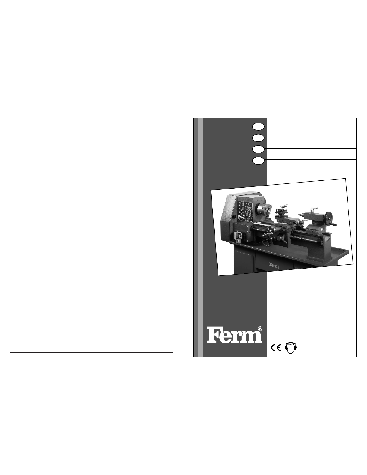
USERS MANUAL
Metal turning lathe 02
BEDIENUNGSANLEITUNG
Metalldrehmaschine 11
GEBRUIKSAANWIJZING
Metaaldraaibank 21
MODE D’EMPLOI
Tour à métaux 31
BRUKSANVISNING
Vinkelslipmaskin 20
KÄYTTÖOHJE
Kulmahiomakone 24
BRUKSANVISNING
Vinkelsliper 29
BRUGER VEJLEDNING
Vinkelslibere 33
Art.nr: 330950
Art.nr. 330960
GB
D
NL
F
MD-350/MD-500
Page 2

Ferm 51
BENCH LATHE MD-350 / MD 500
CAREFULLY READ THE INSTRUCTIONS BEFORE
YOU USE THE BENCH LATHE!
Carefully read this manual before using the machine. Make sure that you know how the machine functions and how
to operate it. Maintain the machine in accordance with the
instructions to make sure it functions properly. Keep this
manual and the enclosed documentation with the machine.
USE
The metal lathe has been designed for processing, mechanically removing metal, of ferrous and non-ferrous metals, synthetics and wood. The metal lathe is meant for semi-professional use and for leisure interests.
SAFETY INSTRUCTIONS
When using electric machines always observe the
safety regulations applicable in your country to reduce the risk of fire, electric shock and personal injury.
Read the following safety instructions and also the
enclosed safety instructions.
Keep these instructions in a safe place!
At the design of the machine is made allowance for the requirements for a safe use. Every change, adaptation, reconstruction or other adaptation use can cancel the safety
of the object. Besides the guarantee will expire through
this.
Before, after and during working with the lathe a number of
safety rules have to be taken. By the presence of turning
parts and sharp objects very severe injury can arise. Especially the bits of the turning chuck are very dangerous.
1. The lathe has been designed for manufacturing unruly
material and so it has to be able to develop a lot of power.
That is why touching turning parts is perilous. For this
reason unlawfully, undesirably or unintentionally switching on the machine has to be prevented, for example
by the pushed in locking of the emergency stop valve
by means of a small padlock.
2. By the elastic working of the chisel metal parts can
be shoot away with a big power at the most unexpected moments.
- Protection of the eyes is very important. Make it a habit
to wear special safety glasses when you are in the
space where the lathe stands. Buy yourself a professional and tested copy which you can wear for a long time and if need be for visitors a cheaper one, but this
one also has to be a good performance.
- If you take care of a cheerful workshop you can prevent
for example gripping in the machine or falling by stumbling over flinging about material.
3. Be very careful when you make turning pieces of
work with the hands.
- When you want to polish a surface turning, then take a
long piece of polish paper which you can place half
around the piece of work, with the ends to your direction.
- Never turn the ends around the fingers, never push
sand-paper on the piece of work with your hands.
- By turning, edges of the piece of work exist which are
sharp as a razor. These edges have to be smoothed off
with a file or a trimming hook.
4. Never remove chipcurls with your hands
Use a little hook which has been made by yourself of
thread or buy a professional chips hook.
5. Never grip over the turning machine or chuck
when during turning something falls in or behind
the bed.
Always first stop the machine. See that the covering
plate lies on the opening in the bed.
6. A good lighting prevents that you operate the machine from too close by.
- If you apply strip light you have to make allowance for
the so-called strobosto scopic effect. Through this a
turning object seems to stand still. A solution is the use
of double armatures by which a phase shifting of the
two strip lights has been accomplished.
7. Emergency stop
If a dangerous situation arises unexpectedly, for example if a badly exerted piece of work seems to get loose during turning, you van use the emergency stop by
giving a tap on the yellow cover of the safety switch,
marked “STOP”. The machine now stops without pushing in the switch button yourself.
GB
English
2 Ferm
SPARE PARTS FOR MD-350/MD-500
REF. NR. DESCRIPTION FERM NR.
0.01 Shears 400311
0.02 Intermediate gear spindle 400312
1.01 Locking handle 400300
1.03 Clamping nut 400301
1.05 Spindle 400302
1.06 Spindle bearing 400303
1.07 Handwheel for support 400304
1.08 Cover plate 400305
1.09 Spindle nut 400306
1.10 Tail stock 400307
1.11 Pinole MT-2 400308
1.12 Baseplate / bedplate 400309
1.13 Locking bolt 400310
2.02 Press handle 400313
2.03 Holder complete 400314
2.04 Axle pin tool holder 400315
2.05 Tool support (top) 400316
2.06 Sunk key 400317
2.09 Spindle 400318
2.14 Handle 400319
2.16 Nut (tool slide) 400320
2.17 Tool slide (under) 400321
2.18 Locking bolt 400322
2.20 Turning pin 400323
2.21 Key cross slide 400324
3.01 Handle 400325
3.04 Spindle 400326
3.05 Spindle nut 400327
3.10 Baseplate cross slide 400328
3.11 Hollow key 400329
3.13 Longidutinal direction spindle 400330
3.15 Hand wheel 400331
3.17 Half nut lever 400332
3.18 Half nut mechanism 400333
3.21 Longiditunal direction spindle (internal) 400334
3.22 Bearing 400335
4.03 Motor 400336
4.04 Motor pulley 400337
4.07 Headstock with cover 400338
4.08 Main spindle 400339
4.10 Main spindle pulley 400340
4.11 Intermediate pulley 400341
4.12 Tension roller 400342
4.16 Switch 400343
4.17 Bearing (lead screw) 400344
4.23 Thrust bearing 400345
4.24 Rack MD-350 400346
4.24 Rack MD-500 400367
4.24 Rack 400366
5.01 Gear 51 400347
5.02 Gear 68 400348
5.03 Gear 25 400349
5.04 Gear 75 400350
5.05 Gear 76 400351
5.06 Gear 24 400352
5.07 Gear 24 400353
5.08 Gear 76 400354
5.09 Gear 56 400355
5.10 Gear 56 400356
5.11 Change wheel 30 400357
5.12 Change wheel 42 400358
5.13 Change wheel 49 400359
5.14 Change wheel 28 400360
5.15 Change wheel 63 400361
5.16 Change wheel 70 400362
5.17 Change wheel 84 400363
5.18 Change wheel 98 400364
5.19 Change wheel 105 400365
- Center MC-3 400368
- Center MC-2 400369
- 3-Jaw chuck 400370
- 4-Jaw chuck 400371
- V-belt tension roller 400372
- Micro switch for door 400373
- V-Belt Z31 (10 x 790) 800114
- V-Belt Z28 (10 x 710) 800170
- V-Belt Z35 (10 x 890) 800197
- The reference numbers refer to the 5 annexes indicated
with the numbers 0, 1, 2, 3, 4, 5.
The number in front of the point refers to the Annex, the
number behind the point refers to the part.
So, reference 4.07 refers to Annex 4, part 7
- Die Referentienummer referieren auf 5 Beilage die Mittels
den Nummern 0, 1, 2, 3, 4 und 5 angegeben werden.
Die Nummer vor dem Punckt verweißt auf die Beilage, die
Nummer hinter dem Punckt auf das Unterteil. So die Verweißung 4.07 referiert auf Beilage 4, Unterteil 7.
- De Referentienummers verwijzen naar de 5 bijlagen aangegeven met de nummers 0, 1, 2, 3, 4 en 5.
Het nummer voor de punt verwijst naar de bijlage, het nummer achter de punt naar het onderdeel
Referentie 4.07 verwijst dus naar bijlage 4, onderdeel 7.
- Les numéros de reference se référent à les 5 annexes, indiquées avec les numéros 0, 1 ,2 ,3, 4 et 5. Le numéro devant
le point se réfère à l’annexe, le numéro à derrière le point se
réfère à la pièce détachée. Par conséquant la référence
4.07 se réfère à annexe n°4, pièce détachée n°7.
Page 3
R
R
R
R
R
R
50 Ferm
TECHNICAL SPECIFICATIONS
Mains voltage 230 Volt
Mains frequency 50 Hz
Absorbed power 375 Watt
Center height 110 mm
Center distance MD-350 350 mm
Center distance MD-500 500 mm
Max. turndiameter above bed 200 mm
Max. turndiameter above support 115 mm
Culvert and recording main shaft 18 mm, MT-3
Number of speeds main shaft 6
No load speeds main shaft 120-2.000/min.
Automatic start 11 mm; 0,04 - 0,3
Thread cutting (right) 11 mm; M0,4 - M3
Distance toolholder centerline -
measured vertically 15 mm
Rotating plate movement: 3600
Graduation rotating plate: ± 450
Movement tool cut 70 mm
Movement cross slide 115 mm
Movement end slide 350 mm
Graduation slide screws 0,04 mm
Recording and stroke slide tube 50 mm; MT-2
Graduation slide tube 0,05 mm
Weight MD-350 110 kg
Weight MD-500 130 kg.
Sound pressure L
wa
70 dB(A)
Vibration value 2,8 m/s
2
THE MD-350 AND THE MD-500 ARE DELIVERED IN
THE FOLLOWING BASE PERFORMANCE.
Machinebed with prism conductor, ferme head with main
shaft and drive for automatic longitudinal feed and thread
cutting, tail stock with sliding tube and transverse adjustment, electro motor with start/stop- and sense of rotation
switch, support with lock case, combined with
starting/lead screw, cross slide with rotating plate and tool
slide, fourfold tool holder with index pin, 3-chuck with extra
exterior basins and measuring certificate, drive protection
case, 7 change wheels, 3 driving-belts, 2 centers, 3 openend spanners, 2 socket head wrenches, catch pin and a
tightening-wrench chuck.
Excluded under-carriage (art. nr.330957).
INSTALLATION
SPACE.
Next to a good maintenance it is very important the machine is installed drily, as the machine has been built up for de
biggest part of metal. Spaces can become moist by insufficient or a wrong ventilation, burning not regularly or by
raced walls and lifting moisture. Condensation of moisture
on the metal is caused by suddenly raising the temperature in a cold space. See that the temperature is equable.
UNPACKING AND INSTALLING
The machine is packed in a strong case which you can dismantle to six flat parts which can be put away easily. These
parts can be saved in case you have to transport the lathe,
for example for repair or for a removal. After you have opened the case the lathe has to be detached from the pallet.
For this you have to remove two nuts, in each bedfoot one.
Later the nuts can be used again. For lifting up the lathe
you may call in the help of an assistent, this depends on the
weight. Before you begin you have to arrange how to lift
the machine. You should rather put the machine from the
pallet on the permanent destination at one go. The best
thing is to grip the machine at the ends of the bed, so do not
grip it on the heads, transporter, change wheel case or
motor! The apparatus weights roughly 110 kg. For reducing the weight temporary a number of parts can be removed carefully, like the tail stock, the turning plate with building and the discs from iron cast. The lathe has to be level
and it has to be installed on a strong bottom. If you make an
under-carriage yourself you can use a steel U-profile of
sufficient lenght, on which you can sold or screw a leg construction. You can also use a strong wooden lower case
with a strengthened and flat upper blade, for example by
means of a piece of multiple worktop. The conditi on is that
the formation has to be stiff in every directions and that it
cannot fling about, bend or wobble. The lathe is fixed with
two bolts M10 in the special gaps in both bottom plates.
TIP:
You can take the following precautionary measures
for preventing that small roughnesses still cause tension
on the bed if you tighten the two bolts. You draw the place
of the two bottom platesand the two assembling gaps and
you assemble two bolts M10 in the foundation. Put on the
drawn places a layer epoxy filling. Install a plastic foil on
this. See that the bolts stay clear! Then install the workbench on the drawn place. Use the two bolts for this as the
conductor. Let down the bed on the foil and then harden
the filling. After that you can provide the bolts with the nuts
which are also used for the transport, and then you can
tighten these ones again.
ELECTRICAL CONNECTION
After the motor has been installed permanently a connection to the electrical installation has to be made. The machine has been made for use on the existing 230 Volts alternating current mains and hasn’t a power bigger than other big household equipment with a motor. Have an eart-
Ferm 3
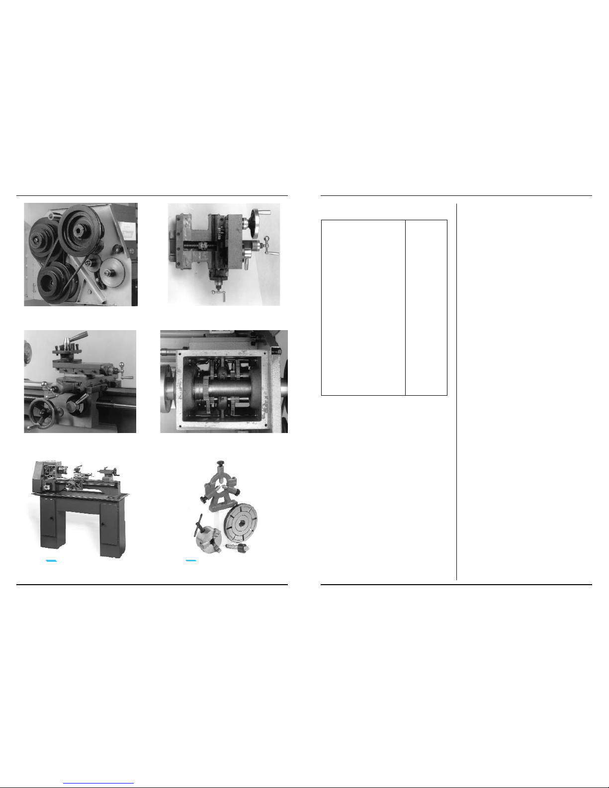
Floor Stand / Unterschrank / Onderstel /
Bas de casse. Art.nr.: 330957
Accessories/Unterteile / Onderdelen /
Accessoires
V-Belt / Riemen / V-Snaar / Courroies t
rapézoïdales
Bottom side Support/Unterseite Support / Onderzijde support / Surface inférieure de support
The Suppory/Das Support / Het support /
Le support
Oil bath in gearbox/Ölbad im Zahnräderkasten
Oliebad in de tandwielkast/ Bain d’huile de boîte d’engrenage
Page 4
Ferm 49
hed power point installed in the nearness of the machine
and see that the lead can be guided to the contact without
cracks and pulls. If need be an earthed extension cable
can be used, but see that the cable is unrolled entirely and
that it is not in the way.
ELECTRICAL SAFETY
Always check that the power supply corresponds to the
voltage on the rating plate.
REPLACING CABLES OR PLUGS
Immediately throw away old cables or plugs when they have been replaced by new ones. It is dangerous to insert the
plug of a loose cable in the wall outlet.
BEFORE OPERATION
For transport the machine has been greased with a layer
which prevents rust. This layer has no greasing function
and has to be removed with clothes. You can do this with a
solvant which is not aggressive, for example turpentine or
petroleum. When you are acquainted with metal-working
machines you can dismantle, control and oil several spare
parts with a light and universel machine-oil, for example
sewing-machine oil (sour free). Afterwards you finish the
complete maintenance table of chapter 14 ‘maintenance’.
ADJUSTMENT
The lathe has been adjusted to a minimum margin by the
factory. Because of transport some adjustments can be
changed. On the other hand the machine has been designed in such a way that any appearing margin can be lifted. This margin is also caused by wear end tear as a consequence of an intensif use. If re-adjustment does not have an effect anymore, the part is worned and has to be moved.
SPARE PART
Spindle tool slide
Tool slide
Spindle cross
slide
Cross slide
Transmission/
starting shaft
Tailstock
LIFTING A MARGIN
Loosen the front lock
nut, distort the back
lock nut clockwise,
until margin is minimum, turn back a
fourth part and tighten
the front lock nut
Loosen the lock nuts,
tightening the
adjusting nuts
clockwise until margin
is minimum, tighten
lock nuts
Watch spindle tool
support
Watch tool slide idem
Loosen front lock nut
and tighten hindmost
lock nut until margin is
no longer noticeable,
turn back a quarter
part and tighten the
front lock nut
Loosen clamping nut,
unscrew both adjusting nuts on both sides
a quarter part.
Move head with
adjusting screws until
the mark signs on the
right side of the head
correspond, tighten
the adjusting screws
again a bit without
moving the head, fixing the clamping nut.
RECOURCES
2 hook
spanners
screw-driver,
open end
wrench
idem
idem
idem
screw-driver,
open end
wrench
4 Ferm
Page 5
48 Ferm
If all preparations have been done the machine can be
connected to the mains by putting the plug into the power
point. Beforehand check if the mains switch is “OFF” and
check if the turning directions is “RIGHT”. Watch the gauge once more and see if the oil level has not changed and if
necessary you have to fill it till the gauge half-full. See that
there is no paper or cleaning-rag for the ventilati on openings of the motor. Check the three-jaw and see that the
basins cannot come out of the jaw.
PUT THE JAW-WRENCH ON A PERMANENT
PLACE!
Open the protection case and check the position
and tension of the belts. For running on trial the lowest turning speed has to be chosen. You may shift the front belt,
watch fig.5 and 15.
Push in the switch and have the machine turned during 20
minutes. Check regularly if the head bearings in the headstock and the motor do not become hot by stopping the
machine and putting a hand on both side of the headstock
and on the motor body. Immediately stop if you hear a deviating noise and if you feel an abnormal heath development( more than handwarm) and first con tact your supplier.
Then switch over to a higher speed and have the machine
also function a few minutes on this speed. Do this again
with a reversed turning direction. If no problems have arisen, the machine is ready for use.
WORKING METHOD
Removing metal takes place by pushing under control a
chisel point or a boring point in the piece of work through
which small pieces of material - chips - are cut away. For
this the piece of work has to make a turning movement between two fixed turning points- the headstock and the tail
stock (watch fig.1) - which lie on a very precise, imaginary
line: the centerline(4). This can be turned off paral lelly to
the centerline over the whole lenght, by carrying the chisel
which has been fixed on the support(5) in a certain tempo
along the turning piece of work. This has to be done in a
straight line, with the hands or automatically with the transmission(6).
For removing material of the piece of work, power is needed. This power is transmitted from the motor to an empty
shaft in the headstock: the main shaft (2). In connection
with the maximum motorcapacity the quantity material
which has to be taken - the chip thickness and the width of
chip- has to be adapted. If the number of revolutions lowers too much, the starting depth or the rate of speed has
to be lowered. Otherwise there is a chance of motor damage, shorter tool life of the chisel or the chisel rupture. The
diameter of the piece of work is also influences this. If you
have a diamter of 100 mm more power is needed for cutting a chip of 1 mm than at a diameter of 10 mm.
When the tail stock (8) is placed next to the centerline because of cross adjustment, an outward conical plane is turned. An extra processing possibility over the lenght axle is
cutting a screw-thread. A special chisel cuts a spiral deepening in the outline of the piece of work. A part of the out-
line keeps on standing and this height difference forms the
ultimate screw-thread. Next to turning over the lenght axle, the ends of a piece of work can also be processed, for
example for making them flat and straight. Short pieces of
work can be fixed at one side in a fixed turning-point, the three-jaw chuck, and on the other side be processed at right
angles to the centerline. The basins of the chuck see to
maintenance of an imaginary centerline. By having occurred the chisel replace ment under an angle by adjustment
of the chuck, inward and outward conical planes can be
turned. With this strain borings can also be made in levelled surfaces. For that a drill chuck has to be bought separately. This drill chuck with morse cone peg has to be installed in the sliding tube (7) of the tail stock. Then the gaps
can be screwn out until the desired depht, diameter and
form.
IMPORTANT:
The precision of the pieces of
work is first and particularly depen dant of expertness and experience. During turning many
factors can influence the end result, like the sort and the
condition of the chisels, the nature of the material you want
to process, the turn and starting speed, the fixation of the
piece of work, the drafting and the condition of the machine. With the MD-350 it is possible to manufacture prolonged pieces of work with a big accuracy, if all circumstances
are perfect.
FOR THE BEGINNING TURNER.
During turning big powers on certain parts can be developed. If you use the machine incorrect these parts can be
damaged or deformed and wear end tear faster, even if
they have been made and designed very expertly and carefully. Through this the accuracy of the machine will decrease strongly, which directly influences the quality and
tahe preciseness of your pieces of work. So it is important
that the apparatus is tended in an expert way. Recommended is, if you are not a skilled turner, to start with simple pieces of work and to try the different possibilities of the lathe
with trial pieces of work. It is instructive to look at skilled turners, because you are not that fast a perfect turner! For pre
venting disappointments you have to become familiar with
the basic principles of turning. Turning is not for nothing a
profession. You can find referencebooks about metal working and metal turning in the library or in a book-shop. Besides model-building magazines write about this subject regularly. The best is getting into possession of a, if need be
obsolete, technical text-book. In this book is told about the
general principles of turning and many things worth knowing and handy summaries of problems with possible
causes and solutions.
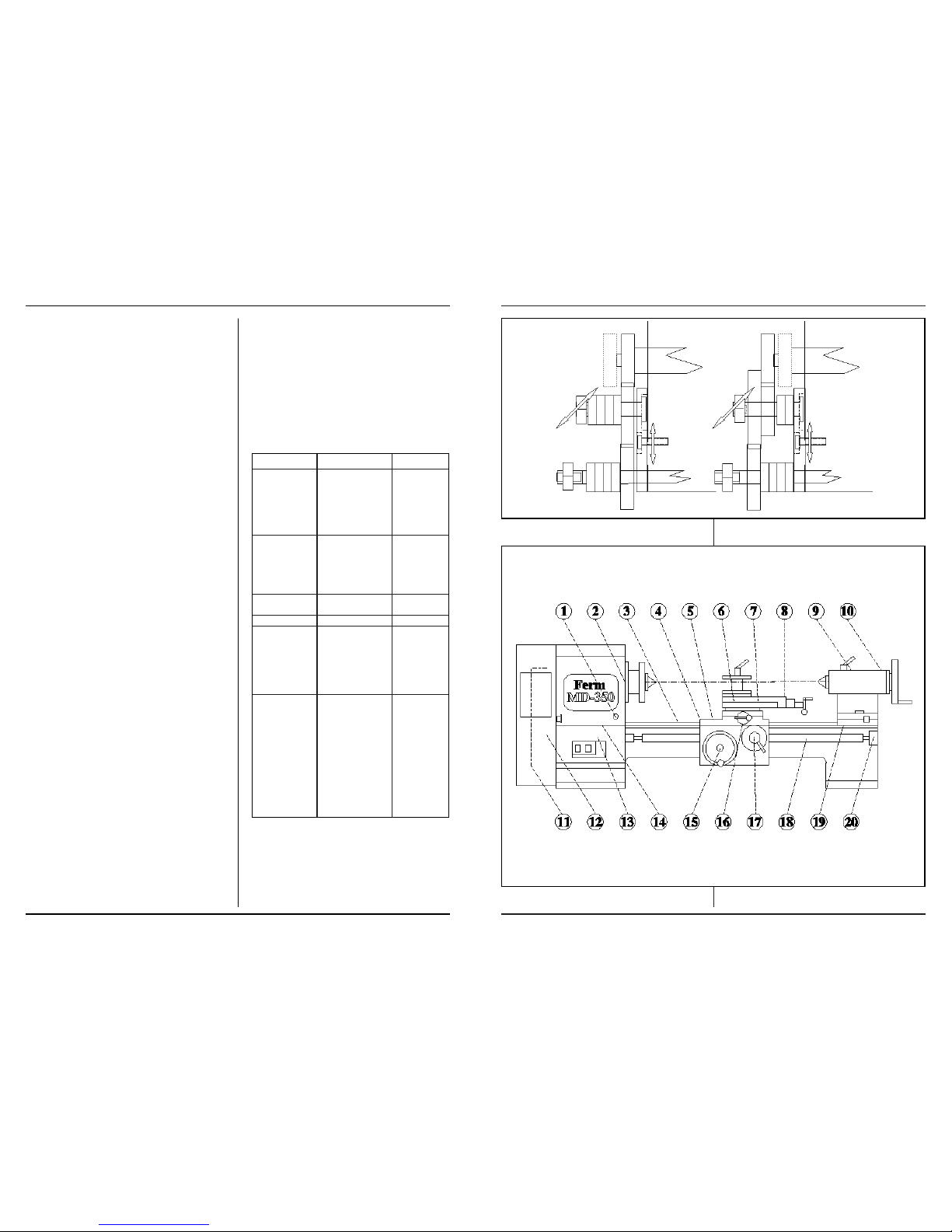
FUNCTION OF THE MACHINE.
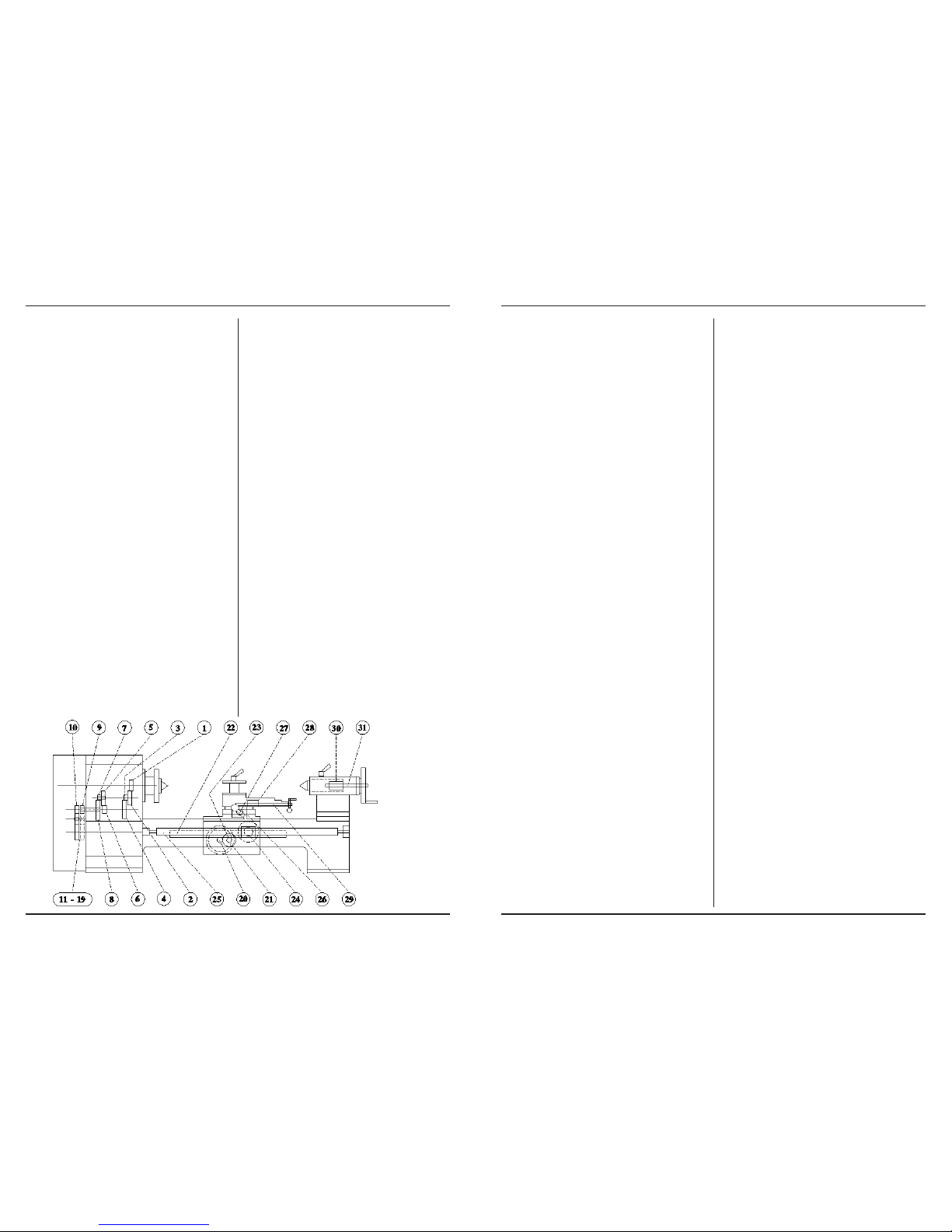
For a good understanding of the working of the machine
this one can for conve nience sake be divided in a number
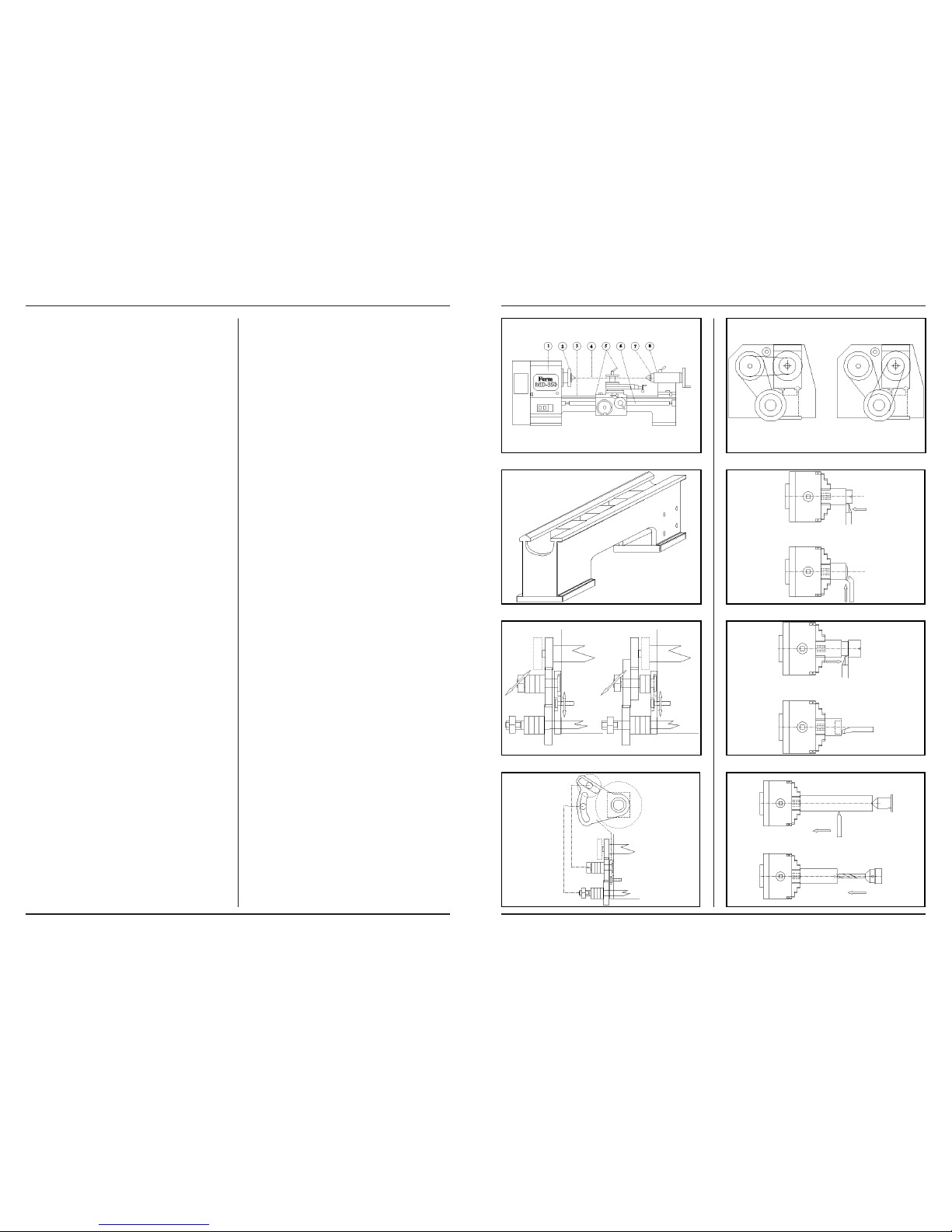
of main groups and components, all with a special function. Watch fig.1.
Ferm 5
Page 6
Ferm 47
THE MACHINE BED
The machine bed connects all these parts and has next to
it also other important functions. The bed (3) has been manufactured of highgrade grey cast iron and it is provided
with several filled cross ties. Because of the design and
the applied sorts of material tremblings are better absorbed and deforming because of charge is minimum. The
bed is provided with two sliding surfaces sharpened very
precisely, for the conducting of support and tail stock. These conduc tings, one prismatic and one flat, see to maintenance of the centerline(4).watch fig.2.
THE MOTOR
The attached alternating current motor is a carbon brushless 1-phase squirrel- cage motor with starting condenser.
The motor is maintenancefree and does not need a special treatment. By means of V-belts and plural belt discs,
the pulleys, the movement of the motor is transmitted to
the mains axis.
THE HEADSTOCK
The poured headstock(1) has been fixed on the bed with a
prism conducting and two face plates. On the back side is
an oil draining nut. The cover is remo vable for inspection
and for putting oil. At the bottom of the head you can find a
system of turning axis and toothed wheels. Because of
these toothed wheels the speed of the main shaft is retarded and transmitted to a double, coaxial output axis. On
this axis you can find the driving gear for the start and the
driving gear for the thread-cutting, watch fig.3. In the head
you can find the most important part of the machine, the
main shaft(2).
This one has been fixed revolving with two conical roller
bearings in an O- drafting. All turning parts in the head are
lubricated by means of an oil bath. The level of this is readable in the window on the front side. The main shaft has
been provided with a going on boring with on the right side
a fixing flange and a morse cone, for respectively the
chucks and the center.
THE SUPPORT
On the sliding surfaces on the bed the support(5) has been
fixed which sees that conducting tools along the piece of
work is checked. First the support consists of a bed slide
with lock case. This slide lies on the bed and serves as movement in the lenght direction. This movement can occur
with the hands or automatically by the transmission/feeding axis(6). In the last case the coach bolt has to be closed in the lock case. On the bed slide a second slide has
been installed which takes care of the chisel movement in
cross direction. By means of a spindle with follow nut this
slide can be moved or adjusted. On the cross slide a chuck
has been installed. With this the upper slide or tool slide
can be adjusted under an angle. The third and upper slide,
tool slide, can be replaced in any desired direction over a
distance of 70 mm and it follows every movement of all underlying slides also the chuck. On top of the tool slide a tool
holder has been installed. In this tool can be exerted to a
point height of maximum 15 mm, the vertical distance to
the centerline. The tool holder has a fourfold absorption
and has an indexing pin with four click points. Through this
can be changed of chisel very fast without having to adjust
again.
THE TAIL STOCK
The end of the centerline is formed by the tail stock (8). The
axis of the fixed and tail stock are exactly in each others extension. Depending on the lenght of the piece of work the
head can be moved over the bed and it can be fixed. With
the slide bush (7), in which a center has to be installed, the
piece of work can be exerted fixed and revolving right on
the centerline. If you turn back the slide bush, the center is
automatically untied. The body of the head has been divided. The upper part can be adjusted sideways with regard
to the upper part by means of adjusting screws. Through
this an adjustment next to the centerline can be obtained.
Normal movements in the lenght direction do not have
side ways adjustments as a consequence.
THE COMBINED TRANSMISSION/STARTING AXLE
For a good surface quality a correct and particularly a constant rate of turnover in the longitudinal direction is important. For longer pieces of work this is almost impossible
with your hands. By closing the lock nut the support is
coupled with the thread on the transmission. When the
transmission has been switched on this one has been
coupled to the main shaft in his turn. With this a coupling is
made with an intermediate wheel between the drive wheel
of the transmission and the drive wheel for the longitudinal
feed on the headstock. This happens because of an adjustment of the change wheel scissors, watch fig. 3 and 4.
At each rotation of the main shaft the support will move itself over a certain distance along the bed. This distance
depends on the wire haste and the chosen wheel change
on the transmission. By chosing another wheel change
the star ting speed can be adapted.
With thread-cutting the same happens in principle, however with a much bigger support movement with a much lower main shaft speed. In this case a coupling has to be made with the thread-cutting driving gear of the headstock.
The positioning of the gear wheels happens by the installation of the rings on the starting axle and intermediate
wheel axle of the scissors. In this case change of the change wheel on the transmission makes possible a choice of
the haste of the thread which has to be cut. On the transmission is no automatic cut out. So switch this one off for
preventing that the chisel runs against the chuck.
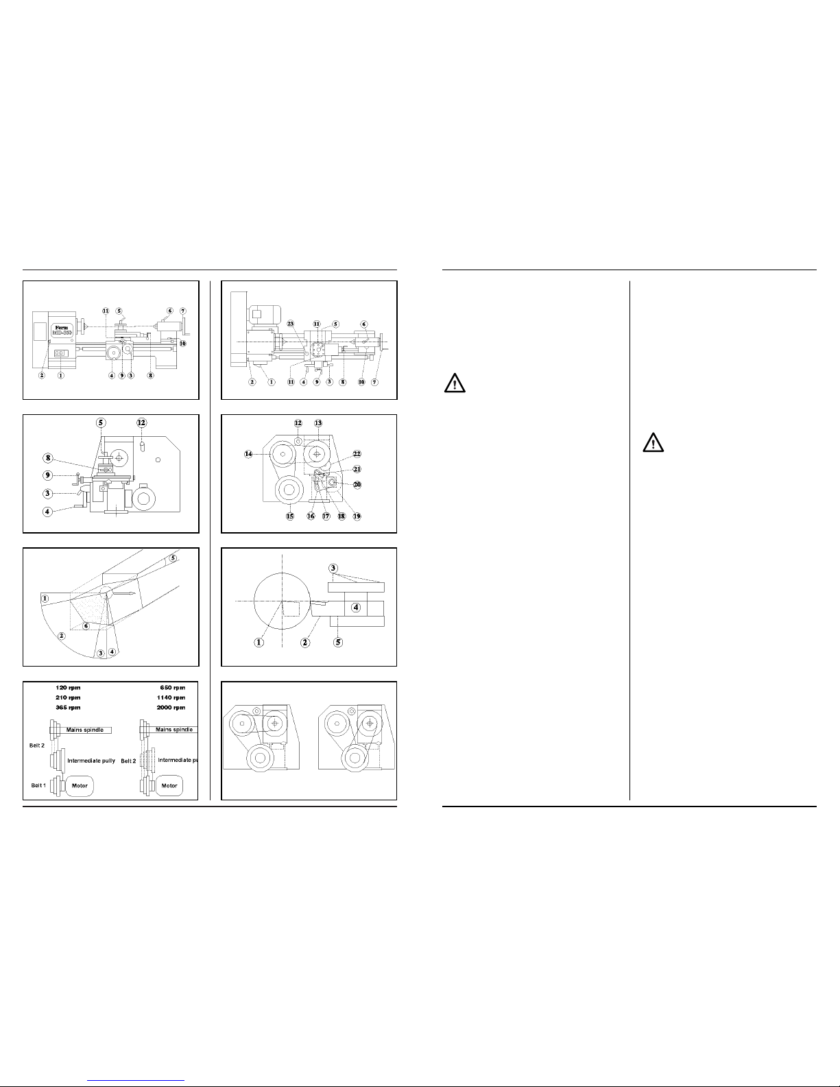
THE DRIVE
Since the applied motor has a fixed and relatively high
number of revolutions the transmission has been done in
such a way that this reduces the numbers of revolutions at
the same time. Besides, with the application of plural pulleys and an intermediate pulley this number of revolutions
is variable in six successive steps.
For lifting up possible belt tension differences the bearingmounted belt pressure roll has been made variable.
Watch fig.5. For reaching the three highest spindle
6 Ferm
Page 7
46 Ferm
speeds the front belt has to be shifted from the intermediate-pulley to the motor pulley. The intermediate gear keeps
driven and serves as flywheel for catching load variations.
BASIC PRINCIPLES OF THE TURNING
Before you can start turning, you have to know the most
important basic under standings. Otherwise there is a
change that the wrong turning speed or the wrong chisel is
chosen. With a number of tables and rules making the machine ready for turning is easier.
CLAMPING
Clamping the piece of work has to happen with care. Put
the piece of work in the chuck as far as possible and clamp
this one with the tightening wrench. If you clamp too hard
the chuck, basins or the piece of work can be damaged.
The same applies for the sliding tube. Tighten this one with
your hands, strong but not by force. Some clamping examples by which also the use of bores and chisel is made
clear, can be seen in fig.6, 7 and 8.
The represented standard three-chuck is self-centring.
Through this the axis of a small piece of work falls exactly
on the centerline, even if the dead centre is not used. With
a chuck belongs an inside basin (represented) and an
outside basin. These ones are used for inside clamping of
bigger diameters. Every basin has in the chuck the same
place. Place and basin are numbered!
In fig.6 a right side cutting chisel (up) and a right bended
roughing tool is used. The arrows indicate the starting direction. The roughing tool can be used in longitudinal direction and in cross direction and is often used for quickly
elimina ting many material. Fig 7. shows the use of a left
side cutting chisel and a blind boring chisel. Fig.8 shows a
clamp with dead center in a tail stock. A pointed chisel has
been used for an egal finish. Under this figure a clamping is
represen ted for making a bore with a spiral drill. Beforehand you have to pre-drill with a center bore. This is a bore
from which the shank is much thicker than the crossing
frog. The boring gap which arises through that serves as a
center gap for both the center and the bore!
OPERATION OF MD-350 AND MD-500
Survey of the operation points with corresponding function (see fig.9,10 11 and 12).
1 Combined on/of direction of rotation switch with
emergency feature blocked.
Switching on the motor and chancing the direction of
stop rotation, the valve kan be blocked with a lock.
2. Drive cupboard closing
For opening and closing of the case
3. Carriage nut handle
By closing the carriage nut, the
automatic starting is
switched on.
4. Handwheel longitudinal adjustment.
For quickly moving the support to the left and to the
right. On the nonius can be written how big the adjustment is in steps of 0,04 mm.
5. Clamping handle tool holder
By unloading the handle the bit block can be turned in
steps of 90 °
6. Clamping handle sliding bush.
For fixing the sliding bush.
7. Handwheel sliding bush
By turning the piece of work can be clamped between
the chuck and the center; also used for boring; on the
nonius can be written how big the adjustment is in
steps of 0.05 mm.
8. Handwheel crank tool slide
for the longitudinal adjustment of the tool slide; on the
nonius can be written how big the adjustment is in
steps of 0.04 mm.
9. Handwheel crank cross slide
for the longitudinal adjustment of the cross slide; on
the nonius can be written how big the adjustment is in
steps of 0.04 mm.
10 Clamping nut tail stock
for clamping the tail stock to the bed; for clamping the
upper part to the bottomplate.
11 Clamping nuts rotary plate
After the desired corner has been adjusted the rotary
plate parts can be clamped on each other with this.
12 V-belt tension roller
Makes it possible to change V-belts, to clamp and shift
them without dismantling the pulleys.
13 Main shaft pulley
Adjusting rotary speed.
14 Intermediate pulley
Adjusting rotary speed.
15 Motor pulley
Adjusting rotary speed.
16 Scissor
for assembling an intermediate change wheel and being able to adjust this in three directions. Coupling
transmission
17 Clamping bolt link adjustment
By adapting the position of the quadrant the intermediate drive wheel and the transmission change wheel
Ferm 7
Annex 5/Anlage 5
GEAR WHEEL, SPINDLE AND WASHERNUT DATA
ANGABEN ZU ZAHNRAD, SPINDEL UND UNTERLEGMUTTER
Nr. Parts/tooth Pitch/mod. Spec./Dim.
Nr. Zubehörteil/Zähne Gew. St. Bes./Abm.
MAIN SHAFT/HAUPTWELLE
1 Gear wheel/Zahnrad/51 /1 /D8
2 Gear wheel/Zahnrad/68 /1 /D8
3 Gear wheel/Zahnrad/25 /1 /D8
4 Gear wheel/Zahnrad/75 /1 /D8
5 Gear wheel/Zahnrad/76 /1 /D8
6 Gear wheel/Zahnrad/24 /1 /D8
7 Gear wheel/Zahnrad/24 /1 /D8
8 Gear wheel/Zahnrad/76 /1 /D8
9 Gear wheel/Zahnrad/56 /1 /D8
10 Gear wheel/Zahnrad/56 /1 /D8
CHANGE WHEELS/WECHSELRÄDERN
11 Gear wheel/Zahnrad/30 /1 /D8
12 Gear wheel/Zahnrad/42 /1 /D8
13 Gear wheel/Zahnrad/49 /1 /D8
14 Gear wheel/Zahnrad/28 /1 /D8
15 Gear wheel/Zahnrad/63 /1 /D8
16 Gear wheel/Zahnrad/70 /1 /D8
17 Gear wheel/Zahnrad/84 /1 /D8
18 Gear wheel/Zahnrad/98 /1 /D8
19 Gear wheel/Zahnrad/105 /1 /D8
SUPPORT/SUPPORT
20 Gear wheel/Zahnrad/17 /1 /D8
21 Gear wheel/Zahnrad/51 /1 /D8
22 Gear rack/Zahnstange /2 *) /L425
23 Gear wheel/Zahnrad/17 /2 *) /D8
24 Lock nut/Schloßmutter M3/ *) /L30
25 Starting shaft/Anlaufwelle *) /L425
26 Washer nut/Unterlegmutter M2/ *)
27 Spindle/Spindel *)
28 Washer nut/Unterlegmutter M2/ *)
29 Spindle/Spindel *)
TAILSTOCK/REITSTOCK
30 Washer nut/Unterlegmutter M2/ /L27 *)
31 Spindle/spindel /L50 *)
*) This parts are already mentioned in the list op parts.
*) Diese Teile sind bereits im Zubehörverzeichnis erwähnt.
Bijlage 5/Pièce annexe 5
TANDWIEL-, SPINDEL- EN VOLGMOERGEGEVENS
ROUE DENTÉE, BROCHE ET DONNÉES D'ÉCROUS D'ORDRE
Nr Onderdeel/tanden spoed/Mod. bijz./afm.
N° Pièce detachee/N° dents urgence/mod. part./dim.
HOOFDAS/ESSIEU PRRINCIPAL
1 tandwiel/roue dentée/ 51 /1 /D8
2 tandwiel/roue dentée/ 68 /1 /D8
3 tandwiel/roue dentée/ 25 /1 /D8
4 tandwiel/roue dentée/ 75 /1 /D8
5 tandwiel/roue dentée/ 76 /1 /D8
6 tandwiel/roue dentée/ 24 /1 /D8
7 tandwiel/roue dentée/ 24 /1 /D8
8 tandwiel/roue dentée/ 76 /1 /D8
9 tandwiel/roue dentée/ 56 /1 /D8
10 tandwiel/roue dentée/ 56 /1 /D8
WISSELWIELEN/ROUES DE RENVOI
11 tandwiel/roue dentée/ 30 /1 /D8
12 tandwiel/roue dentée/ 42 /1 /D8
13 tandwiel/roue dentée/ 49 /1 /D8
14 tandwiel/roue dentée/ 28 /1 /D8
15 tandwiel/roue dentée/ 63 /1 /D8
16 tandwiel/roue dentée/ 70 /1 /D8
17 tandwiel/roue dentée/ 84 /1 /D8
18 tandwiel/roue dentée/ 98 /1 /D8
19 tandwiel/roue dentée/ 105 /1 /D8
SUPPORT/SUPPORT
20 tandwiel/roue dentée/ 17 /1 /D8
21 tandwiel/roue dentée/ 51 /1 /D8
22 tandheugel/crémaillère /2 *) /L425
23 tandwiel/roue dentée/ 17 /2 *) /D8
24 slotmoer/écrou de verrouillage M3/ *) /L30
25 aanzetas/arbre d'entraînement *) /L425
26 volgmoer/écrou d’orde M2/ *)
27 spindel/broche *)
28 volgmoer/écrou d’ordre M2/ *)
29 spindel/broche *)
LOSSE KOP/CONTRE-POUPÉE
30 volgmoer/écrou d’ordre M2/ /L27 *)
31 spindel/broche /L50 *)
*) Deze onderdelen staan reeds vermeld in de onderdelentabel.
*) Ces pièces détachées sont déjà mentionnées dans le tableau
des pièces
5
Page 8
Ferm 45
can be placed. Switching the transmission on and off.
18 Intermediate change wheel
Direction of rotation transmission; adjusting the transmission ratio
19 Chance wheel transmission.
Adjusting transmission ratio; by means of placing filling rings the wheel can be adjusted in axial
direction(fig.3)
Longitudinal motion support
20 Transmission/lead screw
fixation intermediate change wheel; by means of installing the filling rings he wheel is axial adjustable and
with the lowest shaft nut the wheel is adjustable sideways
21 Intermediate change wheel.
In front of the thread-cutting wheel, behind the starting
wheel
22 Drive gear wheels for start.
by using this clamping device for surfacing and threadcutting the lock nut can stay open and the support
does not slip away; spindle and nut are less charged
then.
23 Clamping bolt cross slide.
CHISELS
During turning a chip is cut out of the piece of work. For this,
chisels have to be sharpened in a special and sharp form.
This form depends on the chisel material and on the material you want to cut. Watch the next table.
On the basis of fig. 13 the corners of this table can be taken
over on a little piece square high-speed steel for making or
re-sharpening your own chisel. In this example we are talking about a straight, right roughing tool. The dotted lines
indicate the original form of the bar. The sum of the angles
1,2 and 3 is always 90°. Angle 1 is the cutting-edge side rake, angle 2 the wedge angle and angle three the clearance
angle. For keeping the friction as low as possible, two extra clearance angles have been sharpened: angle 4 and
angle 6. Besides, a slope angle 5 has been installed. The
arrow indicates the starting direction. The front face is called the minor cutting face. The main cutting face is the part
on which the arrow has been drawn. In this way all possible
chisels can sharpen themselves, by which you have to say
where the main cutting face has to be and what the turning
material has to be.
A perfectly sharpened chisel has to be placed in the tool
holder in the right way now. Fig.14 indicates a correct pla-
cing of a pointed chisel. Point 1 is the center line. The tip of
the chisel has to stand exactly that high. If not, you have to
use bearing plates(5). The chisel always has to be placed
against the block body(4) and cannot extend farther than 1
to 1.5 time the tool shank thickness(2).
It goes without saying that all clamping bolts (3) have to be
tightened strongly.
TURNING SPEED
If the chisel have been sharpened and put, the piece of
work has been clamped well, the speed of the main shaft
has to be adjusted with the V-belts, watch fig. 15 and 16. In
the subjoined table some machining speeds which happen many times are indicated for different sorts of chisels
and materials.
With this table you can chose yourself for any diameter the
right speed. The only thing you have to do is fill in the desired speed in the following formule.
v = cutting speed in meters per minute
d = diameter of the piece of work in mm
n = number of revolutions in revolutions per minute
π = constant, nl. 3,14
Calculation example:
1. A round piece of silver steel of 100 mm has to be turned
with a HSS chisel. You can find in the table that silver
steel has to be turned with 32m/min, v=32
Divide 32.000 by 100 gives a number of revolutions of
320 revolutions per minute. We put belt 2 on the hindmost discs of the intermediate and main shaft pulley.
2. A piece of copper of 10 mm is turned with a HM-chisel.
v=200 and through that “n” comes far above the maximum number of revolutions. The highest number of revolutions can be adjusted. Belt two is layed on the
hindmost disc of the motor and main shaft pulley.
v =
π ¥ d ¥ n =v ¥ 1000
1000 π ¥ d
Turning material Chissel Turning speed
material REV/MIN
Unalloyed structural steel HSS 40 - 60
(9S20k - 60S20k) P10 140 - 160
Alloyed structural steel HSS 32
Tool steel P10 112
(C80= Silversteel)
Cast Iron HSS 40
K10 100
Non-Ferrous HSS 45 - 80
(Cupper, Aluminium) K10 140 - 280
Chisel corners Light cut Normal cut Heavy cut
HSS HM HSS HM HSS HM
cutting-edge
side rake
12 10 10 5 5 0
Clearance
angle
867564
Wedge
angle
70 74 73 80 79 86
8 Ferm
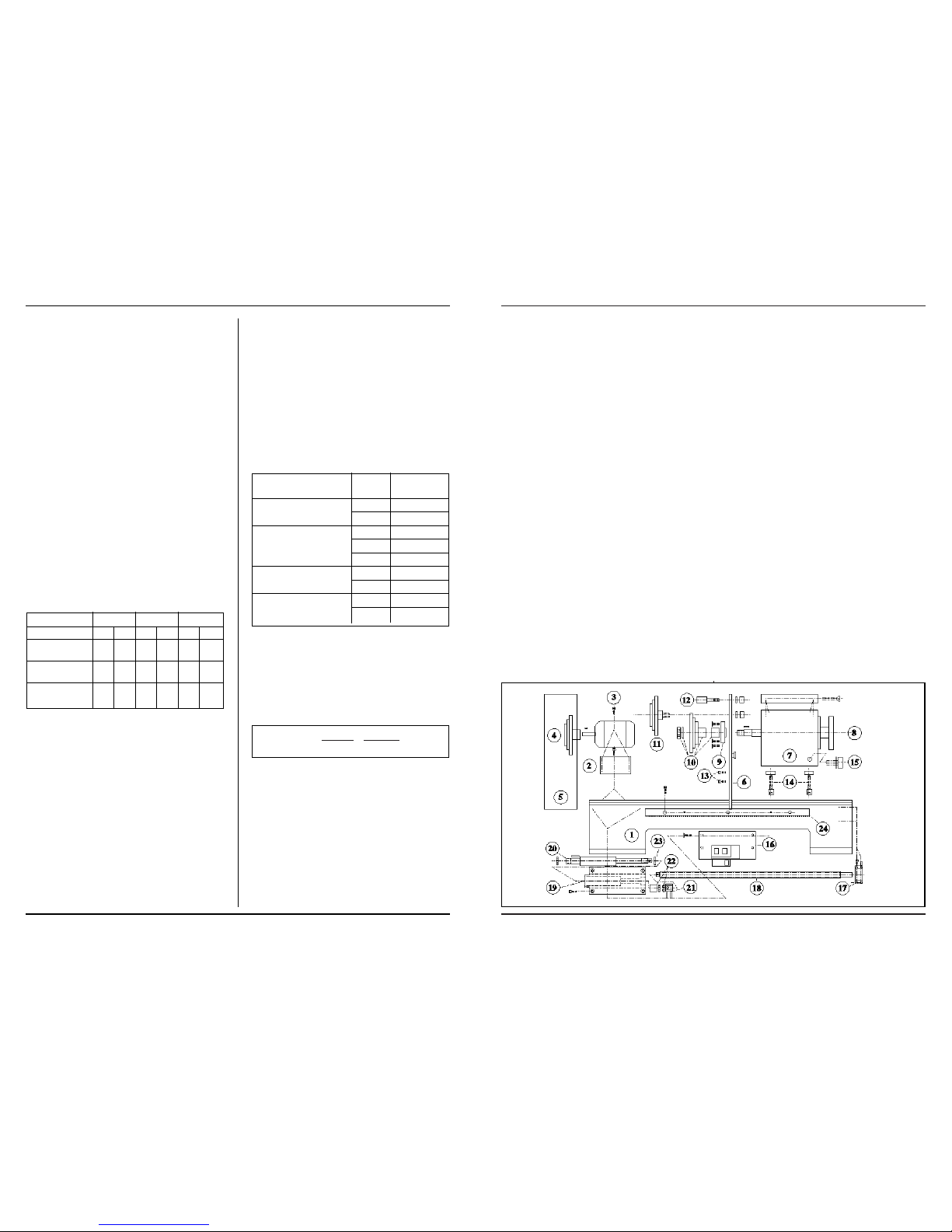
Annex 4
List of parts
BED/HEADSTOCK
Nr. Part
1. Bed
2. Motor base plate
3. Motor
4. Motor pulley
5. Guard
6. Mounting plate
7. Headstock with cover
8. Mains spindle
9. Bearing cover
10. Main spindle pulley
11. Idler
12. Tension pulley
13. Bolts with ring
14. Chuck headstock
15. Oil cup
16. Switch
17. Longitudinal and traerse
motion bearing
18. Longitudinal traverse (lathe
spindle
19. Bearing housing drive shaft
20. Drive shaft longitudinal and
transverse motion
21. Bush
22. Castle locking nuts
23. Axial thrust bearing
24. Gear rack
Anlage 4
Zubehörverzeichnis:
MASCHINENBETT/
SPINDELSTOCK
Nr. Zubehörteil
1. Maschinenbett
2. Motorstellplatte
3. Motor
4. Motorriemenscheibe
5. Schutzkasten
6. Befestigungsplatte
7. Spindelstock mit Deckel
8. Hauptwelle
9. Lagerdecke
10. Hauptwellenriemenscheibe
11. Zwischenriemenscheibe
12. Spannrolle
13. Bolzen mit Ring
14. Spannplatten Spindelstock
15. Ölstopfen
16. Schalter
17. Fördererlager
18. Längsvorschub (Leitspindel)
19. Lagergehäuse Antriebswelle
20. Antriebswelle Fördere
21. Kupplungsschale
22. Kronensicherungsmuttern
23. Axialdrucklager
24. Zahnstange
Bijlage 4
Onderdelenoverzicht
Bed/Vaste kop
Nr.
Onderdeel
1 bed
2 motorstelplaat
3 motor
4 motorpoelie
5 beschermingskast
6 bevestigingsplaat
7 vaste kop met deksel
8 hoofdas
9 lagerdeksel
10 hoofdaspoelie
11 tussenpoelie
12 spanrol
13 bouten met ring
14 spanplaten vaste kop
15 oliedop
16 schakelaar
17 transporteur-lager
18 langsvoeding (leispindel)
19 lagerhuis aandrijfas
20 aandrijfas transporteur
21 koppelbus
22 kroonborgmoeren
23 axiaal druklager
24 tandheugel
Pièce annexe 4
Aperçu pièces détachées:
Banc/Poupée fixe
N° pièce détachée
1. banc
2. plaquette de réglage moteur
3. moteur
4. poulie de moteur
5. boîte de protection
6. plaquette de fixation
7. poupée fixe avec couvercle
8. essieu principa
9. couvercle de roulement
10. poulie de l'essieu principal
11. poulie intermédiaire
12. galet de tension
13. boulons avec rondelle
14. plaques de tension
poupées fixe
15. bouchon de vidange d'huile
16. commutateur
17. roulement de transport
18. avance longitudinale (broche de guidage)
19. arbre d'entraînement de
boîte de roulement
20. arbre d'entraînement transporteur
21. douille de connexion
22. écrous de blocage à créneauxt
23. butée à vis sans fin
24. crémaillère
4
Page 9

44 Ferm
THREAD-CUTTING
Next to the usual turning work you do with the MD-350 you
can also cut screw- thread with this machine. For this special chisel have to be used. The technique of thread-cutting is not very simple. For reaching a correct fit with thread-cutting, both the thread profile and the minor and outside diameter have to be very accurate. Therefore many
turners use existing machine screw taps. Screw plates
can be used in the same way, however a fitting holder has
to be made yourself. Cutting takes place with very low
numbers of revolutions( often 70 revolutions per minute)
or if need be by cranking, turning the main shaft with your
hands.
For the cutting of inchthread, a separate set of gears
is required. This set is not included. This set is available at your dealer under Nr. 330961.
The continuously repeating distance between two permanent points of a screw thread is called the thread haste. If
you are going to cut you always have to adjust this thread
haste. This happens by chosing a certain change wheel
com bination on the scissors. In fig.17 on the left side a
single transmission for thread-cutting is indicated ( a socalled single work) and on the right side a double transmission for the automatical starting is indicated( so-called
double work). Through this the support is moved over a
certain distance during a rotation of the main shaft. In the
headstock two fixed transmission have been builded in,
namely 1 : 4 for thread haste and 1 : 40 for starting, which
decide the number of revolutions of the coaxial datum
axis. From this datum the end transmission has to be calculated. For calculating this some formulas exist, but for
the sake of convenience we already indicated the most
current thread haste dimensions in the subjoined table. All
indicated wheels are delivered automatically with the machine! Installing or adjusting the change wheels happens
by shifting the scissors and the intermediate wheel axle
and by placing the filling rings. Adjust the change cogwheels margin.
Besides, in the table - second column- is mentioned how
the starting size by means of the same change wheels can
be adjusted.
INCH
nABC
48 70 79
40 70 84 79
32 105 98 49
24 98 40
20 70 84 40
16 56 84 40
14 49 105 50
12 49 98 40
11 49 105 39
8 50 105 28
Pitch Starting Nr. of teeth per wheel
(mm) (mm) A B C
0.4 0.04 49 - 105
0.5 0.05 70 - 84
0.7 0.07 70 98 84
0.8 0.08 105 98 49
1.0 0.1 98 - 42
1.25 0.125 84 105 42
1.5 0.15 105 - 28
1.75 0.175 84 98 28
2.0 0.2 49 98 42
2.5 0.25 63 105 28
3.0 0.3 49 105 30
Ferm 9
Annex 3
TRAVERSING SLIDE/APRON
Nr. Part
1. Handwheel lever
2. Socket head screww
3. Spindle Bearing
4. Spindle
5. Spindle nut
6. Castle locking nut
7. Vernier
8. Socket head screws
9. Socket head screws
10. Cross slide base
11. Key
12. Apron
13. Shaft for left and right hand
motion
14. Bearing cover plate
15. Handwheel
16. Bearing cover plate
17. Half nut lever
18. Half nut mechanism
19. Leadscrew and half nut
guide
20. Eye bolts and keys
21. Shaft for left and right hand
motion/ring
22. Bearing with 2 socket head
bolts
23. Gear wheel for left and right
hand motion
Anlage 3
LÄNGSSCHLITTEN/
SCHLOßKASTEN
Nr. Zubehörteil
1. Handradkurbel
2. Inbusbolzen
3. Spindellager
4. Spindel
5. Spindelmutter
6. Kronensicherungsmutter
7. Nonius
8. Inbusbolzen
9. Inbusbolzen
10. Querschlittenunterteil
11. Achsnagel
12. Schloßkasten
13. Welle Längsverstellung
14. Lagerabdeckplatte
15. Handrad
16. Lagerabdeckplatte
17. Schloßmutterkurbel
18. Schloßmuttermechanismus
19. Leitspindel- und Schloßmutterführung
20. Achsnagelinbusbolzen
21. Welle Längsverstellung
22. Lager
23. Zahnrad Längsverstellung
Bijlage 3
LANGSSLEDE/SLOTKAST
Nr. Onderdeel
1 Handwielkruk
2 Inbusbouten
3 Spindellager
4 Spindel
5 Spindelmoer
6 Kroonborgmoer
7 Nonius
8 Inbusbouten
9 Inbusbouten
10 Dwarsslede onderstuk
11 Spie
12 Slotkast
13 As langsverstelling
14 Lagerafdekplaat
15 Handwiel
16 Lagerafdekplaat
17 Slotmoerkruk
18 Slotmoermechanisme
19 Leispindel- en slotmoerge-
leider
20 Spie-inbusbouten
21 As langsverstelling en ring
22 Lager met 2 inbusbouten
23 Tandwiel langsverstelling
Pièce annexe 3
CHARIOT LONGITUDINAL/PALASTRE
N° Pièce
1. manivelle
2. boulons à 6 pans
3. roulement de broche
4. broche
5. écrou de broche
6. écrou de blocage à creneaux
7. vernier
8. boulons à 6 pans
9. boulons à 6 pans
10. chariot transversal
11. clavette
12. palastre
13. réglage longitudinal
14. plaquette de protection de
roulement
15. roue à mains
16. plaquette de protection de
roulement
17. poignée à écrous de verrouillage
18. mécanisme d'écrous de
verrouillage
19. broche glissière et conducteur
20. boulons à 6 pans de clavette
21. essieu de réglage longitu-
dinal
22. roulement
23. roue dentée réglage longitudinal
3
Page 10

R
R
R
R
R
R
Ferm 43
MAINTENANCE
Make sure that the machine is not live when carrying out maintenance work on the benchlathe
Lubricating schedule (watch also fig.18.)
Maintenance of the machine happens for preventing rust
and wear end tear. The maintenance consists mainly of
clearing and oiling. It certainly is not sufficient to handle
only the oil-syringe. Chips and waste of the machine parts
have to be removed very regularly, often more times during turning. Otherwise there is the possibility it lands between moving, slipping and turning parts. For this reason
chips bulldozers on the cross slide have been placed.
watch fig.18.
Critical places are the upper bed sliding surfaces(3), the
thread part on the transmission/starting shaft(18), the
spindles(6, 16), all sliding surfaces and pins of the slidings(7, 16), the bottom plate tail stock (19).
Remove chips with a cloth or a brush. Do not use compressed air, with this you press the chips only farther in the angles. Regularly dismantle chips bulldozers and brush clean
the felt. This normal maintenance of the machine can be
done by the user himself. If the subjoined schedule is
handled for this, making a mistake or forgetting something
is excluded. The machine need not be dismantled. All oiling points are easily attainable. In certain cases it may be
advisable still dismantling the parts of the machine, for
example if many fine chips have landed on the chisel and
cross slide at a certain slide position. In that case the best
you can do is separating the concerning part entirely, cleaning the parts, oiling the parts and putting it together again.
However the part will have to be adjusted again.
TROUBLESHOOTING
At troubleshooting you have to watch first if the lathe is in a
good condition of maintenance. If it is and you cannot find
a demonstrable reason for the troubleshooting, then get in
touch with your Ferm dealer.
ACCESSORIES AND SPARE PARTS
If you would like to ask something about the lathe or other
Ferm products, you can get into touch with your Ferm
dealer. This also applies for repeated orders of spare parts
and/or accessories.
With the MD-350/500 a number of accessories are deliverable from stock.
With this it is possible to equip the machine exactly as you
want. You can order these accessories via your Ferm
dealer.
GUARANTEE
The guarantee conditions can be found on the separately
enclosed guarantee card.
ClEl
■
DECLARATION OF CONFORMITY
(GB)
We declare under our sole responsibility that this
product is in conformity with the following
standards or standardized documents
prEN12840, EN60204-1, EN55014-1, EN61000-3-2,
EN61000-3-3, EN55014-2, EN292-1, EN292-2
in accordance with the regulations.
73/23/EEC
89/336/EEC
98/37/EEC
from 11-02-2000
GENEMUIDEN NL
G.M. Ensing
Quality department
PART
Roller bearing
main shaft
Bearings and
cog wheels of
speed reduction
axles in the
headstock (2)
Bearings V-belt
roller and axle
mediate
Thrust bearing
mission (13)
Change gear
wheels (12)
Gear wheels lock
with gear
rack(15)
Gear wheel
bearings lock
case, lock nut
mechanism (17)
Transmission/
starting axle (18)
Sliding surfaces
off the bed (3)
Support spindles
(8, 16)
All ball nipples
the (5,6,9,14 and
20)
Felt in chips
bulldozers (4)
All remaining
white parts
without cover
layer
TIME/INTERVAL
After first 10 days
after 20 days and
then each 60 days
Annually
Annually
At change or
Weekly
Weekly
Daily
The same
The same
The same
The same
The same
Weekly
Lubricant
Transmission oil
SAE90:
till sight-glass is
half-full(1) or
lowest cog-wheels
just in the oil
The same
Universel gear
The same
Fine lubricating oil
The same
The same
The same
The same
The same
Vaseline
10 Ferm
Annex 2
LIST OF PARTS:
TOOLSLIDE
Nr. Part
1. Clamping screws
2. Clamp lever
3. Tool post
4. Tool post pin
5. Tool slide top
6. Key
7. Adjusting bolt
8. Spindle nut
9. Spindle
10. Sunk key
11. Spindle Bearing
12. Socket head screws
13. Castle locking nut
14. Handwheel lever
15. Vernier
16. Driving plate lock nut
17. Tool slide base
18. Clamping bolt
19. Driving plate base
20. Pin driving plate
21. Cross slide key
Anlage 2
ZUBEHÖRVERZEICHNIS
WERKZEUGSCHLITTEN
Nr. Zubehörteil
1. Klemmschrauben
2. Spannhebel
3. Werkzeughalter
4. Drehstift Werkzeughalter
5. Werkzeugschlitten oberteil
6. Achsnagel
7. Stellbolzen
8. Spindelmutter
9. Spindel
10. Einlegekeil
11. Spindellager
12. Inbusbolzen
13. Kronensicherungsmutter
14. Handradkurbel
15. Nonius
16. Drehplattenklemmmutter
17. Werkzeugschlittenunterteil
18. Klemmbolzen
19. Unterteil Drehplatte
20. Drehstift Drehplatte
21. Achsnagel Querschlitten
Bijlage 2
ONDERDELEN OVERZICHT:
BEITELSLEDE
Nr. Onderdeel
1. Klemschroeven
2. Klemhendel
3. Beitelhouder
4. Draaipen beitelhouder
5. Beitelslede bovenstuk
6. Spie
7. Stelbout
8. Spindelmoer
9. Spindel
10. Inlegspie
11. Spindellager
12. Inbusbouten
13. Kroonborgmoer
14. Handwielkruk
15. Nonius
16. Draaiplaatklemmoer
17. Beitelslede onderstuk
18. Klembout
19. Onderstuk draaiplaat
20. Draaipen draaiplaat
21. Spie dwarsslede
Pièce annexe 2
APERÇU DES PIÈCES
DÉTACHÉES:
CHARIOT PORTE-OUTILS
N° Pièce
1. vis de serrage
2. levier de serrage
3. porte-outils
4. pivot du porte-outils
5. pièce du dessus chariot
porte-outils
6. clavette
7. boulon de réglage
8. écrou de broche
9. broche
10. clavette normale
11. roulement de broche
12. boulons à 6 pans
13. écrou crénelé de blocage
14. poignée de roue à mains
15. vernier
16. écrou de serrage de plaque
17. pièce de dessous chariot
18. écrou de serrage
19. pièce de dessous plaque
tournante
20. pivot plaque tournante
21. clavette de chariot transversal
2
Page 11

42 Ferm
METALLDREHMASCHINE
MD-350 / MD 500
LESEN SIE DIESE GEBRAUCHSANWEISUNG GUT
DURCH, BEVOR SIE DIE METALLDREHMASCHINE
BENUTZEN.
Lesen Sie diese Betriebsanleitung aufmerksam, bevor
Sie die Maschine in Betrieb nehmen. Machen Sie sich vertraut mit der Funktionsweise und der Bedienung. Warten
Sie die Maschine entsprechend den Anweisungen, damit
sie immer einwandfrei funktioniert. Die Betriebsanleitung
und die dazugehörende Dokumentation müssen in der
Nähe der Maschine aufbewahrt werden.
GEBRAUCH
Die Metalldrehmaschine wurde zum Bearbeiten von Eisen- und Nicht-Eisen-Metallen, Kunststoffen und Holz
entworfen und ist für Hobbyzwecke bestimmt.
SICHERHEITSVORSCHRIFTEN
Beachten beim Benutzen von Elek tromaschinen
immer die örtlichen Sicherheitsvorschriften bezüglich Feuerrisiko, Elektroschock und Verletzung.
Lesen Sie außer den folgenden Hinweisen ebenfalls
die Sicherheitsvorschriften im einschlägigen Sonderteil.
Die Hinweise müssen sicher aufbewahrt werden!
SPEZIELLE SICHERHEITSVORSCHRIFTEN.
Bei der Konstruktion der Maschine wurden die Anforderungen an eine sichere Benutzung berücksichtigt. Jede
Veränderung, Anpassung, Umbau oder anderer Einsatz
kann die Sicherheit der Konstruktion aufheben. Außerdem verfällt dadurch die Garantie.
Vor, während und nach dem Arbeiten mit der Drehmaschine müssen eine Anzahl Sicherungsmaßnahmen vorgenommen werden.
Durch das Vorhandensein drehender Teile und scharfer
Gegenstände können sehr ernste körperliche Verletzungen entstehen. Vor allem die Spannbacken des runddrehenden Spannfutters sind sehr gefährlich.
1. Die Drehmaschine wurde entworfen, um widerstandsfähiges Material zu bearbeiten, und somit
in der Lage zu sein, viel Kraft zu entfalten.
Das Berühren drehender Teile ist darum lebensgefährlich. Aus diesen Gründen muß auch das nichtgestattete, ungewünschte oder ungewollte Einschalten der Maschine verhindert werden, zum Beispiel
durch das eingedrückt Blockieren der Notstoppklappe
mit Hilfe eines kleinen Hängeschlosses.
2. Durch die federnde Arbeitsweise des Drehstahls
können Metallteilchen mit großer Kraft in höchst
unerwarteten Momenten geradezu weggeschossen werden.
- Die Beschützung der Augen ist darum auch sehr
wichtig. Machen Sie es sich zur Gewohnheit, um
immer in dem Raum, in dem die Drehmaschine aufgestellt ist, eine speziell erhältliche Sicherheitsbrille zu tragen. Kaufen Sie für sich selbst eine professionelle und getestete Brille, die Sie länger hintereinander tragen können, und für Besucher nötigenfalls eine etwas preiswertere, aber ebenfalls gute
Ausführung.
- Durch einen aufgeräumten Arbeitsplatz vermeiden
Sie zum Beispiel, in die Maschine zu greifen oder zu
fallen, weil Sie über rumfliegendes Material stolpern könnten.
3. Seien Sie sehr vorsichtig beim manuellen Bearbeiten drehender Werkstücke.
- Wenn Sie eine Oberfläche drehend feinschleifen
wollen, nehmen Sie dann ein ausreichend langes
Stück Schleifpapier, das Sie halb um das
Werkstück legen und mit den Enden zu Ihnen.
- Die Enden nie um die Finger wickeln, nie mit der
Hand Schleifpapier auf das Werkstück drücken.
- Durch das Drehen entstehen messerscharfe Rän-
der am Werkstück. Diese Ränder erst mit einer Feile oder einem Abgrater abgraten.
4. Während des Drehens nie mit den Fingern
Drehspäne entfernen
Benutzen Sie hierzu einen aus Draht selbst gefertigten Spänehaken oder kaufen Sie einen professionellen Spänehaken.
5. Falls während des Drehens etwas in oder hinter
das Bett fällt, nie über die drehende Maschine oder
das Spannfutter hinweg greifen.
Immer erst die Maschine abschalten. Sorgen Sie
dafür, daß das Abdeckplättchen auf der Öffnung im
Bett liegt.
6. Gute Beleuchtung verhindert, daß Sie die Maschine von zu nahe bedienen.
- Bei Einsatz von Leuchtstoffröhren muß mit dem
sogenannten stroboskopischen Effekt gerechnet
werden. Hierdurch kann ein sich drehender Gegenstand optisch stillstehen. Eine Lösung ist der Einsatz doppelter Armaturen, wobei eine Phasenverschiebung beider Leuchtstoffröhren zustandegebracht ist.
7. Notstopp.
Wenn sich unerwartet eine gefährliche Situation ergibt, zum Beispiel, wenn ein nicht gut eingespanntes
Werkstück sich während des Drehens zu lösen droht,
können Sie den Notstopp gebrauchen, indem Sie einen leichten Schlag auf den gelben Deckel des Sicherheitsschalters (mit STOP gekennzeichnet) geben. Hierdurch stoppt die Maschine, ohne daß Sie den
Schalterknopf selbst eindrücken müssen.
Deutsch
D
Ferm 11
Annex 1
LIST OF PARTS:
TAILSTOCK/SHEARS
TAILSTOCK
Nr. Part
1. Clamp lever
2. Ball nipples
3. Clamping nut
4. Locking screw
5. Spindle
6. Spindle bearing
7. Handwheel
8. Cover plate
9. Spindle nut
10. Tailstock
11. Sliding bush
12. Bed
13. Clamping bolt
14. Adjusting screws
15. Nut
SHEARS
1. Shears
2. Idler shaft
3. Locking Bolt
4. Spacing ring
Anlage 1
ZUBEHÖRVERZEICHNIS
REITSTOCK/SCHERE
REITSTOCK
Nr. Zubehörteil
1. Spannhebel
2. Kugelnippel
3. Klemmutter
4. Sicherungsschraube
5. Spindel
6. Spindellager
7. Handrad
8. Abdeckplatte
9. Spindelmutter
10. Reitstock
11. Pinole
12. Fußplatte
13. Klemmbolzen
14. Stellschrauben
15. Mutter
SCHERE
1. Schere
2. Zwischenradwelle
3. Klemmbolzen
4. Distanzring
Bijlage 1
ONDERDELEN OVERZICHT: LOSSE KOP/SCHAAR
LOSSE KOP
Nr. Onderdeel
1. Klemhendel
2. Kogelnippels
3. Klemmoer
4. Borgschroef
5. Spindel
6. Spindellager
7. Handwiel
8. Afdekplaat
9. Spindelmoer
10. Losse kop
11. Schuifbus
12. Voetplaat
13. Klembout
14. Stelschroeven
15. Moer
SCHAAR
1. Schaar
2. Tussenwielas
3. Klembout
4. Afstandsring
Pièce annexe 1
APERÇU DES PIÈCES
DÉTACHÉES: CONTREPOUPÉE/CISAILLES
CONTRE-POUPÉE
N° Pièce
1. levier de serrage
2. douilles à bille
3. écrou de serrage
4. vis de blocage
5. broche
6. roulement de broche
7. roue à mains
8. plaque de couverture
9. écrou de broche
10. contre-poupée
11. douille coulissante
12. plaque à pied
13. écrou de serrag
14. vis de réglage
15. boulon
CISAILLES
1.Cisailles
2.Essieu intermédiaire
3.Boulon de serrage
4.Rondelle d'écartement
1
Page 12

SPARE PARTS SURVEY
ONDERDELENOVERZICHT
ZUBEHÖRVERZEICHNIS
APERÇU DES PIÈCES DÉTACHÉES
ACCESSORIES AND SPARE PARTS
ACCESSORY NR FUNCTION
Lower case 330957 with store possibilitiesand cutting
tray
3-Jaw chuck 330955 clamping pieces of work which
are round
4-Jaw chuck 330956 clamping pieces of work which
are not round
Steady rest 330962 turning long pieces of work
Follow rest 330965 turning long and thin pieces of
work
Face plate 330968 Fixing pieces which are not round
Accessories-set 400375 as delivered with machine
Center 400368 MT-3
Center 400369 MT-2
Inside basin 3-jaw 400377 set
Outside basin 3-jaw 400376 set
V-belt tension 400374 complete
Gear rack 400346 steel
Gear rack 400366 synthetic
Inch gear wheel set 330961 Thread cutting
Change wheel scissors 40031 steel
Handwheel 400404 synthetic for longitudinal adjust-
ment
Motor 400336 complete
V- belt 800170 10 x 710 mm
V- belt 800114 10 x 790 mm
V- belt 800197 10 x 890 mm
Switch 400343 complete unit with relay
Transmission/lock nut *)
Slide spindles, slide nuts *)
Ball- and roller bearings *)
Revolving center 330557 MT-2
Drill chuck 13 mm 330240 self-stretching, J2 connection
Drill chuck 16 mm 330250 self-stretching B-18 connection
Adaptor B-18/MT-2 330297 for drill chuck 16 mm
Chisels 10 x 10 mm 331466 5 parts HM, lenght 160 mm
Chisels 12 x 12 mm 331464 5 parts HM, 180 mm
Chisels 16 x 16 mm 331465 5 parts HM, 180 mm
Taper shank drills 332407 9 parts: MT-2: 14.5, 16, 18, 20
and 22 mm.
MT-3: 24, 26, 28, 30 mm.
Taper shank drills 332409 10 parts: MT-2: 14.5, 15, 16, 17,
18, 19, 20, 21, 22 and 23 mm
Morse taper 330180 from MT-4 to MT-3
Morse taper 330185 from MT-3 to MT-2
Morse taper 330190 from MT-4 to MT-2
*) These part are not always in stock. Ask your local Ferm-dealer.
Ferm 41
TECHNISCHE DATEN
Netzspannung 230 Volt
Netzfrequens 50 Hz
Leistungsaufnahme 375 Watt
Körnerspitzenhöhe 110 mm
Körnerspitzen distanz MD-350 350 mm
Körnerspitzen distanz MD-500 500 mm
Max.Drehdurchmesser über bett 200 mm
Max. Drehdurchmesser über Support 115 mm
Durchlaß und Aufnahme Hauptspindel 18 mm, MT-3
Geschwindigkeiten Hauptspindel 6
Umdrehungen Hauptspindel 120-2.000/min
Automatisher Vorschub 11 mm; 0,04 - 0,3
Gewinde schneiden (rechtsum) 11 mm; M0,4 - M3
Abstand Spannklaue Zentrierlinie
Vertikal gemessen 15 mm
Drehteilbewegung 3600
Gradeinteilung Drehteil ± 450
Verschiebung Oberschlitten 70 mm
Querschlitten 115 mm
Längsschlitten 350 mm
Gradeinteilung Schlittenspindeln 0,04 mm
Aufnahme und Windung Reitstockspitze 50 mm; MT-2
Gradeinteilung 0,05 mm
Gewicht MD-350 110 kg
Gewicht MD-500 130 kg
Geräuchspegel L
wa
70 dB(A)
Vibrationspegel 2,8 m/s
2
DIE MD-350 UND MD-500 WIRDEN GELIEFERT IN DIE
FOLGENDE BASISAUSFÜHRUNG.
Die MD-350 und MD-500 werden in der folgenden Basisausführung geliefert: Maschinenbett mit Prismenbett,
Spindelstock mit Hauptspindel und Antrieb für automatischen Längsvorschub und Gewindeschneiden, Reitstock
mit Reitstockspitze und Querverstellung, Elektromotor
mit Start- / Stopp- und Drehrichtungsschalter, Werkzeugschlitten (Support) mit Schloßplatte, kombinierter Längsvorschub, Querschlitten mit Drehplatte und Oberschlitten, Vierfachstahlhalter mit Indexstift, Dreibackenfutter
mit extra Spannbacken und Meßzertifikat, Antriebsschutzkasten, 7 Wechselrädern, 3 Antriebsriemen, 2 Körnerspitzen, 3 Steckschlüsseln, 2 Inbusschlüsseln, Mitnehmerstift und einem Spannfutterschlüssel.
Ohne Untergestell (Artikelnummer: 330957)
INSTALLATION
AUFSTELLRAUM
Da die Maschine zum größten Teil aus Metall gebaut ist,
ist neben gutem Unterhalt die Aufstellung in trockener
Umgebung nötig. Räume können durch unvollständige
oder verkehrte Ventilation, nicht regelmäßiges Heizen
oder durchschlagende Mauern oder aufsteigende Nässe
feucht werden. Kondensation durch Feuchtigkeit auf Metall entsteht durch zu plötzliche Temperaturerhöhung in
einem kalten Raum, zum Beispiel, wenn man in diesem
Raum arbeiten will. Sorgen Sie für eine gleichmäßige
Temperatur.
AUSPACKEN UND AUFSTELLEN.
Die Maschine ist in einer robusten Kiste verpackt, die Sie
in 6 flache, bequem unterzubringende Teile zerlegen können. Diese Teile können Sie für den Fall bewahren, daß
Sie die Drehmaschine transportieren müssen, z. B. zu Reparatur oder Umzug. Nachdem Sie die Kiste geöffnet haben, muß die Drehmaschine von der Palette gelöst werden. Hierzu entfernen Sie zwei Muttern, in jedem Bettfuß
eine. Die Muttern können Sie später erneut gebrauchen.
Zum Hochheben der Drehmaschine sollten Sie mit Rücksicht auf das Gewicht die Hilfe einer zweiten Person in
Anspruch nehmen. Sprechen Sie vorher genau ab, wie
Sie hochheben wollen. Die Drehmaschine sollte am besten ohne Absetzen von der Palette auf den definitiven
Standort gesetzt werden. Sie können die Maschine am
besten bei den Enden des Bettes packen, also nicht an
den Stöcken, Vorschub, Wechselradkasten oder Motor!
Die Maschine wiegt ca. 110 kg. Um das Gewicht zeitweise
zu vermindern, können einige Unterteile erst vorsichtig
entfernt werden, wie der Reitstock, die Drehplatte mit Aufbau und die gußeisernen Riemenscheiben. Die Drehmaschine muß waagerecht und auf einem soliden Untergrund aufgestellt werden. Beim Selbstbau eines Untergestells können Sie zum Beispiel stählerne U-Profile von
ausreichender Länge benutzen, an die Sie eine Fußkonstruktion schweißen oder schrauben. Auch können Sie einen kräftigen hölzernen Unterkasten mit einem verstärkten und flachen Oberblatt benutzen, z.B. einem Stück
Kunststoff-Anrichtblatt. Bedingung ist in jedem Fall, daß
die Konstruktion in allen Richtungen versteift sein muß.
Sie darf weder schlingern, noch durchbiegen oder wackeln.
Die Drehmaschine wird mit zwei M10 Bolzen in den speziellen Löchern in beiden Fußplatten festgeschraubt.
TIP: Um zu verhindern, daß geringe Unebenheiten beim
Festziehen der zwei Bolzen doch noch Spannungen am
Bett verursachen können, können Sie die folgenden Vorsorgemaßnahmen treffen. Sie zeichnen den Platz der beiden Fußplatten und der zwei Montagelöcher an und Sie
montieren zwei Bolzen M10 in den Untergrund. Legen Sie
auf die angezeichneten Stellen eine Lage Epoxyfüllmittel.
Bringen Sie hierauf eine Plastikfolie an. Sorgen Sie dafür,
daß die Bolzen sauber bleiben! Stellen Sie die Drehma-
12 Ferm
Page 13

ENTRETIEN
L’entretien de la machine sert à prévenir la corrosion et
l’usure. Les travaux d’entretien sont principalement le nettoyage et l’huilage. Mais il ne suffit absolument pas d’utiliser exclusivement l’injecteur à huile. Très régulièrement souvent plusieurs fois pendant le tournage - il faut enlever
soigneusement les copeaux et les déchets de la machine.
Sinon il y a le risque qu’ils entrent entre les pièces mouvantes, glissantes et tournantes de la machine. Pour cette
raison des chasse-copeaux ont été montés par exemple
sur le chariot longitudinal. Voir fig.18. Les endroits critiques sont les surfaces de glissement supérieures du banc
(3), la partie filetée du transporteur, l’axe d’avance (18),
les vis (6, 16), toutes les surfaces de glissement et les clavettes des chariots (7, 16), le socle de la contre-poupée
(19).
Vous pouvez enlever les copeaux à l’aide d’un chiffon ou
d’une brosse. N’utilisez pas l’air comprimé qui presserait
les copeaux encore plus loin dans les coins. Démontez régulièrement les chasse-copeaux et nettoyez le feutre à
l’aide d’une brosse. Ces travaux d’entretien normal peuvent être effectués par l’utilisateur lui-même. Si vous utilisez le schéma qui se trouve ci-dessous, les erreurs ou les
négligences sont exclues. Il n’est pas nécessaire de démonter la machine. Tous les points de graissage sont facilement accessibles. En certains cas il pourrait être recommandable de démonter pourtant certaines pièces de la
machine, par exemple si beaucoup de copeaux fins sont
tombés, dans une certaine position du chariot, sur la vis du
chariot porte-outil et du chariot transversal. Dans ce cas-là
nous vous conseillons de démonter entièrement la pièce
en question de la machine, de la nettoyer - en vous servant
maintenant d’air comprimé! - d’huiler et de monter de nouveau les pièces. Il faudra cependant régler de nouveau la
pièce.
Assurez-vous que la machine n’est pas sous
tension si vous allez procéder à des travaux
d’entretien dans son système mécanique.
PANNES
En cas de panne survenue par exemple à la suite de l’usure d’une pièce, contactez votre distributeur Ferm local.
Au dos de ce mode d’emploi, vous trouverez un dessin
des pièces avec les pièces dont vous pouvez renouveler
la commande.
GARANTIE
Pour les conditions de garantie, lisez le certificat de garantie joint à part.
ClE l
■
DÉCLARATION DE CONFORMITÉ
(F)
Nous declarons sous notre propre responsabilité
que ce produit est en conformité avec les normes
ou documents normalisés suivants
prEN12840, EN60204-1, EN55014-1, EN61000-3-2,
EN61000-3-3, EN55014-2, EN292-1, EN292-2
conforme aux réglementations:
73/23/CEE
89/336/CEE
98/37/CEE
dès 11-02-2000
GENEMUIDEN NL
G.M. Ensing
Quality department
40 Ferm
schine auf die angezeichnete Stelle. Benutzen Sie hierzu
die beiden Bolzen als Führung. Lassen Sie das Bett auf
die Folie sacken und das Füllmittel aushärten. Danach
können Sie die Muttern, die auch für den Transport verwendet wurden, auf die Bolzen drehen und festziehen.
ELEKTRISCHE SICHERHEIT
Überprüfen Sie immer, ob Ihre Netzspannung der des Typenschilds entspricht.
AUSTAUSCHEN VON KABELN ODER STECKERN
Entsorgen Sie alte Kabel oder Stecker, unmittelbar nachdem Sie durch neue ersetzt sind. Das Anschließen eines
Steckers eines losen Kabels an eine Steckdose ist gefährlich.
ELEKTRISCHER ANSCHLUß
Nachdem die Maschine endgültig aufgestellt ist, muß ein
Anschluß an die Elektroinstallation erfolgen. Die Drehmaschine ist für das bestehende 230 Volt Wechselstromnetz
ausgelegt und hat kein größeres Vermögen als andere
große Haushaltsapparate mit Motor. Lassen Sie eine
geerdete Wandsteckdose in unmittelbarer Nähe der
Drehmaschine installieren und sorgen Sie dafür, daß das
Elektrokabel der Maschine ohne Knicke oder Spannungen zur Steckdose geführt werden kann. Nötigenfalls
kann ein geerdetes Verlängerungskabel benutzt werden.
Achten Sie aber darauf, daß das Kabel vollständig ausgerollt ist und es nicht im Weg liegt oder hängt.
VOR IN BETRIEBNAHME.
Zum Transport wurde die Maschine mit einer speziellen
rostabwehrenden Lage eingeschmiert. Diese Lage hat
keine schmierende Wirkung und muß mit Lappen entfernt
werden. Sie können dies mit einem nicht agressiven Lösemittel tun, z. B. Terpentin oder Petroleum. Abhängend von
Ihrer Kenntnis von Metallbearbeitungsmaschinen können Sie die verschiedenen Unterteile demontieren, kontrollieren und mit einem leichten Maschinenöl (zum Beispiel säurefreiem Nähmaschinenöl) einölen. Danach führen Sie die komplette Unterhaltstabelle aus Kapitel 13
“Unterhalt” sorgfältig aus.
AUFSTELLUNG
Wenn alle Vorbereitungen getroffen sind, kann die Maschine durch Einstöpseln des Steckers in die Steckdose
ans Stromnetz angeschlossen werden. Kontrollieren Sie
vorab, ob der Netzschalter AUS und die Drehrichtung
ERSATZTEIL
Spindel
oberschlitten
Oberschlitten
Spindel
Querschlitten
Querschlitten
Vorschub/
leitspindel
Reitstock
SPIEL AUFHEBEN
Vordere Sicherungsmutter
lösen, hintere Sicherungsmutter im Uhrzeigersinn
verdrehen, bis Spiel minimal
ist, Vierteldrehung zurückdrehen und vordere
Sicherungsmutter andrehen.
Sicherungsmuttern lösen,
Stellschrauben im Uhrzeigersinn andrehen, bis Spiels
minimal ist.
Sicherungsmuttern anziehen.
Siehe spindel
Drehstahlsupport
Siehe Oberschlitten
Vordere Sicherungsmutter
lösen und hintere Sicherungsmutter andrehen, bis
Spiel nicht mehr merkbar ist,
Viertelschlag zuruckdrehen
und vordere Sicherungsmutter anziehen.
Klemmmutter lösen, beide
Stellschrauben an beiden
Seiten der Fußplatte einen
Viertelschlag losdrehen, Reitstock mit Stellschrauben verschieben, bis die Markierungen auf der rechten Seite
des Reitstocks übereinstimmen, Stellschrauben wieder
leicht andrehen, ohne den
Reitstock zu verschieben,
Klemmutter festklemmen.
RECOURCES
2 hook
spanners
screwdriver, open
end wrench
idem
idem
idem
screwdriver, open
end wrench
Ferm 13
Page 14

MAINTENANCE
Make sure that the machine is not live when carrying out maintenance work on the benchlathe
TABLEAU DE GRAISSAGE (VOIR AUSSI LA FIG.1
PIÈCE
Paliers à rouleaux
de la broche
Paliers et roues
dentées des axes
de réduction de la
poupée (2)
Paliers du galet de
tension des courroies trapézoïdales et axe de la
poulie intermédiaire (11,12)
Palier à cannelures du transporteur (13)
Roues dentées de
renvoi (12)
Roues dentées du
coffre de serrure
avec crémaillère
(15)
Paliers des roues
dentées du coffre
de serrure, mécanisme de l’écrou
fileté (17)
Transporteur/axe
d’avance (18)
Surfaces de
glissement du
banc (3)
Vis du support (8,
16)
toutes les douilles
à bille (5, 6, 9, 14
et 20)
Feutre des chasse copeaux (4)
Toutes les autres
pièces nues sans
couche de protection
MOMENT/INTERV.
Après les premiers
10 jours
Après 20 jours et
ensuite tous les
60 jours
Une fois par an
Une fois par an
En cas de
rechange ou
chaque semaine
Chaque semaine
Chaque jour
Chaque semaine
Chaque jour
idem
idem
idem
idem
Chaque semaine
LUBRIFIANT
Huile de transmission SAE90
Hublot de contrôle
à moitié plein (1)
ou roues dentées
inférieures juste
dans l’huile
Graisse universelle pour roues
dentées
idem
Graisse universelle pour roues
dentées
idem
Huile fine
lubrifiante
idem
idem
idem
idem
idem
Vaseline
INCH
nABC
48 70 79
40 70 84 79
32 105 98 49
24 98 40
20 70 84 40
16 56 84 40
14 49 105 50
12 49 98 40
11 49 105 39
8 50 105 28
Ferm 39
nach RECHTS steht. Überprüfen Sie nochmals das Peilglas, ob der Ölstand nicht verändert ist und füllen Sie gegebenenfalls so viel Öl nach, bis das Peilglas halb voll ist.
Sorgen Sie dafür, daß kein Papier oder Putzlappen vor
den Lüftungsöffnungen des Motors liegt. Kontrollieren Sie
das Dreibackenfutter und sorgen Sie dafür, daß die Spannbacken nicht aus dem Spannfutter fliegen können.
Legen Sie den Spannfutterschlüssel an einen festen Platz!
Öffnen Sie den Schutzkasten und kontrollieren Sie und
Position und Spannung der Riemen. Vor dem Probedrehen muß die niedrigste Drehgeschwindigkeit gewählt
werden. Eventuell den vordersten Riemen verlegen (siehe Fig. 5 und 15). Drücken Sie den Schalter ein und lassen
Sie die Maschine 20 Minuten lang laufen. Kontrollieren
Sie regelmäßig, ob die Hauptlager des Spindelstocks und
des Motors nicht warm werden, indem Sie die Maschine
stoppen und eine Hand auf beide Seiten des Spindelstocks und des Motorgehäuses legen. Stoppen Sie direkt
bei abweichenden Geräuschen und unnormaler Wärmeentwicklung ( mehr als handwarm) und nehmen Sie erst
Kontakt mit Ihrem Lieferanten auf. Schalten Sie jetzt auf
höhere Geschwindigkeiten und lassen Sie die Maschine
darauf wiederum einige Minuten laufen. Tun Sie dies
nochmals mit umgekehrter Drehrichtung.
Wenn keine Probleme entstanden sind, ist die Maschine
einsatzbereit.
INBETRIEBNAHME
ARBEITSWEISE
Das Verspanen erfolgt, indem eine Drehstahlspitze oder
eine Bohrspitze unter Kontrolle in das Werkstück gedrückt
wird, wodurch kleine Stückchen Metall- Späne weggeschnitten werden. Hierzu muß das Werkstück zwischen
zwei festen Drehpunkten (dem Spindelstock und Reitstock), die auf einer sehr präzisen gedachten Linie liegen,
eine drehende Bewegung machen (siehe Abb. 11): die
Zentrierlinie. Durch den Drehstahl, der auf dem Support(5) befestigt ist, in einer geraden Linie per Hand oder
automatisch mit dem Vorschub(6) in einem bestimmten
Tempo am sich drehenden Werkstück entlangzuführen,
kann es über die gesamte Länge parallel zur Zentrierlinie
längsgedreht werden.
Um vom Werkstück Material wegnehmen zu können, ist
Kraft nötig. Diese Kraft wird vom Motor zu einer hohlen
Achse im Spindelstocküberbracht: die Hauptachse oder
Hauptspindel (2).Im Zusammenhang mit dem maximalen
Motorvermögen, muß die Menge des abzudrehenden
Materials - die Spanstärke und Spanbreite - angepaßt
werden. Wenn die Tourenzahl zu sehr fällt, muß entweder
die Vorschubtiefe oder Vorschubschnellheit verringert
werden. Sonst besteht die Gefahr von Motorschaden,
kürzere Lebensdauer des Drehstahls oder Drehstahlbruch. Auch der Durchmesser des Werkstücks spielt hierbei eine Rolle. Bei einem Durchmesser von 100 mm ist
mehr Kraft nötig, um einen Span von 1 mm zu schneiden
als bei einem Durchmesser von 10 mm. Wenn der Reitstock (8) durch Querverstellung neben die Zentrierlinie gebracht wird, kann eine äußere konische Fläche gedreht
werden. Eine extra Bearbeitungsmöglichkeit beim
Längsdrehen ist das Schneiden eines Gewindes. Ein spezieller Drehstahl schneidet eine spiralförmige Vertiefung
in den Umfang des Werkstückes. Ein Teil des Umfangs
bleibt stehen und der Höhenunterschied bildet das schließliche Gewinde. Neben dem Längsdrehen können
auch die Enden eines Werkstückes plangedreht werden,
zum Beispiel, um sie flach und gerade zu machen. Kurze
Werkstücke können an einer Seite in einem festen Drehpunkt, dem Dreibackenfutter befestigt werden und an der
anderen Seite rechtwinklig zur Zentrierlinie bearbeitet
werden. Die Spannbacken des Backenfutters sorgen für
Handhabung der gedachten Zentrierlinie. Durch die Drehstahlverschiebung unter einem Winkel durch Verstellen
des Drehteils stattfinden zu lassen, könnenaus- und inwendige konische Flächen gedreht werden. In flache
Oberflächen können mit dieser Einspannung auch Bohrungen gemacht werden. Dazu muß ein extra anzuschaffender Bohrkopf mit Morsekegel in der Reitstockspitze (7) des Reitstocks plaziert werden. Die Löcher können danach bis zur gewünschten Tiefe, Durchmesser und
Form ausgebohrt werden.
14 Ferm
Page 15

A l’aide de ce tableau vous pouvez choisir la vitesse correcte pour n’importe quel diamètre. Vous n’avez qu’à introduire la vitesse souhaitée dans la formule suivante.
v = vitesse en mètres par minute
d = diamètre de l’ouvrage en millimètres
n = nombre de tours par minute
π = constante, à savoir 3,14 :
EXEMPLES DE CALCUL
1. Un morceau rond d’acier argenté de 100 mm doit être
tourné au moyen d’un outil HSS. Dans le tableau il est
indiqué que l’acier argenté doit être tourné alors à 32
m/min, v = 32. 32.000 divisé par 100 donne un nombre
de tours de 320 t/min. Il faut mettre la courroie 2 sur les
disques arrière de la poulie intermédiaire et de la poulie de l’arbre principal.
2. Une petite barre de cuivre de 10 mm est tournée au
moyen d’un outil HM. v = 200, voilà pourquoi n dépasse largement le nombre de tours maximal. Le nombre
de tours le plus élevé peut être réglé. La courroie 2 est
mise sur le disque arrière de la poulie du moteur et sur
la poulie de l’arbre principal.
FILETAGE
A part les travaux de tournage normaux le tour MD-350
permet d’exécuter des filetages à cet effet il faut utiliser
des outils spéciaux. La technique du filetage n’est pas
simple. Pour obtenir un ajustage correct il faut que le profil
fileté ainsi que le diamètre du noyau et le diamètre extérieur soient très exacts. Voilà pourquoi beaucoup de tourneurs utilisent des tarauds de filetage. Les plaquettes de
filetage peuvent être utilisées de la même manière, mais il
faut fabriquer vous-même un porte-plaquette appropriée.
Le filetage se fait à des nombres de tours très lents (le plus
souvent 70 t/min), ou au besoin par commande manuelle
de la manivelle pour faire tourner l’arbre principal.
Pour le couper de pouce fil, vous avez besoin d’un jeu
de pignons séparé. Ce jeu n’est pas inclus. Vous pouvez acheter ce jus chez votre fournisseux sous le
numéro 330961.
On appelle la distance qui se répète toujours entre deux
points fixes d’un filetage le pas du filetage. Pour les travaux de filetage il faut toujours régler ce pas. Vous pouvez
le faire en choisissant une certaine combinaison de roues
de renvoi sur la tire. Dans la partie gauche de la fig.17 une
transmission simple pour le filetage est représentée (travail simple) et à droite une transmission double pour l’avance automatique (travail double). Ainsi le support est
déplacé sur une certaine distance pendant une révolution
de l’arbre principal. Dans la poupée deux transmissions
fixes ont déjà été montées à l’usine, à savoir 1: 4 pour le
pas de filetage et 1: 40 pour l’avance, qui déterminent le
nombre de tours de l’arbre de sortie coaxial. Il faut calculer
la transmission terminale à partir de cette sortie. Il y a des
formules pour ce calcul, mais pour plus de commodité les
mesures du pas de filetage les plus fréquentes ont déjà
été indiquées dans le tableau qui se trouve ci-dessous.
Toutes les roues indiquées sont fournies avec le modèle
standard ! La pose et le réglage des roues de renvoi se font
par le déplacement de la tire et de l’essieu de la roue intermédiaire et par la pose d’anneaux de remplissage. Il
faut que le jeu des roues de renvoi dentées soit minimal.
Dans le tableau - deuxième colonne - vous voyez en outre
comment la force d’avance peut être réglée au moyen des
mêmes roues de renvoi.
Pas Avance Dents par roue
(mm) (mm) A B C
0.4 0.04 49 - 105
0.5 0.05 70 - 84
0.7 0.07 70 98 84
0.8 0.08 105 98 49
1.0 0.1 98 - 42
1.25 0.125 84 105 42
1.5 0.15 105 - 28
1.75 0.175 84 98 28
2.0 0.2 49 98 42
2.5 0.25 63 105 28
3.0 0.3 49 105 30
v =
π ¥ d ¥ n =v ¥ 1000
1000 π ¥ d
Matériau à tourner Matériau Vitesse de
de l'outil rotation T/MIN
Acier non-allié de construc-
HSS 40 - 60
tion (9S20k - 60S20k)
P10 140 - 160
Acier allié de construction
HSS 32
Acier à outils P10 112
(C80= Silversteel)
Fonte HSS 40
K10 100
Non-ferreux HSS 45 - 80
(Cuivre, Aluminium) K10 140 - 280
38 Ferm
WICHTIG:
Die Präzision des Werkstückes ist
zuerst und vor allem abhängig von Fachkenntnis und Erfahrung. Beim Drehen können viele
Faktoren das Endresultat beeinflussen, wie zum Beispiel
Art und Zustand der Drehstähle, die Art des zu bearbeitenden Materials, die Dreh- und Ansetzgeschwindigkeiten,
die Befestigung des Werkstücks, die Aufstellung und der
Zustand, in der sich die Maschine befindet. Mit der MD350 ist es möglich, langlebige Werkstücke mit großer Präzision anzufertigen, wenn alle Umstände perfekt sind.
FÜR DEN BEGINNENDEN DREHER
Beim Drehen können große Kräfte auf bestimmte Unterteile einwirken. Bei nicht korrektem Gebrauch können diese Unterteile beschädigt oder verformt werden und viel
schneller verschleißen, selbst wenn sie noch so fachkundig entworfen und gefertigt wurden. Hierdurch wird die
Genauigkeit der Drehmaschine stark abnehmen, was einen direkten Einfluß auf die Qualität und Präzision Ihrer
Werkstücke hat. Es ist also wichtig, daß die Maschine
fachgerecht bedient wird. Angeraten wird, wenn sie kein
erfahrener Dreher sind, mit einfachen Werkstücken zu beginnen und die verschiedenen Möglichkeiten der Drehmaschine mit Probearbeiten auszuprobieren. Es ist lehrreich, erfahrenen Drehern zuzusehen, denn kein Meister
ist vom Himmel gefallen! Um Enttäuschungen zu vermeiden, müssen Sie sich die Basisprinzipien des Drehens
erst einmal zu eigen machen. rehen ist nicht umsonst ein
Fachberuf.
Über Metallbearbeiten finden sie in Bibliotheken und
Buchläden oft genug Nachschlagwerke. Außerdem gibt
es Modellbauzeitschriften, die regelmäßig über dieses
Thema schreiben. Noch besser ist es, wenn Sie in den Besitz eines technischen Studienbuches kommen können,
selbst, wenn es etwas veraltert ist. Darin steht neben den
allgemeinen Prinzipien des Drehens viel Wissenswertes
und gut brauchbare Übersichten von Problemen mit möglichen Ursachen und Lösungen.
Stellen Sie zum Fräsen von KunststoffWerkstücken immer auf eine niedrige Drehzahl
ein.
FUNKTIONSWEISE DER MASCHINE
Um einen guten Einblick in die Funktionsweise der Maschine zu erhalten, kann man sie am besten in eine Anzahl
Hauptgruppen und Komponenten mit jeweils spezifischen Funktionen unterteilen. (Siehe Abb. 1).
DAS MASCHINENBETT
Das Maschinenbett verbindet alle Unterteile und hat daneben auch noch andere wichtige Funktionen. Das Bett
(3) ist aus hochwertigem grauem Gußeisen angefertigt
und hat diverse angegossene Querverstärkungen. Durch
die Konstruktion und die angewendete Materialart werden Vibrationen besser absorbiert und sind Verformungen durch Belastung minimal. Das Bett hat zwei sehr präzise geschliffene Gleitflächen zum Führen von Support
und Reitstock. Diese Führungen, eine prismatische und
eine flache, sorgen für die Einhaltung der Zentrierlinie (4).
Siehe Abb. 2.
DER MOTOR
Der angebaute Wechselstrommotor ist ein kohlebürstenfreier 1-Phase-Wechselstrom- Motor mit Startkondensator. Der Motor ist unterhaltsfrei und bedarf keiner speziellen Behandlung. Mit Keilriemen und mehrfachen Riemenscheiben, wird die Bewegung des Motors auf die Hauptspindel übertragen.
DER SPINDELSTOCK
Der gegossene Spindelstock (1) ist mit einer Prismaführung und zwei Spannplatten auf dem Bett befestigt. An der
Rückseite sitzt eine Ölablaßmutter. Der Deckel kann zur
Inspektion und zum Ölen abgenommen werden. Unten im
Spindelstock befindet sich ein System drehender Achsen
und Zahnräder. Durch diese Zahnräder wird die Geschwindigkeit der Hauptspindel vermindert und auf eine doppelte coaxiale Ausgangsachse übertragen. Auf dieser
Achse befindet sich das Antriebszahnrad für den Vorschub und das Antriebszahnrad zum Gewindeschneiden
(siehe Figur 3). Im Spindelstock sitzt das wichtigste Unterteil der Maschine, die Hauptspindel (2). Sie ist mit zwei konischen Rollenlagern in einer O-Aufstellung befestigt. Alle
drehenden Teile im Spindelstock werden in einem Ölbad
geschmiert. Der Ölstand ist im Fenster an der Vorderseite
ablesbar. Die Hauptspindel besitzt eine durchgehende
Bohrung mit einem Befestigungsflansch und einem Morsekonus an der rechten Seite für respektive die Spannbacken und die Körnerspitze.
DER SUPPORT
An den Gleitführungen auf dem Bett ist der Support (5) befestigt. Er sorgt für das kontrollierte Gleiten des Werkzeugs am Werkstück entlang. Der Support besteht zum
einen aus einem Längsschlitten mit Schloßplatte. Dieser
Schlitten liegt direkt auf dem Bett und sorgt für die Verschiebung in der Längsrichtung. Diese Verschiebung
kann per Hand oder automatisch durch den Längsvorschub (6) erfolgen. Im letzten Fall muß die Schloßmutter
im Schloßkasten geschlossen werden. Auf dem Längsschlitten ist ein zweiter Schlitten angebracht, der für die
Drehstahlverschiebung in Querrichtung sorgt. Mittels einer Spindel mit Folgemutter kann dieser Schlitten verschoben oder eingestellt werden. Auf dem Querschlitten
ist ein Drehteil angebracht. Hiermit kann der Oberschlitten
oder Drehstahlschlitten in eine Gradeinstellung gebracht
werden. Der dritte und oberste Schlitten, der Oberschlitten, kann in jeder gewünschten Richtung in einer Länge
von 70 mm verschoben werden und folgt jeder Bewegung
aller darunter liegenden Schlitten sowie des Drehteils.
Oben auf dem Drehstahlschlitten ist eine Spannplatte angebracht. Hierin können Werkzeuge bis zu einer Punkthöhe von maximal 15 mm eingespannt werden, dem vertikalen Abstand zur Zentrierlinie. Die Spannplatte ist ein Vierfachstahlhalter mit Fixierungsmöglichkeiten. Hierdurch
kann der Drehstahl schnell gewechselt werden, ohne neu
eingerichtet werden zu müssen.
Ferm 15
Page 16

5. Levier de serrage du porte-outil
Le déclenchement du levier permet de tourner le porte-outil par phases de 90°
6. Levier de serrage de la douille coulissante
Pour fixer la douille coulissante
7. Manette de la douille coulissante
en tournant vous pouvez coincer l’ouvrage entre
le mandrin et le centre; la manette est également
utilisée pour forer; lecture du réglage au nonius en
phases de 0,05 mm
8. Manivelle de la manette du chariot porte-outil
pour le réglage longitudinal du chariot porte-outil; lecture du réglage au nonius en phases de 0,04 mm
9. Handwheel crank cross slide
pour le réglage longitudinal du chariot transversal; lecture du églage au nonius en phases de 0,04 mm
9. Manivelle de la manette du chariot transversal
for clamping the tail stock to the bed; for clamping the
upper part to the bottomplate.
10. Écrous de calage de la contre poupée
Pour caler la contre-poupée au banc; pour caler le
haut au socle
11. Écrous de calage de la plaque rotative
après le réglage de l’angle souhaité les parties de la
plaque rotative peuvent être coincées l’une sur l’autre
à l’aide de ces écrous
12. Galet de tension des courroies trapézoïdales
permet de changer, tendre et déplacer les courroies
trapézoïdales sans démontage des poulies
13. Poulie de la broche
Réglage de la vitesse de rotation
14. Poulie intermédiaire
Réglage de la vitesse de rotation
15. Poulie du moteur
Réglage de la vitesse de rotation
16 tire
Pour le montage d’une roue de renvoi intermédiaire et
pour le réglage en 3 sens de la roue à renvoi; accouplement du transporteur.
17. Boulon de calage du réglage de la tire
Par l’adaptation de la position de la tire la roue de renvoi intermédiaire, la roue de renvoi d’entraînement et
la roue de renvoi du transporteur peuvent être réglées;
marche/arrêt du transporteur. sens de rotation du
transporteur;
18. Roue de renvoi intermédiaire
Réglage du rapport de transmission
19. Roue de renvoi du transporteur
Réglage du rapport de transmission; la roue peut être
réglée dans le sens axial au moyen du montage d’anneaux de remplissage (fig.3) mouvement longitudinal
20. Vis du transporteur/de guidage
fixation de la roue de renvoi inter médiaire; par la pose
d’anneaux de remplissage la roue est réglable de manière axiale; au moyen de l’écrou inférieur de l’essieu
la roue peut être réglée latéralement
21. Essieu de la roue de renvoi intermédiaire
avant la roue de filetage, en arrière la roue d’avance
22. Roues dentées d’actionnement pour l’avance et le
filetage
par l’utilisation de ce dispositif de serrage pendant le
surfaçage l’écrou fileté peut rester ouvert sans que le
support ne glisse; ainsi la vis et l’écrou sont chargés
beaucoup moins
23. Boulon de calage du chariot longitudinal
OUTILS
Pendant le tournage un copeau est coupé de l’ouvrage.
Voilà pourquoi les outils doivent être affûtés pour leur donner une forme spéciale et tranchante. Cette forme dépend
du matériau de l’outil et du matériau à couper. Voir le tableau ci-dessous
Au moyen de la fig.13 les angles de ce tableau peuvent être copiés sur un morceau carré d’acier rapide (HSS) pour
fabriquer ou affûter un outil. Ici il s’agit, comme exemple,
d’un outil rugueux droit de droite. Les pointillés indiquent
la forme originale de la petite barre. L’ensemble des angles 1, 2 et 3 est toujours 90°. L’angle 1 s’appelle l’angle du
copeau, l’angle 2 l’angle de clavette et l’angle 3 l’angle de
dépouille. Pour réduire autant que possible le frottement,
deux angles de dépouille supplémentaires ont été affûtés:
les angles 4 et 6. En plus il y a un angle d’inclinaison 5. La
flèche indique le sens d’avance. On appelle la première
surface la section auxiliaire. La section principale est la
partie où se trouve la flèche. Ainsi vous pouvez affûter
vous-même toutes sortes d’outils; il faut toujours déterminer où la section principale doit se trouver et quel est le
matériau à tourner.
Maintenant l’outil affûté parfaitement doit être posé de la
manière correcte dans le porteoutil. La fig.14 représente
la pose correcte d’un ciseau biseauté. Le point 1 est la ligne de centre. Il faut que la pointe de l’outil se trouve exactement au même niveau, sinon il faut utiliser des rondelles
(5). Il faut toujours mettre l’outil contre le corps (4) et il ne
doit jamais saillir de plus de 1 à 1,5 fois l’épaisseur de la tige de l’outil (2). Il va de soi que tous les boulons de serrage
(3) doivent être serrés solidement.
VITESSE DE ROTATION
Quand les outils ont été affûtés et réglés et quand l’ouvrage a été serré correctement, vous pouvez régler la vitesse
de la broche au moyen des courroies trapézoïdales, voir
fig.15 et 16. Dans le tableau suivant vous trouverez quelques vitesses de tournage utilisées fréquemment pour les
types différents d’outils et de matériaux.
Angles des outils Légers Normaux Pesante
HSS HM HSS HM HSS HM
Angle du copeau
12 10 10 5 5 0
Angle de dépouille
86756 4
Angle de clavette
70 74 73 80 79 86
Ferm 37
DER REITSTOCK
Der Endpunkt der Zentrierlinie wird durch den Reitstock
(8) gebildet. Die Herzlinien von Spindelstock und Reitstock liegen genau in der Verlängerung voneinander.
Abhängend von der Länge des Werkstückes kann der
reitstock über das Bett verschoben und befestigt werden.
Mit der Reitstockspitze (7), in der eine Körnerspitze angebracht werden muß, kann das Werkstück genau auf der
Zentrierlinie fixiert drehbar eingespannt werden. Beim
Zurückdrehen der Reitstockspitze wird die Körnerspitze
automatisch losgedrückt. Der Körper des Reitstocks ist
geteilt. Das oberste Teil kann mit Stellschrauben in Bezug
auf das Oberteil seitlich verstellt werden. Hierdurch ist eine Einstellung neben der Zentrierlinie möglich. Normale
Verschiebungen in der Längsrichtung haben keine seitliche Verstellung zur Folge.
KOMBINIERTER LÄNGSVORSCHUB
Für eine gute Oberflächenqualität ist eine richtige und vor
allem gleichbleibende Vorschubgeschwindigkeit von Bedeutung. Für längere Werkstücke ist dies per Hand beinah nicht möglich. Durch Schließen der Schloßmutter
wird der Support mit dem Gewinde auf der Leitspindel gekoppelt. Wenn die Leitspindel zugeschaltet ist, ist sie ihrerseits an die Hauptspindel gekoppelt. Hierbei wird mit einem Zwischenrad eine Kupplung hergestellt zwischen
dem Antriebsrad der Leitspindel und dem Antriebsrad der
Längsführung im Spindelstock. Dies passiert durch Verstellung der Wechselradschere. (Siehe Abb. 3 und 4). Bei
jeder Umdrehung der Hauptspindel verschiebt sich der
Support über einen bestimmten Abstand am Bett entlang.
Dieser Abstand hängt vom Gewinde und dem gewählten
Wechselrad auf der Leitspindel ab. Durch ein anderes
Wechselrad zu wählen, kann die Vorschubgeschwindigkeit angepaßt werden. Beim Gewindeschneiden passiert
im Prinzip dasselbe, jedoch mit einer viel größeren Supportverschiebung bei einer viel niedrigeren Hauptspindelschnellheit . In diesem Fall muß eine Kupplung gemacht
werden mit dem Gewindeschneide-Antriebsrad des Spindelstocks. Die Positionierung der Zahnräder passiert
durch Plazieren der Ringe auf der Leitspindel und Zwischenradachse der Schere. Veränderung des Wechselrades auf der Leitspindel macht in diesem Fall das Wählen
der Gewindesteigung des zu schneidenden Gewindes
möglich. Auf der Leitspindel sitz kein automatischer Abschalter. Schalten Sie sie darum rechtzeitig aus, damit der
Drehstahl nicht gegen das Spannfutter läuft.
DER ANTRIEB
Da der angepaßte Motor über eine feste und relativ hohe
Tourenzahl verfügt, ist die Transmission so ausgelegt,
daß sie sofort die Tourenzahl verringert. Außerdem ist
durch den Einsatz mehrfacher Riemenscheiben und einer
Zwischenriemenscheibe die Tourenzahl noch in sechs
aufeinander folgenden Stufen regulierbar. Um eventuelle
Riemenspannungsunterschiede aufzuheben, ist die gelagerte Riemenspannungsrolle verstellbar eingerichtet.
Siehe Abb. 5. Um die drei höchsten Spindelschnellheiten
zu erreichen, muß der vorderste Riemen vom Zwi-
schenrädersatz zum Motorrädersatz verlegt werden. Das
Zwischenrad bleibt stets angetrieben und dient als Flugrad zum Auffangen von Belastungsvariationen.
GRUNDPRINZIPIEN DES DREHENS
Bevor mit dem Drehen begonnen werden kann, müssen
Sie Kenntnis der wichtigsten Basisbegriffe haben. Anders
besteht die Möglichkeit, daß zum Beispiel nicht die richtige Drehgeschwindigkeit oder der richtige Drehstahl
gewählt wird. Mit einer Anzahl Tabellen und Faustregeln
wird das Drehfertigmachen der Maschine erleichtert.
AUFSPANNEN
Das Aufspannen des Werkstückes muß sehr sorgfältig
passieren. Das Werkstück so weit wie möglich in das
Spannfutter einsetzen und das Futter mit dem Spannschlüssel spannen. Bei zu festem Spannen können Backenfutter, Spannbacken oder Werkstück beschädigt werden. Dasselbe gilt für die Reitstockspitze. Sie muß mit der
Hand kräftig, aber nicht mit Gewalt angedreht werden. Einige Aufspannbeispiele, bei denen gleich auch der Gebrauch von Bohrern und Drehstählen deutlich wird, stehen in Abb. 6, 7 und 8.
Das abgebildete Standard-Dreibackenfutter ist selbstzentrierend. Hierdurch deckt sich die Herzlinie eines kurzen Werkstückes genau mit der Zentrierungslinie, auch
wenn die Gegenkörnerspitze nicht benutzt wird. Zum
Spannfutter gehören Innenbacken (abgebildet) und
Außenbacken. Diese werden zum inwendigen Festklemmen größerer Durchmesser gebraucht. Jede Spannbacke hat im Backenfutter ihren stets selben, festen Platz.
Platz und Spannbacken sind numeriert! In Abb. 6 wird ein
rechter Seitenschneidedrehstahl ( oben) benutzt und ein
rechter gebogener Schruppstahl. Die Pfeile geben die Ansatzrichtung an. Der Schruppstahl kann in Längs- oder
Querrichtung benutzt werden und wird oft gebraucht, um
schnell viel Material abzudrehen. Abb. 7 läßt den Gebrauch eines linken Seitenschneidestahls und eines
Bohrstahls für Sacklöcher sehen. Abb. 8 zeigt eine Einspannung mit Gegenzentrierung im Reitstock. Es wird ein
Punktstahl zum Glätten gebraucht. Darunter ist eine Aufspannung zum Anfertigen einer Bohrung mit einem normalen Spiralbohrer dargestellt. Vorab immer erst mit einem Zentrierbohrer vorbohren. Dies ist ein Bohrer, bei
dem der Schaft viel dicker ist als die Spitze. Das Bohrloch,
das dadurch entsteht, ist als Zentrierungsloch sowohl für
die Körnerspitze als auch für den Bohrer gedacht!
16 Ferm
Page 17

permet de fixer l’ouvrage exactement sur la ligne de centre
et de le fixer de manière tournante. Si la douille coulissante est revissée, le centre est lâché automatiquement.
Le corps de la contre-poupée est divisé. La partie supérieure peut être réglée latéralement par rapport à la pièce
du dessus au moyen de vis de réglage. Ainsi un réglage
peut être réalisé à côté de la ligne de centre. Les déplacements normaux dans le sens de la longueur n’entraînent
pas le réglage latéral.
LE TRANSPORTEUR/L’AXE D’AVANCE COMBINÉS
Pour la bonne qualité des surfaces la vitesse d’avance
correcte et surtout constante dans le sens de la longueur
est essentielle. Pour les ouvrages assez longs il n’est
presque pas possible de le faire manuellement. Par le fermeture de l’écrou fileté le support est accouplé au filet du
transporteur. Si le transporteur est utilisé il est accouplé à
son tour à la broche. cet effet un accouplement est réalisé
au moyen d’une roue intermédiaire entre la roue motrice
du transporteur et la roue motrice destinée à l’avance longitudinale de la contre-poupée.
Cela se fait par le réglage de la tire des roues de renvoi,
voir fig.3 et 4. à chaque révolution de la broche le support
se déplacera sur une certaine distance le long du banc.
Cette distance dépend du pas et de la roue de renvoi du
transporteur. En choisissant une autre roue de renvoi
vous pouvez adapter la vitesse d’avance.
Pendant le filetage la même chose a lieu en principe, pourtant le déplacement du support est beaucoup plus grand
et la vitesse de la broche est beaucoup plus petite.
Dans ce cas-là il faut un accouplement avec la roue
dentée motrice de filetage de la contre-poupée. Le positionnement des roues dentées se fait par la pose des anneaux sur l’axe d’avance et sur l’axe de la roue intermédiaire de la tire. Dans ce cas-là le choix du pas du filet à
couper est possible par le changement de la roue de renvoi. Le transporteur n’a pas de dispositif d’arrêt automatique. Voilà pourquoi il faut s’arrêter à temps pour éviter que
l’outil ne touche le mandrin.
L’ACTIONNEMENT
Vu le fait que le nombre de tours du moteur appliqué est
fixe et relativement élevé, la transmission est telle qu’elle
réduit immédiatement le nombre de tours. En outre l’application de poulies multiples et d’une poulie intermédiaire
permet de régler le nombre de tours par six phases consécutives.
Pour supprimer les différences éventuelles des tensions
des courroies le cylindre compresseur à palier des courroies est réglable. Voir fig.5. Pour atteindre les trois vitesses maximales de la broche il faut déplacer la première
courroie de la poulie intermédiaire à la poulie du moteur.
La roue intermédiaire est actionnée constamment et sert
de volant pour compenser les variations de la charge.
PRINCIPES DU TOURNAGE
Avant de commencer le tournage il faut que vous soyez au
courant des principes fondamentaux les plus importants.
Sinon il y a la possibilité que vous n’ayez pas choisi la vitesse de rotation correcte ou l’outil correct. Quelques tableaux et règles approximatives peuvent simplifier la préparation de la machine.
SERRAGE DE L’OUVRAGE
Le serrage de l’ouvrage doit être effectué avec soin. Introduisez l’ouvrage aussi loin que possible entre les mors de
serrage et serrez-les à l’aide de la clé de mandrin. Si l’ouvrage est serré trop fortement, le mandrin, les mors ou
l’ouvrage lui-même peuvent être endommagés.
La même chose vaut pour la douille coulissante. Serrez-la
solidement à la main, mais pas avec violence. Dans les
fig.6, 7 et 8 vous trouverez quelques exemples du serrage
qui expliquent en même temps l’utilisation des forets et
des outils.
Le mandrin standard à 3 mors représenté est du type autocentrant. Par conséquent l’axe d’un ouvrage court se trouve exactement sur la ligne de centre, même si la contrepointe n’est pas utilisée. Les mors intérieurs (représentés)
et les mors extérieurs font partie du mandrin. Ils sont utilisés pour le serrage intérieur de diamètres plus grands.
Chaque mors a toujours la même place dans le mandrin.
La place et le mors ont été numérotés!
La fig.6 montre l’utilisation d’un tranchet latéral de droite
(en haut) et d’un outil rugueux coudé de droite. Les flèches
indiquent le sens d’avance. L’outil rugueux peut être utilisé en sens longitudinal ou transversal; il est utilisé souvent pour enlever vite beaucoup de matériau. La fig.7
montre l’utilisation d’un tranchet latéral de gauche et d’un
trépan d’intérieur. La fig.8 montre le serrage avec contrepointe dans la contrepoupée. Un ciseau biseauté est utilisé pour le polissage. En dessous vous voyez un serrage
pour exécuter un perçage à l’aide d’un foret en spirale normal. Il faut toujours ébaucher à l’aide d’un foret à centrer.
C’est un foret dont la tige est beaucoup plus grosse que la
pointe. Le trou de forage créé ainsi sert de trou de centrage, aussi bien pour le centre que pour un foret.
COMMANDE DES TOURS MD-350 ET MD-500 :
Vue d’ensemble des points de commande et de leurs
fonctions (voir fig.9, 10, 11 et 12).
1. Interrupteur combiné marche/arrêt et sens de rotation avec dispositif d’arrêt brusqu
Mise en marche du moteur et changement du sens de
rotation, le bouton peut être bloque au moyen d’un petit cadenas
2. Fermeture de la boîte d’actionnement
Pour ouvrir et fermer la boîte
3. Levier de l’écrou fileté
Par la fermeture de l’écrou fileté l’avance automatique
est mise en marche.
4. Manette du réglage longitudinal
Pour le déplacement rapide du support à gauche et à
droite; lecture du réglage au nonius en phases de 0,04
mm
36 Ferm
BEDIENUNG DER MD-350 und MD-500:
Übersicht der Bedienungspunkte mit dazugehörigen
Funktionen (siehe Abb. 9, 10, 11 und 12).
1. Kombinierter An/Aus-/Vor-/Rücklaufschalter
Einschalten des Motors und mit Notstop
peinrichtung
Umschalten der Drehrichtung Die Klappe kann
mit einem kleinen Schloß gesichert werden.
2. Antriebskastenverschluß
Zum Öffnen und Schließen des Kastens
3. Schloßmutterhebel
Durch Schließen der Schloßmutter wird der automatische Vorschub eingeschaltet.
4. Längsschlittenhandrad
Zum schnellen Verschieben des Support von links
nach rechts; auf dem Nonius kann abgelesen werden,
wie groß die Verstellung ist, in Stufen von 0,04 mm.
5. Klemmhebel
Durch Lösen des Hebels kann der DrehVierfachstahlhalter stahlblock in Stufen von 90 Grad gedreht werden.
6. Spannhebel Reitstock
Zum Festspannen dess Reitstocks.
7. Reitstockpinole-Handrad
Durch drehen kann das Werkstück zwischen Backenfutter und Zentrierer geklemmt werden; außerdem gebraucht beim Bohren; auf dem Nonius kann abgelesen werden, wie groß die Verstellung ist, in Stufen von
0,05 mm
8. Oberschlittenhandrad
Für die Längsverstellung des Oberschlittens. Auf dem
Nonius kann abgelesen werden, wie groß die Verstellung ist, in Stufen von 0,04 mm.
9. Querschlittenhandrad
Für die Längsverstellung des Querschlittens. Auf dem
Nonius kann abgelesen werden, wie groß die Verstellung ist, in Stufen von 0,04 mm.
10. Klemm-Muttern Reitstock
Zum Klemmen des Reitstocks an das Bett; Zum Klemmen des Oberstücks an die Fußplatte.
11. Klemm-Muttern Drehteil
Nachdem der gewünschte Winkel eingestellt ist, können hiermit die Drehplattenteile aufeinander geklemmt werden.
12. Keilriemenspannrolle
Sie macht es möglich, Keilriemen zu wechseln, zu
spannen und zu verlegen, ohne die Rädersätze zu demontieren.
13. Hauptspindelrädersatz
Einstellen Drehgeschwindigkeit
14. Zwischenrädersatz
Einstellen Drehgeschwindigkeit
15. Motorrädersatz
Einstellen Drehgeschwindigkeit
16. Schere
Zum Montieren eines Zwischenwechselrades und
zum Verstellen in drei Richtungen; Kuppeln Leitspindel.
17. Klemmschraube
Durch anpassen des Standes der Schere, Scherenverstellung können das Zwischen-, Antriebs- und
Leitspindelwechselrad gestellt werden.An-/und Abschalten der Leitspindel.
18. Zwischenwechselrad
Drehrichtung Leitspindel; Einstellen des Transmissionsverhältnisse.
19. Wechselrad Leitspindel
Einstellen Transmissionsverhältnis; mittels Anbringen von Füllringen ist das Rad axial verstellbar (Abb.
3), Längsbewegung Support.
20. Vorschub /Leitspindel
Vor dem Gewindeschneiderad, hinter dem Vorschubrad.
21. Zwischenwechselradachse
Durch diese Klemmeinrichtung beim Plandrehen zu
benutzen, kann die Schloßmutter offen bleiben, ohne
daß der Support weggleitet. Spindel und Mutter werden dadurch viel weniger belastet.
22. Antriebszahnräder für Vorschub und Gewindeschneiden
Befestigung Zwischenwechselrad; mittels Anbringen
von Füllringen ist das Rad axial verstellbar und mit der
unteren Achsenmutter ist das Rad seitlich verstelbar.
23. Klemschraube Längsschlitten
DREHSTÄHLE
Beim Drehen wird ein Span aus dem Werkstück geschnitten. Dafür müssen Drehstähle in eine spezielle und scharfe Form geschliffen werden. Diese Form hängt ab vom
Drehstahlmaterial und vom zu schneidenden Material.
Sie folgende Tabelle.
Anhand der Abb. 13 können die Winkel aus dieser Tabelle
auf einem Stückchen VierkantSchnellschnittstahl (HSS)
übernommen werden, um selbst einen Drehstahl anzufertigen und nachzuschleifen. Es geht hier als Beispiel um einen geraden rechten Schruppstahl. Die gestrichelten Linien geben die ursprüngliche Form des Stabes an. Die
Winkel 1, 2 und 3 ergeben zusammen immer 90 Grad.
Winkel 1 heißt Spanwinkel, Winkel 2 ist der Keilwinkel und
Winkel 3 der Freilwinkel. Um die Reibung so niedrig wie
möglich zu halten, sind noch zwei extra Freiwinkel geschliffen: Winkel 4 und 6. Außerdem wurde ein Neigungswinkel 5 angebracht. Der Pfeil gibt die Vorschubrichtung an.
Die vorderste Fläche wird Hilfsschneidefläche genannt.
Die Hauptschneidefläche ist das Teil, auf dem der Pfeil gezeichnet ist. Auf diese Weise können Sie alle möglichen
Drehstähle selbst schleifen, wobei Sie immer festlegen
Drehstahlwinkel Leichte Normale Schwere
schnitt schnitt schnitt
HSS HM HSS HM HSS HM
Spannwinkel
12 10 10 5 5 0
Freiwinkel
867564
Keilwinkel
70 74 73 80 79 86
Ferm 17
Page 18

travailler, les vitesses de rotation et d’avance, la fixation
de l’ouvrage, le montage et l’état où la machine se trouve.
Le tour MD-350 permet de fabriquer longuement des ouvrages de grande précision, si toutes les circonstances
sont parfaites.
POUR LE TOURNEUR DÉBUTANT
Pendant le tournage certaines pièces de la machine sont
exposées à de grandes forces. En cas d’utilisation incorrecte ces pièces peuvent être endommagées ou déformées et elles s’usent beaucoup plus vite, malgré le fait
qu’elles ont été conçues et fabriquées de façon compétente et soigneuse. Par conséquent la précision de l’appareil diminuera sensiblement, ce qui influence la qualité et
la précision de vos ouvrages. Il est donc important que
l’appareil soit utilisé de manière compétente. Si vous n’avez pas l’expérience du tournage, nous vous conseillons
de commencer par des ouvrages simples et de faire l’essai des diverses possibilités d’application du tour au moyen de petits essais. Il est très instructif d’observer les tourneurs expérimentés, car on n’apprend pas en peu de
temps la technique du tournage. Pour éviter les déceptions il faut se familiariser avec les principes fondamentaux du tournage. Le tournage est un métier qu’il faut apprendre.
Dans le domaine de l’usinage et du tournage des métaux il
y a souvent des ouvrages de référence à trouver dans les
bibliothèques et dans les librairies. En plus il y a des magazines de modélisme qui publient régulièrement des articles sur ce sujet. Mieux vaudrait cependant vous procurer
un manuel technique, même s’il s’agit d’un livre vieilli, où
vous trouverez, à part les principes généraux du tournage, beaucoup d’informations intéressantes et de tableaux
utiles qui traitent toutes sortes de problèmes et leurs causes et solutions possibles.
FONCTIONNEMENT DE LA MACHINE:
Pour une bonne compréhension du fonctionnement de la
machine nous avons divisé cette matière en un certain
nombre de sujets principaux et de composantes ayant
tous leur fonctionnement spécial. Voir fig.1.
LE BANC DE LA MACHINE
Le banc de la machine sert à relier toutes ces pièces et a
en outre d’autres fonctions importantes. Le banc (3) est en
fonte grise de haute qualité et il est pourvu de divers raidissements transversaux coulés. Par la conception et le type
des matériaux utilisés il y a une meilleure absorption des
vibrations et les déformations causées par la charge sont
minimales. Le banc est pourvu de deux surfaces de glissement meulées très précisément servant au guidage du
support et de la contre- poupée. Ces deux guidages, dont
l’un est prismatique et l’autre plat, servent à maintenir la
ligne de centre (4). Voir fig.2.
LE MOTEUR
Le moteur à courant alternatif est un moteur à cage d’écureuil à 1 phase sans balais avec condensateur de mise en
marche. Le moteur n’a pas besoin d’entretien, ni de traite-
ment spécial. Au moyen de courroies trapézoïdales et de
poulies multiples la rotation du moteur est transmise à la
broche.
LA POUPÉE
La poupée coulée (1) a été fixée sur le banc avec le guidage prismatique et les deux mordaches. Du côté arrière se
trouve un écrou de vidange de l’huile. Le couvercle peut
être enlevé pour permettre l’inspection et le remplissage
d’huile. Dans la partie inférieure de la poupée se trouve un
système d’axe et de roues d’engrenage tournants.
Les roues d’engrenage réduisent la vitesse de la broche et
la transmettent à un axe de sortie double coaxial. Sur cet
axe ont été montées la roue dentée motrice de l’avance et
la roue dentée motrice du filetage, voir fig.3. Dans la
poupée se trouve la pièce la plus importante de la machine: la broche (2).
La broche tournante a été montée en O avec deux paliers
à rouleaux coniques. Toutes les pièces tournantes de la
poupée sont lubrifiées au moyen d’un bain d’huile. Le niveau de l’huile peut être contrôlé par le hublot qui se trouve
sur le devant. La broche a été pourvue d’un perçage longitudinal qui a une bride de fixation et un cône morse du côté
droit, respectivement pour les mandrins et le centre.
LE SUPPORT
Le support (5) a été fixé aux surfaces de glissement pour
guider de manière contrôlée les outils le long de l’ouvrage.
Le support se compose en premier lieu d’un chariot longitudinal avec coffre de serrure. Le chariot se trouve directement sur le banc et sert au déplacement dans le sens de la
longueur. Ce déplacement peut se faire manuelle-ment
ou automatiquement par le transporteur/l’axe d’avance
(6). En cas de déplacement automatique il faut fermer l’écrou fileté dans le coffre de serrure. Un deuxième chariot a
été monté sur le chariot longitudinal qui sert à déplacer
transversalement l’outil. Ce chariot peut être déplacé ou
réglé à l’aide d’une vis à écrou. Une plaque rotative a été
montée sur le chariot transversal pour régler le chariot
supérieur ou chariot porte-outil sous un angle. Le troisième chariot supérieur, le chariot porte-outil, peut être déplacé dans tous les sens souhaités sur une distance de 70
mm; il suit tous les mouvements des chariots inférieurs,
ainsi que ceux de la plaque rotative. Sur le chariot porteoutil se trouve le porte-outil qui permet la pose des outils
dont la hauteur de la pointe ne doit pas dépasser 15 mm, la
distance verticale jusqu’à la ligne de centre. Le porte-outil
a un support d’outil quadruple et une goupille indexable à
4 déclics. Cela permet de changer vite les outils sans la nécessité de refaire le réglage.
LA CONTRE POUPÉE
La fin de la ligne de centre est constituée par la contrepoupée (8). Les axes de la poupée et de la contre-poupée
se trouvent exactement dans le prolongement l’un de
l’autre.
En fonction de la longueur de l’ouvrage la contre-poupée
peut être déplacée sur le banc pour être fixée. La douille
coulissante (7), dans laquelle un centre doit être placé,
Ferm 35
müssen, wo die Hauptschneidefläche sein soll und was
das Drehmaterial ist.
Ein perfekt geschliffener Drehstahl muß jetzt in richtiger
Weise in die Spannklaue eingesetzt werden. Abb. 14 zeigt
die korrekte Einsetzung eines Punktstahls. Punkt 1 ist die
Zentrierungslinie . Die Spitze des Drehstahls muß ganz
präzise auf derselben Höhe stehen, anderenfalls Unterlegplättchen benutzen (5). Der Drehstahl muß immer gegen den Blockkörper gelegt werden und darf nie weiter als
das 1 bis 1,5fache der Drehstahlschaftdicke herausragen. Es ist selbstverständlich, daß alle Klemm-Muttern
wirklich fest angezogen werden.
DREHSCHNELLHEIT
Wenn die Drehstähle geschliffen und eingerichtet sind,
und das Werkstück gut eingespannt ist, muß mit dem Keilriemen die Schnellheit der Hauptspindel eingestellt werden, siehe Abb. 15 und 16. In untenstehender Tabelle sind
einige oft vorkommende Verspanungsschnellheiten für
verschiedene Drehstahl- und Materialsorten aufgeführt.
Mit dieser Tabelle können Sie selbst für jeden beliebigen
Durchmesser die richtige Geschwindigkeit wählen. Sie
müssen nur die gewünschte Geschwindig-keit in die folgende Formel einsetzen.
V= Schnittgeschwindigkeit in Metern/ Sekunde
d= Durchmesser des Werkstücks in Millimetern
n= Tourenzahl in Touren pro Minute.
π = Konstante, nämlich 3,14
RECHENBEISPIELE:
1. Ein Stück runder Silberstahl von 100 mm muß mit einem HSS-Drehstahl abgedreht werden. Der Tabelle
ist zu entnehmen, daß Silberstahl dann mit 32 m / min
abgedreht werden muß, v = 32. 32.000 geteilt durch
100 ergibt eine Tourenzahl von 320 tpm. Wir legen
Keilriemen 2 auf die hintersten Scheiben der Zwischen- und Hauptachsenradsätze.
2. Ein Kupferstab von 10 mm wird mit einem HM-Drehstahl gedreht. V = 200 und dadurch kommt n weit über
die maximale Tourenzahl. Die höchste Tourenzahl
kann eingestellt werden. Keilriemen 2 wird auf die hinterste Scheibe der Motor- und Hauptachsenradsätze
gelegt.
GEWINDESCHNEIDEN
Mit der MD-350 kann neben normalen Dreharbeiten auch
Gewinde geschnitten werden. Hierzu müssen spezielle
Drehstähle benutzt werden. Die Technik des Gewindeschneidens ist nicht einfach. Beim Gewindeschneiden
muß, um ein gutes Spiel zu erreichen, sowohl das Gewindeprofil selbst als auch der Kern- und Außendurchmesser
sehr genau sein. Viele Dreher benutzen darum bestehende Maschinengewindeschneidezapfen. Gewindeschneideplatten können auf dieselbe Weise benutzt werden, jedoch muß dafür selber ein passender Halter angefertigt
werden. Das Schneiden passiert mit sehr niedrigen Tourenzahlen (meistens 70 tpm) oder nötigenfalls durch das
mit der Hand Runddrehen der Hauptachse.
Um Inches-Gewinde zu schneiden ist ein separatem
Inch-Zahnrad-Satz benötigt, welcher nicht standard
mitgeliefert wird. Dieser Satz ist bestellbar bei Ihrer
Lieferant unter der Nr. 330961.
Der sich stets wiederholende Abstand zwischen zwei
Punkten eines Gewindes wird die Gewindesteigung genannt. Beim Schneiden muß immer diese Gewindesteigung eingestellt werden. Das geschieht durch Wahl einer
bestimmten Wechselradkombination auf der Schere. In
Abb. 17 ist links eine Einzeltransmission zum Gewindeschneiden dargestellt ( ein sogenanntes Einzelwerk ) und
rechts eine doppelte Transmission für den automatischen
Vorschub ( sogenanntes Doppelwerk). Hierdurch wird der
Support über eine bestimmte Länge während einer Umdrehung derHauptachse verschoben. Im Spindelstock
sind als Standard bereits zwei feste Übersetzungen eingebaut, nämlich 1:4 für Gewindesteigung und 1 : 40 für
Vorschub, die die Tourenzahl für die coaxiale Ausgangsachse bestimmen. Von diesem Ausgang muß die Endübertragung berechnet werden. Für diese Berechnung
bestehen Formeln, aber der Einfachheit halber sind in der
unten stehenden Tabelle die meist gebräuchlichen Gewindesteigungsmaße bereits aufgeführt. Alle angegebenen Räder werden als Standard mit der Maschine geliefert! Das Plazieren und Einstellen der Wechselräder passiert durch Verschieben der Schere und der Zwischenradachse und durch das Anbringen von Füllringen. Die
Wechselzahnräder auf minimales Spiel einstellen.
v =
π ¥ d ¥ n =v ¥ 1000
1000 π ¥ d
Drehmaterial Drehstahl Drehgeschw.
Material UMDR./MIN
Unlegierter Baustahl HSS 40 - 60
(9S20k - 60520k) P10 140 - 160
Legierter Baustahl HSS 32
Werkzeugstahl P10 112
(C80= Silberstahl)
Gußeisen HSS 40
K10 100
Nichteisen-Metall HSS 45 - 80
(Kupfer, Aluminium) K10 140 - 280
18 Ferm
Page 19

In der Tabelle, zweiter Spalte, steht außerdem, wie die
Vorschubgröße mit denselben Wechselrädern eingestellt
werden kann.
UNTERHALT
Make sure that the machine is not live when carrying out maintenance work on the benchlathe
Schmierplan (siehe auch Abb. 18 )
Unterhalt an der Maschine erfolgt, um Rost und Verschleiß zu bestreiten. Der Unterhalt besteht hauptsächlich
aus Saubermachen und Einölen. Es reicht aber nicht, nur
das Ölkännchen zu hantieren. Sehr regelmäßig - oft mehrmals während des Drehens - und sehr sorgfältig müssen
Späne und Abfall der Maschinenunterteile entfernt werden. Sonst besteht die Gefahr, daß dieser Abfall zwischen
bewegende, gleitende oder drehende Teile gerät. Aus
diesem Grund sind zum Beispiel auf dem Längsschlitten
Spanschieber angebracht. Sie Abb. 18. Kritische Stellen
sind die obersten Bettgleitflächen (3), der Gewindeteil auf
der Vorschub/ Leitspindel (18), die Spindeln (6,16), alle
Gleitflächen und Splinte der Schlitten ( 7, 16), die Fußplatte des Reitstocks (19).
UNTERTEIL
Kugellager
Hauptspindel
Lager und Zahn-
rader der verminderungsachsen im
Spindelstock (2).
Lager Keilriemenspannrollenachse
und Zwischenradsatz (11, 12)
Drucklager
Vorschub (13)
Wechselzahnräder
Zahnräder Schloßplatte mit Zahnstange
Zahnräder Schloßplatte, Schloßmuttermechanismus
(17)
Vorschub
Leitspindel (18)
Bettgleitflächen (3)
Supportspindeln
(8, 16)
Alle Kugelnippel
(5, 6, 9, 14 und 20)
Filz in Späne-
schiebern (4)
Alle übrigen
blanken Teile ohne
Abdecklage
TIME/INTERVAL
Nach den ersten
10 Tagen
Nach 20 Tage und
danach im alle 60
Tage
Jährlich
Jährlich
Bei Wechsel oder
jeder Woche
Wochentlich
Täglich
Ebenfalls
Ebenfalls
Ebenfalls
Ebenfalls
Ebenfalls
Wochentlich
SCHMIERMITTEL
Transmissionsöl
SAE90:
Das Sichtglas
halbvoll (1) oder
unterste Zahnräder gerade im Öl.
Universelles
Kugellagerfett
Ebenfalls
Feines Schmieröl
Ebenfalls
Ebenfalls
Ebenfalls
Ebenfalls
Ebenfalls
Ebenfalls
Ebenfalls
Vaseline
INCH
nABC
48 70 79
40 70 84 79
32 105 98 49
24 98 40
20 70 84 40
16 56 84 40
14 49 105 50
12 49 98 40
11 49 105 39
8 50 105 28
Gewinde Vorschub Zähne pro Rad
steigung(mm) (mm) A B C
0.4 0.04 49 - 105
0.5 0.05 70 - 84
0.7 0.07 70 98 84
0.8 0.08 105 98 49
1.0 0.1 98 - 42
1.25 0.125 84 105 42
1.5 0.15 105 - 28
1.75 0.175 84 98 28
2.0 0.2 49 98 42
2.5 0.25 63 105 28
3.0 0.3 49 105 30
Ferm 19
problèmes ne se sont pas présentés au cours de cet essai
la machine est prête à être utilisée.
LA MISE EN SERVICE
MÉTHODE
L’usinage se fait au moyen d’un outil ou de la pointe d’un
foret qui est poussé sous contrôle contre l’ouvrage; de petits morceaux du matériau - les copeaux - sont enlevés. à
cet effet l’ouvrage doit faire un mouvement tournant entre
deux points de rotation - la poupée fixe et la contre-poupée
(voir fig. 11) qui sont alignés très exactement selon une ligne imaginaire: la ligne de centre (4). En déplaçant l’outil
fixé sur le support (5) de manière manuelle ou automatique suivant la ligne droite formée avec le transporteur (6) à
une certaine vitesse le long de l’ouvrage tournant, vous
pouvez charioter l’ouvrage sur toute sa longueur parallèlement à la ligne de centre.
Pour pouvoir enlever du matériau de l’ouvrage il faut de la
force. Cette force est transmise du moteur à un axe creux
dans la poupée fixe: la broche (2). En rapport avec le débit
maximal du moteur il faut que la quantité de matériau à enlever - l’épaisseur et la largeur du copeau - soit adaptée. Si
le nombre de tours baisse trop, il faut diminuer la profondeur d’avance ou la vitesse d’avance. Sinon il y a le risque
d’endommagement du moteur, d’une tenue plus courte
de l’outil ou de brisure de l’outil. Sous cet aspect le diamètre de l’ouvrage joue également un rôle. à un diamètre de
100 mm il faut plus de force pour couper un copeau de 1
mm qu’à un diamètre de 10 mm. Si la contre-poupée est
placée par réglage transversal à côté de la ligne de centre,
il est possible d’usiner une surface extérieurement conique.
Une possibilité supplémentaire d’usinage dans le sens de
la longueur est le filetage. Un outil spécial coupe un approfondissement en spirale dans le contour de l’ouvrage.
Une partie du contour reste et c’est cette différence de niveau qui crée le filet proprement dit. A part l’usinage dans
le sens de la longueur il est également possible de travailler les bouts de l’ouvrage, par exemple pour les surfacer
ou dégauchir. Les ouvrages courts peuvent être fixés d’un
côté dans un point de rotation, le mandrin à trois mors, et
ils sont travaillés de l’autre côté en équerre par rapport à la
ligne de centre. Les mors du mandrin maintiennent la ligne
de centre imaginaire. En déplaçant l’outil sous un angle au
moyen du réglage de la plaque rotative vous pouvez tourner des surfaces extérieurement et intérieurement coniques. Cette méthode permet aussi de réaliser des corages de surfaces aplanies. à cet effet il faut poser un mandrin de perçage à goupille conique morse, à acheter séparément, dans la douille coulissante (7) de la contre-poupée.
Ensuite les trous peuvent être tournés pour leur donner la
profondeur, le diamètre et la forme désirés.
IMPORTANT:
La précision des ouvrages dépend surtout de la compétence et de l’expérience. Pendant le tournage il y a beaucoup de fac-
teurs qui peuvent influencer le résultat définitif, comme le
type et la condition des outils, la nature des matériaux à
PIÈCE
Vis chariot
porte-outil
Chariot
porte-outil
Vis chariot
ransversal
Chariot
transversal
Transporteur/
axe d’avance
Contre-poupée
SUPPRESSION DU JEU
Suppression du jeu desserrer le contre-écrou
avant, tourner le contreécrou arrière dans le sens
des aiguilles d’une montre
jusqu’à ce que le jeu soit
minimal, tourner en sens
contraire d’un quart de
tour et resserrer le contreécrou avant.
Desserrer les contreécrous, serrer les petits
boulons de réglage dans
le sens des aiguilles d’une
montre jusqu’à ce que le
jeu soit minimal, resserrer
les contre-écrous.
Voir vis du support de
l’outil
Voir chariot porte-outil
Desserrer le contreécrou avant et resserrer le
contre-écrou arrière
jusqu’à ce que le jeu ne
soit plus perceptible, tourner en sens contraire d’un
quart de tour et resserrer
le contre-écrou avant.
Desserrer l’écrou de calage, desserrer les deux vis
de réglage des deux côtés
du socle d’un quart de
tour, déplacer la poupée
aux vis de réglage jusqu’à
ce que les repères du côté
droit de la poupée correspondent, resserrer légèrement les vis de réglage
sans déplacer la poupée,
serrer l’écrou de calage.
OUTILS
2 clés à
crochet
tournevis,
clé plate
idem
idem
idem
tournevis,
clé plate
34 Ferm
Page 20

moment où le mastic est durci. Ensuite vous pouvez pourvoir les boulons des écrous utilisés pour le transport et les
serrer solidement.
BRANCHEMENT ÉLECTRIQUE :
Après l’installation définitive de la machine il faut la brancher sur l’installation électrique. La machine est faite pour
être branchée sur le réseau 230 Volts courant alternatif;
sa consommation ne dépasse pas celle d’autres appareils
ménagers équipés d’un moteur. Faites installer une prise
de courant murale mise à la terre à proximité de la machine
et faites attention que le fil électrique de la machine puisse
être branchée sans boucles sur la prise de courant. Au besoin vous pourriez utiliser une rallonge à prise de terre,
mais prenez soin que la rallonge soit entièrement déroulée et qu’elle ne gêne pas le passage.
SÉCURITÉ ÉLECTRIQUE
Vérifiez toujours si la tension de votre réseau correspond
à la valeur mentionnée sur la plaque signalétique.
EN CAS DE CHANGEMENT DE CÂBLES OU DE FICHES
Jetez immédiatement les câbles ou fiches usagés dès
qu’ils sont remplacés par de nouveaux exemplaires. Il est
dangereux de brancher la fiche d’un câble défait dans une
prise de courant.
AVANT LA MISE EN SERVICE
Avant d’être transportée la machine a été enduite d’une
couche antirouille spéciale. Cette couche n’a pas de fonction lubrifiante et elle doit être enlevée à l’aide de chiffons.
Vous pouvez enlever la couche au moyen d’un solvant
non mordant, par exemple white-spirit ou pétrole. En fonction de vos connaissances des machines à travailler les
métaux vous pouvez démonter les diverses pièces pour
les contrôler et huiler à l’aide d’une légère huile pour machines, par exemple de l’huile pour machines à coudre
(sans acides). Ensuite vous suivez minutieusement les instructions du tableau d’entretien du chapitre 12 “Entretien”.
RÉGLAGE
Le jeu de la machine réglé à l’usine est minimal. Pourtant
certains réglages peuvent avoir changé pendant le transport. La conception de la machine est telle que chaque jeu
qui se présente peut être supprimé. Ce jeu peut également être causé par l’usure par suite de l’utilisation intensive. Si le réglage n’a plus d’effet, la pièce s’est usée et elle
doit être remplacée.
Après que toutes les mesures de préparation ont été prises, vous pouvez brancher la machine sur le réseau en
branchant la fiche sur la prise de courant murale. Avant de
le faire il faut contrôler si l’interrupteur se trouve en position
ARRÉT et si le sens de rotation a été réglé à DROITE. Regardez encore une fois l’indicateur de niveau pour voir si le
niveau de l’huile n’a pas changé et remplissez si nécessaire jusqu’à ce que l’indicateur de niveau soit rempli à moitié.
Prenez soin qu’il n’y ait pas de papiers ou de chiffons devant les ouvertures de ventilation du moteur. Contrôlez le
mandrin à trois mors et prenez soin que les mors ne puissent pas être projetés par le mandrin.
Mettez la clé de mandrin à une place fixe!
Ouvrez le carter protecteur et contrôlez la position et la
tension des courroies. Pour vérifier le fonctionnement de
la machine il faut choisir la vitesse de rotation la plus lente.
Deplacez éventuellement la première courroie, voir fig. 5
et 15. Poussez l’interrupteur et faites tourner la machine
pendant 20 minutes.
Contrôlez régulièrement si les paliers principaux de la
poupée fixe et du moteur ne se chauffent pas. Vous pouvez le faire en arrêtant la machine et en mettant la main
des deux côtés de la poupée fixe et sur la boîte du moteur.
Arrêtez immédiatement la machine en cas de bruits
anormaux et de dégagement anormal de chaleur (chaud
au toucher) et contactez d’abord votre fournisseur. Passez ensuite à de plus grandes vitesses et faites tourner la
machine pendant quelques minutes à ces vitesses-là.
Faites la même chose à sens de rotation contraire. Si des
Ferm 33
Späne mit einem Tuch oder kleinem Pinsel entfernen. Keine Druckluft benutzen, damit blasen Sie die Späne nur
noch weiter in die Ecken. Späneschieber regelmäßig demontieren und den Filz sauberbürsten. Der normale Unterhalt an der Maschine kann durch den Benutzer selbst
ausgeführt werden. Wenn dazu unten aufgeführtem
Schema gefolgt wird, ist Irrtum oder Vergessen ausgeschlossen. Die Maschine muß nicht auseinander genommen werden. Alle Schmierpunkte sind leicht zugänglich.
In bestimmten Fällen kann es ratsam sein, Teile der Maschine doch zu demontieren, zum Beispiel, wenn bei einem bestimmten Schlittenstand viel feine Späne auf die
Ober- und Querschlittenspindel gekommen sind. In solch
einem Fall können Sie am besten das betreffende Teil
komplett auseinandernehmen, saubermachen ( dazu
diesmal jedoch wohl Druckluft benutzen!), einölen und
wieder zusammensetzen. Das Unterteil muß dann aber
wiederum eingerichtet werden.
STÖRUNGEN
Bei Störung muß erst geprüft werden, ob die Drehmaschine sich in gutem Unterhalt befindet. Ist dies der Fall und
können Sie keine erklärbaren Gründe für eine Störung finden, nehmen Sie dann Kontakt mit Ihrem Ferm-Händler
auf.
ZUBEHÖR UND ERSATZTEILE
Wenn Sie Fragen zur Drehmaschine oder anderen FermProdukten haben, können Sie sich an Ihren Ferm-Händler
wenden. Dies gilt ebenfalls zum Nachbestellen von Ersatzteilen und- oder Zubehör.
Für die MD-350 ist eine Anzahl Accessoires aus Vorrat
lieferbar. Dadurch ist es möglich, die Maschine genau
nach Wunsch und Bedarf auszurüsten. Sie können diese
Accessoires über Ihren Ferm-Händler bestellen.
WARTUNG
Trennen Sie die Maschine vom Netz, wenn Sie
am Mechanismus Wartungsarbeiten ausführen
müssen.
Die Maschinen von Ferm sind entworfen, um während einer langen Zeit problemlos und mit minimaler Wartung zu
funktionieren. Sie Verlängern die Lebensdauer, indem
Sie die Maschine regelmäßig reinigen und fachgerecht
behandeln.
Am Ende dieser Betriebsanleitung finden Sie eine Zeichnung der erhältlichen Ersatzteile.
GARANTIE
Lesen Sie die Garantiebedingungen auf der separat beigefügten Garantiekarte.
ClEl
■
KONFORMITÄTSERKLÄRUNG
(D)
Wir erklären in alleiniger Verantwortung, daß
dieses Produkt mit den folgenden Normen oder
normativen Dokumenten übereinstimmt:
prEN12840, EN60204-1, EN55014-1, EN61000-3-2,
EN61000-3-3, EN55014-2, EN292-1, EN292-2
gemäß den Bestimmungen der Richtlinien:
73/23/EWG
89/336/EWG
98/37/EWG
ab 11-02-2000
GENEMUIDEN NL
G.M. Ensing
Quality department
20 Ferm
Page 21

METAALDRAAIBANK MD-350 / MD 500
LEES DEZE GEBRUIKSAANWIJZING GOED DOOR
VOORDAT U DE METAALDRAAIBANK INGEBRUIK
NEEMT!
Lees deze gebruiksaanwijzing aandachtig door voor u de
machine in gebruik neemt. Zorg dat u kennis heeft van de
werking van de machine en op de hoogte bent van de bediening. Onderhoud de machine volgens de instructies
opdat deze altijd goed functioneert. Bewaar deze gebruiksaanwijzing en de bijgevoegde documentatie bij de
machine.
VEILIGHEIDSVOORSCHRIFTEN
Neem bij het gebruik van elektrische machines altijd
de plaatselijk geldende veiligheidsvoorschriften in
acht in verband met brandgevaar, gevaar voor elektrische schokken en lichamelijk letsel. Lees behalve
onderstaande instructies ook de veiligheidsvoorschriften in het apart bijgevoegde veiligheidskatern
door.
Bewaar de instructies zorgvuldig!
GEBRUIK
De metaaldraaibank is ontworpen voor het bewerken, mechanisch verspanen, van ferro- en non-ferro metalen,
kunststoffen en hout. De metaaldraaibank is bedoeld voor
semi-professionele en hobby doeleinden.
SPECIALE VEILIGHEIDSVOORSCHRIFTEN
Bij het ontwerp van de machine is rekening gehouden met
de eisen voor een veilig gebruik. Elke verandering, aanpassing, ombouw of ander toepassingsgebruik kan de
veiligheid van het ontwerp teniet doen. Bovendien zal
hierdoor de garantie vervallen.
Vóór, na en tijdens het werken met de draaibank moet een
aantal veiligheidsmaatregelen worden genomen. Door
de aanwezigheid van draaiende delen en scherpe voorwerpen kan zeer ernstig lichamelijk letsel ontstaan. Vooral de bekken van de ronddraaiende klauwplaat zijn zeer
gevaarlijk.
1. De draaibank is ontworpen om weerbarstig materiaal te bewerken en moet dus in staat zijn veel
kracht te ontwikkelen.
Het aanraken van draaiende delen is daarom levensgevaarlijk. Om deze reden moet ook het ongeoorloofd, ongewenst of ongewild inschakelen van de machine voorkomen worden, bijvoorbeeld door het ingedrukt blokkeren van de noodstopklep d.m.v. een klein
hangslotje.
2. Door de verende werking van de beitel kunnen metaaldeeltjes met grote kracht op de meest onverwachte momenten als het ware weggeschoten
worden.
- Bescherming van de ogen is dan ook zeer belangrijk.
Maak er gewoonte van om altijd in de ruimte waar de
draaibank staat opgesteld een speciaal verkrijgbare
veiligheidsbril te dragen. Koop voor uzelf een professioneel en gekeurd exemplaar dat u langer achtereen
kunt dragen en voor bezoekers desnoods een iets
goedkopere, maar wel goede uitvoering.
- Door te zorgen voor een opgeruimde werkplek voorkomt u bijvoorbeeld het in de machine grijpen of vallen
door struikelen over rondslingerend materiaal.
3. Wees zeer voorzichtig bij het handmatig bewerken van draaiende werkstukken.
- Als u een oppervlak draaiend wilt polijsten, neem dan
een voldoende lang stuk polijstpapier dat u half om het
werkstuk legt, met de uiteinden naar u toe.
- Uiteinden nooit om de vingers draaien, nooit met de
hand schuurpapier op het werkstuk drukken.
- Door het draaien ontstaan vlijmscherpe randen aan
het werkstuk. Deze randen eerst afbramen met een vijl
of afbraamhaakje.
4. Tijdens het draaien nooit met de vingers spaankrullen verwijderen.
Gebruik hiervoor een van draad zelfgemaakt haakje of
koop een professionele spanenhaak.
5. Wanneer tijdens het draaien iets in of achter het
bed valt nooit over de draaiende machine of
klauwplaat heen grijpen.
Altijd eerst de machine stopzetten. Zorg dat het afdekplaatje op de opening in het bed ligt.
6. Goede verlichting voorkomt dat u de machine van
te nabij bedient.
- Bij toepassing van TL-verlichting moet rekening worden gehouden met het zogenaamde stroboscopisch
effect. Hierdoor kan een draaiend voorwerp schijnbaar stilstaan. Een oplossing is het gebruik van dubbele armaturen waarbij een faseverschuiving van de
beide TL-buizen is bewerkstelligd.
7. Noodstop.
Indien zich onverhoopt een gevaarlijke situatie voordoet, bijvoorbeeld wanneer een niet goed ingespannen werkstuk tijdens het draaien dreigt los te raken,
kunt u de noodstop gebruiken door een tik op het gele
deksel van de veiligheidsschakelaar gemerkt “STOP”
te geven. Hierdoor stopt de machine zonder dat u de
schakelknop zelf hoeft in te drukken.
Nederlands
NL
Ferm 21
TECHNICAL SPECIFICATIONS
Tension du réseau 230 Volt
Fréquence du réseau 50 Hz
Consommation 375 Watt
Hauteur des pointes 110 mm
Distance entre les pointes MD-350 350 mm
Distance entre les pointes MD-500 500 mm
Diamètre admis, au-dessus du banc 200 mm
Diamètre admis, au-dessus du support 115 mm
Passage et prise de la broche 18 mm, MT-3
Vitesses de la broche 6
Vitesses longidutonale 120-2.000/min.
Filetage 11 mm; 0,04 - 0,3
Avance automatique 11 mm; M0,4 - M3
Distance porte-outil ligne de centre
measurement verticale 15 mm
Mouvement plaque rotative 3600
Graduation plaque rotative ± 450
Déplacementchariot porte-outil 70 mm
Chariot transversal 115 mm
chariot longitudinal 350 mm
Graduation vis du chariot 0,04 mm
Prise et tour douille coulissante 50 mm; MT-2
Graduation 0,05 mm
Poids MD-350 110 kg
Poids MD-500 130 kg
Niveau sonore L
wa
70 dB(A)
Vibration 2,8 m/s
2
Malgré le fait que le niveau sonore du tour est 70 dB(A), le
niveau sonore peut être supérieur à 85dB(A) pendant le
tournage. Dans ce cas-là les mesures protectrices sont
nécessaires pour l’utilisateur de la machine pour prévenir
les troubles de l’audition.
SPÉCIFICATIONS TECHNIQUES
Les tours MD-350 et MD-500 sont livrés d’après le modèle
de base suivant: banc de tour à guidage prismatique,
poupée fixe avec broche et actionnement pour l’avance
longitudinale et le filetage automatiques, contre-poupée
avec douille coulissante et réglage transversal, électromoteur à interrupteur marche/arrêt et sens de rotation,
support avec coffre de serrure, vis d’avance/vis mère
combinée, chariot transversal avec plaque rotative et chariot porte-outil, support d’outil quadruple avec goupille indexa- ble, mandrin à trois mors avec des mors extérieurs
supplémentaires et certificat de mesure, carter protecteur
de l’actionnement, 7 roues de renvoi, 3 courroies de transmission, 2 pointes de centrage, 3 clés plates, 2 clés à sixpans, goupille du toc d’entraînement et une clé de mandrin.
Socle non compris (numéro de l’article: 330957).
INSTALLATION
LIEU DE TRAVAIL
Comme la plus grande partie de la machine se compose
de métal il est très important, à part l’entretien correct, de
l’installer dans un lieu de travail sec. Les pièces peuvent
devenir humides à cause d’une ventilation insuffisante ou
incorrecte, de murs suintants et d’humidité ou si le lieu de
travail n’est pas chauffé régulièrement. La condensation
d’humidité sur le métal est causée par la hause soudaine
de la température dans un local froid, par exemple si vous
voulez travailler dans ce local. Prenez soin que la température soit égale.
DÉBALLAGE ET INSTALLATION
La machine a été emballée dans une caisse solide dont
vous pouvez ranger facilement les six parties plates. Nous
vous conseillons de garder ces parties pour les utiliser si
vous devez transporter le tout, par exemple en cas de réparation ou de déménagement. Après l’ouverture de la
caisse le tour doit être détaché de la palette. Pour le faire il
faut enlever deux écrous, un dans chaque pied du banc.
Après vous pourrez réutiliser les écrous. Vu le poids du
tour vous devrez faire appel à un assistant pour vous aider
à soulever le tour. Au préalable vous devrez examiner
exactement comment vous allez soulever le tour. Il faut
que la machine soit mise d’une seule fois à sa place définitive.
Nous vous conseillons de prendre la machine par les extrémités du banc, donc pas par les poupées, le transporteur, le carter du train de roues de renvoi ou par le moteur !
Le poids de l’appareil est d’environ 110 kg. Pour réduire
temporairement le poids vous pouvez enlever prudemment quelques pièces, comme la contre-poupée, la plaque rotative avec sa construction et les poulies en fonte.
Le tour doit être installé de niveau sur une surface solide.
Si vous fabriquez vous-même un socle, vous pouvez utiliser par exemple un profilé en U en acier de longueur suffisante auquel vous soudez ou vissez une ossature portante. Vous pourriez également utiliser un châssis solide en
bois à plateau renforcé et plat, par exemple un morceau
d’un plan de travail en contre-plaqué. Ce qui est essentiel
est que l’installation doit être suffisam- ment rigide dans
tous les sens et qu’il ne doit pas osciller, fléchir, ni vaciller.
Le tour est fixé à l’aide de deux boulons M10 dans les trous
spéciaux des deux socles.
TUYAU:
Pour éviter que de petites inégalités ne causent
des tensions du banc pendant le serrage vous pouvez
prendre la mesure de précaution suivante. Vous marquez
l’endroit des deux socles et des deux trous de montage et
vous montez deux boulons M10 dans le fondement. Appliquez une couche de mastic époxy aux endroits marqués.
Mettez une feuille de plastique sur la couche de mastic.
Prenez soin que les boulons n’entrent pas en contact avec
le mastic ! Vous mettez le tour à l’endroit marqué en utilisant les deux boulons comme guidage. Laissez descendre le banc sur la feuille de plastique et attendez jusqu’au
32 Ferm
Page 22

TOUR À MÉTAUX MD-350 / MD 500
LISEZ ATTENTIVEMENT CETTE NOTICE EXPLICATIVE AVANT LA MISE EN SERVICE DE LE TOUR À MÉTAUX!
UTILISATION
Le tour à métaux a été conçu pour le façonnage et l’usinage mécanique de métaux ferreux et non ferreux, de matières synthétiques et de bois; la machine est destinée à la
pratique de hobbies.
Lisez attentivement ce mode d’emploi avant d’utiliser la
machine. Assurez-vous d’avoir bien pris connaissance du
fonctionnement de la machine et de son utilisation. Entretenez la machine conformément aux instructions afin
qu’elle fonctionne toujours correctement. Conservez ce
mode d’emploi et la documentation jointe à proximité de la
machine.
CONSIGNES DE SÉCURITÉ
Lors d’utilisation de machines électriques, observez
les consignes de sécurité locales en vigueur en
matière de risque d’incendie, de chocs électriques et
de lésion corporelle. En plus des instructions ci-dessous, lisez entièrement les consignes de sécurité
contenues dans le cahier de sécurité fourni à part.
Conservez soigneusement ces instructions!
PRESCRIPTIONS DE SÉCURITÉ SPÉCIALES
Pendant la conception de la machine le point de départ a
toujours été l’utilisation sûre. Chaque changement, adaptation, transformation ou chaque autre utilisation peut réduire la sécurité à néant. En outre la garantie serait supprimée à cause de l’utilisation impropre. Avant, après et au
cours de l’utilisation du tour il faut prendre un certain nombre de mesures de sécurité. La présence de pièces tournantes et d’objets tranchants pourrait causer des blessures très graves. Surtout les mors du mandrin tournant
sont très dangereux.
1. Le tour a été conçu pour façonner des matériaux
rigides; par conséquent il doit être capable d’exercer beaucoup de force.
Voilà pourquoi il est extrêmement dangereux de toucher les pièces tournantes. Pour cette raison il faut
empêcher la mise en marche interdite, indésirable ou
involontaire de la machine, par exemple en bloquant
le bouton d’arrêt brusque pressé au moyen d’un petit
cadenas.
2. Par l’action résiliente de l’outil des parcelles de
métal peuvent être projetées avec force aux moments les plus inattendus.
- Voilà pourquoi la protection des yeux est très impor-
tante. Prenez l’habitude de porter toujours des lunettes de sécurité spéciales dans le local où le tour
a été installé. Achetez pour vous-même des lunettes professionnelles approuvées que vous pouvez
porter longtemps de suite et pour les visiteurs des
modèles plus simples qui doivent pourtant être de
bonne qualité.
- Prenez soin que le lieu de travail soit toujours rangé
pour éviter que vous ne glissiez sur des matériaux
traînant par terre; ainsi vous préviendrez les accidents.
3. Soyez très prudent en façonnant manuellement
des ouvrages tournants.
- Si vous voulez polir une surface tournante, il faut
prendre un morceau de papier à polir suffisamment
long pour le mettre à moitié autour de l’ouvrage et
dont les extrémités sont dirigées vers vous.
- Ne tournez jamais les extrémités du papier à polir
autour des doigts et ne poussez jamais à la main le
papier émeri sur l’ouvrage.
- A cause du tournage des parties tranchantes com-
me un rasoir se créent aux bords de l’ouvrage. Il faut
d’abord ébarber ces bords à l’aide d’une lime ou
d’un outil à ébarber.
4. N’enlevez jamais à la main les ébarbures pendant
le tournage.
Utilisez à cet effet un crochet que vous pouvez faire
vous-même à l’aide de fil ou achetez un crochet à
ébarbures professionnel.
5. Si un objet tombe dans ou derrière le banc du tour
pendant le tournage il ne faut jamais essayer de le
prendre en vous penchant par-dessus la machine
ou le mandrin tournants.
Arrêtez d’abord la machine. Prenez soin que la petite
plaque à recouvrir couvre au-l’ouverture du banc.
6. Pour éviter que vous ne vous approchiez trop de la
machine il faut un bon éclairage du lieu de travail.
- Ferm fournit des appareils spéciaux d’éclairage à
halogène pour l’éclairage du lieu de travail.
- En cas d’éclairage à l’aide de tubes fluorescents il
faut tenir compte de l’effet dit stroboscopique. A
cause de cet effet il peut arriver qu’un objet tournant
ait l’air d’être immobile. Pour résoudre ce problème
vous pourriez utiliser des appareils d’éclairage
doubles pour réaliser le déphasage des deux tubes
fluorescents.
7. Arrêt brusque.
Si par malheur une situation dangereuse se présente,
par exemple si un ouvrage qui n’a pas été fixé correctement menace de se détacher pendant le tournage,
vous pouvez utiliser l’arrêt brusque en tapant sur le
couvercle jaune de l’interrupteur de sécurité marqué
de “STOP”. La machine s’arrête sans que vous n’ayez
à pousser vous-même le bouton de l’interrupteur.
F
Français
Ferm 31
TECHNISCHE SPECIFICATIES
Netspanning 230 Volt
Netfrequentie 50 Hz
Opgenomen vermogen 375 Watt
Centerhoogte 110 mm
Centerafstand MD-350 350 mm
Centerafstand MD-500 500 mm
Max. draaidiameter boven bed 200 mm
Max. draaidiameter boven support 115 mm
Doorlaat en opname hoofdspil 18 mm, MT-3
Aantal snelheden hoofdspil 6
Onbelast toerental 120-2.000/min.
Automatische aanzet 11 mm; 0,04 - 0,3
Schroefdraad snijden (rechtsom) 11 mm; M0,4 - M3
Afstand beitelhouder centerlijn
vertikaal gemeten 15 mm
Draaiplaatbeweging 3600
Schaalverdeling draaiplaat ± 450
Verplaatsing beitelslede 70 mm
Verplaatsing dwarsslede 115 mm
Verplaatsing langsslede 350 mm
Schaalverdeling sledespindels 0,04 mm
Opname en slag schuifbus 50 mm; MT-2
Schaalverdeling schuifbus 0,05 mm
Gewicht MD-350 110 kg
Gewicht MD-500 130 kg
Geluidsdrukniveau L
wa
70 dB(A)
Vibratiewaarde 2,8 m/s
2
Ondanks dat de draaibank een geluidsniveau van 70
dB(A) heeft , kan het geluidsniveau tijdens het draaien de
85 dB(A) overschrijden. In dat geval zijn geluids- en gehoorbeschermende maatregelen voor de gebruiker
noodzakelijk.
DE MD-350 EN DE MD-500 WORDEN GELEVERD IN
ONDERSTAANDE BASISUITVOERING.
De MD-350 en MD-500 worden afgeleverd in de volgende
basisuitvoering:
Machinebed met prismageleiding, vaste kop met hoofdspil en aandrijving voor automatische langsvoeding en
draadsnijden, losse kop met schuifbus en dwarsverstelling, elektromotor met start/stop- en draairichtingsschakelaar, support met slotkast, gecombineerde aanzet/leispindel, dwarsslede met draaiplaat en beitelslede, 4-voudige beitelhouder met indexpen, 3-klauwplaat met extra
buitenbekken en meetcertificaat, aandrijfbeschermingskast, 7 wisselwielen, 3 aandrijfriemen, 2 centers, 3 steeksleutels, 2 inbussleutels, meenemerstift en een spanssleutel klauwplaat.
Exclusief onderstel (artikelnummer: 330957).
INSTALLATIE
RUIMTE
Aangezien de machine voor het grootste deel is opgebouwd uit metaal, is naast goed onderhoud belangrijk dat
deze droog staat opgesteld. Ruimtes kunnen vochtig worden door onvoldoende of verkeerde ventilatie, niet regelmatig stoken of door doorslaande muren en optrekkend
vocht. Condensatie van vocht op het metaal wordt veroorzaakt door in een koude ruimte plotseling de temperatuur
flink te verhogen, bijvoorbeeld wanneer u in die ruimte wilt
werken. Zorg voor een gelijkmatige temperatuur.
UITPAKKEN EN OPSTELLEN
De machine is verpakt in een stevige kist die u kunt demonteren tot zes platte, makkelijk op te bergen delen. Deze delen kunt u bewaren voor het geval u de draaibank
moet vervoeren, bijvoorbeeld voor reparatie of bij verhuizing. Nadat u de kist hebt geopend moet de draaibank
worden losgemaakt van de pallet. Hiervoor verwijdert u
twee moeren, in elke bedvoet één. De moeren kunt u later
opnieuw gebruiken. Voor het optillen van de draaibank
zult u gelet op het gewicht de hulp moeten inroepen van
een assistent. Spreek van te voren precies af hoe u dit tillen gaat doen. Het apparaat moet liefst in een keer van de
pallet op de definitieve bestemming komen. U kunt de machine het beste vastpakken bij de uiteinden van het bed,
dus niet aan de koppen, transporteur, wisselwielkast of
motor! Het apparaat weegt ca. 110 kg. Om het gewicht tijdelijk te verminderen kunnen een aantal onderdelen eerst
voorzichtig verwijderd worden, zoals de losse kop, de
draaiplaat met opbouw en de gietijzeren riemschijven. De
draaibank moet waterpas en op een stevige ondergrond
worden geplaatst. Bij het zelf maken van een onderstel
kunt u bijvoorbeeld gebruik maken van een stalen U-profiel van voldoende lengte, waaraan u een pootconstructie
last of schroeft. Ook kunt u gebruik maken van een stevige
houten onderkast met een versterkt en vlak bovenblad,
bijvoorbeeld d.m.v. een stuk multiplex aanrechtblad.
Voorwaarde is dat de opstelling in alle richtingen voldoende stijf moet zijn en niet mag slingeren, doorbuigen of wiebelen. De draaibank wordt met twee bouten M10 in de
speciale gaten in de beide voetplaten vastgezet.
TIP:
Om te voorkomen dat geringe oneffenheden bij het
aanspannen van de twee bouten toch nog spanning op
het bed veroorzaken, kunt u de volgende voorzorgsmaatregel nemen. U tekent de plaats van de beide voetplaten
en de twee montagegaten af en u monteert twee bouten
M10 in de ondergrond. Leg op de afgetekende plaatsen
een laag epoxyvulmiddel. Breng hierop een plastic folie
aan. Zorg dat de bouten schoon blijven! U plaatst de draaibank op de afgetekende plaats. Gebruik hierbij de beide
bouten als geleiding. Laat het bed op de folie zakken en
vervolgens het vulmiddel verharden. Hierna kunt u de
bouten voorzien van de moeren die ook voor het transport
werden gebruikt, en deze vervolgens stevig aandraaien.
22 Ferm
Page 23

ELEKTRISCHE AANSLUITING.
Nadat de machine definitief is opgesteld moet een aansluiting op de elektrische installatie worden gemaakt. De
machine is gemaakt voor gebruik op het bestaande 230
Volt wisselstroom lichtnet en heeft een niet groter vermogen dan andere grote huishoudelijke apparaten met een
motor. Laat een geaarde wandcontactdoos in de directe
nabijheid van de machine installeren en zorg dat het snoer
van de machine zonder knikken en trekken naar het contact kan worden geleid. Desnoods kan een geaarde verlengkabel worden gebruik, maar zorg dan dat de kabel
volledig is uitgerold en dat hij niet in de weg ligt of hangt.
ELEKTRISCHE VEILIGHEID
Controleer altijd of uw netspanning overeenkomt met de
waarde op het typeplaatje.
BIJ VERVANGING VAN SNOEREN OF STEKKERS
Gooi oude snoeren of stekkers direct weg zodra ze door
nieuwe exemplaren zijn vervangen. Het is gevaarlijk om
de stekker van een los snoer in het stopcontact te steken.
VOOR INBEDRIJFSTELLING
Voor het transport is de machine met een speciale roestwerende laag ingesmeerd. Deze laag heeft geen smerende werking en moet met doeken verwijderd worden. U
kunt u dit doen met een niet agressief oplosmiddel, bijvoorbeeld terpentine of petroleum. Afhankelijk van uw bekendheid met metaalbewerkingsmachines kunt u de diverse onderdelen demonteren, controleren en oliën met
een lichte universele machine-olie, bijvoorbeeld naaimachineolie (zuurvrij). Hierna werkt u de complete onderhoudstabel van nauwgezet af.
AFSTELLING.
De draaibank is door de fabriek op minimale speling ingesteld. Door transport kunnen sommige instellingen veranderd zijn. De machine is daarentegen zodanig ontworpen
dat elke optredende speling opgeheven kan worden. De-
ONDERDEEL
Spindel
beitelslede
Beitelslede
Spindel
dwarsslede
Dwarsslede
Transporteur/
aanzetas
Losse kop
SPELING OPHEFFEN
Voorste borgmoer losdraaien. Achterste
borgmoer kloksgewijs
vastdraaien tot speling
minimaal is, kwartslag
terugdraaien. Voorste
borgmoer vastdraaien.
Borgmoer losdraaien.
Stelboutjes kloksgewijs vastdraaien tot
speling minimaal is.
Borgmoertjes vastdraaien.
Zie spindel beitelslede
Zie beitelslede
Voorste borgmoer los-
draaien. Achterste
borgmoer vastdraaien
tot speling niet meer
merkbaar is, kwartslag
terugdraaien en voorste borgmoer vastdraaien
Klemmoer losdraaien,
beide stelschroeven
aan weerszijden van
de voetplaat een
kwartslag losdraaien.
Kop met stelschroeven verschuiven tot de
merktekens op de
rechterzijde van de
kop overeenkomen.
Stelschroeven weer
licht aandraaien zonder de kop te verschuiven. Klemmoer
vastdraaien.
HULPMIDDEL
2 Haaksleutels
Schroevendraaier, steeksleutel
idem
idem
idem
Schroevendraaier, steeksleutel
Ferm 23
Spanen verwijderen met een doek of kwastje. Geen perslucht gebruiken, hiermee perst u de spanen alleen maar
verder in de hoeken. Spanenschuivers regelmatig demonteren en het vilt schoonborstelen.
Dit normale onderhoud aan de machine kan door de gebruiker zelf worden gedaan. Als onderstaand schema
hiervoor wordt gehanteerd, is vergissen of vergeten uitgesloten. De machine hoeft niet gedemonteerd te worden.
Alle smeerpunten zijn gemakkelijk bereikbaar. In bepaalde gevallen kan het raadzaam zijn delen van de machine
toch te demonteren, bijvoorbeeld als bij een bepaalde sledestand veel fijne spanen op de beitel- en dwarssledespindel terecht zijn gekomen. In dat geval kunt het beste
het desbetreffende deel geheel uit elkaar halen, schoonmaken - nu juist wél perslucht gebruiken! -, oliën en weer in
elkaar zetten. Het onderdeel zal echter wel opnieuw afgesteld moeten worden.
STORINGEN
Bij storing moet eerst gekeken worden of de draaibank in
goede staat van ondrhoud verkeert. Is dit het geval en u
kunt geen aanwijsbare reden vinden voor de storing,
neem dan contact op met uw Ferm-dealer.
TOEBEHOREN EN ONDERDELEN
Voor het stellen van vragen over de draaibank of andere
Ferm-producten kunt u contact opnemen met uw Fermdealer. Dit geldt eveneens voor het nabestellen van onderdelen en/of toebehoren.
Bij de MD-350/550 is een aantal accessoires uit voorraad
leverbaar. Hiermee is het mogelijk de machine precies
naar wens en behoefte uit te rusten. U kunt deze toebehoren bestellen via uw Ferm-dealer.
GARANTIE
Lees voor de garantievoorwaarden de apart bijgevoegde
garantiekaart.
ClEl
■
CONFORMITEITSVERKLARING
(NL)
Wij verklaren dat dit product
voldoet aan de volgende
normen of normatieve documenten
prEN12840, EN60204-1, EN55014-1, EN61000-3-2,
EN61000-3-3, EN55014-2, EN292-1, EN292-2
overeenkomstig de bepalingen in de richtlijnen
73/23/EEG
89/336/EEG
98/37/EEG
vanaf 11-02-2000
GENEMUIDEN NL
G.M. Ensing
Quality department
30 Ferm
Page 24

ONDERHOUD
Zorg ervoor dat de machine niet onder stroom
staat wanneer u onderhoud pleegt aan de draaibank.
Smeerschema (zie ook fig.18.)
Onderhoud aan de machine gebeurt om roest en slijtage
te voorkomen. Het onderhoud bestaat voornamelijk uit
schoonmaken en oliën. Het volstaat beslist niet alleen de
oliespuit te hanteren. Zeer regelmatig - vaak meerdere keren tijdens het draaien - en heel zorgvuldig moeten spanen en afval van de machineonderdelen verwijderd worden. Anders bestaat de mogelijkheid dat dit tussen bewegende, glijdende en draaiende delen terecht komt. Om
deze reden zijn bijvoorbeeld op de langsslede spanenschuivers aangebracht. Zie fig.18.
Kritieke plaatsen zijn de bovenste bedglijvlakken (3), het
draadgedeelte op transporteur/aanzetas (18), de spindels (6, 16), alle glijvlakken en spietjes van de sleden (7,
16), de voetplaat losse kop (19).
ONDERDEEL
Rollagers
hoofdspil
Lagers en tand-
wielen van de
vertragingsassen
in de vaste kop (2)
Lagers V-snaarspanrol en as tussenpoelie (11, 12)
Druklager
transporteur (13)
Wisseltandwielen
(12
Tandwielen slotkast, met tandheugel
Tandwielen slotkast, slotmoermechanisme
Transporteur /
aanzetas (18)
Glijvlakken van
het bed (3)
Supportspindels
(8, 16)
Alle Kogelnippels
(5, 6, 9, 14 en 20)
Vilt in Spanenschuivers (4)
Alle overige blanke delen zonder
afdeklaag
TIJD/INTERVAL
Na de eerste 10
dagen
Na 20 dagen en
daarna elke 60
dagen
Jaarlijks
Jaarlijks
Bij wisseling of
wekelijks
Wekelijks
Dagelijks
idem
idem
idem
idem
idem
Wekelijks
SMEERMITTEL
Transmissieolie
SAE90:
Het kijkglas halfvol (1) of de onderste tandwielen
in de olie.
Universeel
kogellagervet
idem
Fijn smeerolie
idem
idem
idem
idem
idem
idem
idem
Vaseline
INCH
nABC
48 70 79
40 70 84 79
32 105 98 49
24 98 40
20 70 84 40
16 56 84 40
14 49 105 50
12 49 98 40
11 49 105 39
8 50 105 28
Ferm 29
ze speling wordt ook veroorzaakt door slijtage als gevolg
van intensief gebruik. Als nastelling geen effect meer
heeft, is het onderdeel versleten en moet u het vervangen.
Als alle voorbereidingen zijn getroffen kan de machine op
het lichtnet worden aangesloten door de stekker in de
wandcontactdoos te plaatsen. Controleer vooraf of de
netschakelaar UIT staat en de draairichting op rechts. Kijk
nogmaals naar het peilglas of het oliepeil niet veranderd is
en vul zonodig bij tot het peilglas half vol is. Zorg dat er
geen papier of poetslap voor de ventilatie-openingen van
de motor ligt. Controleer de drieklauw en zorg dat de bekken niet uit de klauw kunnen vliegen.
Leg de klauwsleutel op een vaste plek!
Open de beschermkast en controleer de positie en spanning van de riemen. Voor het proefdraaien moet de laagste draaisnelheid worden gekozen. Eventueel de voorste
riem verleggen, zie fig. 5 en 15.
Druk de schakelaar in en laat de machine gedurende 20
minuten draaien.
Controleer regelmatig of de hoofdlagers in de vaste kop
en de motor niet warm worden door de machine te stoppen en aan weerszijden van de vaste kop en op het motorlichaam een hand te leggen. Stop direct bij afwijkende geluiden en abnormale warmteontwikkeling (meer dan
handwarm) en neem eerst contact op met uw leverancier.
Schakel hierna over op een hogere snelheden en laat de
machine daarop ook nog enkele minuten draaien. Doe dit
nogmaals met omgekeerde draairichting.
Indien zich geen problemen hebben voorgedaan, is de
machine gereed voor gebruik.
INBEDRIJFSTELLING
WERKWIJZE
Het verspanen gebeurt door een beitel- of boorpunt onder
controle in het werkstuk te drukken waardoor kleine stukjes materiaal - spanen - worden weggesneden. Hiervoor
dient het werkstuk een draaiende beweging te maken tussen twee vaste draaipunten - de vaste en de losse kop (zie
fig.1) - die op een zeer precieze, denkbeeldige lijn liggen:
de centerlijn (4). Door de beitel die is vastgezet op het support (5) in een rechte lijn handmatig of automatisch met de
transporteur (6) in een bepaald tempo langs het draaiende werkstuk te voeren, kan dit over de hele lengte parallel
aan de centerlijn worden afgedraaid.
Om van het werkstuk materiaal te kunnen verwijderen is
kracht nodig. Deze kracht wordt van de motor overgebracht naar een holle as in de vaste kop: de hoofdas of
hoofdspil (2). In verband met het maximale motorvermogen moet de hoeveelheid af te nemen materiaal - de
spaandikte en spaanbreedte - worden aangepast. Wanneer het toerental teveel zakt, moet of de aanzetdiepte of
de aanzetsnelheid verlaagd worden. Anders bestaat kans
op motorschade, kortere standtijd van de beitel of beitelbreuk. Hierop is ook van invloed de diameter van het werkstuk. Bij een diameter van 100 mm is meer kracht nodig om
een spaan van 1 mm te snijden dan bij een diameter van
10 mm.
Wanneer de losse kop (8) door dwarsverstelling naast de
centerlijn wordt geplaatst, kan een uitwendig conisch vlak
worden gedraaid.
Een extra bewerkingsmogelijkheid over de lengteas is het
snijden van een schroefdraad. Een speciale beitel snijdt
een spiraalvormige verdieping in de omtrek van het werkstuk. Een deel van de omtrek blijft staan en dit hoogteverschil vormt de uiteindelijke schroefdraad.
Naast het over de lengteas draaien kunnen ook de uiteinden van een werkstuk worden bewerkt, b.v. om deze vlak
en recht te maken. Korte werkstukken kunnen aan één zijde in een vast draaipunt, de 3-klauwplaat, worden bevestigd en aan de andere zijde haaks op de centerlijn worden
bewerkt. De bekken van de klauwplaat zorgen voor handhaving van de denkbeeldige centerlijn. Door de beitelverplaatsing onder een hoek door verstelling van de draaiplaat te laten geschieden, kunnen uit- en inwendige conische vlakken worden gedraaid. In gevlakte oppervlakken
kunnen met deze inspanning ook boringen worden gemaakt. Daarvoor moet een apart aan te schaffen boorkop
met morseconusstift in de schuifbus (7) van de losse kop
worden geplaatst. De gaten kunnen vervolgens worden
uitgedraaid tot de gewenste diepte, diameter en vorm.
Belangrijk:
De precisie van de werkstukken is
eerst en vooral afhankelijk van deskundigheid
en ervaring. Bij het draaien kunnen veel factoren het eindresultaat beïnvloeden, zoals de soort en toestand van de
beitels, de aard van het te bewerken materiaal, de draaien aanzetsnelheden, de bevestiging van het werkstuk, de
opstelling en de staat waarin de machine verkeert. Met de
24 Ferm
Page 25

MD350 is het mogelijk, als alle omstandigheden perfect
zijn, langdurig werkstukken te vervaardigen met een grote
nauwkeurigheid.
VOOR DE BEGINNENDE DRAAIER
Bij het draaien kunnen grote krachten op bepaalde onderdelen worden ontwikkeld. Bij niet correct gebruik kunnen
deze onderdelen beschadigd of vervormd worden en veel
sneller gaan slijten, ook al zijn ze nog zo deskundig en
zorgzaam ontworpen en gemaakt. Hierdoor zal de nauwkeurigheid van het apparaat sterk afnemen, hetgeen direct van invloed is op de kwaliteit en precisie van uw werkstukken. Het is dus belangrijk dat het apparaat op deskundige wijze wordt bediend. Aangeraden wordt, als u geen
ervaren draaier bent, te beginnen met eenvoudige werkstukken en de verschillende mogelijkheden van de draaibank uit te proberen met proefwerkstukjes. Het is leerzaam te gaan kijken bij ervaren draaiers, want een volleerd draaier wordt u niet zo-maar! Om teleurstelling te
voorkomen zult u zich de basisprincipes van het draaien
eigen moeten maken. Draaien is niet voor niets een vak.
Over metaalbewerken en -draaien is in bibliotheken en
boekwinkels vaak wel naslagwerk te vinden. Bovendien
zijn er modelbouwtijdschriften die regelmatig over dit onderwerp schrijven. Nog beter is het als u in het bezit kunt
komen van een, desnoods verouderd, technisch studieboek. Hierin staan naast de algemene principes van het
draaien veel wetenswaardigheden en handige overzichten van problemen met mogelijke oorzaken en oplossingen.
WERKING VAN DE MACHINE
Voor een goed begrip van de werking van de machine is
deze gemakshalve te verdelen in een aantal hoofdgroepen en componenten ieder met een speciale functie. Zie
fig.1.
HET MACHINEBED
Het machinebed verbindt al deze onderdelen en heeft
daarnaast ook nog andere belangrijke functies. Het bed
(3) is vervaardigd van hoogwaardig grijs gietijzer en voorzien van diverse aangegoten dwarsverstijvingen. Door
het ontwerp en de toegepaste materiaalsoort worden trillingen beter geabsorbeerd en is vervormingen door belasting minimaal. Het bed is voorzien van twee zeer precies
geslepen glijvlakken voor de geleiding van support en losse kop. Deze geleidingen, één prismatische en één vlakke, zorgen voor handhaving van de centerlijn (4). Zie fig.2.
DE MOTOR
De aangebouwde wisselstroommotor is een koolborstelloze 1-fase kooiankermotor met startcondensator. De
motor is onderhoudsvrij en behoeft geen speciale behandeling. Door middel van V-riemen en meervoudige riemschijven, de poelies, wordt de beweging van de motor
overgebracht naar de hoofdspil.
DE VASTE KOP
De gegoten vaste kop (1) is met een prismageleiding en
twee spanplaten bevestigd op het bed. Aan de achterkant
zit een olieaftapmoer. Het deksel is verwijderbaar voor inspectie en voor het aanbrengen van olie. Onderin de kop
bevindt zich een stelsel van draaiende assen en tandwielen. Door deze tandwielen wordt de snelheid van de
hoofdspil vertraagd en overgebracht naar een dubbele,
coaxiale uitgangsas. Op deze as bevinden zich het aandrijftandwiel voor de aanzet en het aandrijftandwiel voor
het draadsnijden, zie fig.3. In de kop zit het meest belangrijke onderdeel van de machine, de hoofdspil (2).
Deze is draaibaar bevestigd met twee conische rollagers
in een O-opstelling. Alle draaiende delen in de kop worden
gesmeerd door middel van een oliebad. Het niveau hiervan is afleesbaar in het venster aan de voorzijde. De hoodspil is voorzien van een doorgaande boring met aan de
rechterkant een bevestigingsflens en een morseconus,
voor resp. de klauwplaten en het center.
HET SUPPORT
Aan de glijvlakken op het bed is het support (5) bevestigd
dat zorgt voor het gecontroleerd geleiden van gereedschap langs het werkstuk. Het support bestaat ten eerste
uit een langsslede met slotkast. Deze slede ligt direct op
het bed en dient voor verplaatsing in de lengterichting. Deze verplaatsing kan met hand of automatisch door de
transporteur/aanzetas (6) geschieden. In het laatste geval moet de slotmoer in de slotkast worden gesloten. Op
de langsslede is een tweede slede aangebracht die voor
de beitelverplaatsing in dwarsrichting zorgt. Door middel
van een spindel met volgmoer kan deze slede worden verplaatst of ingesteld. Op de dwarsslede is een draaiplaat
aangebracht. Hiermee kan de bovenslede of beitelslede
onder een hoek worden ingesteld. De derde en bovenste
slede, de beitelslede, kan in elke gewenste richting over
een afstand van 70 mm verplaatst worden en volgt elke
beweging van alle onderliggende sleden alsmede de
draaiplaat. Bovenop de beitelslede is een beitelhouder
aangebracht. Hierin kan gereedschap worden ingespannen tot een punthoogte van maximaal 15 mm, de verticale
afstand tot de centerlijn. De beitelhouder heeft een 4-voudige opname en heeft een indexeringspen met 4 klikpunten. Hierdoor kan snel van beitel gewisseld worden zonder opnieuw in te hoeven stellen.
DE LOSSE KOP
Het eindpunt van de centerlijn wordt gevormd door de losse kop (8). De hartlijnen van de vast en losse kop liggen
precies in elkaars verlengde.
Afhankelijk van de lengte van het werkstuk kan de kop
over het bed worden verplaatst en worden vastgezet. Met
de schuifbus (7), waarin een center moet worden aangebracht, kan het werkstuk precies op de centerlijn gefixeerd
en draaibaar worden ingespannen. Bij terugdraaien van
de schuifbus, wordt het center automatisch losgedrukt.
Het lichaam van de kop is gedeeld. Het bovenste gedeelte
kan zijdelings versteld worden t.o.v. het bovenstuk d.m.v.
stelschroeven. Hierdoor kan een instelling naast de centerlijn worden verkregen. Normale verplaatsingen in lengterichting hebben geen zijdelingse verstelling tot gevolg.
Ferm 25
Het spreekt vanzelf dat alle klembouten (3) stevig moeten
worden aangedraaid.
DRAAISNELHEID
Als de beitels zijn geslepen en gesteld, het werkstuk goed
is opgespannen, moet met de V-riemen de snelheid van
de hoofdspil worden ingesteld, zie fig.15 en 16. In onderstaande tabel zijn enkele veel voorkomende verspaningssnelheden gegeven voor verschillende beitel- en materiaalsoorten.
Met deze tabel kunt u zelf voor elke willekeurige diameter
de juiste snelheid kiezen. U hoeft alleen de gewenste
snelheid in de volgende formule in te vullen.
v = snijsnelheid in meters per minuut
d = diameter van het werkstuk in millimeters
n = toerental in toeren per minuut.
π = constante, nl. 3,14:
REKENVOORBEELDEN:
1. Een stuk rond zilverstaal van 100 mm moet worden afgedraaid met een HSS beitel. In de tabel is te vinden
dat zilverstaal dan moet worden afgedraaid met 32
m/min, v=32. 32.000 gedeeld door 100 geeft een toerental van 320 tpm. We leggen riem 2 op de achterste
schijven van de tussen- en hoofdaspoelie.
2. Een staafje koper van 10 mm wordt gedraaid met een
HM-beitel. v=200 en daardoor komt n ver boven het
maximale toerental. Het hoogste toerental kan worden ingesteld. Riem 2 wordt gelegd op de achterste
schijf van de motor- en hoofdaspoelie.
DRAADSNIJDEN
Met de MD-350 kan naast gewoon draaiwerk ook schroefdraad worden gesneden. Hiervoor moeten speciale beitels worden gebruikt. De techniek van draadsnijden is niet
eenvoudig. Bij draadsnijden moet om een juiste passing
te bereiken, zowel het draadprofiel zelf als de kern- en bui-
tendiameter heel nauwkeurig zijn. Veel draaiers gebruiken daarom bestaande machinedraadsnijtappen. Draadsnijplaten kunnen op dezelfde manier worden gebruikt,
echter moet daarvoor zelf een passende houder worden
gemaakt. Het snijden gebeurd met zeer lage toerentallen
(meestal 70 tpm) of desnoods door het cranken, met hand
ronddraaien van de hoofdas.
Voor inchdraad snijden is een afzonderlijk inch-tandwielset nodig welke niet standaard meegeleverd
wordt. Deze set is verkrijgbaar bij uw leverancier onder Art.nr. 330961.
De zich steeds herhalende afstand tussen twee vaste
punten van een schroefdraad wordt de draadspoed genoemd. Bij het snijden moet altijd deze draadspoed worden ingesteld. Dit gebeurt door het kiezen van een bepaalde wisselwielcombinatie op de schaar. In fig.17 is links
een enkele overbrenging voor draadsnijden weergegeven (een zogenaamd enkelwerk) en rechts een dubbele
overbrenging voor de automatische aanzet (zogenaamd
dubbelwerk). Hierdoor wordt het support over een bepaalde afstand verplaatst gedurende een omwenteling van de
hoofdas. In de vaste kop zijn standaard al twee vaste overbrengingen ingebouwd, nl. 1 : 4 voor draadspoed en 1 : 40
voor aanzet, die het toerental bepalen van de coaxiale uitgangsas. Vanaf deze uitgang moet de eindoverbrenging
worden berekend. Voor dit berekenen bestaan formules,
maar voor het gemak zijn in onderstaande tabel de meest
gangbare draadspoedmaten alvast aangegeven. Alle
aangegeven wielen worden standaard bij de machine geleverd! Het plaatsen en afstellen van de wisselwielen gebeurt door het verschuiven van de schaar en de tussenwielas en door het plaatsen van vulringen. De wisseltandwielenwielen op minimale speling instellen.
In de tabel - tweede kolom - staat bovendien hoe de aanzetgrootte d.m.v. dezelfde wisselwielen kan worden ingesteld.
Spoed Aanzet Aantal tanden per wiel
(mm) (mm) A B C
0.4 0.04 49 - 105
0.5 0.05 70 - 84
0.7 0.07 70 98 84
0.8 0.08 105 98 49
1.0 0.1 98 - 42
1.25 0.125 84 105 42
1.5 0.15 105 - 28
1.75 0.175 84 98 28
2.0 0.2 49 98 42
2.5 0.25 63 105 28
3.0 0.3 49 105 30
v =
π ¥ d ¥ n =v ¥ 1000
1000 π ¥ d
Draaimateriaal Beitel- Draaisnelheid
materiaal OMW/MIN
Gelegeerd constructie- HSS 40 - 60
staal (9S20k - 60S20k) P10 140 - 160
Gereedschapsstaal HSS 32
(C80= Zilverstaal) P10 112
Gietijzer HSS 40
K10 100
Non-Ferro HSS 45 - 80
(Koper, Aluminium) K10 140 - 280
28 Ferm
Page 26

BEDIENING VAN DE METAALDRAAIBANK MD-350 en MD-500
Overzicht van de bedieningspunten met bijbehorende
functie (zie fig.9, 10, 11 en 12).
1. gecombineerde aan/uit draairichtingsschakelaar
met noodstopvoorziening
- Aanzetten van de motor en veranderen van draairichting de klep is te blokkeren met een slotje.
2. Aandrijfkastsluiting
Voor openen en sluiten van de kast
3. Slotmoerhendel
Door sluiten van de slotmoer wordt de automatische
aanzet ingeschakeld
4. Handwiel langsverstelling
Voor het snel verplaatsen van het support naar links
en naar rechts; op de nonius kan worden afgelezen
hoe groot de verstelling is, in stappen van 0,04 mm.
5. Klemhendel beitelhouder
Door het lossen van de hendel kan het beitelblok in
stappen van 90 graden worden gedraaid
6. Klemhendel schuifbus
Voor het vastzetten van de schuifbus
7. Handwiel schuifbus
Door te draaien kan het werkstuk tussen klauwplaat
en center worden geklemd; tevens gebruikt bij het boren; op de nonius kan worden afgelezen hoe groot de
verstelling is in stappen van 0,05 mm
8. Handwielkruk beitelslede
Voor de langsverstelling van de beitelslede; op de nonius kan worden afgelezen hoe groot de verstelling is,
in stappen van 0,04 mm
9. Handwielkruk dwarsslede
voor de langsverstelling van de dwarsslede; op de nonius kan worden afgelezen hoe groot de verstelling is
in stappen van 0,04 mm
10. Klemmoeren losse kop
voor het klemmen van de losse kop aan het bed; voor
het klemmen van het bovenstuk op de voetplaat
11. Klemmoeren draaiplaat
Nadat de gewenste hoek is ingesteld kunnen hiermee
de draaiplaatdelen op elkaar geklemd worden
12 V-riemspanrol
Maakt het mogelijk V-riemen te wissel, te spannen en
te verleggen zonder de poelies te demonteren
13. Hoofdspilpoelie
Instellen draaisnelheid
14. Tussenpoelie
Idem
15. Motorpoelie
Idem
16. Schaar
Voor het monteren van een tussenwisselwiel en dit in 3
richtingen te kunnen verstellen; koppelen transporteur
17. Klembout schaarverstelling
Door het aanpassen van de stand van de schaar kunnen het tussenaandrijf- en transporteurwisselwiel
worden gesteld; aan- en afzetten van de transporteur
18 Tussenwisselwiel
Draairichting transporteur; instellen van de overbrengingsverhouding
19 Wisselwiel transporteur
Instellen overbrengingsverhouding; d.m.v. het plaatsen van vulringen kan het wiel in axiale richting worden
versteld (fig.3.) langsbeweging support
20. Transporteur/leispindel
Bevestiging tussenwisselwiel; d.m.v. het plaatsen van
vulringen is het wiel axiaal verstelbaar en met de onderste asmoer is het wiel zijdelings verstelbaar
21. Tussenwisselwielas
Vóór het draadsnijwiel, achter het aanzetwiel
22. Aandrijftandwielen voor aanzet en draadsnijden
Door deze kleminrichting bij vlakdraaien te gebruiken
kan de slotmoer open blijven zonder dat het support
wegglijdt; spindel en moer worden daardoor veel minder belast.
23. Klembout langsslede
BEITELS
Bij het draaien wordt een spaan uit het werkstuk gesneden. Daarvoor moeten beitels in een speciale en scherpe
vorm worden geslepen. Deze vorm is afhankelijk van het
beitelmateriaal en van het te snijden materiaal. Zie volgende tabel.
Aan de hand van fig.13. kunnen de hoeken uit deze tabel
op een stukje vierkant snelstaal (HSS) worden overgenomen om zelf een beitel te maken of te herslijpen. Het betreft hier als voorbeeld een rechte, rechtse ruwbeitel. De
stippellijnen geven de oorspronkelijke vorm van het staafje aan. De hoeken 1, 2 en 3 zijn altijd samen 90°. Hoek 1
heet spaanhoek, hoek 2 de wighoek en hoek 3 de vrijloophoek. Om de wrijving zo laag mogelijk te houden, zijn nog
twee extra vrijloophoeken geslepen: hoek 4 en 6. Bovendien is er een hellingshoek 5 aangebracht. De pijl geeft de
aanzetrichting aan. Het voorste vlak wordt hulpsnijvlak
genoemd. Het hoofdsnijvlak is het gedeelte waarop de pijl
is getekend. Op deze manier kunt alle mogelijke beitels
zelf slijpen, waarbij u steeds moet vaststellen waar het
hoofsnijvlak moet komen en wat het draaimateriaal is.
Een perfect geslepen beitel moet nu op de juiste manier in
de beitelhouder worden geplaatst. Fig.14. geeft een correcte plaatsing van een puntbeitel. Punt 1 is de centerlijn.
De tip van de beitel moet precies even hoog staan, anders
onderlegplaatjes gebruiken (5). De beitel moet altijd tegen
het bloklichaam aan worden gelegd (4) en mag nooit verder uitsteken dan 1 tot 1,5 maal de beitelschachtdikte (2).
Beitelhoeken Lichte Normale Zware
snede snede snede
HSS HM HSS HM HSS HM
Spaanhoek
12 10 10 5 5 0
Vrijloophoek
867564
Wighoek
70 74 73 80 79 86
Ferm 27
DE GECOMBINEERDE TRANSPORTEUR/AANZETAS
Voor een goede oppervlaktekwaliteit is een juiste en vooral constante aanzetsnelheid in de langsrichting van belang. Voor langere werkstukken is dit met de hand bijna
niet mogelijk. Door het sluiten van de slotmoer wordt het
support gekoppeld met de draad op de transporteur. Als
de transporteur is ingeschakeld is deze op zijn beurt gekoppeld aan de hoofdspil. Hierbij wordt met een tussenwiel een koppeling gemaakt tussen het aandrijfwiel van de
transporteur en het aandrijfwiel voor de langsvoeding op
de vaste kop. Dit gebeurt door verstelling van de wisselwielschaar, zie fig.3 en 4.
Bij elke omwenteling van de hoofdspil zal het support zich
over een bepaalde afstand langs het bed verplaatsen. Deze afstand is afhankelijk van de draadspoed en het gekozen wisselwiel op de transporteur. Door een ander wisselwiel te kiezen kan de aanzetsnelheid worden aangepast.
Bij draadsnijden gebeurt in principe hetzelfde, echter met
een veel grotere supportverplaatsing bij een veel lagere
hoofdspilsnelheid. Er moet in dit geval een koppeling gemaakt worden met het draadsnij-aandrijftandwiel van de
vaste kop. De positionering van de tandwielen geschiedt
door het plaatsen van de ringen op de aanzetas en tussenwielas van de schaar. Verandering van wisselwiel op de
transporteur maakt in dit geval keuze van de spoed van de
te snijden draad mogelijk. Op de transporteur zit geen automatische afslag. Schakel daarom deze tijdig uit om te
voorkomen dat de beitel tegen de klauwplaat loopt.
DE AANDRIJVING
Aangezien de toegepaste motor beschikt over een vast en
relatief hoog toerental is de overbrenging zodanig uitgevoerd dat deze meteen het toerental verminderd. Bovendien is door het toepassen van meervoudige riemschijven
en een tussen-riemschijf dit toerental nog in zes opeenvolgende stappen regelbaar.
Om eventuele riemspanningsverschillen op te heffen is
de gelagerde riemdrukrol verstelbaar uitgevoerd. Zie
fig.5. Om de drie hoogste spilsnelheden te bereiken moet
de voorste riem van de tussenpoelie naar de motorpoelie
worden verlegd. Het tussenwiel blijft steeds aangedreven
en dient als vliegwiel voor het opvangen van belastingsvariaties.
GRONDBEGINSELEN VAN HET DRAAIEN
Voordat met draaien kan worden begonnen, moet u kennis hebben van de meest belangrijke basisbegrippen. Anders bestaat de kans dat bijvoorbeeld niet de juiste draaisnelheid of de juiste beitel wordt gekozen. Met een aantal
tabellen en vuistregels wordt het draaiklaar maken van de
machine eenvoudiger.
OPSPANNEN
Het opspannen van het werkstuk moet zorgvuldig gebeuren. Breng het werkstuk zo ver mogelijk in de klauw en
span deze met de spansleutel. Bij te hard spannen kunnen klauwplaat, bekken of werkstuk beschadigd worden.
Hetzelfde geldt voor de schuifbus. Deze met de hand ste-
vig maar niet met geweld aandraaien. Enkele opspanvoorbeelden waarbij meteen het gebruik van boren en
beitels duidelijk wordt, staan in fig.6, 7 en 8.
De afgebeelde standaard 3-klauw is zelfcentrerend. Hierdoor valt de hartlijn van een kort werkstuk precies op de
centerlijn, ook al wordt het tegencenter niet gebruikt. Bij
klauw horen een binnenbekken (afgebeeld) en buitenbekken. Deze worden gebruik voor het inwendig klemmen
van grotere diameters.
Elke bek heeft in de klauwplaat steeds dezelfde, vaste
plaats. Plaats en bek zijn genummerd!
In fig.6 wordt gebruik gemaakt van een rechtse zijsnijbeitel (boven) en een rechtse gebogen ruwbeitel. De pijlen
geven de aanzet richting aan. De ruwbeitel kan in langs- of
dwarsrichting worden gebruikt en wordt vaak gebruikt om
snel veel materiaal weg te werken. Fig.7 laat het gebruik
zien van een linkse zijsnijbeitel en een blinde boorbeitel.
Fig.8 toont een inspanning met tegencenter in de losse
kop. Er wordt een puntbeitel gebruikt voor het glad afwerken. Eronder is afgebeeld een opspanning voor het maken van een boring met een normale spiraalboor. Vooraf
altijd eerst voorboren met een centerboor. Dit is een boor
waarvan de schacht veel dikker is dan het puntstuk. Het
boorgat dat daardoor ontstaat is bedoeld als centergat
voor zowel de center als voor een boor!
26 Ferm
 Loading...