

Page 1
Original instructions 04
EN
Übersetzung der Originalbetriebsanleitung 08
DE
Vertaling van de oorspronkelijke gebruiksaanwijzing
NL
Traduction de la notice originale 15
FR
Traducción del manual original 19
ES
Eredeti használati utasítás fordítása 22
HU
ElEctric lEvEr hoist
500W
12
www.ferm.com
LHM1011
Page 2
1
12
Fig. A
11
10
9
Fig. 1
Fig. B
2
3
4
5
6
7
8
Fig. C Fig. 2
2
Page 3
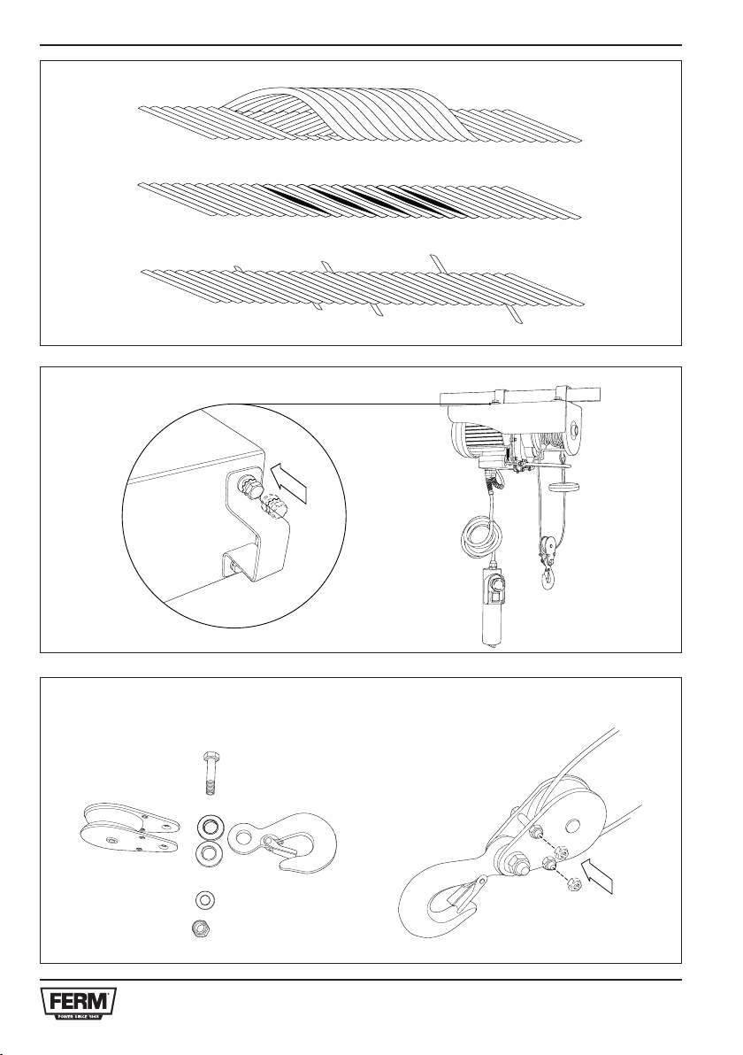
Fig. A
Fig. 3
Fig. 4
Fig. B
Fig. C Fig. 5
Page 4
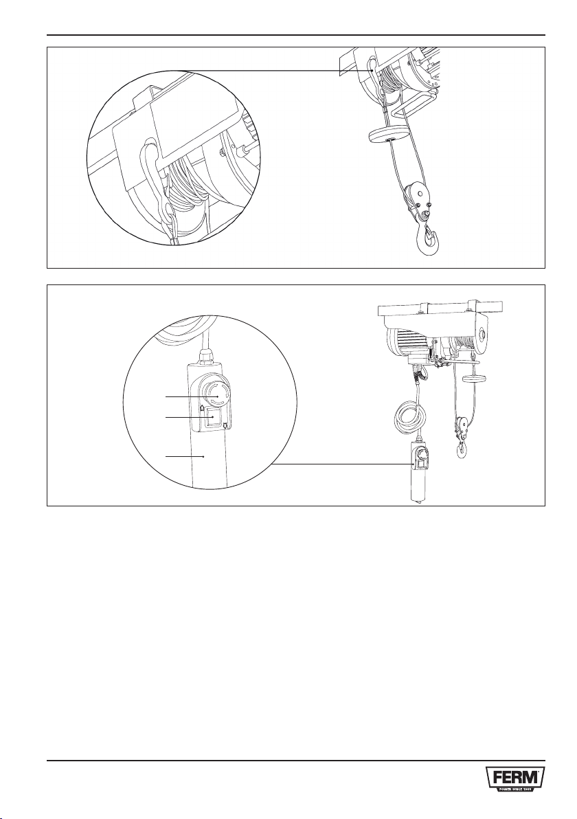
Fig. 6
Fig. 7
11
10
9
4
Page 5
ELECTRIC LEVER HOIST
The numbers in the following text correspond
with the pictures at page 2-4
EN
*S3 = intermittent operation.
During a period of 10 minutes, the machine may
run max. 20% (2.0 min.)
Read this operators guide carefully,
before using the machine. Ensure that
you know how the machine works, and
how it should be operated. Maintain the
machine in accordance with the
instructions, and make certain that the
machine functions correctly. Keep this
operator’s guide and other enclosed
documentation with the machine.
Intended use
The electric lever hoist is an ideal appliance in
your garage or shed for hoisting all kinds of loads.
Be aware: This machine is only for domestic use.
Improper use:
Do not use outside (tool is not weatherproof)
This machine cannot be used for the industry.
Do not hoist people or animals.
Contents
1. Machine data
2. Safety instructions
3. Installation
4. Use
5. Service & maintenance
1. Machine data
Technical specification
Voltage 230 V, 50 Hz
Input power 500 W
*Work rate S3 20% - 10 min
Rated load 125kg (without pulley)
250 kg (with pulley)
Lifting height 12m (without pulley)
6m (with pulley)
Lifting speed 8m/min (without pulley)
4m/min (with pulley)
Cable diameter 3.0 mm
Resister cable ≥ 1870 N/mm
Cable length 12 m
Weight 11.5 kg
Current 2.2 A
Insulation grade B
Protecting grade IP54
Group of mechanisms M1
Contents of packing
1 Electric lever hoist
1 Pulley + coupling
Brackets + bolts
1 Instruction manual
1 Safety instructions
1 Warranty card
Check the machinesk loose parts and accessories
for transport damage.
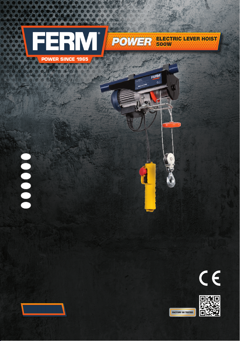
Features
Fig. 1
1. Bracket
2. Down limit pole
3. Lever automatic stop
4. Limit block
5. Drum
6. Steel cable
7. Hook
8. Mains cable
9. Remote control
10. Push button
11. (Emergency) stop button
12. Motor
2. Safety instructions
List of symbols
Danger of bodily injury or material
damage.
Keep bystanders at a distance.
Immediately unplug the plug from the
mains electricity in the case that the cord
2
gets damaged and during maintenance.
When using electric machines always observe the
safety regulations applicable in your country to
reduce the risk of fire, electric shock and personal
injury.
Read the following safety instructions and also the
enclosed safety instructions.
5
Page 6
EN
• Always check that the voltage corresponds to
the voltage on the rating plate. In case the
mains voltage is not suitable they should be
checked by a skilled electrician.
• Your socket plug must be grounded and your
electric system must be supplied with an earth
leakage circuit breaker.
• Keep children and other unauthorized
persons away from the machine.
• Protect the machine from frost and low
temperatures.
• In case the machine cannot hoist a load, do
not keep pressing the hoisting pushbutton, to
avoid damaging the machine. It means that
the load exceeds the machine maximum
capacity.
• The machine shall not be disassembled when
running or connected to power.
• The machine shall not be operated when it is
raining or storming.
Do not stand under hoisted weights!
• Before starting the work, make sure that the
steel cable is correctly winded around the reel
and the pitch is equal to the cable diameter
(Fig. 2).
Observe the maximum load indicated on
the hoist, not that on the hook!
• Do not lift loads bigger then the rated load of
the hoist.
• Leave at least three turns of cable around the
reel, so that the cable connection is not under
stress.
• If the red cable appears do not continue to
unroll it.
• To avoid any danger, do not wind more than
15 m of cable around the reel.
• In case the steel cable is worn out, it must be
replaced only with a cable of same features
manufactured by us. It can be found at all
authorized service shops.
• Before starting the work, check that switches
are in good operating conditions.
• In case the hoist stops during the lowering of
a load, it is normal that the load goes down a
few millimeters more because of the inertial
force.
• Never pull or push laterally the cable or the
load.
• Transport of people with the hoist is forbidden.
• Avoid switch-on / switch-off quickly
sequences.
• Wear gloves during transport.
Attention! The hoist electric motor is not
supplied with any mechanical overload
cut-out (to avoid an unexpected and
unwanted restart). Therefore, if you are
unable to hoist a load, do not insist and
let the motor cool down.
3. Installation
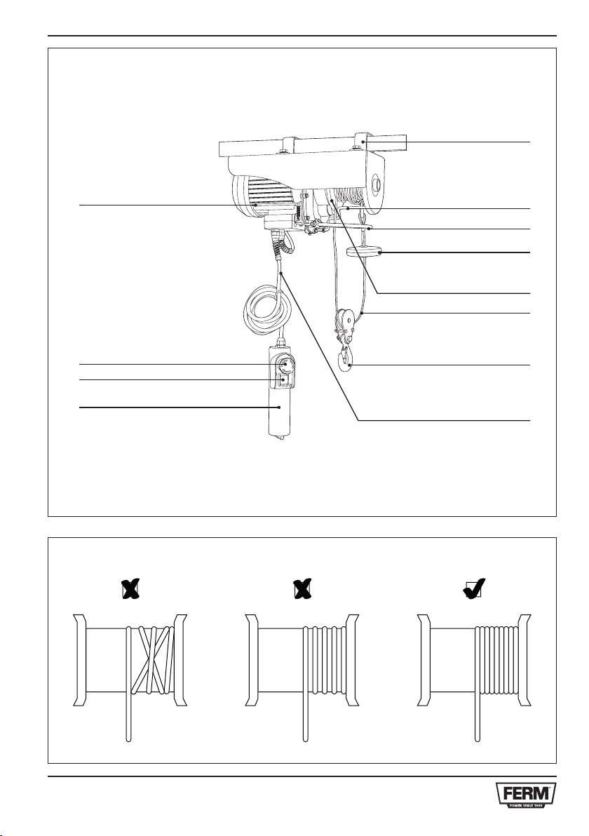
Mounting
Fig. 4
The hoist is provided with a bracket system which
allows holding rectangular beams. The beam
dimensions must be in accordance with the
distance between the hoist and the hinge and the
load to be hoisted. We recommend contacting
a skilled technician for help and checking the
solidity of the beam construction. The bolts must
be properly tightened. Before the start-up a skilled
technician should check that the support and the
coupling of the hoist are well sized.
Pulley block
Fig. 5 + 6
The lever hoist is provided with an extra pulley
and hook. When used correctly, the machine can
hoist double load. Assemble the pulley with help
of the bolts as shown in the picture. Tighten the
two bolts completely, and then unscrew them for
of turn.
The fixed hook on the machine can be attached
on the cover: there is a special hole for that
purpose. The load is now lifted with help of 2 steel
cables: the machine can hoist a double load.
4. Use
Remove the adhesive tape from the
cable reel before using the machine.
Secure the load carefully to the lever
hoist.
6
Page 7
Do not lift loads bigger then the rated
load of the hoist.
Start
Fig. 1 + 7
• Check if the (emergency) stop switch (11) is
not pressed. Turn the red stop switch
clockwise to engage.
• Press the push button ▲ (10) to lift the load.
• Press the push button ▼ (10) to lower the
load.
When the hoist is almost in top position, the limit
block (4) will move the lever (3) upwards. A switch
on the motor is now engaged and the motor will
stop running.
When the hoist is almost in low position (about
two turns of cable around the drum), the down
limit pole (2) will move. A switch on the motor is
now engaged and the motor will stop running.
Stop
When the push button (10) is not pressed, the
machine will stop. In case of an emergency,
immediately press the red stop switch (11) to
stop the machine. Operating the machine is not
possible when this red switch is pressed.
EN
1. The machine does not work when pressing
the push button.
• The electric cord is damaged or unplugged.
• Check the connections.
• The overload cut-out has tripped.
• Check the fuse box of your electric
system.
• During storage the brake sticks.
• Keep operating the push button for a
while until the brake releases.
2. The hoist cannot lift anymore.
• The electric motor is overheated.
• Let the motor cool down.
• The load exceeds the hoist capacity.
• Reduce the load to be lifted.
3. The brake does not operate; the load tends
to slip.
• Brake is worn out.
• Contact an authorized service centre to
repair the brake.
4. The steel cable is warped.
• See Fig. 3.
• Contact an authorized service centre to
replace the steel cable.
5. Service & maintenance
Always make sure that the machine is not
connected to the mains electricity when
you carry out any maintenance of the
mechanism.
Machines are designed to function for a long
time without any problems with a minimum of
maintenance. By cleaning the machine regularly
and using it in the correct way you can contribute
to a long life of your machine.
• Periodically check that the steel cable is in
good condition.
• Check that the screws securing the brackets
and pulley are well tightened.
• Periodically check that that stop switch and
push button panel are in good operating
conditions.
• For extraordinary maintenance contact an
authorized service center.
Troubleshooting
Repairs and servicing should only be
carried out by a qualified technician or
service firm.
Cleaning
Clean the machine housing regularly with a soft
cloth, preferably after each time you use the machine. Make sure that the ventilation slots are free
of dust and dirt. For stubborn dirt use a soft cloth
dampened with soapy water. Never use solvents
such as benzene, alcohol, ammonia, etc. These
types of solvents can damage the plastic parts.
Lubrication
The machine does not need any extra lubrication.
Faults
Should a fault occur, e.g. after wear of a part,
please contact the service address on the warranty
card. In the back of this manual you find an exploded view showing the parts that can be ordered.
Environment
To prevent damage during transport, the
7
Page 8
DE
appliance is delivered in a solid packaging which
consists largely of reusable material. Therefore
please make use of options for recycling the
packaging.
Faulty and/or discarded electrical or
electronic apparatus have to be collected
at the appropriate recycling locations.
Warranty
For the warranty conditions read the warranty
card at the back of these instructions for use.
Elektroseilwinde
Die Nummern im nachfolgenden Text
korrespondieren mit den Abbildungen auf
Seite 2-4.
Lesen Sie vor dem Gebrauch der
Maschine diese Bedienungsanleitung
aufmerksam durch. Machen Sie sich
unbedingt mit der Arbeitsweise der
Maschine und ihrer Bedienung vertraut.
Warten Sie die Maschine gemäß der
Anweisungen und stellen Sie sicher,
dass die Maschine einwandfrei arbeitet.
Bewahren Sie die Bedienungsanleitung
und andere zugehörige Unterlagen in
der Nähe der Maschine auf.
Verwendungszweck
Diese Elektroseilwinde ist ein ideales Hilfsmittel
zum Heben von Lasten in einer Garage oder
Werkstatt. Achtung: Das Gerät ist nur für den
Haugebrauch vorgesehen.
Verwendungsbeschränkungen:
• Das Gerät nicht im Freien verwenden (nicht
wetterfest).
• Das Gerät darf nicht zu industriellen Zwecken
eingesetzt werden.
Niemals Personen oder Tiere heben.
Inhalt
1. Gerätedaten
2. Sicherheitsvorschriften
3. Montage
4. Gebrauch
5. Wartung und Pflege
1. Gerätedaten
Technische Daten
Spannung 230 V, 50 Hz
Leistungsaufnahme 500 W
*Arbeitsquote S3 20% - 10 Min.
Nennlast 125 kg (ohne Seilrolle)
250 kg (mit Seilrolle)
Hubhöhe 12 m (ohne Seilrolle)
6 m (mit Seilrolle)
Seilgeschwindigkeit 8 m/min (ohne Seilrolle)
4 m/min (mit Seilrolle)
Seildurchmesser 3.0 mm
Widerstandskabel ≥ 1870 N/mm
8
2
Page 9
Kabellänge: 12 m
Gewicht 11.5 kg
Strom 2.2 A
Isolierklasse B
Schutzgrad IP54
Gruppe der Mechanismen M1
*S3 = Betrieb mit Unterbrechungen
Während eines Zeitraums von 10 Minuten darf
das Gerät maximal 20% (2.0 min.) laufen.
Lieferumfang
1 Elektroseilwinde
1 Seilrolle + Kupplung
Bügel + Schrauben
1 Bedienungsanleitung
1 Sicherheitsanleitung
1 Garantiekarte
Überprüfen Sie die Maschine, lose Teile und
Zubehör auf Transportschäden.
Merkmale
Abb. 1
1. Montageklammer
2. Begrenzungspfosten für Abwärtsbewegung
3. Hebel für automatischen Halt
4. Begrenzungsblock
5. Trommel
6. Stahlkabel
7. Haken
8. Netzkabel
9. Fernsteuerung
10. Druckknopf
11. (Not-) Aus-Knopf
12. Motor
DE
Halten Sie sich beim Gebrauch von
Elektrogeräten immer an die einschlägigen
Sicherheitsvorschriften Ihres Landes zur
Vorbeugung gegen Brand, elektrische Schläge
und Verletzungen. Lesen Sie sich die folgenden
Sicherheitsvorschriften sowie die beigefügte
Sicherheitsanleitung durch. Bewahren Sie diese
Vorschriften/Anleitung an einem sicheren Ort!
• Die Spannung muss mit den Angaben auf
dem Typenschild übereinstimmen. Bei einer
ungeeigneten Netzspannung muss ein
geschulter Elektriker zu Rate gezogen
werden.
• Die verwendete Steckdose muss geerdet sein
und die Elektroanlage muss mit einem FISchutzschalter ausgestattet sein.
• Halten Sie Kinder und andere Unbefugte von
der Winde Gerät fern.
• Das Gerät muss vor Frost und niedrigen
Temperaturen geschützt werden.
• Wenn die Winde eine Last nicht heben kann,
darf der Steuertaster nicht wiederholt betätigt
werden, da das Gerät dadurch beschädigt
werden kann. In diesem Fall überschreitet die
Last die maximale Traglast der Winde.
• Das Auseinanderbauen eines laufenden oder
an das Stromnetz angeschlossenen Geräts
ist nicht gestattet.
• Die Winde darf nicht bei Regen oder Unwetter
betrieben werden.
Nicht unter angehobenen Lasten stehen!
2. Sicherheitsvorschriften
Liste der Symbole
Gefahr von Verletzungen oder
Sachbeschädigung.
Zuschauer fernhalten.
Ziehen Sie, falls das Kabel beschädigt
wird und auch während
Wartungsarbeiten, sofort den
Netzstecker.
• Vor Arbeitsbeginn muss sichergestellt sein,
dass das Stahlseil ordnungsgemäß um die
Trommel gewickelt ist und dass der Abstand
dem Seildurchmesser entspricht (Abb. 2).
Gültig ist die auf der Winde angegebene
maximale Traglast, nicht die auf dem
Haken!
• Keine Lasten heben, die die Nennlast der
Winde übersteigen.
• Es müssen immer mindestens drei
Windungen an Zugseil auf der Trommel
verbleiben, damit die Seilbefestigung nicht zu
stark belastet wird.
• Wenn ein rotes Stück Seil sichtbar wird, darf
9
Page 10
DE
das Seil nicht weiter abgewickelt werden.
• Um Gefahrensituationen zu vermeiden,
dürfen nicht mehr als 15 m Seil um die
Trommel gewickelt werden.
• Wenn das Stahlkabel verschlissen ist, muss
es durch ein gleichwertiges, von uns
hergestelltes Seil ersetzt werden. Passende
Stahlseile sind bei jedem autorisierten
Servicegeschäft erhältlich.
• Vor Arbeitsbeginn müssen die Schalter auf
einwandfreie Funktion überprüft werden.
• Wenn die Winde beim Absenken einer Last
angehalten wird, sinkt die Last aufgrund der
Trägheitslast noch einige Millimeter weiter.
Das ist normal
• Das Seil oder die Last nie seitlich schieben
oder ziehen.
• Der Transport von Menschen mit der Winde
ist nicht gestattet.
• Schnell wechselndes Ein- und Ausschalten
vermeiden.
• Zum Transport des Geräts sind Handschuhe
zu tragen.
Achtung! Der Elektromotor der Winde ist
nicht mit einem mechanischen
Überlastschutz ausgestattet (um ein
unerwartetes/unerwünschtes erneutes
Anspringen zu verhindern). Machen Sie
daher nicht weiter, wenn eine Last nicht
gehoben werden kann, und lassen Sie
den Motor abkühlen.
3. Montage
Befestigung
Abb. 4
Zur Winde gehört ein Bügelsystem zur
Befestigung an rechteckigen Balken. Die
Balkenabmessungen müssen dem Abstand
zwischen Winde und Scharnier und der zu
hebenden Last entsprechen. Wir empfehlen,
einen geschulten Techniker zu Rate zu ziehen
und diesen die Stabilität der Balkenkonstruktion
beurteilen zu lassen. Die Schrauben müssen
fest angezogen werden. Vor der Inbetriebnahme
sollten die Dimensionierung der Stützkonstruktion
und der Windenkupplung von einem geschulten
Techniker überprüft werden.
Seilrolle
Abb. 5 + 6
Im Lieferumfang der Seilwinde sind eine
Zusatzseilrolle und ein zusätzlicher Haken
enthalten. Bei richtiger Nutzung kann das Gerät
eine doppelte Traglast bewältigen. Montieren
Sie die Seilrolle wie in der Abbildung dargestellt
mit Hilfe der Schrauben. Ziehen Sie die beiden
Schrauben so fest wie möglich an und lockern
Sie sie anschließend um eine Vierteldrehung.
Der feste Haken der Winde kann an dem dazu
vorgesehenen Loch in der Abdeckung befestigt
werden. Die Last wird nun von zwei Stahlseilen
2 getragen - die Winde kann eine doppelte Last
heben.
4. Gebrauch
Entfernen Sie vor Gebrauch des Geräts
das Klebeband von der Seiltrommel.
Die Last sorgfältig an der Winde
befestigen.
Keine Lasten heben, die die Nennlast der
Winde übersteigen.
Starten
Abb. 1 +7
• Sicherstellen, dass der (Not-) Aus-Schalter
(11) nicht eingedrückt ist. Den roten AusSchalter im Uhrzeigersinn drehen, bis er
einrastet.
• Zum Heben der Last den Drucktaster 5 (10)
betätigen.
• Zum Absenken der Last den Drucktaster 6
(10) betätigen.
Wenn die Winde sich fast in der obersten Stellung
befindet, bewirkt die Hubbegrenzung (4) eine
Aufwärtsbewegung des Hebels (3). Dadurch wird
ein Schalter auf dem Motor angesprochen, was
zum Anhalten des Motors führt.
Wenn das Hebezeug fast vollständig abgewickelt
ist (etwa zwei Seilschläge des Kabels um die
Trommel), wird der Begrenzungspfosten für
Abwärtsbewegung (2) in Bewegung versetzt. Nun
wird ein Motorschalter betätigt und der Motor hält
an.
Anhalten
Wenn der Drucktaster (10) nicht eingedrückt
ist, wird das Gerät angehalten. Betätigen Sie im
Notfall sofort den roten Aus-Schalter (11), um
10
Page 11

das Gerät anzuhalten. Wenn dieser rote Schalter
eingedrückt ist, kann die Winde nicht verwendet
werden.
5. Wartung und Pflege
DE
4 Das Stahlseil ist verdreht.
• Siehe Abb. 3
• Stahlseil von einem autorisierten
Servicezentrum auswechseln lassen.
Vergewissern Sie sich immer, dass das
Gerät nicht an das Netz angeschlossen
ist, wenn Sie Wartungsarbeiten an dem
Mechanismus vornehmen.
Geräte sind dafür ausgelegt, über einen langen
Zeitraum problemlos und mit minimaler Wartung
zu arbeiten. Durch regelmäßiges Reinigen des
Geräts und richtige Benutzung können Sie zu
einer langen Lebensdauer des Geräts beitragen.
• Das Stahlseil regelmäßig auf einwandfreien
Zustand überprüfen.
• Die Befestigungsschrauben der Bügel und
der Seilrolle auf festen Sitz überprüfen.
• Den Aus-Schalter und die Drucktaster
regelmäßig auf einwandfreie Funktion
überprüfen.
• Wenden Sie sich für außergewöhnliche
Wartungsarbeiten an ein autorisiertes
Servicezentrum.
Fehlerbehebung
1. Die Winde funktioniert bei Betätigung des
Drucktasters nicht.
• Das Stromkabel ist beschädigt oder steckt
nicht in der Steckdose.
• Anschlüsse überprüfen.
• Der Überlastschutz wurde ausgelöst.
• Sicherungskasten der Elektroanlage
überprüfen.
• Bremse hängen geblieben.
• Den Drucktaster mehrmals betätigen, bis
die Bremse sich löst.
2. Die Winde kann nichts mehr heben.
• Nach der Lagerung ist die Überlastung des
Elektromotors.
• Motor abkühlen lassen.
• Die Last übersteigt die maximale Traglast.
• Zu hebende Last reduzieren.
Lassen Sie Ihre Maschine nur von einem
qualifizierten Fachmann oder einer
qualifizierten Reparaturwerkstatt warten
und reparieren.
Reinigung
Reinigen Sie das Gerätegehäuse regelmäßig mit
einem weichen Tuch, vorzugsweise nach jeder
Benutzung. Vergewissern Sie sich, dass die
Belüftungsschlitze frei von Staub und Schmutz
sind. Entfernen Sie hartnäckigen Schmutz mit
einem weichen, mit Seifenwasser angefeuchteten
Tuch. Verwenden Sie niemals Lösungsmittel
wie Benzol, Alkohol, Ammoniak usw., da diese
Lösungsmittel die Kunststoffteile beschädigen
können.
Schmierung
Das Gerät erfordert keine zusätzliche
Schmierung.
Fehler
Sollte beispielsweise nach Abnutzung eines
Teils ein Fehler auftreten, dann setzen Sie sich
bitte mit der auf der Garantiekarte angegebenen
Serviceadresse in Verbindung. Im hinteren Teil
dieser Anleitung befindet sich eine ausführliche
Übersicht über die Teile, die bestellt werden
können.
Umwelt
Um Transportschäden zu verhindern, wird die
Maschine in einer soliden Verpackung geliefert.
Die Verpackung besteht weitgehend aus
verwertbarem Material. Benutzen Sie also die
Möglichkeit zum Recyclen der Verpackung.
Schadhafte und/oder entsorgte
elektrische oder elektronische Geräte
müssen an den dafür vorgesehenen
Recycling-Stellen abgegeben werden.
3. Die Bremse funktioniert nicht, die Last
rutscht ab.
• Verschlissene Bremse.
• Bremse von einem autorisierten
Servicezentrum reparieren lassen.
Garantie
Die Garantiebedingungen entnehmen Sie bitte
der Garantiekarte auf der Rückseite dieser
Gebrauchsanleitung.
11
Page 12

NL
ELEKTRISCHE KABELTAKEL
De nummers in de nu volgende tekst
verwijzen naar de afbeeldingen op pagina 2-4.
Lees deze handleiding zorgvuldig door
voor u de machine gebruikt. Zorg ervoor
dat u weet hoe de machine werkt en hoe
u deze moet bedienen. Onderhoud de
machine volgens de instructies en
verzeker u ervan dat de machine goed
werkt. Bewaar deze handleiding en
bijgesloten documentatie bij de machine.
Bedoeld gebruik
De elektrische kabeltakel is een ideaal apparaat
voor in garage of schuur voor het hijsen van
allerlei lasten. Let op: de machine is alleen
bedoeld voor huishoudelijk gebruik.
Oneigenlijk gebruik:
• Het apparaat niet in de vrije buitenlucht gebruiken (onbeschermd tegen weersinvloeden
• De machine is niet geschikt voor industrieel
gebruik
• Het is niet toegestaan om mensen of dieren te
takelen.
Inhoud
1. Machine gegevens
2. Veiligheidsinstructies
3. Installatie
4. Gebruik
5. Service & onderhoud
1. Machine gegevens
Technische specificatie
Voltage 230 V, 50 Hz
Motorvermogen 500 W
*Functiesnelheid S3 20% - 10 min
Hefvermogen 125 kg (zonder katrol)
250 kg (met katrol)
Hefhoogte 12 m (zonder katrol)
6 m (met katrol)
Hefsnelheid 8 m/min (zonder katrol)
4 m/min (met katrol)
Kabeldiameter 3.0 mm
Breuksterkte ≥ 1870 N/mm
Kabellengte 12 m
Gewicht 11.5 kg
Stroomsterkte 2.2 A
Isolatieklasse B
Beschermingsklasse IP54
Mechanisme-klasse M1
*S3 = afwisselende werking
Gedurende 10 minuten mag het apparaat
maximaal 20% (2.0 min.) in werking zijn.
Inhoud van de verpakking
1 Elektrische kabeltakel
1 Katrol + haak
Beugels + bouten
1 Gebruikershandleiding
1 Veiligheidsinstructies
1 Garantiekaart
Controleer de machine, losse onderdelen en
accessoires op transportschade.
Onderdelen
Fig. 1
1 Beugel
2. Voeler onderste begrenzingschakelaar
3. Schakelaar automatische stop
4. Begrenzingsblok
5. Kabeltrommel
6. Stalen kabel
7. Haak
8. Netkabel
9. Afstandsbediening
10. Drukschakelaar
11. (Nood)stopschakelaar
12. Motor
2. Veiligheidsinstructies
Symbolenlijst
Gevaar voor lichamelijk letsel of
materiële schade.
Houd omstanders op afstand.
Verwijder onmiddellijk de stekker uit het
stopcontact bij beschadiging van het
snoer en tijdens
2
onderhoudwerkzaamheden
Neem bij het gebruik van elektrische
machines altijd de plaatselijk geldende
veiligheidsvoorschriften in acht in verband met
12
Page 13

brandgevaar, gevaar voor elektrische schokken
en lichamelijk letsel. Lees behalve onderstaande
instructies ook de veiligheidsvoorschriften in de
apart bijgevoegde veiligheidskatern door. Bewaar
de instructies zorgvuldig!
• Controleer altijd of de netspanning
overeenkomt met de aangegeven spanning
op het typeplaatje. In het geval dat het voltage
niet overeenkomt, raadpleeg dan een
vakkundige elektricien.
• De wandcontactdoos dient geaard te zijn en
het elektrische circuit dient te zijn voorzien
van een aardlekschakelaar.
• Houd kinderen en onbevoegden verwijderd
van de machine.
• Bescherm de machine tegen vorst en lage
temperaturen.
• In het geval dat de machine een gewicht niet
kan takelen, forceer de machine dan niet door
de drukschakelaar ingedrukt te houden. Het
gewicht is dan groter dan het maximumbereik
van de machine.
• Schakel voor elk onderhoud de machine uit
en haal de stekker uit het stopcontact.
• Gebruik de machine niet bij regen of stormweer.
Blijf niet staan onder een opgetakeld
gewicht!
• Controleer voordat u begint te werken
zorgvuldig of de kabel zich correct om de
haspel bevindt. De windingen moeten precies
naast elkaar liggen (Fig.2).
Neem het maximumgewicht in acht dat is
aangegeven op de takel, niet het gewicht
op de haak!
NL
• Controleer de conditie van de schakelaars
voordat u met takelwerkzaamheden begint.
• Bij het laten zakken van het gewicht, als de
takel stilstaat, daalt het gewicht nog enkele
millimeters als gevolg van inertie.
• Trek of duw nooit in zijdelingse richting aan de
last.
• Het hijsen van personen met de takel is
verboden.
• Vermijd het snel achter elkaar aan- en
uitschakelen van de takel.
• Draag handschoenen tijdens transport.
Let op! De elektrische kabeltakel is niet
uitgerust met een mechanische
overbelastingsbeveiliging (om
ongewenst en onverwachte inschakeling
te voorkomen). Indien de machine er niet
in slaagt een gewicht op te takelen,
forceer ze dan niet maar laat de motor
afkoelen.
3. Installatie
Montage
Fig. 4
De kabeltakel is voorzien van beugels waarmee
de machine kan worden bevestigd aan een
rechthoekige balk. De afmetingen van de
draagbalk moeten zijn afgestemd op de
afstand tussen takel, katrol en de te hijsen last.
Aangeraden wordt om een gespecialiseerde
technicus te raadplegen voor advies en controle
van de stevigheid van de draagbalk constructie.
De bouten moeten goed worden vastgedraaid.
Laat voordat u de machine in gebruik neemt
door een gespecialiseerde technicus controleren
of de drager en katrol van de takel correct zijn
geïnstalleerd.
• Hijs geen grotere gewichten dan toegestaan
met de takel.
• Laat ten minste drie windingen op de haspel
om de kabelbevestiging niet onder druk te
zetten.
• Als de rode staalkabel verschijnt, laat de takel
dan niet verder zakken.
• Plaats nooit meer dan 15 m staalkabel op de
haspel om gevaarlijke situaties te voorkomen.
• Als de stalen kabel versleten is, laat hem dan
vervangen bij een erkende vakhandel met
een door ons geproduceerde kabel met
dezelfde eigenschappen.
Katrol
Fig. 5 + 6
The kabeltakel is voorzien van een extra katrol
met haak. Wanneer deze op correcte wijze
wordt gemonteerd, kan de kabeltakel tweemaal
het aangeven gewicht hijsen. Monteer de katrol
met behulp van de meegeleverde bouten zoals
weergeven in de afbeelding. Draai de twee bouten
helemaal vast en draai ze vervolgens een slag terug.
De aan de staalkabel voorgemonteerde haak kan
worden ingehaakt in het daarvoor bestemde gat
van de behuizing van de kabeltakel. De last wordt
in dit geval gehesen met behulp van 2 kabels: de
13
Page 14

NL
machine kan nu het dubbele gewicht hijsen.
4. Gebruik
Verwijder het plakband van de staalkabel
op de haspel alvorens de machine te
gebruiken.
Maak de last goed vast aan de
kabeltakel.
Hijs geen grotere gewichten dan
toegestaan met de takel.
Start
Fig. 1 + 7
• Controleer of de (nood) stop schakelaar (11)
niet is ingedrukt. Draai de rode knop met de
wijzers van de klok mee om te ontgrendelen.
• Bedien de drukschakelaar 5 (10) om te last te
hijsen.
• Bedien de drukschakelaar 6 (10) om de last te
laten zakken.
Als de takel bijna in hoogste positie is, duwt
de kunststof schijf (4) tegen de bediening
automatische stop (3). Een schakelaar op de
elektromotor wordt ingedrukt en de elektromotor
schakelt uit.
Als de takel bijna in de onderste positie is
(ongeveer twee slagen van de kabel rond de
trommel), wordt de voeler van de onderste
begrenzingschakelaar (2) bewogen. Hierdoor
wordt er een schakelaar op de motor omgezet
waardoor de motor wordt uitgeschakeld.
Stop
Wanneer de drukschakelaar (10) niet wordt
ingedrukt, zal de machine stoppen. In geval van
nood: druk meteen de rode stop schakelaar (11)
om de machine te stoppen. Het bedienen van
de machine is niet mogelijk wanneer deze rode
schakelaar is ingedrukt.
De machines zijn ontworpen om gedurende
lange tijd probleemloos te functioneren met een
minimum aan onderhoud. Door de machine
regelmatig te reinigen en op de juiste wijze te
behandelen, draagt u bij aan een hoge levensduur
van uw machine.
• Controleer regelmatig de staat van de
staalkabel.
• Controleer of de schroeven van de beugels
en katrol goed zijn vastgedraaid.
• Controleer regelmatig de werking van de
stop- en drukschakelaar.
Storingen
1. De machine werkt niet terwijl de
drukschakelaar wordt bediend.
• Het elektriciteitsnoer is beschadigd of niet
aangesloten.
• Controleer de aansluitingen.
• Een zekering is gesprongen.
• Controleer de zekeringen in de meterkast.
• Tijdens opslag is de rem blijven vastzitten.
• Blijf de drukknop gebruiken tot de
remmen loslaten.
2. De kabeltakel kan de last niet meer hijsen.
• De elektromotor is oververhit.
• Laat de elektromotor afkoelen.
• De last is zwaarder dan het bereik van de
kabeltakel.
• Verminder het gewicht van de te hijsen
last.
3. De rem werkt niet meer en de last dreigt te
zakken.
• De rem is versleten.
• Neem contact op met een
gespecialiseerde technicus om de rem te
repareren.
4. De staalkabel is vervormd.
• Zie Fig. 3
• Neem contact op met een
gespecialiseerde technicus om de
staalkabel te vervangen.
5. Service & onderhoud
Zorg dat de machine niet onder spanning
staat wanneer onderhoudswerkzaamheden aan het mechaniek worden
uitgevoerd.
14
Laat reparaties altijd uitvoeren door een
erkend installateur of reparatiebedrijf.
Reinigen
Reinig de machine-behuizing regelmatig met een
zachte doek, bij voorkeur iedere keer na gebruik.
Page 15

Zorg dat de ventilatiesleuven vrij van stof en
vuil zijn. Gebruik bij hardnekkig vuil een zachte
doek bevochtigd met zeepwater. Gebruik geen
oplosmiddelen als benzine, alcohol, ammonia,
etc. Dergelijke stoffen beschadigen de kunststof
onderdelen.
Smeren
De machine heeft geen extra smering nodig.
Storingen
Wanneer er zich een storing voordoet,
bijvoorbeeld bij slijtage van een onderdeel, neem
dan contact op met het onderhoudsadres op de
garantiekaart. Achter in deze handleiding ziet u
een opengewerkte afbeelding van de onderdelen
die besteld kunnen worden.
Milieu
Om transportbeschadiging te voorkomen, wordt
de machine in een stevige verpakking geleverd.
De verpakking is zo veel mogelijk gemaakt van
recyclebaar materiaal. Maak daarom gebruik van
de mogelijkheid om de verpakking te recyclen.
Defecte en/of afgedankte elektrische of
elektronische gereedschappen dienen
ter verwerking te worden aangeboden
aan een daarvoor verantwoordelijke
instantie.
Garantie
Lees voor de garantievoorwaarden de
garantiekaart achter in deze gebruiksaanwijzing.
FR
PALAN ÉLECTRIQUE À CÂBLE
Les chiffres du texte suivant correspondent
aux illustrations page 2-4.
Lisez attentivement ce guide de
l’opérateur avant d’utiliser la machine.
Assurez-vous que vous connaissez bien
le fonctionnement de la machine et son
maniement. Respectez les instructions
de la machine et soyez sûr que la
machine fonctionne correctement.
Laissez ce guide de l’opérateur et les
autres documents joints à proximité de la
machine.
Utilisation pour laquelle est prévue l’appareil
Le palan électrique à câble est l’aide idéale dans
votre garage ou votre remise pour soulever toutes
sortes de charges. Attention : cet appareil est
destiné à l’usage domestique exclusivement.
Utilisation abusive:
• N’utilisez pas l’appareil à l’extérieur (il ne
résiste pas aux intempéries).
• Cet appareil ne doit pas être utilisé pour
l’industrie.
• Ne jamais lever des personnes ou des
animaux.
Table des matières
1. Données de l’appareil
2. Instructions de sécurité
3. Installation
4. Utilisation
5. Entretien
1. Données de l’appareil
Spécifications techniques
Tension 230 V, 50 Hz
Alimentation 500 W
*Taux de travail S3 20 % - 10 min
Charge nominale 125 kg (sans poulie)
250 kg (avec poulie)
Hauteur de levage 12 m (sans poulie)
6 m (avec poulie)
Vitesse de levage 8 m/min (sans poulie)
4 m/min (avec poulie)
Diamètre du câble 3.0 mm
Câble de résistance ≥ 1870 N/mm
Longueur du câble 12 m
15
2
Page 16

FR
Poids 11,5 kg
Courant 2.2 A
Degré d’isolation B
Degré de protection IP54
Groupe de mécanisme M1
*S3 = fonctionnement intermittent
Sur une période de 10 minutes, la machine peut
fonctionner un maximum de 20 % (2.0 min.)
Contenu de l’emballage
1 Palan électrique à câble
1 Poulie et accouplement
Supports et boulons
1 Mode d’emploi
1 Instructions de sécurité
1 Carte de garantie
Vérifiez si la machine, les pièces détachées et
les accessoires n’ont pas été endommagés au
transport.
Composants
Fig. 1
1. Support
2. Barre de limite de descente
3. Levier d’arrêt automatique
4. Bloc de limite
5. Tambour
6. Câble en acier
7. Crochet
8. Cordon d’alimentation électrique
9. Commande à distance
10. Bouton poussoir
11. Bouton d’arrêt (d’urgence)
12. Moteur
2. Instructions de sécurité
Liste de symboles
Danger de blessure physique ou de
dommage matériel.
Lorsque vous utilisez des appareils électriques,
respectez toujours les règlements de sécurité
en vigueur dans votre pays, pour réduire le plus
possible les risques d’incendie, de choc électrique
et de blessures. Lisez bien les instructions de
sécurité qui suivent, ainsi que celles qui sont
inclues.
• Contrôlez toujours que la tension du réseau
correspond à la tension indiquée sur la
plaque. Si la tension du réseau ne correspond
pas, consultez un électricien qualifié.
• La prise doit être mise à la terre et le circuit
électrique doit être équipé d’un coupe-circuit
de fuite à la terre.
• Maintenez à distance de l’appareil les enfants
et toute personne non qualifiée.
• Protégez l’appareil du gel et des basses
températures.
• Lorsque l’appareil ne parvient pas à soulever
une charge, ne continuez pas à appuyer sur
le bouton de levage, pour ne pas
endommager l’appareil. Dans un tel cas, la
charge dépasse la capacité de l’appareil.
• L’appareil ne doit pas être démonté pendant
qu’il est en marche, ni pendant qu’il est
branché sur l’alimentation électrique.
• L’appareil ne doit jamais être mis en marche
sous la pluie ou durant un orage.
Ne vous tenez jamais sous une charge
suspendue !
• Avant de commencer le travail, assurez-vous
que le câble d’acier est enroulé correctement
sur le tambour, et que le pas d’enroulement
est égal au diamètre du câble (Fig. 2).
Respectez la charge maximale indiquée
sur le palan, et non celle sur le crochet !
Tenez des spectateurs à distance.
Débranchez immédiatement la fiche de
l’approvisdionnement électrique principal
dans le cas où la corde est endommagée
et pendant la maintenance.
16
• Ne tentez pas de lever des charges
dépassant la capacité nominale du palan.
• Laissez toujours au moins trois tours de câble
sur le tambour, pour ne pas mettre sous
tension le point d’attache du câble.
• Quand la partie rouge du câble devient
visible, cessez de le dérouler.
• N’enroulez jamais plus de 15 m de câble sur
le tambour, ceci serait dangereux.
Page 17

• Quand le câble d’acier est usé, il doit être
remplacé, et toujours avec un câble ayant les
mêmes spécifications, tel que nous le
fabriquons. Vous le trouverez chez tous les
services de maintenance reconnus.
• Avant de commencer à travailler, contrôlez
que les interrupteurs sont en bon état et
fonctionnent normalement.
• Lorsque le palan s’arrête pendant qu’une
charge descend, il est normal que la charge
continue de descendre de quelques
millimètres, sous l’effet de l’inertie.
• N’imprimez jamais de mouvement latéral au
câble ni à la charge, ni en tirant, ni en
poussant.
• Il est interdit de transporter des personnes sur
le palan.
• Évitez de mettre en marche et d’arrêter le
palan rapidement plusieurs fois de suite.
• Portez des gants de protection durant
l’utilisation.
Attention ! Le moteur électrique du palan
n’est pas équipé d’un mécanisme d’arrêt
automatique en cas de surcharge, pour
éviter les arrêts et redémarrages
intempestifs. Vous devez donc faire très
attention à ne pas insister quand le palan
ne parvient pas à lever une charge ;
laissez alors le moteur refroidir.
FR
Serrez à fond les deux boulons, puis desserrezles de de tour. Le crochet fixe de l’appareil se fixe
au couvercle : il y a un trou pratiqué à cet effet.
La charge est maintenant soulevée par 2 câbles
d’acer à la fois : l’appareil soulève une charge
double.
4. Utilisation
Enlevez la bande adhésive du tambour
du câble avant d’utiliser l’appareil.
Fixez avec soin la charge au palan.
Ne tentez pas de lever des charges
dépassant la capacité nominale du
palan.
Démarrage
Fig. 1 + 7
• Contrôlez que l’interrupteur d’arrêt d’urgence
(11) n’est pas enfoncé. Tournez le
commutateur d’arrêt rouge pour mettre le
contact.
• Appuyez sur le bouton 5 (10) pour lever la
charge.
• Appuyez sur le bouton 6 (10) pour descendre
la charge.
3. Installation
Montage
Fig. 4
Le palan est équipé d’un système de support
pour poutres rectangulaires. La dimension des
poutres doit correspondre à la distance entre le
palan et la charnière et la charge à lever. Nous
recommandons de faire appel à un technicien
spécialisé pour garantir la solidité de la poutraison
Les boulons doivent être serrés comme il faut.
Avant de démarrer le palan, il faut avoir fait
contrôler par un technicien qualifié que les
supports et la fixation du palan sont adéquats.
Bloc de la poulie
Fig. 5 + 6
Le palan à levier est équipé d’une poulie et
d’un crochet supplémentaires. Si vous l’utilisez
correctement, l’appareil est capable de lever une
charge double. Montez la poulie au moyen des
boulons, comme indiqué sur l’illustration.
Lorsque le palan est presque tout en haut, le bloc
limiteur (4) relève le levier (3). Ceci enclenche un
interrupteur sur le moteur, qui s’arrête.
Lorsque le treuil atteint presque la position
inférieure (environ deux boucles de câble
restantes sur le tambour), la barre de limite de
descente (2) se déplacera. Un interrupteur sur le
moteur est actionné et le moteur s’arrête.
Arrêt
Lorsque le bouton (10) n’est pas enfoncé,
l’appareil s’arrête. En cas d’urgence, enfoncez
immédiatement le commutateur d’arrêt rouge (11)
pour arrêter l’appareil. Tant que ce commutateur
rouge est enfoncé, l’appareil ne fonctionne pas.
5. Entretien
Veillez toujours à ce que la machine ne
soit pas branchée à l’électricité principale
si vous entretenez le mécanisme.
17
Page 18

FR
Les machines ont été conçues pour fonctionner
longtemps sans problème et avec un minimum
d’entretien. En nettoyant régulièrement et
correctement la machine, vous garantissez à
votre machine une longue durée de vie.
• Contrôlez régulièrement que le câble d’acier
est en bon état.
• Contrôlez que les vis maintenant les supports
et la poulie sont bien serrées.
• Contrôlez régulièrement que le commutateur
d’arrêt et le panneau des boutons de
commande sont en bon état.
• Pour tout entretien sortant de l’ordinaire,
contactez un centre d’entretien reconnu.
Problèmes
1. L’appareil ne se met pas en marche quand
vous appuyez sur le bouton.
• Le cordon d’alimentation est endommagé ou
n’est pas branché.
• Contrôlez les branchements.
• Le coupe-circuit de surcharge a été
déclenché.
• Contrôlez les fusibles de votre circuit
électrique.
• Le frein se bloque pendant le stockage.
• Continuez d’actionnez le bouton de mise
marche pendant un moment pour
débloquer le frein.
utilisation. Veillez à ce que les fentes d’aération
soient propres de poussière et de saletés.
En présence de saleté tenace, employez un
chiffon doux imbibé d’eau savonneuse. Proscrivez
l’emploi de solvants comme l’essence, l’alcool,
l’ammoniaque etc. car ces substances attaquent
les pièces en plastique.
Graissage
Cette machine ne nécessite pas de graissage
supplémentaire.
Dysfonctionnements
Veuillez vous adresser au centre de service indiqué sur la carte de garantie en cas d’un dysfonctionnement, par exemple après l’usure d’une
pièce. Vous trouverez, à la fin de ce manuel, un
schéma avec toutes les pièces que vous pouvez
commander.
Environnement
Pour éviter les dommages liés au transport, la
machine est livré dans un emballage robuste.
L’emballage est autant que possible constitué
de matériau recyclable. Veuillez par conséquent
destiner cet emballage au recyclage.
Tout équipement électronique ou
électrique défectueux dont vous seriez
débarrassé doit être déposé aux points
de recyclage appropriés.
2. Le palan ne parvient plus à lever la charge.
• Le moteur électrique est surchauffé.
• Laissez le moteur se refroidir.
• La charge dépasse la capacité du palan.
• Diminuez la charge.
3. Le frein ne fonctionne pas, la charge
glisse.
• Le frein est usé.
• Faites appel à un service d’entretien
reconnu.
4. L’appareil ne se met pas en marche quand
vous appuyez sur le bouton.
• Voir la Fig. 3
• Faites appel à un service d’entretien
recon nu pour faire remplacer le câble
d’acier.
Nettoyage
Nettoyez régulièrement le boîtier au moyen
d’un chiffon doux, de préférence après chaque
18
Garantie
Pour les conditions de garantie, lisez le certificat
de garantie joint à part.
Page 19

POLIPASTO ELÉCTRICO DE
PALANCA
Los números indicados en el texto siguiente
coresponden a las ilustraciones de la página
2- 4.
Lea esta guía del operador
detenidamente antes de utilizar la
máquina. Asegúrese de conocer el
funcionamiento de la máquina y cómo
debe operarse. Mantenga la máquina
según las instrucciones y asegúrese de
que funciona correctamente. Mantenga
con la máquina esta guía del operador y
el resto de la documentación incluida.
Uso previsto
El polipasto eléctrico de palanca es un aparato
ideal para tener en el garaje o en el cobertizo
ya que sirve para izar toda clase de cargas.
Tenga cuidado: Esta máquina está concebida
únicamente para uso doméstico.
Resistencia del cable ≥ 1870 N/mm
Longitud del cable 12 m
Peso 11.5 kg
Corriente 2.2A
Nivel de aislamiento B
Grado de protección IP54
Grupo de mecanismos M1
*S3 = funcionamiento intermitente
Durante un periodo de 10 minutos, la máquina
puede operar a un máximo de 20% (2.0 min.)
Contenido del embalaje
1 Polipasto eléctrico de palanca
1 Polea y acoplamiento
Abrazaderas + pernos
1 Manual de instrucciones
1 Normas de seguridad
1 Tarjeta de garantía
Revise la máquina, las piezas sueltas y los
accesorios asegurándose de que no hayan
sufrido daños durante el transporte.
ES
2
Uso inadecuado:
• No utilizar en el exterior (la herramienta no es
resistente a la intemperie).
• Esta máquina no puede usarse para
aplicaciones industriales.
• No utilice el aparato para elevar animales ni
personas.
Contenido
1. Información sobre el aparato
2. Normas de seguridad
3. Instalación
4. Uso
5. Servicio y mantenimiento
1. Información sobre el aparato
Especificaciones técnicas
Voltaje 230 V, 50 Hz
Potencia de entrada 500 W
*Coeficiente de operación S3 20% - 10 min.
Carga máxima admisible 125 kg (sin polea)
250 kg (con polea)
Altura de elevación 12 m (sin polea)
6 m (con polea)
Velocidad de elevación 8 m/min (sin polea)
4 m/min (con polea)
Diámetro del cable 3.0 mm
Componentes
Fig. 1
1. Abrazadera
2. Poste de límite de descenso
3. Palanca de parada automática
4. Tope
5. Tambor
6. Cable de acero
7. Gancho
8. Cable de corriente
9. Mando a distancia
10. Pulsador
11. Interruptor de parada (emergencia)
12. Motor
2. Normas de seguridad
Lista de símbolos
Peligro de lesiones físicas o daños en el
material.
Mantenga a la gente alejada de la zona
de trabajo.
Desenchufe la clavija inmediatamente de
la corriente en caso de que el cable sufra
19
Page 20

ES
daños y durante la reparación
Al hacer uso de aparatos eléctricos cíñase
siempre a las normas de seguridad aplicables
en su país a fin de reducir el riesgo de incendios,
choques eléctricos y lesiones personales.
Lea las siguientes recomendaciones de
seguridad y las instrucciones de seguridad
adjuntas. ¡Mantenga estas instrucciones en un
lugar seguro!
• Verifique siempre que el voltaje de la fuente
de alimentación corresponda al voltaje
indicado en la placa. Si el voltaje de la red no
es el adecuado, hágalo revisar por un
electricista cualificado.
• El conector macho debe tener conexión a
tierra y el sistema eléctrico debe estar
provisto de un cortacircuito de fuga a tierra.
• Mantenga a los niños y a otras personas no
autorizadas alejadas de la máquina.
• Proteja la máquina contra las heladas y las
bajas temperaturas.
• Si la máquina no puede levantar una carga,
no continúe presionando el pulsador de izado,
así evitará daños a la máquina. La razón del
no funcionamiento adecuado es que la carga
excede la capacidad máxima de la máquina.
• No debe desensamblar la máquina mientras
esté en funcionamiento o conectada a la
fuente de alimentación.
• No debe poner en marcha la máquina cuando
llueva o haya tormenta.
¡No se pare debajo de la carga izada!
• Antes de empezar a trabajar asegúrese de
que el cable de acero está correctamente
enrollado alrededor del carrete y que el paso
sea igual al diámetro del cable (Fig. 2).
¡Cíñase a la carga máxima indicada en el
elevador, no en el gancho!
• No ice cargas superiores a la carga máxima
admisible del polipasto.
• Deje al menos tres vueltas de cable alrededor
del carrete a fin de no ejercer tensión en el
punto de fijación del cable.
• No desenrolle el cable más allá de la marca
roja.
• Para evitar cualquier peligro, no enrolle más
de 15 metros de cable alrededor del carrete.
• Sustituya el cable desgastado únicamente
por un cable con las mismas características
fabricado por nosotros. Este se consigue en
todos los centros de servicio autorizados.
• Antes de empezar a trabajar, verifique que los
interruptores están en buenas condiciones de
funcionamiento.
• Cuando el polipasto se detiene al descender
una carga, es normal que ésta descienda
unos cuantos milímetros más debido a la
fuerza de inercia.
• Nunca tire ni empuje lateralmente el cable o
la carga.
• Está prohibido el transporte de personas con
el elevador.
• Evite encender y apagar la máquina en
intervalos sucesivos cortos.
• Use guantes durante el transporte.
¡Atención! El motor eléctrico del
polipasto no viene equipado con ningún
dispositivo mecánico de corte de
sobrecarga (esto con el fin de evitar que
la máquina se ponga en marcha en
forma inesperada o indeseada). Por lo
tanto, si no le es posible izar una carga,
no insista y deje enfriar primero el motor.
3. Instalación
Montaje
Fig. 4
El polipasto está provisto de un sistema de
abrazaderas que permite sostener vigas
rectangulares. Las dimensiones de la viga deben
corresponder con la distancia entre el polipasto y
la articulación y la carga a izar. Le recomendamos
que contacte a un electricista cualificado para
que le asista y compruebe la solidez de la
construcción de la viga. Los pernos deben estar
debidamente apretados. Antes de la puesta en
marcha, un técnico cualificado debe comprobar
que el soporte y el acople del polipasto son del
tamaño adecuado.
Bloque de poleas
Fig. 5 + 6
El polipasto viene equipado con una polea y un
gancho adicionales. Si se usa correctamente,
la máquina puede izar una carga doble. Instale
20
Page 21

la polea con la ayuda de los pernos tal como se
indica en la ilustración. Apriete los dos pernos
completamente y, a continuación, aflójelos de
vuelta. El gancho fijo a la máquina se puede
acoplar a la cubierta; hay un orificio especial para
este fin. Ahora, la carga será izada con la ayuda
de 2 cables de acero; es decir, la máquina puede
izar una carga doble.
4. Uso
Retire la cinta adhesiva del carrete del
cable antes de usar la máquina.
ES
5. Servicio y mantenimiento
Asegúrese siempre de que la
herramienta no esté conectada a la
fuente de electricidad cuando realice el
mantenimiento de la herramienta.
Las herramientas se han diseñado para que
funcionen por un gran periodo de tiempo sin
problemas con un mantenimiento mínimo. Si se
limpia de forma regular la herramienta y se utiliza
de la forma adecuada, se contribuye a una vida
mayor de la herramienta.
Asegure la carga cuidadosamente al
polipasto.
No ice cargas superiores a la carga
máxima admisible del polipasto.
Puesta en marcha
Fig. 1 +7
• Verifique que el interruptor de parada (de
emergencia) (11) no esté pulsado. Gire el
interruptor de parada rojo en el sentido de las
agujas del reloj para engranar.
• Presione el botón pulsador 5 (10) para izar la
carga.
• Presione el botón pulsador 6 (10) para
descender la carga.
Cuando el elevador está casi en la posición de
tope, el bloque de límite (4) mueve la palanca (3)
hacia arriba. De esta forma un interruptor engrana
el motor y éste deja de funcionar.
Cuando el polipasto se encuentre
aproximadamente en la posición más baja (unas
dos vueltas de cable en el tambor), el poste de
límite de descenso (2) se moverá. El conmutador
del motor se accionará y el motor se detendrá.
Parada
Al soltar el botón pulsador (10) la máquina deja
de funcionar. En caso de emergencia, pulse
inmediamente el interruptor de parada rojo (11)
para detener el funcionamiento de la máquina.
Mientras el interruptor rojo esté pulsado no será
posible poner en marcha la máquina.
• Revise periódicamente que el cable de acero
esté en buenas condiciones.
• Verifique que los tornillos que aseguran las
abrazaderas y la polea estén bien apretados.
• Revise periódicamente que el interruptor de
parada y el botón pulsador estén en buenas
condiciones de funcionamiento.
• Para mantenimiento adicional póngase en
contacto con un centro de servicio autorizado.
Resolución de problemas
1. La máquina no se pone en funcionamiento
al pulsar el botón.
• El cable eléctrico está malo o no está
conectado.
• Revise las conexiones.
• El dispositivo de corte de sobrecarga está
desconectado.
• Revise la caja de fusibles de su sistema
eléctrico.
• Durante el almacenamiento la abrazadera se
ha pegado.
• Sostenga pulsado el botón durante un
momento hasta que despegue la
abrazadera.
2. El polipasto ya no levanta.
• El motor eléctrico está recalentado.
• Deje enfriar el motor.
• La carga excede la capacidad del polipasto.
• Reduzca la carga a izar.
•
3. El freno no funciona; la carga tiende a
deslizarse.
• Véase la Fig. 3.
• Contacte a un centro de servicio
autorizado para reparar el freno.
21
Page 22

HU
4. El cable de acero está deformado.
• El freno está gastado.
• Contacte a un centro de servicio
autorizado para sustituir el cable de
acero.
Limpieza
Limpie la carcasa de la herramienta de forma
regular con un paño suave, después de cada uso.
Asegúrese de que las ranuras de ventilación no
estén obstruidas con polvo o suciedad. En caso
de suciedad muy resistente, utilice un paño suave
humedecido con agua y jabón. Nunca utilice
disolventes como benzol, alcohol, amoniaco, etc.,
ya que estas sustancias pueden dañar las piezas de
plástico.
Lubricación
La herramienta no necesita una lubricación extra.
Averías
Si se presenta una avería, por ejemplo, por el
desgaste de una pieza, póngase en contacto con
el proveedor de servicios indicado en la tarjeta de
garantía. En el dorso de este manual encontrará
un amplio resumen de las partes de recambio que
se pueden ordenar.
2–4. oldal ábráira hivatkoznak.
Agéphasználatelőttvassaelalaposan
eztakezelésiútmutatót.Győződjön
meg arról, hogy ismeri a gép
működését,éshelyeshasználatát.Az
útmutatásoknakmegfelelőentartsa
karbanagépet,ésellenőrizze,hogya
megfelelőenműködik-e.Tartsaezta
kezelőiútmutatótésatöbbimellékelt
dokumentumot a gép közelében.
Az elektromos emelő ideális eszköznek bizonyul
a garázsában vagy fészerében mindenféle teher
felemeléséhez.
Tartsa szem előtt: Ez a gép kizárólag házi
használatra készült.
Helytelen használat:
Ne használja a szabadban (ez a gép nem
időjárásálló)
Iparszerű felhasználásra nem alkalmas.
Embereket vagy állatokat ne emeljen vele.
Uso ecológico
Para prevenir los daños durante el transporte, el
aparato ha sido embalado. Dicho embalaje está
hecho, en la medida de lo posible, de material
reciclable. Le rogamos, por lo tanto, que recicle
dicho material.
Cualquier aparato eléctrico o electrónico
desechado y/o defectuoso tiene que
depositarse en los lugares apropiados
para ello.
Garantía
Las condiciones de la garantía de pueden leer en
la tarjeta de garantía que se adjunta en la parte
posterior de estas instrucciones.
22
Tartalom
1. A gép adatai
2. Biztonsági útmutatások
3. A gép üzembe helyezése
4. A gép kezelése
5. Gondozás és karbantartás
1. A GÉP ADATAI
Feszültség 230 V, 50 Hz
Felvett teljesítmény 500 W
*Folyamatos üzemidő S3 20% – 10 perc
Névleges teherbírás 125 kg (nélkül csiga)
250 kg (a csiga)
Emelőmagasság 12 m (nélkül csiga)
6 m (a csiga)
Emelési sebesség 8 m/perc (nélkül csiga)
4 m/perc (a csiga)
Kábel átmérője 3,0 mm
Kábel húzószilárdsága ≥ 1870 N/mm2
Kábel hossza 12 m
Súly 11,5 kg
Áramerősség 2,2 A
Page 23

Szigetelés B osztály
Védelmi osztály IP54
Hajtóműosztály M1
*S3 = szakaszos üzemeltetés.
10 perces időtartamon belül annak
legfeljebb 20%-ában (2,0 perc) működtethető
folyamatosan
A csomag tartalma
1 Elektromos emelő Ā
1 Csiga + csatlakozókarmantyú Konzolok +
csavarok
1 Használati útmutató
1 Biztonsági útmutató
1 Garanciakártya
Ellenőrizze a gépet, annak részeit és tartozékait,
hogy nem sérültek-e meg szállítás közben.
A gép részei
1. ábra
1. Konzol
2. Alsó határoló oszlop
3. Emelő automatikus ütközője
4. Határoló blokk
5. Dob
6. Acélkábel
7. Kampó
8. Tápkábel
9. Távirányító
10. Nyomógomb
11. (Vész)leállító gomb
12. Motor
HU
előírásokat, hogy csökkentse a tűz, áramütés és
személyi sérülések veszélyét.
Olvassa el a következő biztonsági útmutatót a
géphez mellékelt biztonsági útmutatóval együtt.
• Mindig ellenőrizze, hogy a hálózat feszültsége
megfelel-e a gép adattábláján feltüntetett
feszültségnek. Ha a hálózati feszültség nem
megfelelő, kérje képzett villanyszerelő
segítségét.
• A konnektornak földeltnek kell lennie, és az
elektromos hálózatot földelési szivárgóáram
érzékelős megszakítóval kell ellátni.
• A gyermekeket és más illetéktelen
személyeket tartsa távol a géptől.
• Fagytól és alacsony hőmérséklettől óvja a
gépet.
• Ha a gép nem képes egy terhet felemelni, ne
tartsa lenyomva a gombot, hogy a gép ne
sérüljön. Ez annyit jelent, hogy a teher
meghaladja a gép emelőkapacitását.
• Tilos a gépet szétszerelni, amíg mozgásban
vagy áram alatt van.
• Esős vagy viharos időjárásnál tilos
üzemeltetni.
Ne álljon felemelt teher alá!
• Az emelés megkezdése előtt bizonyosodjon
meg arról, hogy az acélkábel megfelelően fel
van csévélve a dobra, és hogy az osztás
megegyezik a kábel átmérőjével (2. ábra).
2. BIZTONSÁGI ÚTMUTATÓ
A szimbólumok jelentése
Személyi sérülés vagy anyagi kár
veszélye.
Tartsa az arra járókat biztonságos
távolságban.
Karbantartáselőtt,illetveatápkábel
sérülése esetén azonnal húzza ki a gép
dugaszát a konnektorból.
Elektromos gépek használata során mindig
tartsa be az országában érvényes munkavédelmi
A legnagyobb megengedett teherbírás
az, amelyik a gépen van feltüntetve, nem
pedig az, amelyik a kampón látható!
• Ne emeljen az emelő névleges teherbírását
meghaladó súlyú terhet.
• Hagyjon a dobon legalább három fordulatra
való kábelt, hogy a kábelcsatlakozó ne
feszüljön.
• Ha megjelenik a kábel pirosra színezett része,
ne csévélje le a kábelt annál tovább.
• A veszély megelőzése végett 15 m-nél
hosszabb kábelt ne csévéljen az orsóra.
• Ha már elhasználódott az acélkábel, általunk
gyártott, ugyanolyan jellemzőkkel rendelkező
új kábelre kell cserélni. Ez minden
márkakereskedőnél beszerezhető.
• Mielőtt hozzákezdene az emeléshez,
ellenőrizze, hogy jó állapotban vannak-e a
23
Page 24

HU
kapcsolók.
• Ha az emelő a teher leengedése közben leáll,
természetes, hogy a teher a tehetetlenségi
erő miatt még néhány milliméterrel lejjebb
ereszkedik.
• Soha ne húzza és ne tolja a kábelt vagy a
terhet oldalirányba.
• Tilos az emelőn embereket szállítani.
• Ne kapcsolgassa be és ki túl gyors
egymásutánban.
• A gép szállítása közben viseljen kesztyűt.
Figyelem!Azemelővillanymotorjanincs
ellátva mechanikus túlterhelés elleni
védelemmel (hogy kerülje a váratlan és
véletlen újraindulást). Ezért, ha egy
terhet nem képes felemelni, ne
próbálkozzon tovább, hanem hagyja a
motortlehűlni.
3. A GÉP ÜZEMBE HELYEZÉSE
Szerelés
4. ábra
Az emelő konzolrendszerrel van ellátva, így
négyszög-keresztmetszetű tartók felemelésére
is képes. A tartók méreteinek meg kell felelniük
az emelő, a csuklópánt és a felemelendő teher
közötti távolságnak. Javasoljuk, hogy kérje
képzett szakember segítségét a tartó szerkezeti
szilárdságának ellenőrzéséhez. A csavarokat
erősen meg kell húzni. Az emelés előtt képzett
szakembernek kell ellenőriznie, hogy az emelő
támasztéka és a csatlakozás jól van-e méretezve.
Csigasor
5. + 6. ábra
Az emelő extra csigával és kampóval van
felszerelve. Helyes használat esetén a gép
képes kettős teher felemelésére. Szerelje fel a
csigát a csavarokkal az ábra szerint. Húzza meg
teljesen a két csavart, majd lazítsa meg őket a
kicsavaráshoz.
A gépre rögzített kampó a burkolathoz
erősíthető: van egy erre kijelölt furat. A terhet
most 2 acélkábellel emeli fel: a gép kettős teher
felemelésére képes.
4. A GÉP KEZELÉSE
Agéphasználataelőttvegyelea
ragasztócsíkot a kábeldobról.
Gond os an er ősítseat er hetaze me lőhöz.
Neemeljenazemelőnévleges
teherbírását meghaladó súlyú terhet.
Indítás
1. + 7. ábra
• Ellenőrizze, nincs-e lenyomva a (vész)leállító
kapcsoló (11). Fordítsa a piros leállító
kapcsolót az óramutató járásának irányába,
hogy bekapcsoljon.
• Nyomja meg a ▲ gombot (10) a teher
felemeléséhez.
• Nyomja meg a ▼ gombot (10) a teher
leengedéséhez.
Amikor az emelő majdnem a legfelső helyzetében
van, a határoló blokk (4) a kart (3) felfelé mozdítja.
A motoron lévő kapcsoló ekkor bekapcsol, és a
motor leáll.
Amikor az emelő majdnem a legalsó helyzetében
van (kb. két fordulatra való kábel van a dobon), az
alsó határoló oszlop (2) elmozdul. A motoron lévő
kapcsoló ekkor bekapcsol, és a motor leáll.
Leállítás
Amikor a nyomógomb (10) nincs lenyomva, a
gép leáll. Vészhelyzetben azonnal nyomja le a
piros leállító kapcsolót (11) a gép leállításához.
Amikor a piros kapcsoló le van nyomva, a gép
nem működik.
5. GONDOZÁS ÉS
Mielőttagépszerkezetének
karbantartásához kezd, bizonyosodjon
meg arról, hogy a dugasz ki van húzva a
konnektorból.
A gépeket úgy terveztük, hogy minimális
karbantartás mellett is hosszú ideig
problémamentesen használhatók legyenek. A
rendszeres tisztítással és helyes használattal
hozzásegíti a gépet ahhoz, hogy az hosszú
élettartamú legyen.
• Rendszeres időközökben ellenőrizze az
acélkábel állapotát.
• Ellenőrizze, hogy a konzolokat tartó csavarok
és a csiga jól meg vannak-e húzva.
24
Page 25

• Rendszeres időközökben ellenőrizze, hogy a
leállító kapcsoló és a nyomógomb panelje jó
állapotban vannak-e.
• Rendkívüli karbantartást márkaszervizzel
végeztessen.
Hibaelhárítás
1. A nyomógomb lenyomott állapotában a gép
• A tápkábel sérült vagy ki van húzva a
konnektorból.
• Ellenőrizze a csatlakozásokat.
• A túlterhelés elleni védelem kikapcsolta a
gépet.
• Ellenőrizze a hálózat biztosítékdobozát.
• Tárolás közben beragadt a fék.
• Működtesse tovább a nyomógombot, amíg a
fék ki nem old.
HU
Hibák
Meghibásodás esetén (pl. ha elkopik egy
alkatrész), lépjen kapcsolatba a szervizzel,
amelynek címét a garanciakártyán találja.
Kézikönyvünk végén találja a megrendelhető
alkatrészek robbantott ábráit.
Környezetvédelem
A szállítás közbeni sérülések megelőzése céljából
a gépet alaposan becsomagoltuk. A csomagolás
főleg újrahasznosítható anyagokból áll. Ezért
kérjük, tegye lehetővé a csomagolóanyagok
újrahasznosítását.
A hibás és/vagy kiselejtezett elektromos
vagy elektronikus készülékeket juttassa
elakijelöltbegyűjtőhelyekre
újrahasznosítás céljából.
• A villanymotor túlmelegedett.
• Hagyjaamotortlehűlni.
• A teher meghaladja az emelő kapacitását.
• Csökkentse a felemelni kívánt terhet.
hajlamos.
• Elhasználódott a fék.
• Márkaszervizzel javíttassa meg a féket.
4. Az acélkábel meggörbült.
• Lásd a 3. ábrát.
• Márkaszervizzel cseréltesse ki az
acélkábelt.
Javításokat és szervizelést csak képzett
szakember vagy cég végezhet.
A gép tisztítása
Rendszeresen, lehetőleg minden egyes használat
után törölje át a gép burkolatát puha ronggyal.
Ügyeljen arra, hogy a szellőzőnyílások portól és
szennyeződéstől mentesek legyenek. A makacs
szennyeződést szappanos vízben megnedvesített
puha ronggyal távolítsa el. Soha ne tisztítsa
oldószerekkel (például benzin, alkohol, ammónia
oldat stb.). Ezek az árthatnak a műanyag
részeknek.
Garancia
A garanciális feltételeket ennek a használati
útmutatónak a végén találja.
Kenés
A gép nem igényel külön kenést.
25
Page 26

262728
Page 27

Page 28

Page 29

DECLARATION OF CONFORMITY
LHM1011 ELECTRIC LEVER HOIST
(EN) We declare under our sole responsibility that this product is in conformity with
directive 2011/65/EU of the European parliament and of the council of 9 June on the
restriction of the use of certain hazardous substances in electrical and electronic
equipment is in conformity and accordance with the following standards and
regulations:
(DE) Der Hersteller erklärt eigenverantwortlich, dass dieses Produkt der Direktive
2011/65/EU des Europäischen Parlaments und des Rats vom 8. Juni 2011 über die
Einschränkung der Anwendung von bestimmten gefährlichen Stoffen in elektrischen
und elektronischen Geräten entspricht. den folgenden Standards und Vorschriften
entspricht:
(NL) Wij verklaren onder onze volledige verantwoordelijk heid dat dit product voldoet aan
de conform Richtlijn 2011/65/EU van het Europees Parlement en de Raad van 8 juni
2011 betreffende beperking van het gebruik van bepaalde gevaarlijke stoffen in
elektrische en elektronische apparatuur en in overeenstem ming is met de volgende
standaarden en reguleringen:
(FR) N ous déclarons sous notre seule responsabilité que ce produit est conforme aux
standards et directives suivants: est conforme à la Directive 2011/65/EU du
Parlement Européen et du Conseil du 8 juin 2011 concernant la limitation d’usage de
certaines substances dangereuses dans l’équipement électrique et électronique.
(ES) Declaramos bajo nuestra exclusiva responsabilidad que este producto cumple con
las siguientes normas y estándares de funcionamiento: se encuentra conforme con
la Directiva 2011/65/UE del Parlamento Europeo y del Consejo de 8 de junio de 2011
sobre la restricción del uso de determinadas sustancias peligrosas en los equipos
eléctricos y electrónicos.
(PT) Declaramos por nossa total responsabilida-de que este produto está em
conformidade e cumpre as normas e regulamentações que se seguem: está em
conformidade com a Directiva 2011/65/EU do Parlamento Europeu e com o
Conselho de 8 de Junho de 2011 no que respeita à restrição de utilização de
determinadas substâncias perigosas existentes em equipamento eléctrico e
electrónico.
(IT) Dichiariamo, sotto la nostra responsabilità, che questo prodotto è conforme alle
normative e ai regolamenti seguenti: è conforme alla Direttiva 2011/65/UE del
Parlamento Europeo e del Consiglio dell’8 giugno 2011 sulla limitazione dell’uso di
determinate sostanze pericolose nelle apparecchiature elettriche ed elettroniche.
(SV) Vi garanterar på eget ansvar att denna produkt upp fyller och följer följande
standarder och bestämmelser: uppfyller direktiv 2011/65/EU från Europeiska
parlamentet och EG-rådet från den 8 juni 2011 om begränsningen av användning av
farliga substanser i elektrisk och elektronisk utrustning.
(FI) Vakuutamme yksinomaan omalla vastuullamme, että tämä tuote täyttää seuraavat
standardit ja säädökset: täyttää Euroopan parlamentin ja neuvoston 8. kesäkuuta
2011 päivätyn direktiivin 2011/65/EU vaatimukset koskien vaarallisten aineiden
käytön rajoitusta sähkö- ja elektronisissa laitteissa.
(NO) Vi erklærer under vårt eget ansvar at dette produktet er i samsvar med følgende
standarder og regler: er i samsvar med EU-direktivet 2011/65/EU fra Europaparlamentet og Europa-rådet, pr. 8 juni 2011, om begrensning i bruken av visse
farlige stoffer i elektrisk og elektronisk utstyr.
(DA) Vi erklærer under eget ansvar, at dette produkt er i overensstemmelse med følgende
standarder og bestemmelser: er i overensstemmelse med direktiv 2011/65/EU fra
Europa-Parlamentet og Rådet af 8. juni 2011 om begrænsning af anvendelsen af
visse farlige stoffer i elektrisk og elektronisk udstyr.
(HU) Felelősségünk teljes tudatában kijelentjük, hogy ez a termék teljes mértékben
megfelel az alábbi szabványoknak és előírásoknak: je v souladu se směrnicí
2011/65/EU Evropského parlamentu a Rady EU ze dne 8. června 2011, která se týká
omezení použití určitých nebezpečných látek v elektrických a elektronických
zařízeních.
(CZ) N a naši vlastní zodpovědnost prohlašujeme, že je tento výrobek v souladu s
následujícími standardy a normami: Je v súlade s normou 2011/65/EÚ Európskeho
parlamentu a Rady z 8. júna 2011 týkajúcej sa obmedzenia používania určitých
nebezpečných látok v elektrickom a elektronickom vybavení.
(SK) Vyhlasujeme na našu výhradnú zodpovednosť, že tento výrobok je v zhode a súlade
s nasledujúcimi normami a predpismi: Je v súlade s normou 2011/65/EÚ Európske
ho parlamentu a Rady z 8. júna 2011 týkajúcej sa obmedzenia používania určitých
nebezpečných látok v elektrickom a elektronickom vybavení.
(SL) S polno odgovornostjo izjavljamo, da je ta izdelek v skladu in da odgovarja nasledn
jim standardom terpredpisom: je v skladu z direktivo 2011/65/EU Evropskega parla-
menta in Sveta z dne 8. junij 2011 o omejevanju uporabe določenih nevarnih snovi v
električni in elektronski opremi.
(PL) Deklarujemy na własną odpowiedzialność, że ten produkt spełnia wymogi zawarte w
następujących normach i przepisach: jest zgodny z Dyrektywą 2001/65/UE Parla
mentu Europejskiego i Rady z dnia 8 czerwca 2011 r. w sprawie ograniczenia stosowania niektórych niebezpiecznych substancji w sprzęcie elektrycznym i elektronicznym.
(LT) Prisiimdami visą atsakomybę deklaruojame, kad šis gaminys atitinka žemiau
paminėtus standartus arba nuostatus: atitinka 2011 m. birželio 8 d. Europos
Parlamento ir Tarybos direktyvą 2011/65/EB dėl tam tikrų pavojingų medžiagų
naudojimo elektros ir elektroninėje įrangoje apribojimo.
(LV) Ir atbilstoša Eiropas Parlamenta un Padomes 2011. gada 8. jūnija Direktīvai
2011/65/ES par dažu bīstamu vielu izmantošanas ierobežošanu elektriskās un
elektroniskās iekārtās.
(ET) Apgalvojam ar visu atbildību, ka šis produkts ir saskaņā un atbilst sekojošiem stand
artiem un nolikumiem: ir atbilstoša Eiropas Parlamenta un Padomes 2011. gada 8.
jūnija Direktīvai 2011/65/ES par dažu bīstamu vielu izmantošanas ierobežošanu
elektriskās un elektroniskās iekārtās.
(RO) Declarăm prin aceasta cu răspunderea deplină că produsul acesta este în
conformitate cu următoarele standarde sau directive: este în conformitate cu
Directiva 2011/65/UE a Parlamentului European şi a Consiliului din 8 iunie 2011 cu
privire la interzicerea utilizării anumitor substanţe periculoase la echipamentele
electrice şi electronice.
(HR) Izjavljujemo pod vlastitom odgovornoĻśu da je strojem ukladan sa slijedeśim
standardima ili standardiziranim dokumentima i u skladu sa odredbama: usklađeno s
Direktivom 2011/65/EU europskog parlamenta i vijeća izdanom 8. lipnja 2011. o
ograničenju korištenja određenih opasnih tvari u električnoj i elektroničkoj opremi.
(SRL) Pod punom odgovornošću izjavljujemo da je usaglašen sa sledećim standardima ili
normama: usaglašen sa direktivom 2011/65/EU Evropskog parlamenta i Saveta od
8.juna.2011. godine za restrikciju upotrebe određenih opasnih materija u električnoj i
elektronskoj opremi.
(RU) Под свою ответственность заявляем, что данное изделие соответствует
следующим стандартам и нормам: соответствует требованиям Директивы
2011/65/EU Европейского парламента и совета от 8 июня 2011 г. по
ограничению использования определенных опасных веществ в электрическом
и электронном оборудовании
(UK) На свою власну відповідальність заявляємо, що дане обладнання відповідає
наступним стандартам і нормативам: задовольняє вимоги Директиви 2011/65/
ЄС Європейського Парламенту та Ради від 8 червня 2011 року на обмеження
використання деяких небезпечних речовин в електричному та електронному
обладнанні.
(EL) ¢ЛПТУФ˘МВ ˘В‡ı˘У· fiЩИ ЩФ ЪФ˚fiУ ·˘Щfi Ы˘МКˆУВ› О·И ЩЛЪВ› ЩФ˘˜ ·Ъ·О¿Щˆ
О·УФУИЫМФ‡˜ О·И ЪfiЩ˘·: συμμορφώνεται με την Οδηγία 2011/65/ΕΕ του Ευρωπαϊκού
Κοινοβουλίου και του Συμβουλίου της 8ης Ιουνίου 2011 για τον περιορισμό της χρήσης
ορισμένων επικίνδυνων ουσιών σε ηλεκτρικό και ηλεκτρονικό εξοπλισμό
-
-
-
-
EN14492-2, EN55014-1, EN55014-2, EN60204-32, EN610003-2, EN61000-3-3
2006/42/EC, 2004/108/EC, 2011/65/EU, 2002/96/EC, 2006/95/EC
Zwolle, 01-10-2013 W. Dekens
CEO Ferm B.V.
It is our policy to continuously improve our products and we therefore reserve the right to change the
product specification without prior notice.
29
Page 30

Spare parts list
No. Description Position
400462 Mounting bracket screws set 3(X4) + 4(x2)
409740 Mounting bracket 2
400461 Key for cable 6
400463 Cable+hook 9 TILL 13
400464 Endstop bracket 14 + 16
400471 Down limit pole complete 15
806203 Bearing 6203 zz 19
806201 Bearing 6201 zz 24
400466 Motor cover 38
400465 Cooling fan 39
400467 Connection box (new model) 40 TILL 46 + 48 TILL 50
400460 Moving pulley with hook 51 TILL 54
400459 Switch 55
400468 Remote control 55 TILL 58 + 47
400469 Capacitor 14.5 +3 uF 58
30
Page 31

Exploded view
31
Page 32

www.ferm.com
1310-09
 Loading...