


BASS AMPLIFIER
RUMBLE STAGE 800
RUMBLE STUDIO 40
EXPANDED OWNER’S MANUAL
REV. A

CONTENTS
Introduction 1
Control Panel 2
Rear Panel 3
Safety Note: Speaker Cables 4
Thermal Performance and Protection 4
Presets
Preset Basics 5
Organizing Presets 6
Editing and Saving Presets 10
Editing Preset Amplier Control Knob Settings 13
Replacing Preset Amplier Models 15
Amplier and Cabinet Models 16
Editing Eects 18
Editing Eects Settings 26
Eects Types 29
Menu Functions 33
Setlists 34
WiFi Use 38
Bluetooth Use 41
Built-in Tuner 43
Auxiliary and Headphone Jacks 44
USB Connectivity 44
Line Out and FX Send/Return 44
Footswitch Use 45
MGT-4 Footswitch 45
Looper 49
EXP-1 Expression Pedal 53
Amp Settings 57
Global EQ 58
Cloud Presets 59
About This Amp 60
Firmware Updates and Factory Restore 61
Fender Tone™ App 63
Specications 64
INTRODUCTION
This expanded owner’s manual is a thorough user’s guide of the features and functions of the Rumble Studio
40 and Rumble Stage 800 ampliers.
As a complement to the Quick Start Guide that comes with each amplier, this manual presents a deeper,
more detailed look at Rumble Studio 40/Stage 800’s many versatile capabilities. This includes navigation and
modication of the many onboard presets, and comprehensive descriptions of the amplier and eect models. It also includes step-by-step and fully illustrated instructions for using Rumble Studio 40/Stage 800’s Setlist, WiFi, Bluetooth, USB, onboard tuner, EXP-1 Expression Pedal, MGT-4 Footswitch and looping functions.
Rumble Studio 40 and Rumble Stage 800 tonal possibilities are virtually endless, especially when paired with
the Fender Tone™ app. Be sure to check back regularly for rmware updates that improve and enhance the
Rumble bass experience (see page 61). While this expanded manual presents the most current version of the
ampliers, also check back for updated manual versions that will serve as even more helpful guides as the
Rumble family grows and evolves.
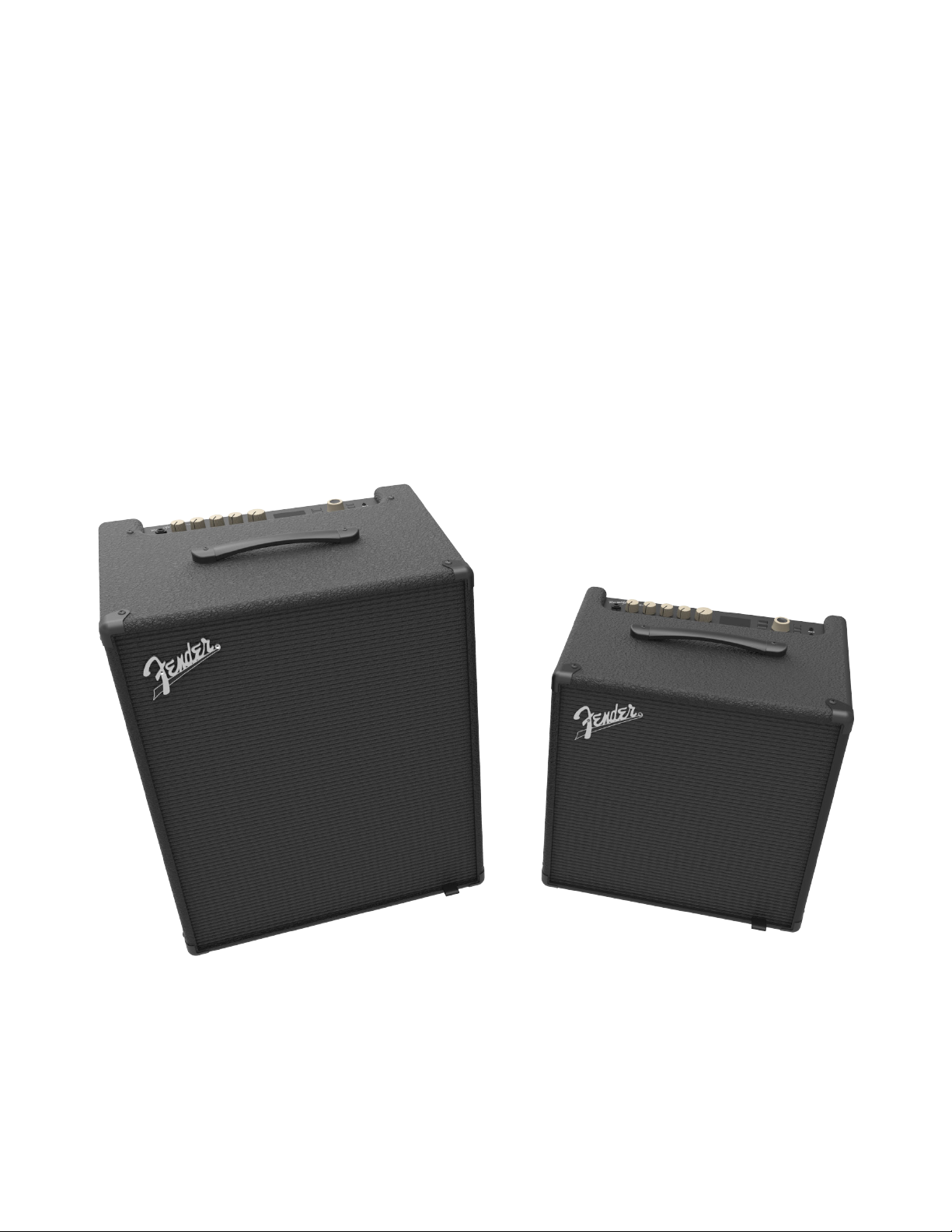
Rumble Stage 800 (left) and Rumble Studio 40 (right).
1
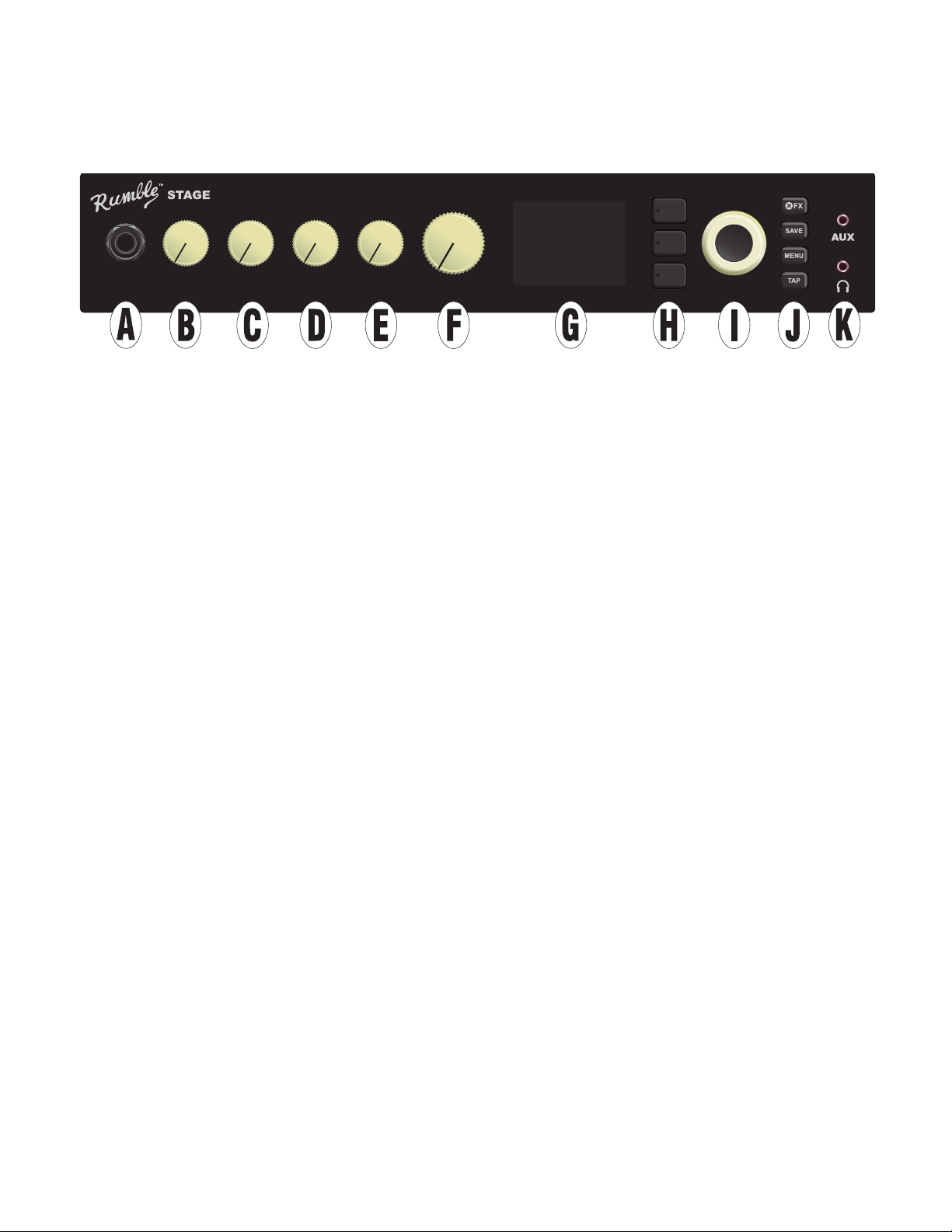
CONTROL PANEL
The Rumble Studio 40/Stage 800 top control panel consists of an instrument input, ve control knobs, a DISPLAY WINDOW, three LAYER pushbuttons, an ENCODER wheel, four UTILITY pushbuttons, an auxiliary input
(1/8”) and a headphone output (1/8”).
800
INPUT GAIN BASS TREBLEMIDDLE MASTER
A. INPUT: Plug instrument in here.
B. GAIN: Programmable control knob (see page 3) that aects gain setting in each preset.
C. BASS: Programmable control knob that aects bass tone setting in each preset.
D. MIDDLE: Programmable control knob that aects midrange tone setting in each preset.
E. TREBLE: Programmable control knob that aects treble tone setting in each preset.
F. MASTER VOLUME: The only non-programmable knob; controls actual overall output level to the speak-
er(s) and headphone jack.
G. DISPLAY WINDOW: Shows preset in use and all its contents and parameters, amplier and eects
menus, and other functions (i.e., tuner, menu functions, etc.).
H. LAYER BUTTONS
PRESET LAYER: Highlights preset layer, where presets are chosen.
SIGNAL PATH LAYER: Highlights signal path in each preset, where amp models, eects types and order
of eects can be modied.
CONTROLS LAYER: Highlights controls layer, where control knob settings can be modied (except Master Volume).
I. ENCODER: Multipurpose rotary control with press-switch function. For viewing, selecting and adjusting
Rumble Studio 40/Stage 800 presets, controls and other functions.
J. UTILITY BUTTONS
X FX: Bypasses all eects.
SAVE: For saving preset modications and new presets.
MENU: For accessing WiFi, Bluetooth, Tuner, Global EQ, cloud presets and other functions (see page 33).
TAP: For setting delay times and modulation rate settings; hold to access built-in tuner.
K. AUXILIARY INPUT, HEADPHONE OUTPUT: 1/8” auxiliary input for connecting external audio devices,
and 1/8” output for headphone use. Headphone output disables internal speaker(s).
2
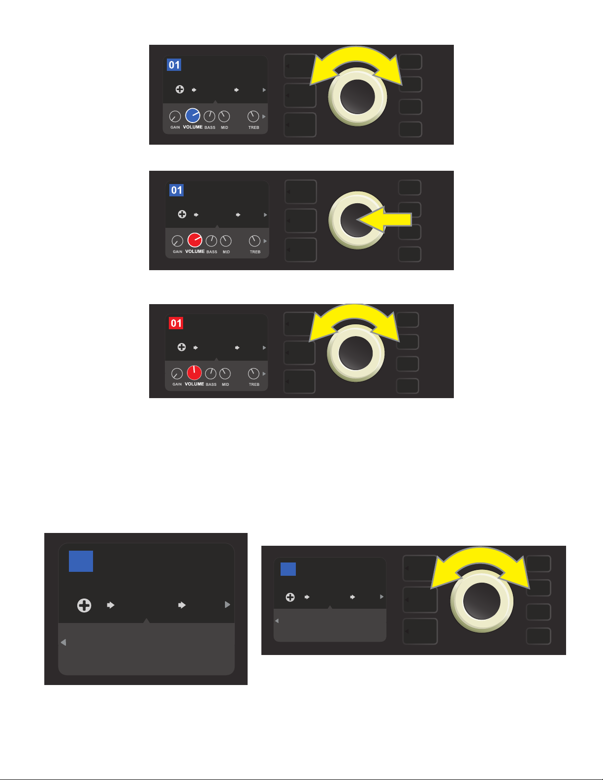
It’s important to note that all top control panel knobs except Master Volume (H) are, as described above,
800
“programmable.” That means that when a preset is rst selected, the physical position of a top control panel
knob may not indicate the actual setting contained in that preset (the actual setting appears in the display
window). Only the Master Volume control is not programmable—its physical position always indicates actual
overall volume. Once a programmable top control panel knob is turned, however, it and its digital counterpart within a preset become synchronized to the same value, as illustrated here:
Rumble V2 Clean
RUMBLE
V2
1494
Hz
GAIN BASS TREBLEMIDDLE MASTER
FREQ
Also note that an adjusted control knob setting can be saved in a new preset, or the original preset can be
overridden with the adjusted control knob setting. If the adjusted setting is not saved, the preset will revert
to its pre-programmed control knob settings when returning to the preset after leaving it, or when turning
the amplier o and back on again (see further info under “Editing and Saving Presets,” pages 10-13).
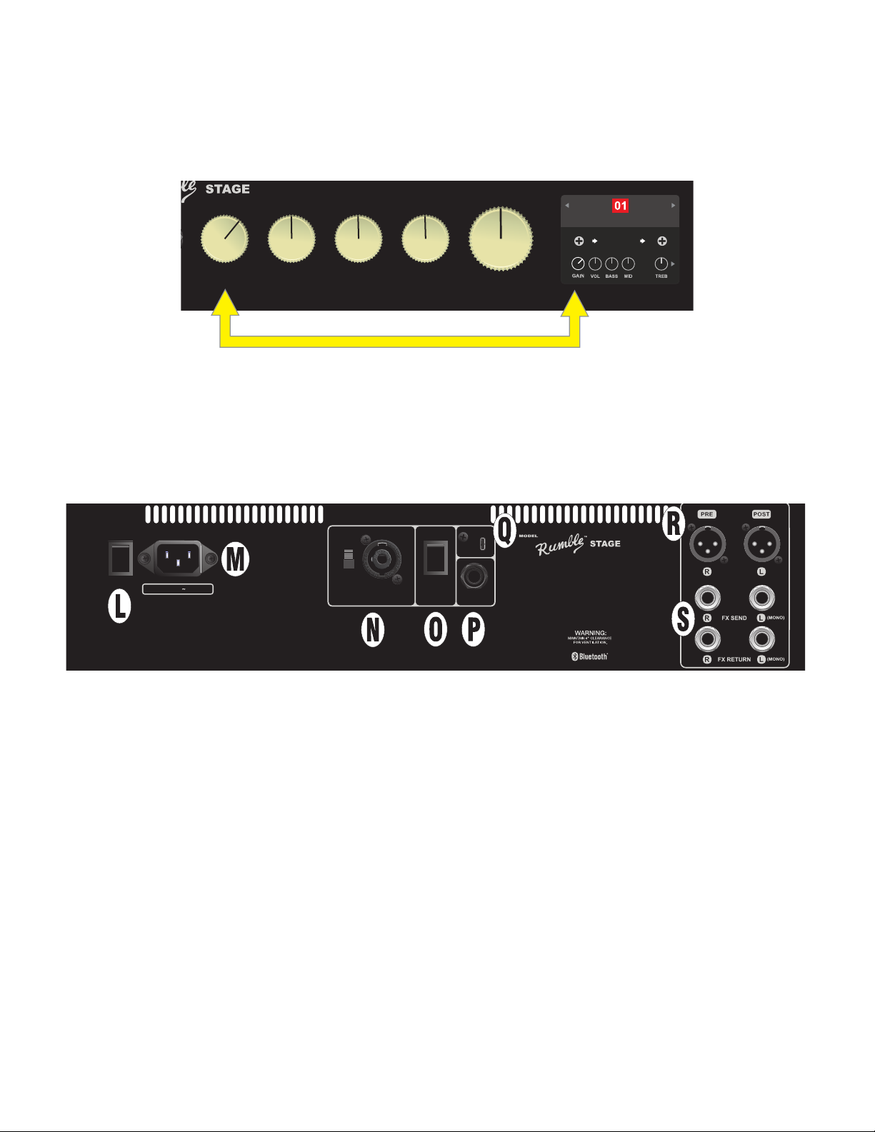
REAR PANEL
MONO
POWER INPUT POWER
ON
OFF
100-240VAC 50/60Hz
1500W
USE 8Ω IF NO
EXT. SPKR
400W
8Ω MIN
500W
4Ω MIN
)
SET SWITCH TO MATCH
EXT. SPKR IMPEDANCE
OFF
ON
USB
A PRODUCT OF:
FENDER MUSICAL INSTRUMENTS CORP.,
311 CESSNA CIRCLE CORONA, CA 92880 U.S.A.
FTSWHORNEXT. SPKR
MADE IN CHINA
TYPE PR: 5134
CONTAINS FCC ID: XQW-FMAPR5133
IC: 8690A-FMAPR5133
THIS PRODUCT IS COVERED BY THE FOLLOWING PATENT:
PATENT # 6,222,110
800
(
Rumble Stage 800 rear panel shown; Rumble Studio 40 rear panel has same features except for external speaker output and impedance switch (N).
L. POWER: Turns amplier on and o. When rst switched on, Rumble Studio 40 and Rumble Stage 800
both have a typical start-up-sequence time of 15 seconds before the rst preset appears in the DISPLAY
WINDOW (G).
For Rumble Stage 800 only, when quickly turning the power o and then on again (as during a WiFi update), a brief delay can occur during which the DISPLAY WINDOW will remain blank for 20-30 seconds.
This is normal in some high-powered ampliers such as this one, and the startup sequence will resume
with no need to cycle the power switch again.
M. IEC POWER INLET: Using the included power cord, connect to a grounded outlet in accordance with the
INPUT POWER voltage and frequency specied at the power inlet.
LINE OUT
STEREO
LINE OUT
N. EXTERNAL SPEAKER OUTPUT AND IMPEDANCE SWITCH (RUMBLE STAGE ONLY): Connect an exter-
nal speaker cabinet here (8Ω or 4Ω minimum impedance); combination jack works with Speakon® or 1/4”
speaker cable. Set switch to match impedance rating of external cabinet; continuous power rating of
external cabinet must meet or exceed power rating listed for the chosen switch setting. Set switch to 8Ω
when no external cabinet is connected.
O. HORN SWITCH: Turns high-frequency horn on and o.
3
P. FOOTSWITCH: Connect four-button MGT-4 footswitch or EXP-1 Expression Pedal here.
Q. USB PORT: Amp connection point for USB audio recording.
R. LINE OUT: Balanced line outputs for connection to external recording and sound reinforcement equipment.
The line out default setting is PRE/POST (mono), but can be congured as right/left stereo (post) outputs.
S. FX SEND/RETURN: Right/left send and return for stereo external eects use. Eects added here are “glob-
al” (not preset-specic) and act as the last elements in the signal path. Use left channel for mono eects.
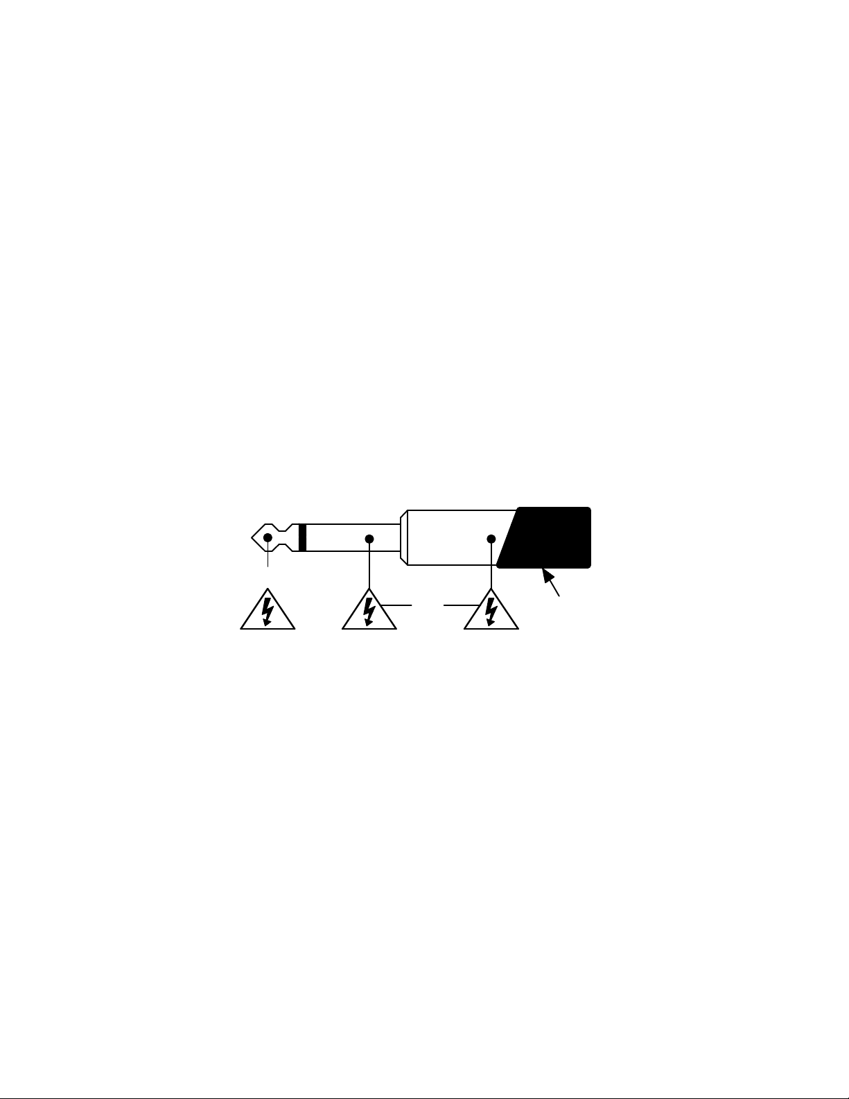
SAFETY NOTE: SPEAKER CABLES
The Rumble Stage 800 amplier’s high-power class “D” amplier operates in bridge mode, meaning that
voltage is present in both terminals (+) and (-). Use caution when connecting a speaker cable to the External
Speaker output on the rear panel—never let the tip (+) or sleeve (-) of a speaker cable (see illustration below)
contact the amp’s metal chassis or any other earth-grounded electrical equipment (i.e., audio mixers and
other sound reinforcement devices). A speaker cable plugged into the amp’s External Speaker output should
be connected only to another speaker cabinet.
Use caution when connecting 1/4” speaker cables with non-insulated (bare metal) plugs—always make speaker cable connections with the amp’s power turned o.
( + )
( - )
Insulation
THERMAL PERFORMANCE AND PROTECTION
Rumble Studio 40 and Rumble Stage 800 use class-D power ampliers with thermal and short circuit protection. In the event of a short circuit, the amplier will temporarily mute (no sound from speakers) and resume
normal operation when the fault is removed.
For increased thermal performance, Rumble Stage 800 has variable-speed fan cooling that starts at low speed
and increases as amplier temperature rises with playing use.
Leave at least 6” clearance between the amplier vents and other objects. If the amplier vents are blocked
or if the amp is used in an extremely hot environment, the amp may overheat and trigger thermal protection,
causing temporary speaker muting. Normal operation will automatically resume after the temperature cools
to a level within operating range.
Under the most severe operating conditions, the amp can overheat to the point of interrupting power, resulting in a blank DISPLAY WINDOW (G) and no sound from the speakers. In this unlikely event, normal operation
will automatically resume after the temperature cools to a level within operating range. Rumble Studio 40
may require the POWER switch (L) to be turned o and back on again after such a power interruption.
4
PRESET BASICS
Rumble Studio 40/Stage 800 comes with 100 sequentially numbered presets, and users can create and add
even more. Each preset has three “layers” that appear in the DISPLAY WINDOW. These are the PRESET LAYER (top), SIGNAL PATH LAYER (middle) and CONTROLS LAYER (bottom); the three LAYER BUTTONS provide
access to each layer (see illustration below).
PRESET LAYER
SIGNAL PATH LAYER
CONTROLS LAYER
LAYER BUTTONS
Press to select corresponding layer
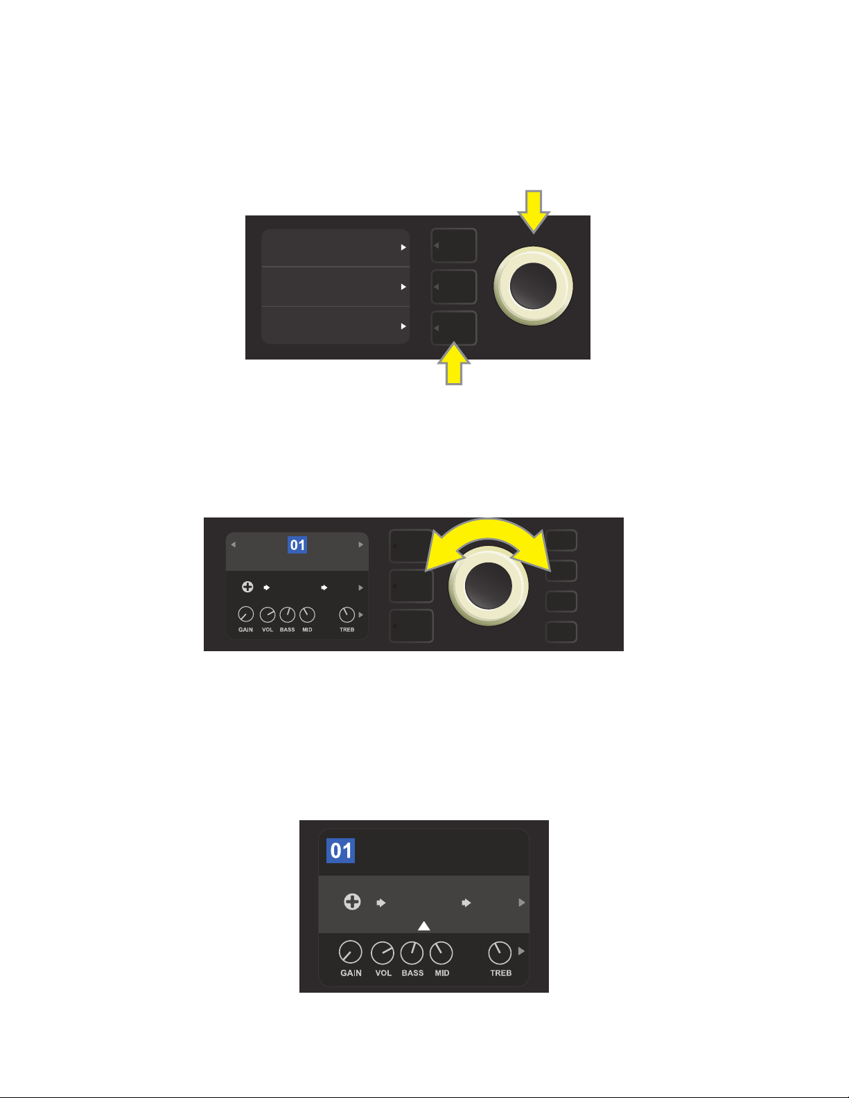
The PRESET LAYER is active when the amplier is rst turned on (on startup, Rumble Studio 40/Stage 800
loads the last preset used). To scroll through presets, turn the ENCODER (see illustration below); whichever
preset is displayed becomes active. Presets can also be selected by footswitch (see pages 48-49).
ENCODER
BASIC BASSMAN CLN
SUPER
BMAN-OD
1000
FREQ
SMALL
ROOM
The rst preset (01) is shown here in the PRESET LAYER.
The SIGNAL PATH LAYER of each preset consists of one of Rumble Studio 40/Stage 800’s many amplier models, and one or more of dozens of eects and their order (or no eects in some cases). The amp model appears
in the center of the SIGNAL PATH LAYER display. Eects appear in slots to either side of the amp model, representing their position in the signal path—“pre” to the left (placed “before” the amp) or “post” to the right of
the amp model (as in an eects loop). Select any of these items by turning the ENCODER; the selected item in
the SIGNAL PATH LAYER will have a white indicator arrow below it and text describing its position above it (see
illustration below).
BASIC BASSMAN CL
AMPLIFIER
SUPER
BMAN-OD
1000
FREQ
SMALL
ROOM
The amp model within the preset is selected here in the SIGNAL PATH LAYER, as indicated by the white arrow
and the word “amplier.” It is anked by one occupied eect slot (right) and one empty eects slot (left).
5
The CONTROLS LAYER of each preset displays information on whatever amp or eect is highlighted in the
SIGNAL PATH LAYER. Amp control knob settings are displayed by default (see illustration below); eects control settings are displayed when an eect is highlighted in the SIGNAL PATH LAYER. Amp and eects controls
are selected by turning the ENCODER.
BASIC BASSMAN CL
AMPLIFIER
SUPER
BMAN-OD
1000
FREQ
SMALL
ROOM
Close-up detail of the CONTROLS LAYER, in which the gain control for
the amp model within the preset is selected.
Each preset can be used as is. With many dierent amp models, eects types and control settings to choose
among, however, each preset’s SIGNAL PATH LAYER and CONTROLS LAYER settings can easily be modied
and saved for personally individualized sounds (see “Editing and Saving Presets,” pages 10-13).
ORGANIZING PRESETS
Rumble Studio 40/Stage 800 features a PRESET ORGANIZER menu option that lets the user move a preset
(and rename it if so desired), clear a preset, or restore all presets to original factory settings. Each of these
functions is described below.
MOVING A PRESET
A preset can be moved to another position in the presets list. To do so, press the MENU utility button and use
the ENCODER to scroll to and select “PRESET ORGANIZER” (see illustration below).
WIFI
BLUETOOTH
Use the ENCODER to scroll to and select the “MOVE PRESET” option (see illustration below).
PRESET ORGANIZER
SETLIST
CLOUD PRESETS
MENU
MOVE PRESET
CLEAR PRESET
RESTORE PRESETS
back
MENU
6
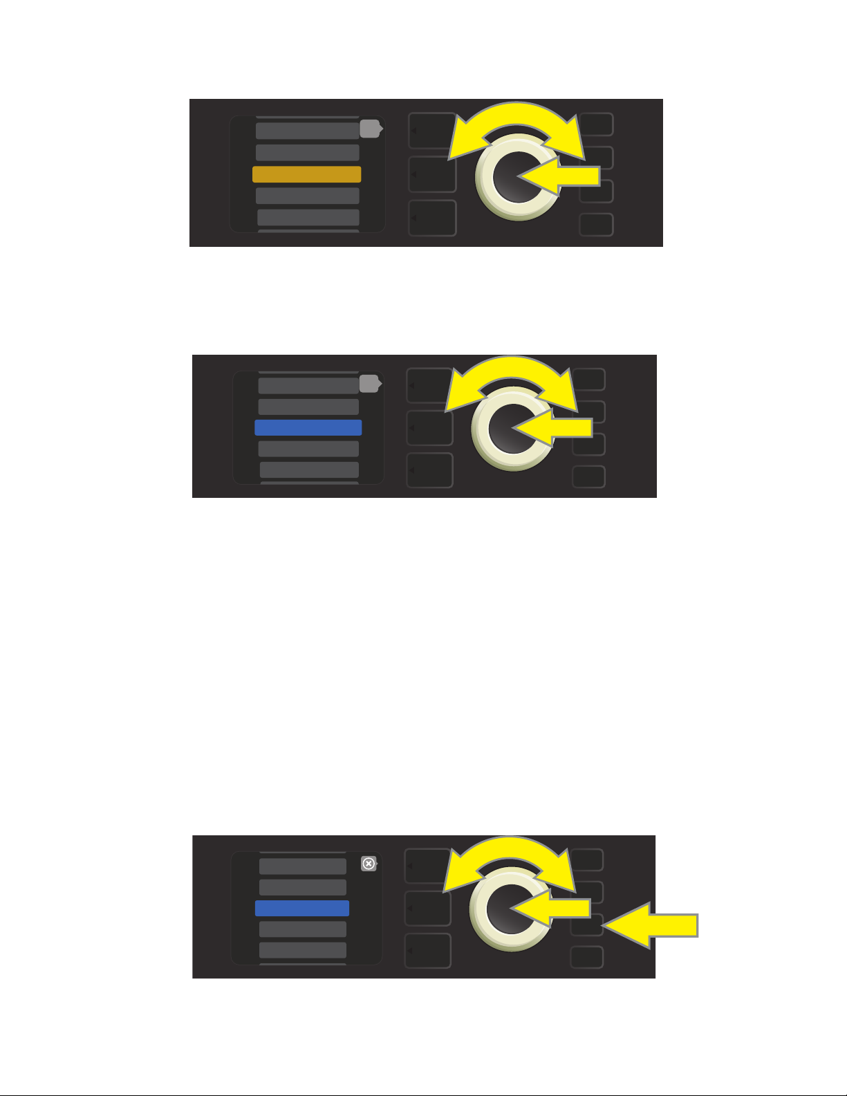
From the list of presets shown. Use the ENCODER to scroll to and select the preset to be moved. When a preset is selected to be moved, the box containing its name changes from blue to amber (see illustration below).
6 - KGB-800
7 - ROCKIN’ PEG
8 - BASSMAN 300>
9 - ’59 BASSMAN>
10 - ’70S BRIT>
back
MENU
Turn the ENCODER to move the amber-highlighted preset to a dierent position in the preset list; then press
the ENCODER to assign the preset to that new position. The amber box containing the preset name will then
change back to blue (see illustration below).
8 - ’59 BASSMAN>
9 - ’70S BRIT>
10 - BASSMAN 300>
11 - BASSMAN TV
12 - BRITISH CO>
back
MENU
Note that when moving a preset to a new position, it assumes the correct sequential numerical value for that
position; accordingly, all other presets are then “shifted” into correct sequential numbering.
CLEARING A PRESET
Rumble Studio 40/Stage 800 presets cannot be deleted. They can, however, be “cleared”—meaning that the
preset remains in place but is “emptied” of its original contents (control settings, amp model, eects). If it is
part of a Setlist, the cleared preset will remain in the Setlist.
Note that when a preset is cleared, its original sequential number will remain in place, and it will by default
contain only the “Studio Preamp” amp model (and its controls).
To clear a preset, rst press the MENU utility button and use the ENCODER to scroll to and select “PRESET
ORGANIZER” (see illustration below).
WIFI
BLUETOOTH
PRESET ORGANIZER
SETLIST
CLOUD PRESETS
MENU
7
Use the ENCODER to scroll to and select the “CLEAR PRESET” option (see illustration below).
CLEAR
“10 - BASSMAN 300”?
WARNING: THIS MAY AFFECT SETLIST(S)
back
MOVE PRESET
CLEAR PRESET
RESTORE PRESETS
MENU
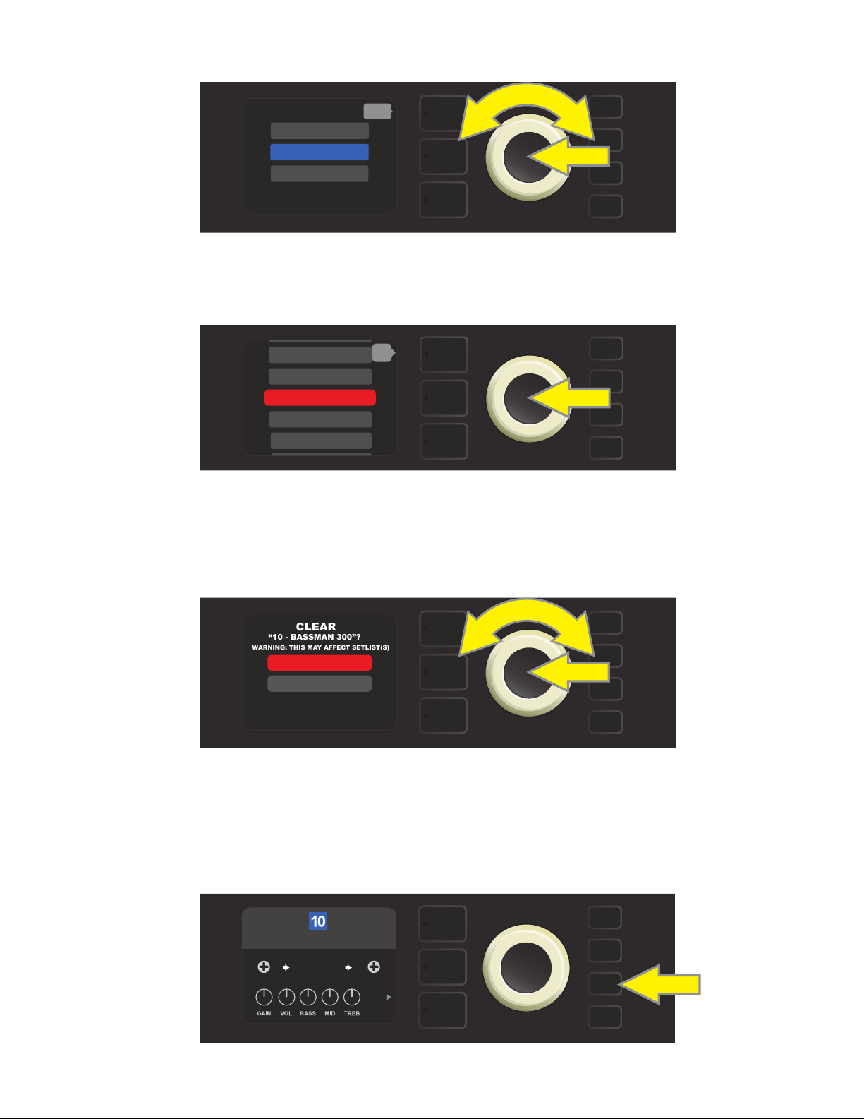
A list of presets will then appear with the preset to be cleared highlighted in red in the middle. Press the
ENCODER on the red-highlighted preset to clear the preset (see illustration below).
8 - ’59 BASSMAN>
9 - ’70S BRIT>
10 - BASSMAN 300>
11 - BASSMAN TV
12 - BRITISH CO>
back
MENU
Rumble Studio 40/Stage 800 will then verify whether the user wants to clear the preset by prompting a
choice of “YES” (clear) or “NO” (do not clear). This prompt will also note that clearing the preset may aect
Setlists (if indeed that preset is included in a Setlist). Use the ENCODER to select “YES” or “NO,” and press the
ENCODER on either option (see illustration below).
YES
NO
MENU
On selecting “YES” (clear preset), the preset will remain in place but will automatically be re-titled “EMPTY.” If
done clearing presets at this point, return to the main menu by pressing the top LAYER BUTTON corresponding to the onscreen prompt “BACK.” To return to the current (and now empty) preset, press the MENU utility
button. As noted above, the now-cleared preset will contain only its original sequential number and the
default “Studio Preamp” amp model (see illustration below).
EMPTY
STUDIO
PREAMP
NONE
MENU
CAB
8

RESTORING PRESETS
RESTORE
FACTORY PRESETS?
WARNING: THIS MAY AFFECT SETLIST(S)
Rumble Studio 40/Stage 800’s PRESET ORGANIZER also includes a “RESTORE PRESETS” option that returns all
presets to the original factory settings. To do this, rst press the MENU utility button and use the ENCODER
to scroll to and select “PRESET ORGANIZER” (see illustration below).
WIFI
BLUETOOTH
PRESET ORGANIZER
SETLIST
CLOUD PRESETS
Use the ENCODER to scroll to and select the “RESTORE PRESETS” option (see illustration below).
back
MOVE PRESET
CLEAR PRESET
RESTORE PRESETS
MENU
MENU
Rumble Studio 40/Stage 800 will then verify whether the user wants to restore all amp presets by prompting
a choice of “YES” (restore) or “NO” (do not restore), made by pressing the LAYER BUTTON corresponding to
either choice (see illustration below).
YES
NO
MENU
9
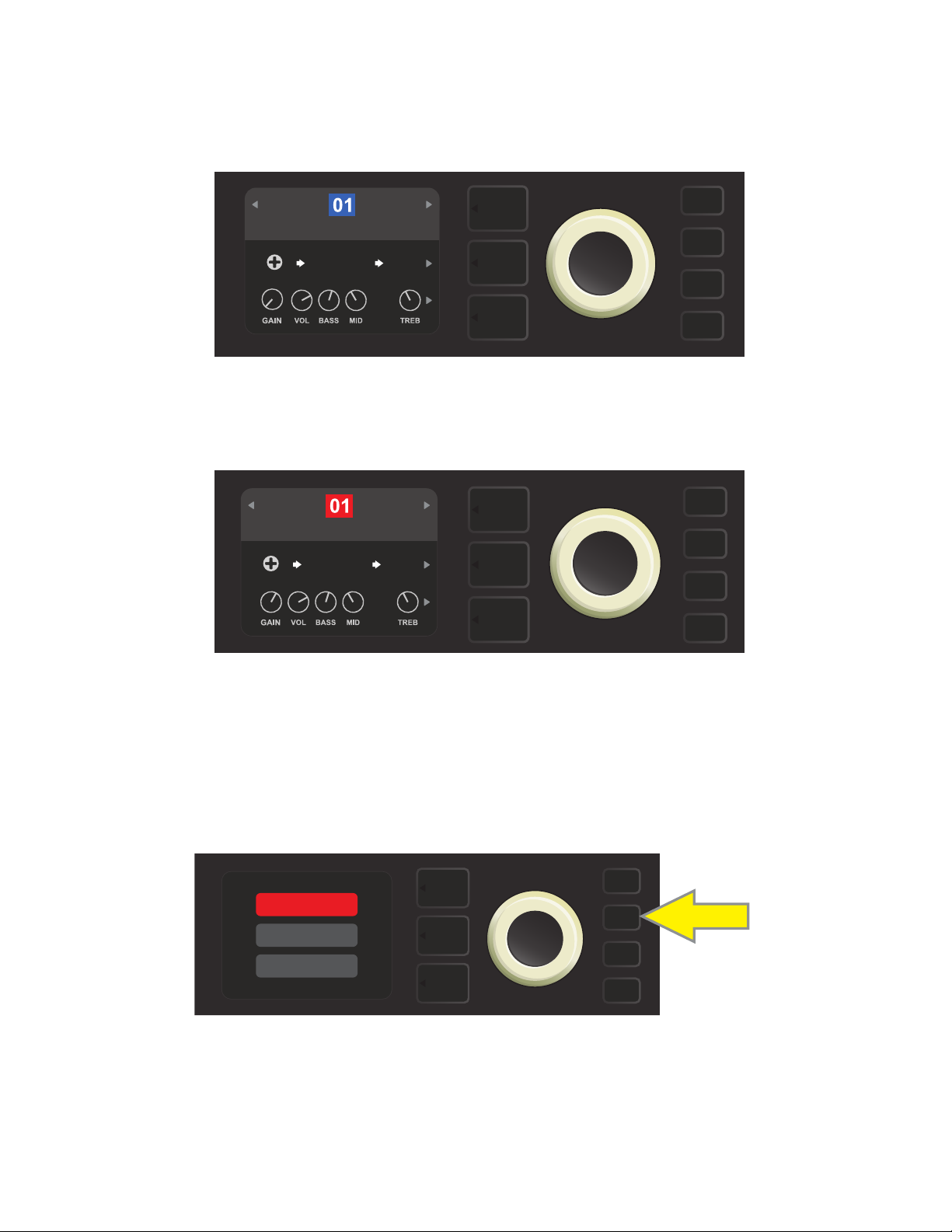
EDITING AND SAVING PRESETS
Within each preset, the amplier control knob settings, amp models, and eects types and parameters can
be tailored to individual preference. When a preset is selected, the box containing its number is blue, indicating that no edits have been made to it (see illustration below).
BASIC BASSMAN CLN
SUPER
BMAN-OD
When edits to a preset have been made, the box containing the preset number changes to red, and the SAVE
utility button illuminates (see illustration below). If an edited setting is not saved, the preset will revert to its previous settings when returning to the preset after leaving it, or when turning the amplier o and back on again.
1000
FREQ
SMALL
ROOM
BASIC BASSMAN CLN
SUPER
BMAN-OD
1000
FREQ
SMALL
ROOM
SAVE
SAVING EDITED PRESETS
Once a preset is edited, there are three options for saving it. These options are accessed by pressing the SAVE
utility button and using the ENCODER to scroll to and select one of the three options, described below.
SAVE: For saving the edited preset using the same name and in its original position (see illustration below).
SAVE
SAVE AS
RENAME
SAVE
SAVE AS: For moving the edited preset to a dierent position and saving it with or without a dierent name.
The preset can be moved to a numbered empty slot, or it can replace (overwrite) an existing preset occupying another numbered slot.
10
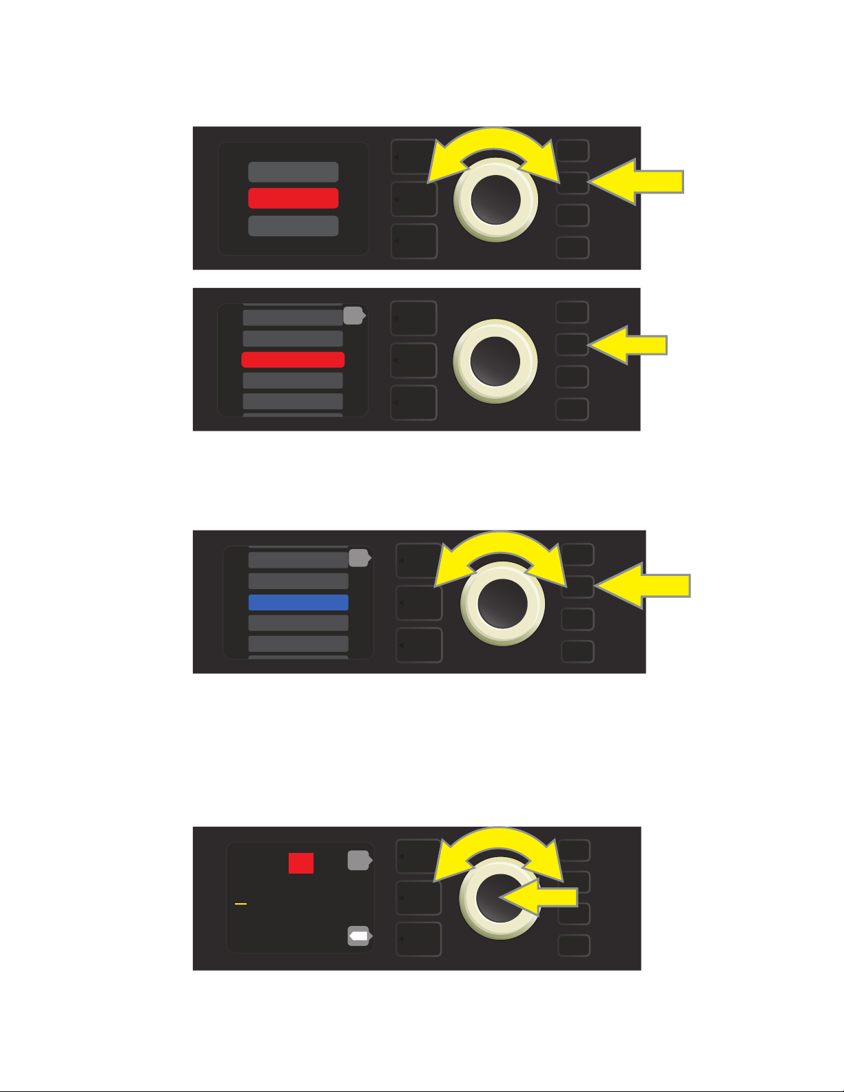
To move the edited preset to an empty slot and save it with the same name, rst press the SAVE utility
button; use the ENCODER to scroll to and select “SAVE AS.” The preset name will be highlighted in red (see
illustrations below).
SAVE
SAVE AS
RENAME
SAVE
199 - EMPTY
200 - EMPTY
1 - RUMBLE V2 C>
2 - RUMBLE V3 C>
3 - RUMBLE V3 D>
back
SAVE
Move the highlighted preset by turning the ENCODER to any empty preset slot (which will then be highlighted in blue); press the SAVE utility button to save the edited preset to the empty slot (see illustration below).
194 - EMPTY
195 - EMPTY
196 - EMPTY
197 - EMPTY
198 - EMPTY
back
SAVE
To move the edited preset to an empty slot and save it with a dierent name, follow the same steps above;
but instead of pressing the SAVE utility button at the end, press the ENCODER to activate a cursor. Enter a new
name by scrolling through and selecting characters by turning and pressing the ENCODER. (see illustration
below). Press the SAVE utility button when renaming is complete, or press the top LAYER button (corresponding with onscreen prompt “back”) to return to the previous screen.
196
R u m b l e V 2 C l e a n
back
SAVE
X
11
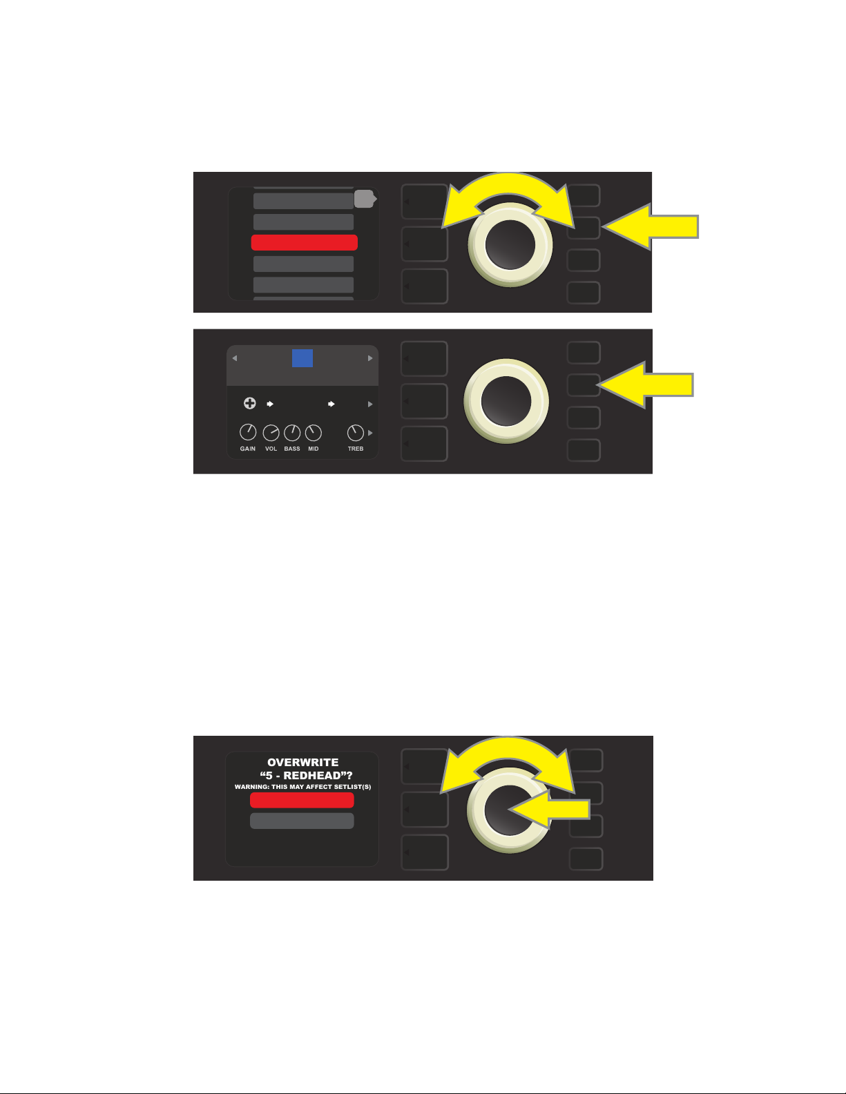
To move the edited preset to a slot already occupied by an existing preset and save it with the same name,
OVERWRITE
“5 - REDHEAD”?
WARNING: THIS MAY AFFECT SETLIST(S)
press the SAVE utility button and use the ENCODER to scroll to and select “SAVE AS” (as described on page 11);
as noted previously, the name of the preset to be moved will be highlighted in red.
Move the highlighted preset by turning the ENCODER to any already-occupied preset slot (red); press the SAVE
utility button to save the edited preset to that slot and overwrite the previous preset (see illustrations below).
13 - BASIC SHOW>
14 - BASIC ’59>
15 - BASSMAN RO>
16 - ’59 BASSMA>
17 - BASIC RUM>
back
SAVE
15
BASIC BASSMAN CLN
SUPER
BMAN-OD
1000
FREQ
SMALL
ROOM
SAVE
Note that when overwriting a preset in this manner, the preset previously assigned to the position selected
is erased from the amplier. The only way to recover it is to use the “RESTORE PRESETS” option in the PRESET
ORGANIZER (see page 9), an option that returns all presets to the original factory settings.
To move the edited preset to a slot already occupied by an existing preset and save it with a dierent name,
press the SAVE utility button and use the ENCODER to scroll to and select “SAVE AS,” after which the name of
the preset to be moved will be highlighted in red (as described above and on page 11). Then move the high-
lighted preset by turning the ENCODER to any already-occupied preset slot (red).
At the new position, press the ENCODER. The user will then be prompted to OVERWRITE the existing preset
in that position. Use the ENCODER to scroll to and select either “YES” or “NO” (see illustration below).
YES
NO
SAVE
Selecting “YES” takes the user to the renaming screen; use the ENCODER to enter a new name using the process
described at the bottom of page 11. Press the SAVE utility button when renaming is complete. Selecting “NO”
returns the user to the previous screen in which the preset name is highlighted in red in its original position.
Note that when overwriting a factory preset in this manner, the preset previously assigned to the position selected is erased from the amplier. The only way to recover a factory preset is to use the “RESTORE PRESETS” op-
tion in the PRESET ORGANIZER (see page 9), an option that returns all presets to the original factory settings.
12
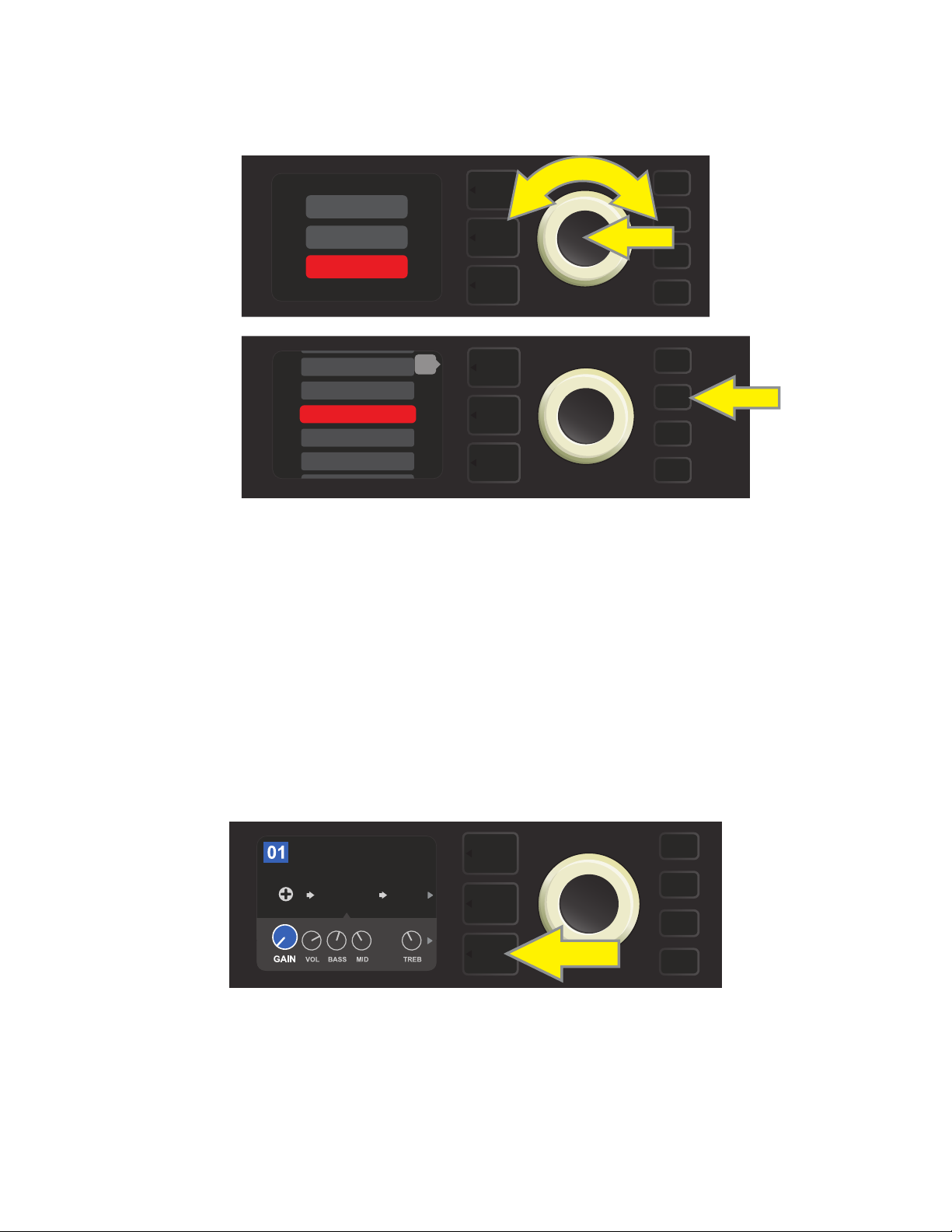
RENAME: For saving the edited preset in its original position and giving it a dierent name. To do this, press
the SAVE utility button and use the ENCODER to scroll to and select “RENAME.” The preset name will be highlighted in red (see illustrations below). Use the ENCODER to enter a new name using the process described on
page 11, then press the SAVE utility button when renaming is complete.
SAVE
SAVE AS
RENAME
199 - EMPTY
200 - EMPTY
1 - RUMBLE V2 C>
2 - RUMBLE V3 C>
3 - RUMBLE V3 D>
back
SAVE
SAVE
EDITING PRESET AMPLIFIER CONTROL KNOB SETTINGS
As noted in the “Control Panel” section above, users can change a preset’s amplier control knob settings by
turning the physical control knobs on the top panel (except for Master Volume). This synchronizes the modied settings of the physical control knobs with their corresponding digital counterparts.
These settings can also be changed by editing the digital control knob positions within the CONTROLS
LAYER, which displays the controls specic to the amp in use. To do this, rst access the CONTROLS LAYER by
pressing its LAYER BUTTON (see illustration below).
BASIC BASSMAN CL
AMPLIFIER
SUPER
BMAN-OD
1000
FREQ
SMALL
ROOM
Press the bottom LAYER BUTTON to access the CONTROLS LAYER for the amp model within the preset.
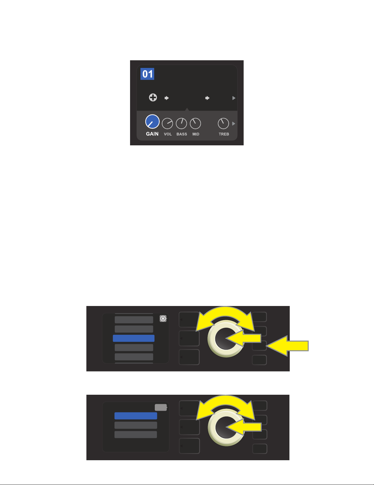
Once in the CONTROLS LAYER, turn and press the ENCODER to scroll through and select a specic digital amp
control knob. Then turn the ENCODER again to change that control’s setting. When a control setting is changed,
the box containing the preset number changes from blue to red (indicating that a preset edit has been made),
and the SAVE utility button illuminates. With the new control setting in place, further edits can then be made or
the SAVE utility button can be pressed to keep completed edits (see illustrations on following page).
13
BASIC BASSMAN CL
SAVE
AMPLIFIER
SUPER
BMAN-OD
1000
FREQ
SMALL
ROOM
Turn the ENCODER to scroll among amp model control knobs.
BASIC BASSMAN CL
AMPLIFIER
SUPER
BMAN-OD
1000
FREQ
SMALL
ROOM
Press the ENCODER to select an amp model control knob for adjustment.
BASIC BASSMAN CL
AMPLIFIER
SUPER
BMAN-OD
SMALL
ROOM
SAVE
1000
FREQ
Turn the ENCODER again to adjust the selected amp model control knob to preference.
Additional amp and control settings can be found by continuing to scroll through the CONTROLS LAYER of
various amp models within the presets. These consist of “deeper” parameters such as (depending on amp)
compression sag, bias and gate controls. Dierent speaker cabinet models are also included. Scroll through,
select, adjust and save these additional parameters in the same manner described directly above (see illus-
trations below).
BASIC ORANGEY DIR
35
AMPLIFIER
BRITISH
COLOUR
4x12
LOW1 LOW
75W
CAB COMP
Close-up detail showing additional amp and control settings found in the CONTROLS LAYER; in this
case for the “British Colour” amp model.
GATE
PRE
POS
LARGE
ROOM
MTCH
SAG
+0.0
%
BIAS
BASIC ORANGEY DIR
35
AMPLIFIER
4x12
LOW1 LOW
75W
CAB COMP
BRITISH
COLOUR
GATE
PRE
POS
LARGE
ROOM
MTCH
SAG
+0.0
%
BIAS
Scroll among, select and adjust additional CONTROLS LAYER amp
and control settings using the ENCODER.
SAVE
14
REPLACING PRESET AMPLIFIER MODELS
BASSMAN 300 PRO
’59 BASSMAN
ROCKIN’ PEG
’70S BRITISH
BRITISH COLOUR
BASSMAN 300 PRO
’59 BASSMAN
ROCKIN’ PEG
’70S BRITISH
BRITISH COLOUR
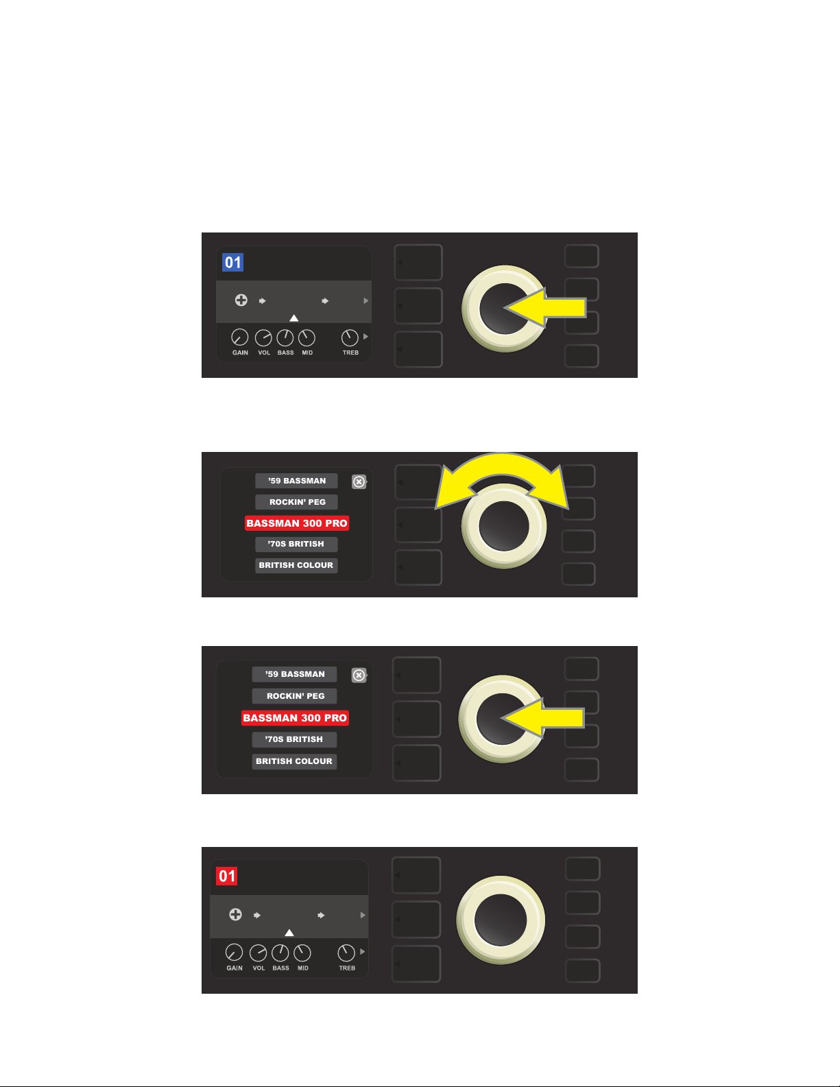
To replace an amplier model within a preset, access the SIGNAL PATH LAYER by pressing its LAYER BUTTON.
The preset amp model will be highlighted. Press the ENCODER to access and scroll through a menu of amp
models; select a new amp model by pressing the ENCODER again. When a new amp model is selected, the
box containing the preset number changes from blue to red (indicating that a preset edit has been made),
and the SAVE utility button illuminates (see illustrations below). With the new amp model in place, further edits
can then be made or the SAVE utility button can be pressed to keep completed edits. Note that pressing the
PRESET LAYER button corresponding to the circled “X” in the DISPLAY WINDOW closes the amp menu.
BASIC BASSMAN CL
AMPLIFIER
SUPER
BMAN-OD
To replace preset amp model highlighted in the SIGNAL PATH LAYER (as indicated here by the white arrow below it and the
label “amplier” above it) with a dierent amp model, rst press ENCODER to access a menu of other amp models.
1000
FREQ
SMALL
ROOM
Turn ENCODER to scroll through menu of amp models.
Press ENCODER again to select a new amp model for the preset.
BASIC BASSMAN CL
AMPLIFIER
BASSMAN
300
1000
FREQ
SMALL
ROOM
SAVE
With the new amp model in place, continue editing other parameters
or press the illuminated SAVE utility button to keep completed edits.
15

AMPLIFIER AND CABINET MODELS
This table lists the preset amplier and speaker cabinet models in Rumble Studio 40/Stage 800, with a brief
description of each. Rumble models will be continually revised and updated; this manual indicates current
amp models in use at time of initial publication.
AMP MODELS
Studio Preamp
Tube Preamp
Rumble® V3
Bassman® TV
Dual Showman®
’59 Bassman®
Rumble V2
Bassman® 300 Pro
Monster
’70s British
Direct-to-mixing-desk studio purity with clean, uncolored tonal response
Similar to the above, but like a tube console for increased harmonic coloration
Based on the clean-to-gritty tone of Fender’s best-selling bass amps
Based on the original-era boom of Fender’s vintage “TV-Front” Bassman
Based on the ’60s/’70s all-tube Fender classic used on big stages everywhere
Based on Fender’s celebrated open-back 4x10 combo of the late 1950s
Based on Fender’s popular Rumble V2 series of 2010-2014
All-tube giant with distinctively versatile tone shaping and blendable overdrive
High-gain all-tube boutique guitar amp model re-imagined for bass
Inspired by a late ’60s/early ’70s Marshall Super Bass, a quintessential early hard-
rock bass amp
British Colour
British Watts
Inspired by the classic cleaner-toned British stack, the original 100-watt Hiwatt
Inspired by the “sludgy” majesty of 1970s-era Orange amps
DR103
Redhead Inspired by the full-range high-end 1990s indispensability of the SWR® Redhead
KGB-800
Rockin’ Peg
Super Bassman
Super Bassman OD
’66 Flip-Top
Rumble, Bassman, Showman and Redhead are trademarks of FMIC. All other non-FMIC product names and trademarks appearing in this manual are
the property of their respective owners and are used solely to identify the products whose tones and sounds were studied during sound model development for this product. The use of these products and trademarks does not imply any aliation, connection, sponsorship, or approval between FMIC and
with or by any third party.
Based on the ’80s/’90s-era power and clarity of the Gallien-Krueger 800RB
Inspired by the seismic all-tube sound of the Ampeg SVT
Based on the “Vintage” channel of Fender’s present-day agship bass amp
Fender’s present-day agship bass amp, with blendable tube overdrive
Based on the beloved mid-’60s Ampeg B-15NF
16

CABINET MODELS
1x8
1x10 Rumble® V2
1x12 Rumble V2
1x15 Rumble V2
1x10 Rumble V3
2x10 Rumble V3
1x15 TV
1x18
2x10 Redhead
2x12 Open
2x12 Sealed
Under-powered vintage small-speaker sound with interesting bass tonality
Variation on single 10” Fender combo amp punch
Variation on single 12” Fender combo amp punch
Variation on single 15” Fender combo amp boom
Based on the tight punch of Fender’s Rumble 40 Combo
Based on Fender’s popular and versatile Rumble 500 Combo
Based on the single 15” boom of Fender’s vintage “TV Front” Bassman®
Based on the single 18” might of SWR’s earth-shaking Big Ben subwoofer
Based on SWR’s acclaimed full-range hi- combo, the Redhead
Based on the sound of the open-back Fender Twin-Reverb®
Based on the sound of the closed-back Fender Bandmaster® cab
2x15 Pro
2x15 D130
4x10 Pro
4x10 Goliath
’59 Bassman
4x12 75 Watt
4x12 GB
4x12 V30
8x10 Vintage
8x10 Neo
8x10 Pro
Based on the deep double wallop of Fender’s 2x15 cab with cast-frame drivers
Based on the Fender Showman® cab with the distinctive attack of JBL® D130F speakers
Based on the powerful punch of Fender’s 4x10 cab with cast-frame drivers
Based on the rst truly full-range, high-end 4x10 cab, the SWR® Goliath
Based on Fender’s celebrated open-back 4x10 combo of the late 1950s
Based on the Marshall 1960B cabinet with four 12” 75-watt Celestion® speakers
Based on a Marshall cabinet with four 12” Celestion® Greenback speakers
Based on a Marshall cabinet with four 12” Celestion® Vintage 30 speakers
Inspired by the old-school seismic might of the Ampeg SVT 8x10 cabinet
Based on Fender’s 8x10 cab with neodymium speaker magnets
Based on Fender’s clear-sounding 8x10 cab with ceramic drivers
1x15 Flip-Top
Rumble, Bassman, Twin Reverb, Bandmaster, Redhead and Goliath are trademarks of FMIC. All other non-FMIC product names and trademarks
appearing in this manual are the property of their respective owners and are used solely to identify the products whose tones and sounds were studied
during sound model development for this product. The use of these products and trademarks does not imply any aliation, connection, sponsorship, or
approval between FMIC and with or by any third party.
Based on a mid-’60s Ampeg B-15NF speaker cabinet
17
EDITING EFFECTS
In addition to amp models, each preset also features various combinations of eects. Eects can be edited in
several ways—they can be bypassed, replaced, moved, added or deleted. Further, the individual settings
of each eect can be modied. Each option is explained below and on the following pages.
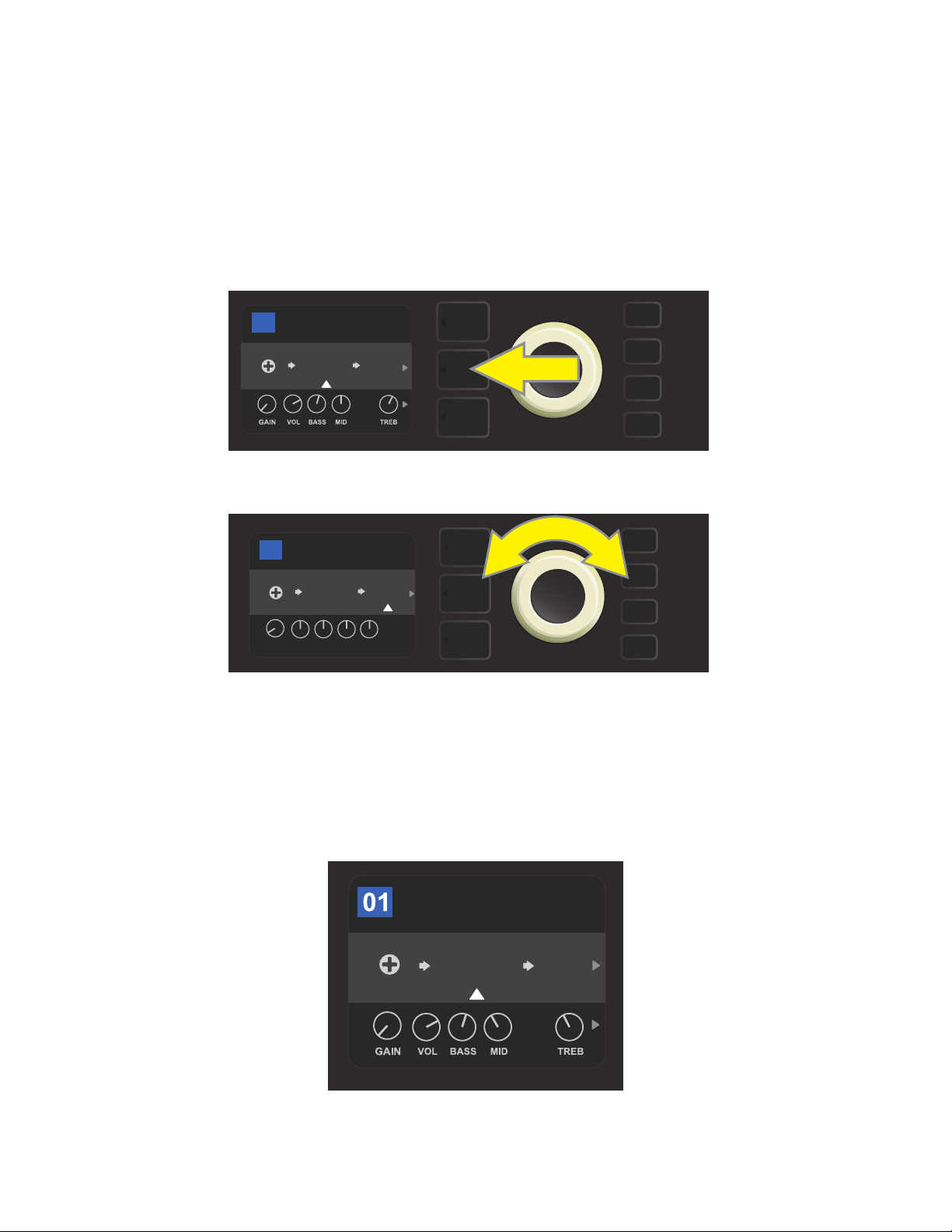
Editing the types of eects in use and their position in the signal path happens in the SIGNAL PATH LAYER. To
do this, rst access the SIGNAL PATH LAYER by pressing its corresponding LAYER BUTTON, which will automatically highlight the amplier model in use rst. To highlight an eect, turn the ENCODER in either direction (see illustrations below). The eect will be highlighted with a white arrow below it and a label above it.
BASIC RUMBLE V2
17
AMPLIFIER
RUMBLE
V2
To access eects, rst press the middle LAYER BUTTON to enter SIGNAL PATH LAYER.
1494
FREQ
SMALL
Hz
ROOM
BASIC RUMBLE V2
17
AMPLIFIER
RUMBLE
LVL DCAY DWLL DIFF TONE
POST FX 1
SMALL
V2
ROOM
POST
TYPE
Turn the ENCODER in either direction to highlight an eect (as indicated
here by the white arrow below it and label above it).
For each preset, note that a placeholder symbol consisting of a plus sign (+) in a circle appears at the right and
left ends of the SIGNAL PATH LAYER (see illustration below). This symbol indicates an open slot into which an effect can be moved or added (see “Adding an Eect,” page 22). In many presets that include one or more eects,
the user must scroll to the far right or far left using the ENCODER in order to see this symbol.
BASIC BASSMAN CL
AMPLIFIER
SUPER
BMAN-OD
SMALL
ROOM
1000
FREQ
Close-up detail of a dierent preset that includes an open slot in which an eect can be placed, marked here by a place-
holder symbol (a plus sign in a circle) at the far left end of the SIGNAL PATH LAYER.
18
BYPASSING AN EFFECT
ADD FX
BYPASS
DELETE
MOVE
REPLACE
There are two ways to bypass eects. The rst is a general on-o feature that simply turns o all eects in all
presets with a single press of a button. The second lets users bypass specic individual eects within a preset.
To turn o (and back on) all Rumble Studio 40/Stage 800 eects in every preset, press the X FX utility button.
There is no option to save; this is merely a quick way to turn all eects o and back on. When pressed, X FX
utility button illuminates and a blue “bypass” label appears above each eect (see illustration below). If specific eects have already been bypassed in a preset, use of the X FX utility button will not turn them back on.
42
FX
BASIC OCTOBOT
OCTO
BOT
RUMBLE
BYPASSBYPASS
SMALL
ROOM
V3
HI-MLO-M
The “X FX” utility button illuminates when pressed, bypassing all eects in all presets (indicated by blue “BYPASS” labels above each eect).
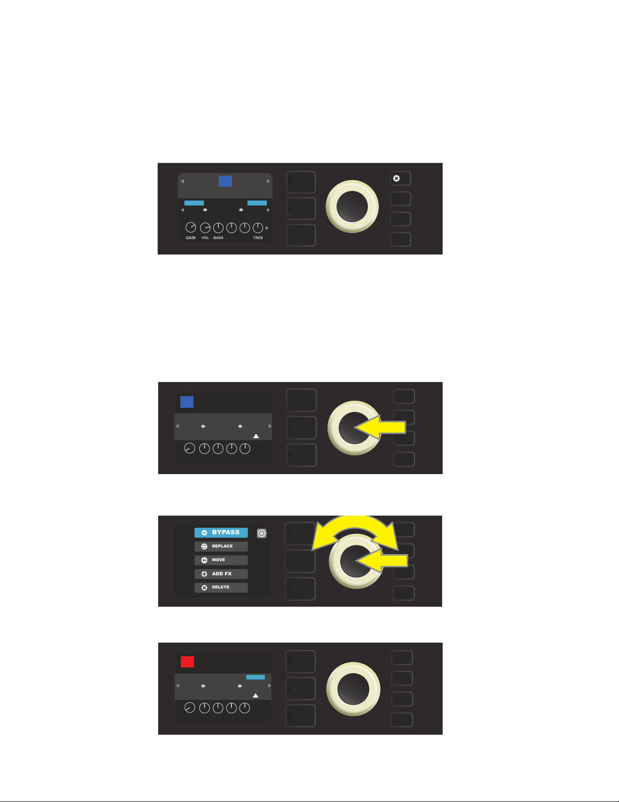
To bypass specic individual eects within a preset, highlight it in the SIGNAL PATH LAYER and press the
ENCODER. Select “BYPASS” from the menu of eects placement options and press the ENCODER again. The
SIGNAL PATH LAYER will then indicate that the eect has been bypassed; the box containing the preset number will change from blue to red (indicating that a preset edit has been made), and the SAVE utility button
will illuminate. With the eect now bypassed, further edits can then be made or the SAVE utility button can
be pressed to keep completed edits (see illustrations below).
BASIC OCTOBOT
42
AMPLIFIER
RUMBLE
OCTO
BOT
LVL DCAY DWLL DIFF TONE
POST FX 1
SMALL
V3
ROOM
POST
TYPE
To bypass a highlighted eect, rst press the ENCODER to access the menu of eects placement options.
Turn ENCODER to highlight “BYPASS” in eects placement options menu, then press the ENCODER to select it.
BASIC OCTOBOT
42
AMPLIFIER
RUMBLE
OCTO
BOT
LVL DCAY DWLL DIFF TONE
BYPASS
SMALL
V3
ROOM
POST
TYPE
SAVE
With the eect bypassed (as indicated here by white arrow below it and blue box containing the label “BYPASS”
above it), continue editing other parameters or press the illuminated SAVE utility button to keep completed edits.
19

REPLACING AN EFFECT
ADD FX
BYPASS
DELETE
MOVE
REPLACE
MODULATION
STOMPBOX
DELAY
REVERB
PARAMETRIC EQ
ENVELOPE FILTER
MODERN BASS OD
GREENBOX
OVERDRIVE
To replace an eect, highlight the eect to be replaced in the SIGNAL PATH LAYER and press the ENCODER.
Select “REPLACE” from the menu of eects placement options and press the ENCODER again. Select one of the
eects categories that will appear—Stompbox, Modulation, Delay or Reverb—and press the ENCODER to access
the eects in that category. Scroll through the eects and press the ENCODER to select one as a replacement.
The SIGNAL PATH LAYER will then display the new eect and indicate that the original eect has been replaced;
the box containing the preset number will change from blue to red (indicating that a preset edit has been
made), and the SAVE utility button will illuminate. With the eect now replaced, further edits can then be made
or the SAVE utility button can be pressed to keep completed edits (see illustrations below and on next page).
Note that pressing the PRESET LAYER button corresponding to the circled “X” in the DISPLAY WINDOW closes
the eects placement option and eects category menus; pressing it when it corresponds to the label “back”
(as on the eects menu) returns the user to the previous screen.
BASIC OCTOBOT
42
AMPLIFIER
OCTO
RUMBLE
BOT
LVL DCAY DWLL DIFF TONE
POST FX 1
SMALL
V3
ROOM
POST
TYPE
To replace a highlighted eect, rst press the ENCODER to access the menu of eects placement options.
Turn the ENCODER to highlight “REPLACE” in eects placement options menu, then press the ENCODER to select it.
Turn the ENCODER to highlight an eects category, then press ENCODER to select it.
back
Turn the ENCODER to highlight a replacement eect, then press ENCODER to select it.
20

BASIC OCTOBOT
ADD FX
BYPASS
DELETE
MOVE
REPLACE
42
OCTO
BOT
AMPLIFIER
RUMBLE
POST FX 1
BASS
V3
OD
PRESBLENDDRIVELEVEL
SAVE
With the eect replaced (as indicated here by white arrow below it and label above it), continue editing other
parameters or press the illuminated SAVE utility button to keep completed edits.
MOVING AN EFFECT
To move an eect to a dierent position in the signal path, highlight the eect to be moved in the SIGNAL
PATH LAYER and press the ENCODER. Select “MOVE” from the menu of eects placement options and press
the ENCODER again. An amber box will appear around the selected eect name, along with a blinking white
arrow indicating that the eect is ready to be moved. Turn the ENCODER to reposition the selected eect;
press the ENCODER to place the eect in a new position.
The SIGNAL PATH LAYER will then display the eect in its new position; the box containing the preset number
will change from blue to red (indicating that a preset edit has been made), and the SAVE utility button will illuminate. With the eect now moved, further edits can then be made or the SAVE utility button can be pressed
to keep completed edits (see illustrations below and on next page).
BASIC OCTOBOT
42
AMPLIFIER
RUMBLE
OCTO
BOT
LVL DCAY DWLL DIFF TONE
POST FX 1
SMALL
V3
ROOM
POST
TYPE
To move a highlighted eect, rst press the ENCODER to access the menu of eects placement options.
Turn the ENCODER to highlight “MOVE” in eects placement options menu, then press the ENCODER to select it.
BASIC OCTOBOT
42
OCTO
BOT
AMPLIFIER
RUMBLE
POST FX 1
SMALL
V3
ROOM
POST
LVL DCAY DWLL DIFF TONE
TYPE
The selected eect, highlighted with a white arrow below it and label above it, appears in an amber box indi-
cating that it is ready to be moved to a dierent position in the signal path by turning the ENCODER.
21

BASIC OCTOBOT
42
PRE FX 2
SMALL
OCTO
BOT
ROOM
LVL DCAY DWLL DIFF TONE
AMPLIFIER
RUMBLE
V3
POST
TYPE
After moving the selected eect by turning the ENCODER, press the
ENCODER to select its new position in the signal path.
BASIC OCTOBOT
42
PRE FX 2
SMALL
OCTO
BOT
ROOM
LVL DCAY DWLL DIFF TONE
AMPLIFIER
RUMBLE
V3
POST
TYPE
SAVE
With the eect moved to a new position (as indicated here by white arrow below it and label above it), contin-
ue editing other parameters or press the illuminated SAVE utility button to keep completed edits.
ADDING AN EFFECT
There are two ways to add an eect.
In the rst method, highlight one of the two placeholder plus-sign symbols in the SIGNAL PATH LAYER by
turning the ENCODER. The circle containing the plus-sign symbol will turn green. Press the ENCODER to see
a menu of eects categories—Stompbox, Modulation, Delay and Reverb. Highlight a category by turning
the ENCODER, then press the ENCODER to access the eects in that category. Scroll through the eects and
press the ENCODER to select an eect.
The SIGNAL PATH LAYER will then display the newly added eect in a green box with a blinking white arrow
below it and a label above it, indicating that the eect can be moved to a dierent position (if preferred) by
turning and then pressing the ENCODER.
When an eect is added, the box containing the preset number will change from blue to red (indicating that
a preset edit has been made), and the SAVE utility button will illuminate. With the eect now added, further
edits can then be made or the SAVE utility button can be pressed to keep completed edits (see illustrations
below and on next page). Note that pressing the PRESET LAYER button corresponding to the circled “X” in the
DISPLAY WINDOW closes the eects category and eect menus; pressing it when it corresponds to the label
“back” returns the user to the previous screen.
RUMBLE V3 OD
05
AMPLIFIER
RUMBLE
V3
To add an eect, highlight the placeholder plus-sign symbol by turning the ENCODER to it. The circle contain-
ing the plus-sign symbol will turn green. Press the ENCODER to access a menu of eects categories.
22

Select an eects category by scrolling to it and pressing the ENCODER.
MODULATION
STOMPBOX
DELAY
REVERB
GREENBOX
MODERN BASS OD
PARAMETRIC EQ
ENVELOPE FILTER
BLACKBOX
back
Select an eect by scrolling to it and pressing the ENCODER.
RUMBLE V3 OD
05
AMPLIFIER
RUMBLE
POST FX 1
V3
BASS
OD
PRESBLENDDRIVELEVEL
The newly added eect, highlighted with a white arrow below it and label above it, appears in a green box indi-
cating that it can be left in place or moved to a dierent position in the signal path by turning the ENCODER.
RUMBLE V3 OD
05
PRE FX 1
BASS
OD
AMPLIFIER
RUMBLE
V3
PRESBLENDDRIVELEVEL
After moving the newly added eect by turning the ENCODER,
press the ENCODER to select its new position in the signal path.
RUMBLE V3 OD
05
PRE FX 1
BASS
OD
AMPLIFIER
RUMBLE
V3
PRESBLENDDRIVELEVEL
SAVE
With the added eect in position (as indicated here by white arrow below it and label above it), continue edit-
ing other parameters or press the illuminated SAVE utility button to keep completed edits.
23

In the second method of adding an eect, highlight an existing eect in the SIGNAL PATH LAYER and press
ADD FX
BYPASS
DELETE
REPLACE
MODULATION
STOMPBOX
DELAY
REVERB
GREENBOX
MODERN BASS OD
PARAMETRIC EQ
ENVELOPE FILTER
BLACKBOX
the ENCODER. Select “ADD FX” from the menu of eects placement options and press the ENCODER again.
Select one the four eects categories that will appear and press the ENCODER to access the eects in that
category. Scroll through the eects and press the ENCODER to select an eect.
The SIGNAL PATH LAYER will then display the newly added eect in a green box with a blinking white arrow
below it and a label above it, indicating that the eect can be moved to a dierent position (if preferred) by
turning and then pressing the ENCODER.
When an eect is added, the box containing the preset number will change from blue to red (indicating that a
preset edit has been made), and the SAVE utility button will illuminate. With the eect now added, further edits can then be made or the SAVE utility button can be pressed to keep completed edits (see illustrations below
and on next page).
BASIC OCTOBOT
42
AMPLIFIER
OCTO
RUMBLE
BOT
LVL DCAY DWLL DIFF TONE
In another way to add an eect, highlight an existing eect within a preset by turning the
ENCODER to it and pressing the ENCODER to see a menu of four eects categories.
POST FX 1
SMALL
V3
ROOM
POST
TYPE
MOVE
Select “ADD FX” in the eects placement options menu by scrolling to it and pressing the ENCODER.
Select an eects category by scrolling to it and pressing the ENCODER.
back
Select an eect by scrolling to it and pressing the ENCODER.
24

BASIC OCTOBOT
42
AMPLIFIER
RUMBLE
V3
SMALL
ROOM
POST FX 2
BASS
OD
PRESBLENDDRIVELEVEL
The newly added eect, highlighted with a white arrow below it and label above it, appears in an green box
indicating that it can be left in place or moved to a dierent position in the signal path by turning the ENCODER.
BASIC OCTOBOT
42
AMPLIFIER
RUMBLE
POST FX 1
BASS
V3
OD
SMALL
ROOM
PRESBLENDDRIVELEVEL
After moving the newly added eect by turning the ENCODER, press the ENCODER to select its new position in the signal path.
BASIC OCTOBOT
42
AMPLIFIER
RUMBLE
POST FX 1
BASS
V3
OD
SMALL
ROOM
SAVE
PRESBLENDDRIVELEVEL
With the added eect in position (as indicated here by white arrow below it and label above it), continue edit-
ing other parameters or press the illuminated SAVE utility button to keep completed edits.
DELETING AN EFFECT
To delete an eect from the signal path, highlight the eect in the SIGNAL PATH LAYER and press the ENCODER. Select “DELETE” from the menu of eects placement options and press the ENCODER again; the
eect will be removed from the signal path and another eect in use (if any) will shift into its place. If the
deleted eect was the only eect in the signal path (pre or post), a placeholder symbol consisting of a plus
sign (+) in a circle will appear in its spot.
When an eect is deleted, the box containing the preset number will change from blue to red (indicating
that a preset edit has been made), and the SAVE utility button will illuminate. With the eect now deleted,
further edits can then be made or the SAVE utility button can be pressed to keep completed edits (see illus-
trations below and on next page).
BASIC OCTOBOT
42
OCTO
BOT
AMPLIFIER
RUMBLE
POST FX 1
SMALL
V3
ROOM
POST
LVL DCAY DWLL DIFF TONE
TYPE
To delete a highlighted eect, rst press the ENCODER to access the menu of eects placement options.
25

Select “DELETE” in the eects placement options menu by scrolling to it and pressing the ENCODER.
ADD FX
BYPASS
DELETE
MOVE
REPLACE
BASIC OCTOBOT
42
OCTO
BOT
AMPLIFIER
RUMBLE
V3
SAVE
The SIGNAL PATH LAYER will then show the eect has been deleted (as indicated by white arrow), either by replacing
it with a plus-sign placeholder symbol (as seen here) or by shifting another eect (if present) into its position.
EDITING EFFECTS SETTINGS
To edit the control settings of a particular eect, turn the ENCODER to highlight the eect in the SIGNAL
PATH LAYER, then press the CONTROLS LAYER button, which presents the individual controls for each eect.
Turn the ENCODER to scroll through available eect controls, which will each turn blue as they’re highlighted, and press the ENCODER to select a specic eect control, which will then turn red.
After selecting a specic eect control, turn the ENCODER to edit that specic eect control to preference,
and press the ENCODER again to keep the edited eect control setting. The edited eect control will then
turn from red back to blue. When an eect control is edited, the box containing the preset number will
change from blue to red (indicating that a preset edit has been made), and the SAVE utility button will illuminate. With the eect now edited, further eects control edits can then be made or the SAVE utility button can
be pressed to keep completed preset edits (see illustrations below and on next page).
FUNKY MONKEY
76
AMPLIFIER
RUMBLE
ENV
FILTER
635
ms
TIME FDBK
To edit the settings of a particular eect, highlight the eect in the SIGNAL PATH layer
by scrolling to it with the ENCODER; then press the CONTROLS LAYER button.
POST FX 1
STEREO
V2
ECHO
FREQ
RESONLEVEL
26

FUNKY MONKEY
76
ENV
FILTER
LEVEL
AMPLIFIER
RUMBLE
635
ms
TIME FDBK
POST FX 1
STEREO
V2
ECHO
FREQ
RESON
In the CONTROLS LAYER, highlight an eect control by scrolling to it
using the ENCODER; each eect control turns blue as it’s highlighted.
FUNKY MONKEY
76
ENV
FILTER
LEVEL
AMPLIFIER
RUMBLE
635
ms
TIME FDBK
V2
FREQ
POST FX 1
STEREO
ECHO
RESON
Press the ENCODER to select a specic eect control for adjustment, which will then turn red.
FUNKY MONKEY
76
ENV
FILTER
AMPLIFIER
RUMBLE
POST FX 1
STEREO
V2
ECHO
635
ms
FREQ
LEVEL
TIME FDBK
RESON
Turn the ENCODER to edit the selected eect control to preference.
FUNKY MONKEY
76
ENV
FILTER
LEVEL
AMPLIFIER
RUMBLE
635
ms
TIME FDBK
POST FX 1
STEREO
V2
ECHO
FREQ
RESON
SAVE
Press the ENCODER to keep the edited eect control setting; the eect control will return to blue.
FUNKY MONKEY
76
ENV
FILTER
LEVEL
AMPLIFIER
RUMBLE
635
ms
TIME FDBK
POST FX 1
STEREO
V2
ECHO
FREQ
RESON
SAVE
With the specic eect control edited to preference, continue editing other parameters
or press the illuminated SAVE utility button to keep completed edits.
27

USING THE TAP TEMPO BUTTON
In presets that include Modulation eects, Delay eects or both*, the TAP utility button ashes in time with
the default rate of the rst delay eect in the signal path (or rst modulation eect if no delay eect is present).
This rate can be left as is, or it can be modied using the TAP utility button. To set a new TAP tempo, tap the
ashing TAP utility button at the desired tempo at least two times (see illustration below). The TAP utility button
will function regardless of which layer is highlighted (PRESET LAYER, SIGNAL PATH LAYER or CONTROLS LAYER).
76
FUNKY MONKEY
RUMBLE
ENV
FILTER
To change the tempo of the rst delay eect (or modulation eect if no delay eect is present), tap
Various time parameters for all delay and modulation eects in the signal path can be adjusted in the CONTROLS LAYER without use of the TAP utility button. In the SIGNAL PATH LAYER, use the ENCODER to highlight the delay or modulation eect to be modied; its controls will then appear in the CONTROLS LAYER.
Enter the CONTROLS LAYER by pressing its corresponding layer button, and scroll to the time parameter to
be changed using the ENCODER. Press and turn the ENCODER to select and adjust the desired time value,
during which the window containing the time value will turn red; press the ENCODER again to keep the new
time value (see illustration below).
STEREO
1494
FREQ
ECHO
Hz
V2
the TAP utility button at the desired tempo.
TAP
FUNKY MONKEY
76
ENV
FILTER
643ms
TIME
AMPLIFIER
RUMBLE
FDBK
POST FX 1
STEREO
V2
ECHO
FREQ
RESONLEVEL
TAP
Delay and modulation eects tempos can also be changed by highlighting the time parameter’s numerical value in the
CONTROLS LAYER, then pressing and turning the ENCODER to set the desired tempo.
* Rumble Studio 40/Stage 800 modulation and delay eects are listed on pages 30 and 31.
28

EFFECTS TYPES
Rumble Studio 40/Stage 800 onboard eects are organized into four category menus: Stompbox eects
(18), Modulation eects (13), Delay eects (9) and Reverb eects (12). Names and descriptions of each
appear below, by category. Rumble Studio 40/Stage 800 eects will be continually revised and updated; this
manual indicates current eect types in use at time of initial publication.
STOMPBOX EFFECTS
Modern Bass OD DI with overdrive inspired by the Tech 21 SansAmp Bass Driver
Greenbox
Overdrive eect inspired by the original late-’70s Ibanez TS808 Tube
Screamer
Overdrive Versatile Fender overdrive specially designed for exibilty
Blackbox Distortion eect inspired by the Pro Co RAT
Yellowbox Distortion eect inspired by the ’70s-era MXR Distortion Plus
Orangebox Distortion eect inspired by the original late-’70s Boss DS-1
Big Fuzz Distortion eect inspired by the Electro-Harmonix Big Mu
Varifuzz Versatile Fender fuzz with bass tightness control
Octobot Synth-like combination of octave-down eect plus octave-up fuzz
Ranger Boost
Distortion eect inspired by the ’60s-era Dallas Rangemaster Treble
Booster
Simple Comp Compressor eect inspired by the classic MXR Dyna Comp
Compressor Compressor with added gain, threshold, attack and release controls
Pedal Wah
Touch Wah
All non-FMIC product names and trademarks appearing in this manual are the property of their respective owners and are used solely to identify the products whose tones
and sounds were studied during sound model development for this product. The use of these products and trademarks does not imply any aliation, connection, sponsorship, or approval between FMIC and with or by any third party.
Dual-mode wah inspired by the Dunlop Cry Baby and ’60s-era Vox Clyde
McCoy wah pedal
Similar to Pedal Wah above, but controlled by picking
dynamics rather than an expression pedal
29

STOMPBOX EFFECTS (CONTINUED)
Envelope Filter Inspired by the funktastic 1970s Mu-Tron III.
EQ Parametric Parametric midrange equalizer plus bass and treble controls
EQ7 Graphic (Bass) Seven-band graphic equalizer based on the Boss GE-7B
EQ7 Graphic (Wide) Seven-band graphic equalizer based on the Boss GEB-7
MODULATION EFFECTS
Note that the TAP utility button works with Rumble Studio 40/Stage 800 modulation eects, and ashes
when a preset using one or more modulation eects is in use.
Sine Chorus
Triangle Chorus
Sine Flanger
Triangle Flanger
Vibratone
Vintage Tremolo
Sine Tremolo
Ring Modulator
Smoothly rounded chorus eect that uses a sine
wave for modulation
Distinctive chorus eect that uses a triangle
wave for modulation
Smoothly rounded anging eect that uses a sine
wave for modulation
Distinctive anging eect that uses a triangle
wave for modulation
Classic late-’60s/early-’70s Fender eect with a
rotating speaker bae
Classic Fender “stuttering” photoresistor tremolo, as heard in
Fender amps such as the Twin Reverb
Smoothly pulsating tube bias tremolo, as heard in amps such
as the Fender Princeton Reverb
Creatively non-harmonic dissonance from the early era
of electronic music
Step Filter
Phaser
All non-FMIC product names and trademarks appearing in this manual are the property of their respective owners and are used solely to identify the products whose tones
and sounds were studied during sound model development for this product. The use of these products and trademarks does not imply any aliation, connection, sponsorship, or approval between FMIC and with or by any third party.
Rhythmically choppy modulation eect that dices notes into
distinctly alternating “steps”
Long-indispensable jetliner “whoosh” heard on
countless recordings
30

MODULATION EFFECTS (CONTINUED)
Phaser 90 Phase shifter eect inspired by the classic ’70s MXR Phase 90
Pitch Shifter
Diatonic Pitch
Simple pitch shifter that adds another note above or below
the dry signal pitch
Pitch shifter that produces a chosen musical interval
to create harmonized notes in key
DELAY EFFECTS
Note that the TAP utility button works with Rumble Studio 40/Stage 800 delay eects, and ashes when a
preset using one or more delay eects is in use.
Mono Delay Clean, simple and pristine signal repetition
Tape Delay
Based on the analog classic Maestro Echoplex, which had
tape imperfections that created distinctive “wow” and “utter”
Stereo Tape Similar to Tape Delay above, but with stereo expansion
Multi Tap
Mono Echo Filter
Stereo Echo Filter
Reverse Delay
Ping Pong Delay
Ducking
All non-FMIC product names and trademarks appearing in this manual are the property of their respective owners and are used solely to identify the products whose tones
and sounds were studied during sound model development for this product. The use of these products and trademarks does not imply any aliation, connection, sponsorship, or approval between FMIC and with or by any third party.
Rhythmic delay that can be subdivided into multiple “taps”
with diering time intervals
Mono echo with an evenly spaced wah-like eect
on the signal repetitions
Stereo echo with an evenly spaced wah-like eect
on the signal repetitions
Reverses the shape of notes for the classic
“backwards guitar” eect
Repetitions in the stereo eld alternate between right and
left, imparting a “ping pong” eect
Delayed notes “duck” out of the way while playing, and
ll in gaps when not playing
31

REVERB EFFECTS
Small Hall
Large Hall
Small Room
Large Room
Simulates the kind of bright reverb often heard in,
for example, a hall the size of a movie theater
Strong, bright reverb simulating the size of, for example, a
major performance hall and other large, cavernous spaces
Warmer, less echo-y reverb typical of smaller spaces
and classic echo chambers
Warm-sounding kind of reverb heard in larger rooms, such as
many nightclubs
’63 Spring Classic early-’60s standalone Fender reverb eect
’65 Spring Fender reverb eect built into classic mid-’60s Fender amps
Large Plate
Arena
The reverb type heard on countless recordings, based on
the classic (and pool table-sized) EMT 140
Simulates the long-trailing reverberation typical of
large stadiums and arenas
Ambient
Small Plate
Shimmer
GA-15 Reverb
All non-FMIC product names and trademarks appearing in this manual are the property of their respective owners and are used solely to identify the products whose tones
and sounds were studied during sound model development for this product. The use of these products and trademarks does not imply any aliation, connection, sponsorship, or approval between FMIC and with or by any third party.
Subtle reverb eect typical of notably smaller spaces (even
smaller than Small Room reverb above)
Resonantly metallic reverb with more density and atness
than room and hall reverbs
Sonically radiant combination of reverb and
two-octave pitch shift
Based on the ’60s-era Gibson GA-15 guitar amp reverb,
unique in its ability to go “full wet” (no dry signal)
32

MENU FUNCTIONS
Just to the right of the ENCODER is a vertical column of four utility buttons. The third one down is the MENU
utility button, which enables access to a variety of Rumble Studio 40/Stage 800 special functions (see illustra-
tion below). These functions are referenced elsewhere in this manual; all are listed and briey described here.
WIFI
BLUETOOTH
PRESET ORGANIZER
SETLIST
CLOUD PRESETS
After pressing the MENU utility button, use the ENCODER to scroll through and select one of Rumble Studio
40/Stage 800’s 10 dierent MENU functions. These functions are:
SETLIST: For creation and use of Setlists containing user-selected groups of presets (see pages 34-37).
CLOUD PRESETS: Enables cloud preset storage and use (see pages 59-60).
TUNER: Enables use of Rumble Studio 40/Stage 800’s built-in chromatic tuner (see page 43).
MENU
GLOBAL EQ: Enables access to dierent equalization curves for easier adjustment of overall amp response
to dierent acoustic environments (see page 58).
FOOTSWITCH: For selection of MGT-4 footswitch and EXP-1 Expression Pedal (see pages 45-56).
AMP SETTINGS: Enables restoration of factory presets and amplier settings (see page 57).
ABOUT THIS AMP: Displays the amp’s current rmware version (see page 60).
WIFI: For turning WiFi on/o, selecting and connecting to a network, and adding a password (see pages 38-40).
BLUETOOTH: For accessing and using Rumble Studio 40/Stage 800’s Bluetooth functionality (see pages 41-42).
PRESET ORGANIZER: For moving, renaming and clearing presets; and for restoring all presets to original
factory settings (see pages 6-9).
33

SETLISTS
For individual convenience, presets can be grouped together in “Setlists.” These are user-created groups containing any arrangement of presets ideal for a particular situation—a gig or rehearsal, a favorites list, genre,
artist list, etc. Simple to create, edit, name and even delete, Setlists personalize and streamline the Rumble
Studio 40/Stage 800 experience so that users can access multiple presets quickly and easily. Presets within a
given Setlist can also be selected using the MGT-4 Footswitch (see page 49).
To create a Setlist, rst press the MENU utility button and use the ENCODER to scroll to and select SETLISTS:
BLUETOOTH
PRESET ORGANIZER
SETLIST
CLOUD PRESETS
TUNER
A green plus-sign box will appear; press the ENCODER on it to create a new Setlist:
MENU
MENU
A blue box labeled “SETLIST 1” will appear; press the ENCODER on SETLIST 1 to begin adding presets to it:
SETLIST 1
MENU
The green plus-sign box will then reappear; press the ENCODER on it to see a list of presets to select from:
back
MENU
Use the ENCODER to scroll among presets to add to SETLIST 1, then press the ENCODER to select a desired preset:
9 - ’59 BASSMAN 4X>
10 - ’70S BRITISH
11 - BASSMAN TV
12 - BRITISH COLO>
13 - BRITISH WATT>
back
MENU
34

The selected preset is now added to SETLIST 1; repeat the previous two steps to add additional presets to
SETLIST 1. Once multiple presets have been added to SETLIST 1, use the ENCODER to scroll through and activate dierent presets within the selected Setlist:
1 11 - BASSMAN TV
2 5 - REDHEAD
3 6 - KGB-800
4 9 - ’59 BASSMAN 4X>
5 15 - STUDIO PREAM>
back
MENU
When nished creating and using a Setlist, return to main preset mode by pressing the top LAYER BUTTON.
Note that when doing this, the PRESET LAYER will display whichever preset was last highlighted in the Setlist:
1 11 - BASSMAN TV
2 5 - REDHEAD
3 6 - KGB-800
4 9 - ’59 BASSMAN 4X>
5 15 - STUDIO PREAM>
back
MENU
To create subsequent additional Setlists, repeat the steps on page 34 and above. These will automatically be
labeled “SETLIST 2,” “SETLIST 3” and so on in numerical order.
DELETING AN INDIVIDUAL PRESET FROM A SETLIST
Once a Setlist is created, individual presets within them can easily be deleted if necessary (to delete an entire
Setlist, see page 37). To delete a single preset within a Setlist, highlight the preset to be deleted by scrolling to
it using the ENCODER; press the CONTROLS LAYER button corresponding to the “gear” icon in the DISPLAY
WINDOW:
1 11 - BASSMAN TV
2 5 - REDHEAD
3 6 - KGB-800
4 9 - ’59 BASSMAN 4X>
5 15 - STUDIO PREAM>
back
MENU
“DELETE” will then appear in a blue box; press the ENCODER on it to delete that preset. Alternately, press the PRESET LAYER button corresponding to “back” in the DISPLAY WINDOW to not delete the preset from the Setlist:
back
DELETE
MENU
35

NAMING SETLISTS
For personalized organization, a Setlist can be given a name other than its numerical designation (i.e., “SETLIST 1,” SETLIST 2,” etc.). This can be any name the user wants. To name a Setlist, rst press the MENU utility
button and use the ENCODER to scroll to and select SETLISTS, then use the ENCODER to scroll to the Setlist
to be renamed (see illustrations below).
BLUETOOTH
PRESET ORGANIZER
SETLIST
CLOUD PRESETS
TUNER
SETLIST 1
SETLIST 2
Press the LAYER BUTTON corresponding with the “gear” icon, then use the ENCODER to scroll to and selectthe “RENAME SETLIST” option (see illustration below).
MENU
MENU
back
DELETE SETLIST
RENAME SETLIST
MENU
Use the ENCODER to enter a new name using the process described on page 11 (see illustration below).
ENTER NAME:
S e t l i s t 2
back
X
When entering a new Setlist name is completed, press the LAYER BUTTON corresponding to the onscreen
prompt “done.” The Setlist menu will then appear with the newly named Setlist in place (see illustrations be-
low and on next page).
ENTER NAME:
C o u n t B a s s y
back
X
36

SETLIST 1
COUNT BASSY
MENU
DELETING SETLISTS
An entire Setlist can also be deleted. To do this, enter the Setlist menu by pressing the MENU utility button
and using the ENCODER to scroll to and select SETLISTS (see illustration below).
BLUETOOTH
PRESET ORGANIZER
SETLIST
CLOUD PRESETS
TUNER
Use the ENCODER to scroll to the Setlist to be deleted; then press the bottom LAYER BUTTON corresponding
with the “gear” icon in the DISPLAY WINDOW (see illustration below).
MENU
SETLIST 1
SETLIST 2
MENU
From the menu shown, use the ENCODER to scroll to “DELETE SETLIST”; press the ENCODER on it to delete
the selected Setlist (see illustrations below). Alternately, press the top LAYER BUTTON corresponding to “back”
(x) in the DISPLAY WINDOW to not delete the Setlist. After a Setlist is deleted, the user is returned to the Setlist menu.
back
DELETE SETLIST
RENAME SETLIST
SETLIST 1
MENU
37
MENU

WIFI USE
Rumble Studio 40/Stage 800’s WiFi connectivity delivers easy wireless network access, enabling users to get
the latest Rumble Studio 40/Stage 800 rmware updates (see page 61). To get started, press the MENU utility
button and use the ENCODER to scroll to “WIFI,” then press the ENCODER to access WiFi settings.
The default WiFi setting is “o,” indicated by a red box labeled “WIFI OFF.” Press the ENCODER again to turn WiFi
on, indicated by a green box labeled “WIFI ON.” When WiFi is on, use the ENCODER to scroll through available
networks; select a network by pressing the ENCODER on it. If a known network is not displayed, it can be
entered manually by selecting the “ADD HIDDEN NETWORK” option at the end of the list of available networks
and using the ENCODER to enter the characters using the process described on page 11. Once a network is
chosen, select “CONNECT” from the menu shown by pressing the ENCODER on it (other options in this menu are
covered on page 40).
After choosing “CONNECT,” the amp will then prompt the entry of a password. To spell out a password, press the
ENCODER once to activate the cursor and turn it to choose a character. Press ENCODER again to enter that character and move to the next; repeat until password is complete. When password is complete, press the top LAYER
button (corresponding with onscreen prompt “done”). Successful network connection is indicated by a green
dot to the left of the network name. All steps are illustrated below and on the following page.
Note that pressing the PRESET LAYER and CONTROLS LAYER buttons also enable closing out of some menus
(indicated by an “x”) or returning to the previous step (indicated by the label “back”).
FOOTSWITCH
AMP SETTINGS
ABOUT THIS AMP
WiFi
BLUETOOTH
MENU
To enable WiFi, rst press the MENU utility button.
AMP SETTINGS
ABOUT THIS AMP
WiFi
BLUETOOTH
PRESET ORGANIZER
MENU
Use the ENCODER to scroll through the menu to “WiFi,” then press the ENCODER to access WiFi settings.
back
WiFi OFF
MENU
The default WiFi setting is “o ” (labeled in a red box); press the ENCODER to turn WiFi on (labeled in a green box).
38

back
WiFi ON
NETWORK 1
NETWORK 2
NETWORK 3
MENU
When WiFi is on (as labeled in green box), use the ENCODER to scroll through available
networks; select a network by pressing the ENCODER on it.
back
NETWORK 1
NETWORK 2
NETWORK 3
ADD HIDDEN NTWK
MENU
A network can be accessed manually by scrolling to and selecting “ADD HIDDEN NETWORK,” and
entering characters by turning and pressing the ENCODER.
CONNECT
FORGET
MODIFY
INFO
back
MENU
After choosing a network, select “CONNECT” from the menu shown by pressing the
ENCODER on it (other options on this menu are covered on page 40).
back
ENTER PASSWORD:
*******
MENU
After selecting “CONNECT,” enter a password by turning and pressing the ENCODER to add each character.
done
ENTER PASSWORD:
A B C D E F G
MENU
When password is complete, press the PRESET LAYER button (corresponding with onscreen prompt “done”).
39

back
MENU
WIFI ON
NETWORK 1
NETWORK 2
NETWORK 3
MENU
A green dot to the left of the network name indicates successful network connection.
When the amp’s WiFi is turned on, there are other network menu options in addition to “CONNECT.” These are
labeled “FORGET,” “MODIFY” and “INFO” (see illustration below). Use the ENCODER to scroll through and select
one of these options, which are described below.
back
CONNECT
FORGET
MODIFY
INFO
Close-up detail of DISPLAY WINDOW showing additional WiFi network options “FORGET,” “MODIFY” and “INFO”.
FORGET: For disconnecting a network and removing it from the amp’s memory. To re-establish a connection
with a “forgotten” network, follow the steps for “ADD HIDDEN NETWORK” (pages 38-39).
MODIFY: For modications to the current network’s displayed “SSID,” “PROTOCOL” and “PASSWORD” paramters. Use the ENCODER to scroll to and select one of these parameters, then turn and press the ENCODER to
enter individual characters until modications are complete.
INFO: Displays the current network’s name (SSID), signal description, protocol, and connection status. This
information can not be modied by the user.
WIFI CONNECTION USING FENDER TONE™ APP
In addition to connecting to a WiFi network from Rumble Studio 40 or Rumble Stage 800 itself, WiFi can also
be accessed using the Fender Tone app.
To do so, open the Fender Tone app on a mobile device and go into “Settings.” Then connect to Bluetooth
and select the “WIFI” option. From the “CHOOSE A NETWORK” screen, select “MANUAL SETUP.” The “MANUAL
SETUP” screen displays a list of three items from which the user can make a selection:
• NETWORK NAME: Use ENCODER to enter network name here.
• SECURITY WPA/NONE: Use ENCODER to select “WPA” if a password is needed; select “NONE” if not.
• PASSWORD: Use ENCODER to enter password and select “CONNECT” to initiate WiFi access.
40

BLUETOOTH USE
CONFIRM
BT Passkey is: 012345?
Rumble Studio 40/Stage 800 features Bluetooth connectivity for easy pairing with streaming audio devices
and the Fender Tone™ application.
To enable Bluetooth, press the MENU utility button and use the ENCODER to scroll to and select “BLUETOOTH.” The default setting is “on,” indicated by a green box labeled “BLUETOOTH ON”; select “RUMBLE” on
the external device being connected to the amp. Use the ENCODER to scroll to and select this box to turn
Bluetooth o if so desired, indicated by a red box labeled “BLUETOOTH OFF” (see illustrations below).
When pairing a mobile device with Bluetooth with Rumble Studio 40/Stage 800, an onscreen prompt will appear in the amplier’s DISPLAY WINDOW asking the user to conrm pairing with the device. Use the ENCODER
to scroll to and select either “YES” or “NO.” Once a mobile device has been paired with Rumble Studio 40/Stage
800 for the rst time, the amplier will “remember” that device and will not ask for repeat verication unless
the user subsequently chooses to “forget” Rumble Studio 40/Stage 800 on that mobile device.
Users who wish to rename Rumble Studio 40/Stage 800 on their external devices can do so by using the ENCODER
to scroll to and select “RENAME AMP”; then using the ENCODER to enter a new name using the process described
on page 11. Note that Bluetooth audio streaming and USB audio (page 44) can not be used simultaneously.
ABOUT THIS AMP
WIFI
BLUETOOTH
PRESET ORGANIZER
SETLIST
MENU
To enable Bluetooth, rst press the MENU utility button.
ABOUT THIS AMP
WIFI
BLUETOOTH
PRESET ORGANIZER
SETLIST
MENU
Use the ENCODER to scroll through the menu to “BLUETOOTH,” then press the ENCODER to access Bluetooth settings.
back
BLUETOOTH ON
RENAME AMP
BT & AUX VOLUME
MENU
The amp’s default Bluetooth function is “ON” (as labeled in green box);
select “RUMBLE” on external device.
YES
NO
MENU
When rst pairing a Bluetooth device with Rumble Studio 40/Stage 800, an onscreen prompt in the amplier’s DISPLAY WINDOW will
ask for pairing verication; use the ENCODER to scroll to and select either “YES” or “NO.”
41

back
BLUETOOTH OFF
RENAME AMP
BT & AUX VOLUME
MENU
To turn Bluetooth o, use the ENCODER to scroll to “BLUETOOTH OFF”; press ENCODER to turn Bluetooth o, as indicated in red box.
BLUETOOTH/AUXILIARY INPUT AUDIO VOLUME
When playing audio from an external source (Bluetooth streaming or direct connection using top panel
auxiliary input) through Rumble Studio 40/Stage 800, there are four options for controlling external audio
volume, including the default setting automatically in use. To access audio volume control options, rst press
the MENU button and use the ENCODER to scroll to and select “BLUETOOTH” (see illustration below).
ABOUT THIS AMP
WIFI
BLUETOOTH
PRESET ORGANIZER
SETLIST
MENU
Use the ENCODER to scroll to and select “BT & AUX VOLUME”; then scroll to and select one of four options
(see illustrations below).
back
BLUETOOTH ON
RENAME AMP
BT & AUX VOLUME
back
HIGH
NORMAL
LOW
MASTER
MENU
MENU
• HIGH, NORMAL, LOW: In these three settings, the external audio level uses a xed gain setting to better
control volume range appropriate for the environment (i.e., a living room or oce); external audio volume is controlled by the source and is not aected by the MASTER VOLUME control knob on the amplier. This simplies balancing the mix of instrument and external audio signals once the external audio
device is set to a comfortable level. NOTE: To avoid large and unwanted volume increases, turn down
external audio device volume before selecting the NORMAL or HIGH options.
• MASTER: This is the default setting, in which the external audio is set to the highest xed gain level while
both instrument volume and external audio volume are conveniently controlled by the MASTER VOLUME
knob on the amplier. To balance the mix of instrument and external audio signals, rst set the MASTER
VOLUME control knob on the amplier to the desired instrument level; then adjust the volume control
on the external audio device to the prefered level.
After option is selected, press MENU utility button or LAYER BUTTON corresponding to onscreen prompt “back.”
42

BUILT-IN TUNER
TUNER
+15
A
TUNER
A
0
TUNER
A
0
To access Rumble Studio 40/Stage 800’s built-in chromatic tuner, press and hold TAP utility button for two
seconds, or press the MENU utility button and select TUNER by turning and pressing the ENCODER. When a
note is sharp or at, its letter name will appear in a yellow circle either to the left (at) or right (sharp) of the
vertical center line, along with a precise numerical pitch value (in cents) that appears at the bottom of the DISPLAY WINDOW. When the note is in tune, the circle will turn green and will be centered exactly on the vertical
center line. When nished tuning, exit the tuner by pressing the PRESET LAYER button (see illustrations below).
Note that tuner use mutes speaker output. The MGT-4 Footswitch also has a tuning function (see page 52).
SETLIST
CLOUD PRESETS
TUNER
GLOBAL EQ
FOOTSWITCH
To access the tuner, press the MENU utility button (yellow arrow) for a list of options including the tuner, or press and hold the TAP utility button (green arrow).
SETLIST
CLOUD PRESETS
TUNER
GLOBAL EQ
FOOTSWITCH
MENU
TAP
MENU
Select TUNER from the list by turning and pressing the ENCODER (or by pressing
and holding the TAP utility button for two seconds).
MENU
If not in tune, the note played will appear in a yellow circle to the left (at) or right
(sharp) of the vertical center line. The pitch value in cents appears at bottom.
MENU
When in tune, the note played will appear in a green circle centered on the vertical center line.
MENU
Exit the tuner by pressing the PRESET LAYER button.
43

AUXILIARY AND HEADPHONE JACKS
MONO
LINE OUT
STEREO
LINE OUT
800
The Rumble Studio 40/Stage 800 control panel has two 1/8”-inch jacks—an auxiliary input for external mobile/audio devices and an output for convenient headphone use (headphone output mutes speaker output).
For volume control of streaming audio and other devices connected to the auxiliary input, see instructions
on page 42 for “Bluetooth/Auxiliary Input Streaming Audio Volume.”
USB CONNECTIVITY
The Rumble Studio 40/Stage 800 rear panel features a USB audio port for recording. Using a micro USB cable
(not included), connect a computer with recording software to this port. No external driver is needed to connect
to an Apple computer. To connect to a Windows-based computer, the user must download the ASIO driver setup
with the Fender Mustang device, available at https://support.fender.com/hc/en-us/articles/214343123How-do-I-know-which-ASIO-Driver-to-use-.
Note that the AMP SETTINGS menu (see page 57) includes a gain control specically for use when recording
using the rear-panel USB audio port. Note also that USB audio and Bluetooth audio streaming (see page 41)
can not be used simultaneously.
USB
Close-up detail of rear-panel USB port.
LINE OUT AND FX SEND/RETURN
Rumble Studio 40/Stage 800 ampliers feature rear-panel balanced line outputs for connection to external
recording and sound reinforcement equipment. The line out default setting is two mono outputs—”PRE” (direct
and unaected signal) and “POST” (includes all onboard processing). These outputs can also be congured for
stereo (post). This setting is congured using the “AMP SETTINGS” menu option (see page 57).
MONO
LINE OUT
STEREO
LINE OUT
Close-up detail of rear-panel balanced line outputs.
Rumble Studio 40/Stage 800’s eects loop has right/left FX send and right/left FX return jacks for mono or
stereo external eects use (see illustration below). Use left channel for mono eects. Note that eects connected to these jacks are “global” (not preset-specic) and will act as the last elements in the signal path.
(MONO)
(MONO)
Close-up detail of rear-panel FX send/return jacks.
44

FOOTSWITCH USE
Two foot-control devices can be used with Rumble Studio 40/Stage 800 ampliers—the MGT-4 Footswitch
and the EXP-1 Expression Pedal.
The four-button MGT-4 Footswitch comes with Rumble Stage 800 and is optional for Rumble Studio 40. It
enables convenient remote foot control of several functions, including the built-in tuner, amp preset selection, Setlist preset selection, Quick Access preset selection, eects bypass, 60-second looper and more. The
EXP-1 Expression Pedal, optional for Rumble Studio 40 and Rumble Stage 800, is a dual-mode digital pedal
that controls Rumble Studio 40/Stage 800 volume and amp/eect parameters.
Each pedal can be used individually by connecting to the “FOOTSWITCH” jack on the amp’s rear panel, or
both pedals can be used simultaneously by “chaining” them together (instruction on how to do this are
found on the bottom of the EXP-1 Expression Pedal).
MGT-4 FOOTSWITCH FEATURES
The MGT-4 Footswitch layout consists of four buttons—a MODE button at far left, and three numbered
FUNCTION buttons. Four MODE LEDs are at far left (one directly above the MODE button and three below
and left of it), with three other FUNCTION LEDs along the top (one above each FUNCTION button) and one
more FUNCTION LED in the center just below the DISPLAY WINDOW.
ASSY. P/N 7710238000
QA
MODE
BANK UP
3
FX 3
UNDO
HOLD
TUNER
PRESETS
EFFECTS
LOOPER
BANK DOWN
1
FX 1
REC/DUB
MGT-4
2
FX 2
PLAY/STOP
A. MODE BUTTON: Used to select among four modes: QUICK ACCESS (“QA”), PRESETS, EFFECTS and LOOPER.
B. FUNCTION BUTTONS: These three numbered buttons enable foot control of several Rumble Studio 40/
Stage 800 functions, depending on the footswitch mode in use.
C. DISPLAY WINDOW: Displays the footswitch function currently in use.
D. MODE LEDS: These four LEDs at far left indicate which of four modes is in use—QUICK ACCESS (“QA,”
red), PRESETS (red), EFFECTS (green) and LOOPER (amber). Top MODE LED also serves as a FUNCTION LED
(E) in some instances.
E. FUNCTION LEDS: Series of red LEDs along top of footswitch and a single green LED just below the
DISPLAY WINDOW (C) that indicate various functions in use. Top far-left MODE LED (D) also serves as a
FUNCTION LED in some instances.
45

MGT-4 FOOTSWITCH: MODES
The MGT-4 Footswitch oers four special Rumble Studio 40/Stage 800 modes—QUICK ACCESS (“QA”), PRESETS,
EFFECTS and LOOPER. To choose one, cycle through them by stepping on the MODE button (A) at the far left of
the footswitch repeatedly until the desired mode is reached, as indicated by its illuminated MODE LED (D).
QUICK ACCESS MODE
QUICK ACCESS mode(“QA”) enables the user to select three presets and assign them to each of the three
FUNCTION buttons. To do this, rst press the MENU utility button, then use the ENCODER to scroll to and
select the “FOOTSWITCH” menu option.
Use the ENCODER to scroll to and select “MGT-4 (4-BUTTON)” from the FOOTSWITCH menu shown; then
scroll to and select “QUICK ACCESS” to initiate Quick Access mode.
The rst three Rumble Studio 40/Stage 800 presets are the default QUICK ACCESS presets. To assign a dier-
ent preset to any of the three QUICK ACCESS positions, use the ENCODER to scroll to and select the desired
QUICK ACCESS slot (1, 2 or 3). Once a slot is selected, scroll through the list of presets shown and press the
ENCODER on the desired preset for that QUICK ACCESS slot. Repeat these steps to ll the other two slots.
Once three presets are assigned in QUICK ACCESS mode, they are accessible using the MGT-4 footswitch. Step
on the MODE button until “QA MODE” is activated, as indicated by the illuminated red MODE LED at upper far
left. The three QUICK ACCESS presets are now assigned to footswitch FUNCTION buttons 1, 2 and 3 respectively.
When a FUNCTION button is activated by stepping on it, its corresponding red FUNCTION LED will also illuminate, and the DISPLAY WINDOW will show the QUICK ACCESS preset in use (see illustrations below and on next
page).
SETLIST
CLOUD PRESETS
TUNER
GLOBAL EQ
FOOTSWITCH
MENU
To set up QUICK ACCESS mode, rst press the MENU utility button.
TUNER
GLOBAL EQ
FOOTSWITCH
AMP SETTINGS
ABOUT THIS AMP
MENU
Use the ENCODER to scroll to and select “FOOTSWITCH.”
46

back
EXP-1 (EXPRESSION)
MGT-4 (4-BUTTON)
MENU
Use the ENCODER to scroll to and select “MGT-4 (4-BUTTON)” from the FOOTSWITCH menu.
back
QUICK ACCESS
LOOPER ON
MENU
Use the ENCODER to scroll to and select “QUICK ACCESS” to initiate Quick Access mode.
QA PRESETS:
back
1 PRESET
2 PRESET
3 PRESET
MENU
Use the ENCODER to scroll to and select one of the three QUICK ACCESS preset slots.
6 KGB-800
7 ROCKIN’ PEG
8 BASSMAN 300 P>
9 ’59 BASSMAN 4X>
10 ’70S BRITISH
back
MENU
Use the ENCODER to scroll to and select a preset for the preset slot chosen in the preceding step.
ASSY. P/N 7710238000
HOLD
TUNER
3
FX 3
UNDO
MODE
QA
PRESETS
EFFECTS
LOOPER
BANK DOWN
1
FX 1
REC/DUB
MGT-4
BANK UP
2
FX 2
PLAY/STOP
Step on the footswitch MODE button (green arrow) to cycle through modes until red “QA MODE” MODE LED illuminates (up-
per left). The three QUICK ACCESS presets are assigned to FUNCTION buttons 1, 2 and 3 (yellow arrows), each with its own red
FUNCTION LED to indicate use. The DISPLAY WINDOW also shows the QUICK ACCESS preset in use (preset 1 in this illustration).
47

PRESETS MODE
PRESETS mode enables the user to reach any of Rumble Studio 40/Stage 800’s many presets using the MGT-4
Footswitch (including presets in Setlists; see page 49 ). To do this, step on the MODE button until “PRESETS” mode
is activated, as indicated by the illuminated red MODE LED directly to the left of the label “PRESETS.”
When the MGT-4 Footswitch is in PRESETS mode, presets become available in sequential groups of three
called “banks,” with each of the three presets in a bank assigned to FUNCTION buttons 1, 2 and 3. To move “upward” through subsequent banks of three presets, step on FUNCTION buttons 2 and 3 simultaneously (these
are labeled on the footswitch as “BANK UP” for this purpose). To move “downward” through preceding banks
of three presets, step on the MODE button and FUNCTION button 1 simultaneously (these are labeled on the
footswitch as “BANK DOWN” for this purpose).
When the bank containing the desired preset is reached, select the desired preset within that bank by stepping
on its corresponding FUNCTION button. When the desired preset has been selected, its corresponding red
FUNCTION LED will illuminate, and the DISPLAY WINDOW will show the preset in use (see illustrations below).
Note that when activating PRESETS mode, the MGT-4 Footswitch will automatically set itself to whatever Rumble
Studio 40/Stage 800 preset is already set on the amp. This preset will be assigned to the footswitch FUNCTION
button corresponding to the preset’s position within its bank (1, 2 or 3). For example, if the amp is set to preset
number 33, the MGT-4 Footswitch in PRESETS mode will also be set to preset number 33 and will assign that
preset to FUNCTION button 3 (the third preset in the bank containing presets 31, 32 and 33).
ASSY. P/N 7710238000
HOLD
TUNER
3
FX 3
UNDO
MODE
QA
PRESETS
EFFECTS
LOOPER
BANK DOWN
1
FX 1
REC/DUB
MGT-4
BANK UP
2
FX 2
PLAY/STOP
Step on the footswitch MODE button (green arrow) to cycle through modes until red “PRESETS” MODE LED illuminates. A “bank” of three
presets containing whichever preset is already set on the amp is assigned to FUNCTION buttons 1, 2 and 3 (yellow arrows), each with its
own red FUNCTION LED to indicate use. The DISPLAY WINDOW also shows the preset in use (preset 1 in this illustration).
ASSY. P/N 7710238000
HOLD
TUNER
3
FX 3
UNDO
MODE
QA
PRESETS
EFFECTS
LOOPER
BANK DOWN
1
FX 1
REC/DUB
MGT-4
BANK UP
2
FX 2
PLAY/STOP
In PRESETS mode, move up through succeeding preset banks (“BANK UP”) by stepping on FUNCTION buttons 2 and 3 simultaneously (double
arrow at right). To move down through preceding preset banks (“BANK DOWN”), step on MODE button and FUNCTION button 1 simultaneously (double arrow at left). Select a preset within its bank by stepping on its corresponding FUNCTION button (button 1 in this illustration).
48

When the MGT-4 Footswitch is in Presets mode and Rumble Studio 40/Stage 800 is in Setlist mode, the MGT4 Footswitch can be used to select presets within a given Setlist.
Thus congured, the rst three presets within a Setlist are assigned to MGT-4 Footswitch FUNCTION buttons
1, 2 and 3; simply step on the button corresponding to the desired preset. If the Setlist has more than three
presets, reach them by using the footswitch “BANK UP” and “BANK DOWN” functions described on page 48.
NOTE: The MGT-4 Footswitch is not used to enter Setlist mode on the amplier, or to select a Setlist from the
Setlist menu. It is used only to select presets within a single Setlist.
EFFECTS MODE
EFFECTS mode enables the user to bypass any of the rst three eects in a preset. To do this, step on the
MODE button until “EFFECTS” mode is activated, as indicated by the illuminated green MODE LED directly to
the left of the label “EFFECTS.” Within whichever preset is already set on the amp, the rst three eects in that
preset (if any) are assigned to FUNCTION buttons 1, 2 and 3 (also labeled on the footswitch as “FX 1,” “FX 2” and
“FX 3” for this purpose). When an eect is on, the corresponding red FUNCTION LED above the eect’s assigned
FUNCTION button will be illuminated. To bypass an eect, step on its corresponding FUNCTION button, at
which point its red FUNCTION LED will turn o (see illustration below).
ASSY. P/N 7710238000
HOLD
TUNER
3
FX 3
UNDO
MODE
QA
PRESETS
EFFECTS
LOOPER
BANK DOWN
1
FX 1
REC/DUB
MGT-4
BANK UP
2
FX 2
PLAY/STOP
Step on MODE button (green arrow) to cycle through modes until green “EFFECTS” MODE LED illuminates. The rst three eects in the preset active in the amp are assigned to FUNCTION buttons 1, 2 and 3 (yellow arrows); each with its own red FUNCTION LED to indicate use. In
the example shown above, the preset eect assigned to FUNCTION button 1 (FX 1) is on, and can be bypassed by stepping on that button.
LOOPER MODE
LOOPER mode enables the user to record loops up to 60 seconds long and overdub subsequent parts. Any
number of overdubbed parts can be layered over the original recorded part; however, only the last overdub
created can be undone. To record a loop, step on the MODE button (green arrow in illustration below) until
“LOOPER” mode is activated, as indicated by the illuminated amber MODE LED (see illustration below).
MODE
QA
PRESETS
EFFECTS
LOOPER
BANK DOWN
1
FX 1
REC/DUB
MGT-4
49
2
FX 2
PLAY/STOP
BANK UP
ASSY. P/N 7710238000
HOLD
TUNER
3
FX 3
UNDO

To begin recording the rst musical passage, step on FUNCTION button 1 (yellow arrow in illustration below)
labeled “REC/DUB.” The red FUNCTION LED above FUNCTION button 1 will begin ashing and the DISPLAY
WINDOW will show “REC,” indicating that the LOOPER is in recording mode; play a passage of any time duration up to 60 seconds (see illustration below).
ASSY. P/N 7710238000
HOLD
TUNER
3
FX 3
UNDO
MODE
QA
PRESETS
EFFECTS
LOOPER
BANK DOWN
1
FX 1
REC/DUB
MGT-4
BANK UP
2
FX 2
PLAY/STOP
When nished playing rst musical passage, stop recording and automatically begin playback of rst passage
by stepping on FUNCTION button 2 (yellow arrow in illustration below), labeled “PLAY/STOP.” The red FUNCTION
LED above FUNCTION button 1 will stop ashing, the red FUNCTION LED above FUNCTION button 2 will illuminate, and the DISPLAY WINDOW will indicate playback by showing “PLA” (see illustration below). To stop playback, step on FUNCTION button 2 again; the DISPLAY WINDOW will show “STP” (not shown in illustration below).
ASSY. P/N 7710238000
HOLD
TUNER
3
FX 3
UNDO
MODE
QA
PRESETS
EFFECTS
LOOPER
BANK DOWN
1
FX 1
REC/DUB
MGT-4
BANK UP
2
FX 2
PLAY/STOP
Alternately, when nished playing the rst musical passage, step on FUNCTION button 1 (yellow arrow in
illustration below) again to go straight into overdub mode; the red FUNCTION LED above FUNCTION button 1
will continue ashing and the DISPLAY WINDOW will show “DUB,” indicating that the LOOPER is now in overdub mode and a second musical passage can be recorded over the rst. Overdub mode can also be activated
during playback of the rst passage or after stopping playback by stepping on FUNCTION button 1 again. Continue overdubbing musical passages as often as desired. After an overdub is recorded, step on FUNCTION button 2 (green arrow in illustration below) to start and stop playback of all recorded parts (see illustration below).
ASSY. P/N 7710238000
HOLD
TUNER
3
FX 3
UNDO
MODE
QA
PRESETS
EFFECTS
LOOPER
BANK DOWN
1
FX 1
REC/DUB
MGT-4
BANK UP
2
FX 2
PLAY/STOP
50

While recording, playing back or stopped on the rst musical passage, the user can undo the recording if
desired by stepping on FUNCTION button 3 (yellow arrow in illustration below), labeled “UNDO.” When doing
so, recording will stop and the DISPLAY WINDOW will show three dashes, indicating that whatever had been
recorded is now erased. Once overdubs have been added, however, the UNDO function applies only to the
last overdub recorded; preceding overdubs cannot be undone (see illustration below). To initiate a new loop-
ing session, from STOP mode simply step on the “REC” button (FUNCTION button 1).
QA
MODE
PRESETS
EFFECTS
LOOPER
BANK DOWN
1
FX 1
REC/DUB
MGT-4
BANK UP
2
FX 2
PLAY/STOP
ASSY. P/N 7710238000
HOLD
TUNER
3
FX 3
UNDO
To avoid inadvertently starting the looper while playing, the looper can be turned o. To do so, press the
MENU utility button; then use the ENCODER to scroll to and select “FOOTSWITCH” (see illustration below).
TUNER
GLOBAL EQ
FOOTSWITCH
AMP SETTINGS
ABOUT THIS AMP
MENU
Use the ENCODER to scroll to and select “MGT-4” (see illustration below).
back
EXP-1 (EXPRESSION)
MGT-4 (4-BUTTON)
MENU
Use the ENCODER to scroll to “LOOPER ON” and press the ENCODER to turn the looper o (see illustrations
below). To turn the looper back on, scroll to “LOOPER OFF” and press the ENCODER.
back
QUICK ACCESS
LOOPER ON
back
QUICK ACCESS
LOOPER OFF
MENU
MENU
51

MGT-4 FOOTSWITCH: TUNER
The MGT-4 Footswitch can also be used for hands-free tuning. To do this, step on and briey hold FUNCTION
button 3 (labeled “HOLD TUNER” for this purpose; yellow arrow) to activate the chromatic tuner. The note closest
to the sought-after pitch appears in the DISPLAY WINDOW; two red FUNCTION LEDs along upper left illuminate
to indicate degrees of atness, while two red FUNCTION LEDs along upper right illuminate to indicate degrees of
sharpness. When correct pitch is attained, the center FUNCTION LED beneath the DISPLAY WINDOW illuminates
green. When tuning is completed, step on FUNCTION button 3 again to return to play mode (see illustrations
below). Note that MGT-4 Footswitch tuner use mutes speaker output.
ASSY. P/N 7710238000
HOLD
TUNER
3
FX 3
UNDO
MODE
QA
PRESETS
EFFECTS
LOOPER
BANK DOWN
1
FX 1
REC/DUB
MGT-4
BANK UP
2
FX 2
PLAY/STOP
To activate the MGT-4 Footswitch tuning function, step on and briey hold FUNCTION button 3 (yellow arrow). In the example
shown here, an “A” note is displayed as being particularly at, as indicated by the red FUNCTION LED at upper far left (green arrow).
ASSY. P/N 7710238000
HOLD
TUNER
3
FX 3
UNDO
MODE
QA
PRESETS
EFFECTS
LOOPER
BANK DOWN
1
FX 1
REC/DUB
MGT-4
BANK UP
2
FX 2
PLAY/STOP
In the example shown here, the “A” note is displayed as being slightly sharp, as indicated
by the red FUNCTION LED at upper inside right (yellow arrow).
ASSY. P/N 7710238000
HOLD
TUNER
3
FX 3
UNDO
MODE
QA
PRESETS
EFFECTS
LOOPER
BANK DOWN
1
FX 1
REC/DUB
MGT-4
BANK UP
2
FX 2
PLAY/STOP
In the example shown here, the “A” note is displayed as being at the correct pitch, as indicated by the green
FUNCTION LED centered below the DISPLAY WINDOW (yellow arrow). When tuning is complete, step on
FUNCTION button 3 (green arrow) to exit the footswitch tuning function.
52

EXP-1 EXPRESSION PEDAL
The EXP-1 Expression Pedal is a dual-mode foot controller that enables the user to control
master volume (“Volume” mode) and various amp and eect parameters (“Expression” mode).
Switch between Volume and Expression modes by stepping on the toe switch (top of the
pedal). Red and green LEDs indicate the mode in use. Volume mode—indicated by the green
LED—controls master volume or can be turned o. Expression mode—indicated by the red
LED—controls Rumble Studio 40/Stage 800 parameters such as wah frequencies, modulation eect rates, etc.
To set up the EXP-1, connect it to the footswitch jack on the back of the amp and turn the amp on. Press the
MENU utility button on the amp and use the ENCODER to scroll to and select the “FOOTSWITCH” menu option.
Then use the ENCODER to scroll to and select “EXP-1 (EXPRESSION)” from the menu shown (see illustrations below).
TUNER
GLOBAL EQ
FOOTSWITCH
AMP SETTINGS
ABOUT THIS AMP
back
EXP-1 (EXPRESSION)
MGT-4 (4-BUTTON)
MENU
MENU
A prompt will appear to select “PRESET SETTINGS” or “GLOBAL SETTINGS” (see illustration below); use the ENCODER to select one. PRESET SETTINGS is used to assign the EXP-1 to a specic amp or eect within a particular
preset, in which a wide variety of parameters can be modied, depending on the amp or preset in use. GLOBAL
SETTINGS is used to congure parameters that will aect all presets. Both are described in more detail below.
back
PRESET SETTINGS
GLOBAL SETTINGS
MENU
PRESET SETTINGS
As noted above, PRESET SETTINGS is used to assign the EXP-1 to a specic amp or eect within a particular
preset. To do this, press the ENCODER on PRESET SETTINGS, and the middle SIGNAL PATH LAYER will show—
one at a time—the amp and eects in that preset to which the EXP-1 can be assigned. The user can scroll
through these by turning the ENCODER (see illustration below).
EXP-1 (PRESET)
RUMBLE
V2
AMP
VOL
VOL
GAIN
FX
EXP PARAM HEEL TO E
back
SAVE
MENU
In EXP-1 PRESET SETTINGS, the amp and eects in a preset to which the EXP-1 can be assigned are shown one by one in the SIGNAL
PATH LAYER; the ENCODER is used to scroll through them.
53

Once an amp or eect is highlighted in the SIGNAL PATH LAYER, the CONTROLS LAYER below it will show
several congurable EXP-1 items for that particular preset. Press the CONTROLS LAYER button to enter the
CONTROLS LAYER (see illustration below).
EXP-1 (PRESET)
GREEN
OFF LEVEL
VOLUME
EXP PARAM HEEL TOE
VOLUME
BOX
back
SAVE
MENU
To assign the EXP-1 to a specic eect within a preset, press the CONTROLS LAYER button (yellow arrow) to access items including the
parameter settings (“PARAM”) for the eect. In the example shown here, the EXP-1 will control a Green Box overdrive eect.
Use the ENCODER to scroll to and select “PARAMETER,” for selecting a control parameter of the amp/eect
shown in the SIGNAL PATH LAYER to be controlled using the EXP-1 in Expression mode (see illustration below).
EXP-1 (PRESET)
GREEN
BOX
OFF
OFF
VOL
LEVEL
PARAMETER HEEL TOE
EXP
Use the ENCODER (yellow arrow) to scroll to “PARAMETER,” which encompasses the individual controls for the eect highlighted in the
SIGNAL PATH LAYER. In the example shown here, “LEVEL” is one of the Green Box overdrive parameters that can be assigned to the EXP-1.
back
SAVE
MENU
When selected, the parameter box will change from blue to red and the ENCODER can then be used to scroll
through dierent control parameters; press the ENCODER on any of these to change their settings for EXP1 pedal use (see illustration below). When a control is selected, it will turn from blue to red, indicating that it
can now be adjusted. When adjustment is complete, press the ENCODER again, and the control will return to
blue with the new parameter value in place.
EXP-1 (PRESET)
GREEN
BOX
OFF
OFF
VOL
LEVEL
PARAMETER HEEL TOE
EXP
From the example above, press the ENCODER (yellow arrow) on “LEVEL.” Its box will change from blue to red, indicating that adjust-
ments can then be made to that parameter of the Green Box overdrive eect for EXP-1 use .
back
SAVE
MENU
Once a parameter adjustment is complete, press the SAVE utility button to keep changes (see illustration below).
EXP-1 (PRESET)
GREEN
BOX
OFF
OFF
VOL
LEVEL
PARAMETER HEEL TOE
EXP
back
SAVE
MENU
54

Several other EXP-1 modes reside in the CONTROLS LAYER. Use the ENCODER to scroll among and select
these modes and the options within them. These modes are:
VOLUME MODE (“VOL”): Turns o the EXP-1 Volume mode (green LED) pedal function (see illustrations below).
EXPRESSION MODE (“EXP”): Allows three dierent assignments. “OFF” turns o the EXP-1 Expression mode
pedal function (red LED). “VOLUME” congures EXP-1 to control master volume (similar to VOLUME MODE
above). “AMP/FX” congures EXP-1 to control the amp or eect shown in the SIGNAL PATH LAYER.
HEEL and TOE MODES: Together, these specify the range of the parameter to be controlled.
LIVE MODE: When ON, the congured parameter immediately jumps to the value “commanded” by the po-
sition of the pedal. When OFF, initial pedal position is “ignored” until the pedal is actually moved, after which
it’s in synch with the congured parameter.
BYPASS MODE: When ON, eect bypass can be toggled on and o using the EXP-1 toe switch.
REVERT MODE: When ON, the congured parameter is restored to the value stored in the preset when
switching from Expression mode to Volume mode using the toe switch.
DEFAULT MODE: Congures initial EXP-1 mode (Volume or Expression) for the preset in use. DEFAULT MODE
is overridden when the “GLOBAL SETTINGS” function “MODE SOURCE” is set to “PEDAL” (see “GLOBAL SET-
TINGS” on following page).
EXP-1 (PRESET)
RUMBLE
AMP
VOLUME
FX
EXP
VOLUME
V2
GAIN
PARAM HEEL TOE
back
SAVE
MENU
In this example, to turn o the EXP-1 Volume mode pedal function for the Rumble V2 shown in the SIGNAL PATH LAYER,
press the CONTROLS LAYER button. “VOLUME” mode will be automatically highlighted in the CONTROLS LAYER.
EXP-1 (PRESET)
RUMBLE
AMP
VOLUME
FX
EXP
VOLUME
V2
GAIN
PARAM HEEL TOE
back
SAVE
MENU
Press the ENCODER on “VOLUME.” The label box will change from blue to red, indicating that an adjustment can now be made.
EXP-1 (PRESET)
RUMBLE
AMP
OFF
FX
EXP
VOLUME
V2
GAIN
PARAM HEEL TOE
back
SAVE
MENU
Turn the ENCODER (yellow arrow) to “OFF,” then press it to select “OFF” setting. EXP-1 Volume mode pedal function for the amp shown in
the SIGNAL PATH LAYER is now o, and the label box will return to blue. Press the SAVE utility button (green arrow) to keep changes.
55

GLOBAL SETTINGS
As noted, GLOBAL SETTINGS is used to assign the EXP-1 to all presets. After pressing the MENU utility button
and scrolling to and selecting “EXP-1 SETUP,” press the ENCODER again and scroll to “GLOBAL SETTINGS” (see
illustration below).
back
PRESET SETTINGS
GLOBAL SETTINGS
SAVE
MENU
Press the ENCODER on “GLOBAL SETTINGS.” Three parameters can be modied in the menu shown—”MODE
SOURCE,” “HEEL VOLUME” and “TOE VOLUME.” “MODE SOURCE” is used to choose between “PRESET” and
“PEDAL” settings. “PRESET” means that whatever preset the user is in determines whether the EXP-1 is in
Volume mode or Expression mode (this can change from preset to preset). In the “PEDAL” setting, the EXP-1
overrides preset settings and stays in whichever mode (Volume or Expression) it’s currently in.
Press the ENCODER and turn it to select “PEDAL” or “PRESET.” The label box will change from blue to red (see
illustration below) until a selection is made by pressing the ENCODER again, after which the label box will
return to blue with the current selection in place.
HEEL TOE
back
SAVE
MENU
EXP-1 (GLOBAL)
PRESET
MODE SOURCE
“HEEL VOLUME” and “TOE VOLUME” are used together to set a volume range covered by the pedal, the
default range of which is set at 1-10, with the heel all the way down being 1 (no volume) and the toe all the
way down being 10 (full volume). This range can be adjusted to preference, by using the “HEEL VOLUME”
control to set a dierent value for minimum volume and using the “TOE VOLUME” control to set a dierent
value for maximum volume.
Use the ENCODER to scroll to and select the “HEEL VOLUME” and “TOE VOLUME” controls. When each is selected, it will turn from blue to red, indicating that it can now be adjusted. When adjustment is complete, press
the ENCODER again to keep the new control value, and the control will return to blue (see illustration below).
EXP-1 (GLOBAL)
PRESET
MODE SOURCE HEEL TOE
back
SAVE
MENU
Note that Global Settings changes are saved automatically; no extra “save” step is required.
56

AMP SETTINGS
“Amp Settings” is a MENU utility button function (see page 33) that enables quick and easy restoration of the
factory presets and amplier settings, in addition to cloud logout and rear-panel USB/line out functions. To
access these, press the MENU utility button, use the ENCODER to scroll to and select “AMP SETTINGS,” and
scroll to and select any of the ve options presented. These are:
RESTORE SETTINGS: For restoring original factory settings except for presets and Setlists. Use the ENCODER
to scroll to and select “YES” or “NO”.
RESTORE ALL: For restoring original factory settings including presets. Use the ENCODER to scroll to and
select “YES” or “NO”. Note that selecting “YES” will delete existing Setlists.
CLOUD LOGOUT: For logging out of the cloud when using Cloud Presets (see page 59). Use the ENCODER to
scroll to and select “YES” or “NO”.
LINE OUT/USB GAIN: Gain control for use when recording using the rear-panel line outputs or USB audio
port (see page 44). Turn and press the ENCODER to select a gain value.
LINE OUT OPTIONS: For conguring the rear-panel balanced line outputs (see page 44). Turn and press the
ENCODER to select “PRE/POST” (mono) or “STEREO” options.
BLUETOOTH
PRESET ORGANIZER
SETLIST
CLOUD PRESETS
TUNER
MENU
To access the Amp Settings function, rst press the MENU utility button.
GLOBAL EQ
FOOTSWITCH
AMP SETTINGS
ABOUT THIS AMP
WIFI
MENU
Use the ENCODER to scroll to and select “AMP SETTINGS.”
RESTORE SETTINGS
RESTORE ALL
CLOUD LOGOUT
LINE OUT/USB GAIN
LINE OUT OPTIONS
back
MENU
Use the ENCODER to scroll to and select one of the ve “Amp Settings” options.
Note that the “RESTORE ALL” function is also accessible as a start-up option detailed in the “Factory Restore
and Firmware Updates” section (see page 62).
57

GLOBAL EQ
“Global EQ” is a MENU utility button function (see page 33) that provides access to dierent equalization
curves for easier adjustment of overall amp response to dierent acoustic environments. This is particularly
helpful when users have all their favorite presets and settings dialed in, but then nd themselves in, for example, brighter- or boomier-sounding rooms, halls, outdoor areas, etc. Rather than re-adjust each and every
preset and setting, users can quickly and easily select one of seven dierent EQ proles shaped to suit the
surroundings at hand.
Activate this function by pressing the MENU utility button and using the ENCODER to scroll to and select
“GLOBAL EQ.” Scroll to and select any of the options presented—”FLAT EQ” (a good default choice that actually provides no additional equalization), two “BRIGHT CUT EQ” settings for de-accentuating top end, two
“BRIGHT BOOST EQ” settings for accentuating the top end, and two “LOW CUT EQ” settings for trimming bass
response (see illustrations below).
CLOUD PRESETS
TUNER
GLOBAL EQ
FOOTSWITCH
AMP SETTINGS
MENU
To access the Global EQ function, rst press the MENU utility button.
CLOUD PRESETS
TUNER
GLOBAL EQ
FOOTSWITCH
AMP SETTINGS
MENU
Use the ENCODER to scroll to and select “GLOBAL EQ.”
BRIGHT CUT 2
BRIGHT CUT 1
FLAT EQ
BRIGHT BOOST 1
BRIGHT BOOST 2
back
MENU
Turn the ENCODER to scroll to a “GLOBAL EQ” option.
BRIGHT CUT 2
BRIGHT CUT 1
FLAT EQ
BRIGHT BOOST 1
BRIGHT BOOST 2
back
Press the ENCODER to select a “GLOBAL EQ” option.
58
MENU

CLOUD PRESETS
“Cloud Presets” is a MENU utility button function (see page 33) that gives the user access to an entire world
of presets other than those already found in the amp, including featured presets, artist presets and more.
Through the amplier’s WiFi connectivity, users can preview, play, download and share a wealth of cloudstored Fender presets that enormously expand Rumble Studio 40/Stage 800’s creative possibilities.
To begin using Cloud Presets, press the MENU utility button and use the ENCODER to scroll to and select
“CLOUD PRESETS” from the menu shown (see illustrations below).
CLOUD PRESETS
TUNER
GLOBAL EQ
FOOTSWITCH
AMP SETTINGS
MENU
PRESET ORGANIZER
SETLIST
CLOUD PRESETS
TUNER
GLOBAL EQ
MENU
After selecting “CLOUD PRESETS” from the menu, follow the instructions in the DISPLAY WINDOW to enter a
log-in code, which the user obtains online by going to tone.fender.com and clicking on “Set Up Amp” (see
illustration below). The code only needs to be entered once; the user remains logged in once the code is entered. Use the ENCODER to enter each code character using the process described on page 11.
To enable cloud presets,
sign in at tone.fender.com
and “Set Up Amp”
Enter the code provided below:
done
MENU
Once logged in, use the ENCODER to scroll through and select cloud preset categories (see illustration below).
ARTIST SIGNATURE
FEATURED
FENDER PRESETS
MENU
Once a cloud preset category is chosen, scroll through list of presets shown; the highlighted preset will automatically be played/previewed. To add a highlighted preset to the amp, press the SAVE utility button (see
illustration on next page).
59

TEMPUS FUGIT
REGGIE LEE
BASS ODYSSEY
SEAS OF CHEESE
FENDER PRESETS
BLOOD/ROSES
SAVE
MENU
To view or edit the individual contents of the highlighted cloud preset before saving it to the amp as described above, press the ENCODER on it (see illustration below).
TEMPUS FUGIT
REGGIE LEE
BASS ODYSSEY
SEAS OF CHEESE
FENDER PRESETS
BLOOD/ROSES
SAVE
MENU
When viewing or editing the contents of a cloud preset before saving it to the amp, the DISPLAY WINDOW will
show the contents of the preset along with a green “cloud” symbol (in place of the preset number) that identies it as a cloud preset that has not been saved to the amp. Cloud presets can be edited as any onboard preset
can; when edits are complete, press the SAVE utility button to save the edited cloud preset. Note that if the
user scrolls to the next or previous preset while on a cloud preset, the cloud preset will disappear since it is not
saved to amp (see illustration below).
BASS ODYSSEY
’70S
SINE
TREMOLO
BRITISH
YELLOW
BOX
MSTR
SAVE
MENU
ABOUT THIS AMP
“About This Amp” is a MENU utility button function (see page 33) that displays the amp’s current rmware version. To view this information, press the MENU utility button (yellow arrow in illustration below) and use the
ENCODER (green arrow) to scroll to and select “ABOUT THIS AMP.”
FOOTSWITCH
AMP SETTINGS
ABOUT THIS AMP
WiFi
BLUETOOTH
After selecting “ABOUT THIS AMP,” the DISPLAY WINDOW will show the amp model and rmware version
information (see illustration below).
MENU
MODEL: RUMBLE STAGE
VERSION: 1.0.21
BASE VER: 1.0.17
back
MENU
60

FIRMWARE UPDATES AND FACTORY RESTORE
SEARCHING FOR UPDATES...
DOWNLOADING UPDATES...
APPLYING UPDATES...
AMPLIFIER UPDATE COMPLETE
PLEASE RESTART YOUR AMP
As noted in the introduction, Rumble Studio 40/Stage 800 users should check regularly for rmware updates
that improve and enhance the Rumble Studio 40/Stage 800 experience. To perform a Rumble Studio 40/
Stage 800 rmware update, put the amp in WiFi update mode by pressing and holding the ENCODER for ve
seconds (yellow arrow in illustration below) while turning the amplier on.
The DISPLAY WINDOW will then indicate that Rumble Studio 40/Stage 800 is searching for the latest rmware
update, followed by indication that the rmware update is downloading (see illustrations below).
RUMBLE
RUMBLE
When the download is complete, the DISPLAY WINDOW will then indicate that Rumble Studio 40/Stage 800
is applying the rmware update, followed by indication that the rmware update is complete and the amp
must be restarted (see illustrations below).
RUMBLE
RUMBLE
61

When performing a rmware update, the user might encounter four scenarios in which a rmware update
NO UPDATES AVAILABLE
PLEASE RESTART YOUR AMP
WIFI NOT CONFIGURED
AMPLIFIER UPDATE FAILED
PLEASE TRY AGAIN OR
CONTACT CUSTOMER SERVICE
AMPLIFIER UPDATE SERVER
IS UNREACHABLE
cannot be initiated. In such cases, the DISPLAY WINDOW will indicate that Rumble Studio 40/Stage 800’s WiFi
connectivity is not congured, no update is available, the update has failed, or the amplier update server is
unreachable (see illustrations below).
RUMBLE
RUMBLE
RUMBLE
RUMBLE
In addition to the rmware update described above, Rumble Studio 40/Stage 800 oers several user-enabled
start-up modes encompassing factory restore functions. These are:
RESTORE ALL: To restore the factory presets and amp settings contained in the amp’s most recent rmware update, press and hold the PRESET LAYER button (green arrow in illustration below) for ve seconds while turning
the amplier on. Note that this function will delete all user-created presets. This function is also accessible as an
“Amp Settings” MENU utility button function (see page 57).
WIFI UPDATE/RESTORE ALL: To combine a rmware update and the start-up option directly above (RESTORE
ALL), simultaneously press and hold the ENCODER and the PRESET LAYER button for ve seconds while turning the amplier on (blue arrow in illustration below). Note that this function will delete all user-created presets.
FORCE UPDATE: To update Rumble Studio 40/Stage 800 if there is a problem with the previously described
rmware update process, a “Force Update” mode can be initiated by pressing and holding the ENCODER and
SIGNAL PATH LAYER button while turning the amplier on (purple arrow in illustration below).
RECOVERY: To recover the base rmware version (displayed in “About This Amp,” see page 60) including presets,
simultaneously press and hold the PRESET LAYER button and X FX utility button for ve seconds while turning
the amplier on (red arrow in illustration below). Note that this function will delete all user-created presets.
RECOVERY
WIFI UPDATE/RESTORE ALL
RESTORE ALL
FORCE UPDATE
62

FENDER TONE™ APP
Fender Tone—the ultimate companion app for Rumble Studio 40/Stage 800 ampliers—is available as a
free download from the Apple App Store (iPhone) and Google Play Store (Android). Fender Tone users can
have convenient control over existing Rumble Studio 40/Stage 800 functions, plus access to additional content from Fender and the Fender Tone user community. These include:
• Preset searching, navigation, ltering and selection
• Creation and sharing of new presets
• Preset signal path editing, re-ordering, additions and deletions
• Amp and eects model parameter adjustments
• Browse, search and download ocial Fender presets, artist signature presets, player presets, genre presets and more
• Tone tips for signal path basics, amp models, eects types and more
• Creation, selection and management of Setlists (personalized preset groupings)
• Management of user accounts, product registration, WiFi settings and Bluetooth settings
• EQ setting adjustments
Browse presets and learn more about Fender Tone at http://tone.fender.com.
63

SPECIFICATIONS
Rumble Studio 40
TYPE PR 5133
POWER REQUIREMENTS 118 watts (maximum) 45 watts (typical)
POWER AMP OUTPUT 40 wat ts into 8Ω
INPUT IMPEDANCE 1MΩ (instrum ent) 18kΩ (aux input)
EFFECTS LOOP Nominal level: -10dB Send: 220Ω (balanced) Return: 17.3kΩ (balanced)
LINE OUT OUTPUT Maximum level: +4.9dBV Impedance: 600Ω (balanced)
HEADPHONE OUTPUT 43mW/channel into 16Ω (minimum recommended impedance)
SPEAKER One 10” (25.4 cm) Special Design Ceramic 8Ω, one comp ression tweeter with on/off switch
FOOTSWITCH MGT-4 (optional, PN 0994071000) EXP-1 Expression Pedal (optiona l, PN 2301050000)
DIMENSIONS AND WEIGHT Width: 16.5” (419.1mm) Height: 16.9” (429.3mm) Depth: 12” (304.8m m) Weight: 19 lbs. (8.62kg)
Rumble Stage 800
TYPE PR 513 4
POWER REQUIREMENTS 1,500 wat ts (maximum) 150 watts (ty pical)
POWER AMP OUTPUT 400 w atts into 8Ω (intern al) 800 watts into 4 Ω/2.67Ω (with 8Ω/4Ω exten sion cabinet)
INPUT IMPEDANCE 1MΩ (instrum ent) 18kΩ (aux input)
EFFECTS LOOP Nominal level: -10dB Send: 220Ω (balanced) Return: 17.3kΩ (balanced)
LINE OUT OUTPUT Maximum level: +4.9dBV Impedance: 600Ω (balanced)
HEADPHONE OUTPUT 43mW/channel into 16Ω (minimum recommended impedance)
SPEAKERS Two 10” (25.4 cm) Eminence® Ceramic 16Ω, one compressi on tweeter with on/off switch
FOOTSWITCH MGT-4 (includ ed, PN 7710238000) EXP-1 Expression Pedal (optiona l, PN 2301050000)
AMP COVER Optional, PN 7712953000
DIMENSIONS AND WEIGHT Width: 19” (482.6m m) Height: 23.7” (602mm) Depth: 14” (355.6m) Weight: 39 lbs. (17.7kg)
Product specifications subject to change without notice.
64

部件名称
本表格依据 SJ/T 11364 的规定编制。
O: 表示该有毒有害物质在该部件所有均质材料中的含量均在 GB/T 26572 规定的限量要求以下。
X: 表示该有毒有害物质至少在该部件的某一均质材料中的含量超出 GB/T 26572 规定的限量要求。
注: 含有有害物质的部件由于全球技术发展水平限制而无法实现有害物质的替代。
*产品含有喇叭单元时有效。
箱体
喇叭单元*
电子部分
接线端子
电线
附件
有害物质
产品中有害物质的名称及含量
铅
(Pb)
O
O
X
X
X
O
O
O
O
O
O
O
O
O
X
O
O
O
O
O
O
O
O
O
O
O
O
O
O
O
O
O
O
O
O
O
汞
(Hg)
镉
(Cd)
六价铬
(Cr(VI))
多溴联苯
(PBB)
多溴二苯醚
(PBDE)
PART NUMBERS / REFERENCIAS / RÉFÉRENCE / NÚMERO DAS PEÇAS / NUMERO PARTI / TEILENUMMERN
NUMERY REFERENCYJNE / REFERENČNÍ ČÍSLA / REFERENČNÉ ČÍSLA / REFERENČNE ŠTEVILKE /
部品番号
/
型号
Rumble™ Studio 40
2376000000 (120V, 60Hz) NA
2376001000 (110V, 60Hz) TW
2376003000 (240V, 50Hz) AU
2376004000 (230V, 50Hz) UK
2376005000 (220V, 50Hz) ARG
2376006000 (230V, 50Hz) EU
2376007000 (100V, 50/60Hz) JP
2376008000 (220V, 50Hz) CN
2376009000 (220V, 60Hz) ROK
2376013000 (240V, 50Hz) MA
Rumble Stage 800
2376100000 (120V, 60Hz) NA
2376101000 (110V, 60Hz) T W
2376103000 (240V, 50Hz) AU
2376104000 (230V, 50Hz) UK
2376105000 (220V, 50Hz) ARG
2376106000 (230V, 50Hz) EU
2376107000 (100V, 50/60Hz) JP
2376108000 (220V, 50Hz) CN
2376109000 (220V, 60Hz) ROK
2376113000 (240V, 50Hz) MA
A PRODUCT OF
FENDER MUSICAL INSTRUMENTS CORP.
Calle Huerta #279, Int. A. Col. El Naranjo. C.P. 22785. Ensenada, Baja California, México.
IMPORTADO POR: Fender Ventas de México, S. de R.L. de C.V.
Servicio al Cliente: 01(800) 7887395, 01(800) 7887396, 01(800) 7889433
Other trademarks are property of their respective owners.
Fender® and Rumble™ are trademarks of FMIC.
Copyright © 2018 FMIC. All rights reserved.
311 CESSNA CIRCLE
CORONA, CALIF. 92880 U.S.A.
AMPLIFICADOR DE AUDIO
RFC: FVM-140508-CI0
PN 7713658000 rev. a
 Loading...